Embed Size (px)
Citation preview
Selected Instrument Concept
• Antenna
– Radiometer & Scatterometer share feed and
reflector (one antenna subsystem)
– ! 2.5 m reflector diameter
– Three feeds, in triangular geometry
– Offset parabolic geometry
– Three footprints in mechanically stable
pushbroom configuration
• Radiometer
– Radiometer ~27 MHz wide band centered at
~1413 MHz
– Polarimetric radiometer (TH, TV, U (T+45°,T-45°))
for correcting for Faraday rotation
• Scatterometer
– L-band, in space-radar band
– Polarimetric (co-pol and cross-pol) for Faraday
rotation correction and algorithm improvement
• ICDS (control and data system)
– On-board storage, data processing
– Interface with Service Platform
• Other
– 3-year lifetime, single-string
– 98 minute, sun-synchronous,
6 pm ascending orbit, 657 km equatorial
altitude (655 km minimum, 685 km
maximum over the orbit)
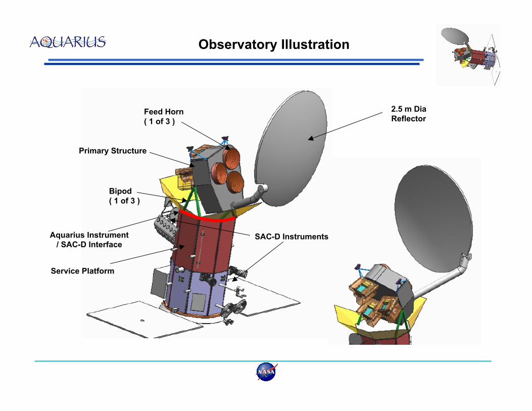
Observatory Illustration
2.5 m Dia
ReflectorFeed Horn
( 1 of 3 )
Primary Structure
Bipod
( 1 of 3 )
Service Platform
SAC-D InstrumentsAquarius Instrument
/ SAC-D Interface
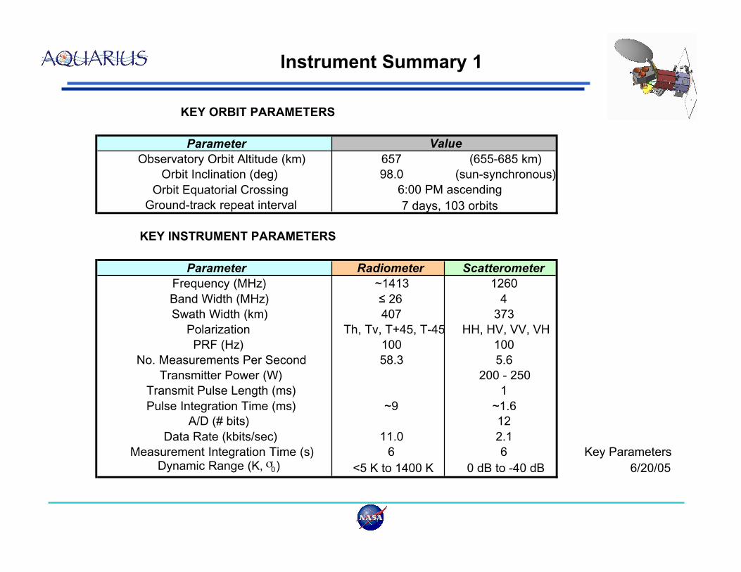
Instrument Summary 1
KEY ORBIT PARAMETERS
Parameter
Observatory Orbit Altitude (km) 657 (655-685 km)
Orbit Inclination (deg) 98.0 (sun-synchronous)
Orbit Equatorial Crossing
Ground-track repeat interval
KEY INSTRUMENT PARAMETERS
Parameter Radiometer Scatterometer
Frequency (MHz) ~1413 1260
Band Width (MHz) " 26 4
Swath Width (km) 407 373
Polarization Th, Tv, T+45, T-45 HH, HV, VV, VH
PRF (Hz) 100 100
No. Measurements Per Second 58.3 5.6
Transmitter Power (W) 200 - 250
Transmit Pulse Length (ms) 1
Pulse Integration Time (ms) ~9 ~1.6
A/D (# bits) 12
Data Rate (kbits/sec) 11.0 2.1
Measurement Integration Time (s) 6 6 Key ParametersDynamic Range (K, !0) <5 K to 1400 K 0 dB to -40 dB 6/20/05
Value
6:00 PM ascending
7 days, 103 orbits
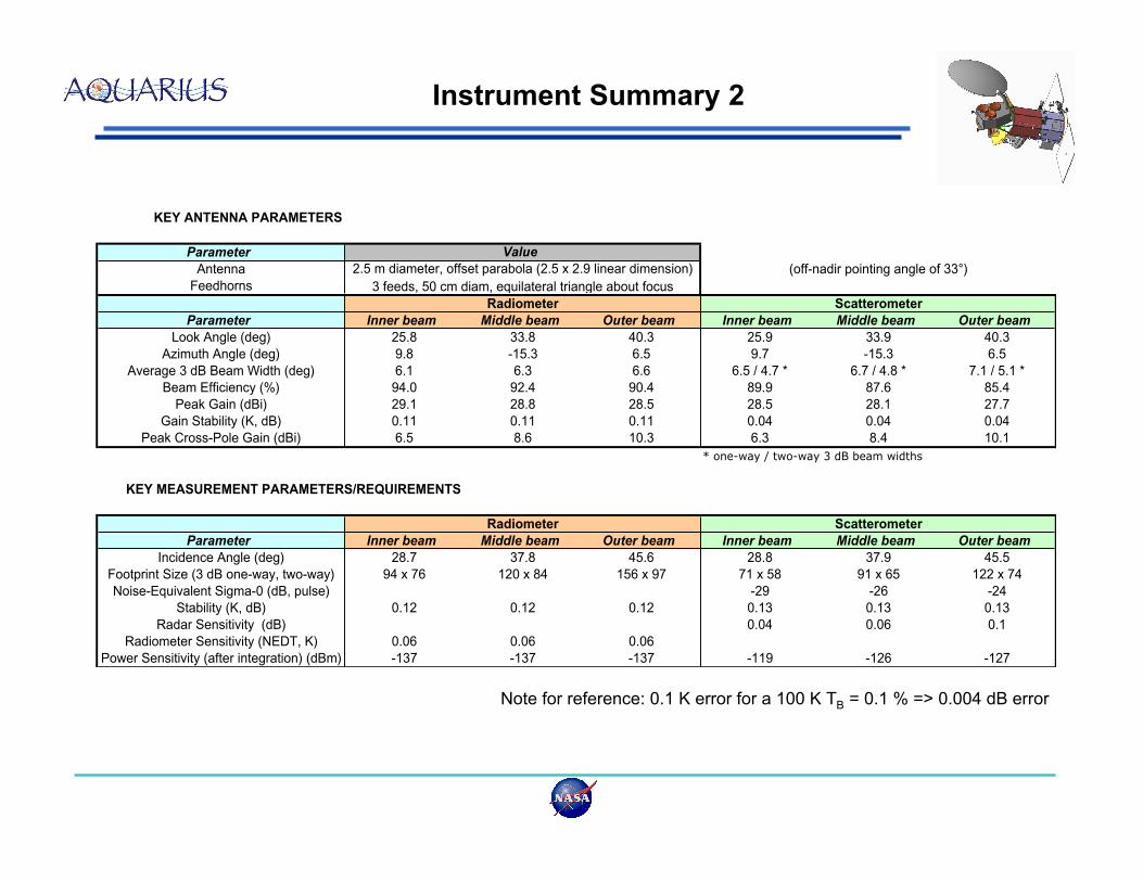
Instrument Summary 2
KEY ANTENNA PARAMETERS
Parameter
Antenna (off-nadir pointing angle of 33°)
Feedhorns
Radiometer Scatterometer
Parameter Inner beam Middle beam Outer beam Inner beam Middle beam Outer beam
Look Angle (deg) 25.8 33.8 40.3 25.9 33.9 40.3
Azimuth Angle (deg) 9.8 -15.3 6.5 9.7 -15.3 6.5
Average 3 dB Beam Width (deg) 6.1 6.3 6.6 6.5 / 4.7 * 6.7 / 4.8 * 7.1 / 5.1 *
Beam Efficiency (%) 94.0 92.4 90.4 89.9 87.6 85.4
Peak Gain (dBi) 29.1 28.8 28.5 28.5 28.1 27.7
Gain Stability (K, dB) 0.11 0.11 0.11 0.04 0.04 0.04
Peak Cross-Pole Gain (dBi) 6.5 8.6 10.3 6.3 8.4 10.1
* one-way / two-way 3 dB beam widths
KEY MEASUREMENT PARAMETERS/REQUIREMENTS
Radiometer Scatterometer
Parameter Inner beam Middle beam Outer beam Inner beam Middle beam Outer beam
Incidence Angle (deg) 28.7 37.8 45.6 28.8 37.9 45.5
Footprint Size (3 dB one-way, two-way) 94 x 76 120 x 84 156 x 97 71 x 58 91 x 65 122 x 74
Noise-Equivalent Sigma-0 (dB, pulse) -29 -26 -24
Stability (K, dB) 0.12 0.12 0.12 0.13 0.13 0.13
Radar Sensitivity (dB) 0.04 0.06 0.1
Radiometer Sensitivity (NEDT, K) 0.06 0.06 0.06
Power Sensitivity (after integration) (dBm) -137 -137 -137 -119 -126 -127
3 feeds, 50 cm diam, equilateral triangle about focus
Value
2.5 m diameter, offset parabola (2.5 x 2.9 linear dimension)
Note for reference: 0.1 K error for a 100 K TB = 0.1 % => 0.004 dB error
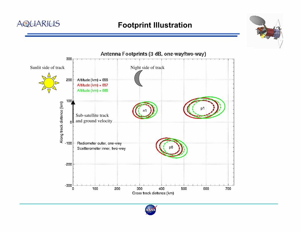
Footprint Illustration
Sub-satellite track
and ground velocity
Sunlit side of track Night side of track
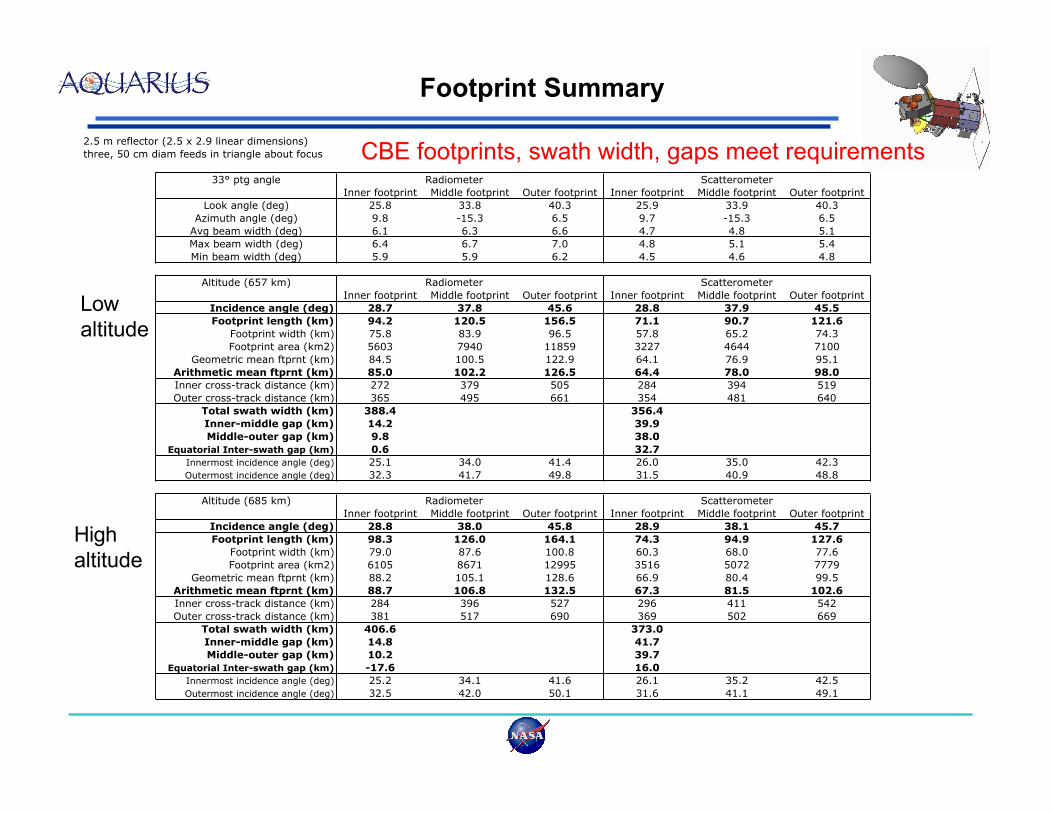
Footprint Summary
2.5 m reflector (2.5 x 2.9 linear dimensions)
three, 50 cm diam feeds in triangle about focus
33° ptg angle Radiometer Scatterometer
Inner footprint Middle footprint Outer footprint Inner footprint Middle footprint Outer footprint
Look angle (deg) 25.8 33.8 40.3 25.9 33.9 40.3
Azimuth angle (deg) 9.8 -15.3 6.5 9.7 -15.3 6.5
Avg beam width (deg) 6.1 6.3 6.6 4.7 4.8 5.1
Max beam width (deg) 6.4 6.7 7.0 4.8 5.1 5.4
Min beam width (deg) 5.9 5.9 6.2 4.5 4.6 4.8
Altitude (657 km) Radiometer Scatterometer
Inner footprint Middle footprint Outer footprint Inner footprint Middle footprint Outer footprint
Incidence angle (deg) 28.7 37.8 45.6 28.8 37.9 45.5
Footprint length (km) 94.2 120.5 156.5 71.1 90.7 121.6
Footprint width (km) 75.8 83.9 96.5 57.8 65.2 74.3
Footprint area (km2) 5603 7940 11859 3227 4644 7100
Geometric mean ftprnt (km) 84.5 100.5 122.9 64.1 76.9 95.1
Arithmetic mean ftprnt (km) 85.0 102.2 126.5 64.4 78.0 98.0
Inner cross-track distance (km) 272 379 505 284 394 519
Outer cross-track distance (km) 365 495 661 354 481 640
Total swath width (km) 388.4 356.4
Inner-middle gap (km) 14.2 39.9
Middle-outer gap (km) 9.8 38.0
Equatorial Inter-swath gap (km) 0.6 32.7
Innermost incidence angle (deg) 25.1 34.0 41.4 26.0 35.0 42.3
Outermost incidence angle (deg) 32.3 41.7 49.8 31.5 40.9 48.8
Altitude (685 km) Radiometer Scatterometer
Inner footprint Middle footprint Outer footprint Inner footprint Middle footprint Outer footprint
Incidence angle (deg) 28.8 38.0 45.8 28.9 38.1 45.7
Footprint length (km) 98.3 126.0 164.1 74.3 94.9 127.6
Footprint width (km) 79.0 87.6 100.8 60.3 68.0 77.6
Footprint area (km2) 6105 8671 12995 3516 5072 7779
Geometric mean ftprnt (km) 88.2 105.1 128.6 66.9 80.4 99.5
Arithmetic mean ftprnt (km) 88.7 106.8 132.5 67.3 81.5 102.6
Inner cross-track distance (km) 284 396 527 296 411 542
Outer cross-track distance (km) 381 517 690 369 502 669
Total swath width (km) 406.6 373.0
Inner-middle gap (km) 14.8 41.7
Middle-outer gap (km) 10.2 39.7
Equatorial Inter-swath gap (km) -17.6 16.0
Innermost incidence angle (deg) 25.2 34.1 41.6 26.1 35.2 42.5
Outermost incidence angle (deg) 32.5 42.0 50.1 31.6 41.1 49.1
CBE footprints, swath width, gaps meet requirements
Low
altitude
High
altitude
sec
Antenna AntennaAntenna
0.00 0.01 0.02 0.03 0.04 0.05 0.06 0.07 0.08 0.09 0.10 0.11 0.12
Antenna Antenna Antenna Antenna NDAcal calcalcal
Beam 1
Tx_H
Beam 1
Tx_V
Beam 1
Tx_V
Beam 1_V
Noise only
Beam 1
Tx H
Rcv_protect
One Aquarius Radiometer sub-cycle, 120 ms
Rx_V Rx_V Rx_HRx_H
Beam 1_H
Noise only
One Aquarius Scatterometer Timing Cycle, 180 ms
Beam 2
Tx_H
Beam 2
Tx_V
Beam 2
Tx_V
Beam 2_V
Noise only
Beam 2
Tx H
Rx_V Rx_V Rx_HRx_H
Beam 2_H
Noise only
sec0.12 0.13 0.14 0.15 0.16 0.17 0.18 0.19 0.20 0.21 0.22 0.23 0.24
Beam 3
Tx_H
Beam 3
Tx_V
Beam 3
Tx_V
Beam 3_V
Noise only
Beam 3
Tx H
Rx_V Rx_V Rx_HRx_H
Beam 3_H
Noise only
Beam 1
Tx_H
Beam 1
Tx_V
Beam 1
Tx_V
Beam1_V
Noise only
Beam 1
Tx H
Rx_V Rx_V Rx_HRx_H
Beam 1_H
Noise only
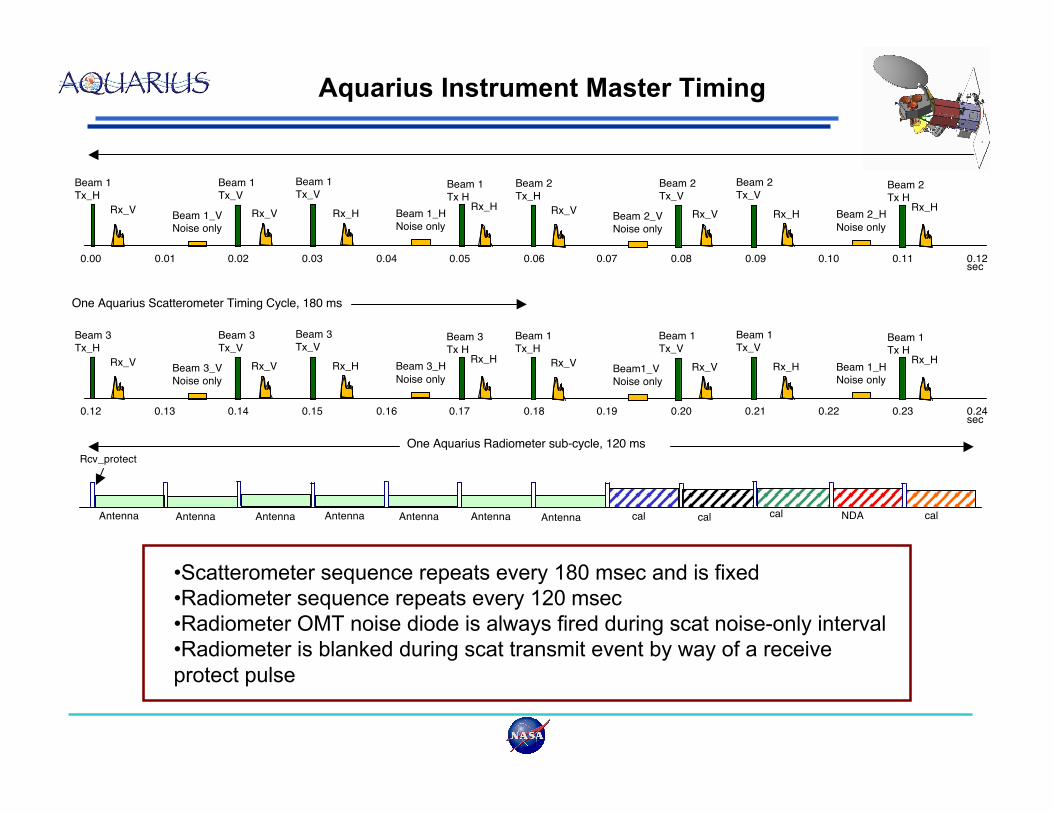
•Scatterometer sequence repeats every 180 msec and is fixed
•Radiometer sequence repeats every 120 msec
•Radiometer OMT noise diode is always fired during scat noise-only interval
•Radiometer is blanked during scat transmit event by way of a receive
protect pulse
Aquarius Instrument Master Timing
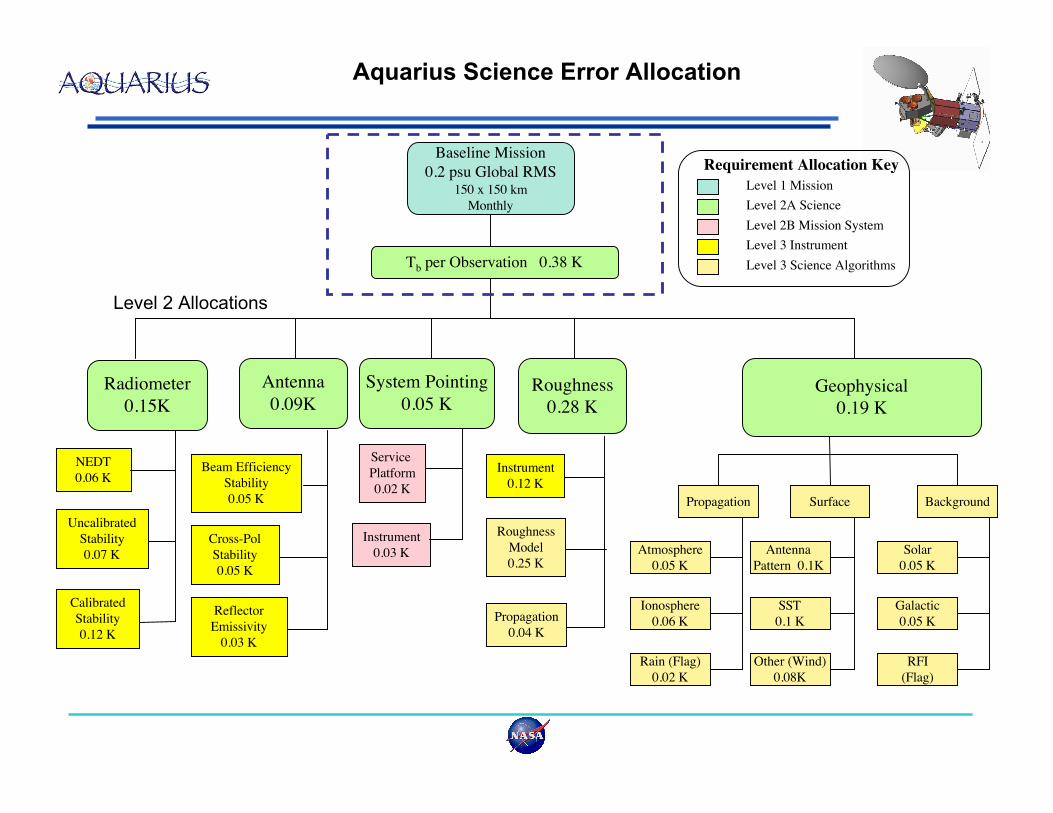
Aquarius Science Error Allocation
System Pointing
0.05 KRoughness
0.28 K
Radiometer
0.15KGeophysical
0.19 K
Level 1 Mission
Level 2A Science
Level 2B Mission System
Level 3 Instrument
Level 3 Science Algorithms
Requirement Allocation Key
Roughness
Model
0.25 K
Instrument
0.12 K
Propagation
0.04 K
NEDT
0.06 K
Uncalibrated
Stability
0.07 K
Service
Platform
0.02 K
Instrument
0.03 K
Level 2 Allocations
Antenna
0.09K
Beam Efficiency
Stability
0.05 K
Cross-Pol
Stability
0.05 K
Calibrated
Stability
0.12 K
Reflector
Emissivity
0.03 K
Atmosphere
0.05 K
RFI
(Flag)
SST
0.1 K
Antenna
Pattern 0.1K
Solar
0.05 K
Galactic
0.05 K
Ionosphere
0.06 K
Rain (Flag)
0.02 K
Propagation Surface Background
Other (Wind)
0.08K
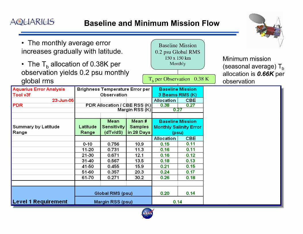
Baseline Mission
0.2 psu Global RMS150 x 150 km
Monthly
Tb per Observation 0.38 K
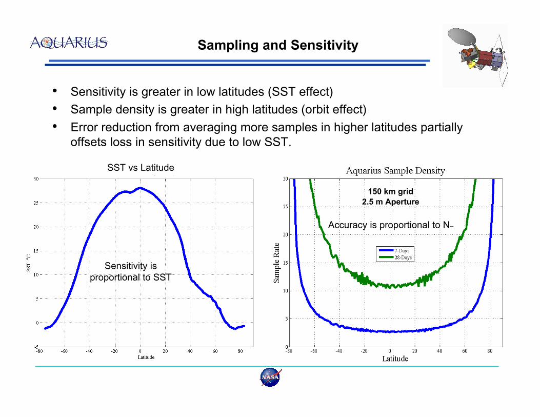
Sampling and Sensitivity
• Sensitivity is greater in low latitudes (SST effect)
• Sample density is greater in high latitudes (orbit effect)
• Error reduction from averaging more samples in higher latitudes partially
offsets loss in sensitivity due to low SST.
SST vs Latitude
Sensitivity is
proportional to SST
150 km grid
2.5 m Aperture
Accuracy is proportional to N_


![THE PARABOLOIDAL REFLECTOR ANTENNA IN RADIO …lib.iszf.irk.ru/The Paraboloidal Reflector Antenna... · chapter reference lists as [Gold, pp]. We omit a treatment of polarisation](https://img.pdfslide.net/doc/110x75/5f71221125ae015eed4f9967/the-paraboloidal-reflector-antenna-in-radio-libiszfirkruthe-paraboloidal-reflector.jpg)