Embed Size (px)
Citation preview

Self-calibrating, event-driven flow controland measurement
Heinz A. Preisig and Sebastian Roll
Department of Chemical EngineeringNorwegian University of Science and Technology (NTNU)
Trondheim, Norway
Abstract: This paper introduces a simple self-calibrating liquid flow rate control system. Alevel glass containing discrete optical level sensors is connected on the flow line upstream ofthe pump. The optical sensors in the level glass provide level-event information and definevolumes that can be used to calibrate and control the pump. The system is continuous and isobserved by a quantiser, making it overall a discrete-event dynamic system to be controlled bya corresponding controller.The set-up was installed as a reflux system on a set of distillation columns where the distillateis condensed below the top of the column, providing a industrial-like physical arrangement ofthe different components. The control system is low-cost and therefore provides a reasonablealternative for flow control and flow measurement.
1. INTRODUCTION
Flow control is a common process operation. It normallyinvolves a flow measurement which is used to controla pump of one or the other kind. The alternative is ametering pump, which is an accurate volume transportdevice. A metering pump requires a construction thatmakes the flow rate nearly independent of the pressuresbefore and after the pump. This makes it possible tocalibrate the pump accurately, thereby relating the controlinput to the pumping rate.
In this project we were seeking a cheap and simple alter-native for both components namely the measurement andthe controlled pump. The flow measurement should notonly be simple but also robust and the pump should havethe basic properties of a metering pump. The result was aself-calibrating liquid flow control system that uses a levelglass for observing the condition of having the outflow ofthe pump to match the inflow. The level glass also serves asthe volume standard used for the on-line auto-calibrationof the pump. We utilise the arrangement as a reflux pumpand reflux measurement system on distillation columns.
Fig. 1. Schematic of event-driven flow control
Fig. 2. Pipe with discrete optical liquid level sensors, usedfor flow control
2. PHYSICAL ARRANGEMENT
The physical arrangement consists of two main compo-nents: a level glass and a pump. The level glass is connectedto the flow line before the pump via a generously wideconnection so as to not delay the level change in the levelglass. The pump then is put into the flow line movingthe fluid. The level glass is equipped with six discrete leveldetectors, which provide an event-signal whenever the levelpasses an optical sensor. The dimension of the level glassand the location of the sensors provides a set of knownvolumes, which can be used for the calibration and controlof the pump. The physical dimension of the level glass arechosen to be in a reasonable relation to the expected rangeof flow rates in the line. Secondarily the geometry must besuch that the sensors can be mounted easily. In addition,a solenoid tab is put into the line before the level classconnection so as to interrupt the supply flow, enabling theon-line calibration of the pump.
Preprints of the 8th IFAC Symposium on Advanced Control of Chemical ProcessesThe International Federation of Automatic ControlFurama Riverfront, Singapore, July 10-13, 2012
© IFAC, 2012. All rights reserved. 650
The peristaltic pump provides the volume transport over areasonable range of inflow/outflow pressures of the pumpand generates a head that is suitable for our application,namely pumping the distillate that we condense on theside of the column, back to the top, thus providing thenecessary reflux. Volume transporters are usually movingsmall constant volumes generated in the pump by toothedwheels or other mechanisms. This makes the flow pulsat-ing, which has a negative effect on the accuracy of the flowrate estimates.
3. DISCRETE-EVENT DYNAMIC CONTROLLER
The overall system is a hybrid of a continuous system anda discrete-event observed system. With the measurementbeing event-based, the controller is event-based. The taskis to design a Discrete-Event Dynamic controller, a DEDcontroller. For the design of the DED controller, weuse the techniques discussed in Preisig [1996], Philips[2001], Philips et al. [2003]. The one-dimensional statespace, being the level in the level glass, is quantised. Thenumber and location of the discrete sensors determine thediscretisation of the state space, dividing it into sevendiscrete states. Five of those states corresponds to thevolume space between two sensors. In addition there arethe two additional volume spaces, one above the top sensorand one below the bottom sensor. The sensors report viaa process interface (digital input) an event of passing asensor to the computing device and thus to the controlalgorithm.
3.1 Time event
The DED controller is designed to keep the level withinthe middle domain. If the supply flow increases, the levelwill increase and eventually when the level reaches theupper boarder of the middle domain a state event will bereported. At this point the pump rate will be increased.The aim is to bring the process back to the intermediatedomain. If the increase of the pump rate was too small andit happens that the level settles somewhere in the currentupper domain, no level event will occur.
To get insight into the problem consider the differencebetween sampled systems and event-driven systems: In thesampled system, the signal value is read every samplingtime instance. So, sampling is driven by a clock. In thecase of an event-driven system, the ’reading’ is done inthe opposite direction, namely the value (state-boundary)is given and if the process passes it an event signal isdispatched. This makes the process being the ’clock’. Iffor one or the other reason, a state event is not directlyobservable, one may generate a virtual event by usinga prediction in which one replaces the process with astop watch. The state event is then replaced by a timeevent, which is the time when the unobservable event isexpected to occur. Thus one can view this mechanismas substituting an unobservable event with a stop-watchevent, de facto a time event.
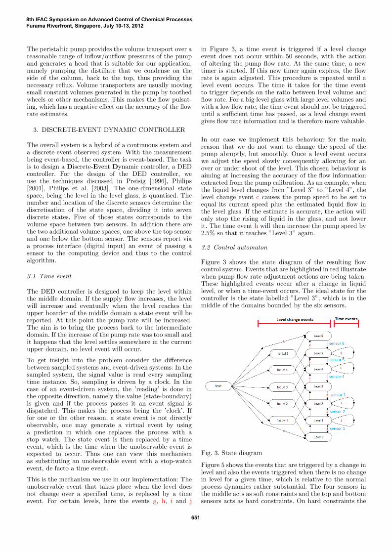
This is the mechanism we use in our implementation: Theunobservable event that takes place when the level doesnot change over a specified time, is replaced by a timeevent. For certain levels, here the events g, h, i and j
in Figure 3, a time event is triggered if a level changeevent does not occur within 50 seconds, with the actionof altering the pump flow rate. At the same time, a newtimer is started. If this new timer again expires, the flowrate is again adjusted. This procedure is repeated until alevel event occurs. The time it takes for the time eventto trigger depends on the ratio between level volume andflow rate. For a big level glass with large level volumes andwith a low flow rate, the time event should not be triggereduntil a sufficient time has passed, as a level change eventgives flow rate information and is therefore more valuable.
In our case we implement this behaviour for the mainreason that we do not want to change the speed of thepump abruptly, but smoothly. Once a level event occurswe adjust the speed slowly consequently allowing for anover or under shoot of the level. This chosen behaviour isaiming at increasing the accuracy of the flow informationextracted from the pump calibration. As an example, whenthe liquid level changes from ”Level 3” to ”Level 4”, thelevel change event c causes the pump speed to be set toequal its current speed plus the estimated liquid flow inthe level glass. If the estimate is accurate, the action willonly stop the rising of liquid in the glass, and not lowerit. The time event h will then increase the pump speed by2.5% so that it reaches ”Level 3” again.
3.2 Control automaton
Figure 3 shows the state diagram of the resulting flowcontrol system. Events that are highlighted in red illustratewhen pump flow rate adjustment actions are being taken.These highlighted events occur after a change in liquidlevel, or when a time-event occurs. The ideal state for thecontroller is the state labelled ”Level 3”, which is in themiddle of the domains bounded by the six sensors.
Fig. 3. State diagram
Figure 5 shows the events that are triggered by a change inlevel and also the events triggered when there is no changein level for a given time, which is relative to the normalprocess dynamics rather substantial. The four sensors inthe middle acts as soft constraints and the top and bottomsensors acts as hard constraints. On hard constraints the
8th IFAC Symposium on Advanced Control of Chemical ProcessesFurama Riverfront, Singapore, July 10-13, 2012
651

controller shifts to maximum action, which is full speed onthe top and zero on the bottom.
Fig. 4. Symbol definition for Figure 5.
Fig. 5. Time and level change events.1 PFR refers to pump flow rate
The level change events b, c, d and e trigger an actionthat sets V̇p (pump flow rate) equal or close to V̇in (flow
rate coming in). In order for this to happen, V̇in must bedeterminable. If the level rises from ”Level 3” to ”Level 4”,it must before that have risen from ”Level 2” to ”Level3” in order for V̇in to be known. As an example of theopposite, if the level were to oscillate between ”Level 3”and ”Level 4”, the level change event c will not be triggeredat the change from ”Level 3” to ”Level 4”.
4. PUMP CALIBRATION
The solenoid valve introduced into the line enables theisolation of the level glass and the pump from the supply.Since the volumes in the level glass are known, one can usethe fluid in the level glass for the calibration of the pump.The procedure is controlled by a calibration automaton.It implements a sequence of operations:
a: open valve g: compute flow ratesb: close valve h: change pump speed parameterc: start pump i: increase counter by 1d: stop pump j: start timee: start control mode k: note timef: start x seconds countdown
Table 1. Calibration actions
Calibration procedures (i), (ii) and (iii) are done in suc-cession, one time after assembly of the system is finished:
(i) Find correlation between one pump input andflow rate. This is done by specifying an input signal to thepump and collecting the output flow into a container witha known volume. The flow rate, V̇ , for the given input,u, is found by measuring the time, ∆t required to fill thevolume-calibrated container to volume V :
V̇ (u) =V
∆t(u)(1)
Fig. 6. (ii): Automaton state-flow diagram for level volumeidentification
(ii) Find volume between sensors using flow rate fromthe previous volume calibration (i). As one flow rate isknown, this is used to calculate the relevant volumes.Figure 6 shows the state-flow diagram for the calibrationautomaton: The level glass is filled to and beyond the topsensor by opening the valve and stopping the pump. Whenthe liquid level is sufficiently above the top sensor (which isdetermined by a timer of a few seconds), the valve closesand the pump is started at a given rpm correspondingto input used in (i), thus starting the emptying of thelevel glass. When the liquid level passes through the topsensor, i.e. enters ”Level 5”, a timer starts. For each newlevel entered, the time is noted. When the liquid levelreaches ”Level 0”, the pump is stopped and the valveopens, allowing the liquid to fill the level glass again. Thisexperiment is repeated a given number of times in order toalso get statistical information. Once the last experimentis completed, the automaton algorithm switches back tocontrol mode.
The volume of ”Level n” is calculated as:
V (n) = V̇ (u) ∗ (tn(u) − tn−1(u)) (2)
The results are used by the control algorithm. The lastcalibration procedure uses the volume from top sensor tobottom sensor,
∑v(i).
(iii) Find correlation between pump inputs andflow rates for entire input span, using the equation:
V̇ (u) =V
t5(u) − t0(u)(3)
t5(u) − t0(u) is the time it takes to the level to dropfrom ”Level 5” to ”Level 0”, corresponding to the volumebetween the top and bottom level sensor. This is the sameequation as the first calibration procedure, but since thevolume of the level glass is now known, is can be usedas fixed volume container. The procedure is shown inFigure 7. The level glass is filled and emptied, similar tothe procedure explained in (ii), but the algorithm cyclesthrough an array of specified pump speeds instead ofusing the same speed for all the calibration cycles. Italso does not note the time when the liquid level entersthe intermediate levels, but the time is taken only whenentering ”Level 5” and ”Level 0”.
8th IFAC Symposium on Advanced Control of Chemical ProcessesFurama Riverfront, Singapore, July 10-13, 2012
652
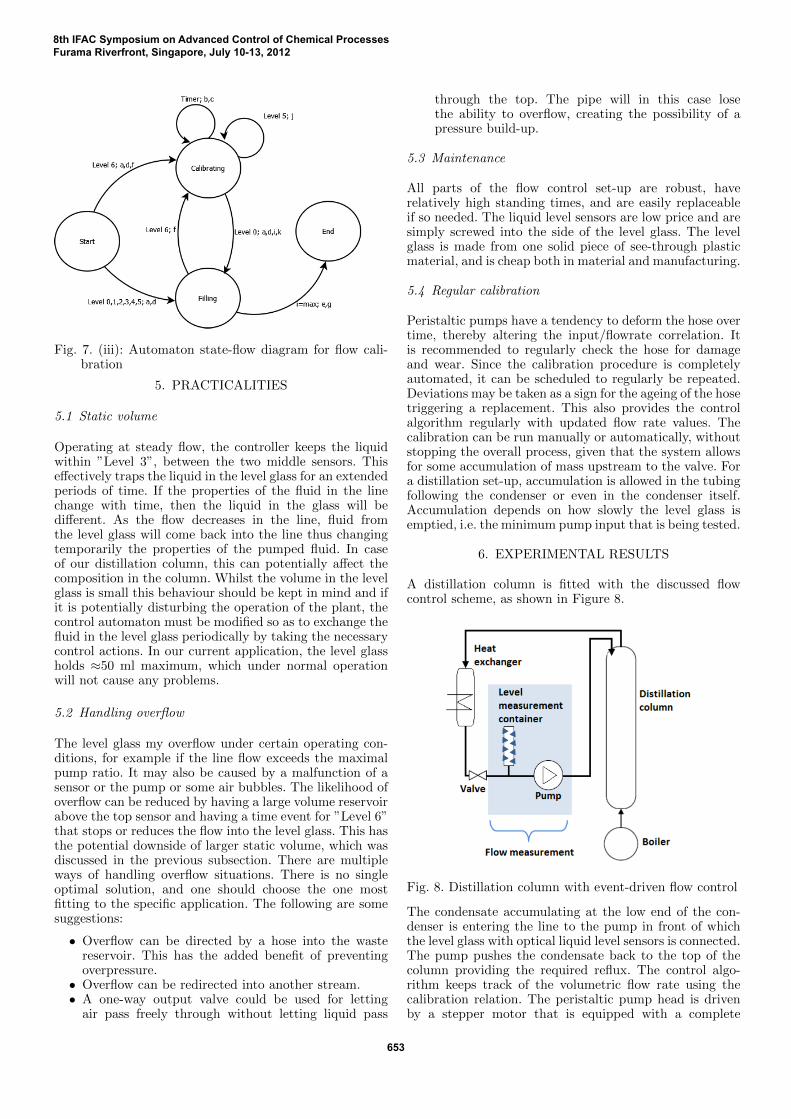
Fig. 7. (iii): Automaton state-flow diagram for flow cali-bration
5. PRACTICALITIES
5.1 Static volume
Operating at steady flow, the controller keeps the liquidwithin ”Level 3”, between the two middle sensors. Thiseffectively traps the liquid in the level glass for an extendedperiods of time. If the properties of the fluid in the linechange with time, then the liquid in the glass will bedifferent. As the flow decreases in the line, fluid fromthe level glass will come back into the line thus changingtemporarily the properties of the pumped fluid. In caseof our distillation column, this can potentially affect thecomposition in the column. Whilst the volume in the levelglass is small this behaviour should be kept in mind and ifit is potentially disturbing the operation of the plant, thecontrol automaton must be modified so as to exchange thefluid in the level glass periodically by taking the necessarycontrol actions. In our current application, the level glassholds ≈50 ml maximum, which under normal operationwill not cause any problems.
5.2 Handling overflow
The level glass my overflow under certain operating con-ditions, for example if the line flow exceeds the maximalpump ratio. It may also be caused by a malfunction of asensor or the pump or some air bubbles. The likelihood ofoverflow can be reduced by having a large volume reservoirabove the top sensor and having a time event for ”Level 6”that stops or reduces the flow into the level glass. This hasthe potential downside of larger static volume, which wasdiscussed in the previous subsection. There are multipleways of handling overflow situations. There is no singleoptimal solution, and one should choose the one mostfitting to the specific application. The following are somesuggestions:
• Overflow can be directed by a hose into the wastereservoir. This has the added benefit of preventingoverpressure.
• Overflow can be redirected into another stream.• A one-way output valve could be used for letting
air pass freely through without letting liquid pass
through the top. The pipe will in this case losethe ability to overflow, creating the possibility of apressure build-up.
5.3 Maintenance
All parts of the flow control set-up are robust, haverelatively high standing times, and are easily replaceableif so needed. The liquid level sensors are low price and aresimply screwed into the side of the level glass. The levelglass is made from one solid piece of see-through plasticmaterial, and is cheap both in material and manufacturing.
5.4 Regular calibration
Peristaltic pumps have a tendency to deform the hose overtime, thereby altering the input/flowrate correlation. Itis recommended to regularly check the hose for damageand wear. Since the calibration procedure is completelyautomated, it can be scheduled to regularly be repeated.Deviations may be taken as a sign for the ageing of the hosetriggering a replacement. This also provides the controlalgorithm regularly with updated flow rate values. Thecalibration can be run manually or automatically, withoutstopping the overall process, given that the system allowsfor some accumulation of mass upstream to the valve. Fora distillation set-up, accumulation is allowed in the tubingfollowing the condenser or even in the condenser itself.Accumulation depends on how slowly the level glass isemptied, i.e. the minimum pump input that is being tested.
6. EXPERIMENTAL RESULTS
A distillation column is fitted with the discussed flowcontrol scheme, as shown in Figure 8.
Fig. 8. Distillation column with event-driven flow control
The condensate accumulating at the low end of the con-denser is entering the line to the pump in front of whichthe level glass with optical liquid level sensors is connected.The pump pushes the condensate back to the top of thecolumn providing the required reflux. The control algo-rithm keeps track of the volumetric flow rate using thecalibration relation. The peristaltic pump head is drivenby a stepper motor that is equipped with a complete
8th IFAC Symposium on Advanced Control of Chemical ProcessesFurama Riverfront, Singapore, July 10-13, 2012
653

process interface that connects directly to the RS 485instrumentation bus. The level glass is approx 15 cm highand holds ≈ 50 ml between the top and bottom sensor.
A calibration program is realised as a separate program,making it possible to run the calibration independentof the control program. The program is also used todetermine volumes between the sensors in the level glass.
6.1 Calibration results
Figure 9 shows the correlation between pump rpm, beingthe input to the pump, and the volumetric flow rate. Thegraph is linear up to ≈ 90 rpm at which point linearityis lost. We found that this phenomena is reproducible.The detailed cause is not known, but it can likely beattributed to some interaction between deformation of thehose and the workings of the peristaltic pump. Under nor-mal operations, the pump does not exceed 90 rpm. Onlyunder extreme conditions and when the system enters themaximum level domain, the pump is operating at highspeed up to a maximum 150 rpm.
Fig. 9. line: Results from calibration procedure 3. Red line:linear regression.
The use of a linear correlation is easy and convenient,but can be inaccurate when getting into the non-linearregion. If so necessary one may consider fitting a higher-order polynomial that is capable of capturing the irregu-larity feature reasonably accurate. Alternatively one mayconsider fitting piecewise either with linear or non-linearfunctions.
6.2 Dynamic results
A limited number of dynamic experiments were done,mainly to inspect if changes in the speed of rotation hasa significant effect on the estimated flow rate compared tothe actual flow rate. The experiments were done using anintegral volume measurement on the outflow changing theconditions. The speed of rotation was changed repeatedlyusing different patterns. This provided some insight intothe dependency on the dynamics, which was found surpris-ingly minimal. More precise information would require aprecise dynamic volume or mass flow measurement, whichwas not available at the time.
Dynamic control experiments showed excellent resultsboth off-line as well as implemented on the distillation.
Certainly, a combination of flow measurement and PIDcontroller could be tuned to have a smaller settling time,for example, but at the costs of larger variations and, notat least, having to implement a flow measurement Thehere-installed controller is acting in the time-frame dic-tated by the volume in the measurement device. Adjustingthe volume changes the dynamic behaviour, besides thetwo main parameters in the DEDS controller, which is thetime to change the flow rate and the rate with which it ischanged.
CONCLUSION
The event-based, discretised-state flow control system con-sists of a volume transporter, a cylindrical vertical glasswith six discrete liquid level sensors, and a computerinterface. The difference between inflow and outflow isestimated from the time taken for a change to occur in theliquid height in the level glass detected by the discrete levelsensors. The control algorithm adjusts the pump speed andthus the pumping ratio accordingly. The fully automatedcalibration procedure interferes minimally with the opera-tion of the assembly and can thus be periodically repeated,thereby maintaining a high accuracy of the estimated flowrate through regular re-calibration.
The self-calibrating flow rate control structure is low-cost, robust and easily implemented and maintained. Therealisation of the automaton algorithm is extremely simpleand consists of a recursive two-table look-up procedure.The first table provides the next state given the currentstate and current event whilst the second gives the set ofactions given the current state and the current event. Itthus requires only memory for the automata tables and thefew lines of code. The assembly can be used to manuallyor automatically calibrate both on and off-line. Its usehas been demonstrated on a set of lab-scale distillationcolumns, where it acts as reflux measurement and pumpsystem.
In addition, if one does not require flow information, themetering pump can be replaced by a generic cheap pumpand calibration can be abandoned.
REFERENCES
P P H H Philips. Modelling, Control and Fault Detection ofDiscretely-Observed Systems. PhD thesis, TU Eindhoven, Eind-hoven, The Netherlands, 2001.
P P H H Philips, W P M H Heemels, H A Preisig, and P P JBosch van den. Control of quantised systems based on discrete-event models. International Journal of Control, 76(3):277–294,2003.
H A Preisig. A mathematical approach to discrete- event dynamicmodelling of hybrid systems. Computers & Chemical Engineering,20:S1301– S1306, 1996.
8th IFAC Symposium on Advanced Control of Chemical ProcessesFurama Riverfront, Singapore, July 10-13, 2012
654