Embed Size (px)
Citation preview
Proceedings of the International Symposium of Mechanism and Machine Science, 2017
AzC IFToMM – Azerbaijan Technical University
11-14 September 2017, Baku, Azerbaijan
98
Self-Calibrating Smart Mirror Design Kaya MANOĞLU1*, Barış TANER1, Onursal ÖNEN1, Serhan OZDEMİR1
1*Izmir Institute of Technology
IzTech Robotics Laboratory, Gülbahçe Mah., Urla, İzmir, Turkey
E-mail: [email protected]
Abstract
Self-Calibrating Smart Mirror is a source tracking mirror
that is designed in Izmir Instıtute of Technology. This
device uses ARM Cortex M4 chip to calibrate itself using
the sound in environment and execute tracking operations
to direct the mirror to the user. In this paper, mathematical
model, calibration, experiments for sensor capabilities and
tracking operations are presented and the prototype is
expressed.
Keywords: Robotics, human-machine interface, sound
tracking, source localization.
1. Introduction
Smart devices became common with the development
of processors and sensors which are used in devices
surrounding us and make them smarter every day with the
need of easier interaction of human and machine. Smarter
machines are designed to have the same communication
methods of human that are visual, tactile, kinesthetic and
auditory sensors [1] to be more sociable in the use of a
human.
These communication methods can be used for
increasing human perception in the slave environment that
is interfaced by a haptic device [2] or to increase level of
perception of the human commands by the machine [3].
As pointed in a research [4], some arcade games are using
visual, infra-red, inertial measurement units and ultrasonic
sensors to locate the users for shaping game inputs.
Tactile and kinesthetic information in action and sports
games as a reaction to the user by haptic devices are
widely used application examples of communication
between human and machine.
Other than sensing the motion of the human user by
haptic devices, the motion inputs of the user can be
detected by other means such as visual sensors using
cameras [5], IR sensors [6] and auditory sensors [7].
Visual and IR sensors are commonly used sensor types for
tracking environmental changes. These sensors are
powerful considering the achievable resolution of the
tracked workspace with respect to the auditory sensors;
However, they are limited with the field of view and
cannot locate outside of this region [1]. The field of view
depends on parameters such as focal length of the lens,
image sensor dimensions and distance to the measured
plane [8]. In some vision applications, field of view can be
enlarged using stereo vision techniques which include
rectification of multiple images and matching them to
create a larger field of view but this method requires
multiple cameras and greater computational costs [9].
One other way to locate user is using acoustic sensors.
This method is used in real world by creatures to locate
the sound source and give them a 360º field of view. It
also allows them to locate sources that are obscured by
any object that are not in the field of vision [1].
Researchers are using this method of localization in robots
for tracking, socializing and navigating which has various
application techniques.
In this paper, design of a smart mirror is described
with its sensors, processor and mathematical model,
which includes self-calibration, signal processing and
source tracking in two-dimensional plane. The mirror is
designed to be one Degree of Freedom (DoF) and uses an
ARM Cortex M4 chip, which can locate the sound source
using an array of microphones placed on the body.
2. Hardware used in Design
Device is composed of several electronics including
processor, sensors and actuators. In this project an ARM
based processor was selected and this chip was
STM32F407VGT6. In the market, this chip is used by
many third-party companies to build their own
prototyping boards in which one of them is the
STM32F4DISCOVERY Discovery board. This board
allows users to easily develop applications with
the STM32F407 high performance microcontrollers with
ARM® Cortex®-M4 32-bit core. It includes an ST-
LINK/V2 or ST-LINK/V2-A embedded debug tool, two
ST MEM’s digital accelerometers, a digital microphone,
one audio DAC with integrated class D speaker driver,
LEDs and push buttons and an USB OTG micro-AB
connector [10].
A basic sound sensor card is used in this robotic
application, which gives an analog output according to the
sound level of the environment. The specifications of this
sensor breakout are listed in Table 1.
Table 1. Sound sensor specifications
F1requency range 100 ~ 10,000 Hz
Sensitivity - 46 ± 2.0, (0 dB = 1V/Pa
) at 1K Hz
Power supply 5V maximum
Minimum Sensitivity to
Noise Ratio
58dB for digital output
A light weight servo motor that can rotate
approximately 180 degrees is placed beneath the mirror to
rotate it around the azimuth axis. Body of the device is
Proceedings of the International Symposium of Mechanism and Machine Science, 2017
AzC IFToMM – Azerbaijan Technical University
11-14 September 2017, Baku, Azerbaijan
99
made out of a foam-board for minimizing the
reverberation problems.
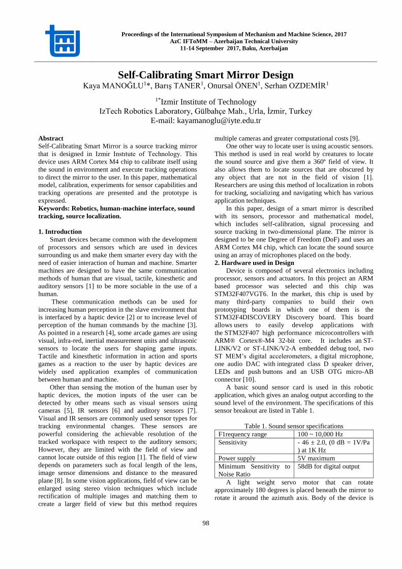
2. Deciding the Geometry
Sensor placement plays an important role in product
design and cabling since the way sensors are placed
changes both signal transfer and acquisition problems
with the sound tracking performance of the mirror. To
declare it clearly, sound acquisition performance of
microphones is affected by direction of the microphones.
This fact about the sensors is an outcome of the
experiment executed in this work. The experiment aims to
measure sound level using four identical sound sensors in
two different formations. One of the formations was
placing them as a linear array and the other one was
placing them radially as provided in Figure 1.
Fig.1. Test Formation for formation
The sensors in linear array set gives greater voltage
values for the sounds sourced directly in front, however,
other sensors in the same array set gives approximately
close voltage levels that cannot be distinguished easily.
The sensors in radial array set gives higher voltages once
the sound sourced from the normal angle like the previous
array set, however, it is easier to transfer signals from the
sensors to the microchip due to the tight packing of the
sensors.
In order to decide the geometry of the device, an
experiment is designed and executed, especially for
defining the microphone sensitivities at varying facing
angles and distances. In this experiment, source is placed
at different azimuth angles with varying distances from
the sensor and sound level is measured. The azimuth angle
and distances are given in Table 2.
Table 2 The Trial Table
Angle (degrees) Distance (cm)
0 10, 20, 40, 60, 80
30 10, 20, 40, 60, 80
45 10, 20, 40, 60, 80
60 10, 20, 40, 60, 80
90 10, 20, 40, 60, 80
Sound source is measured for an average duration of
6-7 seconds for every combination of Table 2. Sine wave
of 500 Hz is used as a sound source. As additional
information, it is known that the human sound is in a
range of 85 to 1050 Hz, lowest frequency as a male bass
sound and the highest as a female soprano. The results
showed that the distance of the source has a significant
effect in the sound level, as much as the microphone
angle.
Measurements were mapped according to the distance
and angle of the sound source with respect to the
microphone. Five distinct measurements are executed for
the angles of 0º, 30º, 45º, 60º and 90º, which include
measurements of varying distances provided in Table 1. 0º
is directly in front of the microphone and 90º is the
perpendicular angle to the direct line of sight of the
microphone. Tests are applied for every microphone and
the measurements are illustrated only for one microphone.
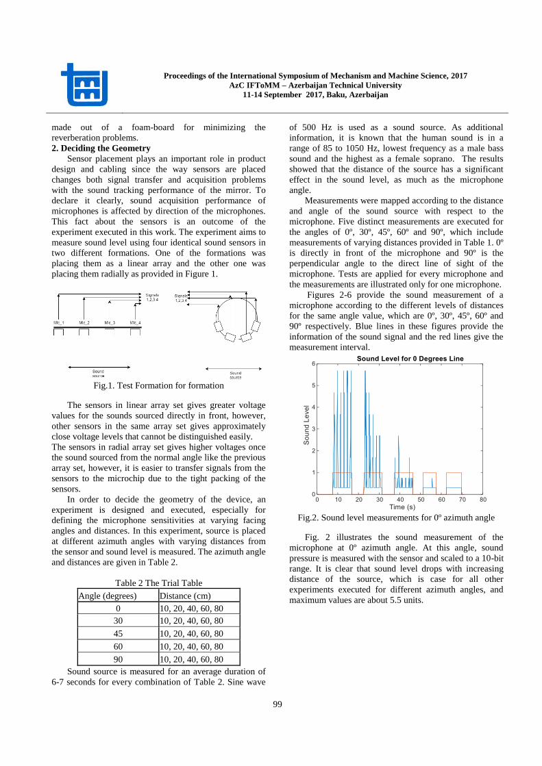
Figures 2-6 provide the sound measurement of a
microphone according to the different levels of distances
for the same angle value, which are 0º, 30º, 45º, 60º and
90º respectively. Blue lines in these figures provide the
information of the sound signal and the red lines give the
measurement interval.
Fig.2. Sound level measurements for 0º azimuth angle
Fig. 2 illustrates the sound measurement of the
microphone at 0º azimuth angle. At this angle, sound
pressure is measured with the sensor and scaled to a 10-bit
range. It is clear that sound level drops with increasing
distance of the source, which is case for all other
experiments executed for different azimuth angles, and
maximum values are about 5.5 units.
Proceedings of the International Symposium of Mechanism and Machine Science, 2017
AzC IFToMM – Azerbaijan Technical University
11-14 September 2017, Baku, Azerbaijan
100
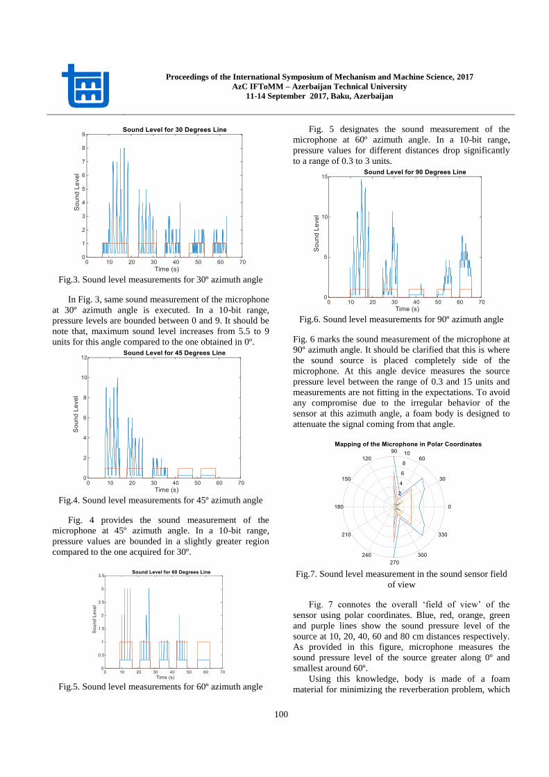
Fig.3. Sound level measurements for 30º azimuth angle
In Fig. 3, same sound measurement of the microphone
at 30º azimuth angle is executed. In a 10-bit range,
pressure levels are bounded between 0 and 9. It should be
note that, maximum sound level increases from 5.5 to 9
units for this angle compared to the one obtained in 0º.
Fig.4. Sound level measurements for 45º azimuth angle
Fig. 4 provides the sound measurement of the
microphone at 45º azimuth angle. In a 10-bit range,
pressure values are bounded in a slightly greater region
compared to the one acquired for 30º.
Fig.5. Sound level measurements for 60º azimuth angle
Fig. 5 designates the sound measurement of the
microphone at 60º azimuth angle. In a 10-bit range,
pressure values for different distances drop significantly
to a range of 0.3 to 3 units.
Fig.6. Sound level measurements for 90º azimuth angle
Fig. 6 marks the sound measurement of the microphone at
90º azimuth angle. It should be clarified that this is where
the sound source is placed completely side of the
microphone. At this angle device measures the source
pressure level between the range of 0.3 and 15 units and
measurements are not fitting in the expectations. To avoid
any compromise due to the irregular behavior of the
sensor at this azimuth angle, a foam body is designed to
attenuate the signal coming from that angle.
Fig.7. Sound level measurement in the sound sensor field
of view
Fig. 7 connotes the overall ‘field of view’ of the
sensor using polar coordinates. Blue, red, orange, green
and purple lines show the sound pressure level of the
source at 10, 20, 40, 60 and 80 cm distances respectively.
As provided in this figure, microphone measures the
sound pressure level of the source greater along 0º and
smallest around 60º.
Using this knowledge, body is made of a foam
material for minimizing the reverberation problem, which
Proceedings of the International Symposium of Mechanism and Machine Science, 2017
AzC IFToMM – Azerbaijan Technical University
11-14 September 2017, Baku, Azerbaijan
101
is shaped as a half circle with openings in four different
locations on the arc. These openings are specially
designed for not allowing the microphones getting signals
from the sides Foam type materials are especially used for
high frequency sound absorption above 2000 Hz, and it is
possible to obtain better results by more proper material
usage in the body. It is important to remark that this study
is just a concept and in the process of development at the
moment.
3. Localization Algorithm and Its Application
As expected, depending on the source location,
different sound levels will be obtained by each
microphone. Facing direction of each microphone is
defined as a vector, which in the end will give the
resultant vectors. It is said to be the logic of the system is
based on the estimation of that resultant vector Fig. 8.
Fig.8. Sound levels from different source distances with
varying microphone angles
A simple algorithm is developed for the system which
is shown in Fig. 9.
Fig.9. Diagram of the process
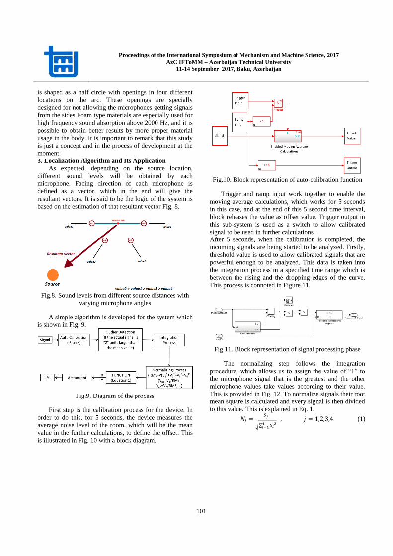
First step is the calibration process for the device. In
order to do this, for 5 seconds, the device measures the
average noise level of the room, which will be the mean
value in the further calculations, to define the offset. This
is illustrated in Fig. 10 with a block diagram.
Fig.10. Block representation of auto-calibration function
Trigger and ramp input work together to enable the
moving average calculations, which works for 5 seconds
in this case, and at the end of this 5 second time interval,
block releases the value as offset value. Trigger output in
this sub-system is used as a switch to allow calibrated
signal to be used in further calculations.
After 5 seconds, when the calibration is completed, the
incoming signals are being started to be analyzed. Firstly,
threshold value is used to allow calibrated signals that are
powerful enough to be analyzed. This data is taken into
the integration process in a specified time range which is
between the rising and the dropping edges of the curve.
This process is connoted in Figure 11.
Fig.11. Block representation of signal processing phase
The normalizing step follows the integration
procedure, which allows us to assign the value of “1” to
the microphone signal that is the greatest and the other
microphone values take values according to their value.
This is provided in Fig. 12. To normalize signals their root
mean square is calculated and every signal is then divided
to this value. This is explained in Eq. 1.
𝑁𝑗 =𝑆𝑗
√∑ 𝑆𝑖24
𝑖=1
, 𝑗 = 1,2,3,4 (1)
Proceedings of the International Symposium of Mechanism and Machine Science, 2017
AzC IFToMM – Azerbaijan Technical University
11-14 September 2017, Baku, Azerbaijan
102
Fig.12. Block representation of normalization process
After this step, we are applying a function to the
obtained microphone values to determine the direction of
the sound source by distinguishing the x and y
components of the required resultant normal vector using
Eq 2. When x and y components are obtained, it becomes
very simple to convert this to an angle of θ, by using the
arctangent function.
[𝑋𝑆𝑆𝑌𝑆𝑆] = [
∑ (𝑀𝑖𝑐𝑟𝑜𝑝ℎ𝑜𝑛𝑒 𝑉𝑎𝑙𝑢𝑒)𝑖 ∗ 𝑐𝑜𝑠𝜃𝑖4𝑖=1
∑ (𝑀𝑖𝑐𝑟𝑜𝑝ℎ𝑜𝑛𝑒 𝑉𝑎𝑙𝑢𝑒)𝑖 ∗ 𝑠𝑖𝑛𝜃𝑖4𝑖=1
] (2)
The code generation is executed using the Waijung
module in Matlab Simulink. This module is third-party
software that includes blocks for different operations such
as mathematical operations, logic operations and etc.
Using this software created model is downloaded in
discovery board.
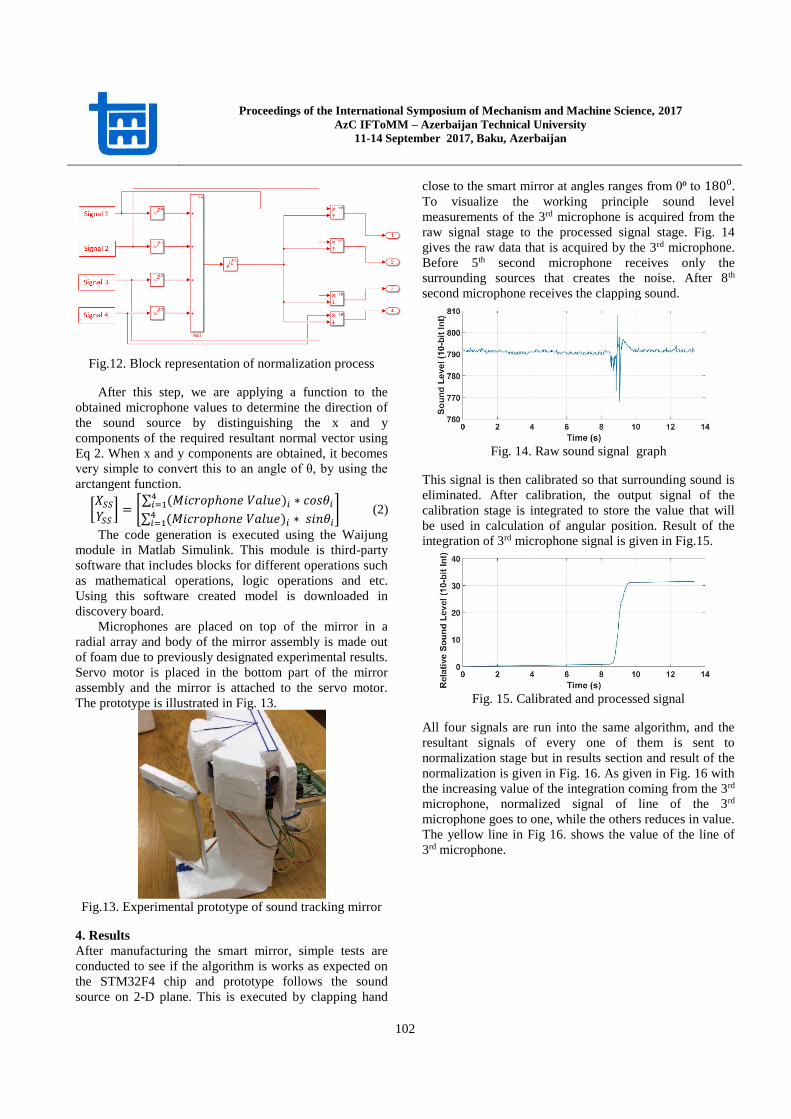
Microphones are placed on top of the mirror in a
radial array and body of the mirror assembly is made out
of foam due to previously designated experimental results.
Servo motor is placed in the bottom part of the mirror
assembly and the mirror is attached to the servo motor.
The prototype is illustrated in Fig. 13.
Fig.13. Experimental prototype of sound tracking mirror
4. Results
After manufacturing the smart mirror, simple tests are
conducted to see if the algorithm is works as expected on
the STM32F4 chip and prototype follows the sound
source on 2-D plane. This is executed by clapping hand
close to the smart mirror at angles ranges from 0⁰ to 180⁰. To visualize the working principle sound level
measurements of the 3rd microphone is acquired from the
raw signal stage to the processed signal stage. Fig. 14
gives the raw data that is acquired by the 3rd microphone.
Before 5th second microphone receives only the
surrounding sources that creates the noise. After 8th
second microphone receives the clapping sound.
Fig. 14. Raw sound signal graph
This signal is then calibrated so that surrounding sound is
eliminated. After calibration, the output signal of the
calibration stage is integrated to store the value that will
be used in calculation of angular position. Result of the
integration of 3rd microphone signal is given in Fig.15.
Fig. 15. Calibrated and processed signal
All four signals are run into the same algorithm, and the
resultant signals of every one of them is sent to
normalization stage but in results section and result of the
normalization is given in Fig. 16. As given in Fig. 16 with
the increasing value of the integration coming from the 3rd
microphone, normalized signal of line of the 3rd
microphone goes to one, while the others reduces in value.
The yellow line in Fig 16. shows the value of the line of
3rd microphone.

Proceedings of the International Symposium of Mechanism and Machine Science, 2017
AzC IFToMM – Azerbaijan Technical University
11-14 September 2017, Baku, Azerbaijan
103
Fig. 16. Signals after normalization
After the normalization process, x and y components of
the sound source vector is used to calculate the angular
position of the sound source with respect to the mirror
origin in 2-D plane. This is provided is Fig. 17.
Fig. 17. Angle calculation graph
As given in Fig. 17 a series of clap that is close to the 3rd
microphone, which is placed at 120⁰, results in a
calculated angle of 124⁰, with an error of 4⁰.
5. Comments and Conclusion
In this paper, a 1 DoF smart mirror is designed using 4
radially placed sound sensors. The purpose of this mirror
is to construct a system, which can be used in robotic
systems that interacts with humans. The controller of the
system is designed over the STM32F4 Discovery board
and the system is deployed on the chip using Matlab.
In preliminary design, microphone field of view is
revealed to be used in design of the mirror and sensors are
placed using this information. Field of view experiments
show that there is an unexpected rise in the sound level at
90º angle, where sound level is measured to be the largest.
To eliminate this problem sensors are placed in a foam
head that reduces the sound level coming from this angle.
After this stage, control algorithm is deployed in the
discovery board.
In this prototype, an integration is executed for every
signal and the resultant signals are normalized. This is
used to store the positional data, however, after several
repetitions of localization, integrated values that are feed
in the normalization get high values. This creates a
problem of latency once another sound source transmits
sound. In this particular case, device turns to the new
source slowly, since integration of the acquired sound
signal takes time to reach the previously integrated value.
To overcome that problem, smart mirror has to be reset,
which is done by a digital input given by the user.
Even though this system is designed as a smart mirror to
interact with humans, it may very well be equipped with
other device or objects along with a different line of
sensors, oriented towards commercial or industrial
purposes.
It should be mentioned that the curvilinear deployment of
sound sensors may also be regarded as a distributed sensor
network, whose detailed analysis is left for a later
research. But it is seen that as the number of sensors is
increased, localization resolution is also on the rise.
References
[1]. Murray, John C., Harry Erwin, and Stefan Wermter.
"Robotics sound-source localization and tracking
using interaural time difference and cross-
correlation." AI Workshop on NeuroBotics. 2004.
[2]. Taner, B., and M. İ. C. Dede. "Image Processing
Based Stiffness Mapping of a Haptic Device." New
Advances in Mechanisms, Mechanical Transmissions
and Robotics. Springer International Publishing,
pages 447-454, 2017.
[3]. Web,http://web.media.mit.edu/~cynthiab/Papers/Brea
zeal-TICS02.pdf
[4]. Breazeal, Cynthia, et al. "Learning from and about
others: Towards using imitation to bootstrap the
social understanding of others by robots." Artificial
life 11.1-2, pages 31-62, 2005.
[5]. Wermter, Stefan, et al. "Towards multimodal neural
robot learning." Robotics and Autonomous
Systems 47.2, pages 171-175 2004.
[6]. Zhang, Zhengyou. "Microsoft kinect sensor and its
effect." IEEE multimedia 19.2 (2012): 4-10.
[7]. Nakadaij, Kazuhiro, et al. "Real-time tracking of
multiple sound sources by integration of in-room and
robot-embedded microphone arrays." Intelligent
Robots and Systems, 2006 IEEE/RSJ International
Conference on. IEEE, 2006.
[8]. Web,http://www.inf.u-
szeged.hu/~kato/teaching/computervision/02-
CameraGeometry.pdf
[9]. Web,http://vision.deis.unibo.it/~smatt/Seminars/Stere
oVision.pdf
[10]. Web,http://www.st.com/content/ccc/resource/tec
hnical/document/data_brief/09/71/8c/4e/e4/da/4b/fa/
DM00037955.pdf/files/DM00037955.pdf/jcr:content/
translations/en.DM00037955.pdf.