Embed Size (px)
Citation preview
J Electr Eng Technol.2018; 13(6): 2268-2275
http://doi.org/10.5370/JEET.2018.13.6.2268
2268 Copyright ⓒ The Korean Institute of Electrical Engineers
This is an Open-Access article distributed under the terms of the Creative Commons Attribution Non-Commercial License (http://creativecommons.org/
licenses/by-nc/3.0/) which permits unrestricted non-commercial use, distribution, and reproduction in any medium, provided the original work is properly cited.
Self-Starting Excitation System with Low-Power Permanent Magnet Generator
Chong Hyun Cho* and Dong-Hee Lee†
Abstract – This paper presents a high-efficiency low-power permanent magnet (PM) generator for the power supply of the generator exciter. In the conventional generator system, the power for the
exciter is fed by the generator output power or an emergency battery for the starting. The proposed
low-power PM generator can generate the proper power and voltage to excite the exciter field winding.
According to the starting of the generator, the designed PM generator can supply the constant voltage
to the Automatic Voltage Regulator (AVR), then it can be used to control of exciter field current for
the generator. Because of the designed PM generator which is placed inside the conventional generator
system, the emergency battery and Potential Transducer(PT) for AVR can be removed. Thus, the total
efficiency can be improved. The proposed generator system is tested in the practical system. And the
efficiency characteristic is analyzed.
Keywords: Embedded PM generator, Exciter power supply, Fast self-starting.
1. Introduction
The generator system is the most important in the modern
electric power system. Recently, various generation
systems such as renewable power generation have gained
a lot of attention [1-3]. Among various renewable power
generations, the main part is electric generator except for
the solar photovoltaic power system. Although various
generator types can be adopted for the power system, the
conventional winding field type generator with AVR is
most widely used due to the easy control and free from the
high power converter.
The conventional winding type generator system consists
of the main generator, exciter, and AVR with the emergency
battery. The main generator produces an output voltage and
power to supply the electric power to the load. In order to
control the output voltage of the main generator, the exciter
has to supply the proper voltage to produce the main flux
from the field winding of the main generator. The exciter
is another generator to supply the field flux of the main
generator, and the output voltage of the exciter is
controlled by the field winding current of the exciter which
is fed by AVR. The power for AVR is fed by the output
of the main generator and PT. When the residual flux is
enough in the field of the main generator, the generator
can start and produce the output voltage at the starting.
Otherwise, the exciter cannot excite the field flux of the
main generator due to the insufficient output. For the
starting of the generator, the staring power may be supplied
by the emergency battery which causes the discharge
problem and maintenance problem[4].
Furthermore, the power for the AVR is fed by the
generator with voltage transformer to adjust the input
voltage of the AVR. The power losses of the transformer
and the main generator for the excitation of the exciter is
increased.
The brushless outer pole PM exciter with rotating
rectifier circuit is proposed to improve the dynamic response
and self-excitation [5-8]. In the proposed method, a 3-
phase / 6-phase SCR circuit is designed in the rotating
part with a complex wireless communication. In order to
increase the total efficiency, the hybrid excitation structures
have been researched [9-11].
The hybrid excitation uses the PM excitation and field
winding excitation together to regulate the output voltage.
The PM is designed to supply sufficient flux to produce
the output voltage in the no-load condition. And the field
winding current is controlled to stabilize the constant output
voltage in accordance with the load variation. Although
the hybrid generator can increase the efficiency, the optimal
design is very difficult. In order to adopt the hybrid
generator, the total system is fully changed compared
with a conventional generator. Furthermore, the flux
variation due to the magnetization and demagnetization
of the PM can make output voltage variation.
The PM exciter is used as pre-exciter for the huge
generator system [12-16]. For the control of PM exciter,
the two-phase inverter and SVM(Space Vector Modulation)
are adopted using speed sensor.
In this paper, the embedded high-efficiency low-power
PM generator is proposed in order to provide the AVR and
exciter power. The proposed embedded generator is
installed on the generator shaft. So that it can generate the
optimized voltage to operate the AVR and exciter of the
generator. Because the output voltage of the low-power PM
† Corresponding Author: Dept. of Mechatronics Engineering, Kyungsung
University, Busan, Korea. ([email protected]) * SunTech. CO. LTD, SunCheon, Korea. ([email protected])
Received: March 25, 2018; Accepted: May 26, 2017
ISSN(Print) 1975-0102
ISSN(Online) 2093-7423
Chong Hyun Cho and Dong-Hee Lee
http://www.jeet.or.kr │ 2269
generator is proportional to the generator speed, it can
supply the constant voltage for the AVR at the constant
speed of the generator. Therefore, the main generator can
start with low residual flux and without an emergency
battery. Furthermore, the usage of the high-efficiency PM
generator can increase the total efficiency of the generator
system due to the expurgation of power transformer and
the reduction of the power losses of the main generator for
the exciter.
In order to verify the proposed system, the low-power
PM generator is designed for the conventional 330 kW
generator system and it is installed inside the generator.
The efficiency and the voltage control performance are
tested in this paper.
2. The Proposed Generator System
Fig. 1 shows the conventional generator with a winding
exciter and external AVR which is fed by the output of the
generator. In this figure, the generator is operated by the
diesel engine. The main field current of the generator to
generate the output voltage is supplied by the rectified
generating voltage of the exciter. And the voltage of the
exciter is controlled by the field current of the exciter
which is fed by AVR and the output voltage of the
generator.
In this figure, the output voltage of the generator can be
expressed as follow:
∆1 1 1
GA Egen gen
A E G
sKsK sKV V
sT sT sT
= ⋅
+ + + (1)
∆*
gen gen genV V V= − (2)
where *genV and genV are the reference and actual output
voltage of the generator, respectively. And 1
A
A
sK
sT+, 1
E
E
sK
sT+
and 1
G
G
sK
sT+ denote the transfer functions of the AVR,
exciter and generator from the voltage error.
In order to produce the starting voltage in the generator,
the sufficient residual flux is essential in the field of the
generator. However, the magnetized winding and core of the
field are slowly demagnetized. Because of the insufficient
residual flux, the output voltage cannot be generated at
the starting. In order to solve this problem, the emergency
battery is connected to the AVR power. The usage of the
emergency battery occurs another maintenance problem
in the generator system. Since the AVR power is fed by
the voltage transformer and generator output voltage, the
additional losses of the voltage transformer and the
generator is decreased by total efficiency of the generator
system.
Fig. 2 shows the block diagram of the proposed
generator system which has a high-efficiency low-power
PM generator for the exciter field part. In this figure, the
power of AVR is fed by the proposed low-power PM
generator to excite the exciter field winding. Since the
output voltage of the proposed PM generator can be
produced by the engine operation, the emergency battery
is not required for starting the generator. Furthermore,
the voltage transformer to adjust from the output voltage
to input voltage of the AVR, is not used in the proposed
generator system due to the direct connection of the
designed PM generator. The proposed low-power PM
generator has high efficiency compare with the main
generator. Moreover, it can reduce the power losses of the
Fig. 2. The proposed generator with low-power PM generator
Table 1. Specifications of the main generator
Rated power 330[kW] Rated Voltage 380[V]
Rated speed 1,800[rpm] Structure 3Φ - 4poles
Stator outer dia. 520 [mm] Rotor outer dia. 365 [mm]
Stator inner dia. 370 [mm] Rotor inner dia. 180 [mm]
Slot numbers S48/4poles Stack length 510 [mm]
Stator winding 7p - 2 turns Rotor winding 200 turns
Table 2. Specifications of the exciter
Rated power 1.5 [kW] Rated voltage 100[V]
Rated speed 1,800[rpm] Structure 3Φ - 8poles
Stator outer dia. 340 [mm] Rotor outer dia. 200 [mm]
Stator inner dia. 202 [mm] Rotor inner dia. 75 [mm]
Slot numbers S8 / R24 Stack length 50[mm]
Stator winding 350 turns Rotor winding 4p-7turns
Fig. 1. Conventional generator system with winding exciter
Self-Starting Excitation System with Low-Power Permanent Magnet Generator
2270 │ J Electr Eng Technol.2018; 13(6): 2268-2275
voltage transformer. Therefore, the efficiency of the
exciter can be increased by using the proposed generator
system.
In this paper, low-power PM generator is designed for
the 330 kW - 380 V three-phase generator. Table 1 and
Table 2 show the detailed specifications of the designed
system.
The power of the designed PM generator is 300[W]
less than the exciter due to the power amplification at the
exciter. The output voltage of the PM generator is designed
for the digital AVR controller. In order to reduce the
voltage ripple in the DC-link of the digital AVR, the pole
numbers of the designed PM generator is 16 poles. The
output frequency is 240[Hz] at the rated speed. Table 3
shows the detailed specifications of the designed PM
generator for the AVR and exciter field winding excitation.
The rated output current of the AVR is 2 A in case of the
rated load condition of the generator. However, the
maximum current at the sudden short condition is 8 A for
the parallel control mode. The designed AVR for the
generator can be started at 110 Vdc due to the Switched
Mode Power Supply of the controller. For the stable
operating of the generator, the designed PM generator has
to generate 80 Vac at 45 Hz frequency that is 1,350[rpm] of
the engine speed. In this paper, the rated output voltage is
defined as 120 Vac considering the design margin and
speed ripple of the engine.
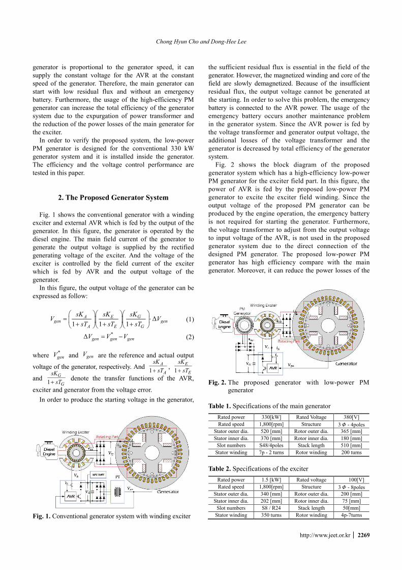
Fig. 3 shows the mechanical structures of the proposed
generator system. As shown in Fig. 3, the proposed low-
power PM generator is additionally installed at the end of
generator. The stator winding of the proposed PM
generator is connected to the digital AVR. The output of the
digital AVR is connected to the exciter stator winding.
Then, the output voltage of the exciter is rectified by the
diode rectifier and connected to the rotor winding of the
main generator.
Table 3. Specifications of the PMG
Rated Power 300[W] Rated Voltage 135[V]
Rated Speed 1,800[rpm] Structure 3Φ –8poles
Stator Outer Dia. 250 [mm] Rotor Outer Dia. 185.9 [mm]
Stator Inner Dia. 189.8 [mm] Rotor Inner Dia. 124 [mm]
Slot numbers S24/16 poles Stack Length 20[mm]
Stator Windings 50 turns PM number 16
Main Generator
Exciter Designed PMG
Diode RectifierExciter
winding
Fan
Fig. 3. Structures of the proposed generator system
3. Analysis of the Designed System
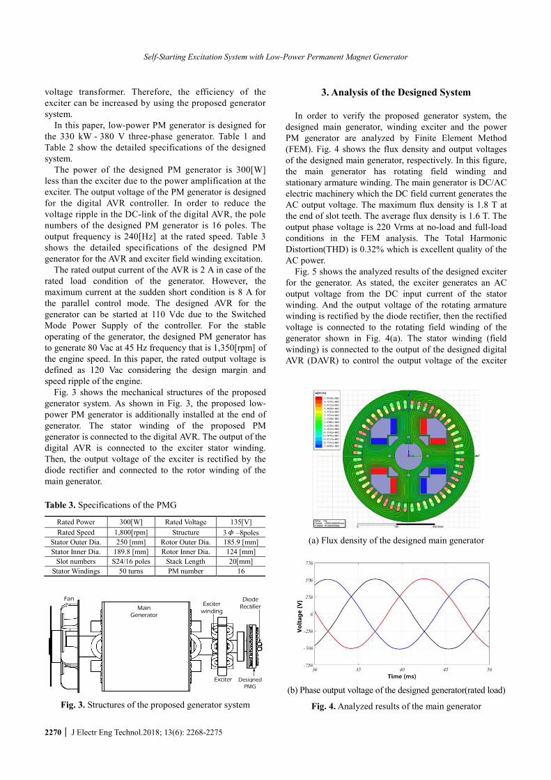
In order to verify the proposed generator system, the
designed main generator, winding exciter and the power
PM generator are analyzed by Finite Element Method
(FEM). Fig. 4 shows the flux density and output voltages
of the designed main generator, respectively. In this figure,
the main generator has rotating field winding and
stationary armature winding. The main generator is DC/AC
electric machinery which the DC field current generates the
AC output voltage. The maximum flux density is 1.8 T at
the end of slot teeth. The average flux density is 1.6 T. The
output phase voltage is 220 Vrms at no-load and full-load
conditions in the FEM analysis. The Total Harmonic
Distortion(THD) is 0.32% which is excellent quality of the
AC power.
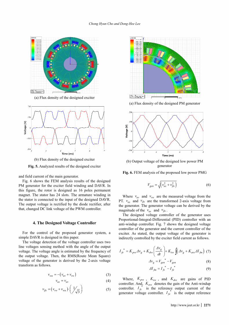
Fig. 5 shows the analyzed results of the designed exciter
for the generator. As stated, the exciter generates an AC
output voltage from the DC input current of the stator
winding. And the output voltage of the rotating armature
winding is rectified by the diode rectifier, then the rectified
voltage is connected to the rotating field winding of the
generator shown in Fig. 4(a). The stator winding (field
winding) is connected to the output of the designed digital
AVR (DAVR) to control the output voltage of the exciter
(a) Flux density of the designed main generator
(b) Phase output voltage of the designed generator(rated load)
Fig. 4. Analyzed results of the main generator
Chong Hyun Cho and Dong-Hee Lee
http://www.jeet.or.kr │ 2271
and field current of the main generator.
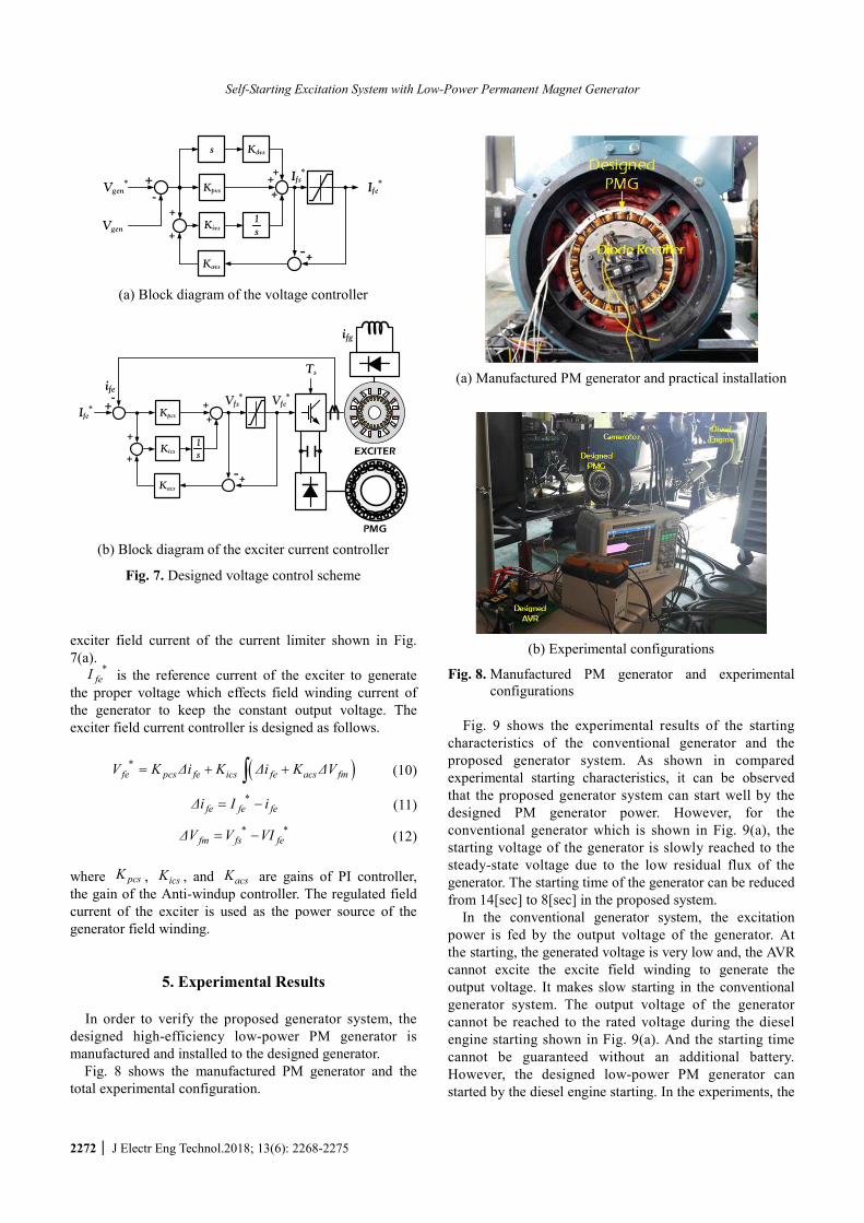
Fig. 6 shows the FEM analysis results of the designed
PM generator for the exciter field winding and DAVR. In
this figure, the rotor is designed as 16 poles permanent
magnet. The stator has 24 slots. The armature winding in
the stator is connected to the input of the designed DAVR.
The output voltage is rectified by the diode rectifier, after
that, changed DC link voltage of the PWM controller.
4. The Designed Voltage Controller For the control of the proposed generator system, a
simple DAVR is designed in this paper.
The voltage detection of the voltage controller uses two
line voltages sensing method with the angle of the output
voltage. The voltage angle is estimated by the frequency of
the output voltage. Then, the RMS(Route Mean Square)
voltage of the generator is derived by the 2-axis voltage
transform as follows.
( )wu uv vwv v v= − + (3)
αs uvv v= (4)
( ) 13
βs vw wuv v v = + ⋅
(5)
(a) Flux density of the designed PM generator
(b) Output voltage of the designed low power PM
generator
Fig. 6. FEM analysis of the proposed low power PMG
( )2 2gen αs βsV v v= + (6)
Where uvv and vwv are the measured voltage from the
PT. αsv and βsv are the transformed 2-axis voltage from
the generator. The generator voltage can be derived by the
magnitude of the αsv and βsv .
The designed voltage controller of the generator uses
Proportional-Integral-Differential (PID) controller with an
anti-windup controller. Fig. 7 shows the designed voltage
controller of the generator and the current controller of the
exciter. As stated, the output voltage of the generator is
indirectly controlled by the exciter field current as follows.
( )g*fe pvs g dvs ivs g avs fm
∆vI K ∆v K K ∆v K ∆I
dt
= + + +
∫ (7)
*
g gen gen∆v V V= − (8)
* *
fm fs fe∆I I I= − (9)
Where, pvsK , ivsK , and dvsK are gains of PID
controller. And, avsK denotes the gain of the Anti-windup
controller. *
fsI is the reference output current of the
generator voltage controller. *
feI is the output reference
(a) Flux density of the designed exciter
(b) Flux density of the designed exciter
Fig. 5. Analyzed results of the designed exciter
Self-Starting Excitation System with Low-Power Permanent Magnet Generator
2272 │ J Electr Eng Technol.2018; 13(6): 2268-2275
exciter field current of the current limiter shown in Fig.
7(a). *
feI is the reference current of the exciter to generate
the proper voltage which effects field winding current of
the generator to keep the constant output voltage. The
exciter field current controller is designed as follows.
( )*fe pcs fe ics fe acs fmV K ∆i K ∆i K ∆V= + +∫ (10)
*
fe fe fe∆i I i= − (11)
* *
fm fs fe∆V V VI= − (12)
where pcsK , icsK , and acsK are gains of PI controller,
the gain of the Anti-windup controller. The regulated field
current of the exciter is used as the power source of the
generator field winding.
5. Experimental Results
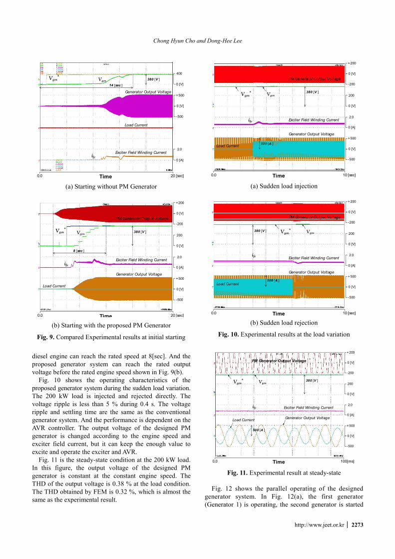
In order to verify the proposed generator system, the
designed high-efficiency low-power PM generator is
manufactured and installed to the designed generator.
Fig. 8 shows the manufactured PM generator and the
total experimental configuration.
(a) Manufactured PM generator and practical installation
(b) Experimental configurations
Fig. 8. Manufactured PM generator and experimental configurations
Fig. 9 shows the experimental results of the starting
characteristics of the conventional generator and the
proposed generator system. As shown in compared
experimental starting characteristics, it can be observed
that the proposed generator system can start well by the
designed PM generator power. However, for the
conventional generator which is shown in Fig. 9(a), the
starting voltage of the generator is slowly reached to the
steady-state voltage due to the low residual flux of the
generator. The starting time of the generator can be reduced
from 14[sec] to 8[sec] in the proposed system.
In the conventional generator system, the excitation
power is fed by the output voltage of the generator. At
the starting, the generated voltage is very low and, the AVR
cannot excite the excite field winding to generate the
output voltage. It makes slow starting in the conventional
generator system. The output voltage of the generator
cannot be reached to the rated voltage during the diesel
engine starting shown in Fig. 9(a). And the starting time
cannot be guaranteed without an additional battery.
However, the designed low-power PM generator can
started by the diesel engine starting. In the experiments, the
Kpvs
Kivs s1
Kavs
-+
+
+
Vgen* +
-Ife
*+
+
Vgen
Kdvss
+ Ifs*
(a) Block diagram of the voltage controller
Kpcs
Kics s1
Kacs
-+
+
+
+
+
ife
Ife* +- Vfe
*
Ts
EXCITER
PMG
ifg
Vfs*
(b) Block diagram of the exciter current controller
Fig. 7. Designed voltage control scheme
Chong Hyun Cho and Dong-Hee Lee
http://www.jeet.or.kr │ 2273
diesel engine can reach the rated speed at 8[sec]. And the
proposed generator system can reach the rated output
voltage before the rated engine speed shown in Fig. 9(b).
Fig. 10 shows the operating characteristics of the
proposed generator system during the sudden load variation.
The 200 kW load is injected and rejected directly. The
voltage ripple is less than 5 % during 0.4 s. The voltage
ripple and settling time are the same as the conventional
generator system. And the performance is dependent on the
AVR controller. The output voltage of the designed PM
generator is changed according to the engine speed and
exciter field current, but it can keep the enough value to
excite and operate the exciter and AVR.
Fig. 11 is the steady-state condition at the 200 kW load.
In this figure, the output voltage of the designed PM
generator is constant at the constant engine speed. The
THD of the output voltage is 0.38 % at the load condition.
The THD obtained by FEM is 0.32 %, which is almost the
same as the experimental result.
0.0 10 [sec]Time
+500
0 [V]
-500
Load Current
0 [A]
2.0
200
0 [V]
380 [V ]
+200
0 [V]
-200
Generator Output Voltage
ife Exciter Field Winding Current
PM Generator Output Voltage
VgenVgen*
500 [A ]
(a) Sudden load injection
0.0 10 [sec]Time
+500
0 [V]
-500
Load Current
0 [A]
2.0
200
0 [V]
380 [V ]
+200
0 [V]
-200
Generator Output Voltage
ifeExciter Field Winding Current
PM Generator Output Voltage
VgenVgen*
500 [A ]
(b) Sudden load rejection
Fig. 10. Experimental results at the load variation
0.0 100[ms]Time
+500
0 [V]
-500
Load Current
0 [A]
2.0
200
0 [V]
380 [V ]
+200
0 [V]
-200
Generator Output Voltage
VgenVgen*
ife Exciter Field Winding Current
PM Generator Output Voltage
500 [A ]
Fig. 11. Experimental result at steady-state
Fig. 12 shows the parallel operating of the designed
generator system. In Fig. 12(a), the first generator
(Generator 1) is operating, the second generator is started
0.0 20 [sec]Time
+500
0 [V]
-500
Load Current
0 [A]
2.0
380 [V ]
400
0 [V]
Generator Output Voltage
VgenVgen
*
ifeExciter Field Winding Current
14 [sec ]
(a) Starting without PM Generator
0.0 20 [sec]Time
+500
0 [V]
-500
Load Current
0 [A]
2.0
200
0 [V]
380 [V ]
+200
0 [V]
-200
Generator Output Voltage
VgenVgen
*
ifeExciter Field Winding Current
PM Generator Output Voltage
8 [sec ]
(b) Starting with the proposed PM Generator
Fig. 9. Compared Experimental results at initial starting
Self-Starting Excitation System with Low-Power Permanent Magnet Generator
2274 │ J Electr Eng Technol.2018; 13(6): 2268-2275
to adjust the output voltage and frequency together
afterwards. After the second diesel engine started, the
second generator can keep and adjust the output voltage
and frequency during the starting time of the diesel engine
as shown in Fig. 12(a). In Fig. 12(b), the sudden load is
changed from 200 to 100 kW at the parallel operating
condition. It can be seen that the voltage ripple is less than
2 % and lower than the stand-alone case which is shown
in Fig. 10 due to the parallel load burden. In the parallel
operating, the constant output voltage is well kept by using
the proposed generator system without the circular current
between two generators.
Because of the rotating characteristics, the actual
efficiency of the designed PM generator cannot be directly
measured. The total efficiency of the generator is tested in
the conventional generator system which has PT. And the
efficiency of the proposed system is compared to the
conventional system. Table 4 denotes the tested efficiencies
of two generator system according to the load conditions.
In the tests, the main generator and the exciter are the same.
In the proposed system, only the designed PM generator is
installed and PT is removed in the generator. As shown in
Table 4, the efficiency of the proposed generator system is
almost same as the conventional generator system. But, the
additional PT and starting battery can be removed in the
proposed generator system with fast starting characteristics.
6. Conclusions
In this paper, a high-efficiency low-power PM generator
has been presented to improve the starting characteristics
of the generator. Compared with the conventional generator,
the emergency battery and power transformer for the AVR
have been removed, so that the total system is simple than
the conventional generator system. Because of the low-
power PM generator, the total efficiency is almost same,
but the starting time without an additional battery is
reduced from 14[sec] to 8[sec] which is same as diesel
engine starting time. The power supply for the AVR has
been replaced by the proposed low-power PM generator.
Because the AVR can operate by the proper voltage of the
designed low-power PM generator, the emergency battery
is not required. From the experimental results, the
proposed system has better starting characteristics with
stable load variation and parallel operating condition.
Acknowledgements
This research was supported by The Future Planning
(NRF-2016H1D5A1910536) and “Human Resources
Program in Energy Technology” of the Korea Institute of
Energy Technology Evaluation and Planning (KETEP),
granted financial resource from the Ministry of Trade,
Industry & Energy, Republic of Korea. (No. 20164010200940)
and Basic Science Research Program through the National
Research Foundation of Korea(NRF) funded by the
Ministry of Education(NRF-2018R1D1A1B07043989).
References
[1] S. Nuzzo, M. Calea, C. Gerada, N. Brown, “Analysis,
Modeling, and Design Considerations for the Excitation
Systems of Synchronous Generators,” IEEE Trans.
on Industrial Electronics, vol. 65, no. 4, pp. 2996-
3007, 2018.
[2] Selami Kesler, Tayyip L. Doser, “A Voltage Regulation
System for Independent Load Operation of Stand
0.0 40 [sec]Time
+500
0 [V]
-500
Load Current
0 [A]
2.0
0 [V]
380 [V ]
400
0 [V]
Output Voltage of Generator -2
ife2Exciter Field Winding Current
VgenVgen*
Output Voltage of Generator -1+500
(a) Starting of parallel operating
0.0 40 [sec]Time
+500
0 [V]
-500
Load Current
0 [A]
2.0
0 [V]
380 [V ]
0 [V]
Output Voltage of Generator -2
ife2 Exciter Field Winding Current
Output Voltage of Generator -1+500
400
VgenVgen*
500 [A ]/ div
(b) Load variation in the parallel operating
Fig. 12. Experimental result of parallel operating
Table 4. Experimental efficiency
Load conditions 22% 52% 100%
Conventional Generator 93.80 96.84 97.01
Proposed Generator 93.81 96.84 97.02
Chong Hyun Cho and Dong-Hee Lee
http://www.jeet.or.kr │ 2275
Alone Self-Excited Induction Generators,” JOURNAL
OF POWER ELECTRONICS, vol. 16, no. 5, Sept.
2016, pp. 1869-1883.
[3] YeonJun Jo, Jin-Woo Ahn, Dong-Hee Lee, “Control
of a High Efficiency Generator with Exciter using
Frequency Weight Factor,” 2017 20th Internal Con-
ference on Electrical Machines and Systems(ICEMS),
pp. 1-6, 2017.
[4] E. Rebollo, C. A. Platero, F. Blazquez, R. Granizo,
“Internal Sudden Short-circuit Response of a New
HSBDS for Brushless Synchronous Machines Tested
on a 15 MVA Generator,” IET Electric Power Appli-
cations, vol. 11, no. 4, pp. 495-503, 2017.
[5] J. K. Noland, F. Evestedt, J. J. Perez-Loya, J.
Abrahamsson, U. Lundin, “Design and Characteri-
zation of a Rotating Brushless Outer Pole PM Exciter
for a Synchronous Generator,” IEEE Trans. on Industry
Applications, vol. 53, no. 3, pp. 2016-2027, 2017.
[6] J. K. Noland, F. Evestedt, J. J. Perez-Loya, J.
Abrahamsson, U. Lundin, “Comparison of Thyristor
Rectifier Configurations for a Six-Phase Rotating
Brushless Outer Pole PM Exciter,” IEEE Trans. on
Industrial Electronics, vol. 65, no. 2, pp. 968-976,
2018.
[7] J. K. Noland, K. B. Hjelmervik, U. Lundin,
“Comparison of Thyristor-Controlled Rectification
Topologies for a Six-Phase Rotating Brushless
Permanent Magnet Exciter,” IEEE Trans. on Energy
Conversion, vol. 31, no. 1, pp. 314-322, 2016.
[8] J. K. Noland, F. Evestedt, J. J. Perez-Loya, J.
Abrahamsson, U. Lundin, “Testing of Active Rectifi-
cation Topologies on a Six-Phase Rotating Brushless
Outer Pole PM Exciter,” IEEE Trans. on Energy
Conversion, vol. 33, no. 1, pp. 59-67, 2018.
[9] S. Zhu, C. Liu, K. Wang, Y. Hu, Y. Ning, “Theoretical
and Experimental Analyses of a Hybrid Excitation
Synchronous Generator with Integrated Brushless
Excitation,” IET Electric Power Applications, vol. 10,
no. 4, pp. 258-267, 2016.
[10] Z. Zhang, Y. Liu, B. Tian, W. Wang, “Investigation
and Implementation of a New Hybrid Excitation
Synchronous Machine Drive System,” IET Power
Applications, vol. 11, no. 4, pp. 487-494, 2017.
[11] F. Yao, Q. An, X. Gao, L. Sun, T. A. Lipo, “Principle
of Operation and Performance of a Synchronous
Machine Employing a New Harmonic Excitation
Scheme,” IEEE Trans. on Industry Applications, vol.
51, no. 5, pp. 3890-3898, 2015.
[12] F. Yao, Q. An, L. Sun, T. A. Lipo, “Performance
Investigation of a Brushless Synchronous Machine
With Additional Harmonic Field Windings,” IEEE
Trans. on Industrial Electronics, vol. 63, no. 11, pp.
6756-6766, 2016.
[13] N. Jiao, W. Liu, Z. Zhang, T. Meng, J. Peng, Y.
Jiang, “Field Current Estimation for Wound-Rotor
Synchronous Starter-Generator With Asynchronous
Brushless Exciters,” IEEE Trans. on Energy Con-
version, vol. 32, no. 4, pp. 1554-1561, 2017.
[14] N. Jiao, W. Liu, T. Meng, J. Peng, S. Mao, “Design
and Control of a Two-Phase Brushless Exciter for
Aircraft Wound-Rotor Synchronous Starter/Generator
in the Starting Mode,” IEEE Trans. on Power
Electronics, vol. 31, no. 6, pp. 4452-4461, 2016.
[15] N. Jiao, W. Liu, Z. Zhang, T. Meng, J. Peng, S. Mao,
“Detailed Excitation Control Methods for Two-Phase
Exciter of the Wound-Rotor Synchronous Starter/
Generator in the Starting Mode,” IEEE Trans. on
Industry Applications, vol. 53, no. 1, pp. 115-123,
2017.
[16] A. Griffo, R. Wrobel, P. H. Mellor, J. M. Yon,
“Design and Characterization of a Three-Phase
Brushless Exciter for Aircraft Starter/Generator,”
IEEE Trans. on Industry Applications, vol. 49, no. 5,
pp. 2016-2115, 2013.
Chong Hyun Cho He was born on May 4, 1979 and received his B.S.,
M.S., and Ph.D. degrees in Aerospace
Engineering from Gyeongsang National
University, Jinju, Korea, in 2004, 2006,
and 2010, respectively. He worked as
Korea Institute of Industrial Technology
(KITECH) from 2010 to 2013. Since
2013 he has been with Suntech Co. LTD, Suncheon, Korea,
as CTO. His major research field is the high efficiency
generator and renewable energy
Dong-Hee Lee He was born on November 11, 1970 and received his
B.S., M.S., and Ph.D. degrees in
Electrical Engineering from Pusan
National University, Busan, Korea, in
1996, 1998, and 2001, respectively. He
worked as a senior researcher of the
Servo R&D Team at OTIS-LG from
2002 to 2005. Since 2005, he has been with Kyungsung
University, Busan, Korea, as a professor in the Department
of Mechatronics Engineering. His major research field is
the high efficiency generator and electrical motor drive
with power electronics.