Embed Size (px)
Citation preview
PR
www.advmat.de
OGRESS
Semiconducting Thienothiophene Copolymers: Design,Synthesis, Morphology, and Performance in Thin-FilmOrganic Transistors
REPORT
By Iain McCulloch,* Martin Heeney,* Michael L. Chabinyc,*
Dean DeLongchamp,* R. Joseph Kline, Michael Colle, Warren Duffy,
Daniel Fischer, David Gundlach, Behrang Hamadani, Rick Hamilton,
Lee Richter, Alberto Salleo, Maxim Shkunov, David Sparrowe, Steven Tierney,
and Weimin Zhang
Organic semiconductors are emerging as a viable alternative to amorphous
silicon in a range of thin-film transistor devices. With the possibility to
formulate these p-type materials as inks and subsequently print into pat-
terned devices, organic-based transistors offer significant commercial
advantages for manufacture, with initial applications such as low perform-
ance displays and simple logic being envisaged. Previous limitations of both
air stability and electrical performance are now being overcome with a range
of both small molecule and polymer-based solution-processable materials,
which achieve charge carrier mobilities in excess of 0.5 cm2 V–1 s–1, a
benchmark value for amorphous silicon semiconductors. Polymer semi-
conductors based on thienothiophene copolymers have achieved amongst
the highest charge carrier mobilities in solution-processed transistor devices.
In this Progress Report, we evaluate the advances and limitations of this class
of polymer in transistor devices.
1. Introduction
Transistors are employed as the switching or amplifyingcomponents of almost all forms of integrated circuitry, and arethe key element of modern electronics.[1] Manufacture involves
[*] Prof. I. McCulloch, Dr. R. HamiltonDepartment of ChemistryImperial College, London, SW7 2AZ (UK)E-mail: [email protected]
Dr. M. HeeneyDepartment of MaterialsQueen Mary University of London, London, E1 4NS (UK)E-mail: [email protected]
Prof. M. L. ChabinycUniversity of California, Santa Barbara, 93106-5050 (USA)E-mail: [email protected]
DOI: 10.1002/adma.200801650
Dr. D. DeLongchamDr. B. Hamadani,National InstituteGaithersburg, MDE-mail: dean.delon
Dr. M. Colle, Dr. WDr. W. ZhangMerck ChemicalsChilworth Science
Prof. A. SalleoStanford University
Dr. M. ShkunovUniversity of Surre
Adv. Mater. 2009, 21, 1–19 � 2009 WILEY-VCH Verlag GmbH & Co. KGaA, Weinheim
material deposition and patterning using aseries of high-temperature, high-vacuumprocesses with lithographic patterning andmask steps. Although the high circuitdensity makes the cost per transistorextremely low, the cost per unit arearemains high, and alternative processingand new materials have been a focus forcost reduction and ease of processing,especially at large areas.[2–4] Migrating toflexible circuitry will likely require lowerprocessing temperatures, compatible withplastic substrates additionally driving theintroduction of new materials.[5] To accom-modate these requirements, transistorscomposed of organic semiconductors,which can be printed from solution, haveemerged as a promising possibility.[6–9]
Organic transistors are typically p-typefield-effect devices, operating in the accu-
mulation mode. Holes are injected into the highest occupiedmolecular orbital (HOMO) energy level of the organic semi-conductor and can be transported between the source and drainelectrodes, modulated by the gate electrode, which is insulatedfrom the accumulation channel by an organic dielectric layer. The
p, Dr. R. J. Kline, Dr. D. Fischer, Dr. D. Gundlach,Dr. L. Richterof Standards and Technology20899 (USA)[email protected]
. Duffy, Dr. D. Sparrowe, Dr. S. Tierney,
Park, Southampton, SO167QD (UK)
, Palo Alto, CA 94305 (USA)
y, Guilford, GU2 7XH (UK)
1

PROGRESS
REPORT
www.advmat.de
Iain McCulloch is Professor of Polymer Materials in the Department of Chemistry at Imperial CollegeLondon and co-founder of Flexink Ltd. His research interests are in the design, synthesis, andapplication of conjugated materials for optical and electronic applications. He obtained a PhD inPolymer Chemistry in 1989 at the University of Strathclyde, then joined Hoechst Celanese to engagein the research of novel functional polymers for nonlinear optics, lithography, and drug delivery. Hewas a Research Manager at Merck Chemicals from 2000 to 2007, responsible for novel organicsemiconductor materials for application in organic field-effect transistors and photovoltaic devices.
Martin Heeney is a senior lecturer in the Materials Department at Queen Mary University of London.He obtained his PhD in chemistry from the University of East Anglia (1999). Prior to his currentappointment, he was the chemistry team leader for the organic electronics group at Merck Chemical.His research interests include the development and characterization of novel materials for a variety ofoptoelectronic and sensing applications. He is co-founder and director of Flexink Ltd., a technologystart-up company commercializing organic semiconductor materials.
Michael L. Chabinyc is an Associate Professor in the Materials Department at the University ofCalifornia, Santa Barbara. He received his Ph.D. in chemistry from Stanford University (1999) andwas an N.I.H. post-doctoral fellow at Harvard University (2001). He was a senior research staffmember in the Electronic Materials and Devices Laboratory at Palo Alto Research Center beforemoving to UCSB. His current research focuses on semiconducting polymers for printed electronicsand energy conversion.
Dean M. DeLongchamp leads the Organic Electronics and Photovoltaics project in the PolymersDivision at the National Institute of Standards and Technology (NIST). He received a Ph. D. inChemical Engineering from MIT in 2003 for the development of functional self-assembled polymerfilms with applications in displays, batteries, and fuel cells. His current research is focused onunderstanding the relationship between device function and nanoscale interfacial structure at organicsemiconductor interfaces with advanced measurement methods such as soft X-ray spectroscopy andneutron reflectivity.
2 � 2009 WILEY-VCH Verlag GmbH & Co. KGaA, Weinheim Adv. Mater. 2009, 21, 1–19
PROGRESS
REPORT
www.advmat.de
electrical performance of the transistor is typically described interms of the semiconductor charge carrier mobility and thecurrent ON/OFF ratio. Both the current that can be delivered bythe transistor and the charging speed depend on the semi-conductor charge carrier mobility, and each application will have aminimum mobility requirement for optimal operation.[6,10]
Low-performance displays are likely to be the first applicationfor organic transistors, particularly electrophoretic displays onplastic substrates,[11] with low-resolution and sub-video refreshrates. As the electrophoretic display effect is reflective, thetransistor can occupy a large fraction of the area underneaththe pixel electrode area, thus enabling larger transistor electrodewidths (W) and correspondingly larger currents, hence requiringlower charge carrier mobilities, which are further relaxed by thelow display refresh rates. Indeed, early products have mobilityrequirements of lower than 0.1 cm2 V�1 s�1, well within thecapability of both small molecule and polymer semiconductors.Although early applications can be served by currently availablesemiconductor materials, future demand for more complex andhigher performing circuitry, enabling high-resolution, video-ratedisplays will require organic semiconductors with improvedcharge carrier mobility.[12] Both small molecule and polymersemiconductor transistors have been shown to depend onachieving a highly crystalline thin-film microstructure, withcrystalline domains well connected and aligned together. Withinthe domains the semiconductor molecules pack closely togetherwith their p conjugated aromatic rings linked in a planarconformation, allowing efficient intermolecular charge transfer.Successful organic transistorsmust be reliable over the lifetime ofthe application, and therefore good environmental stability isrequired. Most organic p-type semiconductors have electron-richHOMO energy levels and often exhibit oxidative doping in thepresence of ambient air and humidity. Current challengesare therefore to achieve both excellent electrical performancecombined with ambient stability. While the charge carriermobility in organic semiconductors is considered to bedependent on its molecular organization at the interface withthe dielectric, it has also been shown to be manipulated byvariables such as the polarity of the dielectric interface,[13,14]
the electrical field across the accumulation channel,[15,16] and thework function of the injecting electrodes.[17] Thus, it can beconsidered to be a figure of merit related to the transistorconfiguration as much as an intrinsic property of thesemiconductor. Standardizing device architecture and measure-ment technique is therefore important for accurate comparisonsto be obtained between semiconductor materials. Both solution-processable small molecule and polymer semiconductors havebeen widely developed, and in both cases high mobilitytransistors have been achieved. The focus of this report is toreview the design, characterization, and optimization ofthienothiophene copolymers, a promising class of solution-processable organic semiconductor, and their application intransistor devices.
2. Polymer Semiconductors
Polymeric semiconductors typically comprise coupled aromaticmonomer units, with extended p orbital conjugation along the
Adv. Mater. 2009, 21, 1–19 � 2009 WILEY-VCH Verlag Gmb
length of the backbone. Solubility is induced through theattachment of aliphatic side units projecting from the backbone,giving rise to the term ‘‘hairy rod’’ to describe polymerconformation. Both the polymer molecular weight and poly-dispersity are important properties to optimize, as they influencethe formulation rheology, as well as the thin film formation andmorphology from solution printing or casting. Low molecularweight polymer can often arise from both unoptimized syntheticprocesses as well as low levels of solubility in polymerizationsolvents, and thus resulting in precipitation from solution andpreventing extended chain growth. As the thermal properties andcrystallinity are sensitive tomolecular weight in the lowmolecularweight regime, it is also necessary to ensure that the molecularweight is above a rough threshold value beyond which point thephysical properties tend to stabilize. This value is likely to bepolymer-specific, but for most thiophene ‘‘hairy rod’’ polymers, anumber average molecular weight value of about 20 kDa is areasonable estimate of this threshold.[18] A motivating feature forthe use of polymer materials, are that they can be solution coatedinto cohesive and conformal thin films. Control of film thicknessand morphology can be achieved by optimization of solutionrheology and thermal properties. Fabrication of multilayer stacksfrom solution deposition processes requires that each layerdeposited is inert to the solvents and temperatures that it issubsequently exposed to during manufacture of the device. Thenarrow solubility parameter window of polymers, and their highbulk viscosity, typically increases the orthogonality options forsolution deposition on top of polymer layers, thus expanding thechoice of materials that can be used in devices. With negligiblevapor pressure, polymers are not susceptible to interlayerdiffusion during the typical device-fabrication thermal cycles,and typically exhibit robust mechanical properties, making thinsemiconductor films potentially compatible with flexible proces-sing or rollable substrate operation. As typical polymer crystallinedomain sizes are much smaller that the length scale of thetransistor channel dimensions, relatively isotropic in-planetransport occurs in transistor devices. This results in lowdevice-to-device performance variability, which is particularlyimportant where a larger number of transistors are required to beintegrated.
3. Polythiophenes
Thiophene-containing polymers have exhibited amongst thehighest charge carrier mobilities from field-effect transistorsfabricated by solution deposition.[19–21] When thiophenes arecoupled together in their 2nd and 5th positions, an extendeddelocalized electronic orbital system can be achieved in which theelectron-rich thiophene rings are conjugated together and exhibita coplanar conformation. This conformation provides themolecular template for achieving a highly crystalline thin-filmmicrostructure, which plays a role in their excellent chargetransport properties. The first semiconducting polymer to exhibitcharge carrier mobilities in the 0.1 cm2 V�1 s�1 range wasregioregular poly(3-hexylthiophene) (P3HT)[20] which was foundto be essential to achieve a highly crystalline microstructure andgood electrical performance. P3HT has emerged as a benchmarksemiconducting polymer due to its ready availability and ease of
H & Co. KGaA, Weinheim 3
PROGRESS
REPORT
www.advmat.de
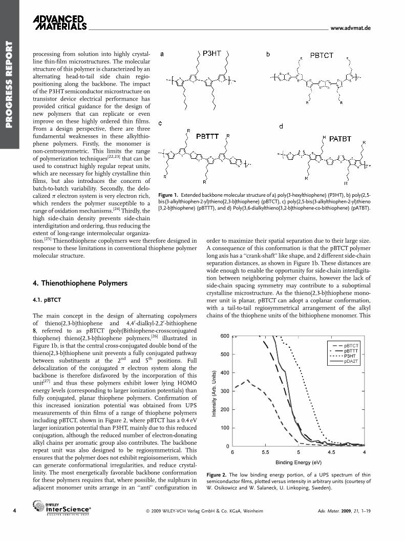
Figure 1. Extended backbonemolecular structure of a) poly(3-hexylthiophene) (P3HT), b) poly(2,5-bis(3-alkylthiophen-2-yl)thieno[2,3-b]thiophene) (pBTCT), c) poly(2,5-bis(3-alkylthiophen-2-yl)thieno[3,2-b]thiophene) (pBTTT), and d) Poly(3,6-dialkylthieno[3,2-b]thiophene-co-bithiophene) (pATBT).
4
processing from solution into highly crystal-line thin-film microstructures. The molecularstructure of this polymer is characterized by analternating head-to-tail side chain regio-positioning along the backbone. The impactof the P3HTsemiconductor microstructure ontransistor device electrical performance hasprovided critical guidance for the design ofnew polymers that can replicate or evenimprove on these highly ordered thin films.From a design perspective, there are threefundamental weaknesses in these alkylthio-phene polymers. Firstly, the monomer isnon-centrosymmetric. This limits the rangeof polymerization techniques[22,23] that can beused to construct highly regular repeat units,which are necessary for highly crystalline thinfilms, but also introduces the concern ofbatch-to-batch variability. Secondly, the delo-calized p electron system is very electron rich,which renders the polymer susceptible to arange of oxidationmechanisms.[24] Thirdly, thehigh side-chain density prevents side-chaininterdigitation and ordering, thus reducing theextent of long-range intermolecular organiza-
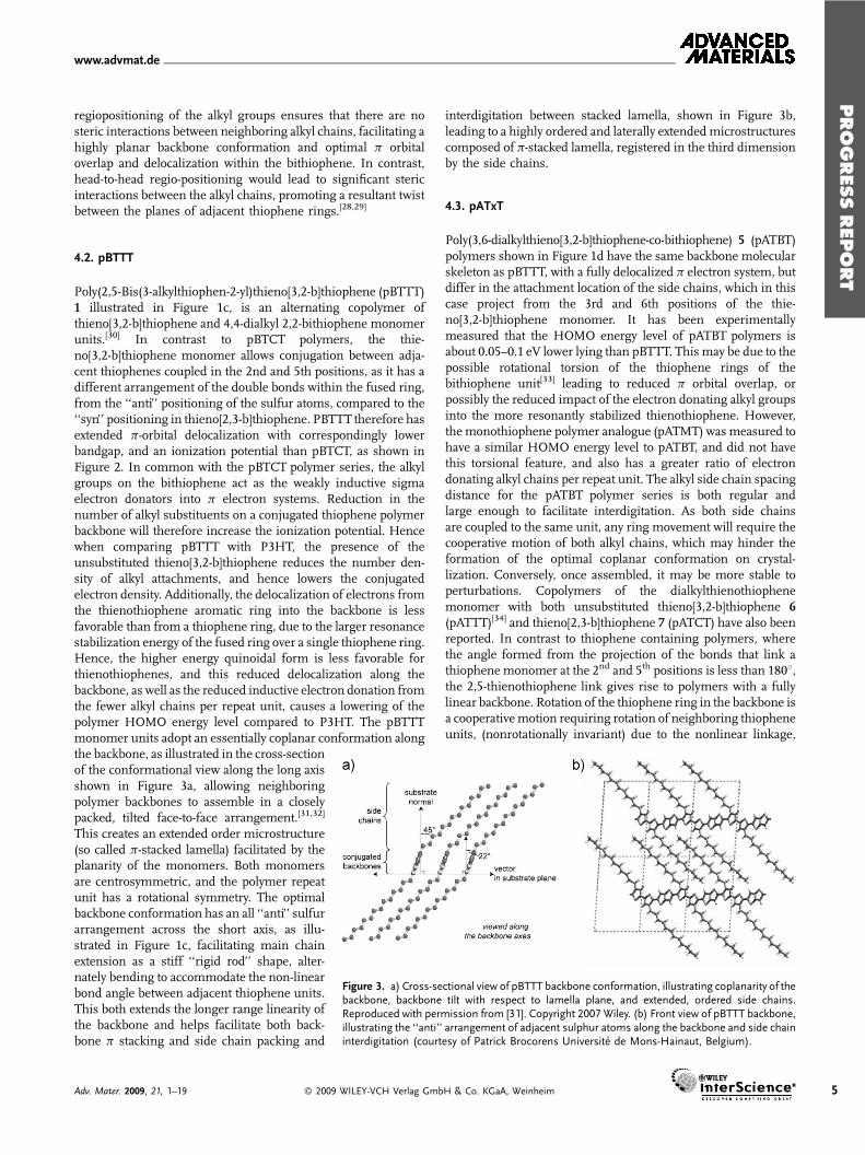
tion.[25] Thienothiophene copolymers were therefore designed inresponse to these limitations in conventional thiophene polymermolecular structure.Figure 2. The low binding energy portion, of a UPS spectrum of thinsemiconductor films, plotted versus intensity in arbitrary units (courtesy ofW. Osikowicz and W. Salaneck, U. Linkoping, Sweden).
4. Thienothiophene Polymers
4.1. pBTCT
The main concept in the design of alternating copolymersof thieno[2,3-b]thiophene and 4,40-dialkyl-2,20-bithiophene8, referred to as pBTCT (poly(Bithiophene-crossconjugatedthiophene) thieno[2,3-b]thiophene polymers,[26] illustrated inFigure 1b, is that the central cross-conjugated double bond of thethieno[2,3-b]thiophene unit prevents a fully conjugated pathwaybetween substituents at the 2nd and 5th positions. Fulldelocalization of the conjugated p electron system along thebackbone is therefore disfavored by the incorporation of thisunit[27] and thus these polymers exhibit lower lying HOMOenergy levels (corresponding to larger ionization potentials) thanfully conjugated, planar thiophene polymers. Confirmation ofthis increased ionization potential was obtained from UPSmeasurements of thin films of a range of thiophene polymersincluding pBTCT, shown in Figure 2, where pBTCT has a 0.4 eVlarger ionization potential than P3HT, mainly due to this reducedconjugation, although the reduced number of electron-donatingalkyl chains per aromatic group also contributes. The backbonerepeat unit was also designed to be regiosymmetrical. Thisensures that the polymer does not exhibit regioisomerism, whichcan generate conformational irregularities, and reduce crystal-linity. The most energetically favorable backbone conformationfor these polymers requires that, where possible, the sulphurs inadjacent monomer units arrange in an ‘‘anti’’ configuration in
� 2009 WILEY-VCH Verlag G
order to maximize their spatial separation due to their large size.A consequence of this conformation is that the pBTCT polymerlong axis has a ‘‘crank-shaft’’ like shape, and 2 different side-chainseparation distances, as shown in Figure 1b. These distances arewide enough to enable the opportunity for side-chain interdigita-tion between neighboring polymer chains, however the lack ofside-chain spacing symmetry may contribute to a suboptimalcrystalline microstructure. As the thieno[2,3-b]thiophene mono-mer unit is planar, pBTCT can adopt a coplanar conformation,with a tail-to-tail regiosymmetrical arrangement of the alkylchains of the thiophene units of the bithiophene monomer. This
mbH & Co. KGaA, Weinheim Adv. Mater. 2009, 21, 1–19
PROGRESS
REPORT
www.advmat.de
regiopositioning of the alkyl groups ensures that there are nosteric interactions between neighboring alkyl chains, facilitating ahighly planar backbone conformation and optimal p orbitaloverlap and delocalization within the bithiophene. In contrast,head-to-head regio-positioning would lead to significant stericinteractions between the alkyl chains, promoting a resultant twistbetween the planes of adjacent thiophene rings.[28,29]
4.2. pBTTT
Poly(2,5-Bis(3-alkylthiophen-2-yl)thieno[3,2-b]thiophene (pBTTT)1 illustrated in Figure 1c, is an alternating copolymer ofthieno[3,2-b]thiophene and 4,4-dialkyl 2,2-bithiophene monomerunits.[30] In contrast to pBTCT polymers, the thie-no[3,2-b]thiophene monomer allows conjugation between adja-cent thiophenes coupled in the 2nd and 5th positions, as it has adifferent arrangement of the double bonds within the fused ring,from the ‘‘anti’’ positioning of the sulfur atoms, compared to the‘‘syn’’ positioning in thieno[2,3-b]thiophene. PBTTT therefore hasextended p-orbital delocalization with correspondingly lowerbandgap, and an ionization potential than pBTCT, as shown inFigure 2. In common with the pBTCT polymer series, the alkylgroups on the bithiophene act as the weakly inductive sigmaelectron donators into p electron systems. Reduction in thenumber of alkyl substituents on a conjugated thiophene polymerbackbone will therefore increase the ionization potential. Hencewhen comparing pBTTT with P3HT, the presence of theunsubstituted thieno[3,2-b]thiophene reduces the number den-sity of alkyl attachments, and hence lowers the conjugatedelectron density. Additionally, the delocalization of electrons fromthe thienothiophene aromatic ring into the backbone is lessfavorable than from a thiophene ring, due to the larger resonancestabilization energy of the fused ring over a single thiophene ring.Hence, the higher energy quinoidal form is less favorable forthienothiophenes, and this reduced delocalization along thebackbone, as well as the reduced inductive electron donation fromthe fewer alkyl chains per repeat unit, causes a lowering of thepolymer HOMO energy level compared to P3HT. The pBTTTmonomer units adopt an essentially coplanar conformation along
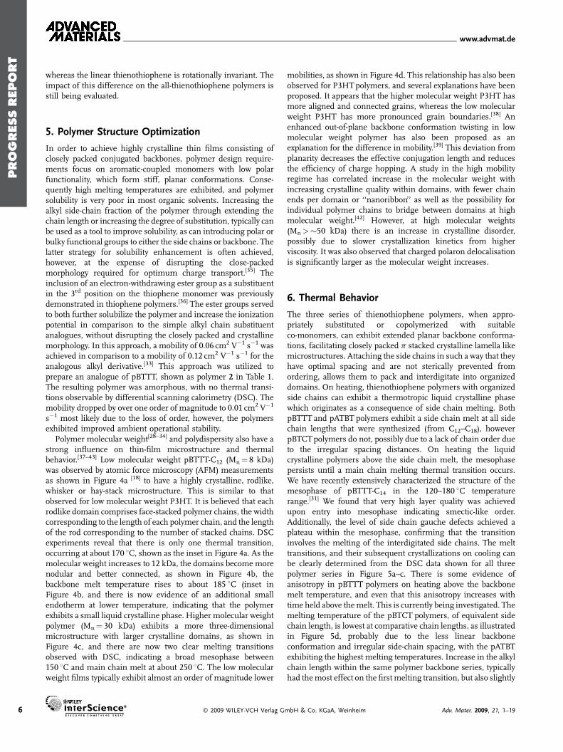
Figure 3. a) Cross-sectional view of pBTTT backbone conformation, illustrating coplanarity of thebackbone, backbone tilt with respect to lamella plane, and extended, ordered side chains.Reproduced with permission from [31]. Copyright 2007 Wiley. (b) Front view of pBTTT backbone,illustrating the ‘‘anti’’ arrangement of adjacent sulphur atoms along the backbone and side chaininterdigitation (courtesy of Patrick Brocorens Universite de Mons-Hainaut, Belgium).
the backbone, as illustrated in the cross-sectionof the conformational view along the long axisshown in Figure 3a, allowing neighboringpolymer backbones to assemble in a closelypacked, tilted face-to-face arrangement.[31,32]
This creates an extended order microstructure(so called p-stacked lamella) facilitated by theplanarity of the monomers. Both monomersare centrosymmetric, and the polymer repeatunit has a rotational symmetry. The optimalbackbone conformation has an all ‘‘anti’’ sulfurarrangement across the short axis, as illu-strated in Figure 1c, facilitating main chainextension as a stiff ‘‘rigid rod’’ shape, alter-nately bending to accommodate the non-linearbond angle between adjacent thiophene units.This both extends the longer range linearity ofthe backbone and helps facilitate both back-bone p stacking and side chain packing and
Adv. Mater. 2009, 21, 1–19 � 2009 WILEY-VCH Verlag Gmb
interdigitation between stacked lamella, shown in Figure 3b,leading to a highly ordered and laterally extendedmicrostructurescomposed of p-stacked lamella, registered in the third dimensionby the side chains.
4.3. pATxT
Poly(3,6-dialkylthieno[3,2-b]thiophene-co-bithiophene) 5 (pATBT)polymers shown in Figure 1d have the same backbone molecularskeleton as pBTTT, with a fully delocalized p electron system, butdiffer in the attachment location of the side chains, which in thiscase project from the 3rd and 6th positions of the thie-no[3,2-b]thiophene monomer. It has been experimentallymeasured that the HOMO energy level of pATBT polymers isabout 0.05–0.1 eV lower lying than pBTTT. This may be due to thepossible rotational torsion of the thiophene rings of thebithiophene unit[33] leading to reduced p orbital overlap, orpossibly the reduced impact of the electron donating alkyl groupsinto the more resonantly stabilized thienothiophene. However,the monothiophene polymer analogue (pATMT) was measured tohave a similar HOMO energy level to pATBT, and did not havethis torsional feature, and also has a greater ratio of electrondonating alkyl chains per repeat unit. The alkyl side chain spacingdistance for the pATBT polymer series is both regular andlarge enough to facilitate interdigitation. As both side chainsare coupled to the same unit, any ring movement will require thecooperative motion of both alkyl chains, which may hinder theformation of the optimal coplanar conformation on crystal-lization. Conversely, once assembled, it may be more stable toperturbations. Copolymers of the dialkylthienothiophenemonomer with both unsubstituted thieno[3,2-b]thiophene 6(pATTT)[34] and thieno[2,3-b]thiophene 7 (pATCT) have also beenreported. In contrast to thiophene containing polymers, wherethe angle formed from the projection of the bonds that link athiophene monomer at the 2nd and 5th positions is less than 1808,the 2,5-thienothiophene link gives rise to polymers with a fullylinear backbone. Rotation of the thiophene ring in the backbone isa cooperative motion requiring rotation of neighboring thiopheneunits, (nonrotationally invariant) due to the nonlinear linkage,
H & Co. KGaA, Weinheim 5
PROGRESS
REPORT
www.advmat.de
6
whereas the linear thienothiophene is rotationally invariant. Theimpact of this difference on the all-thienothiophene polymers isstill being evaluated.
5. Polymer Structure Optimization
In order to achieve highly crystalline thin films consisting ofclosely packed conjugated backbones, polymer design require-ments focus on aromatic-coupled monomers with low polarfunctionality, which form stiff, planar conformations. Conse-quently high melting temperatures are exhibited, and polymersolubility is very poor in most organic solvents. Increasing thealkyl side-chain fraction of the polymer through extending thechain length or increasing the degree of substitution, typically canbe used as a tool to improve solubility, as can introducing polar orbulky functional groups to either the side chains or backbone. Thelatter strategy for solubility enhancement is often achieved,however, at the expense of disrupting the close-packedmorphology required for optimum charge transport.[35] Theinclusion of an electron-withdrawing ester group as a substituentin the 3rd position on the thiophene monomer was previouslydemonstrated in thiophene polymers.[36] The ester groups servedto both further solubilize the polymer and increase the ionizationpotential in comparison to the simple alkyl chain substituentanalogues, without disrupting the closely packed and crystallinemorphology. In this approach, a mobility of 0.06 cm2 V�1 s�1 wasachieved in comparison to a mobility of 0.12 cm2 V�1 s�1 for theanalogous alkyl derivative.[33] This approach was utilized toprepare an analogue of pBTTT, shown as polymer 2 in Table 1.The resulting polymer was amorphous, with no thermal transi-tions observable by differential scanning calorimetry (DSC). Themobility dropped by over one order of magnitude to 0.01 cm2 V�1
s�1 most likely due to the loss of order, however, the polymersexhibited improved ambient operational stability.
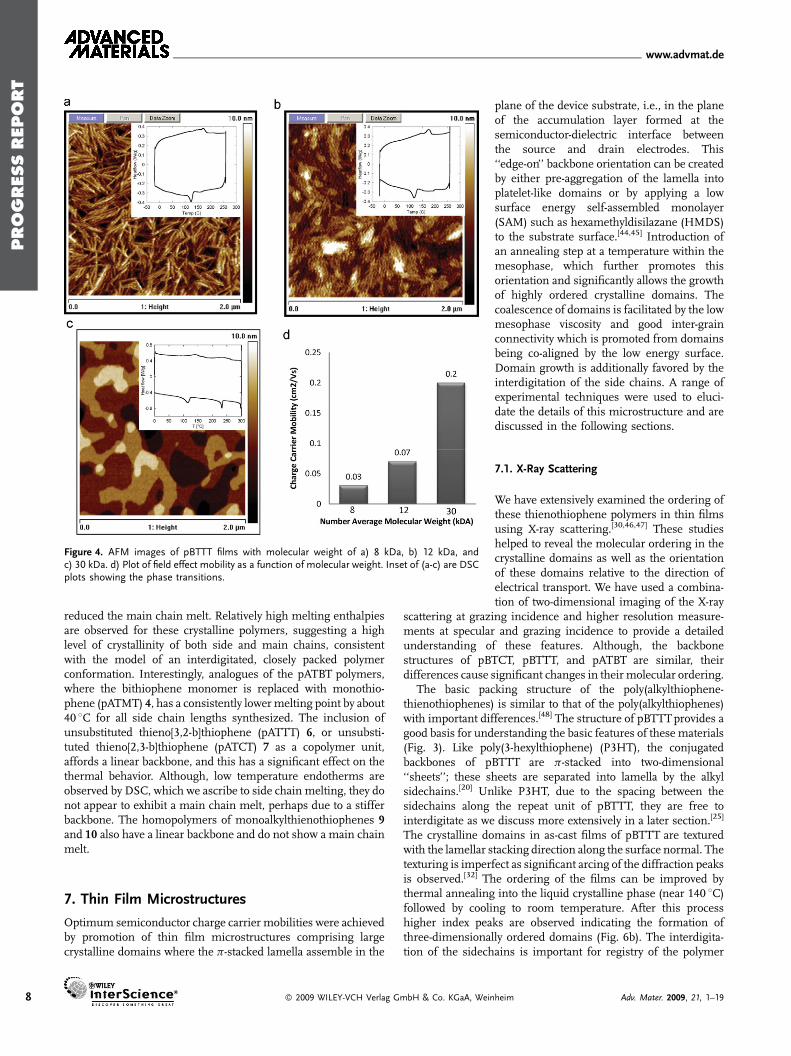
Polymer molecular weight[28–34] and polydispersity also have astrong influence on thin-film microstructure and thermalbehavior.[37–43] Low molecular weight pBTTT-C12 (Mn¼ 8 kDa)was observed by atomic force microscopy (AFM) measurementsas shown in Figure 4a [18] to have a highly crystalline, rodlike,whisker or hay-stack microstructure. This is similar to thatobserved for low molecular weight P3HT. It is believed that eachrodlike domain comprises face-stacked polymer chains, the widthcorresponding to the length of each polymer chain, and the lengthof the rod corresponding to the number of stacked chains. DSCexperiments reveal that there is only one thermal transition,occurring at about 170 8C, shown as the inset in Figure 4a. As themolecular weight increases to 12 kDa, the domains become morenodular and better connected, as shown in Figure 4b, thebackbone melt temperature rises to about 185 8C (inset inFigure 4b, and there is now evidence of an additional smallendotherm at lower temperature, indicating that the polymerexhibits a small liquid crystalline phase. Higher molecular weightpolymer (Mn¼ 30 kDa) exhibits a more three-dimensionalmicrostructure with larger crystalline domains, as shown inFigure 4c, and there are now two clear melting transitionsobserved with DSC, indicating a broad mesophase between150 8C and main chain melt at about 250 8C. The low molecularweight films typically exhibit almost an order of magnitude lower
� 2009 WILEY-VCH Verlag G
mobilities, as shown in Figure 4d. This relationship has also beenobserved for P3HTpolymers, and several explanations have beenproposed. It appears that the higher molecular weight P3HT hasmore aligned and connected grains, whereas the low molecularweight P3HT has more pronounced grain boundaries.[38] Anenhanced out-of-plane backbone conformation twisting in lowmolecular weight polymer has also been proposed as anexplanation for the difference in mobility.[39] This deviation fromplanarity decreases the effective conjugation length and reducesthe efficiency of charge hopping. A study in the high mobilityregime has correlated increase in the molecular weight withincreasing crystalline quality within domains, with fewer chainends per domain or ‘‘nanoribbon’’ as well as the possibility forindividual polymer chains to bridge between domains at highmolecular weight.[42] However, at high molecular weights(Mn>�50 kDa) there is an increase in crystalline disorder,possibly due to slower crystallization kinetics from higherviscosity. It was also observed that charged polaron delocalisationis significantly larger as the molecular weight increases.
6. Thermal Behavior
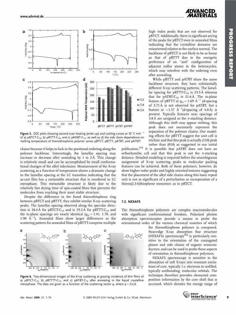
The three series of thienothiophene polymers, when appro-priately substituted or copolymerized with suitableco-monomers, can exhibit extended planar backbone conforma-tions, facilitating closely packed p stacked crystalline lamella likemicrostructures. Attaching the side chains in such a way that theyhave optimal spacing and are not sterically prevented fromordering, allows them to pack and interdigitate into organizeddomains. On heating, thienothiophene polymers with organizedside chains can exhibit a thermotropic liquid crystalline phasewhich originates as a consequence of side chain melting. BothpBTTT and pATBT polymers exhibit a side chain melt at all sidechain lengths that were synthesized (from C12–C18), howeverpBTCTpolymers do not, possibly due to a lack of chain order dueto the irregular spacing distances. On heating the liquidcrystalline polymers above the side chain melt, the mesophasepersists until a main chain melting thermal transition occurs.We have recently extensively characterized the structure of themesophase of pBTTT-C14 in the 120–180 8C temperaturerange.[31] We found that very high layer quality was achievedupon entry into mesophase indicating smectic-like order.Additionally, the level of side chain gauche defects achieved aplateau within the mesophase, confirming that the transitioninvolves the melting of the interdigitated side chains. The melttransitions, and their subsequent crystallizations on cooling canbe clearly determined from the DSC data shown for all threepolymer series in Figure 5a–c. There is some evidence ofanisotropy in pBTTT polymers on heating above the backbonemelt temperature, and even that this anisotropy increases withtime held above themelt. This is currently being investigated. Themelting temperature of the pBTCT polymers, of equivalent sidechain length, is lowest at comparative chain lengths, as illustratedin Figure 5d, probably due to the less linear backboneconformation and irregular side-chain spacing, with the pATBTexhibiting the highest melting temperatures. Increase in the alkylchain length within the same polymer backbone series, typicallyhad themost effect on the first melting transition, but also slightly
mbH & Co. KGaA, Weinheim Adv. Mater. 2009, 21, 1–19
PROGRESS
REPORT
www.advmat.de
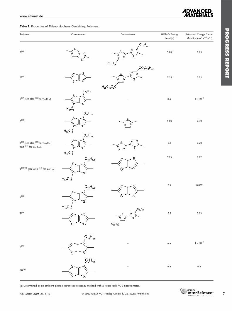
Table 1. Properties of Thienothiophene Containing Polymers.
Polymer Comonomer Comonomer HOMO Energy
Level [a]
Saturated Charge Carrier
Mobility [cm2 V�1 s�1]
1[30] 5.05 0.63
2[66] 5.25 0.01
3[67](see also [56] for C9H19) – n.a. 1� 10�6
4[68] 5.00 0.30
5[68](see also [69] for C15H31
and [34] for C9H19))
5.1 0.20
6[68,70] (see also [34] for C9H19)
5.25 0.02
7[68]
5.4 0.007
8[26] 5.3 0.03
9[71]– n.a. 3� 10�5
10[56]– n.a. n.a.
[a] Determined by an ambient photoelectron spectroscopy method with a Riken-Keiki AC-2 Spectrometer.
Adv. Mater. 2009, 21, 1–19 � 2009 WILEY-VCH Verlag GmbH & Co. KGaA, Weinheim 7
PROGRESS
REPORT
www.advmat.de
Figure 4. AFM images of pBTTT films with molecular weight of a) 8 kDa, b) 12 kDa, andc) 30 kDa. d) Plot of field effect mobility as a function of molecular weight. Inset of (a-c) are DSCplots showing the phase transitions.
8
reduced the main chain melt. Relatively high melting enthalpiesare observed for these crystalline polymers, suggesting a highlevel of crystallinity of both side and main chains, consistentwith the model of an interdigitated, closely packed polymerconformation. Interestingly, analogues of the pATBT polymers,where the bithiophene monomer is replaced with monothio-phene (pATMT) 4, has a consistently lowermelting point by about40 8C for all side chain lengths synthesized. The inclusion ofunsubstituted thieno[3,2-b]thiophene (pATTT) 6, or unsubsti-tuted thieno[2,3-b]thiophene (pATCT) 7 as a copolymer unit,affords a linear backbone, and this has a significant effect on thethermal behavior. Although, low temperature endotherms areobserved by DSC, which we ascribe to side chain melting, they donot appear to exhibit a main chain melt, perhaps due to a stifferbackbone. The homopolymers of monoalkylthienothiophenes 9and 10 also have a linear backbone and do not show a main chainmelt.
7. Thin Film Microstructures
Optimum semiconductor charge carrier mobilities were achievedby promotion of thin film microstructures comprising largecrystalline domains where the p-stacked lamella assemble in the
� 2009 WILEY-VCH Verlag GmbH & Co. KGaA, Wein
plane of the device substrate, i.e., in the planeof the accumulation layer formed at thesemiconductor-dielectric interface betweenthe source and drain electrodes. This‘‘edge-on’’ backbone orientation can be createdby either pre-aggregation of the lamella intoplatelet-like domains or by applying a lowsurface energy self-assembled monolayer(SAM) such as hexamethyldisilazane (HMDS)to the substrate surface.[44,45] Introduction ofan annealing step at a temperature within themesophase, which further promotes thisorientation and significantly allows the growthof highly ordered crystalline domains. Thecoalescence of domains is facilitated by the lowmesophase viscosity and good inter-grainconnectivity which is promoted from domainsbeing co-aligned by the low energy surface.Domain growth is additionally favored by theinterdigitation of the side chains. A range ofexperimental techniques were used to eluci-date the details of this microstructure and arediscussed in the following sections.
7.1. X-Ray Scattering
We have extensively examined the ordering ofthese thienothiophene polymers in thin filmsusing X-ray scattering.[30,46,47] These studieshelped to reveal the molecular ordering in thecrystalline domains as well as the orientationof these domains relative to the direction ofelectrical transport. We have used a combina-tion of two-dimensional imaging of the X-ray
scattering at grazing incidence and higher resolution measure-ments at specular and grazing incidence to provide a detailedunderstanding of these features. Although, the backbonestructures of pBTCT, pBTTT, and pATBT are similar, theirdifferences cause significant changes in their molecular ordering.
The basic packing structure of the poly(alkylthiophene-thienothiophenes) is similar to that of the poly(alkylthiophenes)with important differences.[48] The structure of pBTTTprovides agood basis for understanding the basic features of these materials(Fig. 3). Like poly(3-hexylthiophene) (P3HT), the conjugatedbackbones of pBTTT are p-stacked into two-dimensional‘‘sheets’’; these sheets are separated into lamella by the alkylsidechains.[20] Unlike P3HT, due to the spacing between thesidechains along the repeat unit of pBTTT, they are free tointerdigitate as we discuss more extensively in a later section.[25]
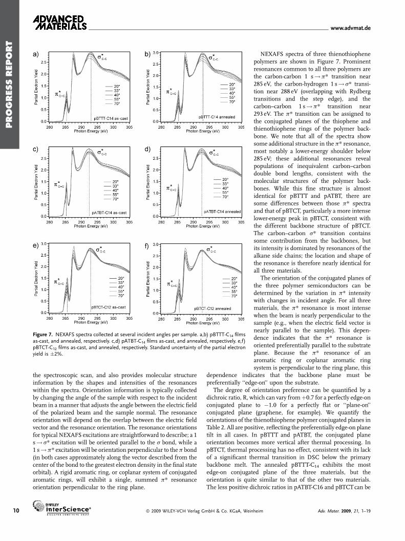
The crystalline domains in as-cast films of pBTTT are texturedwith the lamellar stacking direction along the surface normal. Thetexturing is imperfect as significant arcing of the diffraction peaksis observed.[32] The ordering of the films can be improved bythermal annealing into the liquid crystalline phase (near 140 8C)followed by cooling to room temperature. After this processhigher index peaks are observed indicating the formation ofthree-dimensionally ordered domains (Fig. 6b). The interdigita-tion of the sidechains is important for registry of the polymer
heim Adv. Mater. 2009, 21, 1–19
PROGRESS
REPORT
www.advmat.de
Figure 5. DSC plots showing second scan heating (endo up) and cooling curves at 10 8C min�1
of a) pBTCT-C10, b) pBTTT-C10, and c) pADBT-C14. as well as d) the side chain dependence onmelting temperature of thienothiophene polymer series pBTCT, pBTTT, pATBT, and pATMT.
chains because it helps to lock in the positional ordering along thepolymer backbone. Interestingly, the lamellar spacing mayincrease or decrease after annealing by 1 to 2 A. This changeis relatively small and can be accomplished by small conforma-tional changes of the alkyl sidechains. Measurement of the X-rayscattering as a function of temperature shows a dramatic changein the lamellar spacing at the LC transition indicating that theas-cast film has a metastable structure that is reordered in LCmesophase. This metastable structure is likely due to therelatively fast drying time of spin-coated films that prevents themolecules from reaching their most stable structure.
Despite the difference in the fused thienothiophene ringbetween pBTCT and pBTTT, they exhibit similar X-ray scatteringpeaks. The lamellar spacing observed along the specular direc-tion is 18.4 A for pBTCT-C12 and is 19.2 A for pBTTT-C12 andthe in-plane spacings are nearly identical (qxy¼ 1.41, 1.70, and1.90 A�1). Annealed films show larger differences as thescattering pattern for annealed films of pBTTTcomprise multiple
Figure 6. Two-dimensional images of the X-ray scattering at grazing incidence of thin films ofa) pBTCT-C12, b) pBTTTT-C12, and c) pATBT-C16 after annealing in the liquid crystallinemesophase. The data are given as a function of the scattering vector q, where q¼ 2p/d.
Adv. Mater. 2009, 21, 1–19 � 2009 WILEY-VCH Verlag GmbH & Co. KGaA, Weinhe
high index peaks that are not observed forpBTCT. Additionally, there is significant arcingof the peaks for pBTCTeven in annealed filmsindicating that the crystalline domains aremisoriented relative to the surface normal. Thebackbone of pBTCT is not likely to be as linearas that of pBTTT due to the energeticpreference of an ‘‘anti’’ configuration ofadjacent sulfur atoms in the heterocycles,which may interfere with the ordering evenafter annealing.
While pBTTT and pATBT share the samebackbone structure, they have substantiallydifferent X-ray scattering patterns. The lamel-lar spacing for pBTTT-C16 is 23.5 A whereasthat for pATBT-C16 is 21.6 A. The in-planefeature of pBTTT at qxy¼ 1.69 A�1 (d-spacingof 3.71 A is not observed for pATBT, but afeature at �1.57 A�1(d-spacing of 4.0 A) ispresent. Typically features near spacings of3.8 A are assigned as the p-stacking distance.Although this shift may appear striking, thispeak does not necessarily represent theseparation of the polymer chains. Our model-ing efforts for pBTTT suggest the unit cell istriclinic and that this peak is actually (110) peakrather than (010) as suggested in our initial
publication.[49] It is possible that pATBT does not have anorthorhombic cell and that this peak is not the p-stackingdistance. Detailed modeling is required before the unambiguousassignment of X-ray scattering peaks to molecular packingfeatures can be achieved. Both of these polymers, however, doshow higher order peaks and highly oriented textures suggestingthat the placement of the alkyl side chains along this basic repeatunit is not as significant of a perturbation as incorporation of athieno[2,3-b]thiophene monomer, as in pBTCT.
7.2. NEXAFS
The thienothiophene polymers are complex macromoleculeswith significant conformational freedom. Polarized photonabsorption spectroscopies provide a means to probe theorientational order of the various chemical moieties of which
the thienothiophene polymer is composed.Near-edge X-ray absorption fine structure(NEXAFS) spectroscopy[50] is particularly sen-sitive to the orientation of the conjugatedplanes and side chains of organic semicon-ductors, and can be used to probe these aspectsof orientation in thienothiophene polymers.
NEXAFS spectroscopy is sensitive to theabsorption of soft X-rays into resonant excita-tions of core, typically 1 s, electrons to unfilled,typically antibonding, molecular orbitals. Thetechnique therefore provides elemental com-position information by the core shell that isaccessed, which dictates the energy range of
im 9
PROGRESS
REPORT
www.advmat.de
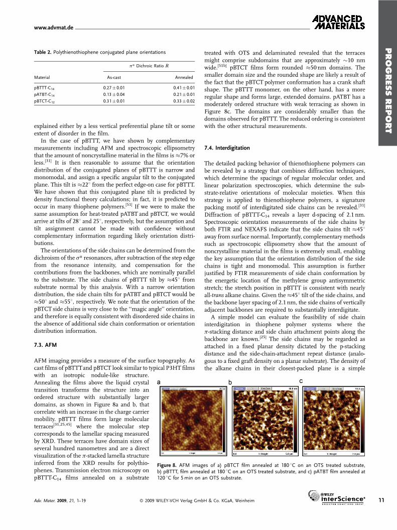
Figure 7. NEXAFS spectra collected at several incident angles per sample. a,b) pBTTT-C14 filmsas-cast, and annealed, respectively. c,d) pATBT-C14 films as-cast, and annealed, respectively. e,f)pBTCT-C12 films as-cast, and annealed, respectively. Standard uncertainty of the partial electronyield is �2%.
10
the spectroscopic scan, and also provides molecular structureinformation by the shapes and intensities of the resonanceswithin the spectra. Orientation information is typically collectedby changing the angle of the sample with respect to the incidentbeam in a manner that adjusts the angle between the electric fieldof the polarized beam and the sample normal. The resonanceorientation will depend on the overlap between the electric fieldvector and the resonance orientation. The resonance orientationsfor typical NEXAFS excitations are straightforward to describe; a 1s! s* excitation will be oriented parallel to the s bond, while a1 s!p* excitation will be orientation perpendicular to the p bond(in both cases approximately along the vector described from thecenter of the bond to the greatest electron density in the final stateorbital). A rigid aromatic ring, or coplanar system of conjugatedaromatic rings, will exhibit a single, summed p* resonanceorientation perpendicular to the ring plane.
� 2009 WILEY-VCH Verlag GmbH & Co. KGaA, Wein
NEXAFS spectra of three thienothiophenepolymers are shown in Figure 7. Prominentresonances common to all three polymers arethe carbon-carbon 1 s!p* transition near285 eV, the carbon-hydrogen 1 s! s* transi-tion near 288 eV (overlapping with Rydbergtransitions and the step edge), and thecarbon–carbon 1 s!p* transition near293 eV. The p* transition can be assigned tothe conjugated planes of the thiophene andthienothiophene rings of the polymer back-bone. We note that all of the spectra showsome additional structure in the p* resonance,most notably a lower-energy shoulder below285 eV; these additional resonances revealpopulations of inequivalent carbon–carbondouble bond lengths, consistent with themolecular structures of the polymer back-bones. While this fine structure is almostidentical for pBTTT and pATBT, there aresome differences between those p* spectraand that of pBTCT, particularly a more intenselower-energy peak in pBTCT, consistent withthe different backbone structure of pBTCT.The carbon–carbon s* transition containssome contribution from the backbones, butits intensity is dominated by resonances of thealkane side chains; the location and shape ofthe resonance is therefore nearly identical forall three materials.
The orientation of the conjugated planes ofthe three polymer semiconductors can bedetermined by the variation in p* intensitywith changes in incident angle. For all threematerials, the p* resonance is most intensewhen the beam is nearly perpendicular to thesample (e.g., when the electric field vector isnearly parallel to the sample). This depen-dence indicates that the p* resonance isoriented preferentially parallel to the substrateplane. Because the p* resonance of anaromatic ring or coplanar aromatic ringsystem is perpendicular to the ring plane, this
dependence indicates that the backbone plane must bepreferentially ‘‘edge-on’’ upon the substrate.
The degree of orientation preference can be quantified by adichroic ratio, R, which can vary fromþ0.7 for a perfectly edge-onconjugated plane to �1.0 for a perfectly flat or ‘‘plane-on’’conjugated plane (graphene, for example). We quantify theorientations of the thienothiophene polymer conjugated planes inTable 2. All are positive, reflecting the preferentially edge-on planetilt in all cases. In pBTTT and pATBT, the conjugated planeorientation becomes more vertical after thermal processing. InpBTCT, thermal processing has no effect, consistent with its lackof a significant thermal transition in DSC below the primarybackbone melt. The annealed pBTTT-C14 exhibits the mostedge-on conjugated plane of the three materials, but theorientation is quite similar to that of the other two materials.The less positive dichroic ratios in pATBT-C16 and pBTCTcan be
heim Adv. Mater. 2009, 21, 1–19
PROGRESS
REPORT
www.advmat.de
Table 2. Polythienothiophene conjugated plane orientations
p* Dichroic Ratio R
Material As-cast Annealed
pBTTT-C14 0.27� 0.01 0.41� 0.01
pATBT-C14 0.13� 0.04 0.21� 0.01
pBTCT-C12 0.31� 0.01 0.33� 0.02
explained either by a less vertical preferential plane tilt or someextent of disorder in the film.
In the case of pBTTT, we have shown by complementarymeasurements including AFM and spectroscopic ellipsometrythat the amount of noncrystalline material in the films is �7% orless.[31] It is then reasonable to assume that the orientationdistribution of the conjugated planes of pBTTT is narrow andmonomodal, and assign a specific angular tilt to the conjugatedplane. This tilt is �228 from the perfect edge-on case for pBTTT.We have shown that this conjugated plane tilt is predicted bydensity functional theory calculations; in fact, it is predicted tooccur in many thiophene polymers.[51] If we were to make thesame assumption for heat-treated pATBT and pBTCT, we wouldarrive at tilts of 288 and 258, respectively, but the assumption andtilt assignment cannot be made with confidence withoutcomplementary information regarding likely orientation distri-butions.
The orientations of the side chains can be determined from thedichroism of the s* resonances, after subtraction of the step edgefrom the resonance intensity, and compensation for thecontributions from the backbones, which are nominally parallelto the substrate. The side chains of pBTTT tilt by �458 fromsubstrate normal by this analysis. With a narrow orientationdistribution, the side chain tilts for pATBT and pBTCT would be�508 and �558, respectively. We note that the orientation of thepBTCT side chains is very close to the ‘‘magic angle’’ orientation,and therefore is equally consistent with disordered side chains inthe absence of additional side chain conformation or orientationdistribution information.
7.3. AFM
AFM imaging provides a measure of the surface topography. Ascast films of pBTTTand pBTCT look similar to typical P3HT films
Figure 8. AFM images of a) pBTCT film annealed at 180 8C on an OTS treated substrate,b) pBTTT, film annealed at 180 8C on an OTS treated substrate, and c) pATBT film annealed at120 8C for 5min on an OTS substrate.
with an isotropic nodule-like structure.Annealing the films above the liquid crystaltransition transforms the structure into anordered structure with substantially largerdomains, as shown in Figure 8a and b, thatcorrelate with an increase in the charge carriermobility. pBTTT films form large molecularterraces[31,25,45] where the molecular stepcorresponds to the lamellar spacing measuredby XRD. These terraces have domain sizes ofseveral hundred nanometres and are a directvisualization of the p-stacked lamella structureinferred from the XRD results for polythio-phenes. Transmission electron microscopy onpBTTT-C14 films annealed on a substrate
Adv. Mater. 2009, 21, 1–19 � 2009 WILEY-VCH Verlag Gmb
treated with OTS and delaminated revealed that the terracesmight comprise subdomains that are approximately �10 nmwide.[51b] pBTCT films form rounded �50 nm domains. Thesmaller domain size and the rounded shape are likely a result ofthe fact that the pBTCT polymer conformation has a crank shaftshape. The pBTTT monomer, on the other hand, has a moreregular shape and forms large, extended domains. pATBT has amoderately ordered structure with weak terracing as shown inFigure 8c. The domains are considerably smaller than thedomains observed for pBTTT. The reduced ordering is consistentwith the other structural measurements.
7.4. Interdigitation
The detailed packing behavior of thienothiophene polymers canbe revealed by a strategy that combines diffraction techniques,which determine the spacings of regular molecular order, andlinear polarization spectroscopies, which determine the sub-strate-relative orientations of molecular moieties. When thisstrategy is applied to thienothiophene polymers, a signaturepacking motif of interdigitated side chains can be revealed.[31]
Diffraction of pBTTT-C14 reveals a layer d-spacing of 2.1 nm.Spectroscopic orientation measurements of the side chains byboth FTIR and NEXAFS indicate that the side chains tilt �458away from surface normal. Importantly, complementary methodssuch as spectroscopic ellipsometry show that the amount ofnoncrystalline material in the films is extremely small, enablingthe key assumption that the orientation distribution of the sidechains is tight and monomodal. This assumption is furtherjustified by FTIR measurements of side chain conformation bythe energetic location of the methylene group antisymmetricstretch; the stretch position in pBTTT is consistent with nearlyall-trans alkane chains. Given the �458 tilt of the side chains, andthe backbone layer spacing of 2.1 nm, the side chains of verticallyadjacent backbones are required to substantially interdigitate.
A simple model can evaluate the feasibility of side chaininterdigitation in thiophene polymer systems where thep-stacking distance and side chain attachment points along thebackbone are known.[25] The side chains may be regarded asattached in a fixed planar density dictated by the p-stackingdistance and the side-chain-attachment repeat distance (analo-gous to a fixed graft density on a planar substrate). The density ofthe alkane chains in their closest-packed plane is a simple
H & Co. KGaA, Weinheim 11
PROGRESS
REPORT
www.advmat.de
12
function of their attachment density, the substrate-relative alkanechain tilt, and whether the side chains are interdigated (whichdoubles the density). Comparison of the density of the alkanechains in their closest-packed plane to the methylene density incrystalline polyethylene can be used to evaluate the feasibility ofinterdigitation. This analysis shows that the side chains of pBTTTwill achieve a polyethylene-like density when they are tilted at 458with respect to surface normal and interdigitation, consistentwith our experimental finding. This model also predicts that theside chains of pATBT and pBTCT are capable of interdigitation.The similar chain tilt and lamellar repeat observed for pATBT,together with preliminary IR and ellipsometry results, confirminterdigitation for that series. We cannot currently confirm thecase for pBTCT. Importantly, this model also shows that the sidechains of P3AT’s cannot interdigitate (at least for the mostcommon p-stacking distance of P3AT’s) because they are toodensely attached long the backbone. This key difference betweenpBTTT and P3HT may explain the greater three-dimensionalorder seen in pBTTT; side chain interdigitation provides amechanism for three-dimensional molecular registry. The simplemodel provides a framework for predicting whether a givenprimary chemical structure is capable of interdigitation. Themelting of the crystalline, interdigitated side chains provides amechanism for ‘‘repairing’’ defects in as-cast films by access tothe smectic-like mesophase where the side chain constraints areminimal and the backbones have sufficient molecular diffusivityto rearrange into large, well-ordered domains. The high levels oflayer order and domain size are locked-in upon cooling by theinterdigitation and crystallization of the side chains.
8. Transistor Properties
The p-type charge carrier mobility of thienothiophene polymerswas routinely determined in bottom-contact, bottom-gatefield-effect transistor devices (measurement details are providedin the General Experimental Methods section). This devicearchitecture is convenient as the semiconductor is only exposedto one thermal processing step, and high quality, readily availablepatterned substrates can be prepared separately. The techniquewas therefore developed as a routine screening method.The saturation regime mobility mSAT was calculated from thesaturation regime transfer characteristics using the equation:
ID ¼ WCi
2LmSAT V0 � VG½ �2 (1)
whereW is the transistor channel width, L the channel length, V0
the turn-on voltage, Vg the gate voltage, and mSAT was derived
from the slope of a plot of (ID)1/2 versus VG.
The charge carrier mobility values of a range of thienothio-phene polymers have been measured and are collected in Table 1.In several cases values approach that of high performing,evaporated small molecule devices[52] and are comparable toamorphous silicon. In general, mobilities were measured to behigher in inert atmosphere than ambient, perhaps due to thepresence of charge transfer complexes due to atmosphericimpurities, which may act as traps. Unless explicitly stated, thevalues reported were measured in nitrogen. Charge carrier
� 2009 WILEY-VCH Verlag G
mobilities of about 0.03 cm2 V�1 s�1 can be achieved by pBTCTpolymers, at standard channel lengths of 10–20mm, withcorresponding ON/OFF ratios around 106 in air. Higher chargecarrier mobilities of up to 0.1 cm2 V�1 s�1 were observed forshorter channel lengths of 5mm. The linearity of the outputcharacteristics at low source-drain voltages suggest that even withthe lower HOMO energy level, good charge injection from goldelectrodes is still possible. PBTTT polymers generally exhibitedthe highest mobilities of all thienothiophene polymers measured,with values of up to 0.6 cm2 V�1 s�1 obtained at a 20mm channellength for polymers with a C14 side chain length. In contrast toreported values for P3HT transistor devices,[53–55] there is lessthan a factor of two difference in charge carrier mobility forpBTTT polymers on varying the alkyl chain length from C10 toC18, with a maximum mobility observed at a chain length of C14.Charge carrier mobilities of up to 0.2 cm2 V�1 s�1 were measuredfor pATBT polymers in both air and nitrogen, demonstrating thestability of this polymer class. The monothiophene copolymer(pATMT) also exhibited high charge carrier mobility, in this caseup to 0.3 cm2 V�1 s�1 in a dry nitrogen atmosphere. Thisanalogue however was not as stable in ambient as the bithiophenepolymer even though the HOMO energy levels were measured tobe similar. Mobilities of 0.02 and 0.007 cm2 V�1 s�1 for co-polymers of dialkylthienothiophene with thieno[3,2-b]thiopheneanalogue 6, and thieno[2,3-b]thiophene analogue 7were obtained,respectively.
A regioregular homo polymer of 3-nonylthieno[3,2-b]thio-phene was also prepared (Table 1, 10); however, the molecularweight and solubility was low.[56] Charge transport characteristicswere not reported. The homo polymer of 3,6-dimethoxythieno[3,2-b]thiophene[57] and copolymers of 3,4-dialkoxythieno[2,3-b]thio-phene[58] have recently been reported as a possible alternative tothe conducting polymer ethylenedioxythiophene (PEDOT).
Copolymers of thieno[3,2-b]thiophene[59–61] and thieno[2,3-b]thiophene[62] with 9,9-dialkyl fluorene have also been reportedfor both transistor and OLED applications. In the case of thethieno[3,2-b]thiophene copolymer, the material exhibited thermo-tropic liquid crystalline behavior with a nematic phase at hightemperature.[63] Field effect mobilities in p-type transistor deviceswere on the order of 10�3 cm2 V�1 s�1. Although, the mobilityvalue is on the low side of acceptable performance, a comparisonto the well studied poly(9,9-dioctylfluorene-alt-bithiophene(F8T2)[64,65] under the same device conditions revealed slightlyhigher performance for the thieno[3,2-b]thiophene copolymer,demonstrating the potential for further optimization.
9. Low Contact Resistance Transistors
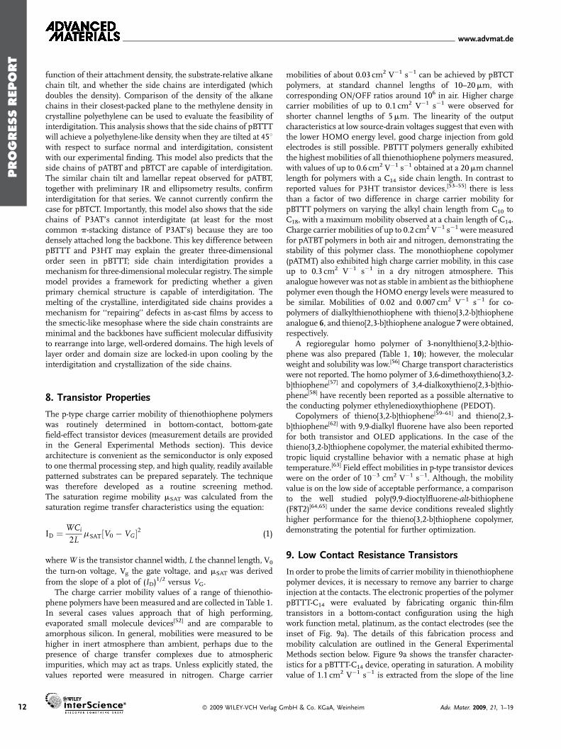
In order to probe the limits of carrier mobility in thienothiophenepolymer devices, it is necessary to remove any barrier to chargeinjection at the contacts. The electronic properties of the polymerpBTTT-C14 were evaluated by fabricating organic thin-filmtransistors in a bottom-contact configuration using the highwork function metal, platinum, as the contact electrodes (see theinset of Fig. 9a). The details of this fabrication process andmobility calculation are outlined in the General ExperimentalMethods section below. Figure 9a shows the transfer character-istics for a pBTTT-C14 device, operating in saturation. A mobilityvalue of 1.1 cm2 V�1 s�1 is extracted from the slope of the line
mbH & Co. KGaA, Weinheim Adv. Mater. 2009, 21, 1–19
PROGRESS
REPORT
www.advmat.de
Figure 9. a) Transfer characteristics of a pBTTT-C14 transistor at room temperature andVDS¼�60V. From the slope of the line shown and the given device parameters, we extractamobility of 1.1 cm2 V�1 s�1. Inset: Device cross section for a bottom-contact organic TFT. b) Plotof the saturation mobilities as a function of L for two sets of devices with different contactelectrodes. Devices fabricated with Pt electrodes make better contact to pBTTT and the mobilityshows a strong inverse L dependence.
shown in the plot, the highest mobility achieved to date for asolution-processed undoped polymer FET on an oxide insulator.At higher gate voltages, a deviation from this slope is observed inthe data and has been attributed to the presence of contact effects.We find that optimization of device performance not onlydepends on the quality of the dielectric/semiconductor inter-face,[45,47] but also is dependent on the characteristics of themetal/semiconductor contacts. In particular, we have shown thatlarge contact resistances between the metal and the organicsemiconductor can reduce charge transport in the transistorchannel.[21] Figure 9b shows a plot of the saturation mobilityversus channel length for devices for devicesmade with Pt and Auelectrodes. For the Pt devices, the mobilities increase as afunction of decreasing L, reaching amaximum average of�1 cm2
V�1 s�1 for 5mm devices, while the calculated mobilities forthe Au devices reveal only a small dependence on L.
As reported elsewhere,[72] this inverse L correlation with thesaturation mobilities is most clearly observed in devices wherethe channel resistance is dominant over the resistance of thecontacts. For the Pt devices, the contact resistances, even in shortchannel devices, are only a small fraction of the channelresistance whereas in the case of Au devices, the contactresistances are equal or larger than channel resistances fordevices with L � 15mm or less. In channel-dominated devices,more of the total drain voltage is dropped in the channel of thetransistor, resulting in a higher effective electric field in theorganic semiconductor. In disordered organic materials,[73] ahigher longitudinal electric field can result in an increase in themobility of the charge carriers according to the relation
m ¼ m0 expðgffiffiffi
Ep
Þ (2)
where m0 is the zero-field mobility and the prefactor g has been
shown to depend inversely on T. In contact-limited devices, the
longitudinal field in the channel is weak since a significant voltage
is dropped across the contacts. This may mask the field-
dependent mobility behavior.
10. Oxidative Stability
The fundamental thermodynamic electrochemical oxidationprocess of a neutral p-type semiconductor in ambient air under
Adv. Mater. 2009, 21, 1–19 � 2009 WILEY-VCH Verlag GmbH & Co. KGaA, Weinhe
saturated humidity has been proposed to occurwhen the highest occupied molecular orbital(HOMO) energy level is less than 4.9 eV fromthe vacuum energy level.[74] It is thereforenecessary to design the semiconductor suchthat the HOMO energy of the conjugatedsystem (can also be referred to as increasingthe ionization potential) is below this value,i.e., the ionization potential is greater than4.9 eV.[29] Although the sensitivity to waterand oxygen redox electrochemistry is not theonly contributing factor to the instability ofp-conjugated aromatics, it is necessary toensure that the electrochemical oxidation ofthe semiconductor is not thermodynamicallyfavorable. There are many reports in theliterature that have observed instabilities in
OFET performance in ambient air[29,75] and attributed this to aninteraction with molecular oxygen.[24] For example, chargetransfer complexes between thiophene and oxygen have beenproposed, which can generate reversible charged states and adoping effect on transistor performance. It has been proposedthat in the absence of light, oxygen is in fact not a strong oxidantfor thiophene polymers, but instead that ozone, and possiblyother pollutants in ambient air such as nitroxides, with highelectron affinities are more likely to be responsible for doping.[76]
This proposed explanation for semiconductor instability isconsistent with recent evidence that top gate devices typicallyexhibit enhanced stability in comparison with bottom gatedevices.[77] In this architecture, the semiconductor is protectedfrom the environment by the dielectric and gate layers which mayact as a sacrificial surface for reaction with highly reactive dopantssuch as ozone.
Conjugated thiophene polymers have electron-rich p-electronsystems with relatively high energyHOMO levels rendering themsusceptible to this process. Most design strategies to reduce theaffinity of thiophene polymers to oxidative doping or degradationinvolve decrease in the HOMO energy level below theelectrochemical oxidation threshold.[78] The HOMO energy levelincreases as the number of conjugated units along the backboneincreases, up to a critical ‘‘effective’’ conjugation length, at whichpoint it remains relatively constant. The conjugation length of thebackbone can also be controlled by reducing the coplanarity andtherefore p orbital overlap between adjacent thiophene rings orelectronically by introducing a repeat unit into the backbone,which either inhibits or prevents delocalization. The HOMOenergy level will also increase with increasing electron density ofthe conjugated system. Either including electron-withdrawingfunctionality within the conjugated system or reducing thedensity of electron donating functionality will contribute tolowering the energy. In the case of the thienothiophene polymers,all the approaches described above were employed to differentextents, as described in the earlier Molecular Design section. Theionization potentials of all three polymers were measured byultraviolet photoelectron spectroscopy (UPS) by the onset of thelowest binding energy signal, as shown previously in Figure 2.The cross-conjugated feature of the pBTCT polymer clearlymanifests as a larger ionization potential (lower lying HOMOenergy level) than either pBTTT or, pATBT, with the pBTTT
im 13
PROGRESS
REPORT
www.advmat.de
10-9
10-8
10-7
10-6
10-5
10-4
10-3
10-2
-80-60-40-2002040
Day 0
Day 1
Day 7
Day 24
Isd (
A)
Vg (V)
10-10
10-9
10-8
10-7
10-6
10-5
10-4
10-3
-80-60-40-2002040
Day 0
Day 1
Day 15
Day 57
Isd (
A)
Vg (V)
b
c
a
d
10-9
10-8
10-7
10-6
10-5
10-4
10-3
10-2
-80-60-40-200204060
Day 0
Day 1
Day 7
Day 22
Isd (
A)
Vg (V)
0
0.2
0.4
0.6
0.8
1
0 10 20 30 40 50 60 70 80
pBTCT
pATBT
pBTTT
Norm
alis
ed m
obili
ty
days in air
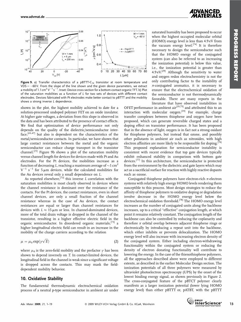
Figure 10. Ambient stability of FET devices. Transfer characteristics for polymer transistors witha) pBTCT; b) pBTTT and c), pATBT on prolonged exposure to air. d) Changes in normalized FETmobility calculated in saturation regime versus exposure time in air.
14
having the lowest ionization potential of the three polymerscontaining thienothiophene monomers.
The effect of thienothiophene polymer semiconductorexposure to ambient conditions over extended periods hasbeen observed in the absence of light. Figure 10 describes thechange in electrical characteristics of transistors fabricated withpBTCT, pBTTT, and pATBT semiconductors in a bottom-gate/bottom-contact configuration, in which the active semiconduc-tor layer is the exposed top surface. Confirmation of significantoxidative doping in both the pBTTTand pATBT transistor deviceover continued ambient exposure time can be observed inFigure 10b and c as a rise in the transistor off-current, and ashift to more positive turn on voltage, due to an increase inacceptor states in the bandtail. The pBTCT polymer seriesshowed the least evidence of oxidative doping, with only smallchanges in both OFF current and turn on voltage over almosttwo months exposure to air. Mobility values of both pBTCT andpATBT remained above 60% of their initial values for over20 days, as shown in the comparative graph in Figure 10d. Thedifference in stability between pBTCTand pBTTT can clearly beattributed to the lower lying HOMO energy of pBTCT. However,the contrast between pBTTT and pATBT is remarkableconsidering the small difference in measured ionizationpotential.
Nevertheless, in filtered, low-humidity air, all transistor devicesincluding pBTTT remained relatively stable over an extendedperiod in the absence of light. Previous reports[30] have shownthat the transfer characteristics of a pBTTTdevice recorded over aperiod of over 70 days show only a minor change in Off currentand threshold voltage with a small decrease in On current. This
� 2009 WILEY-VCH Verlag GmbH & Co. KGaA, Weinheim
corresponds to a drop in mobility over themeasurement time-span by about a factorof three. Good stability has also beenreported for repeated electrical stressingof pBTTT devices in ambient air over50 h.[79] No special precautions were takento exclude moisture in this case. Thesereported discrepancies suggests that theimprovement in stability reported inlow-humidity air may in fact be due tothe unintentional removal of high elec-tron affinity impurities such as ozoneduring the dehumidification process.The levels of such pollutants are likelyto vary substantially from laboratory tolaboratory, which is certainly experimen-tally observed.
11. Synthesis ofThienothiophene Polymers
11.1. Thienothiophene Monomer
Preparation
Several routes have been developed tothieno[2,3-b]thiophene.[80–82] For exam-ple, Otsubu and co-workers reported an
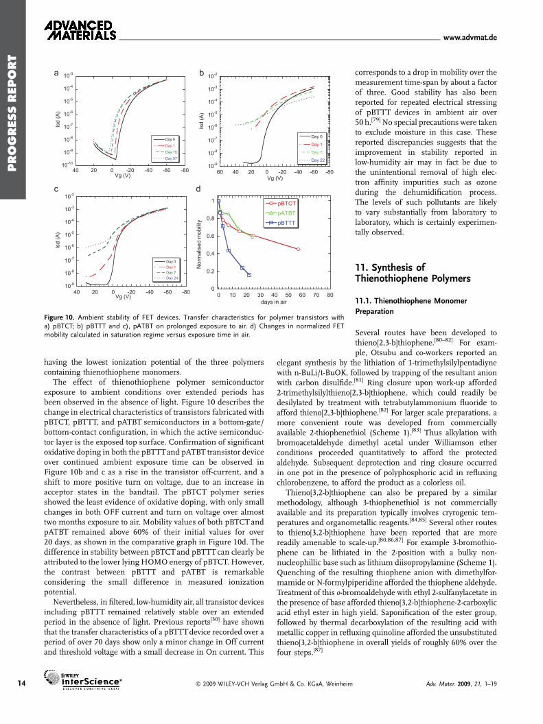
elegant synthesis by the lithiation of 1-trimethylsilylpentadiynewith n-BuLi/t-BuOK, followed by trapping of the resultant anionwith carbon disulfide.[81] Ring closure upon work-up afforded2-trimethylsilylthieno[2,3-b]thiophene, which could readily bedesilylated by treatment with tetrabutylammonium fluoride toafford thieno[2,3-b]thiophene.[82] For larger scale preparations, amore convenient route was developed from commerciallyavailable 2-thiophenethiol (Scheme 1).[83] Thus alkylation withbromoacetaldehyde dimethyl acetal under Williamson etherconditions proceeded quantitatively to afford the protectedaldehyde. Subsequent deprotection and ring closure occurredin one pot in the presence of polyphosphoric acid in refluxingchlorobenzene, to afford the product as a colorless oil.
Thieno[3,2-b]thiophene can also be prepared by a similarmethodology, although 3-thiophenethiol is not commerciallyavailable and its preparation typically involves cryrogenic tem-peratures and organometallic reagents.[84,85] Several other routesto thieno[3,2-b]thiophene have been reported that are morereadily amenable to scale-up.[80,86,87] For example 3-bromothio-phene can be lithiated in the 2-position with a bulky non-nucleophillic base such as lithium diisopropylamine (Scheme 1).Quenching of the resulting thiophene anion with dimethylfor-mamide or N-formylpiperidine afforded the thiophene aldehyde.Treatment of this o-bromoaldehyde with ethyl 2-sulfanylacetate inthe presence of base afforded thieno[3,2-b]thiophene-2-carboxylicacid ethyl ester in high yield. Saponification of the ester group,followed by thermal decarboxylation of the resulting acid withmetallic copper in refluxing quinoline afforded the unsubstitutedthieno[3,2-b]thiophene in overall yields of roughly 60% over thefour steps.[87]
Adv. Mater. 2009, 21, 1–19
PROGRESS
REPORT
www.advmat.de
Scheme 1. Synthesis of thieno[2,3-b]thiophene and thieno[3,2-b]thiophene.
The synthesis of 3,6-dialkylthieno[3,2-b]thiophene has beenreported by two alternate routes. Matzger and co-workersreported an elegant route starting from 3,4-dibromothiophene.[56]
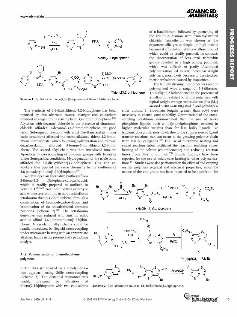
Acylation with decanoyl chloride in the presence of aluminumchloride afforded 2-decanoyl-3,4-dibromothiophene in goodyield. Subsequent reaction with ethyl 2-sulfanylacetate underbasic conditions afforded the mono-alkylated thieno[3,2-b]thio-phene intermediate, which following hydrolyzation and thermaldecarboxylation afforded 3-bromo-6-nonylthieno[3,2-b]thio-phene. The second alkyl chain was then introduced into the3-position by cross-coupling of bromine groups with 1-nonyneunder Sonogashira conditions. Hydrogenation of the triple bondafforded the 3,6-dialkylthieno[3,2-b]thiophene. Ong and co-workers later applied the same chemistry to the synthesis of3,6-pentadecylthieno[3,2-b]thiophene.[69]
Scheme 2. Two alternative route to 3,6-dialkylthieno[3,2-b]thiophene.
We developed an alternative synthesis from2-thieno[3,2- b]thiophene-carboxylic acid,which is readily prepared as outlined inScheme 1.[67,68] Treatment of this carboxylicacid with excess bromine in acetic acid affordstetrabromo thieno[3,2-b]thiophene, through acombination of bromo-decarboxylation andbromination of the unsubstituted aromaticpositions (Scheme 2).[88] The tetrabromoderivative was reduced with zinc in aceticacid to afford 3,6-dibromothieno[3,2-b]thio-phene. A variety of alkyl chains could bereadily introduced by Negishi cross-couplingunder microwave heating with an appropriatealkylzinc halide in the presence of a palladiumcatalyst.
11.2. Polymerization of thienothiophene
polymers.
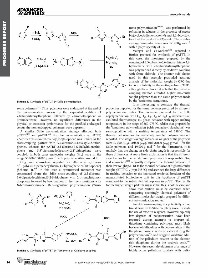
pBTCT was synthesized by a copolymeriza-tion approach using Stille cross-coupling(Scheme 3). The distannyl monomer wasreadily prepared by lithiation ofthieno[2,3-b]thiophene with two equivalents
Adv. Mater. 2009, 21, 1–19 � 2009 WILEY-VCH Verlag GmbH & Co. KGaA, Weinhe
of n-butyllithium, followed by quenching ofthe resulting dianion with trimethylstannylchloride. Trimethyltin was chosen as theorganometallic group despite its high toxicitybecause it afforded a highly crystalline productwhich could be readily purified. In contrast,the incorporation of less toxic tributyltingroups resulted in a high boiling point oil,which was difficult to purify. Attemptedpolymerization led to low molecular weightpolymers, most likely because of the stoichio-metric imbalance caused by impurities.
The trimethylstannyl monomer was readilypolymerized with a range of 5,5-dibromo-4,4-dialkyl-2,2-bithiophenes in the presence ofa palladium catalyst to afford polymers withtypical weight average molecular weights (Mw)around 50 000–60 000 g mol�1 and polydisper-
sities around 2. Side-chain lengths greater than octyl werenecessary to ensure good solubility. Optimization of the cross-coupling conditions demonstrated that the use of bulkyphosphine ligands such as tri(o-tolyl)phosphine, resulted inhigher molecular weights than for less bulky ligands liketriphenylphosphine, most likely due to the suppression of ligandtransfer reactions that can occur to the growing polymer chainfrom less bulky ligands.[89] The use of microwave heating andsealed reaction tubes facilitated the reaction, enabling super-heating of the solvent (chlorobenzene) and reducing reactiontimes from days to minutes.[90] Similar findings have beenreported for the use of microwave heating in other polymeriza-tions.[91] Studies were also performed on the effect of end-cappingon the polymers physical and electrical properties, since thenature of the end group has been reported to be significant for
im 15
PROGRESS
REPORT
www.advmat.de
Scheme 3. Synthesis of pBTCT by Stille polymerization.
16
some polymers.[92] Thus, polymers were endcapped at the end ofthe polymerization process by the sequential addition of2-tributylstannylthiophene followed by 2-bromothiophene orbromobenzene. However, no significant differences in thephysical or transistor performance for the purified endcappedversus the non-endcapped polymers were apparent.
A similar Stille polymerization strategy afforded bothpBTTT[30] and pATBT.[68] For the polymerization of pBTTT,2,5-trimethyl- (stannyl)thieno[3,2-b]thiophene was utilized as thecross-coupling partner with 5,5-dibromo-4,4-dialkyl-2,2-bithio-phenes, whereas for pATBT 2,5-dibromo-3,6-dialkylthienothio-phene and 5,50-bis(trimethyl)stannyl-2,20-bithiophene werecoupled. In both cases molecular weights (Mw) were in therange 50 000–100 000 g mol�1 with polydispersities around 2.
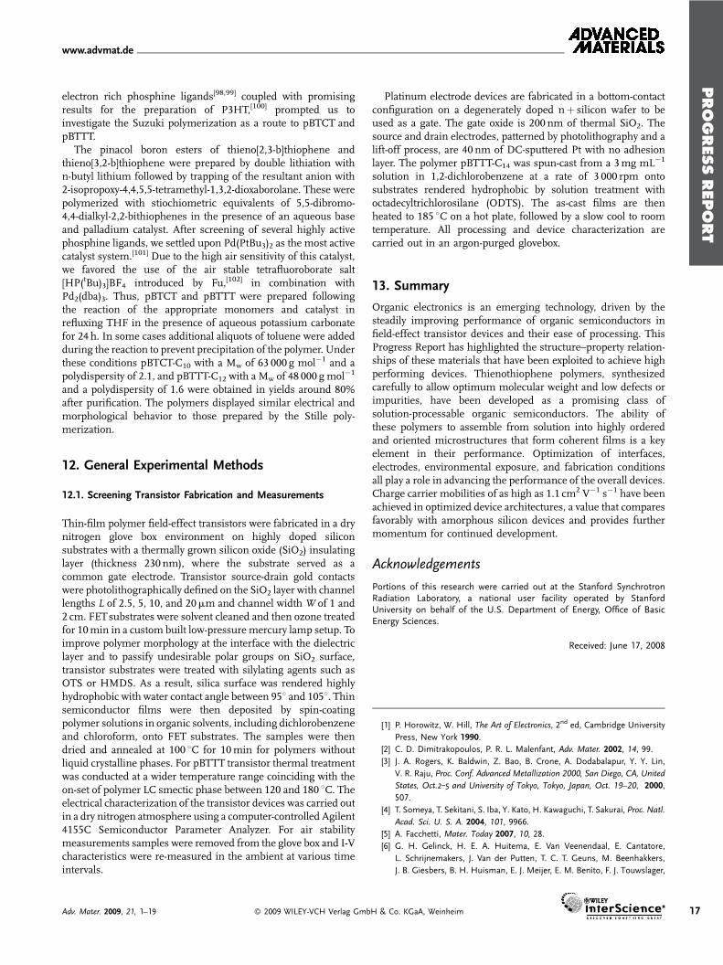
Ong and co-workers reported an alternative synthesisof poly(3,6-dipentadecylthieno[3,2-b]thiophene-co-bithiophene)(Scheme 4).[69] In this case a symmetrical monomer wasconstructed from the Stille cross-coupling of 2,5-dibromo-3,6-dipentadecylthieno[3,2-b]thiophene with 2-tri(butyl)stannyl-thiophene followed by bromination in the free a positions withN-bromosuccinimide. Dehalogenative polymerization (Yama-
Scheme 4. Synthesis of pATBT by Yamamoto or Oxidative coupling.
� 2009 WILEY-VCH Verlag GmbH & Co. KGaA, We
moto polymerization[93,94]) was performed byrefluxing in toluene in the presence of excessbis(cyclooctadiene)nickel (0) and 2,20-bipyridyl,to afford the product in 92% yield. The numberaverage molecular mass was 12 400 g mol�1
with a polydispersity of 1.6.Matzger and co-workers[95] reported a
further protocol for synthesis of pATBT. Inthis case, the monomer prepared by thecoupling of 2,5-dibromo-3,6-dinonylthieno[3,2-b]thiophene with 2-tri(butyl)stannylthiophenewas polymerized directly by oxidative couplingwith ferric chloride. The shorter side chainsused in this example precluded accurateanalysis of the molecular weight by GPC dueto poor solubility in the eluting solvent (THF),although the authors did note that the oxidativecoupling method afforded higher molecularweight polymer than the same polymer madeby the Yamamoto conditions.
It is interesting to compare the thermal
properties reported for the same polymer prepared by differentpolymerization routes. The polymers prepared by the Stillecopolymerization (with C12H25, C14H29 or C16H33 sidechains) allexhibited thermotropic LC phase behavior with upper meltingtemperature in the range of 260–275 8C, whilst that prepared bythe Yamamoto polymerization (with pentadecyl sidechains) wassemicrystalline with a melting temperature of 148 8C. Thethermal behavior for the oxidatively coupled polymer was notreported. The weight average molecular weights of the polymerswere 47 000 (C12), 60 000 (C14), and 98 000 (C16) g mol�1 for theStille polymers and 19 500 g mol�1 for the Yamamoto. It isunlikely that the change in side chain length is responsible forthese differences. A more likely explanation is that the differentaspect ratios for the two different polymers are responsible. Ongand co-workers[69] originally compared the thermal behavior oftheir low weight pATBT to the thermal behavior of highmolecularweight pBTTT-C14 (mpt 248 8C) and ascribed the large differencein melting behavior to the increased torsional freedom of theunsubstituted bithiophene unit in this backbone of pATBTcompared to the substituted bithiophene in pBTTT. The resultsfor the higher weight pATBTs suggest that this is not the case andshow that caution must be exercised whencomparing seemingly identical polymers ofdifferent molecular weight prepared by differ-ent polymerization routes.
Suzuki cross-coupling is a potentially attrac-tive alternative to Stille coupling since it avoidsthe use of toxic tin reagents. However, typicallylow degrees of polymerization have beenreported during attempts to prepare all-thiophene containing polymers, most likelybecause of difficulties with deboronation of thethiophene boronic acids or esters during thepolymerization[96] and sluggish oxidative addi-tion of the palladium catalyst to the electronrich thiophene during the catalytic cycle.[97]
However, the recent development of a range ofhighly active palladium catalysts with bulky,
inheim Adv. Mater. 2009, 21, 1–19
PROGRESS
REPORT
www.advmat.de
electron rich phosphine ligands[98,99] coupled with promisingresults for the preparation of P3HT,[100] prompted us toinvestigate the Suzuki polymerization as a route to pBTCT andpBTTT.
The pinacol boron esters of thieno[2,3-b]thiophene andthieno[3,2-b]thiophene were prepared by double lithiation withn-butyl lithium followed by trapping of the resultant anion with2-isopropoxy-4,4,5,5-tetramethyl-1,3,2-dioxaborolane. These werepolymerized with stiochiometric equivalents of 5,5-dibromo-4,4-dialkyl-2,2-bithiophenes in the presence of an aqueous baseand palladium catalyst. After screening of several highly activephosphine ligands, we settled upon Pd(PtBu3)2 as the most activecatalyst system.[101] Due to the high air sensitivity of this catalyst,we favored the use of the air stable tetrafluoroborate salt[HP(tBu)3]BF4 introduced by Fu,[102] in combination withPd2(dba)3. Thus, pBTCT and pBTTT were prepared followingthe reaction of the appropriate monomers and catalyst inrefluxing THF in the presence of aqueous potassium carbonatefor 24 h. In some cases additional aliquots of toluene were addedduring the reaction to prevent precipitation of the polymer. Underthese conditions pBTCT-C10 with a Mw of 63 000 g mol�1 and apolydispersity of 2.1, and pBTTT-C12 with a Mw of 48 000 g mol�1
and a polydispersity of 1.6 were obtained in yields around 80%after purification. The polymers displayed similar electrical andmorphological behavior to those prepared by the Stille poly-merization.
12. General Experimental Methods
12.1. Screening Transistor Fabrication and Measurements
Thin-film polymer field-effect transistors were fabricated in a drynitrogen glove box environment on highly doped siliconsubstrates with a thermally grown silicon oxide (SiO2) insulatinglayer (thickness 230 nm), where the substrate served as acommon gate electrode. Transistor source-drain gold contactswere photolithographically defined on the SiO2 layer with channellengths L of 2.5, 5, 10, and 20mm and channel width W of 1 and2 cm. FETsubstrates were solvent cleaned and then ozone treatedfor 10min in a custom built low-pressure mercury lamp setup. Toimprove polymer morphology at the interface with the dielectriclayer and to passify undesirable polar groups on SiO2 surface,transistor substrates were treated with silylating agents such asOTS or HMDS. As a result, silica surface was rendered highlyhydrophobic with water contact angle between 958 and 1058. Thinsemiconductor films were then deposited by spin-coatingpolymer solutions in organic solvents, including dichlorobenzeneand chloroform, onto FET substrates. The samples were thendried and annealed at 100 8C for 10min for polymers withoutliquid crystalline phases. For pBTTT transistor thermal treatmentwas conducted at a wider temperature range coinciding with theon-set of polymer LC smectic phase between 120 and 180 8C. Theelectrical characterization of the transistor devices was carried outin a dry nitrogen atmosphere using a computer-controlled Agilent4155C Semiconductor Parameter Analyzer. For air stabilitymeasurements samples were removed from the glove box and I-Vcharacteristics were re-measured in the ambient at various timeintervals.
Adv. Mater. 2009, 21, 1–19 � 2009 WILEY-VCH Verlag Gmb
Platinum electrode devices are fabricated in a bottom-contactconfiguration on a degenerately doped nþ silicon wafer to beused as a gate. The gate oxide is 200 nm of thermal SiO2. Thesource and drain electrodes, patterned by photolithography and alift-off process, are 40 nm of DC-sputtered Pt with no adhesionlayer. The polymer pBTTT-C14 was spun-cast from a 3mg mL�1
solution in 1,2-dichlorobenzene at a rate of 3 000 rpm ontosubstrates rendered hydrophobic by solution treatment withoctadecyltrichlorosilane (ODTS). The as-cast films are thenheated to 185 8C on a hot plate, followed by a slow cool to roomtemperature. All processing and device characterization arecarried out in an argon-purged glovebox.
13. Summary
Organic electronics is an emerging technology, driven by thesteadily improving performance of organic semiconductors infield-effect transistor devices and their ease of processing. ThisProgress Report has highlighted the structure–property relation-ships of these materials that have been exploited to achieve highperforming devices. Thienothiophene polymers, synthesizedcarefully to allow optimum molecular weight and low defects orimpurities, have been developed as a promising class ofsolution-processable organic semiconductors. The ability ofthese polymers to assemble from solution into highly orderedand oriented microstructures that form coherent films is a keyelement in their performance. Optimization of interfaces,electrodes, environmental exposure, and fabrication conditionsall play a role in advancing the performance of the overall devices.Charge carrier mobilities of as high as 1.1 cm2 V�1 s�1 have beenachieved in optimized device architectures, a value that comparesfavorably with amorphous silicon devices and provides furthermomentum for continued development.
Acknowledgements
Portions of this research were carried out at the Stanford SynchrotronRadiation Laboratory, a national user facility operated by StanfordUniversity on behalf of the U.S. Department of Energy, Office of BasicEnergy Sciences.
Received: June 17, 2008
[1] P. Horowitz, W. Hill, The Art of Electronics, 2nd ed, Cambridge University
Press, New York 1990.
[2] C. D. Dimitrakopoulos, P. R. L. Malenfant, Adv. Mater. 2002, 14, 99.
[3] J. A. Rogers, K. Baldwin, Z. Bao, B. Crone, A. Dodabalapur, Y. Y. Lin,
V. R. Raju, Proc. Conf. Advanced Metallization 2000, San Diego, CA, United
States, Oct.2–5 and University of Tokyo, Tokyo, Japan, Oct. 19–20, 2000,
507.
[4] T. Someya, T. Sekitani, S. Iba, Y. Kato, H. Kawaguchi, T. Sakurai, Proc. Natl.
Acad. Sci. U. S. A. 2004, 101, 9966.
[5] A. Facchetti, Mater. Today 2007, 10, 28.
[6] G. H. Gelinck, H. E. A. Huitema, E. Van Veenendaal, E. Cantatore,
L. Schrijnemakers, J. Van der Putten, T. C. T. Geuns, M. Beenhakkers,
J. B. Giesbers, B. H. Huisman, E. J. Meijer, E. M. Benito, F. J. Touwslager,
H & Co. KGaA, Weinheim 17
PROGRESS
REPORT
www.advmat.de
18
A. W. Marsman, B. J. E. Van Rens, D. M. De Leeuw, Nat. Mater. 2004, 3,
106.
[7] Y.-L. Loo, AIChE J. 2007, 53, 1066.
[8] H. Sirringhaus, Adv. Mater. 2005, 17, 2411.
[9] D. J. Gundlach, J. E. Royer, S. K. Park, S. Subramanian, O. D. Jurchescu,
B. H. Hamadani, A. J. Moad, R. J. Kline, L. C. Teague, O. Kirillov,
C. A. Richter, J. G. Kushmerick, L. J. Richter, S. R. Parkin, T. N. Jackson,
J. E. Anthony, Nat. Mater. 2008, 7, 216.
[10] M. L. Chabinyc, A. Salleo, Chem. Mater. 2004, 16, 4509.
[11] S. E. Burns, W. Reeves, B. H. Pui, K. Jacobs, S. Siddique, K. Reynolds,
M. Banach, D. Barclay, K. Chalmers, N. Cousins, P. Cain, L. Dassas,
M. Etchells, C. Hayton, S. Markham, A. Menon, P. Too, C. Ramsdale,
J. Herod, K. Saynor, J. Watts, T. von Werne, J. Mills, C. J. Curling,
H. Sirringhaus, K. Amundson, M. D. McCreary, Dig. Tech. Pap. —Soc.
Inf. Disp. Int. Symp. 2006, 37, 74.
[12] Y.-L. Loo, I. McCulloch, MRS Bulletin 2008, 33, 1.
[13] J. Veres, S. D. Ogier, S. W. Leeming, D. C. Cupertino, S. M. Khaffaf, Adv.
Funct. Mater. 2003, 13, 199.
[14] J. Veres, S. Ogier, G. Lloyd, D. de Leeuw, Chem. Mater. 2004, 16, 4543.
[15] L. Torsi, A. Dodabalapur, H. E. Katz, J. Appl. Phys. 1995, 78, 1088.
[16] Y. Xu, P. R. Berger, J. Appl. Phys. 2004, 95, 1497.
[17] L. Burgi, T. J. Richards, R. H. Friend, H. Sirringhaus, J. Appl. Phys. 2003, 94,
6129.
[18] R. Hamilton, C. Bailey, W. Duffy, M. Heeney, M. Shkunov, D. Sparrowe,
S. Tierney, I. McCulloch, R. J. Kline, D. M. DeLongchamp, M. Chabinyc,
Proc. SPIE—Int. Soc. Opt. Eng. 2006, 6336, 158.
[19] Z. Bao, A. Dodabalapur, A. J. Lovinger, Appl. Phys. Lett. 1996, 69,
4108.
[20] H. Sirringhaus, P. J. Brown, R. H. Friend, M. M. Nielsen, K. Bechgaard,
B. M. W. Langeveld-Voss, A. J. H. Spiering, R. A. J. Janssen, E. W. Meijer,
P. Herwig, D. M. de Leeuw, Nature 1999, 401, 685.
[21] B. H. Hamadani, D. J. Gundlach, I. McCulloch, M. Heeney, Appl. Phys.
Lett. 2007, 91, 243512.
[22] R. S. Loewe, P. C. Ewbank, J. Liu, L. Zhai, R. D. McCullough, Macromol-
ecules 2001, 34, 4324.
[23] I. A. Liversedge, S. J. Higgins, M. Giles, M. Heeney, I. McCulloch, Tett.
Lett. 2006, 47, 5143.
[24] M. S. A. Abdou, F. P. Orfino, Y. Son, S. Holdcroft, J. Am. Chem. Soc. 1997,
119, 4518.
[25] R. J. Kline, D. M. DeLongchamp, D. A. Fischer, E. K. Lin, L. J. Richter,
M. L. Chabinyc, M. F. Toney, M. Heeney, I. McCulloch, Macromolecules
2007, 40, 7960.
[26] M. Heeney, C. Bailey, K. Genevicius, M. Shkunov, D. Sparrowe, S. Tierney,
I. McCulloch, J. Am. Chem. Soc. 2005, 127, 1078.
[27] B. M. Medina, A. Van Vooren, P. Brocorens, J. Gierschner, M. Shkunov,
M. Heeney, I. McCulloch, R. Lazzaroni, J. Cornil, Chem. Mater. 2007, 19,
4949.
[28] P. Barta, F. Cacialli, R. Friend, M. Zagorska, J. Appl. Phys. 1998, 84, 6279.
[29] I. McCulloch, C. Bailey, M. Giles, M. Heeney, I. Love, M. Shkunov,
D. Sparrowe, S. Tierney, Chem. Mater. 2005, 17, 1381.
[30] I. McCulloch, M. Heeney, C. Bailey, K. Genevicius, I. MacDonald,
M. Shkunov, D. Sparrowe, S. Tierney, R.Wagner, W. Zhang,M. L. Chabinyc,
R. J. Kline, M. D. McGehee, M. F. Toney, Nat. Mater. 2006, 5, 328.
[31] D. M. DeLongchamp, R. J. Kline, E. K. Lin, D. A. Fischer, L. J. Richter,
L. A. Lucas, M. Heeney, I. McCulloch, J. E. Northrup, Adv. Mater. 2007, 19,
833.
[32] M. L. Chabinyc, M. F. Toney, R. J. Kline, I. McCulloch, M. Heeney, J. Am.
Chem. Soc. 2007, 129, 3226.
[33] B. S. Ong, Y. Wu, P. Liu, S. Gardner, J. Am. Chem. Soc. 2004, 126, 3378.
[34] L. San Miguel, A. J. Matzger, Macromolecules 2007, 40, 9233.
[35] Z. Bao, A. J. Lovinger, Chem. Mater. 1999, 11, 2607.
[36] A. R. Murphy, J. Liu, C. Luscombe, D. Kavulak, J. M. J. Frechet, R. J. Kline,
M. D. McGehee, Chem. Mater. 2005, 17, 4892.
� 2009 WILEY-VCH Verlag G
[37] R. J. Kline, M. D. McGehee, E. N. Kadnikova, J. Liu, J. M. J. Frechet, Adv.
Mater. 2003, 15, 1519.
[38] R. J. Kline, M. D. McGehee, E. N. Kadnikova, J. Liu, J. M. J. Frechet,
M. F. Toney, Macromolecules 2005, 38, 3312.
[39] A. Zen, J. Pflaum, S. Hirschmann, W. Zhuang, F. Jaiser, U. Asawapirom,
J. P. Rabe, U. Scherf, D. Neher, Adv. Funct. Mater. 2004, 14, 757.
[40] R. Pokrop, J.-M. Verilhac, A. Gasior, I. Wielgus, M. Zagorska, J.-P. Travers,
A. Pron, J. Mater. Chem. 2006, 16, 3099.
[41] J.-M. Verilhac, R. Pokrop, G. LeBlevennec, I. Kulszewicz-Bajer, K. Buga,
M. Zagorska, S. Sadki, A. Pron, J. Phys. Chem. B 2006, 110, 13305.
[42] J.-F. Chang, J. Clark, N. Zhao, H. Sirringhaus, D. W. Breiby,
J. W. Andreasen, M. M. Nielsen, M. Giles, M. Heeney, I. McCulloch,
Phys. Rev. B 2006, 74, 115318.
[43] M. Brinkmann, P. Rannou, Adv. Funct. Mater. 2007, 17, 101.
[44] A. Salleo, M. L. Chabinyc, M. Yang, R. Street, Appl. Phys. Lett. 2002, 81,
4383.
[45] R. J. Kline, D. M. DeLongchamp, D. A. Fischer, E. K. Lin, M. Heeney,
I. McCulloch, M. F. Toney, Appl. Phys. Lett. 2007, 90, 062117.
[46] L. Chabinyc Michael, F. Toney Michael, R. J. Kline, I. McCulloch,
M. Heeney, J. Am. Chem. Soc. 2007, 129, 3226.
[47] M. L. Chabinyc, R. Lujan, F. Endicott, M. F. Toney, I. McCulloch,
M. Heeney, Appl. Phys. Lett. 2007, 90, 233508/1.
[48] T. J. Prosa, M. J. Wimokur, J. Moulton, P. Smith, A. J. Heeger, Macromol-
ecules 1992, 25, 4364.
[49] P. Brocorens, J. Cornil, M. L. Chabinyc, M. F. Toney, M. Shkunov,
M. Heeney, I. McCulloch, R. Lazzaroni, Adv. Mater. 2009,
DOI:10.1002/adma.200801668.
[50] J. Stohr, NEXAFS Spectroscopy, Springer Series in Surface Science Vol. 392,
Springer, Berlin 1992.
[51] a) J. E. Northrup, Phys. Rev. B: Condens. Matter Mater. Phys. 2007, 76,
245202/1. b) A. Salleo, personal communication.
[52] J. E. Anthony, Chem. Rev. 2006, 106, 5028.
[53] A. Zen, M. Saphiannikova, D. Neher, U. Asawapirom, U. Scherf, Chem.
Mater. 2005, 17, 781.
[54] A. Babel, S. A. Jenekhe, Synth. Met. 2005, 148, 169.
[55] Z. Bao, Y. Feng, A. Dodabalapur, V. R. Raju, A. J. Lovinger, Chem. Mater.
1997, 9, 1299.
[56] X. Zhang, M. Koehler, A. J. Matzger, Macromolecules 2004, 37, 6306.
[57] M. Turbiez, P. Frere, P. Leriche, N. Mercier, J. Roncali, Chem. Comm. 2005,
1161.
[58] N. Hergue, P. Frere, Org. Biomol. Chem. 2007, 5, 3442.
[59] E. Lim, B. J. Jung, J. Lee, H. K. Shim, J. I. Lee, Y. S. Yang, L. M. Do,
Macromolecules 2005, 38, 4531.
[60] E. Lim, B. J. Jung, H. K. Shim, Macromolecules 2003, 36, 4288.
[61] W. H. Tang, L. Ke, L. W. Tan, T. T. Lin, T. Kietzke, Z. K. Chen, Macro-
molecules 2007, 40, 6164.
[62] M. C. Gather, M. Heeney, W. Zhang, K. S. Whitehead, D. C. C. Bradley,
I. McCulloch, A. J. Campbell, Chem. Commun. 2008, 1079.
[63] E. Lim, Y. M. Kim, J. I. Lee, B. J. Jung, N. S. Cho, J. Lee, L. M. Do,
H. K. Shim, J. Pol. Sci. A. Poly. Chem. 2006, 44, 4709.
[64] H. Sirringhaus, R. J. Wilson, R. H. Friend, M. Inbasekaran, W. Wu,
E. P. Woo, M. Grell, D. D. C. Bradley, Appl. Phys. Lett. 2000, 77, 406.
[65] Y. M. Kim, E. Lim, I.-N. Kang, B.-J. Jung, J. Lee, B. W. Koo, L.-M. Do,
H.-K. Shim, Macromolecules 2006, 39, 4081.
[66] S. Tierney, C. Bailey, W. Duffy, R. Hamilton, M. Heeney, I. MacDonald,
M. Shkunov, D. Sparrowe, W. Zhang, I. McCulloch, PMSE Preprints 2007,
96, 180.
[67] M. Heeney, R. Wagner, I. McCulloch, S. Tierney, WO2005111045,
2005.
[68] M. Heeney, C. Bailey, W. Duffy, M. Shkunov, D. Sparrowe, S. Tierney,
W. Zhang, I. McCulloch, PMSE Preprints 2006, 95, 101.
[69] Y. N. Li, Y. L. Wu, P. Liu, M. Birau, H. L. Pan, B. S. Ong, Adv. Mater. 2006,
18, 3029.
mbH & Co. KGaA, Weinheim Adv. Mater. 2009, 21, 1–19
PROGRESS
REPORT
www.advmat.de
[70] J. E. Northrup, M. L. Chabinyc, R. Hamilton, I. McCulloch, M. Heeney,
J. Appl. Phys. 2008, 104.
[71] M. Heeney, C. Bailey, S. Tierney, I. McCulloch, WO2006021277, 2006.
[72] B. H. Hamadani, C. A. Richter, D. J. Gundlach, R. J. Kline, I. McCulloch, M.
Heeney, J. Appl. Phys. 2007, 102, 044503/1.
[73] T. Kreouzis, D. Poplavskyy, S. M. Tuladhar, M. Campoy-Quiles, J. Nelson,
A. J. Campbell, D. D. C. Bradley, Phys. Rev. B: Condens. Matter Mater. Phys.
2006, 73, 235201/1.
[74] D. M. de Leeuw, M. M. J. Simenon, A. R. Brown, R. E. F. Einerhand, Synth.
Met. 1997, 87, 53.
[75] E. J. Meijer, C. Detcheverry, P. J. Baesjou, E. van Veenendaal, D. M. de
Leeuw, T. M. Klapwijk, J. Appl. Phys. 2003, 93, 4831.
[76] M. Chabinyc, R. A. Street, J. E. Northrup, Appl. Phys. Lett., 2007, 90,
123508.
[77] H. Rost, J. Ficker, J. S. Alonso, L. Leenders, I. McCulloch, Synth. Met. 2004,
145, 83.
[78] M. H. Yoon, S. A. DiBenedetto, A. Facchetti, T. J. Marks, J. Am. Chem. Soc.
2005, 127, 1348.
[79] T. Umeda, S. Tokito, D. Kumaki, J. Appl. Phys. 2007, 101, 054517.
[80] W. J. Archer, R. Taylor, J. Chem. Soc. Perkin Trans. 2 1982, 295.
[81] T. Otsubo, Y. Kono, N. Hozo, H. Miyamoto, Y. Aso, F. Ogura, T. Tanaka,
M. Sawada, Bull. Chem. Soc. Jpn. 1993, 66, 2033.
[82] S. Yasuike, J. Kurita, T. Tsuchiya, Heterocycles 1997, 45, 1891.
[83] M. Heeney, C. Bailey, K. Genevicius, M. Giles, M. Shkunov, D. Sparrowe,
S. Tierney, W. Zhang, I. McCulloch, Proc. SPIE-Int. Soc. Opt. Eng. FIELD
2005, 5940, 594007/1.
[84] B. L. Chenard, R. L. Harlow, A. L. Johnson, S. A. Vladuchick, J. Am. Chem.
Soc. 1985, 107, 3871.
[85] R. Cagnoli, M. Lanzi, A. Mucci, F. Parenti, L. Schenetti, Synthesis 2005, 267.
Adv. Mater. 2009, 21, 1–19 � 2009 WILEY-VCH Verlag Gmb
[86] P. Leriche, J. M. Raimundo, M. Turbiez, V. Monroche, M. Allain,
F. X. Sauvage, J. Roncali, P. Frere, P. J. Skabara, J. Mater. Chem. 2003,
13, 1324.
[87] D. W. Hawkins, B. Iddon, D. S. Longthorne, P. J. Rosyk, J. Chem. Soc.
Perkin Trans. 1 1994, 2735.
[88] L. S. Fuller, B. Iddon, K. A. Smith, J. Chem. Soc. 1997, 3465.
[89] F. E. Goodson, T. I. Wallow, B. M. Novak, Macromolecules 1998, 31,
2047.
[90] S. Tierney, M. Heeney, I. McCulloch, Synth. Met. 2005, 148, 195.
[91] F. Galbrecht, T. W. Bunnagel, U. Scherf, T. Farrell,Macromol. Rapid Comm.
2007, 28, 387.
[92] Y. Kim, S. Cook, J. Kirkpatrick, J. Nelson, J. R. Durrant, D. D. C. Bradley,
M. Giles, M. Heeney, R. Hamilton, I. McCulloch, J. Phys. Chem. C 2007,
111, 8137.
[93] T. Yamamoto, J. Organomet. Chem. 2002, 653, 195.
[94] T. Yamamoto, A. Morita, Y. Miyazaki, T. Maruyama, H. Wakayama,
Z. Zhou, Y. Nakamura, T. Kanbara, S. Sasaki, K. Kubota, Macromolecules
1992, 25, 1214.
[95] L. S. Miguel, A. J. Matzger, Macromolecules 2007, 40, 9233.
[96] M. Jayakannan, J. L. J. van Dongen, R. A. J. Janssen,Macromolecules 2001,
34, 5386.
[97] S. Guillerez, G. Bidan, Synth. Met. 1998, 93, 123.
[98] F. Bellina, A. Carpita, R. Rossi, Synthesis, 2004, 15, 2419.
[99] S. Kotha, A. K. Ghosh, Synlett. 2002, 451.
[100] I. A. Liversedge, S. J. Higgins, M. Giles, M. Heeney, I. McCulloch, Tett.
Lett. 2006, 47, 5143.
[101] S. Tierney, M. Heeney, W. Zhang, S. Higgins, I. Liversedge, EP 1754736,
2007.
[102] M. R. Netherton, G. C. Fu, Org. Lett., 2001, 3, 4295.
H & Co. KGaA, Weinheim 19