Embed Size (px)
Citation preview

NASW-4435
SEMM 1
VPI/NASA Senior Design Project 1990-91
SOLAR-ELECTRIC-PROPULSION
CARGO VEHICLES FOR SPLIT/SPRINTMARS MISSION
/A/-/_ _,: ?g
Advisors:
Professor Anthony Jakubowski
Aerospace Engineering Department
Virginia Polyechnic Institute
Davy A. Haynes
Space Exploration Initiative Office
NASA Langley Research Center
Student Members:
Christopher E. Callaghan
Michael D. Crowe
Matthew J. Swis
Scott Thoden
Marcus R. Mickney
C. Keith Montgomery
Robert Waiters
June 1991
Department of Aerospace and Ocean Engineering
Virginia Polytechnic Institute and State University
Blacksburg, Virginia 24061
(NASA-CR-I_qgR3) SOLAR-ELECIREC-PROPULSICN
CAR_ Vr_TCLLS FOR SPLIT/SPR[NT HARS _ISSTON
(Vir_jinia Polytechnic Inst. and State Univ.)_ 0 CSCL 22B
G3/l_
N92-2 ]526
https://ntrs.nasa.gov/search.jsp?R=19920014283 2018-07-04T00:07:11+00:00Z


Table of Contents
List of Figures
List of Tables
Abstract
1. Introduction
1.1 Team Organization
1.2 Background
1.3 Design Requirements1.4 Mission Scenario
1.5 Vehicle Configuration
2. Trajectory Analysis
2.1 Mission Requirements2.2 Trajectory Calculations
3. Propulsion Systems
3.1 Trade-Off Analysis3.2 Thrusters
3.3 Tanks
4. Power Generation
4.1 Solar Cells
4.2 Wiring
4.3 Power Management and Distribution
5. Vehicle Structures
5.1 Structure Evolution5.2 Materials Selection
5.3 Truss Calculations
5.4 Radiation Shielding
6. GNC & Communications Systems
6.1 Telecommunications
6.2 Guidance, Navigation & Control
Page i
Page ii
Page iii
Page 1
Page 8
Page 17
Page 31
Page 47
Page 53


7. Vehicle Launch and Assembly Scenario Page 62
7.1 Launch Packaging7.2 Assembly7.3 Docking7.4 Maintenance
8. Design Configuration Summary Page 68
APPENDICES
A. TRUSS ELEMENT CALCULATIONS
REFERENCES

LIST OF FIGURES
Figure 2-1
Figure 2-2
Figure 2-3
Figure 2-4
Figure 2-5
Figure 2-6
Figure 2-7
Figure 2-8
Figure 3-1
Figure 3-2
Figure 3-3
Figure 3-4
Figure 3-5
Figure 3-6
Figure 3-7
Figure 3-8
Figure 3-9
Figure 4-1
Figure 4-2
Figure 4-3
Figure 4-4
Figure 4-5
Figure 4-6
Figure 4-7
Figure 5-1
Figure 5-2
Figure 5-3
Figure 5-4
Figure 6-1
Figure 6-2
Figure 6-3
Figure 6-4
Figure 7-1
Figure 7-2
Figure A-1
Figure A-2
Optimum Power vs. Isp
Optimum Power vs. Trip Time to Mars
Fuel Use vs. Trip Time to Mars
Return Voyage Fuel Use vs. Time
Thruster Burn Time vs. Isp
Thrust Time vs. Trip Time to Mars
Mission Time of Flight vs. Isp
Trajectory
Schematic of Ion Engine
Mass vs. Isp
Payload Ratio vs. Isp
Thruster Efficiency vs. Isp
Thrust vs. Isp
Elliptical Fuel Tank
Collapsible Bladder Tank
Thruster Fuel Tank Interface
Argon Thruster Configuration
Efficiency vs. Backup
Photon Absorption
Overall Configuration
Panel Module
Solar Array Wiring Scheme
Solar Cell Wiring Scheme
Power System Configuration
Possible Configurations
Cargo Bay Cross Section
Box Bays
Shielding
Communication Linkages
Command Subsystem
Telemetry Subsystem
Sun Sensors
Launch Packaging
Section Assembly
Truss Forces
Truss Half Element
Page 9
10
10
11
12
12
13
16
17
19
19
20
21
23
24
25
29
32
32
38
39
42
43
46
47
48
51
52
56
57
57
59
63
65
70
73


ii
Table 1-1
Table 2-1
Table 3-1
Table 3-2
Table 3-3
Table 3-4
Table 3-5
Table 3-6
Table 3-7
Table 5-1
Table 5-2
Tab le 6-1
Table 6-2
Table 6-3
Table 8-1
Table 8-2
LIST OF TABLES
SEMM1 Design Summary
Mission Time
Argon Thrusters
Storage Comparison
Argon Storage
Mass Breakdown
Thruster Utilization Scheme
Thruster C_aaracterist ics
Propulsion System Mass Summary
Composite Materials Comparison
Power System Mass Summary
Data Link Summary
Mass and Power Summary
Gyro Data
Spacecraft Mass Summary
Spacecraft Specifications Summary
Page 7
14
18
22
24
26
27
28
30
49
51
55
55
60
68
69


.o.
111
ABSTRACt
In support of the proposed exploration of Mars, an unmanned cargo ferry SEMM1
(Solar Electric Mars Mission) has been designed. The vehicle is based on solar
electric propulsion, and required to transport a cargo of 61,000 kilograms. The
trajectory is a combination of spirals; first, out from LEO, then around the sun, then
spiral down to low Mars orbit. The spacecraft produces 3.03 MWe power using
photovoltaic flexible blanket arrays. Ion thrusters using argon as a propellant have
been selected to drive the ship, providing about 60 Newtons of thrust in low Earthorbit. The configuration is based on two long truss beams to which the 24individual, self-deployable, solar arrays are attached. The main body module
supports the two beams and houses the computers, electrical, and control
equipment. The thruster module is attached to the rear of the main body, and thecargo to the front.


1. INTRODUCTION
1.1 SEMM1 Team
Team Leader
Trajectory
Propulsions
Power System
Structures
Christopher Callaghan
Marcus Mickney
Keith Montgomery
Michael Crowe
Matthew Swis
Scott Thoden
Robert Walters
Robert Waiters
Christopher CallaghanMatthew Swis
Communications - Marcus Mickney


2
1.2 Background
1.2a Historical Background
In May of 1990, President Bush visited Marshall Space Flight Center in Houston,
Texas and made a historical speech. His words there crystallized the goals of many
Americans: to land again on the Moon and establish a permanent presence there,then to send a manned mission to Mars. The President also set a date of 2019 for
this momentous first landing on Mars, and NASA engineers and science fans
nationwide raced back to their drawing boards. A Mars mission had long been
• dreamed about, but never studied in depth. A call was put out for papers and ideas
that might aid in the accomplishment of the long awaited journey.
Every senior engineering class at Virginia Tech participates in a design project in
their major field of study. This year one of the topics available to the Aerospace
and Ocean Engineering class was the development of a conceptual design for a
spacecraft that would operate in support of the Mars mission. Specifically, the
design would be for an unmanned cargo ferry that could bring equipment andsupplies to Mars.
1.2b Definition of Concept
The concept for a Mars cargo ferry stems from the idea of a progressive presence
in deep space in support of human exploration. This idea includes the short term
use of present technology to begin exploration and mapping of the Martian surface.
Much work must be done before any men ever step onto the surface of another
planet, including terrain mapping, atmospheric and soil sampling, and the
establishment of a communication system on and around Mars.
Once newer technology has reached maturity, it would be used immediately to pushthe exploration ahead. Automated workers would assemble scientific bases and
habitats for the humans soon to come. Orbiting satellites would be placed aroundthe planet to provide constant communication and commands to the machines and
probes on Mars. The cargo ferry will be used to bring these materials to Mars. Itis required to drop the cargo module off in orbit around Mars, to be transferred
down to the surface by an orbital transfer vehicle, either manned or automated.
The cargo ferry is a vital workhorse in this overall plan.


3
1.3 Design Considerations
A design of a major space vehicle must always identify several key criteria dependent
on the mission. The cargo ferry will be built with these factors in mind: mission
accomplishment, proven technology, and reusability.
The main mission of the ferry is to deliver a cargo to Mars orbit. Although there
will be no humans on board the ship, its cargo will be million dollar machinery,
probes, and equipment. The loss of this cargo will not be easily replaceable, sincemost of it will be uniquely designed for this mission. The inability to perform themission will push the calendar for Mars expansion back several years. Therefore,
the craft must survive and reach its destination, and all design characteristics reflectthis consideration.
To make the mission more realizable, the SEMM1 technology level will include
mostly current production hardware. A cargo vessel is not a testing bed for exciting,
innovative gadgetry. However, space technology is evolving at a rapid rate, and
technological advances and trends should not be overlooked. Everything used on
the ferry has been studied for several years by top NASA and industry engineers.
By the time the ship is launched, most of the components will have been flown in
space and probably improved over what is presented in this report. Performance in
certain areas was projected based on what researchers predicted would be available.
The third consideration was endurance. The ship must be dependable and reusable,or the cost of its operation would overshadow its usefulness.,as a means of
transporting cargo. Degradation was analyzed, and modularity of the componentswas emphasized so that easy maintenance could be performed by robots orastronauts in Earth's orbit.


4
1.4 Mission Scenario - General Assumptions
The construction of a cargo ferry has its place in a long list of space-related events.First and foremost is the development of a heavy lift launch vehicle (HLV) to boost
the pieces of SEMM1 into Low Earth Orbit (LEO). The space shuttle is aremarkable machine and is capable of great scientific experiments, but it is not big
enough or strong enough to be used for launching the cargo. A more powerful,
unmanned version of the shuttle, called Shuttle-C, has been proposed and would fitthe requirements for a launch vehicle. "Big, dumb boosters" are also a candidate fora comeback, having been phased out in the 1970's with the last of the Atlaslaunches.
The second most important milestone is the construction and operation of a large,
manned, orbiting station. This station could be used for science and astronomical
study, but is most important to this mission as a construction site. Current proposals
for Space Station Freedom do not include such capabilities in Phase I, to becompleted in 1995. Phase II, however, will include the addition of special
construction bays where lunar and interplanetary vehicles may be assembled and
launched. Space construction offers the opportunity for huge structures to be built
that would not have been able to w.;thstand the force of launching.
Other assumptions include the expansion of a Deep Space Network (DSN) forinterplanetary communications. This will require the placement of relay satellites
in Mars orbit before the cargo mission takes place. Also assumed is that Congress
and the American people will continue to support progress in space, for without
proper funding, the technology referenced in this paper may not exist.


5
1.5 Vehicle Configuration
1.Sa Design Requirements
The initial requirements for SEMM1 were laid down before any research began.
The cargo ferry will be capable of carrying a 61,000 kg module. This cargo will besized according to the Shuttle-C cargo bay.
SEMM1 will be solar powered. The power collected will be used to power ion
thrusters using argon as a propellant. The nature of electric propulsion makes thecraft incapable of great accelerations and therefore very slow, which makes sense
considering the purpose of the vehicle. The total trip time to Mars and back was
suggested at around three years, since the cargo does not have to be on Mars
immediately, but timely enough to keep up the pace of the exploration.
1.Sb Design Evolution
The layout of the vehicle was the first step to be considered. Pictures of Solar
Electric Propulsion (SEP) vehicle designs taken from other sources showed a variety
of configurations. Common sense dictated that most of the system's hardware
components (i.e. cargo, computers, power conversion system, communications and
navigational gear) should be housed together in a module or two. Most of the
configuration choices differed only in shape of the solar arrays and location of theengines.
The first concept that was considered was building the solar array as one immense
flat sheet. The core module containing the cargo and ship hardware would be
suspended in the center, with the ion thrusters mounted on wingtips that extended
out from each corner. This design gave the thrusters clearance from the arrays and
a very large moment arm that would help with maneuvers. However, it requiredpumping fuel from the central tanks to each wing pod, a massive support structure
for the solar panels, and considerable construction and assembly in space.
Current satellites, including the Hubble Space Telescope, use a two-wing approach.
The main body supports two wings of solar panels opposite each other. This givesthe arrays the ability to rotate independently of the ship, and the ion thrusters could
be mounted together in a single module directly behind the core body. This designwas chosen early on as the most likely candidate for configuration.
Solar arrays can use various collection strategies to gather sunlight that falls onthem. Research quickly showed that optical concentrators would be ideal;
lightweight, efficient, and operating at a high temperature. However, difficultieswith assembly of a support structure and very strict pointing tolerances eliminated
the concentrators as an option and preassembled, self-deployable flat panel arrays
were chosen due to their maturity, relative ease of control and less stringent rigidity
requirements. In particular, the ability to be deployed automatically was a benefitwhen considering assembly times and complexity.


The configuration of SEMM1 uses a square-bay truss beam to anchor 24 self-
deployable flexible blanket solar arrays. These arrays provide a total area of 10,057
square meters and produce 3.03 Mwe of power at average output. A multi-bandgap
cell using Indium Phosphide (InP) was chosen because of the strong radiationresistance it provided. In fact, the cell suffers almost no degradation when kept
above 100°C and is the key to the power system's reusability.
The above power is required to fire the ion thrusters located in the module on the
rear of the central body core. The size of the thrusters was determined using an
approximate optimization that balanced specific impulse, thrust, efficiency, and
power consumption. The optimal thrusters were found to be about 2 meters in
diameter, each capable of producing approximately 6 Newtons of thrust. Thethruster module contains 13 thrusters which can be fired in various combinations to
provide the thrust needed for the ship to complete various changes in orbit. The
optimal specific impulse was found to be 8,000 seconds.
Xenon has also been analyzed as a possible fuel for SEMM1. Although much more
expensive and volatile, xenon is denser than argon, so that the total fuel volume
required for the trip was almost three times smaller. Xenon operates more
efficiently, and was found to perform best when used with 1 meter diameter
thrusters capable of producing 3.2 N of thrust. The specific impulse in this case is
still 8,000 seconds and 29 thrusters are required to provide the same mission
flexibility and redundancy.
The total mass of the cargo ferry is estimated at 120,000 kg. Using trajectory
programs developed by the design team, a course for SEMM1 was charted that
would spiral the ship slowly out of Earth's gravitational field. The optimal thrust
was established at about 60 N at Earth. SEP is an economical way to go, but is very
slow, requiring several months just to escape the influence of Earth. The ship then
spirals around the sun and intercepts Mars. Once caught by the planet's gravity, the
cargo vessel then spirals down to Low Mars Orbit (LMO) where it completes itsmission.
The total trip time to Mars was found to be nearly two years. Cargo dropped off
at Mars and fuel used on the outbound trip will reduce the total vehicle mass so that
the return trip will only take one and one half years. Once in LEO, SEMM1 will
rendezvous with Space Station Freedom where it will be checked, refurbished, and
refueled for another trip.


7
1.5c Design Summary
The driving parameters in the design of SEMM1 are nearly all dependent on eachother. Solutions to the mission requirements could be found only by using an
iterative process of optimization that suggested a balance between weight, power,
and length of mission. The main design conclusions are summarized below.
Cargo Mass
Cargo 30 m long by 7 mVolume dia.
Array Area 10,368 ms
Array Power 3.06 Mwe
Isp (Argon) 8,000 seconds
Thruster 2 m dia.Size
Thrust 60 N
(LEO)
Trip to Mars 654 days
Return Trip 497 days
Initial Mass
61,000 kg
about 120,000 kg
TABLE 1-1 SEMM1 Design Summary


2. TRAJECTORY ANALYSIS
2.1 MISSION REQUIREMENTS
Our mission is to transport 61,000 kg of cargo from low Earth orbit at an altitudeof 400 Ion to low Mars orbit with an altitude of 500 km and inclination of 70
degrees. The ship is to be powered using solar energy and propelled by an electricpropulsion system. The craft is to make this journey three times, with repairs and
refueling done at an Earth-orbiting space station. For the trajectory analysis it wasconvenient to divide the mission into seven phases:
1) Escape from LEO/Plane change2) Heliocentric transfer to Mars
3) Mars capture spiral
4) Mars loiter/Cargo drop
5) Mars escape spiral
6) Heliocentric transfer to Earth
7) Dock with space station at Earth
Spiral transfers were employed because of the low thrust capability of electrical
thrusters. Since the cargo ferry is power limited, time was a crucial factor in our
analysis.


2.2 TRAJECTORY CALCULATIONS
Initial calculations were performed using a program _ which generated rough
estimates of trip times and fuel required. Later, the program QUICKTOP wasmade available, and all orbital calculations were revised.
To begin the optimization process, a goal of a maximum round trip mission time ofabout three years was established. This decision was made as a compromise
between shorter times (2-2.5 years) requiring higher fuel and power usage and verylong transfer times.
For a moderate range of specific impulse, and an initial mass of 140,000 kg, around-trip time of 3 yrs corresponded to an Earth-Mars transfer time of about 1.8
years. Using this time, and the values of initial estimates of vehicle mass and Isp,
power was first optimized using QUICKTOP's power optimization function. Figure
2-1 shows an "optimum" power of 3.04 MW for an Isp of 8000 sec.
3 6
3
3 4
_' 3 3
3a
:3.t
3
2.9
2,8
OPTIMUM POWE!q vs ISP
(ti'lD time -- _I'I Clays)
/
t t I t ! I ! 1 i i I i tl i i i i"_4 "P 8 B 2 B 8 9 9 4 .8 102 10 S
C Thousa nc_)
ISP C s_onc_ 3
FIGURE 2-1


10
When this value for "optimum" power was returned to QUICKTOP, the trip time
was verified (Figure 2-2). The next phase of optimization involved minimizing the
fuel required (Figure 2-3) for the Earth-Mars trajectory.
OPTIMUM POWER vs TRIP TIME TO MARS
CIsP - 8oo6)52
5
48
4.6
44
42
4
38
38
3.4
3.2
3
28
26
22
2 ' -i
400 500 600 _0 800
TRIP T_ME ((3ays)
FIGURE 2-2
12 4_
11 (1_
10 81
104_
10211
10 C_
FUEL USE vs TRIP TIME TO MARS
CISP . _O_
i
480 T;_O 560 600 640
TRIP TII,E COllyQ)
580 ?20
FIGURE 2-3


11
Since an actual minimum is not present on the plot of fuel vs trip time, an approach
considering diminishing returns was used for the return voyage. As figure 2-3indicates, after a rapid drop in fuel required with increasing trip time, the fuel
consumption with time starts to level off around 630 days. These plots were
generated using an effective power of 3MW (at Earth), and an Isp of 8000 sec.
i
15,5t
150_
14 5_11i
14,01
13 C_
12 51i
12 O_
11 51
11 Oe_
10 51
RETURN VOYAGE FUEL USE vs TIME
C I SP = 8000)
I I I z
300 400
i I I I 1 1 J "1 I iOI 1 9"'_ I I
420 4-40 460 480 500 520 540 560
TIME CdayS_
FIGURE 2-4
Once the time of flight and fuel use were obtained, thrust time was considered in
order to determine the effect of trip time upon required thruster redundancy. The
plot of thrust time vs trip time closely followed the fuel use plot, to which thrust
time is directly related. Thus, in minimizing fuel use, a secondary effect of reduced
thrust time allowed us to lower thruster redundancy.(see Figures 2-5 & 2-6)


12
14
13
12
11
10
9
8
7
THRUSTER BURN TIME vs I SR
(trip tl_ : 620 days)
I I I I I I I I I I i I I I I I 1 o;34 78 82 _18 9 9 4 98 10 2 6
C Tho,.,'sa*._,o,s )
ISP Cs*_: or,_,s)
FIGURE 2-5
8 8
THRUST TIME v£ TRIP TIME TO MA_qS
C ISP : BOO0)
).
_=,.3
8 7
86
e 4
83
B 2
81 I I I I I
480 520 560
I I I I--IlL I
600 640 680 720
TRiP Tlk_ CClayg)
FIGURE 2-6


13
Using the revised mass estimates, an overall mission time of flight vs Isp plot was
developed (Figure 2-7) for the 3MW power near Earth and an Isp of 8000 sec.Note that this curve is a function of many variables: with a constant initial mass, ahigher Isp usually involves a longer voyage; but it also requires less fuel, whichlowers initial mass and increases thrust acceleration. These varying factors result in
a minimum trip time occurring at an Isp of about 8000 sec.
-0-
118
117
1 16
1,15
I 14
113
1 12
I 11
I 1
I 09
I OB
MISSION TIMF OF FLIGHT vs ISP
(CLod, or = _ at Eort_)
I I 718 1 1 I I I I 1 I I I I 1012 1 I74 82 86 9 94 98 106
C Thouse nO, s )
_SP CSEC_
FIGURE 2-7
The 70 ° inclination change at Mars is accomplished during the Mars capture spiral.When the vehicle reaches an altitude of around 350,000 km, it reorients its thrust
direction perpendicular to its orbital plane. It takes about 31 days for the vehicleto move 70 ° in longitude. The thrust direction is then moved back into the orbital
plane and the vehicle continues to spiral down until it reaches 500 km altitude,
where it holds in a loiter orbit and deploys the cargo. A similar plane change
maneuver on the return trip will require 15 days of thrusting in the out-of-orbitplane direction.


14
2.2a LAUNCH DATE OPTIMIZATION
In order to optimize fuel use and trip time, the proper launch date had to be
established. QUICKTOP allows for this by accepting an initial guess for launchdate, and the associated orbital ephemeris, and returning an optimized launch date.
To find initial guesses for dates, a spread of four years (2010-2013) was studiedusing several dates within each year. The best results were considered for thesecond half of the mission.
To determine the date for departure from Mars, the arrival date was used as an
initial guess for the departure date. This was repeated until the desired trip timeand fuel use was returned. Using this process, a launch date of May 7, 2012 was
found to be optimal over the four year span(33). A launch window of 48 days was
calculated using the following criteria:
1) The original fuel use would not increase by more than 5%
2) Trip time would not increase by more than 25 days.
The loiter time at Mars was a direct function of the optimum launch date from Marscalculated by QUICKTOP, with the loiter time simply being the difference betweenarrival and departure.
RESULTS
PHASE TIME (days)
1 Earth Escape
2 Heliocentric Spiral
3 Mars Capture
TOTAL (Earth-Mars)
4 Mars Loiter
5 Mars Escape
6 Heliocentric Spiral
7 Earth Capture
TOTAL (return)
TOTAL MISSION TIME
161
401
92
654
19
68302
109
479
1133
=3.1days
years
TABLE 2-1 MISSION TIME


15
The propellant mass required for a round trip was found to be 19,865 kg. A large20% contingency is added for reserve and auxiliary propulsion resulting in a mass
of 23,840 kg. A schematic of the SEMM1 trajectory is shown in figure 2-8.
2.2b DISCUSSION
The results obtained from QUICKTOP were much more accurate with respect to
time and fuel use than our initial estimates (based on TRAJ program). The mission
time of 3.1 yrs fell just within our design goal and the payload ratio of about 0.5 for
a cargo mission is quite good. In comparison to the initial results, the heliocentrictimes differed by only 13 days. The disparity arose from TRAJ's inflated spiralescape and capture times.


16
EAnTH&MARS PHASEPOSITIONS
EO& MO -- BEG]NNINGOFEARIHSPIRAL
El& M] -- _EGINNINGOF IIEI[OCEN[RICSPIRAL
E2& M2 -- BEGINNINGOFMArtSSPIflAL
E]_ M] -- REAC,_EoLOWMAIb0t4t3]!
MO("
M2L
\\
F-O ElEL L
M] ..-"
/
/"
/'//
\Xx '\ " .
X
\ j/
MI
\
\
'\
/,/
/
//"
/
'\ \,\\ \
,/J/i /
/'
,!
,/
FI_''_'E2-8OUi'iL


17
3. PROPULSION SYSTEMS
3.1 PROPULSION TRADE-OFF ANALYSIS
When designing thrusters, two of the main considerations are specific impulse and
fuel requirements. Using a high specific impulse generally means that thruster
efficiency is increased and fuel consumption is decreased, but the penalty is that trip
times are increased due to reduced thrust at a constant power level. Initial design
requirements specified that the propulsion system for this mission should be an
argon ion engine run on solar electric power. The results from the solar electric
power investigation resulted in selection of the flat panel solar arrays.
Figure 3-1 shows the schematic of an ion engine.
Cathodechamber
Ilischargechonber
Accelerotor
l]ecelerator
FIGURE 3-1
For about 60 N of thrust at Earth it was found that 3 Mwe of effective power is
needed for the thrusters, at a specific impulse (Isp) of 8000 seconds and an initial
vehicle mass of 120,000 kg. These findings were the results of an approximate
design optimization investigation. In the investigation, various effective powers
(Peff) were assumed and analyzed across a wide range of specific impulses. From
the effective power and Isp, thruster efficiency (Nth), total vehicle thrust at Earth
and propellant mass flow rate were calculated. Next, an iterative process involving


18
total initial mass (Mi) was utilized to determine the number of thrusters, trip times
and masses of propellant, solar power system, structures, fuel tanks and engines.From these masses an iterative Mi was found.
Initially, 30 cm and 50 cm diameter argon thrusters were considered because they
have been the subject of many investigations. However, on the basis of recent
literature(27,28) it was projected that larger thrusters would be more adequate for
our mission. Table 3-1 shows that larger diameters are projected to have higher
propellant utilization efficiencies. As a result, further work has been recently done
on larger diameter thrusters with diameters greater than 1 meter. Though the
quantity of information on thrusters of this magnitude is much more limited than
that for smaller thrusters, extrapolations were made for the missing specifications
to simulate rough estimates. The major design considerations in our case are the
number of thrusters needed, thruster system mass, and cost. The number of
thrusters needed for the trip depends, of course, on the size and output of the
thrusters. Table 3-1 also shows the changes in output with respect to size(28). The
specific impulse is 8000 sec.
Thruster size (cm) 30 50 100 200
Thruster output (N) 0.3 0.8 2.4 6.7
Propellant 0.855 0.890 0.913 0.929Utilization
TABLE3-1 ARGON THRUSTERS
Thruster lifetimes of ion engines are not significantly dependent on size(27). Some
optimistic estimations have predicted 30,000 hour engine lifetimes for small thrusters
in the near future(5). From the available data, trends show that there is a decrease
in mass due to large diameter thrusters.


19
The approximate optimization process consisted of the previously mentionediterative scheme and a tedious balancing of design characteristics. The relationshipbetween thrust and Isp shows that smaller specific impulses yield larger, and
desirable, thrusts. However, small Isp's have an adverse affect on the initial mass
(Mi). Figure 3-2 illustrates the decrease of mass with increasing Isp.
ISa
150
_4e
_4o
1N
Ii
1;.e
Mess vs. Isp
iw
FIGURE 3-2
As a consequence of the reduced initial mass, the payload ratio (payload to initial
mass ratio), which is essential to mission efficiency, increases with Isp. This isillustrated in figure 3-3.
o 41
O47
o 48
_o e _S
i] o*,
_ o41
o41
0¢
Payload RoT.,o vs Isp
I i t i i IItoc_ _ _ slzO_ 11_o0
,lo
FIGURE 3-3


20
A range of 5000 to 9000 seconds for Isp was found to be advantageous in terms of
trip time. The final design consideration was the number of thrusters required. It
was found that for all size thrusters, the number of thrusters necessary formaintaining a maximum thruster efficiency decreases with increasing Isp. Figure 3-4shows increasing thruster efficiency for increasing Isp.
0.87
088
0 85
0 84
0 83
O 82
0 81
0.8
O. 79
O. 78
0 77
0 76
Q 75
0 74
0 73
0 72
0.7t
0 7
069
0 68
Thruster Efficiency vs. Isp
_ff" i 3
5000 6000 7000 8000 9000 _0000
FIGURE 3-4
From this analysis it was determined that a high Isp would be needed for the most
efficient vehicle. Once this was concluded, the analysis was carried out for variedeffective powers.
Early in the design process, it was found that a range of effective powers from 2.5
to 3.5 MWe would be needed to provide the proper thrust for the mission. The
effective power is related to the total power collected by collector efficiency.Increasing the Peff at a constant Isp increases the thrust and tends to reduce total
trip time, but at the same time it increases the mass which increases trip time, and
thus may partly cancel the reduction just mentioned. Since the total round trip timewas to be limited to approximately 3 years, a proper power had to be chosen. The
trajectory program QUICKTOP (obtained from NASA Langley) shows that a Peff
= 3 MWe would produce the desired trip time. Using a lower effective power
would result in trip times that are too long. A higher effective power would increase


21
the total initial mass. The resulting increased cost due to the extra weight may notbe worth the trip time saved. QUICKTOP also shows that for a Peff = 3 MWe the
optimum Isp is about 8000 sec.
The effective power and specific impulse given above yield a thrust of 63 N at LEO.This point is illustrated on figure 3-5.
84
82
eO
76
74
72
70
69
66
64
62
60
58
56
5.4
52
Thrust vs. Isp
Plff * 3 W
I
5000 6000 701130 BOO0 9000 10000
FIGURE 3-5


22
3.2 PROPELLANT TANKS
There are several variables involved in the design of an electric propulsion tanksystem. For a chosen propellant, the shape, size and structure of the propellanttanks must be determined, and the pressure and temperature conditions of the
propellant itself must be determined. Once these design needs have been met, moredetailed criteria must be investigated including thermal control systems and vaporacquisition schemes. This report will center on the propulsion system based on
argon propellant because the latter was suggested by the NASA's Space Exploration
Office. However, as an added consideration an analysis of xenon as a propellant hasbeen included in section 3.4.
The first step in the SEMM1 propulsion system design process was to choosebetween cryogenic and supercritical storage of the argon propellant, table 3-2 shows
a comparison of the two states.
Temp Press Specific
Argon (K) (atm) Volume
(ms/kg)
Cryogenic 85 1 7.04 x 10.4
Supercritical > 151 >48.1 2.996
TABLE 3-2 STORAGE COMPARISON
It can be seen that the supercritical storage requires a much larger volume andpressure. Such demands yield a significantly greater tank size and mass than thecryogenic storage. This critical fact forced the selection of argon in a cryogenicstate.
The next step in the design process was determination of tank structure and shape.Two basic types of tanks were analyzed: elliptical and spherical, or cylindrical, tanks.
It was found that ellipsoids yield optimal tank shapes for cryogenic propellants.Ellipsoidal tanks are structurally sound and provide a simplified vapor acquisitionsystem at a cost of increased fabrication complexity. The vapor in the propellant
tanks must be extracted from a vapor bubble that is formed in the tank. In anelliptic tank the vapor bubble moves to the part of the tank that has a maximumdiameter. Thus the vapor bubble is always located in the same place and vapor
acquisition is simplified. The tank system itself may consist of two shells, one insidethe other. The outer shell with insulation would serve as a radiation shield and the
inner would act as a pressure vessel. Thus, the shells may be separated by argon


23
vapor piped from the inner tank that would act as a coolant for the pressure vessel.
Such a cooling system was found to have negligible propellant losses(10). Thisconfiguration can be seen in Figure 3-6.
5.q m
vapor acctu i s i t i on/ )
I
2.55 m
FIGURE 3-6


24
A collapsible bladder tank has also been investigated (figure 3-7). While such a tank
may yield a 97% expulsion efficiency, its disadvantages include large tank volumeto contain an all-vapor phase fluid and a requirement for an additional gas to expel
the propellant. These two facts make the CBT's quite inefficient for our project.Cryogenic elliptical propellant tanks were found to be the preferred configurationfor SEMM1.
lonkShell
Bladder
i i
Acquisition
FIGURE 3-7
A single ellipsoidal tank for cryogenic argon storage was selected. Figure 3-6 shows
the dimensions of the tank and table 3-3 provides specifications for argon storage.
Total Propellant Mass 23,840 kg
Total Volume 17.3 m 3
Temperature 85°K
Pressure 1 atm
Density 1420 kg/m 3
TABLE 3-3 ARGON STORAGE
The argon vaporized by solar radiation incident on the tanks will be piped out of the
tank and sent to the thruster system. In addition, some of the vaporized propellant
will be sent between the two shells of the tanks to cool the remaining argon. The
vapor probes used to extract and transfer the vaporous argon will be constructed of
composite ceramics due to their high strength combined with a low thermal
conductivity. The tank thermal control system consists of multilayer film and
honeycomb insulation, composite films and paints for the outer surface, and heatingcoils to maintain the vaporization of the argon near Mars. The need for thermal


25
control stems from the requirement to keep the propellant flowing at the desiredrates at the Earth and Mars orbits. In addition, since solar absorbance increases
with the life of the mission, due to the continuous contamination and attacks of
charged particles and ultraviolet radiation, there is a need to provide the tanks with
adequate protection. The tank shells will be constructed of thin aluminum-lithiumalloy. The meteoroid/debris protection and thermal insulation of the tank will
consist of surface coated (with Kapton H and inert oxides) face sheet (Gr-
Polyimide), spacer material (low density foam or fiber wool), intermediatedreinforcement (Kevlar cloth) and 120 layers of MLI (multilayer insulation). Thelatter consists of layers of low conductivity materials such as dacron polyester tuftloc, sandwiched between highly reflective metallized polymeric films. The total
thickness of the meteoroid/debris protection and thermal insulation is about 16 cm.
The propellant tank will be encased in a box like structure. The dimensions of the
housing take into account the piping and structural material of the tank. The tank
will be refueled and/or replaced after every trip. The tank housing is connected to
the thruster module in such a fashion that allows for quick connection of fuel lines
as well as easy maintenance access. The interface between thruster and tank
modules is displayed in Figure 3-8.
FIGURE 3.8
Near Earth, 10 thrusters are used and the propellant mass flow rate is 7.65 x 10.4
kg/s or 120 W of heat to vaporize the liquid argon. This heat is provided by the
thermal energy penetrating the tank insulation and by the heating coils inside the
pressure shell. As the surface tank temperature near LEO is about 330 K and the


26
MLI conductivity can be assumed about 1.8 x 10 .5 W/K-m, the heat penetrating theMLI will be around 2 W. When the craft coasts and the thrusters are not in
operation, the vaporized argon will be refrigerated by a small (about 60 W) Stifling
refrigerator. The mass breakdown of the tank system is given in Table 3-4.
Tank Shells 240 kg
Debris/Meteroid 210 kgProtection/Insulation
Refi'igeration 120 kg
subsystem
Electrical heaters, 80 kg
sensors, controls
Propellant lines, 200 kg
valves, regulators
Total Mass 850 kg
TABLE 3-4 MASS BREAKDOWN


27
3.3 THRUSTER SYSTEM
The selected propulsive system consists of 13 argon ion engines in a modularthruster unit that is easily serviced and maintained. The modular design is
presented in figure 3-9 (on the next page). The engines can be removed separately
or the whole unit can be pulled. The entire thruster system unit will be launchedfrom the Earth's surface. Table 3-5 shows the scheme for thruster utilization. "[he
thruster numbers refer to corresponding numbers in figure 3-9.
Orbit Phase
Earth Spiral
Heliocentric
Spiral
Thrust (N)
58 - 60
52 - 54 9
46 - 48 8
40 - 42 7
Number of
Thrusters
10
ThrusterNumbers
1-5,9-13
1,4,5,7,9,10,13
34 - 36 6 2,3,6,8,11,12
Mars Spiral 25 - 30 5 1,4,7,10,13
TABLE 3-5 THRUSTER UTILIZATION SCHEME
Engine size and parameter have been selected on the basis of ion thruster
calculations (55) and results published by ion propulsion investigators (27). The key
requirements driving selection of engine design and parameters were: (a) large beam
diameter to limit the number of engines and (b) beam power per unit area and net-
to-total accelerating voltage ratio (R-ratio) selected so as to minimize ion
defocussing and grid erosion as well as backstreaming of the neutralizing electrons.
These requirements were in addition to the previously discussed selection of a highspecific impulse to minimize propellant mass.


28
Table 3-6 shows some of the pertinent characteristics of argon ion engines at an Isp= 8000 sec.
Thrust per engine = 6 NBeam diameter = 2 m
Power input per engine = 306 kWBeam current
Net Voltage
Grid gap
Chamber lengthPPU efficiency
Thruster efficiency
Propellant utilization
= 190A
- 1477 V= 3.33 mm
= 0.423 m
= 0.95
= 0.814
= 0.929
TABLE 3-6 THRUSTER CttARACTEEISTICS


29
r.'-D
(-xj
CEE_CZ)
CZDl_f-).
CED
?
\ f X
\\-v-"
La_2
(F]
,?--
L_G3
G_)
L_- ¢-.-_
.rL_r--t
t]J-C23
CL)-r--4
f_
(-Gc]-_
l J ]
1
l I


30
The projected lifetime of the thrusters is approximately 25,000 hours. No thruster
should exceed its lifetime during the mission, but a 30% redundancy has beenincluded for a case of thruster malfunction or burn out. Ten thrusters will be
operational at LEO to achieve the desired thrust output. The onboard navigational
computer will periodically shut down thrusters during the trip out to Mars to makesure that thrusters are run at full power. This is because the thrusters loose
efficiency when they are not operating at full power(45). Computer software
integrated with the navigational computer will manage the thrust vector as well as
make sure that each engine gets nearly the same operating time. This will minimize
the chance of exceeding the expected engine lifetime.
The output from the solar arrays must be conditioned to the form required by the
argon thrusters. The Power Processing Unit (PPU) consists of input filters,
transformer coupled inverter (DC-AC) followed by regulated power supplies fordischarge/cathode, neutralizer, screen and accelerator. The unit must include
provision for switching, restart and high voltage fault clearing. The heat generatedby the electrical components will be dissipated to space by an advanced radiatorbased on a carbon-carbon composite pumped loop radiator design(54). With heat
rejections at 600 K, the radiator size will be about 75 m 2 (emissivity 0.8).
Mass estimates of the power conditioning and radiator systems have been based onthe current projections derived from the studies initiated by NASA and the SDI
office. These projections range from 1.2 to 2.5 kg/kWe, for the megawatt power
range.
Thrusters (13 x 490kg) 1820 kg
PPU and Radiator 7100 kg
Gimbals, housing
structure, engine
sensors and start-upcontrols
Total Mass
650 kg
9570 kg
TABLE 3-7 PROPULSION SYSTEM MASS SUMMARY


31
4. POWER GENERATION AND DISTRIBUTION
Sending a cargo ship to Mars and back requires a large amount of energy. Inaddition to the main ion thrusters, the ship requires many auxiliary components such
as motors, gyros, computers, sensors and communications gear. The power that isfed into the ship must be divided and conditioned into distinct, useful electricity,then distributed to every piece of machinery on board.
Solar power was selected as the method of producing power for this mission, but
there are many types of cell materials and several different power collection systems
that merit consideration. The array has to be lightweight. The array has to have
a high efficiency in converting sunlight to electricity, or the area of the array would
be very large. Although area is not a limiting factor in itself, the packing
requirements and structural stability dictate that the size be given careful
consideration. Lastly, the array has to operate in an environment of radiation
without degrading to such an extent that the mission would be jeopardized. These
goals can be met by a combination of technology from two separate areas; cell
materials and array configurations.
4.1 SOLAR CELLS
A photovoltaic element is a semi-conductor that emits free electrons when
bombarded by photons from a light source. Therefore, electricity can be drawn
from these elements when light from the sun falls on them. This is a very clean,
safe way of making power, and there are many advances being made in this field of
technology.
The first elements to exhibit the photovoltaic characteristics were silicon cells. Many
years of study have produced reliable solar cells from silicon, but recent
advancements in other cell materials have produced far more exciting results.
Gallium Arsenide (GaAs) has been shown to be much more efficient than silicon,
and more radiation resistant. While silicon has the theoretical potential to reach an
efficiency of 18%, GaAs can achieve up to 24%(18). This can be seen in the Figure4-1.
The development of Indium Phosphide (InP) cells and multi-bandgap cell
combinations opened new doors for space power systems. InP is a cell material with
a potential efficiency of 23%. However, interest in this type of cell stems from its
ability to repair its own radiation damage. Multi-bandgap cells are combinations oftwo or more cell materials with different photon absorption properties. The atoms
in each cell material will absorb photons and reradiate electrons at only one certain
energy level. The remainder of the unabsorbed photons usually pass right through
a single cell. With two or more cells, as seen in Figure 4-2, the photons that gotpast the first cell are mostly absorbed by the bottom cell thereby increasing the
material's efficiency(18).


32
271
Efficiency vs. Bandgap
2_
25_1
23_
211
2tll
I"21
1511
1411
1211
1 II
lO11 i i i t I i07 09 11
I nP
SI
GaP
I I 1 i 1 i i i i i 211 i i I i13 15 17 19 21 25 27
_ N(]CwmLp C¢.V_I
FIGURE 4-1
Incident;Photons
InP
.- ................. >-, ./
i____--: -zz_--zzz-z_-z_- _r///
FIGURE 4-2

33
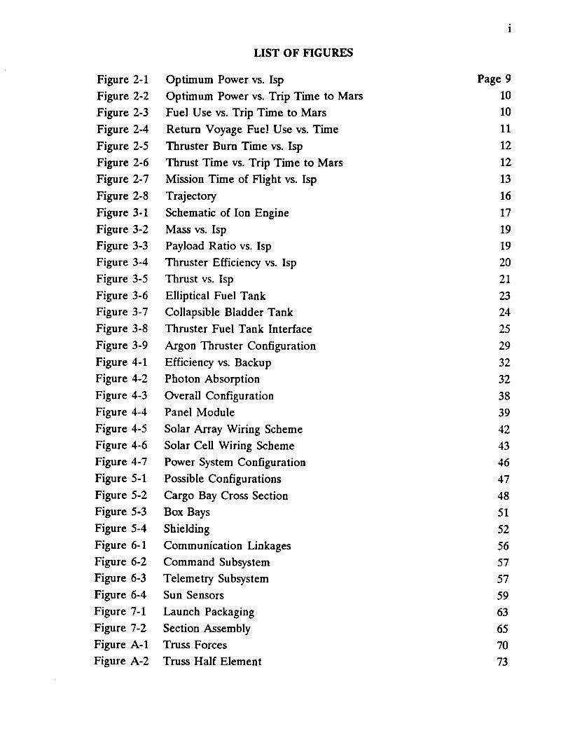
4.1b Radiation Damage
Photovoltaic cells operate with great sensitivity to fluctuations in the presence of
charged particles. Exposure to free electron and proton radiation can damage the
cell material, even to the extent of total loss of power production. Around Earth,
there are particles from cosmic and solar radiation that are trapped in magnetic
fields, forming the Van Allen belts. These belts are a major obstacle to the Mars
mission, which requires a very slow spiral outward from the LEO.
Normal solar cell materials will experience degradation on the order of 20-30% of
their Beginning of Life (BOL) power(31). This reduction would force the ship to
carry oversized solar panels in order to provide adequate power after a three year
journey through space. These panels would also have to be replaced between every
mission, producing an enormous waste of money, time and material.
A promising solution came by considering the use of InP. The normal radiation
resistance of the wafer has been shown to be stronger while it is being illuminated
by sunlight, no matter how intense. In addition, experimentation has demonstrated
that an InP cell exhibits self-annealing from electron-induced radiation damage when
held at a temperature of 100 degrees C for any length of time(18). In fact, in about
ten minutes at that temperature, the cell can completely recover its power producing
abilities even after having been reduced to zero electrical output by radiation
degradation. Assuming that this fact would hold true for proton damage as well, a
radiation hard solar array can be manufactured that would last almost indefinitely,
regardless of how often or how long it is used.
Recent reports have shown that a p/n junction indium phosphide cell can achieve
an efficiency of over 22%. Current optimum cells use n/p structures because they
produced the best results in early experiments. However, Rhoads and Barnett (40)
presented a model for a p/n junction device that has predicted new designs for high
voltage, high efficiency InP solar cells. This new design exploits the high absorption
capabilities of InP, as well as its relatively long diffusion lengths and modest surface
recombination characteristics. This cell uses a very thin emitter layer with a high
doping concentration. Doping is a process of impurifying the semiconductor toenhance the electrical behavior of the cell.


34
4.1c SEMM1 Cell Materials
The multi-bandgap solar cell for the cargo ferry will use a p/n junction InP top cellwith an open circuit voltage of 928 mV and a short circuit current of 38.2 mA/cm z.
The efficiency of the InP evaluated at air mass zero (AM0) is 22.5%. Thecharacteristics of the 5 x 5.4 cm cell are summarized below.
emitter: thickness
doping
.02-.07 micrometers6E+17 1/cm 3
base: thickness 5.0 micrometers
doping 6E+16 1/cm 3
The solar cells will be of a multi-bandgap type, using InP as the top layer and
gallium antimonide (GaSh) as a bottom cell. This combination has been studied and
experimented with at Boeing and Entech (38), who used the cell in their mini-domed Fresnel lens. The GaSb bottom layer absorbs photons of a shorter
wavelength than InP, and will add another 8% efficiency to the total capability of
the cell. The addition of the GaSh bottom cell changes the cell output to 48.2
mA/cm 2 and 714 mV. Operating at high temperatures, however, tends to reduce thecell's efficiency on the order of 4-5%. Losses will also occur due to packing factor,wiring, and mismatch. The power conversion system will also reduce the total
efficiency slightly. A small amount of current will also be drawn from the main feedto be rerun back through the ceils in a forward bias configuration to keep the cell
materials above 100 ° C. Taking into account all of the factors listed above, theeffective power from these solar cells is projected to be 303.6 W/m 2.
The cell conversion efficiencies are summed as follows:
Indium Phosphide 22.5%Gallium Antimonide +8%
Cell Temp. (100 ° C -4%Total 26.5%
The physical and electrical
Packing Factor
Wiring/MismatchPower Conversion
Forward Bias Current
losses are listed below:-5%
-5%-2%-1%
The net cell efficiency is projected to be about 22% near LEO, resulting in a net
power output of 3,148 kW.
The losses to be expected after the Mars journey include:
Abrasions/Clarity - 1%
Impacts/Malfunctions - 1%
Irrevers_le Degradation -1%


35
The InP/GaSb cell will be bonded by an adhesive and sandwiched between the cover
and substrate. The top layer is a cell cover, designed for protection and to eliminate
losses due to obscuration at the edges of the cells. An anti-reflective coating will
help keep the sunlight from bouncing off the covers and wiring on the blanket
surface. The bottom material is a 2-rail thick Kapton polymide substrate. This
material is a carbon-loaded dielectric, and its resistivity is such that it serves as a
ground to prevent electrostatic charge buildup. The substrate must be treated with
a SiO 2 coating that will prevent erosion of the Kapton by atomic oxygen in the spaceenvironment(51).


36
4.1d Evolution of Solar Array Configurations
There are many ways that solar cells can be exposed to sunlight. The traditional flatpanel array has been well proven and technology has produced a very lightweightstructure. Another approach is to use optical concentrators to focus the sun's lighton a smaller solar cell. These reduce the amount of area needed to produce a set
amount of power. Double reflective mirrors are popular and well-proven on Earth,but a 12-meter dish would weigh far too much for space power systems. Tinyreflective concentrators have been produced that weigh less, but are still too heavyto be efficient.
Refractive optics has shown to be very promising, using lenses to diffract incoming
light and focus it onto a solar cell. Mini-dome Fresnel lenses have been developedand are the center of intense research at NASA's Lewis Research Center(38). The
domed concentrators can be manufactured and fitted into a square structure, so that
most of the incoming light is captured. These cells operate at 130 C, which wouldenable a small cell of InP to demonstrate its self-annealing capabilities.
Unfortunately, the Fresnel lens array requires large advances in structural
technology. There is work being done at Boeing that promises to make the
structure very lightweight by hollowing out the interior walls and using stronger,
lighter materials. However, an array that produces 3 MW of electrical power must
be huge, requiring the manufacture of thousands of lenses and the painstaking
assembly of the box-like structure. In addition, as the array grows in size, its
flexibility begins to cause problems, and potential bending can occur at locations farfrom the ship's center. This would require a beefy support structure for the array
of lenses, just to hold it steady, since the lenses can only operate within a sun-
pointing tolerance of -'-1 degree. This may be impractical to achieve on an array of
this size, and may be difficult to erect in space, unless astronauts were to spend
hours constructing it.
The basic flat panel technology is much more usable. NASA has been working on
solar panels for its proposed Space Station Freedom for several years, and has flowna few prototype arrays on the space shuttle. These panels were around 30 meters
long and about 4 meters wide, and demonstrated adequate stiffness and deployabilityunder space environments(51). These types of panels WIll form the power system
for our ship.


37
4.1e SEMMI Solar Array Configuration
The solar array configuration was strongly influenced by three factors: assembly
time, launch packaging, and pointing accuracy. Flat solar panels were chosen over
Fresnel lenses because the structural strength needed to achieve high pointing
accuracy would have added complexity to the assembly and significantly increased
the weight of the arrays. Extendable solar arrays are advantageous in that they are
lightweight, consist of solar panels which require a lower pointing accuracy, are self
deployable, and are compact when stowed. The lower requirement on pointing
accuracy allows us to use a single truss to support each arm. These arms will be
divided into large preassembled sections that can be put into orbit with a heavy liftlaunch vehicle.
The ability to have preassembled sections will significantly cut down on costly EVA
time. The baseline designs for the Space Station Freedom are being redrawn
because the time required for the astronauts to assemble and upkeep the station was
enormous. The new configuration is based in part on sending up the truss sections
pre-assembled, enabling ground testing of the structure that was previously
unavailable. The Mars cargo ferry will take advantage of NASA's decisions and
duplicate their efforts. Since astronaut time is much too expensive to be taken
lightly, automated deployment and pre-assembled packaging may be more importantthat simple weight or size constraints.
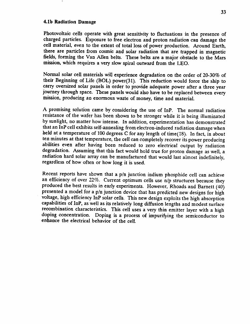
The power system consists of 24 deployable solar arrays that extend out from a long
central truss. The truss is attached to each side of the ship, forming two "wings",
with 6 arrays fore and aft, on each wing (figure 4-3). Each array consists of two
solar panel blankets that are held in tension by a mast extending between them
(figure 4-4). The blankets are 40 meters long and 5.4 meters wide, making them
slightly bigger than the prototypes that were flown earlier. The weight of the solar
blankets including wiring will be 1.0 kg/m 2. Each mast tip will house a small control
moment gyro weighing 8 kg. This gyro will work to keep the blanket array from
bending too far under the effects of thrust or docking impact. One axis of stability
is sufficient because the acceleration of the ship will always be in that direction. The
extendable mast, stowage canister, and stabilizing gyro will account for about 36 kg.
This will bring the weight of each deployable module to about 505 kg.
The solar arrays will be anchored to the truss during assembly. Each array is totally
independent and is connected to the truss only by its base. The array is self-
deployable, and its coilable mast will unwind and lift the cell blanket from its storage
box and pull it taut. The mast longerons and battens are made of fiberglass and the
diagonals are braided steel cable. Each array is 0.6 meters away from its neighbor,giving it enough room to wobble on its own.


_[m!m$1mi$!mmmllL
]$$1_m@WIW$1[Uf""illlil !1 r_ ,N$111111,!II,,,I$11'_._ilL_
iillill1111_i_t_[$NI$iI
,mml llilllUHHl'mH@__,,m,llmtlltlllltl,ulm,t,_ItlitllliUttllllil_il_
g@_NIIIIIIIIIIIIIIIIIIIIItlIIII,!IIIIII
__i__iI_
7 _n rl lilm-Tlllll;_llllllll,mlllllll_HHlll_,,,I,l,,i_
--j
II IIII! I!1 I_lll,IW$1mllhlmllllllllllll, I' j m_IIIIIIIIIII,II$III!I,IIIIII,!!!.[!!II_$
_I__I!ii__L............
1111511151111i!111i111i111111_1111_!!II$I111_!II1II111!!111_.1_
_$1111ml_llllllllll,_J!!_llil!ll_lll]. __l_l_l_ll_
7 I!11 111 II ! 111 1
II III IIIII_ $,qm_ll$111_lln$,bll__l!ll!ilflilill_iI@_
r_ il fil_XNI,IIIIIIN_N
!1 I 111II!11 , TI
c_
ll/
f-'r'-q
LJ_JL_.J__--)C__C_
LL
38

J11
I
I
_ZL_CZ_dTD_
EL3
CO
tq::[3
CZ)
I
LLJC_-7__
C__-b
L_L_
39


40
4.1f Stability and Control Characteristics
The fiat panel is very forgiving of sun-pointing errors. Since the cells absorb the
light which falls directly on them, the sun's intensity will drop offwith pointing error
as a cosine function. This gives the cells 95% sunlight even if the panel is bent away
from the sun by almost 20 degrees. Too much bending can be harmful to the
structure, however, so the small control moment gyro is fixed to the tip of each array
mast, giving it active control and holding it nearly level. The array has a natural
fi'equency of 0.2 Hz and a stiffness of 0.015 g(51). This is adequate in the space
environment, and the gyro ensures that the arrays will never oscillate at resonance.


41
4.2 Wiring
The solar power is generated by twenty four individual deployable solar arrays.
Each of these arrays is 40 m x 10.8 re(solar material only), and is divided in half
lengthwise. The wiring scheme for one of these halves is shown in figure 4-5. The
individual solar cells are 5 em long and 5.4 cm wide. The 40 m x 5.4 m section is
also divided in half. The two halves shown in figure 4-5 contain 800 rows of 50
cells. In order to avoid creating any sort of magnetic field all wiring will be run
symmetrically starting and ending on the outer edge of each side of the array
blanket. The cells will be wired in strings of 200 cells, or four rows, in series. This
will amount to a line voltage of 142.8 V and a current of 1.263 A for each string.
Cells A, B, and C, shown in figure 4-6 demonstrate the wiring scheme used to wire
the strings of solar cells. Because the cells are wired in series some special safety
measures have to be taken. If one cell were to be damaged or destroyed by debris
or by some other means the current generated by all of the cells "upstream" would
be lost. In order to prevent these losses each cell is wired with a reverse bias
configuration. Wires 1, 2, and 3 create an alternate path for the current to take if
one of the cells should malfunction or become damaged. Each wire is fitted with
a reverse bias diode which gives the wires an infinite resistance relative to wire 4
which is the proper current carrying wire. But in the case of a malfunction where
current cannot pass through wire 4 because of a break, wire 4's resistance would go
to infinity relative to wire 2's for example and the current would break through the
reverse bias diode and flow around damaged cell B and back into wire 4.
The key to the annealing capabilities of the InP/GaSb solar cells is the operating
temperature. For complete annealing of radiation damage, the InP material
operating temperature must be above 100°C. In order to ensure this the Inp cells
are wired with a forward bias configuration. This is shown in figure 4-6, where cells
A, B, and C are wired with a forward bias configuration. After power is collected
by the string of cells and passed along wire a small portion of the current is bled
off and fed back through the cells themselves. The current can be divided by
creating a 99:1 resistance ratio where 99% of the current would run through the
wire with a relative resistance of 1, and 1% of the current would run through the
wire with a relative resistance of 99. One percent of the total power should be
enough to ensure that the operating temperature of the cells would remain above
the 100°C mark. InP, being a semiconductor has a high resistivity and by a process
similar to that of a light bulb filament the InP becomes heated when the current
passes through it. It is assumed that the GaSb portion of the cell will receive
negligible radiation damage due to the Kapton and silicon dioxide coatings behindit and the InP above.


L_L_J
C1r_J
L_Jl
4Z


43
J
CJ-_
tllCJ__
kl_J
! .J_J
t
f\
\i
• Yf_
,"x
I,J
N
V!'
I
L.___
C_
Y. _ "
\ /_.,,
/'V
/x., :
\/\1
__j _1
OD
k_--_
LL_.3
C_._3I1
I


44
Each half array contains a total of 400 strings. These strings are added together in
parallel giving each whole array an output of 1010.4 A at a voltage of 142.8 V. They
are added in parallel to keep the voltage below the design limit of 200 V to avoid
arcing between the solar cells. The total power provided from the twenty fourindividual deployable arrays is 24249.6 A at 142.8 V whose product yields a power
of 3.463 MW, not discounting for degradation, resistive heating, wiring mismatches,etc.
All wires on the arrays are made of aluminum. Aluminum wires have a lower mass
and a larger surface area than copper wires. This additional surface area allows the
aluminum wires to radiate heat more efficiently than copper wires. In order tomaintain an optimum level of electrical efficiency the wires must be kept cool
whenever possible. Therefore the wires are attached and run along the shadow side
of the solar arrays. The heavy wiring along the trusses is sized so that the powerloss will be less than 80 kW.


45
4.3 Power Distribution and Management
Before the power from the arrays can be used it must first be conditioned into aform which can be used by the on-board systems and the thrusters. The current isrun through a DC-AC converter then through a high frequency single phase
transformer and power rectifiers. The power is distributed to on-board systems bythe Power Distribution and Control Assemblies (PDCA). The essential part of thesystem constitutes power processing units (PPU) supplying power to ion thrusters
(see section 3.3). The PDCA's are controlled by electrical power system software.The power system configuration is shown in figure 4-7(29).
SEMM1 is equipped with an auxiliary power system made up of two Nickel
Hydrogen (NiH2) batteries packs. This system needs to run the ship when the solar
arrays are in the shadow of the Earth (or Mars) and are not producing any power.
The maximum shadow period, calculated from the trajectory of the ship, lastsaround six hours. NiH2 batteries can produce up to 100 Watt-hours per
kilogram(18). This makes them obviously too heavy to consider powering the main
thrusters during shadow periods, so they are only used for housekeeping purposes
like running the computers, communications, attitude control systems, and thrusterstarting controls. The battery system on SEMM1 can deliver up to 2 kW of power
for nine hours. They are recharged continuously by extra power from the solar
arrays. Two separate battery packs are used as a physical safety factor in the case
that one of them may fail.


i
Z
I
t_4_A
C r-D
t__k_
46


5. VEHICLE STRUCTURES
47
5.1 Truss Evolution
The initial configuration of the cargo ferry were based on using the mini-domed
Fresnel lens system as stated in the Introduction. However, the problems involvedwith the supporting structure of the Fresnel lens array were judged as very difficultand serious. First, the accuracy of the array pointing must have been __1°. This
would be difficult to achieve without a very rigid panel, not to mention a possibly
wobbly array. The system would have to be assembled on the large structure inspace. Such an assembly would have required many hours of astronaut labor, and
would have been very costly.
The next design step was to adopt the flat panels as the method of choice. When
it was realized that the individual flexible blanket arrays could be mounted to a
space station-like truss, efforts turned toward choosing the proper materials,
strengths, and beam dimensions. Starting with graphite/epoxy, as the basic truss
material, calculations quickly showed that the truss structure was inherently very
strong. Large forces could be applied tc the beam with a very small deflection at
the end. The next approach was to try to reduce the beam weight by using thinner
and lighter rods, but it was found that the beam mass and strength remainedrelatively constant.
An important question at this point was how to shape the truss. One long trussbeam seemed just as feasible as an H-shaped configuration, these configurations can
be seen in figure 5-1. The comparison favored the long single beam, since simplicityis the key to easy assembly. The single beam created a greater moment on the
alpha joints, but it reduced the moment of inertia of the wings, making them mucheasier to rotate.
FIGURE 5-1


48
Focus then turned to rough optimization of the launch packaging capabilities. Weassumed that a heavy lift vehicle (HLV) with an 8 meter diameter by 30 meter longcargo hold would be available at the time of our assembly. It was decided to launchthe beam in preassembled sections to cut down on costly EVA time. This decision
became a limiting factor in the beam dimensions. As seen in figure 5-2, four beam
sections with 2.6 meter long sides will just fit into the HLV cargo bay. The arrays
were placed in the bay, unattached, but alongside the truss, to be attached to thebeam once in space.
8 meterdioneberby 30 neter longcargobey
////
2,5 ne_erbQysolar array support;orns
FIGURE 5-2


49
5.2 Materials Selection
The truss structure of SEMM 1 must be strong enough to support solar arrays aboutthe size of a football without deflecting too much at the ends. The key component
of modern space structure is a composite tube. A composite tube must not onlystrong, but must be able to withstand thermal cycling as well as deterioration due
to radiation and atomic oxygen.
Thermal cycling in LEO typically is between 150 and -100 degrees Fahrenheit. This
presents a problem for some composite materials because they develop microcracks
when thermally cycled. A suitable composite for our needs must have a low
coefficient of thermal expansion (CTE), to minimize dimensional changes throughthe temperature cycle. Table 5-1 shows the modulus of elasticity and the CTE for
several composites. Also included is an assessment of radiation resistance.
Material
Gr/EpoxyGr/Glass
Gr/AIAluminum
Titanium
Gr/Mg
E (psixl06)
39
31
47
10
17
high
CTE(in/in/Fxl0 6)
-0.6" / 18""-0.3" / 3.6""
0.8" / 15 .°
13
5
-0.04 to 0.16 "°
Radiation
Resistance
good
good
Excellent
* Longitudinal ** Transverse
TABLE 5-I COMPOSITE MATERIALS COMPARISON
Gr/Mg seems to be the overall best candidate for space structures, but it has one
major problem. If it is cycled to temperatures reaching -200°F it will experience
cracking and poss_le fracture. The choice then becomes difficult because Gr/AI and
Gr/Epoxy are statistically very similar. Gr/Al has a higher modulus of elasticity, but
Gr/Epoxy has a higher-ultimate axial tensile strength of 1.34 x 10 9 N/m 2 than
titanium which has an ultimate tensile strength of 1.10 x 10 9 N/m 2. Gr/Epoxy also
has good resistance to radiation.
The poss_ility of using a coating to protect the structure from UV radiation and
atomic oxygen exists. A thin coating of reflective Aluminum on the composite tubes
would improve radiation protection and keep down the temperature of the structure
when exposed to the sun.
Gr/Epoxy tubes combined with titanium nodes seem to be a good combination
because they have similar CTE's. This means that they will contract and expand
similarly thus reducing stress and strain on the joints where they are bonded
together. Titanium nodes were chosen purely for their higher strength than that ofaluminum.


50
5.3 Truss Element Calculations
The power structure truss reaches out 72.8 meters past the alpha joints, and is built
of hollow composite struts, attached by multijointed nodes in a boxlike beam, as
seen in figure 5-3. The truss is strong enough that even at extreme inertial loads,
such as those created on impact with a Space Station, the tip of the truss will bend
less than 0.5 meters. The truss will be launched in six fully assembled sections, tobe connected in LEO.
The truss elements will be made of graphite/epoxy and will be connected by titaniumjoints. The truss elements will be hollow with a 3 cm outer diameter and a 1.5 mm
wall thickness, as seen in figure 5-4. Each element will be protected with a 0.1 mm
coating of anodized Aluminum. The calculations for the truss element dimensions
are presented in Appendix C. The density of graphite/epoxy is 1522 kg/m 3, and the
density of titanium is 4510 kg/m 3. There will be 28 box bays per arm, so there will
be 228 truss elements 2.6 meter long (0.53 kg each), 141 truss elements of 3.7 meter
long (0.76 kg each), 116 node joints (1 kg each), and 12 interface components (9 kgeach) where the panel modules attach.
Mass Summary:
2.6 m elements
3.7 m elements
node joints
interface components
121 kg
106 kg
116 kg
108 kg
total truss arm 451 kg
This arm weight does not include electrical wiring or the weight of the alpha joints.


51
SEAR ARRAY
SUPPORTTRUS__
PANELINTERFAEE
BAY
FIGURE 5-3
Mass summary of the solar power system is given in Table 5-2.
24 Solar Arrays
Wiring
Trusses, t_-rotational joints
with sliding electrical connectors
12,120 kg
1,400 kg
1,800 kg
Total Mass 15,320 kg
TABLE 5-2 POWER SYSTEM MASS SUMMARY


52
5.4 SHIELDING
Outer space has some serious environmental problems. These include space debris,
micrometeorides, atomic oxygen, thermal cycling, charged particles and ultraviolet
radiation. Space debris held in orbit about the earth have very high velocities. The
cargo vehicle will have to travel through regions where there will be a high
probability of impact by micrometeoroids and space debris, so shielding must be
provided for the ship's vital systems. The fuel tank, the navigation/communication
systems and the cargo module will need to be protected. The tank shielding is
discussed in Section 3.1. The shielding will consist of a series of corrugations backed
by two bumper plates spaced away from the spacecraft wall, as seen in figure 5-4.
The corrugation will enhance the protection and help prevent the creation of
ricochet debris(42) which could strike other parts of the spacecraft. The large solar
arrays cannot be shielded from space debris, so we have allowed for degradation due
to debris collisions by making the solar arrays about 2% larger than necessary, and
this will also serve to account for degradation due to solar radiation. To reduce
degradation caused by thermal cycling, abrasion and exposure to atomic oxygen, the
structural parts of the craft will be protected by coating with anodized Aluminum.
iFIGURE 5-4


53
6. GNC & COMMUNICATIONS SYSTEMS
A Guidance, Navigation and Control system and a Communications System are vitalto the success of the mission. The communications system provides data and imagetransmissions to Earth so that the mission can be monitored and controlled.
Corrections and adjustments that need to be made are then transmitted back to the
spacecraft. Any maneuvers that need to be made are then performed.
6.1 COMMUNICATIONS
In designing a communication system several factors must be examined. The firstcritical option is the amount of information that must be transmitted. Second is the
amount of time available to the craft for the actual transmitting of the data. Lastly,the distance over which the data must be sent. With the maximum data rate set at
20 Mbps, the decision became a trade-off between antenna size and broadcast
power(39).
To support our communication system, several assumptions were made as to thetechnological developments that will occur by the launch of the spacecraft. First,
NASA's Deep Space Network (DSN) will be upgraded to a quad 34 m Ka-band
system giving an effective aperture of 70 m. Secondly, there will be two Mars RelaySatellites (MRS) in a stationary orbit 120 ° apart. Lastly, there will be some
distributed Mars Surface Terminals (MST).
Analysis of the return links was emphasized due to the fact that uplinks from the
Earth were far less critical. Building large antennae and acquiring the powerneeded to operate is far easier to accomplish on Earth than in deep space.
The communications system is composed of the two MRS, DSN, the MST and thecargo ferry. The MRS provide all intrasystem communications and the major
communication links with Earth. The advantages of this system, as opposed to onewith less or no MRS, is that there is near 100% coverage and provides full
connectivity. The communications system operates at Ka-band (32.05 GHz).
The spacecraft itself will carry four antennae: two fully directional parabolic
reflector antennae and two spiked-horn omni-directional antennae. The parabolic
reflectors are 5 m in diameter and the omni-directioanl antennae have a length of
0.5 m(39). The antennae are made of a graphite-fi%er-epoxy (GFE). The parabolicreflectors are used for the majority of the communications needs. The omni-directional antennae are used at close ranges, such as for communications with MRS
while in orbit at Mars and docking maneuvers.
The MRS to DSN is the most critical link. A data rate of 10 Mbps is achieved using
a 9 m MRS antenna. This requires 180 W of power. Crosslinks between the MRS
can reach data rates of 40 Mbps with antennae diameters of 1 m and 2.3 W of
power. For direct links between the spacecraft and DSN, the 5 m parabolic reflector

54
requires 182 W of power and can transmit 10 Mbps. For links between thespacecraft and MRS, the 0.5 m long omni-directional antenna is used. This requires
only 6.6 W of power.(39) These links are summarized by figure 6-1 and table 6-1.The mass and power of the components of the system are given in table 6-2.
The command subsystem is responsible for uplinks to the spacecraft.
commands and data commands are the two basic command types.
Relay
Relay commands may be simple on/off type functions or initiate a step-by-step
procedure. Data commands give information upon which the spacecraft acts. Forexample, firing a thruster to correct the actual trajectory would be a combination ofrelay and data commands. Data commands might include instructions fororientation of the craft and time to burn. The relay commands could be switching
from one antenna to another. This also illustrates the need for delayed commands.
If the burn needed to be planned ahead of time, it would not be wise to wait until
just before the burn is to occur to transmit the command. So, transmitting the
whole sequence of events ahead of time is necessary.
The commands are received by the antenna and sent to the receiver. The receiver
amplifies the signal and filters it to achieve a "cleaner" signal and to get rid of
unwanted signals and noise. The command then goes to the command processor
where it is interpreted. The simple commands then go straight to the power
switching unit and are executed. Delayed commands are stored for action at a later
time. More intricate commands are sent to the computer to be sorted out before
execution. This command subsystem is depicted in figure 6-2.
The telemetry subsystem (figure 6-3) is the opposite of the command system, so to
speak. Where the command system dealt with receiving signals, the telemetrysubsystem deals with transmitting data. Sensors respond to some event, such as an
acceleration, and send it to be converted into an acceptable form for transmission.
Weak signals are amplified and strong signals are attenuated. If transmission ispossible the signal is sent. Otherwise, the data is stored and transmitted at a latertime.


55
DATALI_
• 8 TO_
TOGT
• _1 IOGT
MGlTOHit
_.6
32.6
32.6
2.3
8.G
57
llIAlx041l
A,NIEJ_kUIA_(:I_
(m)
1.0
gO
0.5
50
05
_IV[R
_ff:l'l_AULA_EI_
(m)
1.0
70O
)0
70O
).0
40.U
lO.O
_.0
]8
_0.0
_J
TABLE6-I
P_ IC_FLECICII
L)4G
FF_ GAS7IT
(:l_rlTY(kg)
FC_RSI2'F
(W)
80 2400 6LIIE_
)0
I_U
0.77
015
)B20
G6
_0
)GO
_0
5m DIAl4
05m OI_
0_ mUI_ x,JL3,'sL_IH
0% mOl_ AO_ ,_L[)(Glll
O.3m DIAMxD5 mLEhR)TH
TAE)LE6-2


$6
"'x _.,("
/ \}
QI-2
I I
\
\\\\\
\\\
I
L_U
C___I---I


$7
SEMMICOMMANDSYSTEM
I_CEIVER
4L_K}
I]A[A
r"Ico_!LR
hE-LAY
"/ _JWIICHI_
\\I UNIT,T',L_LAYED'\ ICC__IMANDS--\/ i
"---\/ i\ r-''w-- --.4__ l
I a_oARDI
FIOURE5-2
SPACE
SEMM]TELEMETRYSYSTEM/
/
CO_]ITIONINGI
",, / .i../..
FOlk'fAIlING SILAGE J
FIOURE_-3


58
6.2 Guidance, Navigation, Control
The cargo ferry requires a command management system that can bring it to Mars.
The guidance, navigation, and control systems are necessary to keep the ship oncourse. Another important function is to keep the solar arrays facing the sun. Wellbefore the craft is launched, the planned trajectories as well as alternate routes andcontingency plans are fed into the computer by engineers. The ship's computershandle aH functions on the ship, but draw less than one kilowatt of power. There
are two computers for every function, since electrical failures can be expected tooccur.
Once launched from Space Station Freedom, SEMM1 must receive data from
various sensors, such as star trackers, that fix the ship's position in space.
Information on location and attitude must be compared to the model trajectorystored in memory. A feedback control law issues commands to the ship's control
system to correct errors in flight path.
The ship's navigation system uses a system of Inertial Measurement Units (IMU),
scanning telescope, spacecraft transponders and a guidance and navigation
computer.
Sun sensors on the solar arrays are used to track the sun during the journey through
space. There are four double-axis sun sensors on the upper surface of each truss
beam. They are small boxes, illustrated in figure 6-4, no more than 1 kg in weightand are mounted at the end of each arm. These sensors use square apertures above
photocells to detect changes in the direction of incident sunlight (53). This
information is fed into the computers which relay commands to the control moment
gyroscopes (CMG) to slowly turn the solar arrays. The accuracy of the sun sensors
is much more precise than the arrays actually need due to their pointing tolerance.


59
III I I
_J
Imc.Z______[__
V-1
I
/ \ /! \ \
\ \_/ '(%'_ /,,/
_______
I I I
J
_.---x---C
I0
I
II
L__
L__.__!____
L__L__


60
The ship must have controls that determine pitch, yaw, and roll, where the x-axis is
assumed to pass from the cargo to the thrusters. The acceleration vector of the shipwill most always be along this axis under thrusting conditions. Small corrections will
be made by the control system, made up of a trio of control moment gyros andseveral small thrusters mounted on the structure.
The control moment gyros (CMG) provide the primary rotational control for the
vehicle. This motion produces a powerful pure moment vector that in essence is
fixed in space. Any perturbations to this vector wil result in a restoring motion that
will keep the vector pointed in its original direction. This can be used by the ship
to control its attitude. Electrical motors are used to turn the gyro's mountings,
disturbing its direction. When the gyro torque corrects its orientation, the entire
ship is forced to rotate opposite to this motion.
SEMM1 will use four such gyros, housed in the central body module. They produce
a pure couple that will rotate the ship independent of its location. Three gyros willpoint in each of the three coordinate axes, while the fourth serves as redundancy.
A gyro currently made by Bendix is recommended as the baseline standard, though
improvements in technology may well provide a significantly improved gyro. The
example is detailed as follows:
Weight:
Rotor Speed:
Maximum Output Torque:
Gimbal Freedom (deg):
Approximate Size:
190 kg
4,000 rpm250 Nm
unlimited
cylinder 1.25 m diameter X
.50 m long
TABLE 6-3
Very slow rotations about y (array truss direction) and z-axis, required during main
thrusting for midcourse corrections, can be accomplished by differential thrust
and/or gimballing of the main thrusters.
The secondary control system is designed for rotations about x (roll) and y-axis andfor small translational adjustments. The system can be provided by small ion argon
thrusters mounted at the corners of the main body structure. These thrusters woulduse the same power source and propellant tank as the main thrusters. Such a
system provides a virtually unlimited attitude control capability. Alternatively, a cold
gas system may be applied. The cold gas system operates more consistently than a
hot gas jet, particularly when the system is operated in a pulsed mode, because there
is no chemical reaction which must reach steady state. The low thrust level
therefore facilitates more precise control(53). This system is only necessary in thedocking maneuvers required at Mars and with Freedom and/or for desaturization
of CMG's. Each gas thruster includes its own small fuel tank of freon propellant,


61
and produces one newton of thrust while thrusting. The jet is only 0.5 meter longwith a nozzle diameter of 0.3 meter.
Twenty-four jets will be mounted on the corners of the body module, three on eachcorner, one pointing in each direction. Each face therefore has four jets that will
provide 4 N of thrust perpendicular to that face. Combinations of firings can
provide translational motion in any direction. The gas system has multipleredundancy, since up to three jets can fail on any face. The jets also serve as a
redundancy for the CMG attitude control and a last ditch source of power in caseof an unlikely ion thruster shutdown.
Both systems respond to commands from the central control system found in the
main body housing. This system monitors the ship's position and uses an errorfeedback loop to make corrections.

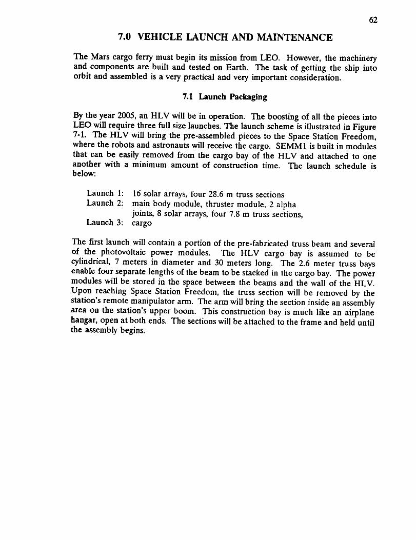
62
7.0 VEHICLE LAUNCH AND MAINTENANCE
The Mars cargo ferry must begin its mission from LEO. However, the machinery
and components are built and tested on Earth. The task of getting the ship into
orbit and assembled is a very practical and very important consideration.
7.1 Launch Packaging
By the year 2005, an HLV will be in operation. The boosting of all the pieces into
LEO will require three full size launches. The launch scheme is illustrated in Figure
7-1. The HLV will bring the pre-assembled pieces to the Space Station Freedom,
where the robots and astronauts will receive the cargo. SEMM1 is built in modules
that can be easily removed from the cargo bay of the HLV and attached to oneanother with a minimum amount of construction time. The launch schedule is
below:
Launch 1:
Launch 2:
Launch 3:
16 solar arrays, four 28.6 m truss sections
main body module, thruster module, 2 alpha
joints, 8 solar arrays, four 7.8 m truss sections,
cargo
The first launch will contain a portion of the pre-fabricated truss beam and several
of the photovoltaic power modules. The HLV cargo bay is assumed to be
cylindrical, 7 meters in diameter and 30 meters long. The 2.6 meter truss bays
enable four separate lengths of the beam to be stacked in the cargo bay. The power
modules will be stored in the space between the beams and the wall of the HLV.
Upon reaching Space Station Freedom, the truss section will be removed by the
station's remote manipulator arm. The arm will bring the section inside an assembly
area on the station's upper boom. This construction bay is much like an airplane
hangar, open at both ends. The sections will be attached to the frame and held until
the assembly begins.


C_J____9¢-'C-
C_II
L_L_
! ,//I JM¢
/ _
.o
/
/
_ N
/ mJ //
Ill : _
/Uf i¢'
C_.rDr-Y-I I I
C.J_.J C.¢-;J F--
r-w- r-T----T-- F_ ___J
_'-_. C_; L__L__JL_LJ r-q
CZD _CC] On_ EZL__
\ i.I_ _ ;
/ /
4 /
/IM/ ¢
_ /__r, _
0
I
63


64
7.2 Assembly
Actual assembly of the pieces, if conducted in early 2000, will most likely use space-
suited astronauts who will manually bring the sections together, as shown in Figure7-2, joining the final struts and nodes. This EVA method of construction would be
very costly, time consuming and subject to hazards.
By 2010 telerobotic methods of construction combining the durability of a robotic
manipulator and the intellect of a human operator may become available. The man
will operate the robot arms from the safety of a crew workstation, using joysticks orelectrically wired gloves that relay the man's movements directly to the robot'smanipulators. Telerobotics may be ideal for construction of SEMM1 since the final
assembly will be simply a matter of attaching one node to a strut, something therobotic arms could handle easily.
The two solar array support arms are each over 70 meters in length, so upon
completion they must be attached side by side to the exterior truss of the space
station, above the upper keel. The truss is so light that its presence will notadversely affect the performance of the station, nor will its thin members block
sunlight to Space Station Freedom's arrays.
The second launch will contain the main body module, the thruster module, the
alpha joints, the propellant tank, and additional power modules. Except for the
truss and arrays. Once the tank is installed on the body, the solar array support
arms will be carefully fixed into the sides to complete the assembly. The final
SEMM1 assembly must take place on the upper boom of the space station, as the
pieces are simply too large to fit in the garage. The ship will remain completed on
the upper boom until the cargo arrives for the trip to Mars.


"1-- r-
m _IF-
'!
I' !
1
I-- IJ
-I [..ql
u
II
1
ii
= qlt
t
U
__1
C.J -Cj_J
f_-'\ 1
l '- J
1
LL.J
L J_
65

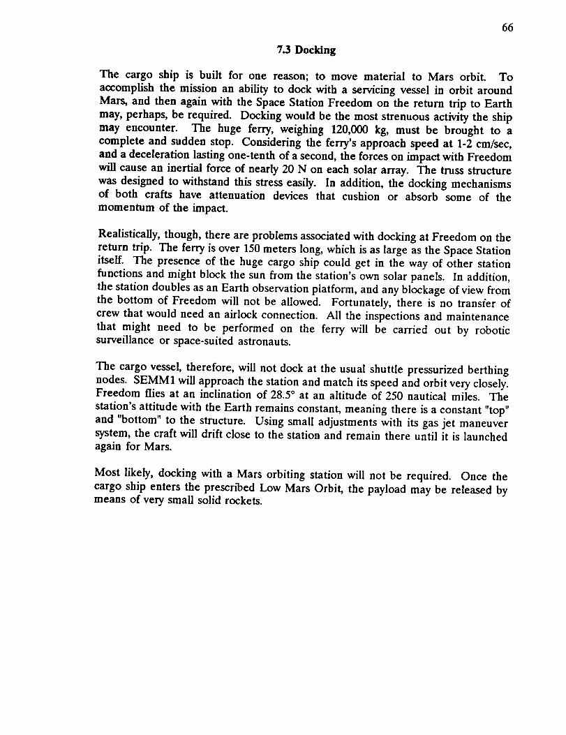
66
7.3 Docking
The cargo ship is built for one reason; to move material to Mars orbit. Toaccomplish the mission an ability to dock with a servicing vessel in orbit around
Mars, and then again with the Space Stat/on Freedom on the return trip to Earth
may, perhaps, be required. Docking would be the most strenuous activity the ship
may encounter. The huge ferry, weighing 120,000 kg, must be brought to a
complete and sudden stop. Considering the ferry's approach speed at 1-2 cm/sec,
and a deceleration lasting one-tenth of a second, the forces on impact with Freedom
will cause an inertial force of nearly 20 N on each solar array. The truss structure
was designed to withstand this stress easily. In addition, the docking mechanismsof both crafts have attenuation devices that cushion or absorb some of the
momentum of the impact.
Realistically, though, there are problems associated with docking at Freedom on the
return trip. The ferry is over 150 meters long, which is as large as the Space Station
itself. The presence of the huge cargo ship could get in the way of other station
functions and might block the sun from the station's own solar panels. In addition,
the station doubles as an Earth observation platform, and any blockage of view fromthe bottom of Freedom will not be allowed. Fortunately, there is no transfer of
crew that would need an airlock connection. All the inspections and maintenance
that might need to be performed on the ferry will be carried out by robotic
surveillance or space-suited astronauts.
The cargo vessel, therefore, will not dock at the usual shuttle pressurized berthing
nodes. SEMM1 will approach the station and match its speed and orbit very closely.Freedom flies at an inclination of 28.5 ° at an altitude of 250 nautical miles. The
station's attitude with the Earth remains constant, meaning there is a constant "top"
and "bottom" to the structure. Using smaU adjustments with its gas jet maneuversystem, the craft will drift close to the station and remain there until it is launched
again for Mars.
Most likely, docking with a Mars orbiting station will not be required. Once thecargo ship enters the prescr_ed Low Mars Orbit, the payload may be released by
means of very small solid rockets.


67
7.4 Maintenance
The ferry will remain close by for severalmonths while all systems are checked outby free-flying robotic surveillance equipment. These miniature satellites can scan
and detect any crack, stress, or deformation to the structure and arrays. In addition,the computers will be run through a full diagnostic routine before implantation ofnew commands and trajectories begins.
The ship is designed to last for three journeys to Mars and back. This will go on
over a lifetime of twelve or more years. The solar arrays should not needreplacement unless a cataclysmic collision has occurred. The truss should last at
least fifteen years, especially with the protective anti-deterioration coating.Defective ion thrusters can be changed out either by the servicing satellites usingtelerobotic control (preferred) or a space-walking astronaut. Malfunctioning interiorequipment will be harder to replace, so a hatch has been installed that will allow an
astronaut access to the electrical components.


68
8.0 DESIGN SUMMARY
The cargo ferry outlined in this paper was designed to bring a load of machinery ormaterials to Mars. The ship uses photovoltaic solar cells to power ion thrusters and
follows a trajectory of spirals; first out from Earth, then around the sun, finallyspiralling down to low Mars orbit.
The spacecraft mass summary and the main specifications are shown in Tables 8-1
and 8-2 respectively.
kg
Cargo 61,000
Cargo Housing/Protection 2,000
Argon Propellant 23,840
Tank, Propellant Handling System 850
Propulsion System (including PPU) 9,750
Solar Panels 12,120
Solar Array Support Truss, a-Joints, 1,800
Sliding Electrical Connectors
Wiring 1,400
Main Body Structure 1,200
Auxiliary Power (Batteries), PDSC 1,050
GMC, RCS 2,100
GNC/Communication System 800
Payload Release Equipment and/or 400
Docking Mechanisms
TOTAL MASS 118,130 kg
Table 8-1 SPACECRAFT MASS SUMMARY

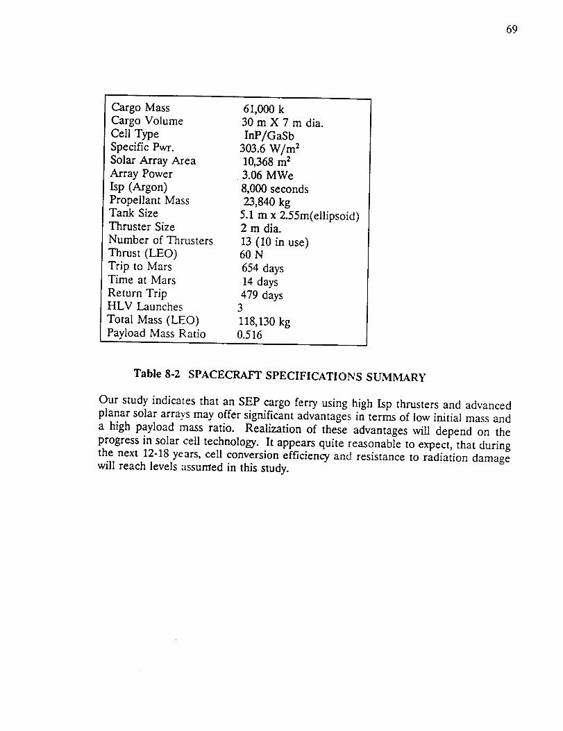
69
Cargo Mass
Cargo Volume
Cell Type
Specific Pwr.
Solar Array Area
Array Power
Isp (Argon)
Propellant MassTank Size
Thruster Size
Number of Thrusters
Thrust (LEO)
Trip to MarsTime at Mars
Return TripHLV Launches
Total Mass (LEO)
Payload Mass Ratio
61,000 k30 m X 7 m dia.
InP/GaSb
303.6 W/m 210,368 m 23.06 MWe
8,000 seconds
23,840 kg
5.1 m x 2.55m(ellipsoid)2 m dia.
13 (10 in use)60 N
654 days
14 days
479 days3
118,130 kg0.516
Table 8-2 SPACECRAFT SPECIFICATIONS SUMMARY
Our study indicates that an SEP cargo ferry using high Isp thrusters and advanced
planar solar arrays may offer significant advantages in terms of low initial mass and
a high payload mass ratio. Realization of these advantages will depend on the
progress in solar cell technology. It appears quite reasonable to expect, that during
the next 12-18 years, cell conversion efficiency and resistance to radiation damage
will reach levels assumed in this study.


7O
APPENDIX A
Truss Element D4mension Calculations
In designing structures one uses the largest anticipated loads, for ourcase that would be docking. In deriving the loads we assumed docking with
the Space Station Freedom, an approach speed of 2 cm/sec, and an impulseof 0.25 sec.
m_ * V I = n_ * V 2
135,000 * .02 = (135,000+500,000) * V 2
====> Vz = 0.004252 m/sec
V, - V 2 .02-.004252
_t 0.25= 0.0630 m/sec 2
mass of solar panel modules = 490 kg
.... > F = m * a = 490 * 0.0630 = 31 N
Bx
Ax
t t t t t tt t t t t
Ay
31 NEWTIINFEIREES
ATEACHPANELMI]DULE
FIGURE A-1
Find element diameter for critical buckling.
M A = 62(6.5 + 19.5 + 32.5 + 45.5 + 58.5 + 71.5) - Bx(2.6 ) = 0
B x = 5580 A X = 5580 A v = 372 I = --(r24-rl 4)4


71
PCR =
_;EI
Lt 2
E " 2.689 * I0 _I N/m 2
FIXED-PINNED
L. = 0.7(2.6 m) = 1.82 m
P_ = F.S.* B x = 1.5 * 5580
- 8370 N
==I=> I IP_ L, 2
E
ff
-- (r2'-rl 4)4
====> (r24-rl 4) I
4 Pen L, s
E
4 (8370) (1.82) s
,_ (2.689 * i0")
(rs4-r, 4) = 1.33 * 10 ,8 m 4 I 1.330 cm 4
for element thickness of 1.5 mm.
==1=> r s = r I + .15 cm
.... > r 2 = 1.40 cm & r_ = 1.25 cm
rounded up to nearest quarter cm for outer diameter
.... > d 2 = 3.00 cm & dl 1 2.70 cm
Calculation of critical stress
A = _ (rs2-r, s) = 1.343 * 10 .4 m s
Pc, 8370 1 psi
a_ .... 6.232 * 107 N/m s x
A 1.343 * 10 .4 6895 N/m s
acR = 0.9039 ksi << 24,000 ksi (strength of Graphite/Epoxy)
( in compression )


Calculation of stress due to bending moment
V = 1.343 * 10 .4 m 2 x [ 224(2.6 m) + 84(2.6V2 m)] = 0.1197 m 3
A = V/L = 0.1197/72.8 = 1.644 * 10 .3 m 2
for a square where s - side length and c = s/2
.... > s = 0.0406 m .... > c = 0.0203 m
see figure 5.2-2 for moment calculation
M = F.S.* Bx * 2.6 = 1.5 * 5580 * 2.6 I 21,762 N m
M c 21762 (0.0203) 1 psia = -- = = 1.951 * 101° N/m 2 x
I 1/12 (0. 0406} 4 6895 N/m 2
o = 282 ksi << 24,000 ksi
Calculation of shear stress
V * Q 2 * r r_ + r 2
T= y= r=I * t _ 2
V = 372 N
I =
t = 0.015 m 4--(r24-r, 4) = 1.010 * 10 .8
72


73
Rl,
×
FIGURE A-2
Q=A*y
Q
1.343 * 10 .4 0.0140 + 0.0125
2
=5.664.10 `7
1.5 * 372 * 5.664 * i0 "7
1.010 * 10 .8 * 0.015
= 1.916 * 10 e N/m 2
7 = 1.916 * I0 e N/m 2 x
1 psi
6895 N/m 2
= 277.9 psi
r = 0.2779 ksi < 12.6 ksi (shear strength of graphite/epoxy)


74
REFERENCES
(1) Axif, Hugh, Aydelott, John C., and Chato, David J., "Evaluation of Supercritical
Cryogen Storage and Transfer Systems for Future NASA Missions," Paper N90-
10912, January 1990.
(2) Barnett, Allen, and Rhoads, San&a, "Modelling and Design of High
Performance Indium Phosphide Solar Cells", Paper N89-24712, 1989.
(3) Bate, R.R., Mueller, D.D., and White, J.E., Fundamentals of Astrodynamics,
Dover Publications, Inc., New York, 1971.
(4) Beattie, J.R., Matossian, J.N., and Poeschel, R.L., and Rogers, W.P., and
Martineni, R., "Xenon Ion Propulsion Subsystem", AIAA Paper No. 85-2012,
Hughes Research Labs, Malibu, CA./Hughes Aircraft Company, El Segundo,
CA./EDAC Inc., Torrance, CA., 1985.
(5) Bechtel, Robert T., and Rawlin, Vincent K., "Performance Documentation of the
Engineering Model 30-cm Diameter Thruster", AIAA Paper No. 76-1033, NASA
Lewis Research Center, Cleveland, OH., 1976.
(6) Bechtel, R.T., Trump, G.E., and James, E.J., "Results of the Mission Profile Life
Test," AIAA Paper No. 82-1905, NASA Marshall Space Flight Center,
AL./Xerox/EOS, Pasadena CA.
(7) Biron, J., "An Aluminum Collapsible Bladder Tank for Space Systems," AIAA
Paper 90-2058, 26 'h Joint Propulsion Conference, Orlando, FL, July 1990.
(8) Braun, Robert D., and Blersch, Donald J., "Propulsive Options for a Manned
Mars Transportation System", AIAA Paper No. 89-2950, Vigyan Research
Associates, Hampton, VA./ANSER, Arlington, VA., 1989.
(9) Brophy, J.R., and Aston, G., "A Detailed Model of Ion Propulsion Systems",
AIAA Paper No. 89-2268, Electric Propulsion Laboratory, Inc., Lancaster, CA.,1989.
(10) Byers, David C., Terdan, Fred F., and Myers, Ira T., "Primary Electric
Propulsion for Future Space Missions", NASA TM-79141, NASA Lewis Research
Center, Cleveland, OH., 1979.
(11) Byers, D. C. and Rawlin, V. K., "Electron Bombardment Propulsion System
Characteristics For Large Space Systems," 12 'h Annual International Electric
Propulsion Conference Technical Paper, Key Biscayne, FL, November 1976.
(12) Byers, David C., "Upper Stages Utilizing Electric Propulsion", NASA TM-
81412, NASA Lewis Research Center, Cleveland, OH., 1980.


75
(13) Byers, David C., "Characteristics of Primary Electric Propulsion Systems",NASA TM-79255, NASA Lewis Research Center, Cleveland, OH., 1979.
(14) Carney, Michael J., "Liquid-Vapor Interface Locations in a Spheroidal
Container," NASA TM 87147, April 1986.
(15) Collett, C.R., and Bechtel, R.T., "An Endurance Test of a 900 Series 30-cm
Engineering Model Ion Thruster", AIAA Paper No. 76-1020, Hughes Research Labs,Malibu, CA./NASA Lewis Research Center, Cleveland, OH., 1976.
(16) Collett, C.R., and Poeschel, R.L., "A 10,000 Hour Endurance Test of a 700
Series 30-cm Engineering Model Thruster", AIAA Paper No. 76-1019, HughesResearch Labs, Malibu, CA., 1976.
(17) CRC Handbook of Chemistry_ and Physics, CRC Press, Inc, 1984, 65 th Edition.
(18) Fearn, D.G., and Wallace N.C., "Advanced Propulsion Systems for Space
Station Applications", Space Department, Royal Aircraft Establishment,
Farnborough, Hampshire, England. In Space Technology, Vol.8, No.4, 1988.
(19) Freas, Charles E., "Solar Electric Propulsion as an Option for a Manned Mars
Vehicle", NASA Vehicle Analysis Branch, Space Systems Division, Langley Research
Center, Hampton, VA.
(20) Friedly, Verlin Joe. "Hollow Cathode Operation at High Discharge Currents",
NASA CR-185238, NASA, Washington D.C., 1990.
(21) Gagliardi, Robert M. Satellite Communications. Von Nostrand Reinhold : NewYork, 1991.
(22) Galecki, Diane L., and Patterson, Michael J., "Nuclear Powered Mars Cargo
Transport Mission Utilizing Advanced Ion Propulsion", AIAA Paper No. 87-1903,
Sverdrup Technology, Inc., Lewis Research Center Group, Brook Park, OH./LewisResearch Center, Cleveland, OH., 1987.
(23) Gavaghan, Helen. "Communication Breakdown - Mars Mission," New Scientist.
v. 120, pg. 18, Oct 8, 1988.
(24) Gilland, J.H., Myers, R.M., and Patterson, M.J., "Multimegawatt Electric
Propulsion System Design Considerations", AIAA Paper No. 90-2552, Sverdrup
Technology, Inc./NASA Lewis Research Center, Cleveland, OH., 1990.
(25) Hickman, J.M., Curtis, H.B., Kenny, B.H., and Sefcik, R.J., "Sytems Analysis
of Mars Solar Electric Propulsion Vehicles", AIAA Paper No. 90-3824, NASA LewisResearch Center, Cleveland, OH., 1990.


76
(26) Igenbergs, E., and Kirschner, M., "A Modular Propulsion System for theInterorbital Vehicle", Lehrstuhl fur RaumfahrttechniL Technische UniversitatMunchen, Postfahe 202420, 8000 Munchen, F.R.G., 1986.
(27) Kauftnan, H.R., "Performance of Large Inert Gas Thrusters," AIAA Paper 81-
0720, 15 'h International Electric Propulsion Conference, Las Vegas, NV, April 1981.
(28) Kaufman, H.R. and Robinson, R.S., "Large Inert Gas Thrusters," AIAA Paper81-1540, 17th Joint Propulsion Conference, Colorado Springs, CO, July 1981.
(29) Labus, T.L., and Cochran, T.H., "Space Station Electrical Power Systems,"
Space Technology. vol. 8, no. 4, pp. 319-328, 1988.
(30) Laurini, D., yon Rohden, H., Bartoli, C., and Berry, W., "Field Mission Electric
Propulsion (FEEP): Steady and Pulsed Modes of Operation", ESA/ESTEC
Technical Directorate Noordwijk, The Netherlands.
(31) Lillington, D.R., et al., "Gallium Arsenide Welded Panel Technology for
Advanced Spaceflight Applications," Spectrolab, Inc./Spire Corporation, Paper No.N89-24731, 1989.
(32) Louis A. Teichman and Bland A. Stein, "NASA/SDIO Space Environmental
Effects on Materials Workshop," NASA Conference Publication 3035, Hampton,
VA, July 1988.
(33) Mackie, J.B. The Elements of Astronomy for Surveyors. Charles Griffin and
Company: London, 1978.
(34) Mantenieks, M.A., Sovey, J.S., Myers, R.M., Haag, T.W., Raitano, P., and
Parkes, J.E., "Performance of a 100kW Class Applied Field MPd Thruster", NASA
TM-102312, NASA Lewis Research Center, Cleveland OH./Sverdrup Technology,Inc., NASA Lewis Research Center Group, Cleveland, OH., 1989.
(35) Martin, A.R., and Cresdee, M.T., '_l_e Use of Electric Propulsion on LowEarth Orbit Spacecraft", UKAEA Culham Laboratory, Abingdon, Oxon OX14 3DB,
England. In Journal of the British Interplanetary Society, Vol.41, pp.175-182, 1988.
(36) Myers, R.M., and; Mantenieks, M., and Sovey, J., "Geometric Effects in
Applied-Field MPD Thrusters", AIAA Paper No. 90-2669, Sverdrup Technology,
Inc., Lewis Research Center Group, Brook Park, OH./Lewis Research Center,Cleveland, OH., 1990.
(37) Piszczor, Michael F., and Mark J. O'Neill, "Domed Fresnel Lens Concentrator
Technology for Space Application," NASA Lewis Research Center/Entech, Inc.,
Paper No. N89-24732, 1989.


77
(38) Piszczor, Michael F., Swartz, Clifford K., and O'Neill Mark J., "Component &
Prototype Panel Testing of the Mini-Dome Fresnel Lens Photovoltaic Concentrator
Array," NASA Lewis Research Center, Cleveland, OH./ENTECH, Inc. DFWAirport, TX., 1990.
(39) Ponchak, Denise S. "Technology Assessment of Alternative CommunicationsSystems For The Space Exploration Iniative," AIAA Paper No. 90-3681, NASA
Lewis Research Center, Cleveland, Ohio, 1990.
(40) Rhoads, Sandra L., and Barnett, Allen M. "Modelling and Design of HighPerformance Indium Phosphide Solar Cells," AstroPower Division/ Astrosystems,
Inc./University of Delaware, 1989.
(41) Roy, A.E. Orbital Motion. Adam Hilger Ltd. : Surrey, England, 1978.
(42) Schonberg, W., "Spacecraft Wall Design for Increased Protection Against
penetration by Space Debris Impacts," AIAA Paper No. 90-3663, University ofAlabama, Huntsville, AL. 1990.
(43) Sercel, J., and Krauthamer, S., "Multimegawatt Nuclear Electric Propulsion;
First Order System Design and Performance Evaluation", AIAA Paper No. 86-1202,
Jet Propulsion Laboratory, Pasadena, CA., 1986.
(44) Sovey, J.S., "Improved Ion Containment Using a Ring-Cusp Ion Thruster",
Journal of Spacecraft and Rockets, Vol. 21, No. 5, NASA Lewis Research Center,
Cleveland, Ohio, 1984.
(45) Sovey, J. S., "Characteristics of a 30-em Diameter Argon Ion Source", AIAA
Paper No. 76-1017, NASA Lewis Research Center, Cleveland, OH., 1976.
(46) Sponable, Jess M., and Penn, Jay P., "Electric Propulsion for Orbit Transfer:
A Case Study", AIAA Paper No. 87-0985, U.S. Air Force, Wright-Patterson Air
Force Base, OH./The Aerospace Corporation, El Segundo CA., 1987.
(47) Stahlman, William. Solar and Planetary Longitudes. University of WisconsinPress : Madison, 1963.
(48) Stutzman, Warren L. Antenna Theory and Design. John Wiley & Sons, Inc. :New York, 1981.
(49) Taylor, Allan H., Cerro, Jeffery A. and Jackson, L. Robert, "An Analytical
Study Of Reusable Flight-Weight Cryogenic Propellant Tank Designs," AIAA Paper84-0865CP, May 1984.
(50) Tenney, Darrel R., "Structural Materials for Space Applications," Langley
Research Center, Paper No. N89-23530, 1989.


78
(51) Vickers, B., Babel H. and Parechanian H., "Materials and Design Selection forMinimum Weight Pressure Vessels," AIAA Paper 90-2349, 26 'h Joint Propulsion
Conference, Orlando, FL, July 1990.
(52) Wertz, James R., Spacecraft Attitude Determination and Control, Reidel,Boston, 1978.
(53) Wibur, Paul J., "Advanced Electric Propulsion Research - 1989", NASA CR-
185237, NASA, Washington, D.C., 1990.
(54) Baggs, L. and Engdahl, E., "Advanced Radiator Concepts", Proceedings of the24th Intersociety Energy Conversion Engineering Conference, Washington, D.C.,
August 1989.
(55) Jakubowski, Anthony I_, "Notes", Aerospace Engineering Department,
Virg/nia Polytechnic Institute, Blacksburg, VA, Spring 1991.