Embed Size (px)
Citation preview

SENSITIVITY STUDY ON INFLUENCING PARAMETERS OF
TRANSFORMER THERMAL MODEL WITH DIRECTED OIL FLOW
NIK MOHD AZRI BIN NIK SUPIAN
A thesis submitted in partial
fulfillment of the requirement for the award of the
Degree of Master of Electrical Engineering
Faculty of Electric and Electronic Engineering
Universiti Tun Hussein Onn Malaysia
JULY 2013

vi
ABSTRACT
The thermal design of a power transformer has to keep the temperature within limits
according to international agreement standards. Two of the limits are a maximum
temperature rise and a maximum oil temperature. The purpose of this study was to study
the temperature distributions and oil velocity inside coil of the power transformer and to
model and develop a program using MATLAB that can modulate the suitable parameter
that not exceeds maximum temperature rise in disk coil transformer. Two methods have
been used to study the velocity and temperature parameters affecting the oil flow
through the transformer. The first approach focused on equation derived from previous
worked about oil flow and temperature distribution. The second approach was to handle
the problem as a global optimization problem solved by numerical methods. The
optimization was done using predictions from a program used for velocity and
temperature calculation. The numerical method result was successful; on all the designs
tested it gave a lower temperature rise value according to international agreement
standards. Test the program by using different value in the parameter have been tested
on sensitivity of study. The study has shown that a geometrical detail approach provided
for better design solutions in reasonable time and therefore has shown its potential for
practical use. Both the methods could be combined and used for further investigation.

vii
ABSTRAK
Reka bentuk haba pengubah kuasa perlu dikekalkan suhu mengikut had piawaian
perjanjian antarabangsa. Dua daripada had adalah kenaikan suhu maksimum dan suhu
minyak yang maksimum. Tujuan kajian ini adalah untuk menyiasat taburan suhu dan
halaju minyak di dalam gegelung pengubah kuasa dan model dan dibangunkan program
menggunakan perisian MATLAB yang boleh memodulasi parameter yang sesuai dimana
tidak melebihi kenaikan suhu maksimum dalam cakera pengubah gegelung. Dua kaedah
telah digunakan untuk menyiasat halaju dan suhu parameter yang mempengaruhi aliran
minyak melalui pengubah. Pendekatan pertama memberi tumpuan kepada persamaan
yang diperolehi daripada kajian sebelumnya berkaitan aliran minyak dan pengedaran
suhu. Pendekatan kedua untuk menangani masalah tersebut diselesaikan dengan
menggunakan kaedah berangka. Pengoptimuman menggunakan ramalan nilai daripada
persamaan dilakukan untuk pengiraan halaju dan suhu. Hasil kaedah berangka berjaya
pada semua reka bentuk yang diuji dan memberikan suhu yang lebih rendah daripada
nilai kenaikan mengikut piawaian perjanjian antarabangsa. Program ini telah diuji
dengan menggunakan parameter yang berbeza untuk pelbagai sensitiviti pengajian.
Kajian ini telah menunjukkan bahawa pendekatan terperinci geometri yang disediakan
bagi penyelesaian reka bentuk yang lebih baik dalam masa yang munasabah dan
berpotensi untuk kegunaan praktikal. Kedua-dua kaedah ini boleh digabungkan dan
digunakan untuk siasatan lanjut.

viii
TABLE OF CONTENTS
TITLE i
DECLARATION ii
DEDICATION iv
ACKNOWLWDGEMENT v
ABSTRACT vi
ABSTRAK vii
TABLE OF CONTENTS viii
LIST OF FIGURES xi
LIST OF TABLES xiii
LIST OF ABBREVIATIONS xiv
CHAPTER 1 INTRODUCTION 1
1.1 Overview 1
1.2 Problem Statement 3
1.3 Objectives 3
1.4 Project Scope 4
CHAPTER 2 LITERATURE REVIEW 5
2.1 Introduction 5
2.2 Power Transformer 5
2.2.1 Liquid-Filled of Transformer 8
2.2.2 Transformer Heating 9
2.2.3 Impact Oil Temperature of Transformer 10
2.3 Review of Previous Research 11

ix
2.4 Oil Guided and Non-Oil Guided Disk Windings 13
2.5 Transformer Cooling System 14
2.6 Cooling Arrangement 15
2.6.1 Oil Natural Air Natural (ONAN) 15
2.6.2 Oil Natural Air Force (ONAF) 16
2.6.3 Oil Force Air Force (OFAF) 18
2.6.4 Oil Direct Air Force (ODAF) 19
CHAPTER 3 METHODOLOGY 22
3.1 Introduction 22
3.2 Project Methodology 22
3.3 Method Approach 25
3.3.1 Model Description 25
3.3.2 Circular Core and Coil Winding 29
3.3.3 Oil Pressure and Velocities 30
3.3.4 Oil Nodal Temperature and Path
Temperature Rises 33
3.3.5 Disk Temperature 36
3.4 Flow of Analysis 36
3.5 Programming in MATLAB 39
CHAPTER 4 RESULTS AND ANALYSIS 41
4.1 Introduction 41
4.2 Initial Values Estimation 41
4.3 Calculation for One Disk 43
4.3.1 Velocity 43
4.3.2 Pressure 44
4.4 Oil Velocities 47
4.4.1 Horizontal Path Oil Velocity 49
4.4.2 Vertical Path Oil Velocity (Inlet) 51
4.4.3 Vertical Path Oil Velocity (Outlet) 52
x
4.5 Pressure Drop 53
4.6 Temperature Rise 55
4.7 Disk Temperature 56
4.8 Sensitivity Study on Parameters 58
4.8.1 Vertical Duct Size 58
4.5.1 Horizontal Duct Size 62
CHAPTER 5 CONCLUSIONS AND RECOMMENDATION 66
5.1 Conclusion 66
5.2 Recommendations 67
REFERENCES 68
VITA 71
APPENDIX 72

xi
LIST OF FIGURES
FIGURE NO TITLE PAGE
1.1 Three phase transformer 2
2.1 Structures of disk winding transformer 6
2.2 A simple transformer representation 7
2.3 2D cross-sectional images of disk windings 13
2.4 ONAN cooling diagram 16
2.5 ONAF cooling diagram 17
2.6 OFAF cooling diagram 18
2.7 Cross section of a disc or helical winding showing
heat flow paths 19
2.8 Oil flow in a directed flow winding 20
2.9 ODAF cooling diagram 21
3.1 Flow chart in modelling thermal disk oil 23
3.2 Summarized flowchart of modelling thermal model 24
3.3 Numbering scheme for a disk coil with directed oil
flow; disk, node and path 25
3.4 Cross sectional areas and diameters 26
3.5 Numbering scheme for T, P, v, ΔT and TC 26
3.6 Details of the conductor disk 27
3.7 Arrows represent the typical flow patterns of oil
circulation in the winding and tank. 29

xii
3.8 Process flow in this project 38
3.9 Diagram of main features and capabilities of MATLAB 39
4.1 One disk coil 43
4.2 Programming using Matlab 45
4.3 Graph oil velocity for disk one 46
4.4 Programming Matlab for temperature rise 47
4.5 Oil velocity for five of disk 48
4.6 Horizontal path oil velocity 50
4.7 Vertical path oil velocity (inlet) 51
4.8 Vertical path oil velocity (outlet) 53
4.9 Graph for pressure drop 54
4.10 Graph for temperature rise 56
4.11 Graph for Disk temperature 57
4.12 Oil velocity horizontal with variables vertical duct size 59
4.13 Oil velocity inlet and outlet with variables
vertical duct size 59
4.14 Pressure drop with variables vertical duct size 60
4.15 Disk temperature with variables vertical duct size 61
4.16 Oil velocity horizontal with variables horizontal duct size 62
4.17 Oil velocity inlet and outlet with variables horizontal
duct size 63
4.18 Pressure drop with variables horizontal duct size 64
4.19 Disk temperature with variables horizontal duct size 65

xiii
LIST OF TABLES
TABLE NO TITLE PAGE
2.1 Liquid-immersed transformer 9
2.2 Transformer cooling designations 10
2.3 IEEE standard temperature rise 11
2.4 Summary of technology development that done
by other researcher 12
3.1 Geometrical details 28
4.1 Result for other parameter velocities and pressure drop 46
4.2 Result temperature rise and disk temperature 47
4.3 Data oil velocity 48
4.4 Data horizontal path oil velocity 50
4.5 Data vertical path oil velocity (inlet) 51
4.6 Data vertical path oil velocity (outlet) 52
4.7 Data pressure drop 54
4.8 Data temperature rise 55
4.9 Data disk temperature 57
4.10 Data variables velocity vertical duct size 58
4.11 Data variables pressure drop vertical duct size 60
4.12 Data variables disk temperature vertical duct size 61
4.13 Data variables velocity horizontal duct size 62
4.14 Data variables pressure drop horizontal duct size 63
4.15 Data variables disk temperature horizontal duct size 64

xiv
LIST OF ABBREVIATIONS
IEC - International Electrotechnical Commission
IEEE - Instituted of Electrical and Electronic Engineer

CHAPTER 1
INTRODUCTION
1.1 Overview
Power transformers represent the largest portion of capital investment in transmission
and distribution substations. In addition, power transformer outages have a considerable
economic impact on the operation of an electrical network since the power transformers
are one of the most expensive components in an electricity system [1].
In fact most of power transformers use paper and oil as the main form of
insulation. There are three possible mechanisms that contribute to the insulation
degradation are hydrolysis, oxidation and pyrolysis. The agents responsible for the
respective mechanisms are water, oxygen and heat temperature indeed the temperature
has been considered as the main parameter affecting the loss-of-life of insulation. Hence,
the heat produced (internal temperature) in the transformers as a result of loading and
the effect of ambient temperature is the important factor that affecting the life other
transformer [2].
The temperature affects the insulations. The structure of insulating materials
using in transformer, mainly those based cellulose, is subject to aging. Aging modifies
the original electrical, mechanical and chemical properties of the insulating paper used.
2
There is an exponential relation between temperature, duration of thermal effect and the
extent of aging of insulating material.
The thermal stress reduces the mechanical and dielectric performance of the
insulation. The experiments, which were carried out by Montsinger indicate that when
the transformer temperature has the values between 90-110o
C, 8o
C increments on these
values results in having the life of the insulation [3]. Therefore, the temperature limits
permitted in the active parts, influence on structure design, size, cost, load carrying
capacity and operating conditions of the transformers have already been precisely
defined.
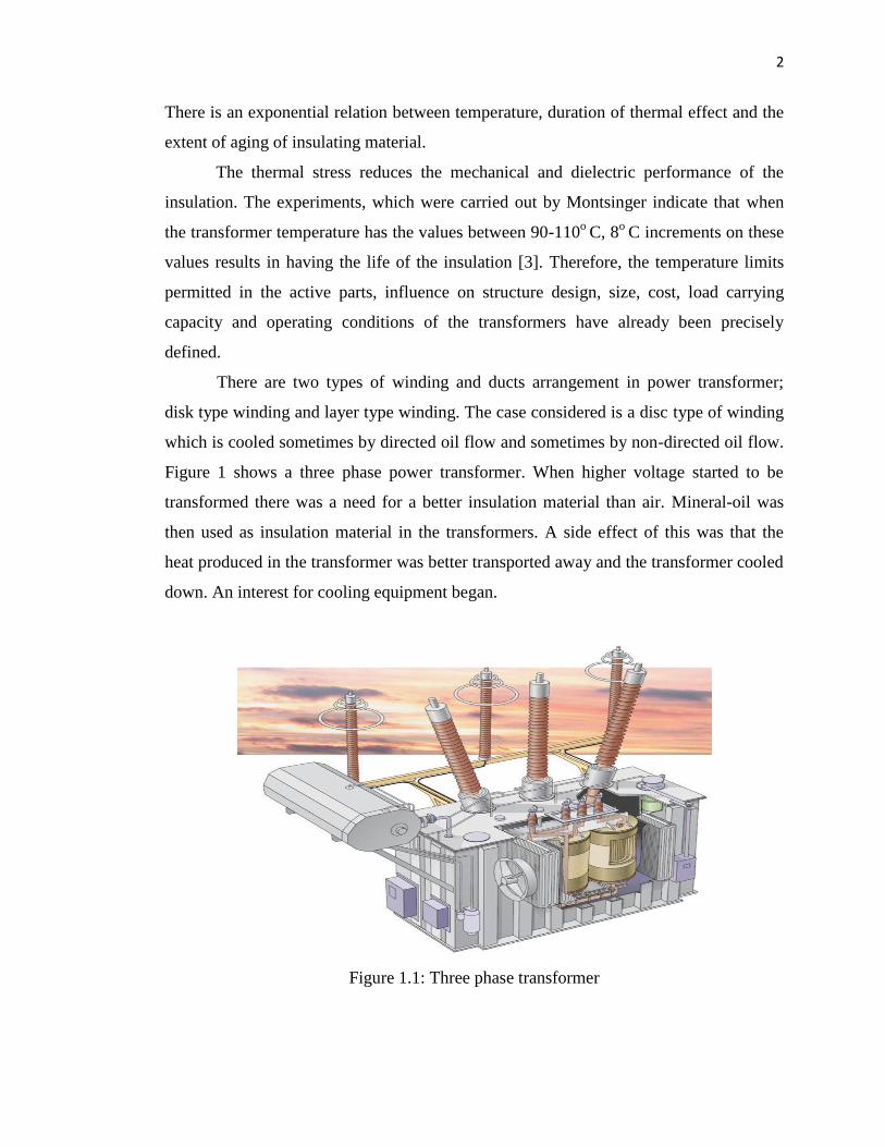
There are two types of winding and ducts arrangement in power transformer;
disk type winding and layer type winding. The case considered is a disc type of winding
which is cooled sometimes by directed oil flow and sometimes by non-directed oil flow.
Figure 1 shows a three phase power transformer. When higher voltage started to be
transformed there was a need for a better insulation material than air. Mineral-oil was
then used as insulation material in the transformers. A side effect of this was that the
heat produced in the transformer was better transported away and the transformer cooled
down. An interest for cooling equipment began.
Figure 1.1: Three phase transformer

3
1.2 Problem Statement
The no load losses and the load loss consist of I2R,all these losses cause heating in the
corresponding parts of transformer and this heat must be taken away to avoid high
temperature which will cause deterioration of insulation.
In liquid-immersed power transformers, the temperature of the winding is very
important in order to prolong the service life of the transformer. Knowing the
temperature distribution especially hot spot temperature at each point of transformer is
vital [6, 7, 8, 9, 10] to ensure safe operation during the period of service. The winding
made of copper can hold mechanical strength up to several hundred degrees Celsius
without deterioration and the transformer oil does not significantly degrade blow 140 C
o, however this is not case for the paper insulation. The paper insulation deterioration
rapidly if its temperature is more than 90 Co
[11].
Most of the transformers are using mineral oil as transformer insulating oil. The
insulating oil temperature depends on the winding temperature and is usually used to
indicate the operating conditions of the transformer [9]. The increase in temperature will
influence the insulating material and may cause aging. Depends to the insulating
material type, the transformer has a maximum limit of temperature rise [12].
There are several types of numerical protection relay designed to provide
protection for transformers. They are also used to calculate losses due to high
temperature generated inside the transformer. In this project, Matlab software is used to
predict the heat distribution in liquid-immersed transformers.
1.2 Objectives
The objectives of this project are as the following:
(i) To study the distribution of both the oil velocity flow and temperature inside coil
of transformer.

4
(ii) To develop a program using MATLAB, that can modulate the suitable
parameter that not exceeds maximum temperature rise in disk coil transformer.
(iii) To analyze the result of sensitivity study.
1.3 Project Scope
The scope of this study is designed base on the following considerations:
(i) Transformer parameter
The project will consider only three transformer parameters which are
different location of block washer for five disks, vertical duct size and
horizontal duct size.
This study focus on pressure drop, oil velocity and temperature value for five
disks.
Transformer cooling type for this study is oil directed air flow (ODAF).
(ii) Software
Develop a program to model and perform numerical calculation using Matlab
Software

CHAPTER 2
LITERATURE REVIEW
2.1 Introduction
This chapter presents literature reviews that focus on both fundamental theories and
modeling of transformer. This includes specification of power transformer, cooling
system, oil flow, and also MATLAB software.
2.2 Power Transformer
A power transformer is the electrical device which is used to change the voltage of AC
in power transmission system. Modern large and medium power transformers consist of
oil tank with oil filling in it, the cooling equipment on the tank wall and the active part
inside the tank. As the key part of a transformer, the active part consists of 2 main
components: the set of coils or windings (at least comprising a low voltage, high voltage
and a regulating winding) and the iron core, as figure 2.1 shows. For a step-up
transformer, the primary coil is low voltage (LV) input and the secondary coil is high
voltage (LV) output. The situation is opposite for a step-down transformer. The iron core

6
is the part inducing the varying magnitude flux. Nowadays, transformers play key roles
in long distance high-voltage power transmission.
Figure 2.1: Structures of disk winding transformer
The term power transformers used to refer to those transformers used between
the generator and the distribution circuits and these are usually rated at 500 kVA and
above. Power systems typically consist of a large number of generation locations,
distribution points, and interconnections within the system or with nearby systems, such
as a neighboring utility. The complexity of the system leads to a variety of transmission
and distribution voltages. Power transformers must be used at each of these points where
there is a transition between voltage levels.
Power transformers are selected based on the application, with the emphasis
toward custom design being more apparent the larger the unit. Power transformers are
available for step-up operation, primarily used at the generator and referred to as
generator step-up (GSU) transformers, and for step-down operation, mainly used to feed
distribution circuits. Power transformers are available as single-phase or three-phase
apparatus. The construction of a transformer depends upon the application. Transformers
intended for indoor use are primarily of the dry type but can also be liquid immersed.
For outdoor use, transformers are usually liquid immersed.
7
The normal life expectancy of a power transformer is generally assumed to be
about 30 years of service when operated within its rating. However, under certain
conditions, it may be overloaded and operated beyond its rating, with moderately
predictable “loss of life.” Situations that might involve operation beyond rating include
emergency rerouting of load or through-faults prior to clearing of the fault condition.
Power transformers have been loosely grouped into three market segments based on size
ranges [10, 13, 14]. These three segments are:
a) Small power transformers: 500 to 7500 kVA
b) Medium power transformers: 7500 to 100 MVA
c) Large power transformers: 100 MVA and above.
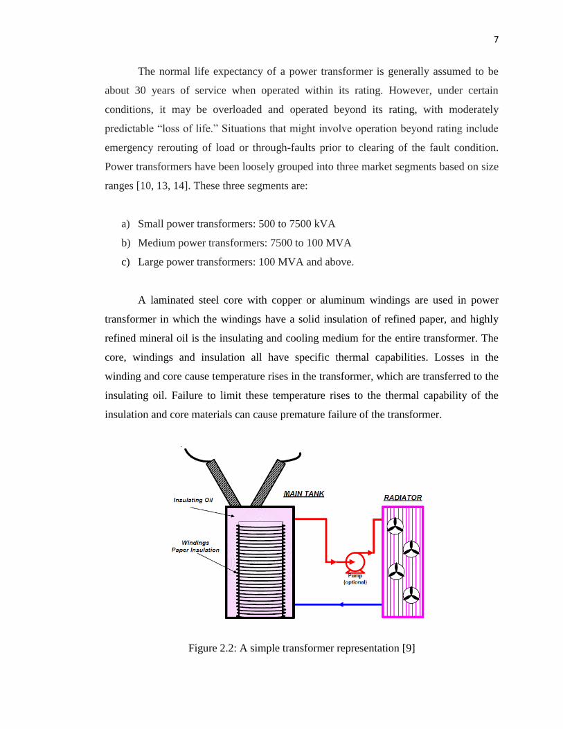
A laminated steel core with copper or aluminum windings are used in power
transformer in which the windings have a solid insulation of refined paper, and highly
refined mineral oil is the insulating and cooling medium for the entire transformer. The
core, windings and insulation all have specific thermal capabilities. Losses in the
winding and core cause temperature rises in the transformer, which are transferred to the
insulating oil. Failure to limit these temperature rises to the thermal capability of the
insulation and core materials can cause premature failure of the transformer.
Figure 2.2: A simple transformer representation [9]

8
2.2.1 Liquid-Filled of Transformer
Each of the transformers is constructed according to its application. Indoor transformer
intended to use dry type transformer but sometimes can be liquid-filled. But for outdoor
use, usually liquid-filled transformer will be chosen. Some of the dry type transformer
are not suitable for outdoor because the method of cooling system is by circulating air
through the coil and core assembly which is use either by force air flow (fan) or natural
convection.
This cooling method is suitable for low voltage – indoor transformer. At higher
voltage, oil is needed to insulate the winding due to the losses which are high through
the process of conduction, convection and radiation for effective winding cooling, the
moving oil must be able to contact with every conductor for maximum convection and
conduction of the conductor heat from the winding to the oil. In the other hand, direct oil
cooling is not effective for outdoor environment where it can make the windings dirt and
moisture.
A Comparison of Liquid-Filled and Dry Type Transformer Technologies written
by Tommy Nunn [7] of IEEE-IAS Cement Industry Committee evaluated the
comparison both types of the transformer. He stated that both type have pro and cont in
terms of loads, environment, purchase cost, safety, availability to operate, materials and
manufacturing process. In recent years, transformers technologies have improved the
insulation system, core material and computer design programs.
Another research has been done by Jerrery Wimmer, M. R. Tanner, Tommy
Nunn and Joel Kern on the specification Installation and operational impact of both
types in a marine environment [8]. They found that fiber glass winding will have
maximum operating size through 25000kVA and also application of vacuum
technologies increased the reliability on tap changing reduced the maintenance. Table
2.1 list some advantage and disadvantage of liquid-immersed transformer.

9
Table 2.1: Liquid-immersed transformer [9]
Advantage Disadvantage
Transformer oil is combustible
Needs oil regular checking filtration and
replacement of oil
Smaller size Costly and need high recurring expense
Lower cost Produce a little bit of danger
Greater overload capability Located away from the main building
2.2.2 Transformer Heating
In thermal modeling of power transformer, two significant sources of heating are
considered; no-load losses and load losses. Whenever the transformer is energized, no-
load losses will present which is made up of hysteresis and eddy loss in the transformer
core. Hysteresis loss is caused by the elementary magnets in the material aligning with
the alternating magnetic field. Eddy currents are induced in the core by the alternating
magnetic field.
Load losses consist of copper loss due to the winding resistance and stray load
loss due to eddy currents in other structural parts of the transformer. The copper loss
consists of both DC resistance loss, and winding eddy current loss. The amount of loss is
dependent on transformer load current, as well as oil temperature. DC resistance loss
will increase the increasing temperature but other load losses decrease with increasing
oil temperature [9].
Temperature in liquid-filled transformer can be decreased by transferring heat
from the core and windings to the insulating oil. Nature circulation of the coil will
transfer heat to the external radiators. The radiators are used to increase the cooling
surface area of the transformer. Sometimes, pumps are used to increase the oil flow and
at the same time radiators efficiency also increasing. For some large transformer (at

10
substation and power plan) required active cooling to remove the heat from the core and
windings and usually through circulating oil. Sometimes have two stage of cooling.
There are various cooling modes of transformer that established by IEEE and
IEC. IEEE has adopted the IEC designation [9]. The designations totally describe the
cooling method for the transformer and the cooling method impact the response of
insulating oil to overload condition. Table 2.2 lists the common transformer cooling
designations.
Table 2.2: Transformer cooling designations [9]
Old IEEE Cooling Designations IEC Equivalent
Self-cooled OA ONAN
Forced air cooled FA ONAF
Directed-flow forced liquid cooled FOA ODAF
Water cooled OW OFWF
Forced liquid and water cooled FOW OFWF
2.2.3 Impact Oil Temperature of Transformer
The temperature of insulating oil will increase if the transformer load is increases, so
loading the transformer above the nameplate rating can cause a risk to transformers life
[5]. According to the IEEE standard, temperature rise of the oil near to the top main tank
should not exceed 65º C.
These risks include reduced dielectric integrity due to gassing, reduced
mechanical strength and permanent deformation of structural components such as the
core and windings, or possible to damage auxiliary equipment such as tap changers,
bushings, or current transformers. If the insulation system follow the IEEE STD
C57.100 [52], it will get the acceptable thermal aging performance and at least can be
used up to 20.5 years (180 000 h). Standard temperature limits are defined in the IEEE

11
standard - Guide for Loading Mineral Oil-Immersed Power Transformers and list in the
Table 2.3.
Table 2.3: IEEE standard temperature rise
Standard temperature limits
Average windings temperature rise
Hot-spot temperature rise
Top liquid temperature rise
Maximum temperature limit
65º C
80º C
65º C
110º C
Above ambient
Above ambient
Above ambient
Absolute
The insulating transformer’s fluid must meet the same criteria similar to those
other high voltage equipment such as circuit breaker and capacitors. The criteria are:
i. The fluid must conduct heat but not electricity
ii. Must not be chemical reactive
iii. Must not be easily ionize that can allow are.
2.3 Review of Previous Research
Robert M. Del Vecchio and Pierre Feghali (1999) have modeled a thermal model of a
disk coil with directed oil flow. In this model each path segment, oil velocities and
temperature rises are computed. The oil Flow is assumed to be thermally driven. The
model includes temperature dependent oil viscosity, resistivity, oil density, and
temperature and velocity dependent heat transfer and friction coefficients a computer
code based on the analysis The code calculates temperatures of the coil disks and of the
oil in all the ducts as well as duct oil velocities[15].
GüvenKömürgöz İbrahim ÖzkolNurdanGüzelbeyoğlu (2001) in this study the
temperature distribution in the disk coil of transformer winding, there are series of
numerical experiments are conducted so as to develop a new thermal model for oil

12
immersed transformer windings. A line of eight-disc-coil has been modeled as a series
of heat producing sources in a vertical channel. The heat transfer equations for the model
in hand were solved by a semi numerical-analytical method to obtain temperature
distribution. Also, the results obtained are verified by ANSYS packet program [4].
Zoran R. Radakovic and Marko S. Sorgic (2010) they have introduced basics of
detailed thermal hydraulic model for thermal design of oil power transformers .The
paper presents the method for the calculation of temperatures inside oil power
transformers, and the transformer in more detail starting from the construction of a
transformer, physical parameters of applied materials, temperature of the outer cooling
medium, and distribution of power losses, and the calculation temperature distribution of
the winding, in each conductor of the oil, temperature in each cooling channel and in
each characteristic point, and in the core, on the surfaces and the hottest spots[16].
Table 2.4: Summary of technology development that done by other researcher
Author
Findings
Oil
Velocity Pressure
Flow
Rate
Temperature
Disk Oil Path Nodal
A.J. Oliver [5] √ √ √ √
A.Weinlader [17] √ √ √ √ √ √
E.P. Childs [18] √ √
F. Torriano [8] √ √ √
DelVecchio[
HYPERLINK \l
"RMD991" 12 ]
√ √ √ √ √ √
J.Zhang [19] √ √ √
J.Zhang [20] √ √ √ √
L. W. Pierce [21] √ √ √

13
2.4 Oil Guided and Non-Oil Guided Disk Windings
Oil guided and non-oil guided windings are proposed in disc windings transformers. In
the active part, as shown in Figure 2.1, between winding and core, LV windings and HV
windings, windings and outer casing, there are insulation board layers. Then, a closed
space can be formed for each layer of windings. Figure 2.3 shows the 2D cross sectional
area of one layer of disc windings. As Figure 2.3 at the left side shows, the guides are set
in vertical ducts every 6 disks are oil guides. The purpose of setting oil guides is to
improve the natural convection capability of the oil flow by avoiding the stagnation of
the oil inside ducts. Cold oil come in the windings from the bottom and go through the
vertical and horizontal ducts, the oil guides would change the oil flow direction and
make the global oil distribution even.
Figure 2.3: 2D cross-sectional images of disk windings
In reality and the real manufacturing process, considering some situation with
quite small windings radius as well as cost effective consideration, the non-guided disk
windings may be applied. Figure 2.3 at the right side shows the 2D cross-sectional
image of non-oil guided winding. It can be seen that the construction of non-oil guide

14
winding looks like a longer section of winding with oil guides. For non-oil guided
model, due to its large scale in the vertical length, the oil flow distribution as well as the
temperature distribution is expected to become complex [4, 5, 17].
2.5 Transformer Cooling System
The heat produced in a transformer must be dissipated to an external cooling medium in
order to keep the temperature in a specified limit. If transformer insulation is
experienced higher temperature than the allowed value for a long time, it will cause
rapid degradation of insulation and hence severely affect the transformer life.
In oil immersed transformer, the heat is transferred from the active parts (core,
winding and structural components) to the external cooling medium by the oil. The heat
from the active parts is transferred by the process of oil circulation. The process of
transferring heat from involves three different heat transfer mechanisms which are
conduction, convection and radiation [12]. The conduction process involves the heat
transfer between the solid parts, whereas the convection process involves the heat
transfer between a solid surface to a liquid or vice versa. The heat transfer by radiation is
between solid or liquid to the surrounding ambient temperature.
The most important heat transfer mechanism in an oil immersed transformer is
through the convection. The convection process occurs between transformer winding
and oil. It is always neglected in thermal calculation because of low surface temperature
and small area available on a transformer for radiation process to occur. Four common
types of cooling arrangement have been used in the industry and they will be explained
in more details. There are four common types of cooling arrangement have been used.

15
2.6 Cooling Arrangement
2.6.1 Oil Natural Air Natural (ONAN)
The simple and most common cooling type used in the practice is ONAN. ONAN refers
to Oil Natural Air Natural. The ONAN cooling is achieved when the oil flow through
the transformer winding is driven by pressure difference between the tank oil and the
cooler oil. This pressure difference is due to a temperature difference between the oil
temperature in the tank and the oil temperature in the radiators. This natural circulation
of oil sometimes has been referred as a “thermo siphon” effect. The ONAN design is
shown in Figure 2.4.and arrows in the figure show the oil flow direction in the
transformer.
The term siphon effect occurs when the heat generated in transformer core and
winding are dissipated to surrounding oil mainly through the convection process. The
density of the oil is inversely proportional to the temperature and is proportional to the
pressure and height. As the oil temperature increases, its density reduces. The oil
becomes light and due to buoyancy effect it moves upwards towards the top of the tank.
Its place is taken by the cool oil from bottom which has a higher density. As the oil
enters the cooler, the heat is dissipated along colder surfaces of the cooler, at the same
time oil increases its density. The oil then flows downwards through the cooler and
enters the bottom of transformer tank from the inlet thus the continuous oil circulation
occurs.
The oil velocity in this natural circulation is relatively slow throughout the
transformer and radiators. For this reason, ONAN transformers have large temperature
difference between top oil and the bottom oil. They also have relatively large
temperature difference between the winding temperature and the oil temperature.
16
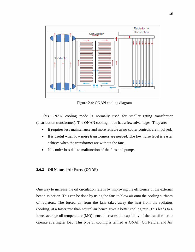
Figure 2.4: ONAN cooling diagram
This ONAN cooling mode is normally used for smaller rating transformer
(distribution transformer). The ONAN cooling mode has a few advantages. They are:
It requires less maintenance and more reliable as no cooler controls are involved.
It is useful when low noise transformers are needed. The low noise level is easier
achieve when the transformer are without the fans.
No cooler loss due to malfunction of the fans and pumps.
2.6.2 Oil Natural Air Force (ONAF)
One way to increase the oil circulation rate is by improving the efficiency of the external
heat dissipation. This can be done by using the fans to blow air onto the cooling surfaces
of radiators. The forced air from the fans takes away the heat from the radiators
(cooling) at a faster rate than natural air hence gives a better cooling rate. This leads to a
lower average oil temperature (MO) hence increases the capability of the transformer to
operate at a higher load. This type of cooling is termed as ONAF (Oil Natural and Air

17
Forced) as shown in figure 2.5. The introduction of the fans to the radiators improves the
cooling characteristics of the radiators thereby reducing the number of radiators required
to achieve the same amount of cooling. This also leads to smaller overall dimensions of
the transformer/cooling design.
Figure 2.5: ONAF cooling diagram
In the ONAF cooling mode the oil circulates through the core and winding as the
same as in the ONAN cooling mode. The flow rate inside the winding under ONAN and
ONAF cooling arrangement is controlled by the themosiphon effect. Normally this flow
rate is relatively low. Because of this, the heat dissipating of oil is low. The heat capacity
can be expressed as
QUOTE (2.1)
Where Q is heat flow in W, m is mass flow rate in Kg/s, Cp is specific heat in J/
(Kg Co), and temperature Tout (top oil temperature) and Tin (bottom oil temperature) are
in Co.
18
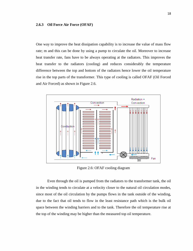
2.6.3 Oil Force Air Force (OFAF)
One way to improve the heat dissipation capability is to increase the value of mass flow
rate; m and this can be done by using a pump to circulate the oil. Moreover to increase
heat transfer rate, fans have to be always operating at the radiators. This improves the
heat transfer to the radiators (cooling) and reduces considerably the temperature
difference between the top and bottom of the radiators hence lower the oil temperature
rise in the top parts of the transformer. This type of cooling is called OFAF (Oil Forced
and Air Forced) as shown in Figure 2.6.
Figure 2.6: OFAF cooling diagram
Even through the oil is pumped from the radiators to the transformer tank, the oil
in the winding tends to circulate at a velocity closer to the natural oil circulation modes,
since most of the oil circulation by the pumps flows in the tank outside of the winding,
due to the fact that oil tends to flow in the least resistance path which is the bulk oil
space between the winding barriers and to the tank. Therefore the oil temperature rise at
the top of the winding may be higher than the measured top oil temperature.

19
2.6.4 Oil Direct Air Force (ODAF)
Figure 2.7 shows a group of conductors surrounded by vertical and horizontal cooling
ducts. The heat generated in each conductor must be transferred to the oil to keep the
temperature within the limits. The heat flow in the horizontal direction from a central
conductor is limited by the similar temperature conductors on either side of it. Therefore
the heat can transferred via vertical directions.
Figure 2.7: Cross section of a disc or helical winding showing heat flow paths
Naturally the oil tends to rise when it become hot. The vertical ducts provide a
natural circulation path for this hot oil. This causes the oil flow through the horizontal
ducts is much less than that in the vertical ducts and hence poor heat transfer between
the conductors and the oil in the horizontal ducts. However the disks depend on the
horizontal oil ducts for their cooling. This is the reason why directing the oil through the
winding using block washer to occasionally block the vertical ducts is so important in
achieving effective heat transfers from the conductors. The oil flow between the discs
for a typical directed oil design is shown in Figure 2.8.

20
Figure 2.8: Oil flow in a directed flow winding
The transformer with directed forced cooling is called ODAF (Oil Directed Air
Forced). A typical arrangement is detailed in Figure 2.8. Where the pumps are used to
move the oil into the transformer and block washer are used to direct the oil flows inside
the winding. The OD design will result in lower winding gradients than the ON and OF.
It also reduces the top oil temperature rise of the winding and therefore the hotspot rise
is much reduced compared to the ON and OF cooling mode.
As seen in Figure 2.9, block washer are often added alternately on the inner and
outer diameters of the winding. The block washer will direct the oil to flow in horizontal
ducts between the discs in order to improve conductor-oil heat transfer.

21
Figure 2.9: ODAF cooling diagram

CHAPTER 3
METHODOLOGY
3.1 Introduction
Methodology includes the following concepts as they relate to a particular discipline of
field of inquiry: collection of theories, concept or ideas; comparative study of different
approached; and critique of the individual methods. Methodology refers to more than a
simple set of methods; rather it refers to the rationale and the philosophical assumptions
that underlie a particular study. Proper process guidance will help to monitor and
troubleshoot any problem occurred in the middle of the process and also to make sure
the project is successfully.
3.2 Project Methodology
This project begins with collecting information regarding the technical issue in order to
develop a thermal model of a disk coil using MATLAB. Figure 3.1 illustrate the flow
chart that will be used in modeling thermal model of a disk coil.

23
NO
YES
NO
SUCCESS
Figure 3.1: Flow chart in modeling thermal disk oil
Start
Collecting all the relevant information
Analyze the information
Enough
info?
Working planning & built the program
Modeling
Testing
the model
Adjust the program
Thesis Writing
End
Methodology
24
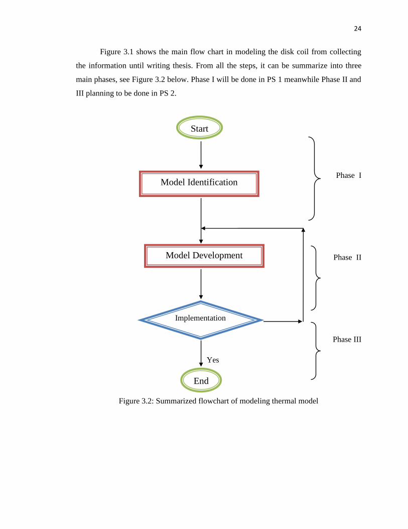
Figure 3.1 shows the main flow chart in modeling the disk coil from collecting
the information until writing thesis. From all the steps, it can be summarize into three
main phases, see Figure 3.2 below. Phase I will be done in PS 1 meanwhile Phase II and
III planning to be done in PS 2.
Phase I
Phase II
Phase III
Yes
Figure 3.2: Summarized flowchart of modeling thermal model
Start
Model Identification
Model Development
Implementation
End

68
REFFERENCES
[1] Susa D., Lehtonen M., and Nordman H., (2005)" Dynamic Thermal Modeling
of Power Transformers", IEEE Transactions on Power Delivery, Vol. 20, Iss. 1,
January 2005, pp. 197 – 204.
[2] MohadTaufiqIshak.,"Simulation Study on Influencing Parameters of Thermal
Ageing for Transformer Lifetime Prediction", 17 DEC2009.
[3] KIRIS., ÖZKOL “Determination of temperature distribution in the disk –type
coil of transformer windings via numerical –analytical methods” ,Journal of
Electrical & Electronics Engineering, Vol 2, No 2 (2002).
[4] Kömürgöz, G., Özkol, Ý.,Güzelbeyoðlu, N., “ Temperature Distribution in the
Disc-Type Coil of Transformer Winding”, ELECO’(2001) , Second
International Conference on Electrical and Electronics.
[5] A. J. Oliver, "Estimation of transformer winding temperatures and coolant
flows using a general network method," 1980.
[6] S.H. Digby H. J. Sim, "Transformer design for dual voltage application," in
IEEE, Rural Electrical power Conference, 2002.
[7] A. Bulucea, L. Perescu M. C. Popescu, "Improved transformer thermal model,"
in WSEAS Transaction on Heat and Mass Transfer, 2009, pp. Vol. 4, No. 4.
[8] M. Chaaban, P.Picher F. Torriano, "Numerical study of parameters affecting
the temperature distribution in a disc type winding," 2010
[9] L. Michael. Giordano Rich Hunt, "Thermal overload protection of power
transformers – operating theory and practical experience," , Atlanta, Georgia,
2005
[10] Robert M. Del Vecchio [et al.], “Transformer design principles with
application to core-form power transformer”: CRC Press, 2010.

69
[11] M.J. Heathcote, J&P Transformer Book (1998). 12th ed. London, Reed
Education and Professional Publishing Ltd, 1998.
[12] T. Nuun, "A comparison of liquid-filled and dry-type transformers,”, 2000.
[13] M. Lehtonen, H. Nordman D. Susa, "Dynamic thermal modeling of power
transformers," in IEEE, Transaction on Power Delivery, 2005, pp. Vol. 20,
No.1
[14] James H. Harlow, “Electric Power Transformer Engineering,”, CRC Press I Llc
, 2004.
[15] R. M. Del Vecchio and P. Feghali, "Thermal model of a disk coil with directed
oil flow," in IEEE, Transmission and Distribution Conference, 1999, pp. 914-
919.
[16] M. S. Sorgic Z. R. Radakovic, "Basics of detailed thermal-hydraulic model for
thermal design of oil power transformers," , 2010.
[17] R.Hosseini, M.Nourolahi&G.B.Gharehpetian, 2008. Determination of OD
cooling system parameters based on thermal modeling of power transformer
winding. Simulation modelling Practice and Theory, pp. 585-596
[18] M. Chaaban, P.Picher F. Torriano, “Numerical study of parameters affecting
the temperature distribution in a disc type winding,” 2010.
[19] W. Wu, S. Tenbohlen, Z. Wang A. Weinlader, “Prediction of the oil flow
distribution in oil-immersed transformer windings by network modeling and
computational fluid dynamic,” vol. 6, no. 2, 2011.
[20] X.Li M. Vance, J. Zhang, “Experiments and modeling of heat transfer in oil
transformer winding with zigzag cooling ducts,”, Canada, 2007.
[21] X. Li, J. Zhang, “Coolant flow distribution and pressure loss in ONAN
transformer windings – Part I: Theory and model development,” vol.19, no.
No. 1, 2004.
[22] S.H. Digby H. J. Sim, “Transformer design for dual voltage application,” in
IEEE, Rural Electric Power Conference, 2002.
[23] A. Bulecea, L. Perescu M.C. Popescu, “Improved transformer thermal model,”
in WSEAS Transaction on Heat and Mass Transfer, 2009, pp. Vol. 4, No. 4.
70
[24] B. Poulin [et all], Transformer design principles with application to core-form
power transformer : CRC Press, 2010.
[25] M.R Tanner, T.Nuun, J.Kern J. Wimmer, “Dry type vs. liquid immersed
transformer: Specification installation and operational impact in a marine
environment, “ in Petroleum and Chemical Industry Conference (PCIC), 2011
Record of Conference Papers Industry Application Society 58th Annual IEEE,
2011. pp. 1-8.
[26] N. C. Chereches, J. Padet N. El. Wakil, “Numerical study of heat transfer and
fluid flow in a power transformer,” 2005.
[27] “IEEE Standard for General Requirement for Liquid-immersed Distribution,
Power, and Regulating Transformer,” New York, 2010.
[28] S.V. Kulkani and S.A. Khaparde, Transformer Engineering (2004): Design and
Practice. New York,Marcel Dekker,Inc,2004.