Embed Size (px)
Citation preview
Sensorless Regulation of a Brushless DC Motor with a C164CM
Page 1/31
V0.
It includes the protocol specification (Host – Microcontroller – Demonstrator) and the prototypedefinition of the basic functions.
Application Note, V 1.0, Jan. 2001
Sensorless Regulation of aBrushless DC Motor with aC164CM ( Voltage Detection Mode )
Authors: R. Weiss & T. Kattwinkel
16 – Bit CMOS Microcontroller Product
Microcontrollers
AP1676
Application Note, V 1.0, July 2001
N e v e r s t o p t h i n k i n g .

Sensorless Regulation of a Brushless DC Motor with a C164CM
Page 2/31
Revision History
Revision Modifications Date Modified by
Edition 2001-07
Published by Infineon Technologies AG 81726 München, Germany
© Infineon Technologies AG 2006. All Rights Reserved.
LEGAL DISCLAIMER THE INFORMATION GIVEN IN THIS APPLICATION NOTE IS GIVEN AS A HINT FOR THE IMPLEMENTATION OF THE INFINEON TECHNOLOGIES COMPONENT ONLY AND SHALL NOT BE REGARDED AS ANY DESCRIPTION OR WARRANTY OF A CERTAIN FUNCTIONALITY, CONDITION OR QUALITY OF THE INFINEON TECHNOLOGIES COMPONENT. THE RECIPIENT OF THIS APPLICATION NOTE MUST VERIFY ANY FUNCTION DESCRIBED HEREIN IN THE REAL APPLICATION. INFINEON TECHNOLOGIES HEREBY DISCLAIMS ANY AND ALL WARRANTIES AND LIABILITIES OF ANY KIND (INCLUDING WITHOUT LIMITATION WARRANTIES OF NON-INFRINGEMENT OF INTELLECTUAL PROPERTY RIGHTS OF ANY THIRD PARTY) WITH RESPECT TO ANY AND ALL INFORMATION GIVEN IN THIS APPLICATION NOTE.
Information For further information on technology, delivery terms and conditions and prices please contact your nearest Infineon Technologies Office (www.infineon.com).
Warnings
Due to technical requirements components may contain dangerous substances. For information on the types in question please contact your nearest Infineon Technologies Office. Infineon Technologies Components may only be used in life-support devices or systems with the express written approval of Infineon Technologies, if a failure of such components can reasonably be expected to cause the failure of that life-support device or system, or to affect the safety or effectiveness of that device or system. Life support devices or systems are intended to be implanted in the human body, or to support and/or maintain and sustain and/or protect human life. If they fail, it is reasonable to assume that the health of the user or other persons may be endangered.

Sensorless Regulation of a Brushless DC Motor with a C164CM
Page 3/31
Contents1 INTRODUCTION........................................................................................................................................................ 5
1.1 WHY USE BRUSHLESS DC MOTORS (ADVANTAGES/DISADVANTAGES)?.............................................................5
1.2 FUNCTIONAL PRINCIPLE OF A BRUSHLESS DC MOTOR..........................................................................................5
1.3 BRUSHLESS DC MOTOR WITH HALL SENSORS........................................................................................................6
1.4 BRUSHLESS DC MOTOR WITHOUT HALL SENSORS................................................................................................6
2 OPERATION OF A BRUSHLESS DC MOTOR................................................................................................ 8
2.1 VISUALIZATION OF THE ROTATION INCLUDING APPROPRIATE SWITCHES OF A 3-PHASE BRUSHLESS DCMOTOR (0° MECHANICAL TO 180° MECHANICAL)............................................................................................................8
2.1.1 Position ‘ 0° ’................................................................................................................................................... 9
2.1.2 Position ‘ 30° ’ ..............................................................................................................................................10
2.1.3 Position ‘ 60° ’ ..............................................................................................................................................11
2.1.4 Position ‘ 90° ’ ..............................................................................................................................................12
2.1.5 Position ‘ 120° ’ ............................................................................................................................................13
2.1.6 Position ‘ 150° ’ ............................................................................................................................................14
2.1.7 Position ‘ 180° ’ ............................................................................................................................................15
2.2 SENSORS.....................................................................................................................................................................16
2.2.1 Hall sensor output signal ............................................................................................................................16
2.3 SYSTEM DESCRIPTION..............................................................................................................................................16
2.3.1 Block diagram of block commutation using Hall sensors.....................................................................16
2.3.2 Block diagram of block commutation without sensors ..........................................................................17
3 BLOCK COMMUTATION MODE WITH BACK-EMF DETECTION...................................................19
3.1 GENERAL....................................................................................................................................................................19
3.1.1 Back–EMF sensing ......................................................................................................................................19
3.2 REQUIRED PERIPHERALS..........................................................................................................................................22
3.2.1 CAPCOM6.....................................................................................................................................................22
3.2.2 ADC.................................................................................................................................................................23
4 IMPLEMENTATION ...............................................................................................................................................24
Sensorless Regulation of a Brushless DC Motor with a C164CM
Page 4/31
4.1 FUNCTIONAL DESCRIPTION .....................................................................................................................................24
4.1.1 General description .....................................................................................................................................24
4.1.2 Management of commutation, demagnetization and zero cross detection.........................................25
4.2 IMPLEMENTATION OF THE SOFTWARE ...................................................................................................................25
4.2.1 Initialization..................................................................................................................................................25
4.2.2 State machine................................................................................................................................................26
4.2.3 Interrupt routines .........................................................................................................................................26
4.3 PERFORMANCE ANALYSIS........................................................................................................................................28
4.3.1 Hardware requirements ..............................................................................................................................28
4.3.2 CPU load .......................................................................................................................................................28
5 CONCLUSION............................................................................................................................................................30
6 ABBREVIATIONS ....................................................................................................................................................31
Sensorless Regulation of a Brushless DC Motor with a C164CM
Page 5/31
1 Introduction
1.1 Why use brushless DC motors (advantages/disadvantages)?
Brushless DC motors are synchronous motors suitable for use as a simple means of controllingpermanent drives (e.g. ABS pumps, EHPS pumps, fuel pumps or cooling fans). This type of 3-, 4- or5-phase brushless DC motor will increasingly replace brushed DC motors. Brushed DC motors requiremaintenance, e.g. to service coal brushes and commutator. Another major problem with a brushed DCmachine is the possibility of brush burnout in the event of an overload or stall condition.
One of the main advantages of brushless DC motors is their robustness against obsolescence (due tothe absence of brushes), and another major benefit is the high efficiency and high torque of abrushless DC motor.
A disadvantage of this type of motor is that the rotor position is usually determined by three Hallsensors (in the case of three phases), which are expensive and require signal conditioning, and thispositioning in the production process has to be done very precisely to assure proper operation.
1.2 Functional principle of a brushless DC motor
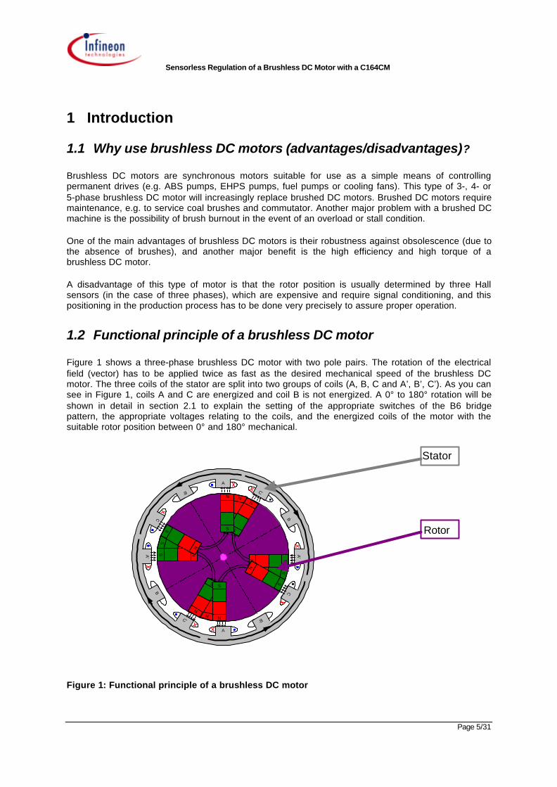
Figure 1 shows a three-phase brushless DC motor with two pole pairs. The rotation of the electricalfield (vector) has to be applied twice as fast as the desired mechanical speed of the brushless DCmotor. The three coils of the stator are split into two groups of coils (A, B, C and A’, B’, C’). As you cansee in Figure 1, coils A and C are energized and coil B is not energized. A 0° to 180° rotation will beshown in detail in section 2.1 to explain the setting of the appropriate switches of the B6 bridgepattern, the appropriate voltages relating to the coils, and the energized coils of the motor with thesuitable rotor position between 0° and 180° mechanical.
Figure 1: Functional principle of a brushless DC motor
A
A
B
B
B'
B'C'
C'
C
C
A'
A'
S
NN
S
N
S
S
NN
S
N
S
N
S
N S
N
S
N
S
NS
N
S
Stator
Rotor
Sensorless Regulation of a Brushless DC Motor with a C164CM
Page 6/31
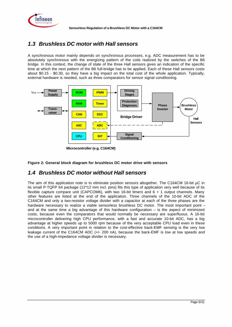
1.3 Brushless DC motor with Hall sensors
A synchronous motor mainly depends on synchronous processes, e.g. ADC measurement has to beabsolutely synchronous with the energizing pattern of the coils realized by the switches of the B6bridge. In this context, the change of state of the three Hall sensors gives an indication of the specifictime at which the next pattern of the B6 full-bridge has to be applied. Each of these Hall sensors costsabout $0.15 - $0.30, so they have a big impact on the total cost of the whole application. Typically,external hardware is needed, such as three comparators for sensor signal conditioning.
Vbat
Host
ROM
ASC
SSCCAN
TimerRAM
PWM
ADC
CPU
PowerSupply
Trans-ceiver
Microcontroller (e.g. C164CM)
Bridge Driver
SignalConditioning
DrivingStages
ProtectionDiagnoses Phase
InverterBrushless
Motor
HallSensors
INT
Figure 2: General block diagram for brushless DC motor drive with sensors
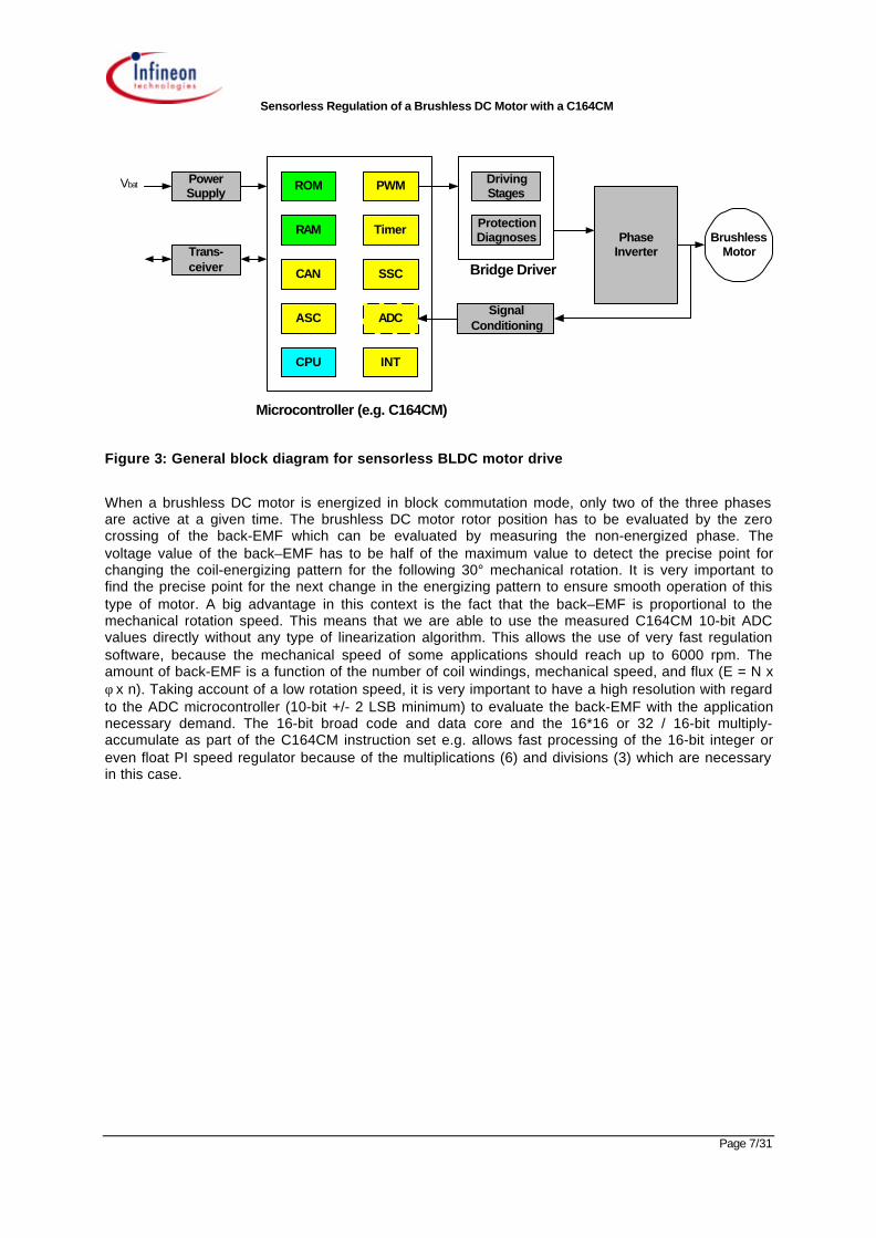
1.4 Brushless DC motor without Hall sensors
The aim of this application note is to eliminate position sensors altogether. The C164CM 16-bit µC inits small P-TQFP 64 package (12*12 mm incl. pins) fits this type of application very well because of itsflexible capture compare unit (CAPCOM6), with two 16-bit timers and 6 + 1 output channels. Manyother features are listed at the end of the application. Three channels of the 10-bit ADC of theC164CM and only a two-resistor voltage divider with a capacitor at each of the three phases are thehardware necessary to realize a viable sensorless brushless DC motor. The most important point –and at the same time a big advantage of this hardware configuration – is the aspect of minimizedcosts, because even the comparators that would normally be necessary are superfluous. A 16-bitmicrocontroller delivering high CPU performance, with a fast and accurate 10-bit ADC, has a bigadvantage at higher speeds up to 5000 rpm because of the very acceptable CPU load even in theseconditions. A very important point in relation to the cost-effective back-EMF sensing is the very lowleakage current of the C164CM ADC (+/- 200 nA), because the back-EMF is low at low speeds andthe use of a high-impedance voltage divider is necessary.
Sensorless Regulation of a Brushless DC Motor with a C164CM
Page 7/31
Vbat
Host
ROM
ASC
SSCCAN
TimerRAM
PWM
ADC
CPU
PowerSupply
Trans-ceiver
Microcontroller (e.g. C164CM)
Bridge Driver
SignalConditioning
DrivingStages
ProtectionDiagnoses Phase
InverterBrushless
Motor
INT
Figure 3: General block diagram for sensorless BLDC motor drive
When a brushless DC motor is energized in block commutation mode, only two of the three phasesare active at a given time. The brushless DC motor rotor position has to be evaluated by the zerocrossing of the back-EMF which can be evaluated by measuring the non-energized phase. Thevoltage value of the back–EMF has to be half of the maximum value to detect the precise point forchanging the coil-energizing pattern for the following 30° mechanical rotation. It is very important tofind the precise point for the next change in the energizing pattern to ensure smooth operation of thistype of motor. A big advantage in this context is the fact that the back–EMF is proportional to themechanical rotation speed. This means that we are able to use the measured C164CM 10-bit ADCvalues directly without any type of linearization algorithm. This allows the use of very fast regulationsoftware, because the mechanical speed of some applications should reach up to 6000 rpm. Theamount of back-EMF is a function of the number of coil windings, mechanical speed, and flux (E = N xφ x n). Taking account of a low rotation speed, it is very important to have a high resolution with regardto the ADC microcontroller (10-bit +/- 2 LSB minimum) to evaluate the back-EMF with the applicationnecessary demand. The 16-bit broad code and data core and the 16*16 or 32 / 16-bit multiply-accumulate as part of the C164CM instruction set e.g. allows fast processing of the 16-bit integer oreven float PI speed regulator because of the multiplications (6) and divisions (3) which are necessaryin this case.
Sensorless Regulation of a Brushless DC Motor with a C164CM
Page 8/31
2 Operation of a brushless DC motor2.1 Visualization of the rotation including appropriate switches of a
3-phase brushless DC motor (0° mechanical to 180°mechanical)
Only two of the three phases are energized in each state of the B6 full-bridge. The non-energizedphase can therefore be used to detect the zero crossing of the back-EMF as explained later (cf. theblack arrow in the voltage diagram shown in Figures 5, 7, 9, 11, 13, 15, 17). The following explanationwill show you the turning of a two pole-pair brushless DC motor as a function of the state of theappropriate switches shown in Figures 4, 6, 8, 10, 12, 14, 16. In fact, driving a two pole-pair motormeans that the rotation speed of the electrical field has to be double the speed of the desiredmechanical rotation speed (Ω = ω / p, where Ω is the mechanical rotation speed, ω the rotationfrequency of the electrical field and p is the number of pole pairs).
Sensorless Regulation of a Brushless DC Motor with a C164CM
Page 9/31
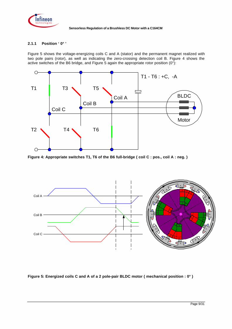
2.1.1 Position ‘ 0° ’
Figure 5 shows the voltage-energizing coils C and A (stator) and the permanent magnet realized withtwo pole pairs (rotor), as well as indicating the zero-crossing detection coil B. Figure 4 shows theactive switches of the B6 bridge, and Figure 5 again the appropriate rotor position (0°):
BLDC
Motor
Coil A
Coil CCoil B
T1 T3 T5
T2 T4 T6
T1 - T6 : +C, -A
Figure 4: Appropriate switches T1, T6 of the B6 full-bridge ( coil C : pos., coil A : neg. )
Figure 5: Energized coils C and A of a 2 pole-pair BLDC motor ( mechanical position : 0° )
A'
A'
A
A
B
B
B'
B'C'
C'
C
C
S
NN
S
N
S
S
NN
S
N
S
N
S
NS
N
S
N
S
N S
N
S
Coil A
Coil B
Coil C
Sensorless Regulation of a Brushless DC Motor with a C164CM
Page 10/31
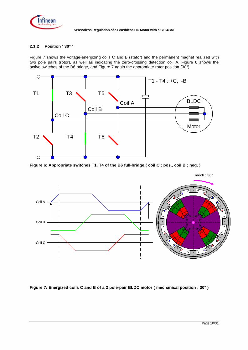
2.1.2 Position ‘ 30° ’
Figure 7 shows the voltage-energizing coils C and B (stator) and the permanent magnet realized withtwo pole pairs (rotor), as well as indicating the zero-crossing detection coil A. Figure 6 shows theactive switches of the B6 bridge, and Figure 7 again the appropriate rotor position (30°):
BLDC
Motor
Coil A
Coil CCoil B
T1 T3 T5
T2 T4 T6
T1 - T4 : +C, -B
Figure 6: Appropriate switches T1, T4 of the B6 full-bridge ( coil C : pos., coil B : neg. )
Figure 7: Energized coils C and B of a 2 pole-pair BLDC motor ( mechanical position : 30° )
C'
C'
C
C
A
A
A'
A'
B
B
B'
B'
S
N
N
S
N
S
S
N
N
S
N
S N
S
N
S
N
S
N
S
N
S
N
S
Coil A
Coil B
Coil C
mech : 30°

Sensorless Regulation of a Brushless DC Motor with a C164CM
Page 11/31
2.1.3 Position ‘ 60° ’
Figure 9 shows the voltage-energizing coils C and B (stator) and the permanent magnet realized withtwo pole pairs (rotor), as well as indicating the zero-crossing detection coil C. Figure 8 shows theactive switches of the B6 bridge, and Figure 9 again the appropriate rotor position (60°):
BLDC
Motor
Coil A
Coil CCoil B
T1 T3 T5
T2 T4 T6
T5 - T4 : +A, -B
Figure 8: Appropriate switches T4, T5 of the B6 full-bridge ( coil A : pos., coil B : neg. )
Figure 9: Energized coils A and B of a 2 pole-pair BLDC motor ( mechanical position : 60° )
B
B
B'
B'C'
C'
A'
A'
C
C
A
A
S
NNS
N
S
S
NN S
N
S
N
S
N
S
N
S
N
S
N
S
N
S
Coil A
Coil B
Coil C
mech : 60°
Sensorless Regulation of a Brushless DC Motor with a C164CM
Page 12/31
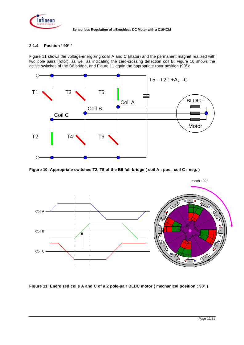
2.1.4 Position ‘ 90° ’
Figure 11 shows the voltage-energizing coils A and C (stator) and the permanent magnet realized withtwo pole pairs (rotor), as well as indicating the zero-crossing detection coil B. Figure 10 shows theactive switches of the B6 bridge, and Figure 11 again the appropriate rotor position (90°):
BLDC -
Motor
Coil A
Coil CCoil B
T1 T3 T5
T2 T4 T6
T5 - T2 : +A, -C
Figure 10: Appropriate switches T2, T5 of the B6 full-bridge ( coil A : pos., coil C : neg. )
Figure 11: Energized coils A and C of a 2 pole-pair BLDC motor ( mechanical position : 90° )
A'
A'
A
A
B
B
B'
B'C'
C'
C
C
S
NN
S
NS
S
NN
S
N S
N
S
N
S
N
S
N
S
N
S
N
S
Coil A
Coil B
Coil C
mech : 90°
Sensorless Regulation of a Brushless DC Motor with a C164CM
Page 13/31
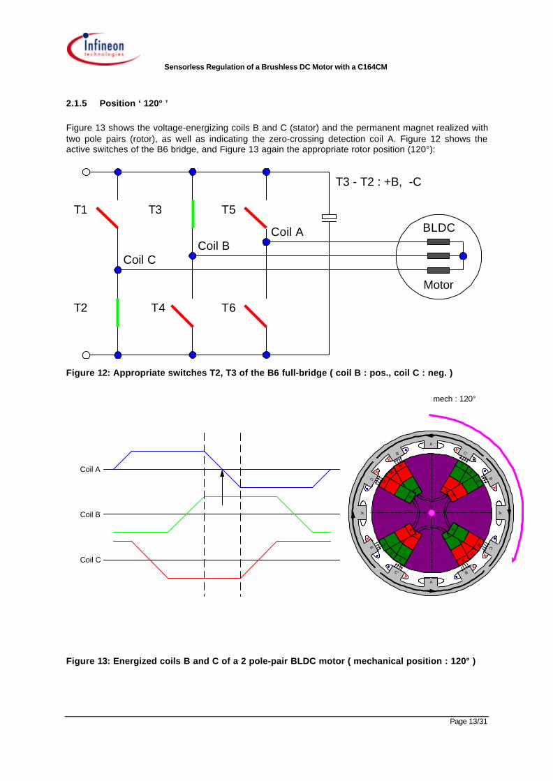
2.1.5 Position ‘ 120° ’
Figure 13 shows the voltage-energizing coils B and C (stator) and the permanent magnet realized withtwo pole pairs (rotor), as well as indicating the zero-crossing detection coil A. Figure 12 shows theactive switches of the B6 bridge, and Figure 13 again the appropriate rotor position (120°):
BLDC
Motor
Coil A
Coil CCoil B
T1 T3 T5
T2 T4 T6
T3 - T2 : +B, -C
Figure 12: Appropriate switches T2, T3 of the B6 full-bridge ( coil B : pos., coil C : neg. )
Figure 13: Energized coils B and C of a 2 pole-pair BLDC motor ( mechanical position : 120° )
C'
C'
C
C
A
A
A'
A'
B
B
B'
B'
S
N
N
S
N
S
S
N
N
S
N
S
N
S
N
S
N
S
N
S
N
S
N
S
Coil A
Coil B
Coil C
mech : 120°
Sensorless Regulation of a Brushless DC Motor with a C164CM
Page 14/31
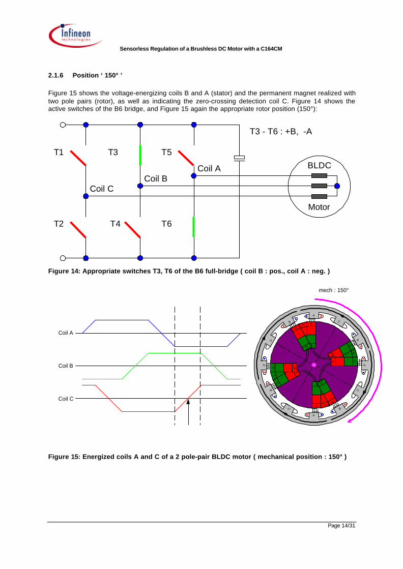
2.1.6 Position ‘ 150° ’
Figure 15 shows the voltage-energizing coils B and A (stator) and the permanent magnet realized withtwo pole pairs (rotor), as well as indicating the zero-crossing detection coil C. Figure 14 shows theactive switches of the B6 bridge, and Figure 15 again the appropriate rotor position (150°):
BLDC
Motor
Coil A
Coil CCoil B
T1 T3 T5
T2 T4 T6
T3 - T6 : +B, -A
Figure 14: Appropriate switches T3, T6 of the B6 full-bridge ( coil B : pos., coil A : neg. )
Figure 15: Energized coils A and C of a 2 pole-pair BLDC motor ( mechanical position : 150° )
B
B
B'
B'C'
C'
A'
A'
C
C
A
A
S
NN
S
N
S
S
N N
S
N
S
N
S
N
S
NS
N
S
N
S
N S
Coil A
Coil B
Coil C
mech : 150°
Sensorless Regulation of a Brushless DC Motor with a C164CM
Page 15/31
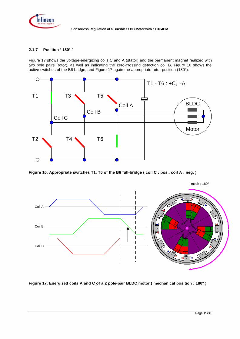
2.1.7 Position ‘ 180° ’
Figure 17 shows the voltage-energizing coils C and A (stator) and the permanent magnet realized withtwo pole pairs (rotor), as well as indicating the zero-crossing detection coil B. Figure 16 shows theactive switches of the B6 bridge, and Figure 17 again the appropriate rotor position (180°):
BLDC
Motor
Coil A
Coil CCoil B
T1 T3 T5
T2 T4 T6
T1 - T6 : +C, -A
Figure 16: Appropriate switches T1, T6 of the B6 full-bridge ( coil C : pos., coil A : neg. )
Figure 17: Energized coils A and C of a 2 pole-pair BLDC motor ( mechanical position : 180° )
A'
A'
A
A
B
B
B'
B'C'
C'
C
C
S
NN
S
N
S
S
NN
S
N
S
N
S
NS
N
S
N
S
N S
N
SCoil A
Coil B
Coil C
mech : 180°
Sensorless Regulation of a Brushless DC Motor with a C164CM
Page 16/31
2.2 Sensors
The BLDC motor is a synchronous motor and so the rotor position has to be known in order togenerate the appropriate field.
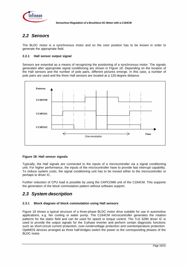
2.2.1 Hall sensor output signal
Sensors are essential as a means of recognizing the positioning of a synchronous motor. The signalsgenerated after appropriate signal conditioning are shown in Figure 18. Depending on the location ofthe Hall sensors and the number of pole pairs, different pictures emerge. In this case, a number ofpole pairs are used and the three Hall sensors are located at a 120-degree distance.
One revolutionTime
Patterns
CC6POS2
CC6POS0
CC6POS1
Figure 18: Hall sensor signals
Typically, the Hall signals are connected to the inputs of a microcontroller via a signal conditioningunit. For higher performance, the inputs of the microcontroller have to provide fast interrupt capability.To reduce system costs, the signal conditioning unit has to be moved either to the microcontroller orperhaps to driver IC.
Further reduction of CPU load is possible by using the CAPCOM6 unit of the C164CM. This supportsthe generation of the block commutation pattern without software support.
2.3 System description
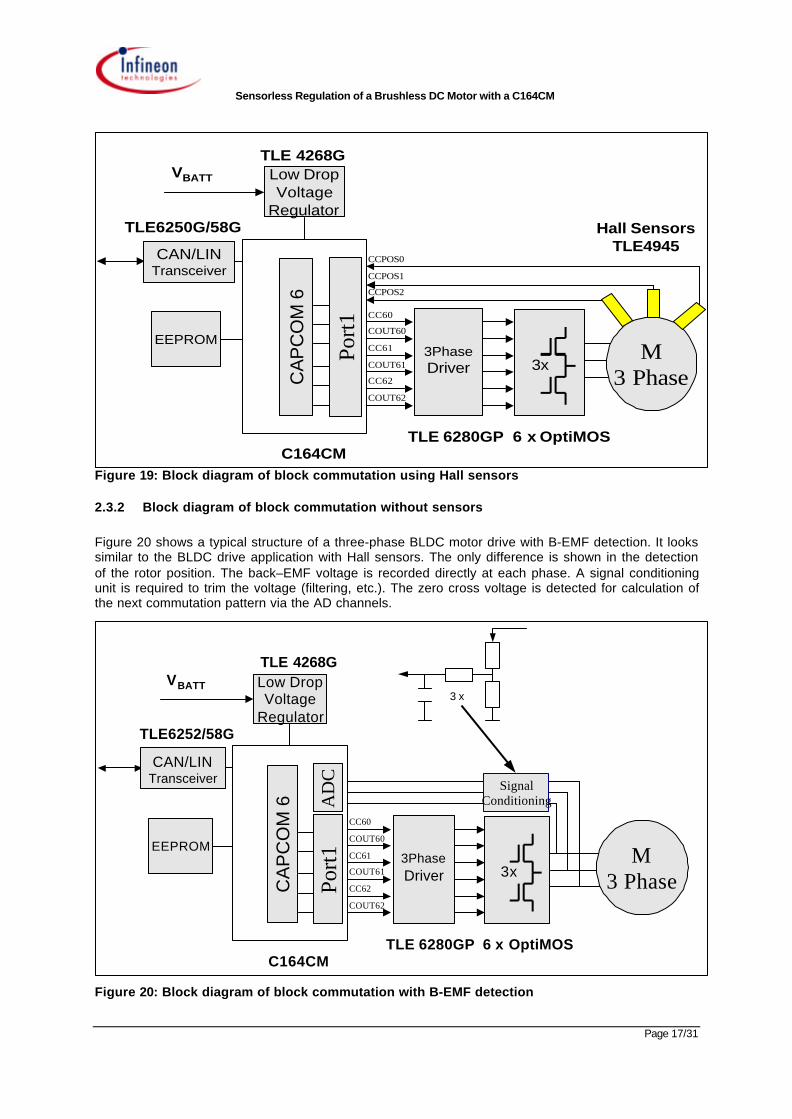
2.3.1 Block diagram of block commutation using Hall sensors
Figure 19 shows a typical structure of a three-phase BLDC motor drive suitable for use in automotiveapplications, e.g. fan cooling or water pump. The C164CM microcontroller generates the rotationpatterns for the stator field and can be used for speed or torque control. The TLE 6280 driver IC isused to provide the output signals for the 3-phase inverter and perform certain diagnostic functionssuch as short-circuit current protection, over-/undervoltage protection and overtemperature protection.OptiMOS devices arranged as three half-bridges switch the power to the corresponding phases of theBLDC motor.
Sensorless Regulation of a Brushless DC Motor with a C164CM
Page 17/31
C164CM
Port1
CCPOS2
CCPOS0
CCPOS1
COUT61
CC61
COUT60
CC60
CC62
COUT62
M3 Phase
TLE 6280GP 6 x OptiMOS
Low Drop VoltageRegulator
TLE 4268GVBATT
EEPROM
TLE6250G/58G Hall SensorsTLE4945CAN/LIN
Transceiver
CA
PC
OM
6
3PhaseDriver 3x
Figure 19: Block diagram of block commutation using Hall sensors
2.3.2 Block diagram of block commutation without sensors
Figure 20 shows a typical structure of a three-phase BLDC motor drive with B-EMF detection. It lookssimilar to the BLDC drive application with Hall sensors. The only difference is shown in the detectionof the rotor position. The back–EMF voltage is recorded directly at each phase. A signal conditioningunit is required to trim the voltage (filtering, etc.). The zero cross voltage is detected for calculation ofthe next commutation pattern via the AD channels.
C164CM
Port1 COUT61
CC61
COUT60
CC60
CC62
COUT62
M3 Phase
TLE 6280GP 6 x OptiMOS
Low Drop VoltageRegulator
TLE 4268GVBATT
EEPROM
TLE6252/58G
CAN/LINTransceiver
CA
PC
OM
6
3PhaseDriver 3x
SignalConditioningA
DC
3 x
Figure 20: Block diagram of block commutation with B-EMF detection
Sensorless Regulation of a Brushless DC Motor with a C164CM
Page 18/31
Figure 21 shows a brushless DC motor evaluation kit. It is subdivided into a microcontroller board anda power board. In conjunction with an application node and a PC-driven interface, customers may startimmediately with the evaluation of their own application.
Figure 21: BLDC motor drive evaluation boards
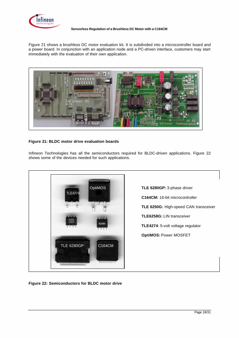
Infineon Technologies has all the semiconductors required for BLDC-driven applications. Figure 22shows some of the devices needed for such applications.
Figure 22: Semiconductors for BLDC motor drive
TLE 6280GP C164CM
TLE 6280GP: 3-phase driver
C164CM: 16-bit microcontroller
TLE 6250G: High-speed CAN transceiver
TLE6258G: LIN transceiver
TLE4274: 5-volt voltage regulator
OptiMOS: Power MOSFET
OptiMOSTLE4274
Sensorless Regulation of a Brushless DC Motor with a C164CM
Page 19/31
3 Block commutation mode with BACK-EMF detection
3.1 General
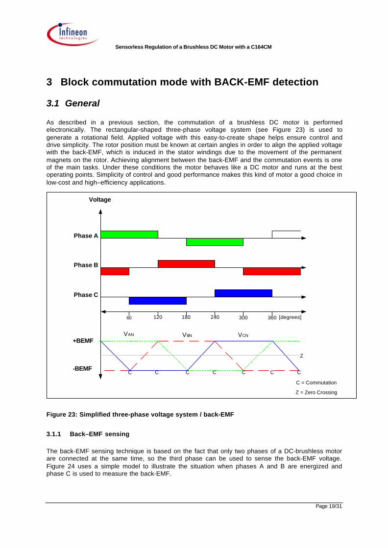
As described in a previous section, the commutation of a brushless DC motor is performedelectronically. The rectangular-shaped three-phase voltage system (see Figure 23) is used togenerate a rotational field. Applied voltage with this easy-to-create shape helps ensure control anddrive simplicity. The rotor position must be known at certain angles in order to align the applied voltagewith the back-EMF, which is induced in the stator windings due to the movement of the permanentmagnets on the rotor. Achieving alignment between the back-EMF and the commutation events is oneof the main tasks. Under these conditions the motor behaves like a DC motor and runs at the bestoperating points. Simplicity of control and good performance makes this kind of motor a good choice inlow-cost and high–efficiency applications.
Phase A
Phase B
Phase C
Voltage
60 120 180 240 300 360 [degrees]
VAN VBN VCN
C C C C C
Z
C
C = Commutation
Z = Zero Crossing
+BEMF
-BEMFC
Figure 23: Simplified three-phase voltage system / back-EMF
3.1.1 Back–EMF sensing
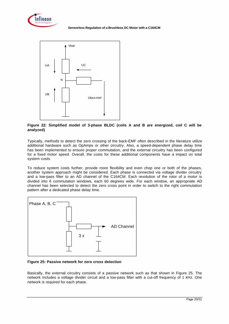
The back-EMF sensing technique is based on the fact that only two phases of a DC-brushless motorare connected at the same time, so the third phase can be used to sense the back-EMF voltage.Figure 24 uses a simple model to illustrate the situation when phases A and B are energized andphase C is used to measure the back-EMF.
Sensorless Regulation of a Brushless DC Motor with a C164CM
Page 20/31
UA
UB
N
UC
Vbat
UBack-EMF
Figure 22: Simplified model of 3-phase BLDC (coils A and B are energized, coil C will beanalyzed)
Typically, methods to detect the zero crossing of the back-EMF often described in the literature utilizeadditional hardware such as OpAmps or other circuitry. Also, a speed-dependent phase delay timehas been implemented to ensure proper commutation, and the external circuitry has been configuredfor a fixed motor speed. Overall, the costs for these additional components have a impact on totalsystem costs.
To reduce system costs further, provide more flexibility and even chop one or both of the phases,another system approach might be considered. Each phase is connected via voltage divider circuitryand a low-pass filter to an AD channel of the C164CM. Each revolution of the rotor of a motor isdivided into 6 commutation windows, each 60 degrees wide. For each window, an appropriate ADchannel has been selected to detect the zero cross point in order to switch to the right commutationpattern after a dedicated phase delay time.
AD Channel
3 x
Phase A, B, C
Figure 25: Passive network for zero cross detection
Basically, the external circuitry consists of a passive network such as that shown in Figure 25. Thenetwork includes a voltage divider circuit and a low-pass filter with a cut-off frequency of 1 kHz. Onenetwork is required for each phase.
Sensorless Regulation of a Brushless DC Motor with a C164CM
Page 21/31
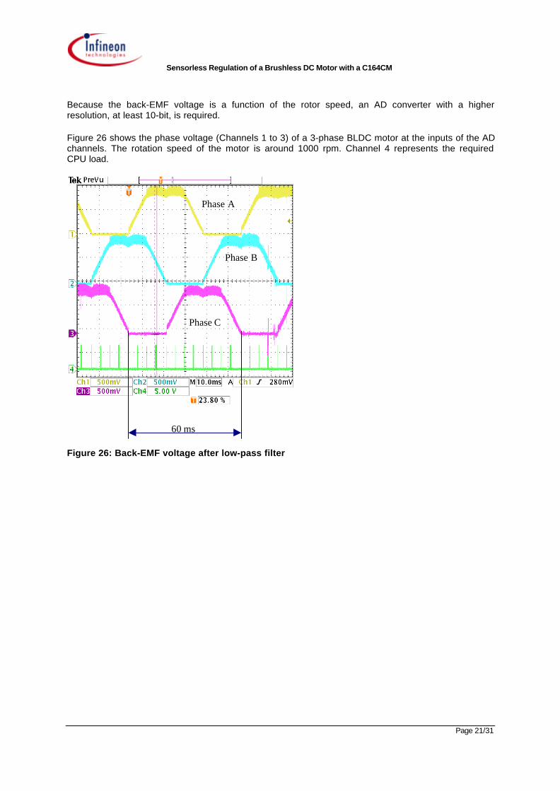
Because the back-EMF voltage is a function of the rotor speed, an AD converter with a higherresolution, at least 10-bit, is required.
Figure 26 shows the phase voltage (Channels 1 to 3) of a 3-phase BLDC motor at the inputs of the ADchannels. The rotation speed of the motor is around 1000 rpm. Channel 4 represents the requiredCPU load.
60 ms
Phase A
Phase B
Phase C
Figure 26: Back-EMF voltage after low-pass filter
Sensorless Regulation of a Brushless DC Motor with a C164CM
Page 22/31
3.2 Required peripherals
3.2.1 CAPCOM6
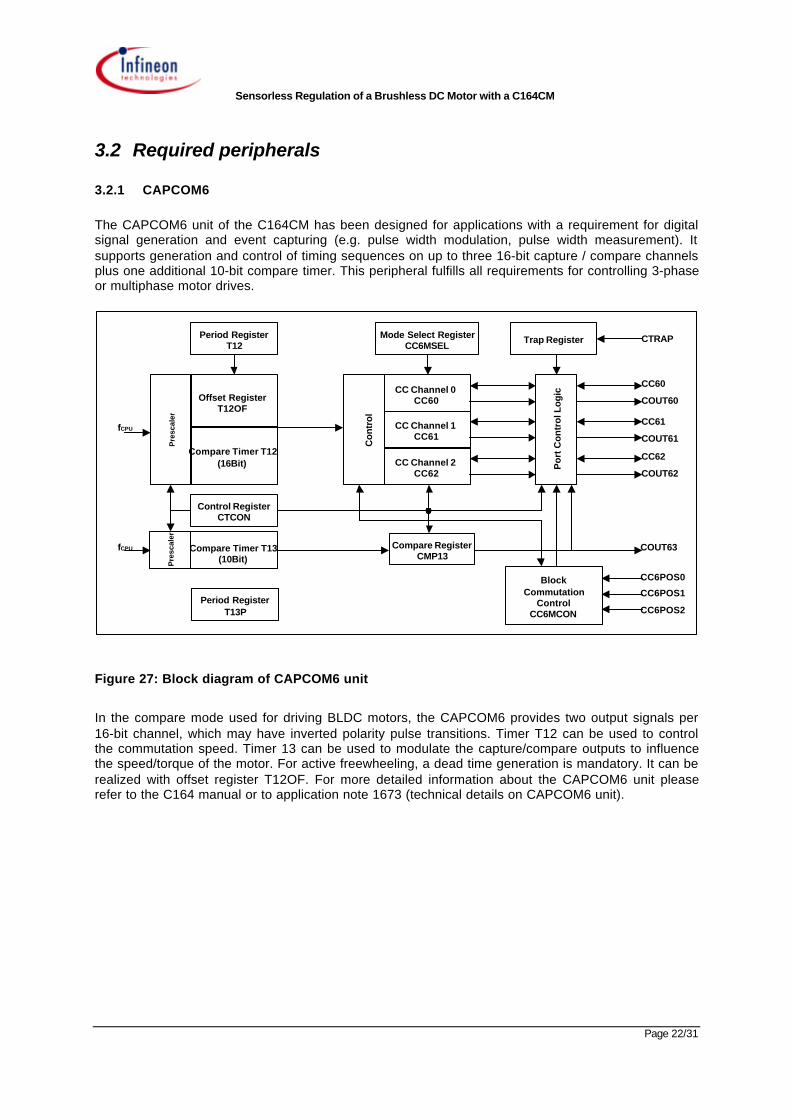
The CAPCOM6 unit of the C164CM has been designed for applications with a requirement for digitalsignal generation and event capturing (e.g. pulse width modulation, pulse width measurement). Itsupports generation and control of timing sequences on up to three 16-bit capture / compare channelsplus one additional 10-bit compare timer. This peripheral fulfills all requirements for controlling 3-phaseor multiphase motor drives.
CC Channel 0CC60
CC Channel 1CC61
CC Channel 2CC62
Con
trol
Mode Select RegisterCC6MSEL
Trap Register
Po
rt C
on
tro
l Lo
gic
Compare RegisterCMP13
Period RegisterT12
Pre
scal
er
Period RegisterT13P
Control RegisterCTCON
Offset RegisterT12OF
Compare Timer T12(16Bit)
BlockCommutation
ControlCC6MCON
Pre
scal
er
Compare Timer T13(10Bit)
CTRAP
CC60
COUT60
CC61
COUT61
CC62
COUT62
fCPU
fCPU COUT63
CC6POS0
CC6POS1
CC6POS2
Figure 27: Block diagram of CAPCOM6 unit
In the compare mode used for driving BLDC motors, the CAPCOM6 provides two output signals per16-bit channel, which may have inverted polarity pulse transitions. Timer T12 can be used to controlthe commutation speed. Timer 13 can be used to modulate the capture/compare outputs to influencethe speed/torque of the motor. For active freewheeling, a dead time generation is mandatory. It can berealized with offset register T12OF. For more detailed information about the CAPCOM6 unit pleaserefer to the C164 manual or to application note 1673 (technical details on CAPCOM6 unit).
Sensorless Regulation of a Brushless DC Motor with a C164CM
Page 23/31
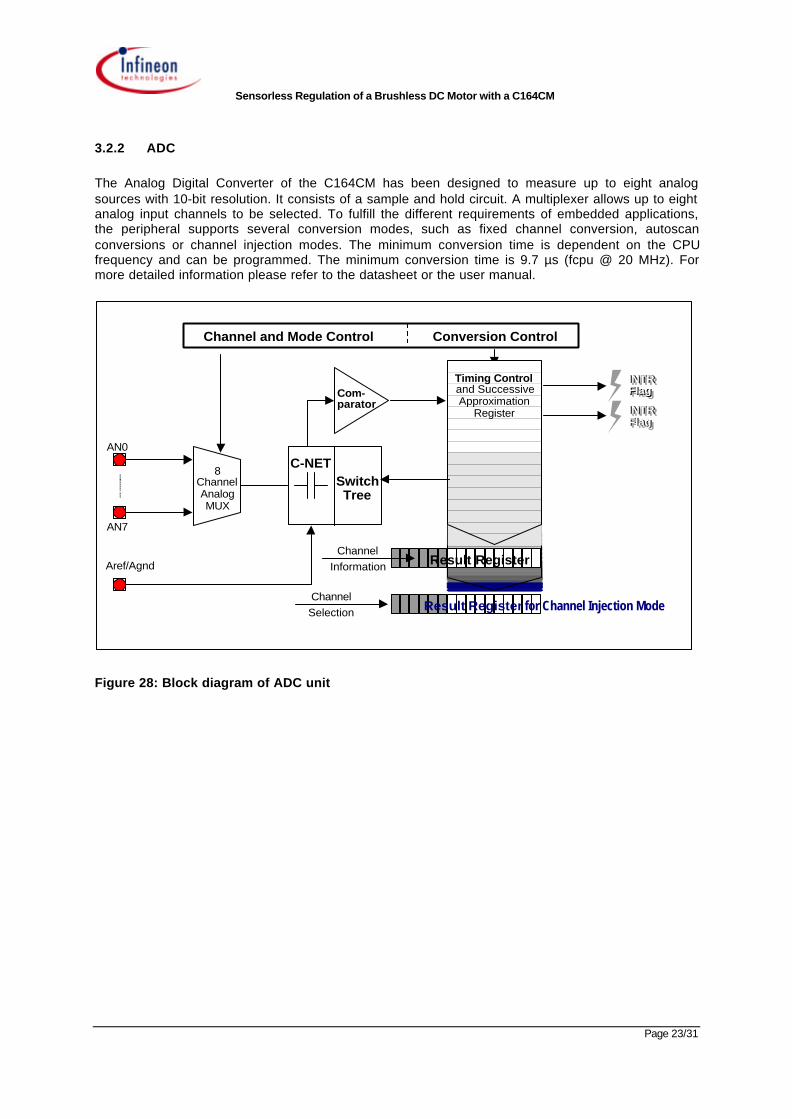
3.2.2 ADC
The Analog Digital Converter of the C164CM has been designed to measure up to eight analogsources with 10-bit resolution. It consists of a sample and hold circuit. A multiplexer allows up to eightanalog input channels to be selected. To fulfill the different requirements of embedded applications,the peripheral supports several conversion modes, such as fixed channel conversion, autoscanconversions or channel injection modes. The minimum conversion time is dependent on the CPUfrequency and can be programmed. The minimum conversion time is 9.7 µs (fcpu @ 20 MHz). Formore detailed information please refer to the datasheet or the user manual.
Channel and Mode Control Conversion ControlChannel and Mode Control Conversion Control
8ChannelAnalogMUX
C-NETSwitchTree
Com-parator
INTR FlagINTRINTR Flag Flag
INTR FlagINTRINTR Flag Flag
Timing Controland SuccessiveApproximation
Register
ChannelInformation Result Register
ChannelSelection Result Register for Channel Injection Mode
AN0
AN7
Aref/Agnd
Figure 28: Block diagram of ADC unit
Sensorless Regulation of a Brushless DC Motor with a C164CM
Page 24/31
4 Implementation
4.1 Functional description
4.1.1 General description
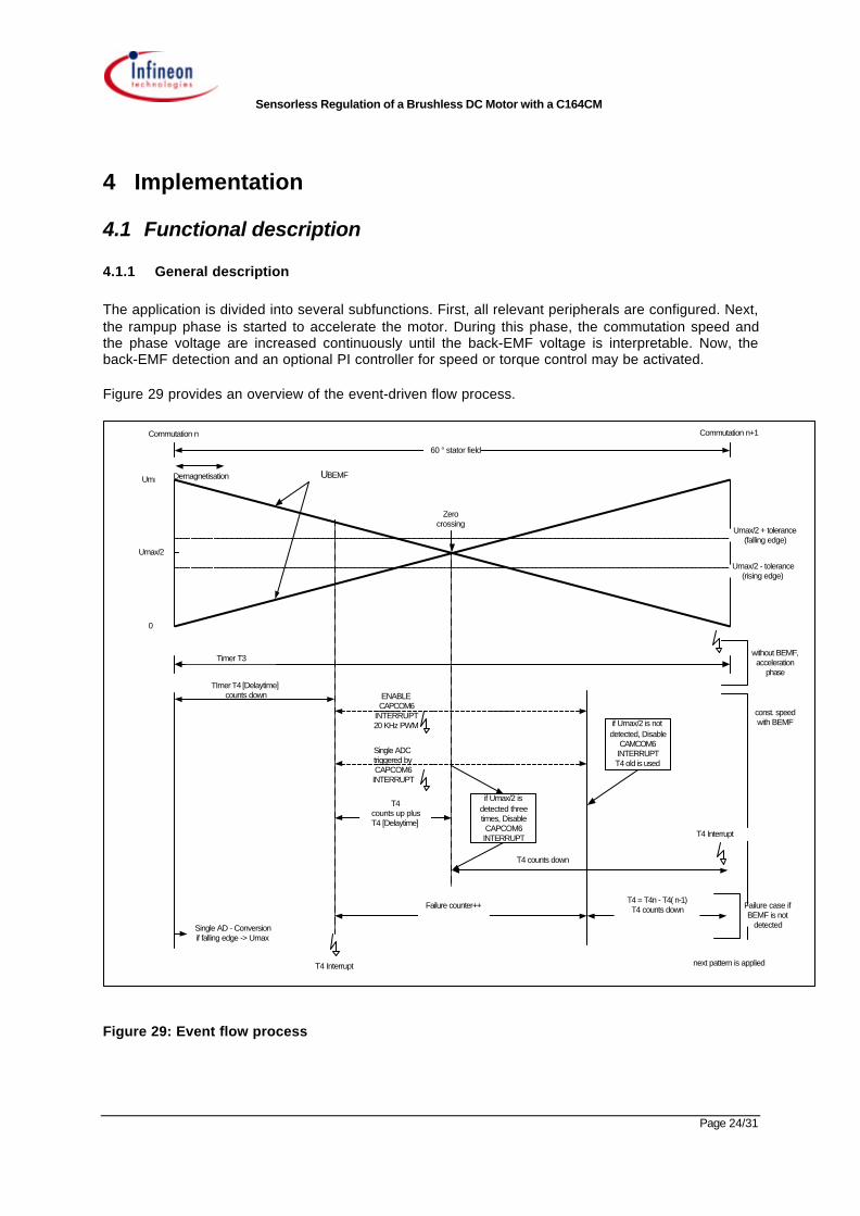
The application is divided into several subfunctions. First, all relevant peripherals are configured. Next,the rampup phase is started to accelerate the motor. During this phase, the commutation speed andthe phase voltage are increased continuously until the back-EMF voltage is interpretable. Now, theback-EMF detection and an optional PI controller for speed or torque control may be activated.
Figure 29 provides an overview of the event-driven flow process.
60 ° stator field
Umax/2
Umax
0
Umax/2 - tolerance(rising edge)
Umax/2 + tolerance(falling edge)
TImer T4 [Delaytime]counts down ENABLE
CAPCOM6INTERRUPT20 KHz PWM
Single ADCtriggered byCAPCOM6INTERRUPT
T4counts up plusT4 [Delaytime]
if Umax/2 isdetected threetimes, DisableCAPCOM6INTERRUPT
T4 counts down
without BEMF,acceleration
phase
const. speedwith BEMF
next pattern is applied
Single AD - Conversionif falling edge -> Umax
Failure counter++T4 = T4n - T4( n-1)T4 counts down Failure case if
BEMF is notdetected
Commutation n
Demagnetisation
Zerocrossing
Commutation n+1
Timer T3
T4 Interrupt
T4 Interrupt
if Umax/2 is notdetected, Disable
CAMCOM6INTERRUPTT4 old is used
Uphase(A,BC)UBEMF
Figure 29: Event flow process

Sensorless Regulation of a Brushless DC Motor with a C164CM
Page 25/31
4.1.2 Management of commutation, demagnetization and zero cross detection
The sensorless control process of the BLDC motor is based on the following events:
Commutation event (CAPCOM6 unit)
End of demagnetization (Timer T4)
Zero cross detection (ADC)
Each 60-degree window is initiated with a new commutation pattern. Timer T4 is utilized to generate adelay time between the start of the demagnetization impact and the point in time where the zero crossevent gets closer. This value of timer T4 is strongly dependent on the motor type and the requiredmotor speed. The timer T4 interrupt enables the CAPCOM6 interrupt. The CAPCOM6 interrupt forcesan AD conversion of the appropriate phase voltage every 50 µs (20 kHz PWM). If the convertedvoltage value is very close to the requested value three times, then a zero cross detection isrecognized. In the interim, timer T4 is used to monitor the elapsed time. Depending on motor type andspeed, the requested time is now calculated for the next commutation pattern. It is possible that thezero cross event is not recognized due to external noise. In this case a failure counter is incrementedand switches off the AD sampling of the phase voltage. The requested time for the next commutationpattern is calculated based on previous values. All tasks are interrupt-driven and consume littlemicrocontroller-related time.
4.2 Implementation of the software
The software is divided into several routines.
Initialization (ports, CAPCOM6, GPT1 (timer T3/T4))
State machine (6 commutation states)
PI controller for closed loop (optional)
Interrupt routines:
CAPCOM 6
Timer T4
Timer T3 (only used for the motor rampup time)
ADC
4.2.1 Initialization
A number of small routines perform all the necessary initializations before the motor is started:
Port initialization: P1L.0 – P1L5 (CCx,COUTx) output
Interrupt initialization: CAPCOM6 emergency (CC6EIC), CAPCOM6 (CC6CIC), ADCinterrupt (ADCIC), timer T3 (T3IC), timer T4 (T4IC).
CAPCOM6 initialization: Disable multichannel mode, passive output level is low, set timer T12(PWM 20 kHz), set compare register CCx to start value, center
Sensorless Regulation of a Brushless DC Motor with a C164CM
Page 26/31
aligned mode, active dead time generation, enable ext. trap functionfor emergency cases
ADC initialization: Select P5.3-P5.5 as AD channels, fixed-channel single conversion,sample time 1.6 µs, conversion time 9.7 µs
Timer initialization: Timer T3/T4 in timer mode, prescaler 16, external up/down controldisabled
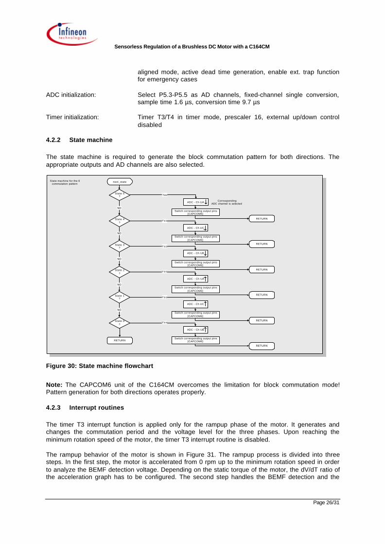
4.2.2 State machine
The state machine is required to generate the block commutation pattern for both directions. Theappropriate outputs and AD channels are also selected.
State 5?
NO
Yes
ADC - Ch UA
Switch corresponding output pins[CAPCOM6]
next_state
State 4?
NO
Y e s
ADC - Ch UC
Switch corresponding output pins[CAPCOM6]
State 3?
NO
Y e s
ADC - Ch UB
Switch corresponding output pins[CAPCOM6]
State 2?
NO
Y e s
ADC - Ch UA
Switch corresponding output pins[CAPCOM6]
State 1?
NO
Y e s
ADC - Ch UC
Switch corresponding output pins[CAPCOM6]
State 0?
Y e s
ADC - Ch UB
Switch corresponding output pins[CAPCOM6]
State machine for the 6commutation pattern
CorrespondingADC channel is selected
RETURN
RETURN
RETURN
RETURN
RETURN
RETURN
RETURN
Figure 30: State machine flowchart
Note: The CAPCOM6 unit of the C164CM overcomes the limitation for block commutation mode!Pattern generation for both directions operates properly.
4.2.3 Interrupt routines
The timer T3 interrupt function is applied only for the rampup phase of the motor. It generates andchanges the commutation period and the voltage level for the three phases. Upon reaching theminimum rotation speed of the motor, the timer T3 interrupt routine is disabled.
The rampup behavior of the motor is shown in Figure 31. The rampup process is divided into threesteps. In the first step, the motor is accelerated from 0 rpm up to the minimum rotation speed in orderto analyze the BEMF detection voltage. Depending on the static torque of the motor, the dV/dT ratio ofthe acceleration graph has to be configured. The second step handles the BEMF detection and the

Sensorless Regulation of a Brushless DC Motor with a C164CM
Page 27/31
synchronization to the appropriate commutation pattern. If the BEMF detection has been successful,then the motor speed can be accelerated up to the required value.
The timer T4 interrupt routine is enabled after back-EMF detection becomes active. It handles thewhole process of each 60-degree window (demagnetization, monitoring of the window length, point intime for commutation, etc.). ADC interrupt routines validate the current voltage level and take thedecision for zero cross detection. The CAPCOM6 interrupt routine forces an AD conversion every 50µs. It can be enabled by the timer T3 interrupt routine.
Mo
tor
Sp
eed
[rp
m]
Time [s]
BEMF active
dT
dV
less static torque
more static torque
Figure 31: Rampup behavior
ADC - INTERRUPT
Start BEMFmeasurement
YesNo
Get Umax
Iffalling edge
Rising edge
ADDAT <=Umax/2 + 5%
No
count ++
Yes
ADDAT >=Umax/2 - 5%
count ++
Yes
Yes
count >= 3 count >= 3
Yes
- Change Counting Direction- Disable CAPCOM6- Compare Rising- Edge INTERRUPT- Disable T3 INTERRUPT- Calculate rest time
Yes
No No
RETURN
ADC - INTERRUPT
fail_counter++
fail_counter >Max_v
RETURN
No No
No
Yes
Figure 32: Zero cross detection flowchart
Sensorless Regulation of a Brushless DC Motor with a C164CM
Page 28/31
4.3 Performance analysis
4.3.1 Hardware requirements
CPU:16xCPU (16-bit, 20 MHz)
ROM: 1KB – 2 KB depending on error detection requirements
RAM: 200 bytes plus system stack
Peripherals: CAPCOM6 unit: 16-bit timer, 50 ns resolution, three 16-bit capture/compare channels
ADC: 3-channel, 10-bit resolution, 9.7µs conversion time
Timer: 16 timer, 400ns resolution
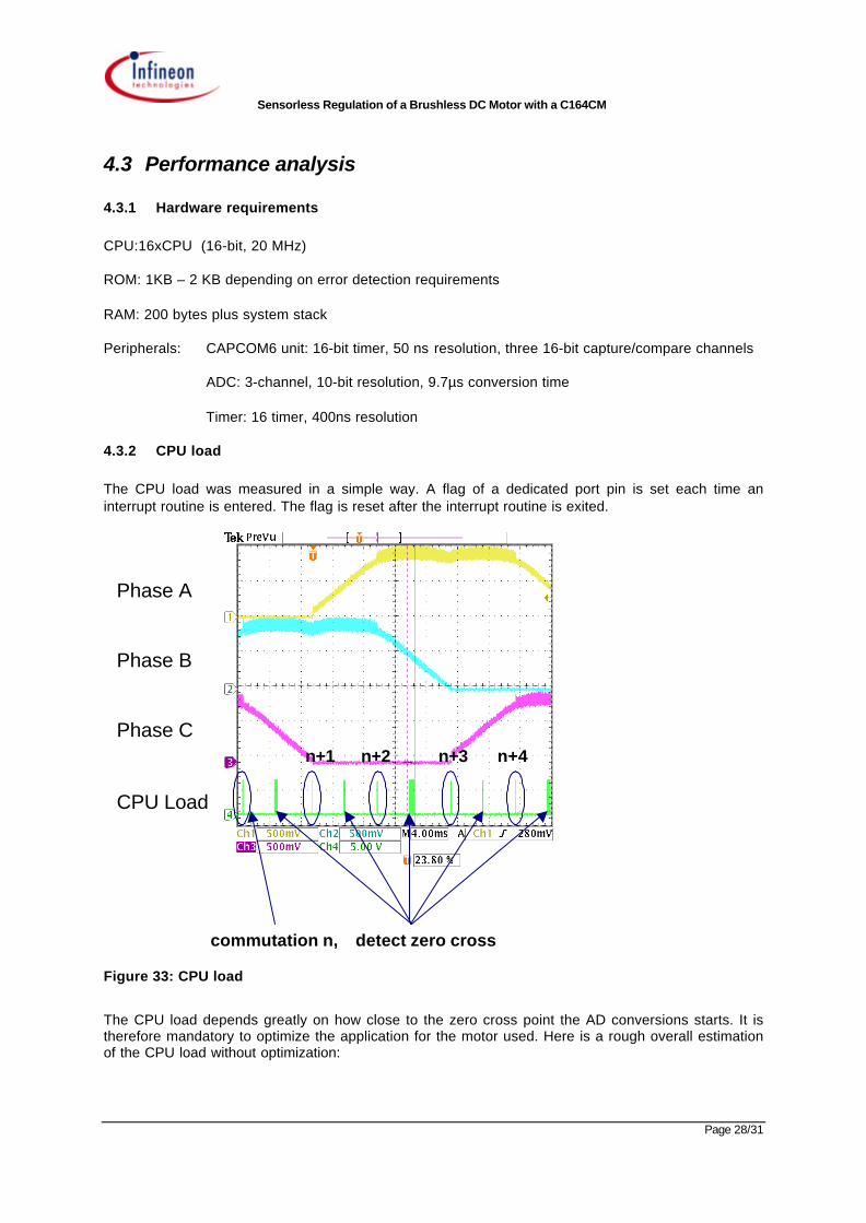
4.3.2 CPU load
The CPU load was measured in a simple way. A flag of a dedicated port pin is set each time aninterrupt routine is entered. The flag is reset after the interrupt routine is exited.
commutation n, detect zero cross
n+1 n+2 n+3 n+4
Phase A
Phase B
Phase C
CPU Load
Figure 33: CPU load
The CPU load depends greatly on how close to the zero cross point the AD conversions starts. It istherefore mandatory to optimize the application for the motor used. Here is a rough overall estimationof the CPU load without optimization:

Sensorless Regulation of a Brushless DC Motor with a C164CM
Page 29/31
CPU frequency: 20 MHz
Motor speed 1000 rpm, one pole pair
CPU load typically: 3 %
The CPU load depends greatly on how close to the zero cross point the AD conversion starts. TheCPU load may be decreased by using the DMA feature (PEC transfer) instead of continuousverification of the phase voltage.
Sensorless Regulation of a Brushless DC Motor with a C164CM
Page 30/31
5 Conclusion
There is an increasing demand in the automotive industry for applications using BLDC motors. In thepast, many applications were addressed with DC motors. Automotive suppliers would like to useBLDC motors in order to achieve greater robustness and efficiency. Currently, the only limitation is theprice gap between BLDC motors and DC motors. On the other hand, automotive suppliers areintensely price-driven and need smart solutions to meet the requirements of the market.
This application note aims to provide an understanding of the functionality of a BLDC motor, explainshow such a motor is driven, describes all the necessary components and the necessity of knowing thepositioning of a synchronous motor. Furthermore, the back-EMF technique is discussed and a methodto implement the back-EMF algorithm in the C164CM is presented. To achieve a goodprice/performance ratio, all the components used for back-EMF detection have been replaced bysoftware. Thanks to the high performance of the microcontroller and its powerful peripherals, thissoftware solution consumes only limited CPU resources.
The system approach discussed might be considered as a starting point for designing a completesystem-specific closed-loop BLDC application
Sensorless Regulation of a Brushless DC Motor with a C164CM
Page 31/31
6 Abbreviations
ADC: Analog Digital Converter
BACK-EMF : Back electromagnetic force
B6 : Bridge with 6 switches (e.g. MOSFET) for 3 phases
BLDC: Brushless DC
CAN: Controller Area Network
CAPCOM: Capture Compare Unit, peripheral that measure events or provide PWM signal
CPU: Central Processor Unit
EHPS: Electro Hydraulic Power Steering
LIN: Local Interconnect Network
PI: Proportional Integral
PWM: Pulse width modulation
ROM: Read only memory
RAM: Read Access Memory