Embed Size (px)
Citation preview

08-Oct-15
1
UNIT V
AUTOMOTIVE SENSORS AND ACTUATORS
• Introduction, basic sensor arrangement, Types
of sensors such as – oxygen sensors, Crank
angle position sensors -Fuel metering, vehicle
speed sensor and detonation sensor
• Altitude sensor, flow sensor. Throttle position
sensors,
• solenoids, stepper motors, relays.
SENSORS AND ACTUATORS
• In any control system, sensors provide measurements
of important plant variables in a format suitable for
the digital microcontroller.
• Similarly, actuators are electrically operated devices
that regulate inputs to the plant that directly control
its output.
• For example, as we shall see, fuel injectors are
electrically driven actuators that regulate the flow of
fuel into an engine for engine control applications.
08-Oct-15
2
BLOCK DIAGRAMS FOR VARIOUS
SYSTEM APPLICATIONS
TYPICAL ELECTRONIC ENGINE
CONTROL SYSTEM

08-Oct-15
3
VARIABLES TO BE MEASURED
• 1. Mass air flow (MAF) rate
• 2. Exhaust gas oxygen concentration (possibly heated)
• 3. Throttle plate angular position
• 4. Crankshaft angular position/RPM
• 5. Coolant temperature
• 6. Intake air temperature
• 7. Manifold absolute pressure (MAP)
• 8. Differential exhaust gas pressure
• 9. Vehicle speed
• 10. Transmission gear selector position
EXHAUST GAS OXYGEN SENSOR
• The amount of oxygen in the exhaust gas is used as an indirect
measurement of the air/fuel ratio.
• This sensor is often called a lambda sensor from the Greek letter
lambda (λ), which is commonly used to denote the equivalence
ratio:
• Whenever the air/fuel ratio is at stoichiometry the value for λ is 1.
• When the air–fuel mixture is too lean, the condition is represented
by lambda greater than one (denoted λ > 1).
• Conversely, when the air–fuel mixture is too rich, the condition is
represented by an equivalence ratio of lambda less than one (λ < 1).

08-Oct-15
4
EXHAUST GAS OXYGEN SENSOR
• The two types of EGO sensors that have been
used are based on the use of active oxides of
two types of materials.
• Zirconium dioxide (ZrO2) and
• Titanium dioxide (TiO2).
• The former is the most commonly used type
today.
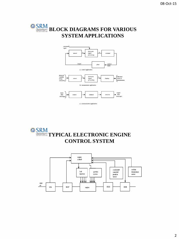
ZrO2 EGO SENSOR
• The EGO sensor consists of a thimble-shaped section of ZrO2
with thin platinum electrodes on the inside and outside of the
ZrO2.
• The inside electrode is exposed to air, and the outside
electrode is exposed to exhaust gas through a porous
protective overcoat
• EGO sensor operation is based on the distribution of oxygen
ions. An ion is an electrically charged atom.
• Oxygen ions have two excess electrons and each electron has a
negative charge; thus, oxygen ions are negatively charged.
• The ZrO2 has a tendency to attract the oxygen ions, which
accumulate on the ZrO2 surface just inside the platinum
electrodes.
08-Oct-15
5
ZrO2 EGO SENSOR
• The platinum plate on the air reference side of the ZrO2 is
exposed to a much higher concentration of oxygen ions than
the exhaust gas side.
• The air reference side becomes electrically more negative than
the exhaust gas side; therefore, an electric field exists across
the ZrO2 material and a voltage, Vo, results.
• The polarity of this voltage is positive on the exhaust gas side
and negative on the air reference side of the ZrO2.
• The magnitude of this voltage depends on the concentration of
oxygen in the exhaust gas and on the sensor temperature.

08-Oct-15
6
OPERATION MODE OF EGO
• Under certain conditions, the fuel control using an EGO sensor will
be operated in open-loop mode and for other conditions it will be
operated in closed-loop.
• The EGO sensor should not be used for control at temperatures
below about 300°C because the difference between rich and lean
voltages decreases rapidly with temperature in this region.
• This important property of the sensor is partly responsible for the
requirement to operate the fuel control system in the open-loop
mode at low exhaust temperature.
• Closed-loop operation with the EGO output voltage used as the error
input cannot begin until the EGO sensor temperature exceeds about
300°C.
HEATED EGO SENSORS
• The sensor is electrically heated from start-up until it yields an
output signal of sufficient magnitude to be useful in closed-
loop control.
• The HEGO sensor includes a section of resistance material.
Electrical power from the car battery is applied at start-up,
which quickly warms the sensor to usable temperatures.
• This heating potentially shortens the time interval until closed-
loop operation is possible, thereby minimizing the time during
warm-up that air/fuel ratio deviates from stoichiometry and
correspondingly reducing undesirable exhaust gas emissions.

08-Oct-15
7
DETONATION SENSOR
• Detonation sensor is employed in closed-loop
ignition timing to prevent undesirable knock.
• Knock can be described generally as a rapid rise in
cylinder pressure during combustion.
• It does not occur normally, but only under special
conditions.
• But occurs most commonly with high manifold
pressure and excessive spark advance.
• It is important to detect knock and avoid excessive
knock; otherwise, there may be damage to the engine

08-Oct-15
8
MAGNETOSTRICTION TYPE
• One way of controlling knocking is to sense when knocking begins
and then retard the ignition until the knocking stops. A key to the
control loop for this method is a knock sensor.
• Magnetostriction is a phenomenon whereby the magnetic properties
of a material depend on stress (due to an applied force).
• When sensing knock, the magnetostrictive rods, which are in a
magnetic field, change the flux field in the coil due to knock-
induced forces.
• This change in flux produces a voltage change in the coil. This
voltage is used to sense excessive knock
PIEZOELECTRIC TYPE
• This sensors use piezoelectric
crystals or the piezo-resistance of a
doped silicon semiconductor.
• This semiconductor senses the
knock and which produces the
voltage proportional to the amount
of knock produced in it
• Whichever type of sensor is used, it
forms a closed-loop system that
retards the ignition to reduce the
knock detected at the cylinders.
• The problem of detecting knock is
complicated by the presence of
other vibrations and noises in the
engine.
08-Oct-15
9
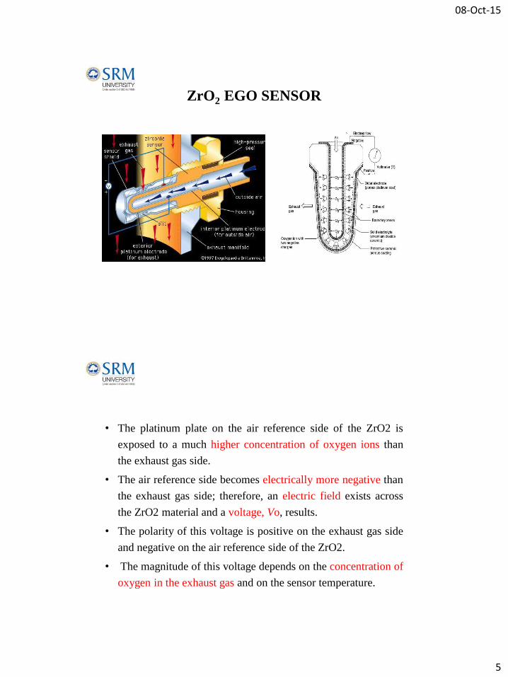
MASS AIRFLOW SENSOR
(Hot wire anemometer)
• The MAF sensor is a variation of a
classic air flow sensor that was
known as a hot wire anemometer
and was used.
• In the MAF, the hot-wire, or
sensing, element is replaced by a
hot-film structure mounted on a
substrate
• The film element is electrically
heated to a constant temperature
above that of the inlet air.
• The latter air temperature is sensed
using a solid-state temperature
sensor The hot-film element is
incorporated in a Wheatstone
bridge circuit . The power supply
for the bridge circuit comes from an
amplifier.
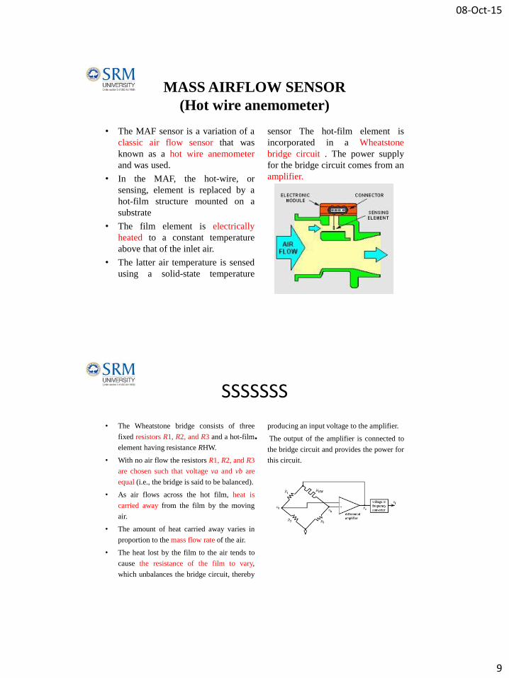
SSSSSSS
• The Wheatstone bridge consists of three
fixed resistors R1, R2, and R3 and a hot-film
element having resistance RHW.
• With no air flow the resistors R1, R2, and R3
are chosen such that voltage va and vb are
equal (i.e., the bridge is said to be balanced).
• As air flows across the hot film, heat is
carried away from the film by the moving
air.
• The amount of heat carried away varies in
proportion to the mass flow rate of the air.
• The heat lost by the film to the air tends to
cause the resistance of the film to vary,
which unbalances the bridge circuit, thereby
producing an input voltage to the amplifier.
• The output of the amplifier is connected to
the bridge circuit and provides the power for
this circuit.

08-Oct-15
10
MASS AIRFLOW SENSOR
(WEIGHTED FLAP TYPE)
CRANKSHAFT POSITION SENSOR
• This sensor consists of a permanent magnet with a coil of wire wound
around it. A steel disk that is mounted on the crankshaft (usually in front of
the engine) has tabs that pass between the pole pieces of this magnet.
• In Figure the steel disk has four protruding tabs, which is appropriate for an
8-cylinder engine.
• The passage of each tab can correspond to the TDC position of a cylinder
on its power stroke, although other reference positions are also possible.
• This sensor is of the magnetic reluctance type and is based on the concept
of a magnetic circuit. A magnetic circuit is a closed path through a
magnetic material.
• In the case of the sensor in Figure the magnetic circuit is the closed path
through the magnet material and across the gap between the pole pieces.

08-Oct-15
11
• when one of the tabs of the steel disk is located between the pole pieces of
the magnet, a large part of the gap between the pole pieces is filled by the
steel.
• Since the steel has a lower reluctance than air, the “flow” of magnetic flux
increases to a relatively large value.
• On the other hand, when a tab is not between the magnet pole pieces, the
gap is filled by air only. This creates a high-reluctance circuit for which the
magnetic flux is relatively small.
• The change in magnetic flux induces a voltage, Vo, in the sensing coil that
is proportional to the rate of change of the magnetic flux.
• It should be noted that if the disk is mounted on the crankshaft, then the
number of tabs for this crankshaft position sensor always will be half the
number of cylinders because it takes two crankshaft rotations for a
complete engine cycle.

08-Oct-15
12
CRANKSHAFT POSITION SENSOR
(Hall-effect Position Sensor)
• One of the main disadvantages of the magnetic
reluctance sensor is its lack of output when the engine
isn’t running.
• A crankshaft position sensor that avoids this problem
is the Hall-effect position sensor. This sensor can be
used to measure either camshaft position or
crankshaft position.
HALL EFFECT
• The Hall element is a small, thin,
flat slab of semiconductor material.
• When a current, I, is passed through
this slab by means of an external
circuit as shown in Figure 6.11a, a
voltage is developed across the slab
perpendicular to the direction of
current flow and perpendicular to
the direction of magnetic flux.
• This voltage is proportional to both
the current and magnetic flux
density that flows through the slab.
08-Oct-15
13
• It was shown in the discussion of the reluctance crankshaft position sensor that the
magnetic flux density for this configuration depends on the position of the tab.
• Recall that the magnetic flux is largest when one of the tabs is positioned
symmetrically between the magnet pole pieces and that this position normally
corresponds closely to TDC of one of the cylinders.
• The voltage waveform Vo that is produced by the Hall element in the position
sensor .Since Vo is proportional to the magnetic flux density, it reaches maximum
when any of the tabs is symmetrically located between the magnet pole pieces
(corresponding to TDC of a cylinder).
• If the disk is driven by the camshaft, then the disk must have as many tabs as the
engine has cylinders. Therefore, the disk shown would be for a 4-cylinder engine. It
is important to realize that voltage output versus crankshaft angle is independent of
engine speed.
• Thus, this sensor can be used for setting the engine timing when the engine is not
running
ENGINE SPEED SENSOR
• The position sensor discussed previously can be used to measure engine speed.
• The reluctance sensor is used in this case as an example; however, any of the other
position sensor techniques could be used as well. Refer to Figure and notice that the
four tabs will pass through the sensing coil once for each crankshaft revolution.
• Therefore, if we count the pulses of voltage from the sensing coil in one minute
and divide by four, we will know the engine speed in revolutions per minute
(RPM).
• This is easy to do with digital circuits. Precise timing circuits such as those used in
digital watches can start a counter circuit that will count pulses until the timing
circuit stops it.
• The counter can have the divide-by-four function included in it, or a separate
divider circuit may be used. In many cases, the actual RPM sensor disk is mounted
near the flywheel and has many more than four tabs; in such cases, the counter does
not actually count for a full minute before the speed is calculated, but the results are
the same.

08-Oct-15
14
THROTTLE ANGLE SENSOR
• The throttle plate is linked mechanically to the accelerator pedal.
• When the driver depresses the accelerator pedal, this linkage causes the
throttle plate angle to increase, allowing more air to enter the engine and
thereby increasing engine power
• Most throttle angle sensors are essentially potentiometers. A potentiometer
consists of a resistor with a movable contact
• A section of resistance material is placed in an arc around the pivot axis for
the movable contact. One end of the resistor is connected to ground, the
other to a fixed voltage V (e.g., 5 volts).
• The voltage at the contact point of the movable contact is proportional to
the angle (a) from the ground contact to the movable contact.
• Thus, v(a) = ka
• where v(a) is the voltage at the contact point, k is a constant, and a is the
angle of the contact point from the ground connection.
• This potentiometer can be
used to measure any angular
rotation. In particular, it is
well suited for measuring
throttle angle. The only
disadvantage to the
potentiometer for automotive
applications is its analog
output. For digital engine
control, the voltage v(a) must
be converted to digital format
using an analog-to-digital
converter.

08-Oct-15
15
FUEL METERING SENSOR
• In the fuel measuring system, two flow meters were used. The flow meter
used for measuring input fuel flow to the injector pump was a turbine type
and 6900 pulses were sent for each one liter of the fuel passing through the
meter.
• Besides, a sensor of the turbine type model was used to measure the fuel
returning from the injectors and the injector pump to the tank .
• So, in addition to the sensor installed where the fuel enters the injector
pump, another flow meter was located in the fuel line returning fuel to the
tank
• Total engine fuel consumption over a given distance of operation was
calculated as the difference between the readings of the two sensors, and
the result was saved in memory.
• Also, the amount of fuel consumed per second was measured by the
measurement system to obtain instantaneous consumption. The related data
were displayed by the monitoring unit and saved. Therefore, an electronic
board was used to receive and save the digital pulses sent by the flow meter
sensors.
ACTUATORS
08-Oct-15
16
SOLENOID VALVE
• A solenoid valve has two main parts: the solenoid and the valve.
• The solenoid converts electrical energy into mechanical energy which, in
turn, opens or closes the valve mechanically.
• A direct acting valve has only a small flow circuit, shown within section E
of this diagram (this section is mentioned below as a pilot valve).
• In this example, a diaphragm piloted valve multiplies this small pilot flow,
by using it to control the flow through a much larger orifice.
• Solenoid valves may use metal seals or rubber seals, and may also have
electrical interfaces to allow for easy control.
• A spring may be used to hold the valve opened (normally open) or closed
(normally closed) while the valve is not activated
• The water under pressure enters at A. B is an elastic diaphragm and above it is a
weak spring pushing it down. The diaphragm has a pinhole through its center which
allows a very small amount of water to flow through it.
• This water fills the cavity C on the other side of the diaphragm so that pressure is
equal on both sides of the diaphragm, however the compressed spring supplies a net
downward force
• Once the diaphragm closes the valve, the pressure on the outlet side of its bottom is
reduced, and the greater pressure above holds it even more firmly closed.
• Thus, the spring is irrelevant to holding the valve closed.
• The above all works because the small drain passage D was blocked by a pin which
is the armature of the solenoid E and which is pushed down by a spring. If current
is passed through the solenoid, the pin is withdrawn via magnetic force, and the
water in chamber C drains out the passage D faster than the pinhole can refill it.

08-Oct-15
17
• The pressure in chamber C drops and
the incoming pressure lifts the
diaphragm, thus opening the main
valve. Water now flows directly
from A to F.
• When the solenoid is again deactivated
and the passage D is closed again, the
spring needs very little force to push the
diaphragm down again and the main
valve closes.
• In practice there is often no separate
spring; the elastomer diaphragm is
molded so that it functions as its own
spring, preferring to be in the closed
shape
STEPPER MOTOR
• A stepper motor or step motor or stepping motor is a
brushless DC electric motor that divides a full
rotation into a number of equal steps.
08-Oct-15
18
FUNDAMENTALS OF OPERATION
• The stepper motor is known by its property to convert a train of input pulses (typically square
wave pulses) into a precisely defined increment in the shaft position.
• Each pulse moves the shaft through a fixed angle.
• Stepper motors effectively have multiple "toothed" electromagnets arranged around a central
gear-shaped piece of iron.
• The electromagnets are energized by an external driver circuit or a microcontroller.
• To make the motor shaft turn, first, one electromagnet is given power, which magnetically
attracts the gear's teeth.
• When the gear's teeth are aligned to the first electromagnet, they are slightly offset from the
next electromagnet.
• This means that when the next electromagnet is turned on and the first is turned off, the gear
rotates slightly to align with the next one
• . From there the process is repeated. Each of those rotations is called a "step", with an integer
number of steps making a full rotation. In that way, the motor can be turned by a precise angle
RELAYS
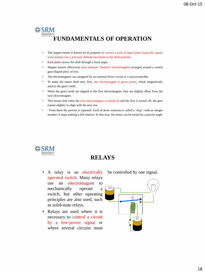
• A relay is an electrically
operated switch. Many relays
use an electromagnet to
mechanically operate a
switch, but other operating
principles are also used, such
as solid-state relays.
• Relays are used where it is
necessary to control a circuit
by a low-power signal or
where several circuits must
be controlled by one signal.

08-Oct-15
19
WORKING
• When an electric current is passed through the coil it generates
a magnetic field that activates the armature, and the
consequent movement of the movable contact(s) either makes
or breaks (depending upon construction) a connection with a
fixed contact.
• If the set of contacts was closed when the relay was de-
energized, then the movement opens the contacts and breaks
the connection, and vice versa if the contacts were open.
• When the current to the coil is switched off, the armature is
returned by a force, approximately half as strong as the
magnetic force, to its relaxed position.

![Sensors and Actuators B: Chemicalfaculty.iitmandi.ac.in/~satinder/files/Journals/45.pdf · sensors, micro-interdigitated electrodes ( -IDEs) are employed extensively [13]. The output](https://img.pdfslide.net/doc/110x75/5f5dda269910e76c92579ae2/sensors-and-actuators-b-satinderfilesjournals45pdf-sensors-micro-interdigitated.jpg)

![Sensors and Actuators A: Physical · Fayyaz Shahandashti et al. / Sensors and Actuators A 295 (2019) 678–686 679 tems [9,10]. Reusable, flexible, and preferably washable electrodes](https://img.pdfslide.net/doc/110x75/60276ef97d67270261037d06/sensors-and-actuators-a-physical-fayyaz-shahandashti-et-al-sensors-and-actuators.jpg)