Embed Size (px)
Citation preview

GEMeasurement & Control Flow
Sentinel™ LCT4User’s Manual
910-297 Rev. AFebruary 2014


Sentinel™ LCT4Ultrasonic Flowmeter for Liquid Custody Transfer Measurement
User’s Manual
910-297 Rev. AFebruary 2014
www.ge-mcs.com
©2014 General Electric Company. All rights reserved.Technical content subject to change without notice.

[no content intended for this page]

Preface
Information Paragraphs
• Note paragraphs provide information that provides a deeper understanding of the situation, but is not essential to the proper completion of the instructions.
• Important paragraphs provide information that emphasizes instructions that are essential to proper setup of the equipment. Failure to follow these instructions carefully may cause unreliable performance.
• Caution! paragraphs provide information that alerts the operator to a hazardous situation that can cause damage to property or equipment.
• Warning! paragraphs provide information that alerts the operator to a hazardous situation that can cause injury to personnel. Cautionary information is also included, when applicable.
Safety Issues
WARNING! It is the responsibility of the user to make sure all local, county, state and national codes, regulations, rules and laws related to safety and safe operating conditions are met for each installation.
Description of Symbols
Pay special attention to this section!
No smoking!
Warning — danger area!
Highly inflammable!
Sentinel™ LCT4 User’s Manual iii

Preface
Auxiliary Equipment
Local Safety Standards
The user must make sure that he operates all auxiliary equipment in accordance with local codes, standards, regulations, or laws applicable to safety.
Working Area
WARNING! Auxiliary equipment may have both manual and automatic modes of operation. As equipment can move suddenly and without warning, do not enter the work cell of this equipment during automatic operation, and do not enter the work envelope of this equipment during manual operation. If you do, serious injury can result.
WARNING! Make sure that power to the auxiliary equipment is turned OFF and locked out before you perform maintenance procedures on the equipment.
Qualification of Personnel
Make sure that all personnel have manufacturer-approved training applicable to the auxiliary equipment.
Personal Safety Equipment
Make sure that operators and maintenance personnel have all safety equipment applicable to the auxiliary equipment. Examples include safety glasses, protective headgear, safety shoes, etc.
Unauthorized Operation
Make sure that unauthorized personnel cannot gain access to the operation of the equipment.
iv Sentinel™ LCT4 User’s Manual

Preface
Environmental Compliance
Waste Electrical and Electronic Equipment (WEEE) Directive
GE Measurement & Control is an active participant in Europe’s Waste Electrical and Electronic Equipment (WEEE) take-back initiative, directive 2002/96/EC.
The equipment that you bought has required the extraction and use of natural resources for its production. It may contain hazardous substances that could impact health and the environment.
In order to avoid the dissemination of those substances in our environment and to diminish the pressure on the natural resources, we encourage you to use the appropriate take-back systems. Those systems will reuse or recycle most of the materials of your end life equipment in a sound way.
The crossed-out wheeled bin symbol invites you to use those systems.
If you need more information on the collection, reuse and recycling systems, please contact your local or regional waste administration.
Visit http://www.ge-mcs.com/en/about-us/environmental-health-and-safety/1741-weee-req.html for take-back instructions and more information about this initiative.
Sentinel™ LCT4 User’s Manual v

Preface
vi Sentinel™ LCT4 User’s Manual

Contents
Chapter 1. Features and Capabilities
1.1 Overview. . . . . . . . . . . . . . . . . . . . . . . . . . . . . . . . . . . . . . . . . . . . . . . . . . . . . . . . . . . . . . . . . . . . . . . . . . . . . . . . . . . . . . . . . . . . . . .1
1.1.1 Applications . . . . . . . . . . . . . . . . . . . . . . . . . . . . . . . . . . . . . . . . . . . . . . . . . . . . . . . . . . . . . . . . . . . . . . . . . . . . . . . . . . . .11.1.2 Advantages . . . . . . . . . . . . . . . . . . . . . . . . . . . . . . . . . . . . . . . . . . . . . . . . . . . . . . . . . . . . . . . . . . . . . . . . . . . . . . . . . . . .11.1.3 Meter Components . . . . . . . . . . . . . . . . . . . . . . . . . . . . . . . . . . . . . . . . . . . . . . . . . . . . . . . . . . . . . . . . . . . . . . . . . . . . .21.1.4 Marking and Labeling . . . . . . . . . . . . . . . . . . . . . . . . . . . . . . . . . . . . . . . . . . . . . . . . . . . . . . . . . . . . . . . . . . . . . . . . . . .4
1.2 Theory of Operation . . . . . . . . . . . . . . . . . . . . . . . . . . . . . . . . . . . . . . . . . . . . . . . . . . . . . . . . . . . . . . . . . . . . . . . . . . . . . . . . . . . .7
1.2.1 Transit-Time Method. . . . . . . . . . . . . . . . . . . . . . . . . . . . . . . . . . . . . . . . . . . . . . . . . . . . . . . . . . . . . . . . . . . . . . . . . . . .81.2.2 Transducers . . . . . . . . . . . . . . . . . . . . . . . . . . . . . . . . . . . . . . . . . . . . . . . . . . . . . . . . . . . . . . . . . . . . . . . . . . . . . . . . . . . .81.2.3 Multipath Design. . . . . . . . . . . . . . . . . . . . . . . . . . . . . . . . . . . . . . . . . . . . . . . . . . . . . . . . . . . . . . . . . . . . . . . . . . . . . . . .91.2.4 Flow Profile . . . . . . . . . . . . . . . . . . . . . . . . . . . . . . . . . . . . . . . . . . . . . . . . . . . . . . . . . . . . . . . . . . . . . . . . . . . . . . . . . . . . .91.2.5 Maximum and Minimum Flow . . . . . . . . . . . . . . . . . . . . . . . . . . . . . . . . . . . . . . . . . . . . . . . . . . . . . . . . . . . . . . . . . .10
1.3 Specifications . . . . . . . . . . . . . . . . . . . . . . . . . . . . . . . . . . . . . . . . . . . . . . . . . . . . . . . . . . . . . . . . . . . . . . . . . . . . . . . . . . . . . . . . .11
1.3.1 Operation and Performance. . . . . . . . . . . . . . . . . . . . . . . . . . . . . . . . . . . . . . . . . . . . . . . . . . . . . . . . . . . . . . . . . . . .111.3.2 Meter Body . . . . . . . . . . . . . . . . . . . . . . . . . . . . . . . . . . . . . . . . . . . . . . . . . . . . . . . . . . . . . . . . . . . . . . . . . . . . . . . . . . . .121.3.3 Electronics. . . . . . . . . . . . . . . . . . . . . . . . . . . . . . . . . . . . . . . . . . . . . . . . . . . . . . . . . . . . . . . . . . . . . . . . . . . . . . . . . . . . .171.3.4 Custody Transfer Approvals . . . . . . . . . . . . . . . . . . . . . . . . . . . . . . . . . . . . . . . . . . . . . . . . . . . . . . . . . . . . . . . . . . . .181.3.5 Standards . . . . . . . . . . . . . . . . . . . . . . . . . . . . . . . . . . . . . . . . . . . . . . . . . . . . . . . . . . . . . . . . . . . . . . . . . . . . . . . . . . . . .19
1.4 Maximum Allowable Operating Data . . . . . . . . . . . . . . . . . . . . . . . . . . . . . . . . . . . . . . . . . . . . . . . . . . . . . . . . . . . . . . . . . . .19
1.4.1 Operating and Storage Temperatures. . . . . . . . . . . . . . . . . . . . . . . . . . . . . . . . . . . . . . . . . . . . . . . . . . . . . . . . . . .191.4.2 Operating Pressures . . . . . . . . . . . . . . . . . . . . . . . . . . . . . . . . . . . . . . . . . . . . . . . . . . . . . . . . . . . . . . . . . . . . . . . . . . .191.4.3 Weight . . . . . . . . . . . . . . . . . . . . . . . . . . . . . . . . . . . . . . . . . . . . . . . . . . . . . . . . . . . . . . . . . . . . . . . . . . . . . . . . . . . . . . . .201.4.4 Flowrates . . . . . . . . . . . . . . . . . . . . . . . . . . . . . . . . . . . . . . . . . . . . . . . . . . . . . . . . . . . . . . . . . . . . . . . . . . . . . . . . . . . . .211.4.5 Allowable Fluids . . . . . . . . . . . . . . . . . . . . . . . . . . . . . . . . . . . . . . . . . . . . . . . . . . . . . . . . . . . . . . . . . . . . . . . . . . . . . . .211.4.6 Loads and Forces . . . . . . . . . . . . . . . . . . . . . . . . . . . . . . . . . . . . . . . . . . . . . . . . . . . . . . . . . . . . . . . . . . . . . . . . . . . . . .221.4.7 Description of Different Operating Conditions . . . . . . . . . . . . . . . . . . . . . . . . . . . . . . . . . . . . . . . . . . . . . . . . . . .22
1.5 Certification. . . . . . . . . . . . . . . . . . . . . . . . . . . . . . . . . . . . . . . . . . . . . . . . . . . . . . . . . . . . . . . . . . . . . . . . . . . . . . . . . . . . . . . . . . .23
1.5.1 Pressure Equipment Directive (PED) . . . . . . . . . . . . . . . . . . . . . . . . . . . . . . . . . . . . . . . . . . . . . . . . . . . . . . . . . . . . .231.5.2 Canadian Registration Number (CRN) . . . . . . . . . . . . . . . . . . . . . . . . . . . . . . . . . . . . . . . . . . . . . . . . . . . . . . . . . . .231.5.3 Custody Transfer Performance Approvals . . . . . . . . . . . . . . . . . . . . . . . . . . . . . . . . . . . . . . . . . . . . . . . . . . . . . . .23
1.6 List of Reference Drawings and Documentation. . . . . . . . . . . . . . . . . . . . . . . . . . . . . . . . . . . . . . . . . . . . . . . . . . . . . . . . .24
1.6.1 Wiring Diagrams. . . . . . . . . . . . . . . . . . . . . . . . . . . . . . . . . . . . . . . . . . . . . . . . . . . . . . . . . . . . . . . . . . . . . . . . . . . . . . .241.6.2 Outline and Installation Diagrams . . . . . . . . . . . . . . . . . . . . . . . . . . . . . . . . . . . . . . . . . . . . . . . . . . . . . . . . . . . . . .241.6.3 Manuals . . . . . . . . . . . . . . . . . . . . . . . . . . . . . . . . . . . . . . . . . . . . . . . . . . . . . . . . . . . . . . . . . . . . . . . . . . . . . . . . . . . . . . .24
1.7 Disclaimer . . . . . . . . . . . . . . . . . . . . . . . . . . . . . . . . . . . . . . . . . . . . . . . . . . . . . . . . . . . . . . . . . . . . . . . . . . . . . . . . . . . . . . . . . . . .25
1.8 Warnings and Cautions . . . . . . . . . . . . . . . . . . . . . . . . . . . . . . . . . . . . . . . . . . . . . . . . . . . . . . . . . . . . . . . . . . . . . . . . . . . . . . . .25
Sentinel™ LCT4 User’s Manual vii
Contents
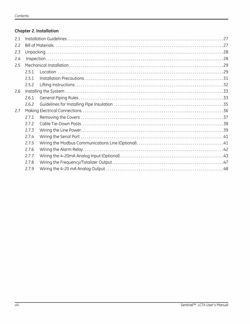
Chapter 2. Installation
2.1 Installation Guidelines . . . . . . . . . . . . . . . . . . . . . . . . . . . . . . . . . . . . . . . . . . . . . . . . . . . . . . . . . . . . . . . . . . . . . . . . . . . . . . . . .27
2.2 Bill of Materials. . . . . . . . . . . . . . . . . . . . . . . . . . . . . . . . . . . . . . . . . . . . . . . . . . . . . . . . . . . . . . . . . . . . . . . . . . . . . . . . . . . . . . . .27
2.3 Unpacking . . . . . . . . . . . . . . . . . . . . . . . . . . . . . . . . . . . . . . . . . . . . . . . . . . . . . . . . . . . . . . . . . . . . . . . . . . . . . . . . . . . . . . . . . . . .28
2.4 Inspection . . . . . . . . . . . . . . . . . . . . . . . . . . . . . . . . . . . . . . . . . . . . . . . . . . . . . . . . . . . . . . . . . . . . . . . . . . . . . . . . . . . . . . . . . . . .28
2.5 Mechanical Installation . . . . . . . . . . . . . . . . . . . . . . . . . . . . . . . . . . . . . . . . . . . . . . . . . . . . . . . . . . . . . . . . . . . . . . . . . . . . . . . .29
2.5.1 Location . . . . . . . . . . . . . . . . . . . . . . . . . . . . . . . . . . . . . . . . . . . . . . . . . . . . . . . . . . . . . . . . . . . . . . . . . . . . . . . . . . . . . .292.5.1 Installation Precautions . . . . . . . . . . . . . . . . . . . . . . . . . . . . . . . . . . . . . . . . . . . . . . . . . . . . . . . . . . . . . . . . . . . . . . . .312.5.2 Lifting Instructions . . . . . . . . . . . . . . . . . . . . . . . . . . . . . . . . . . . . . . . . . . . . . . . . . . . . . . . . . . . . . . . . . . . . . . . . . . . . .32
2.6 Installing the System . . . . . . . . . . . . . . . . . . . . . . . . . . . . . . . . . . . . . . . . . . . . . . . . . . . . . . . . . . . . . . . . . . . . . . . . . . . . . . . . . .33
2.6.1 General Piping Rules . . . . . . . . . . . . . . . . . . . . . . . . . . . . . . . . . . . . . . . . . . . . . . . . . . . . . . . . . . . . . . . . . . . . . . . . . . .332.6.2 Guidelines for Installing Pipe Insulation . . . . . . . . . . . . . . . . . . . . . . . . . . . . . . . . . . . . . . . . . . . . . . . . . . . . . . . . .35
2.7 Making Electrical Connections . . . . . . . . . . . . . . . . . . . . . . . . . . . . . . . . . . . . . . . . . . . . . . . . . . . . . . . . . . . . . . . . . . . . . . . . .36
2.7.1 Removing the Covers . . . . . . . . . . . . . . . . . . . . . . . . . . . . . . . . . . . . . . . . . . . . . . . . . . . . . . . . . . . . . . . . . . . . . . . . . .372.7.2 Cable Tie-Down Posts. . . . . . . . . . . . . . . . . . . . . . . . . . . . . . . . . . . . . . . . . . . . . . . . . . . . . . . . . . . . . . . . . . . . . . . . . .382.7.3 Wiring the Line Power. . . . . . . . . . . . . . . . . . . . . . . . . . . . . . . . . . . . . . . . . . . . . . . . . . . . . . . . . . . . . . . . . . . . . . . . . .392.7.4 Wiring the Serial Port . . . . . . . . . . . . . . . . . . . . . . . . . . . . . . . . . . . . . . . . . . . . . . . . . . . . . . . . . . . . . . . . . . . . . . . . . .412.7.5 Wiring the Modbus Communications Line (Optional) . . . . . . . . . . . . . . . . . . . . . . . . . . . . . . . . . . . . . . . . . . . . .412.7.6 Wiring the Alarm Relay. . . . . . . . . . . . . . . . . . . . . . . . . . . . . . . . . . . . . . . . . . . . . . . . . . . . . . . . . . . . . . . . . . . . . . . . .422.7.7 Wiring the 4-20mA Analog Input (Optional). . . . . . . . . . . . . . . . . . . . . . . . . . . . . . . . . . . . . . . . . . . . . . . . . . . . . .432.7.8 Wiring the Frequency/Totalizer Output. . . . . . . . . . . . . . . . . . . . . . . . . . . . . . . . . . . . . . . . . . . . . . . . . . . . . . . . . .472.7.9 Wiring the 4-20 mA Analog Output . . . . . . . . . . . . . . . . . . . . . . . . . . . . . . . . . . . . . . . . . . . . . . . . . . . . . . . . . . . . .48
viii Sentinel™ LCT4 User’s Manual
Contents
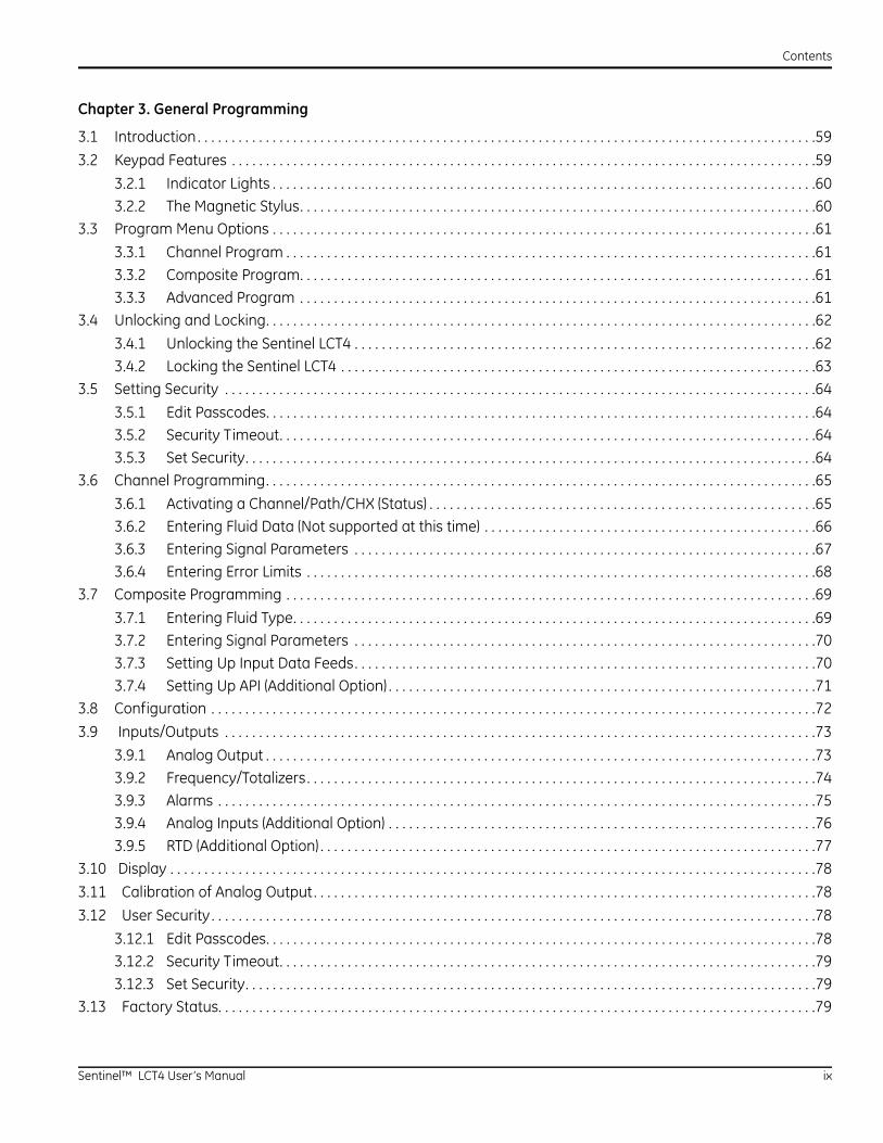
Chapter 3. General Programming
3.1 Introduction . . . . . . . . . . . . . . . . . . . . . . . . . . . . . . . . . . . . . . . . . . . . . . . . . . . . . . . . . . . . . . . . . . . . . . . . . . . . . . . . . . . . . . . . . . .59
3.2 Keypad Features . . . . . . . . . . . . . . . . . . . . . . . . . . . . . . . . . . . . . . . . . . . . . . . . . . . . . . . . . . . . . . . . . . . . . . . . . . . . . . . . . . . . . .59
3.2.1 Indicator Lights . . . . . . . . . . . . . . . . . . . . . . . . . . . . . . . . . . . . . . . . . . . . . . . . . . . . . . . . . . . . . . . . . . . . . . . . . . . . . . . .603.2.2 The Magnetic Stylus. . . . . . . . . . . . . . . . . . . . . . . . . . . . . . . . . . . . . . . . . . . . . . . . . . . . . . . . . . . . . . . . . . . . . . . . . . . .60
3.3 Program Menu Options . . . . . . . . . . . . . . . . . . . . . . . . . . . . . . . . . . . . . . . . . . . . . . . . . . . . . . . . . . . . . . . . . . . . . . . . . . . . . . . .61
3.3.1 Channel Program . . . . . . . . . . . . . . . . . . . . . . . . . . . . . . . . . . . . . . . . . . . . . . . . . . . . . . . . . . . . . . . . . . . . . . . . . . . . . .613.3.2 Composite Program. . . . . . . . . . . . . . . . . . . . . . . . . . . . . . . . . . . . . . . . . . . . . . . . . . . . . . . . . . . . . . . . . . . . . . . . . . . .613.3.3 Advanced Program . . . . . . . . . . . . . . . . . . . . . . . . . . . . . . . . . . . . . . . . . . . . . . . . . . . . . . . . . . . . . . . . . . . . . . . . . . . .61
3.4 Unlocking and Locking. . . . . . . . . . . . . . . . . . . . . . . . . . . . . . . . . . . . . . . . . . . . . . . . . . . . . . . . . . . . . . . . . . . . . . . . . . . . . . . . .62
3.4.1 Unlocking the Sentinel LCT4 . . . . . . . . . . . . . . . . . . . . . . . . . . . . . . . . . . . . . . . . . . . . . . . . . . . . . . . . . . . . . . . . . . . .623.4.2 Locking the Sentinel LCT4 . . . . . . . . . . . . . . . . . . . . . . . . . . . . . . . . . . . . . . . . . . . . . . . . . . . . . . . . . . . . . . . . . . . . . .63
3.5 Setting Security . . . . . . . . . . . . . . . . . . . . . . . . . . . . . . . . . . . . . . . . . . . . . . . . . . . . . . . . . . . . . . . . . . . . . . . . . . . . . . . . . . . . . . .64
3.5.1 Edit Passcodes. . . . . . . . . . . . . . . . . . . . . . . . . . . . . . . . . . . . . . . . . . . . . . . . . . . . . . . . . . . . . . . . . . . . . . . . . . . . . . . . .643.5.2 Security Timeout. . . . . . . . . . . . . . . . . . . . . . . . . . . . . . . . . . . . . . . . . . . . . . . . . . . . . . . . . . . . . . . . . . . . . . . . . . . . . . .643.5.3 Set Security. . . . . . . . . . . . . . . . . . . . . . . . . . . . . . . . . . . . . . . . . . . . . . . . . . . . . . . . . . . . . . . . . . . . . . . . . . . . . . . . . . . .64
3.6 Channel Programming. . . . . . . . . . . . . . . . . . . . . . . . . . . . . . . . . . . . . . . . . . . . . . . . . . . . . . . . . . . . . . . . . . . . . . . . . . . . . . . . .65
3.6.1 Activating a Channel/Path/CHX (Status) . . . . . . . . . . . . . . . . . . . . . . . . . . . . . . . . . . . . . . . . . . . . . . . . . . . . . . . . .653.6.2 Entering Fluid Data (Not supported at this time) . . . . . . . . . . . . . . . . . . . . . . . . . . . . . . . . . . . . . . . . . . . . . . . . .663.6.3 Entering Signal Parameters . . . . . . . . . . . . . . . . . . . . . . . . . . . . . . . . . . . . . . . . . . . . . . . . . . . . . . . . . . . . . . . . . . . .673.6.4 Entering Error Limits . . . . . . . . . . . . . . . . . . . . . . . . . . . . . . . . . . . . . . . . . . . . . . . . . . . . . . . . . . . . . . . . . . . . . . . . . . .68
3.7 Composite Programming . . . . . . . . . . . . . . . . . . . . . . . . . . . . . . . . . . . . . . . . . . . . . . . . . . . . . . . . . . . . . . . . . . . . . . . . . . . . . .69
3.7.1 Entering Fluid Type. . . . . . . . . . . . . . . . . . . . . . . . . . . . . . . . . . . . . . . . . . . . . . . . . . . . . . . . . . . . . . . . . . . . . . . . . . . . .693.7.2 Entering Signal Parameters . . . . . . . . . . . . . . . . . . . . . . . . . . . . . . . . . . . . . . . . . . . . . . . . . . . . . . . . . . . . . . . . . . . .703.7.3 Setting Up Input Data Feeds. . . . . . . . . . . . . . . . . . . . . . . . . . . . . . . . . . . . . . . . . . . . . . . . . . . . . . . . . . . . . . . . . . . .703.7.4 Setting Up API (Additional Option) . . . . . . . . . . . . . . . . . . . . . . . . . . . . . . . . . . . . . . . . . . . . . . . . . . . . . . . . . . . . . . .71
3.8 Configuration . . . . . . . . . . . . . . . . . . . . . . . . . . . . . . . . . . . . . . . . . . . . . . . . . . . . . . . . . . . . . . . . . . . . . . . . . . . . . . . . . . . . . . . . .72
3.9 Inputs/Outputs . . . . . . . . . . . . . . . . . . . . . . . . . . . . . . . . . . . . . . . . . . . . . . . . . . . . . . . . . . . . . . . . . . . . . . . . . . . . . . . . . . . . . . .73
3.9.1 Analog Output . . . . . . . . . . . . . . . . . . . . . . . . . . . . . . . . . . . . . . . . . . . . . . . . . . . . . . . . . . . . . . . . . . . . . . . . . . . . . . . . .733.9.2 Frequency/Totalizers. . . . . . . . . . . . . . . . . . . . . . . . . . . . . . . . . . . . . . . . . . . . . . . . . . . . . . . . . . . . . . . . . . . . . . . . . . .743.9.3 Alarms . . . . . . . . . . . . . . . . . . . . . . . . . . . . . . . . . . . . . . . . . . . . . . . . . . . . . . . . . . . . . . . . . . . . . . . . . . . . . . . . . . . . . . . .753.9.4 Analog Inputs (Additional Option) . . . . . . . . . . . . . . . . . . . . . . . . . . . . . . . . . . . . . . . . . . . . . . . . . . . . . . . . . . . . . . .763.9.5 RTD (Additional Option) . . . . . . . . . . . . . . . . . . . . . . . . . . . . . . . . . . . . . . . . . . . . . . . . . . . . . . . . . . . . . . . . . . . . . . . . .77
3.10 Display . . . . . . . . . . . . . . . . . . . . . . . . . . . . . . . . . . . . . . . . . . . . . . . . . . . . . . . . . . . . . . . . . . . . . . . . . . . . . . . . . . . . . . . . . . . . . . .78
3.11 Calibration of Analog Output . . . . . . . . . . . . . . . . . . . . . . . . . . . . . . . . . . . . . . . . . . . . . . . . . . . . . . . . . . . . . . . . . . . . . . . . . .78
3.12 User Security . . . . . . . . . . . . . . . . . . . . . . . . . . . . . . . . . . . . . . . . . . . . . . . . . . . . . . . . . . . . . . . . . . . . . . . . . . . . . . . . . . . . . . . . .78
3.12.1 Edit Passcodes. . . . . . . . . . . . . . . . . . . . . . . . . . . . . . . . . . . . . . . . . . . . . . . . . . . . . . . . . . . . . . . . . . . . . . . . . . . . . . . . .783.12.2 Security Timeout. . . . . . . . . . . . . . . . . . . . . . . . . . . . . . . . . . . . . . . . . . . . . . . . . . . . . . . . . . . . . . . . . . . . . . . . . . . . . . .793.12.3 Set Security. . . . . . . . . . . . . . . . . . . . . . . . . . . . . . . . . . . . . . . . . . . . . . . . . . . . . . . . . . . . . . . . . . . . . . . . . . . . . . . . . . . .79
3.13 Factory Status. . . . . . . . . . . . . . . . . . . . . . . . . . . . . . . . . . . . . . . . . . . . . . . . . . . . . . . . . . . . . . . . . . . . . . . . . . . . . . . . . . . . . . . .79
Sentinel™ LCT4 User’s Manual ix

Contents
Chapter 4. MODBUS Communications
4.1 Introduction. . . . . . . . . . . . . . . . . . . . . . . . . . . . . . . . . . . . . . . . . . . . . . . . . . . . . . . . . . . . . . . . . . . . . . . . . . . . . . . . . . . . . . . . . . .81
4.2 Setting Up MODBUS Communications . . . . . . . . . . . . . . . . . . . . . . . . . . . . . . . . . . . . . . . . . . . . . . . . . . . . . . . . . . . . . . . . . .81
x Sentinel™ LCT4 User’s Manual
Contents
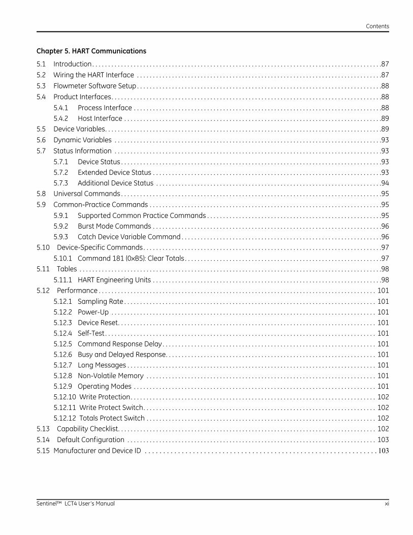
Chapter 5. HART Communications
5.1 Introduction . . . . . . . . . . . . . . . . . . . . . . . . . . . . . . . . . . . . . . . . . . . . . . . . . . . . . . . . . . . . . . . . . . . . . . . . . . . . . . . . . . . . . . . . . . .87
5.2 Wiring the HART Interface . . . . . . . . . . . . . . . . . . . . . . . . . . . . . . . . . . . . . . . . . . . . . . . . . . . . . . . . . . . . . . . . . . . . . . . . . . . . .87
5.3 Flowmeter Software Setup . . . . . . . . . . . . . . . . . . . . . . . . . . . . . . . . . . . . . . . . . . . . . . . . . . . . . . . . . . . . . . . . . . . . . . . . . . . . .88
5.4 Product Interfaces. . . . . . . . . . . . . . . . . . . . . . . . . . . . . . . . . . . . . . . . . . . . . . . . . . . . . . . . . . . . . . . . . . . . . . . . . . . . . . . . . . . . .88
5.4.1 Process Interface . . . . . . . . . . . . . . . . . . . . . . . . . . . . . . . . . . . . . . . . . . . . . . . . . . . . . . . . . . . . . . . . . . . . . . . . . . . . . .885.4.2 Host Interface . . . . . . . . . . . . . . . . . . . . . . . . . . . . . . . . . . . . . . . . . . . . . . . . . . . . . . . . . . . . . . . . . . . . . . . . . . . . . . . . .89
5.5 Device Variables. . . . . . . . . . . . . . . . . . . . . . . . . . . . . . . . . . . . . . . . . . . . . . . . . . . . . . . . . . . . . . . . . . . . . . . . . . . . . . . . . . . . . . .89
5.6 Dynamic Variables . . . . . . . . . . . . . . . . . . . . . . . . . . . . . . . . . . . . . . . . . . . . . . . . . . . . . . . . . . . . . . . . . . . . . . . . . . . . . . . . . . . .93
5.7 Status Information . . . . . . . . . . . . . . . . . . . . . . . . . . . . . . . . . . . . . . . . . . . . . . . . . . . . . . . . . . . . . . . . . . . . . . . . . . . . . . . . . . . .93
5.7.1 Device Status . . . . . . . . . . . . . . . . . . . . . . . . . . . . . . . . . . . . . . . . . . . . . . . . . . . . . . . . . . . . . . . . . . . . . . . . . . . . . . . . . .935.7.2 Extended Device Status . . . . . . . . . . . . . . . . . . . . . . . . . . . . . . . . . . . . . . . . . . . . . . . . . . . . . . . . . . . . . . . . . . . . . . . .935.7.3 Additional Device Status . . . . . . . . . . . . . . . . . . . . . . . . . . . . . . . . . . . . . . . . . . . . . . . . . . . . . . . . . . . . . . . . . . . . . . .94
5.8 Universal Commands . . . . . . . . . . . . . . . . . . . . . . . . . . . . . . . . . . . . . . . . . . . . . . . . . . . . . . . . . . . . . . . . . . . . . . . . . . . . . . . . . .95
5.9 Common-Practice Commands . . . . . . . . . . . . . . . . . . . . . . . . . . . . . . . . . . . . . . . . . . . . . . . . . . . . . . . . . . . . . . . . . . . . . . . . .95
5.9.1 Supported Common Practice Commands . . . . . . . . . . . . . . . . . . . . . . . . . . . . . . . . . . . . . . . . . . . . . . . . . . . . . . .955.9.2 Burst Mode Commands . . . . . . . . . . . . . . . . . . . . . . . . . . . . . . . . . . . . . . . . . . . . . . . . . . . . . . . . . . . . . . . . . . . . . . . .965.9.3 Catch Device Variable Command . . . . . . . . . . . . . . . . . . . . . . . . . . . . . . . . . . . . . . . . . . . . . . . . . . . . . . . . . . . . . . .96
5.10 Device-Specific Commands. . . . . . . . . . . . . . . . . . . . . . . . . . . . . . . . . . . . . . . . . . . . . . . . . . . . . . . . . . . . . . . . . . . . . . . . . . .97
5.10.1 Command 181 (0xB5): Clear Totals . . . . . . . . . . . . . . . . . . . . . . . . . . . . . . . . . . . . . . . . . . . . . . . . . . . . . . . . . . . . . .975.11 Tables . . . . . . . . . . . . . . . . . . . . . . . . . . . . . . . . . . . . . . . . . . . . . . . . . . . . . . . . . . . . . . . . . . . . . . . . . . . . . . . . . . . . . . . . . . . . . . .98
5.11.1 HART Engineering Units . . . . . . . . . . . . . . . . . . . . . . . . . . . . . . . . . . . . . . . . . . . . . . . . . . . . . . . . . . . . . . . . . . . . . . . .985.12 Performance . . . . . . . . . . . . . . . . . . . . . . . . . . . . . . . . . . . . . . . . . . . . . . . . . . . . . . . . . . . . . . . . . . . . . . . . . . . . . . . . . . . . . . . 101
5.12.1 Sampling Rate . . . . . . . . . . . . . . . . . . . . . . . . . . . . . . . . . . . . . . . . . . . . . . . . . . . . . . . . . . . . . . . . . . . . . . . . . . . . . . . 1015.12.2 Power-Up . . . . . . . . . . . . . . . . . . . . . . . . . . . . . . . . . . . . . . . . . . . . . . . . . . . . . . . . . . . . . . . . . . . . . . . . . . . . . . . . . . . 1015.12.3 Device Reset. . . . . . . . . . . . . . . . . . . . . . . . . . . . . . . . . . . . . . . . . . . . . . . . . . . . . . . . . . . . . . . . . . . . . . . . . . . . . . . . . 1015.12.4 Self-Test . . . . . . . . . . . . . . . . . . . . . . . . . . . . . . . . . . . . . . . . . . . . . . . . . . . . . . . . . . . . . . . . . . . . . . . . . . . . . . . . . . . . . 1015.12.5 Command Response Delay . . . . . . . . . . . . . . . . . . . . . . . . . . . . . . . . . . . . . . . . . . . . . . . . . . . . . . . . . . . . . . . . . . . 1015.12.6 Busy and Delayed Response. . . . . . . . . . . . . . . . . . . . . . . . . . . . . . . . . . . . . . . . . . . . . . . . . . . . . . . . . . . . . . . . . . 1015.12.7 Long Messages . . . . . . . . . . . . . . . . . . . . . . . . . . . . . . . . . . . . . . . . . . . . . . . . . . . . . . . . . . . . . . . . . . . . . . . . . . . . . . 1015.12.8 Non-Volatile Memory . . . . . . . . . . . . . . . . . . . . . . . . . . . . . . . . . . . . . . . . . . . . . . . . . . . . . . . . . . . . . . . . . . . . . . . . 1015.12.9 Operating Modes . . . . . . . . . . . . . . . . . . . . . . . . . . . . . . . . . . . . . . . . . . . . . . . . . . . . . . . . . . . . . . . . . . . . . . . . . . . . 1015.12.10 Write Protection. . . . . . . . . . . . . . . . . . . . . . . . . . . . . . . . . . . . . . . . . . . . . . . . . . . . . . . . . . . . . . . . . . . . . . . . . . . . . 1025.12.11 Write Protect Switch. . . . . . . . . . . . . . . . . . . . . . . . . . . . . . . . . . . . . . . . . . . . . . . . . . . . . . . . . . . . . . . . . . . . . . . . . 1025.12.12 Totals Protect Switch . . . . . . . . . . . . . . . . . . . . . . . . . . . . . . . . . . . . . . . . . . . . . . . . . . . . . . . . . . . . . . . . . . . . . . . . 102
5.13 Capability Checklist. . . . . . . . . . . . . . . . . . . . . . . . . . . . . . . . . . . . . . . . . . . . . . . . . . . . . . . . . . . . . . . . . . . . . . . . . . . . . . . . . 102
5.14 Default Configuration . . . . . . . . . . . . . . . . . . . . . . . . . . . . . . . . . . . . . . . . . . . . . . . . . . . . . . . . . . . . . . . . . . . . . . . . . . . . . . 103
5.15 Manufacturer and Device ID . . . . . . . . . . . . . . . . . . . . . . . . . . . . . . . . . . . . . . . . . . . . . . . . . . . . . . . . . . . . . . . 103
Sentinel™ LCT4 User’s Manual xi
Contents
Chapter 6. Maintenance
6.1 Calibration . . . . . . . . . . . . . . . . . . . . . . . . . . . . . . . . . . . . . . . . . . . . . . . . . . . . . . . . . . . . . . . . . . . . . . . . . . . . . . . . . . . . . . . . . . 105
6.1.1 Updating Sentinel LCT4 Instrument Software. . . . . . . . . . . . . . . . . . . . . . . . . . . . . . . . . . . . . . . . . . . . . . . . . . 1056.1.2 Checking the Meter Software. . . . . . . . . . . . . . . . . . . . . . . . . . . . . . . . . . . . . . . . . . . . . . . . . . . . . . . . . . . . . . . . . 1096.1.3 Trimming 4-20 mA Using the Keypad . . . . . . . . . . . . . . . . . . . . . . . . . . . . . . . . . . . . . . . . . . . . . . . . . . . . . . . . . 110
6.2 Hardware Maintenance and Inspection . . . . . . . . . . . . . . . . . . . . . . . . . . . . . . . . . . . . . . . . . . . . . . . . . . . . . . . . . . . . . . 111
6.2.1 Servicing the Pipe Flange Interface . . . . . . . . . . . . . . . . . . . . . . . . . . . . . . . . . . . . . . . . . . . . . . . . . . . . . . . . . . . 1126.2.2 Servicing the Sensor Ports or Transmitter Interface. . . . . . . . . . . . . . . . . . . . . . . . . . . . . . . . . . . . . . . . . . . . 112
6.3 Spare Parts . . . . . . . . . . . . . . . . . . . . . . . . . . . . . . . . . . . . . . . . . . . . . . . . . . . . . . . . . . . . . . . . . . . . . . . . . . . . . . . . . . . . . . . . . 114
6.4 Installing Replacement Parts. . . . . . . . . . . . . . . . . . . . . . . . . . . . . . . . . . . . . . . . . . . . . . . . . . . . . . . . . . . . . . . . . . . . . . . . . 114
xii Sentinel™ LCT4 User’s Manual
Contents
Chapter 7. Troubleshooting
7.1 Introduction . . . . . . . . . . . . . . . . . . . . . . . . . . . . . . . . . . . . . . . . . . . . . . . . . . . . . . . . . . . . . . . . . . . . . . . . . . . . . . . . . . . . . . . . . 115
7.2 Error Codes . . . . . . . . . . . . . . . . . . . . . . . . . . . . . . . . . . . . . . . . . . . . . . . . . . . . . . . . . . . . . . . . . . . . . . . . . . . . . . . . . . . . . . . . . 115
7.2.1 E0: No Error. . . . . . . . . . . . . . . . . . . . . . . . . . . . . . . . . . . . . . . . . . . . . . . . . . . . . . . . . . . . . . . . . . . . . . . . . . . . . . . . . . 1157.2.2 E1: Low Signal . . . . . . . . . . . . . . . . . . . . . . . . . . . . . . . . . . . . . . . . . . . . . . . . . . . . . . . . . . . . . . . . . . . . . . . . . . . . . . . 1157.2.3 E2: Soundspeed Error . . . . . . . . . . . . . . . . . . . . . . . . . . . . . . . . . . . . . . . . . . . . . . . . . . . . . . . . . . . . . . . . . . . . . . . . 1167.2.4 E3: Velocity Range Error . . . . . . . . . . . . . . . . . . . . . . . . . . . . . . . . . . . . . . . . . . . . . . . . . . . . . . . . . . . . . . . . . . . . . . 1167.2.5 E4: Signal Quality Error . . . . . . . . . . . . . . . . . . . . . . . . . . . . . . . . . . . . . . . . . . . . . . . . . . . . . . . . . . . . . . . . . . . . . . . 1167.2.6 E5: Amplitude Error . . . . . . . . . . . . . . . . . . . . . . . . . . . . . . . . . . . . . . . . . . . . . . . . . . . . . . . . . . . . . . . . . . . . . . . . . . 1167.2.7 E6: Cycle Skip, Acceleration Error . . . . . . . . . . . . . . . . . . . . . . . . . . . . . . . . . . . . . . . . . . . . . . . . . . . . . . . . . . . . . 1167.2.8 E7: Analog Output Error . . . . . . . . . . . . . . . . . . . . . . . . . . . . . . . . . . . . . . . . . . . . . . . . . . . . . . . . . . . . . . . . . . . . . . 1177.2.9 E13: Settle Tracking AGC . . . . . . . . . . . . . . . . . . . . . . . . . . . . . . . . . . . . . . . . . . . . . . . . . . . . . . . . . . . . . . . . . . . . . 1177.2.10 E14: Tracking Seek Mode . . . . . . . . . . . . . . . . . . . . . . . . . . . . . . . . . . . . . . . . . . . . . . . . . . . . . . . . . . . . . . . . . . . . . 1177.2.11 E15: Active Tw Error . . . . . . . . . . . . . . . . . . . . . . . . . . . . . . . . . . . . . . . . . . . . . . . . . . . . . . . . . . . . . . . . . . . . . . . . . . 1177.2.12 E16: Totalizer Overflow Error. . . . . . . . . . . . . . . . . . . . . . . . . . . . . . . . . . . . . . . . . . . . . . . . . . . . . . . . . . . . . . . . . . 1177.2.13 E17: Temperature Input Error . . . . . . . . . . . . . . . . . . . . . . . . . . . . . . . . . . . . . . . . . . . . . . . . . . . . . . . . . . . . . . . . . 1177.2.14 E18: Pressure Input Error . . . . . . . . . . . . . . . . . . . . . . . . . . . . . . . . . . . . . . . . . . . . . . . . . . . . . . . . . . . . . . . . . . . . . 1187.2.15 E19: Density Input Error . . . . . . . . . . . . . . . . . . . . . . . . . . . . . . . . . . . . . . . . . . . . . . . . . . . . . . . . . . . . . . . . . . . . . . 1187.2.16 E20: Special Input Error. . . . . . . . . . . . . . . . . . . . . . . . . . . . . . . . . . . . . . . . . . . . . . . . . . . . . . . . . . . . . . . . . . . . . . . 1187.2.17 E21: API Error . . . . . . . . . . . . . . . . . . . . . . . . . . . . . . . . . . . . . . . . . . . . . . . . . . . . . . . . . . . . . . . . . . . . . . . . . . . . . . . . 1187.2.18 E22: Degraded Performance Error . . . . . . . . . . . . . . . . . . . . . . . . . . . . . . . . . . . . . . . . . . . . . . . . . . . . . . . . . . . . 1187.2.19 E23: Reduced Accuracy Error . . . . . . . . . . . . . . . . . . . . . . . . . . . . . . . . . . . . . . . . . . . . . . . . . . . . . . . . . . . . . . . . 1187.2.20 E24: Low SNR Error . . . . . . . . . . . . . . . . . . . . . . . . . . . . . . . . . . . . . . . . . . . . . . . . . . . . . . . . . . . . . . . . . . . . . . . . . . 1197.2.21 E29: Stale Data Error . . . . . . . . . . . . . . . . . . . . . . . . . . . . . . . . . . . . . . . . . . . . . . . . . . . . . . . . . . . . . . . . . . . . . . . . 1197.2.22 E30: Channel Disabled . . . . . . . . . . . . . . . . . . . . . . . . . . . . . . . . . . . . . . . . . . . . . . . . . . . . . . . . . . . . . . . . . . . . . . . 119
7.3 Displaying Diagnostic Parameters. . . . . . . . . . . . . . . . . . . . . . . . . . . . . . . . . . . . . . . . . . . . . . . . . . . . . . . . . . . . . . . . . . . . 120
7.4 Fluid and Pipe Problems . . . . . . . . . . . . . . . . . . . . . . . . . . . . . . . . . . . . . . . . . . . . . . . . . . . . . . . . . . . . . . . . . . . . . . . . . . . . . 123
7.4.1 Fluid Problems . . . . . . . . . . . . . . . . . . . . . . . . . . . . . . . . . . . . . . . . . . . . . . . . . . . . . . . . . . . . . . . . . . . . . . . . . . . . . . . 1237.4.2 Pipe Problems . . . . . . . . . . . . . . . . . . . . . . . . . . . . . . . . . . . . . . . . . . . . . . . . . . . . . . . . . . . . . . . . . . . . . . . . . . . . . . . 124
7.5 Transducer Problems . . . . . . . . . . . . . . . . . . . . . . . . . . . . . . . . . . . . . . . . . . . . . . . . . . . . . . . . . . . . . . . . . . . . . . . . . . . . . . . . 124
7.6 Audit Trail . . . . . . . . . . . . . . . . . . . . . . . . . . . . . . . . . . . . . . . . . . . . . . . . . . . . . . . . . . . . . . . . . . . . . . . . . . . . . . . . . . . . . . . . . . . 125
7.6.1 Audit Log . . . . . . . . . . . . . . . . . . . . . . . . . . . . . . . . . . . . . . . . . . . . . . . . . . . . . . . . . . . . . . . . . . . . . . . . . . . . . . . . . . . . 1257.6.2 Reading Audit Log Records . . . . . . . . . . . . . . . . . . . . . . . . . . . . . . . . . . . . . . . . . . . . . . . . . . . . . . . . . . . . . . . . . . . 1277.6.3 Formatting and Viewing Log Records . . . . . . . . . . . . . . . . . . . . . . . . . . . . . . . . . . . . . . . . . . . . . . . . . . . . . . . . . 128
7.7 Uncertainty in Flow Rate for a Non-Insulated Meter . . . . . . . . . . . . . . . . . . . . . . . . . . . . . . . . . . . . . . . . . . . . . . . . . . . 129
Appendix A. Menu Maps
Appendix B. CE Mark Compliance and High Noise Areas
B.1 Introduction . . . . . . . . . . . . . . . . . . . . . . . . . . . . . . . . . . . . . . . . . . . . . . . . . . . . . . . . . . . . . . . . . . . . . . . . . . . . . . . . . . . . . . . . . 141
B.2 EMC Compliance . . . . . . . . . . . . . . . . . . . . . . . . . . . . . . . . . . . . . . . . . . . . . . . . . . . . . . . . . . . . . . . . . . . . . . . . . . . . . . . . . . . . 141
Sentinel™ LCT4 User’s Manual xiii

Contents
Appendix C. Service Record
C.1 Introduction. . . . . . . . . . . . . . . . . . . . . . . . . . . . . . . . . . . . . . . . . . . . . . . . . . . . . . . . . . . . . . . . . . . . . . . . . . . . . . . . . . . . . . . . . 143
C.2 Data Entry . . . . . . . . . . . . . . . . . . . . . . . . . . . . . . . . . . . . . . . . . . . . . . . . . . . . . . . . . . . . . . . . . . . . . . . . . . . . . . . . . . . . . . . . . . 143
xiv Sentinel™ LCT4 User’s Manual
Chapter 1. Features and Capabilities
Chapter 1. Features and Capabilities
1.1 Overview
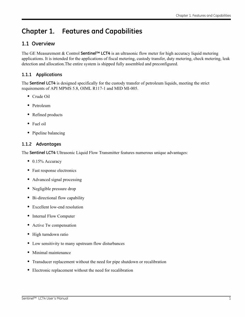
The GE Measurement & Control Sentinel™ LCT4 is an ultrasonic flow meter for high accuracy liquid metering applications. It is intended for the applications of fiscal metering, custody transfer, duty metering, check metering, leak detection and allocation.The entire system is shipped fully assembled and preconfigured.
1.1.1 Applications
The Sentinel LCT4 is designed specifically for the custody transfer of petroleum liquids, meeting the strict requirements of API MPMS 5.8, OIML R117-1 and MID MI-005.
• Crude Oil
• Petroleum
• Refined products
• Fuel oil
• Pipeline balancing
1.1.2 Advantages
The Sentinel LCT4 Ultrasonic Liquid Flow Transmitter features numerous unique advantages:
• 0.15% Accuracy
• Fast response electronics
• Advanced signal processing
• Negligible pressure drop
• Bi-directional flow capability
• Excellent low-end resolution
• Internal Flow Computer
• Active Tw compensation
• High turndown ratio
• Low sensitivity to many upstream flow disturbances
• Minimal maintenance
• Transducer replacement without the need for pipe shutdown or recalibration
• Electronic replacement without the need for recalibration
Sentinel™ LCT4 User’s Manual 1
Chapter 1. Features and Capabilities
1.1.3 Meter Components
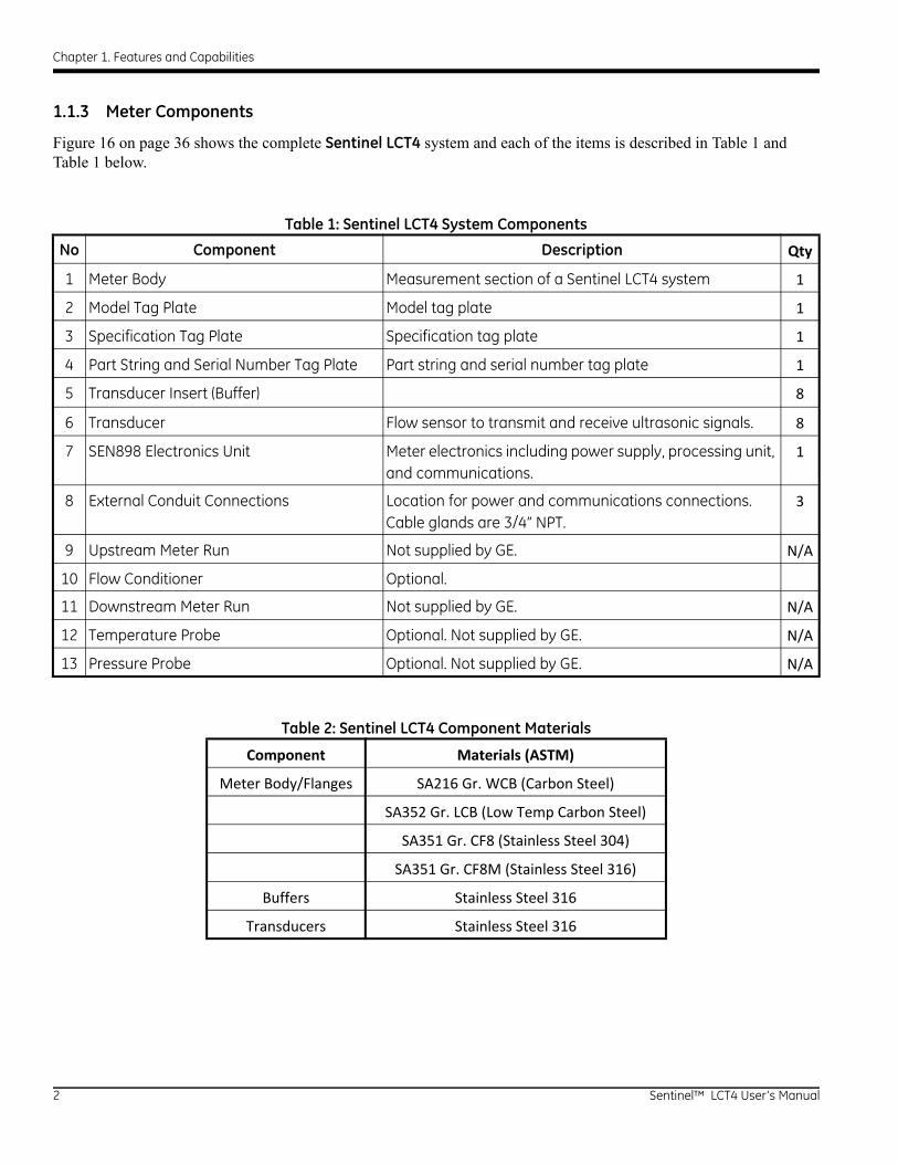
Figure 16 on page 36 shows the complete Sentinel LCT4 system and each of the items is described in Table 1 and Table 1 below.
Table 1: Sentinel LCT4 System Components
No Component Description Qty
1 Meter Body Measurement section of a Sentinel LCT4 system 1
2 Model Tag Plate Model tag plate 1
3 Specification Tag Plate Specification tag plate 1
4 Part String and Serial Number Tag Plate Part string and serial number tag plate 1
5 Transducer Insert (Buffer) 8
6 Transducer Flow sensor to transmit and receive ultrasonic signals. 8
7 SEN898 Electronics Unit Meter electronics including power supply, processing unit, and communications.
1
8 External Conduit Connections Location for power and communications connections. Cable glands are 3/4” NPT.
3
9 Upstream Meter Run Not supplied by GE. N/A
10 Flow Conditioner Optional.
11 Downstream Meter Run Not supplied by GE. N/A
12 Temperature Probe Optional. Not supplied by GE. N/A
13 Pressure Probe Optional. Not supplied by GE. N/A
Table 2: Sentinel LCT4 Component Materials
Component Materials (ASTM)
Meter Body/Flanges SA216 Gr. WCB (Carbon Steel)
SA352 Gr. LCB (Low Temp Carbon Steel)
SA351 Gr. CF8 (Stainless Steel 304)
SA351 Gr. CF8M (Stainless Steel 316)
Buffers Stainless Steel 316
Transducers Stainless Steel 316
2 Sentinel™ LCT4 User’s Manual
Chapter 1. Features and Capabilities
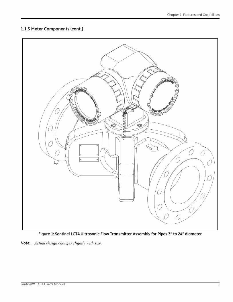
1.1.3 Meter Components (cont.)
Figure 1: Sentinel LCT4 Ultrasonic Flow Transmitter Assembly for Pipes 3” to 24” diameter
Note: Actual design changes slightly with size.
Sentinel™ LCT4 User’s Manual 3
Chapter 1. Features and Capabilities
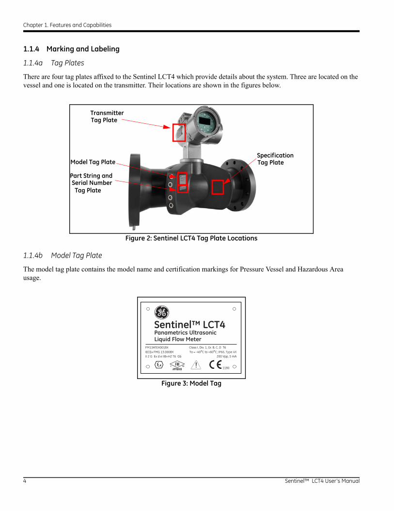
1.1.4 Marking and Labeling
1.1.4a Tag Plates
There are four tag plates affixed to the Sentinel LCT4 which provide details about the system. Three are located on the vessel and one is located on the transmitter. Their locations are shown in the figures below.
Figure 2: Sentinel LCT4 Tag Plate Locations
1.1.4b Model Tag Plate
The model tag plate contains the model name and certification markings for Pressure Vessel and Hazardous Area usage.
Figure 3: Model Tag
TransmitterTag Plate
Model Tag Plate
Part String andSerial Number
SpecificationTag Plate
Tag Plate
Sentinel™ LCT4Panametrics UltrasonicLiquid Flow Meter
FM13ATEX0018XIECEx FMG 13.0008X
Class I, Div. 1, Gr. B, C, D T6
1180QII 2 G Ex d e IIB+H2 T6 Gb
Ta = -40°C to +60°C; IP66, Type 4X200 Vpp, 5 mA
!
4 Sentinel™ LCT4 User’s Manual
Chapter 1. Features and Capabilities
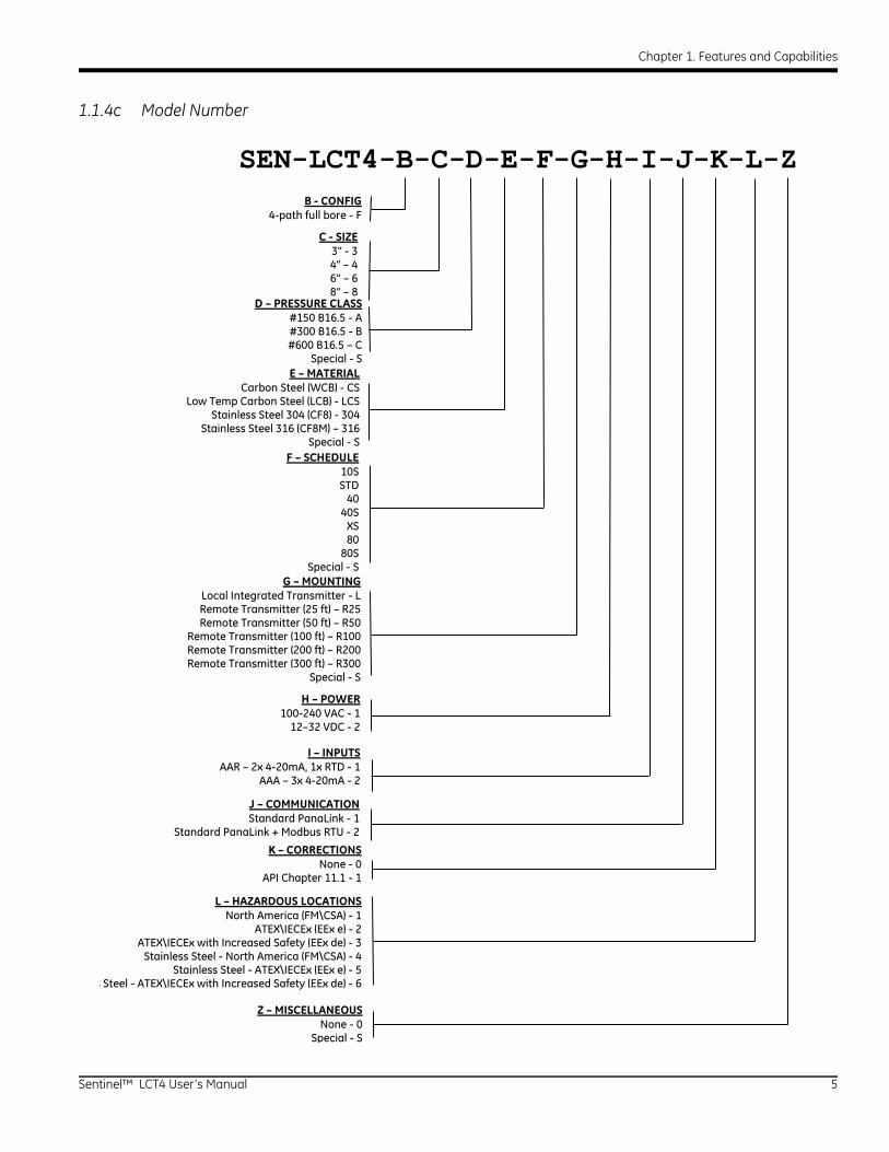
1.1.4c Model Number
SEN-LCT4-B-C-D-E-F-G-H-I-J-K-L-ZB - CONFIG
4-path full bore - F
C - SIZE3” - 34” – 46” – 68” – 8
D – PRESSURE CLASS#150 B16.5 - A#300 B16.5 - B#600 B16.5 – C
Special - SE – MATERIAL
Carbon Steel (WCB) - CSLow Temp Carbon Steel (LCB) - LCS
Stainless Steel 304 (CF8) - 304Stainless Steel 316 (CF8M) – 316
Special - SF – SCHEDULE
10SSTD
4040S
XS80
80S Special - S
G – MOUNTINGLocal Integrated Transmitter - LRemote Transmitter (25 ft) – R25Remote Transmitter (50 ft) – R50
Remote Transmitter (100 ft) – R100Remote Transmitter (200 ft) – R200Remote Transmitter (300 ft) – R300
Special - S
H – POWER100-240 VAC - 1
12–32 VDC - 2
I – INPUTSAAR – 2x 4-20mA, 1x RTD - 1
AAA – 3x 4-20mA - 2
J – COMMUNICATIONStandard PanaLink - 1
Standard PanaLink + Modbus RTU - 2
K – CORRECTIONSNone - 0
API Chapter 11.1 - 1
L – HAZARDOUS LOCATIONSNorth America (FM\CSA) - 1
ATEX\IECEx (EEx e) - 2 ATEX\IECEx with Increased Safety (EEx de) - 3
Stainless Steel - North America (FM\CSA) - 4Stainless Steel - ATEX\IECEx (EEx e) - 5
s Steel - ATEX\IECEx with Increased Safety (EEx de) - 6
Z – MISCELLANEOUS None - 0
Special - S
Sentinel™ LCT4 User’s Manual 5
Chapter 1. Features and Capabilities
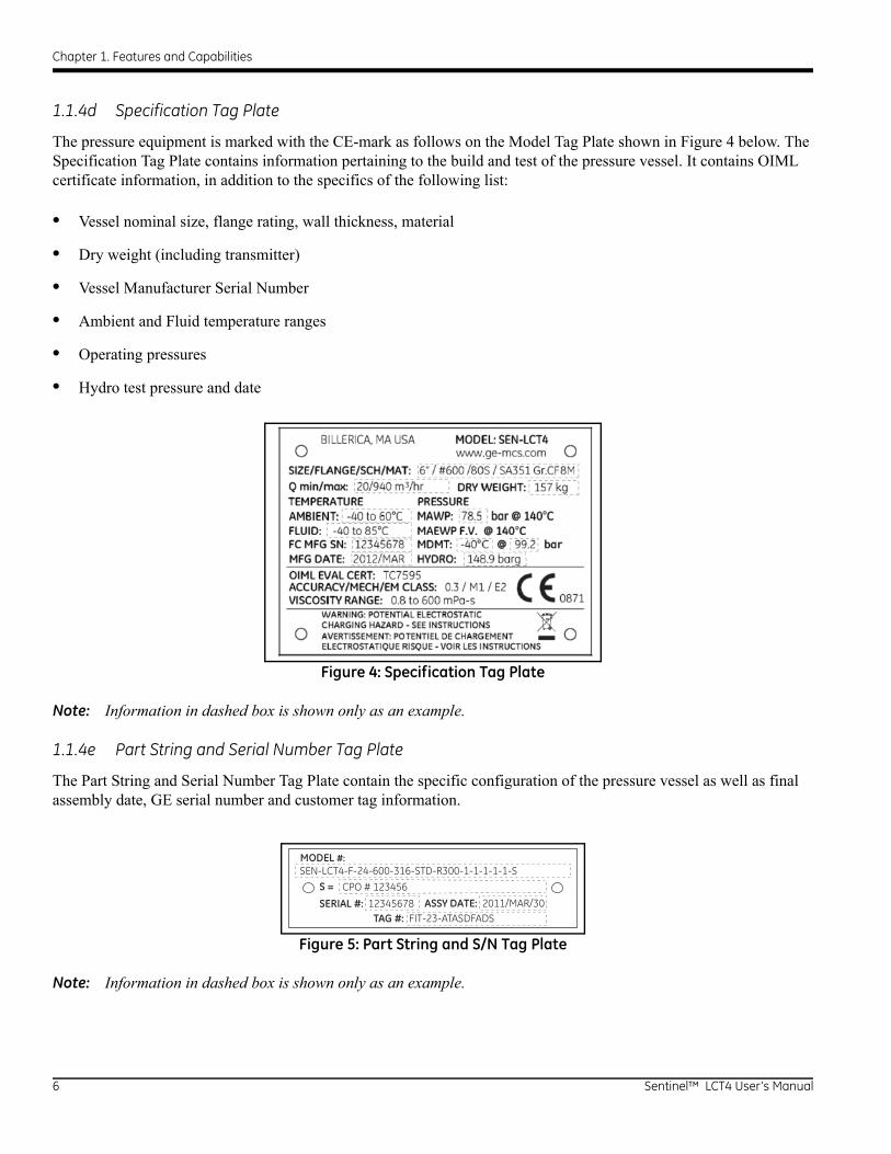
1.1.4d Specification Tag Plate
The pressure equipment is marked with the CE-mark as follows on the Model Tag Plate shown in Figure 4 below. The Specification Tag Plate contains information pertaining to the build and test of the pressure vessel. It contains OIML certificate information, in addition to the specifics of the following list:
• Vessel nominal size, flange rating, wall thickness, material
• Dry weight (including transmitter)
• Vessel Manufacturer Serial Number
• Ambient and Fluid temperature ranges
• Operating pressures
• Hydro test pressure and date
Figure 4: Specification Tag Plate
Note: Information in dashed box is shown only as an example.
1.1.4e Part String and Serial Number Tag Plate
The Part String and Serial Number Tag Plate contain the specific configuration of the pressure vessel as well as final assembly date, GE serial number and customer tag information.
Figure 5: Part String and S/N Tag Plate
Note: Information in dashed box is shown only as an example.
TAG #: FIT-23-ATASDFADS
MODEL #:
SEN-LCT4-F-24-600-316-STD-R300-1-1-1-1-1-S
SERIAL #: 12345678 ASSY DATE: 2011/MAR/30
S = CPO # 123456
6 Sentinel™ LCT4 User’s Manual
Chapter 1. Features and Capabilities
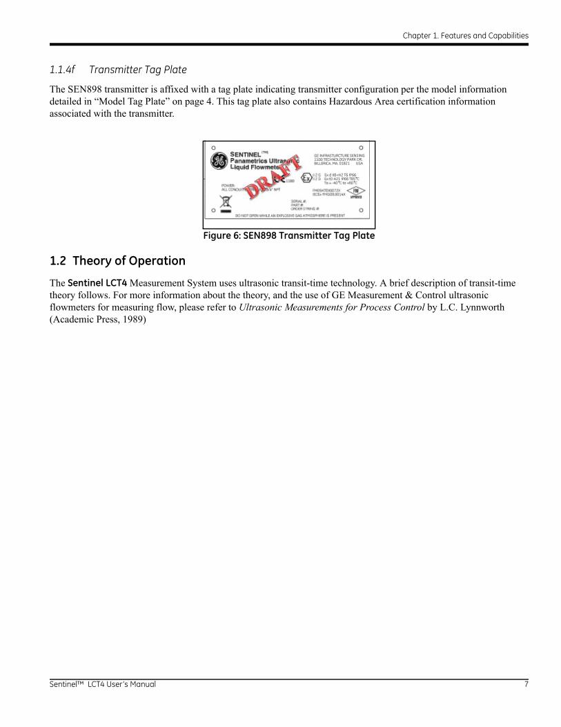
1.1.4f Transmitter Tag Plate
The SEN898 transmitter is affixed with a tag plate indicating transmitter configuration per the model information detailed in “Model Tag Plate” on page 4. This tag plate also contains Hazardous Area certification information associated with the transmitter.
Figure 6: SEN898 Transmitter Tag Plate
1.2 Theory of Operation
The Sentinel LCT4 Measurement System uses ultrasonic transit-time technology. A brief description of transit-time theory follows. For more information about the theory, and the use of GE Measurement & Control ultrasonic flowmeters for measuring flow, please refer to Ultrasonic Measurements for Process Control by L.C. Lynnworth (Academic Press, 1989)
Sentinel™ LCT4 User’s Manual 7

Chapter 1. Features and Capabilities
1.2.1 Transit-Time Method
The transit time technique uses a pair of transducers, with each transducer alternately sending and receiving coded ultrasonic signals through the fluid. When the fluid is flowing, signal transit time in the downstream direction is shorter than in the upstream direction; the difference between these transit times is proportional to the flow velocity. The Sentinel LCT4 measures this very small time difference and, using various digital signal processing techniques combined with programmed pipe parameters, determines the flow rate and direction.
1.2.2 Transducers
When in a transmit cycle, transducers convert electrical energy into ultrasonic pulses and then convert the ultrasonic pulses back to electrical energy when in a receive cycle. In other words, they act like loudspeakers when transmitting the signal and like microphones when receiving it. They perform the actual data transmission and collection, thus interrogating the flow.
The transducers in the Sentinel LCT4 Measurement System were specifically designed to be replaced under operating conditions. In the event that a transducer becomes damaged or non-functional, it can be replaced without shutting down the pipeline. Recalibration of the replacement is not necessary.
8 Sentinel™ LCT4 User’s Manual
Chapter 1. Features and Capabilities
1.2.3 Multipath Design
Multipath ultrasonic flowmeters are designed with more than one pair of transducers to interrogate the flow field in different locations and more accurately determine the actual flowrate. The Sentinel LCT4 Measurement System uses four measurement locations. These measurement paths are located across the meter body and tilted at an angle. The four measurement paths are orthogonal to each other.
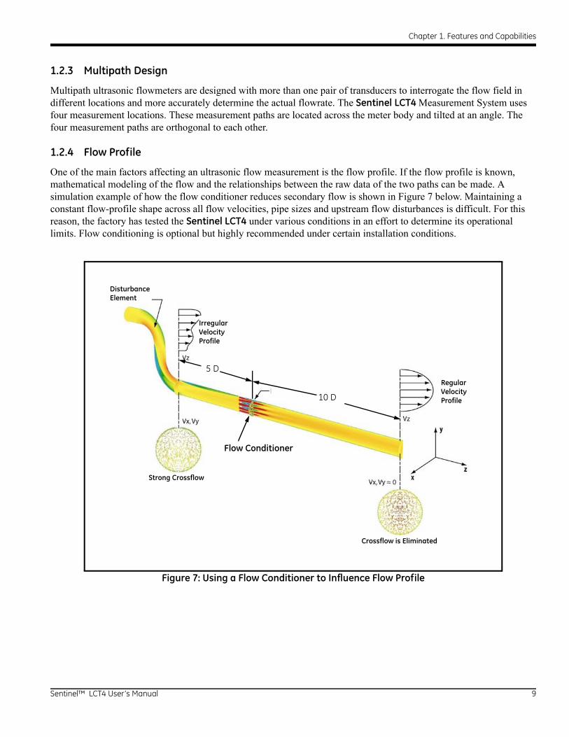
1.2.4 Flow Profile
One of the main factors affecting an ultrasonic flow measurement is the flow profile. If the flow profile is known, mathematical modeling of the flow and the relationships between the raw data of the two paths can be made. A simulation example of how the flow conditioner reduces secondary flow is shown in Figure 7 below. Maintaining a constant flow-profile shape across all flow velocities, pipe sizes and upstream flow disturbances is difficult. For this reason, the factory has tested the Sentinel LCT4 under various conditions in an effort to determine its operational limits. Flow conditioning is optional but highly recommended under certain installation conditions.
Figure 7: Using a Flow Conditioner to Influence Flow Profile
DisturbanceElement
IrregularVelocityProfile
RegularVelocityProfile
Strong Crossflow
Crossflow is Eliminated
Flow Conditioner
5 D
10 D
Sentinel™ LCT4 User’s Manual 9
Chapter 1. Features and Capabilities
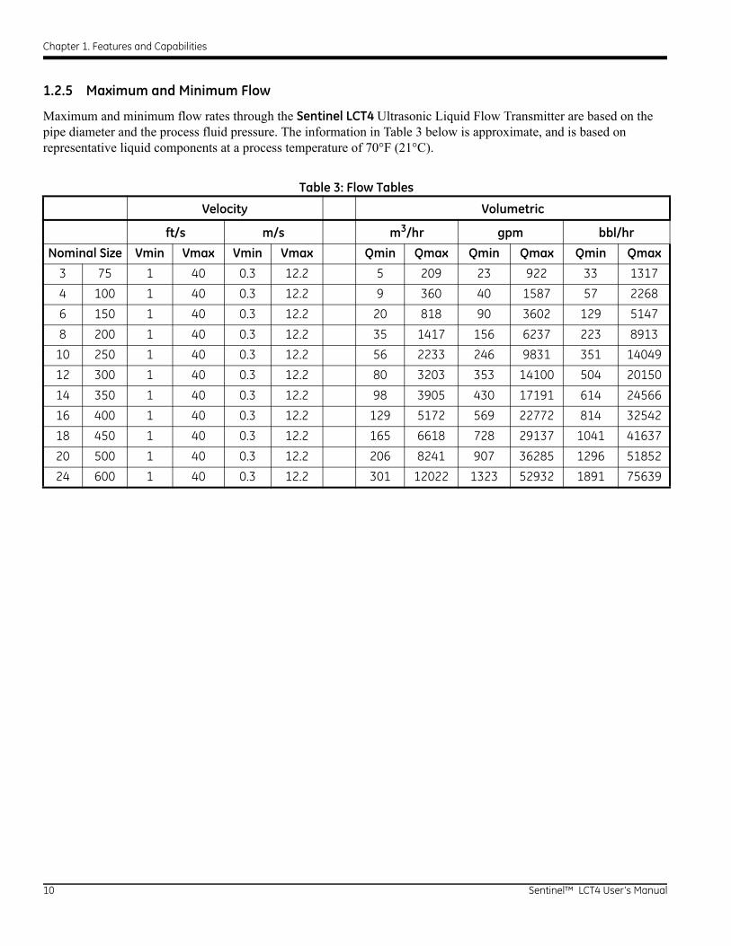
1.2.5 Maximum and Minimum Flow
Maximum and minimum flow rates through the Sentinel LCT4 Ultrasonic Liquid Flow Transmitter are based on the pipe diameter and the process fluid pressure. The information in Table 3 below is approximate, and is based on representative liquid components at a process temperature of 70°F (21°C).
Table 3: Flow Tables
Velocity Volumetric
ft/s m/s m3/hr gpm bbl/hr
Nominal Size Vmin Vmax Vmin Vmax Qmin Qmax Qmin Qmax Qmin Qmax
3 75 1 40 0.3 12.2 5 209 23 922 33 1317
4 100 1 40 0.3 12.2 9 360 40 1587 57 2268
6 150 1 40 0.3 12.2 20 818 90 3602 129 5147
8 200 1 40 0.3 12.2 35 1417 156 6237 223 8913
10 250 1 40 0.3 12.2 56 2233 246 9831 351 14049
12 300 1 40 0.3 12.2 80 3203 353 14100 504 20150
14 350 1 40 0.3 12.2 98 3905 430 17191 614 24566
16 400 1 40 0.3 12.2 129 5172 569 22772 814 32542
18 450 1 40 0.3 12.2 165 6618 728 29137 1041 41637
20 500 1 40 0.3 12.2 206 8241 907 36285 1296 51852
24 600 1 40 0.3 12.2 301 12022 1323 52932 1891 75639
10 Sentinel™ LCT4 User’s Manual

Chapter 1. Features and Capabilities
1.3 Specifications
The system specifications for the Sentinel LCT4 Ultrasonic Liquid Flow Transmitter are divided into the following categories:
1.3.1 Operation and Performance
Note: The Sentinel LCT4 has been designed to meet the OIML R117-1, MID MI-005 and API MPMS 5.8 requirements.
1.3.1a Fluid Types
Liquid hydrocarbons, crude and refined products, other liquids.
1.3.1b Flow Measurement
Correlation Transit Time mode
1.3.1c Linearity
±0.15% of measured volume for flow rates between 1 and 33 ft/s (0.3 and 10 m/s)
Note: Higher flow rates are possible. Consult the factory.
1.3.1d Accuracy
< ± 0.15% of measured volume for flow rates between 3 and 30 ft/s.
1.3.1e Uncertainty
< ±0.027% according to API MPMS 5.8
1.3.1f Zero Stability
< 0.003 ft/s
1.3.1g Viscosity Range
0 to 660 cStConsult factory for higher Reynolds numbers.
1.3.1h Reynolds Range
Re >10,000Consult factory for lower Reynolds numbers.
1.3.1i Process Temperature
–40° to +140°C (–40° to +284°F) Standard(Remote mount required above 85°C (185°F).
Sentinel™ LCT4 User’s Manual 11
Chapter 1. Features and Capabilities
1.3.1j Ambient Temperature
–40° to +60°C (–40° to +140°F)
1.3.1k Storage Temperature
–40° to +85°C (-40 to +176°C)
1.3.2 Meter Body
1.3.2a Path Configuration
4 path Gaussian Quadrature
1.3.2b Meter Body Materials
• Carbon steel SA216 Gr. WCB
• Low temperature carbon steel SA352 Gr. LCB
• Stainless steel SA351 Gr. CF8
• Stainless steel SA351 Gr. CF8M
Others on request.
1.3.2c Flowcells
3” (75 mm) to 24” (600 mm)
Others on request.
12 Sentinel™ LCT4 User’s Manual

Chapter 1. Features and Capabilities
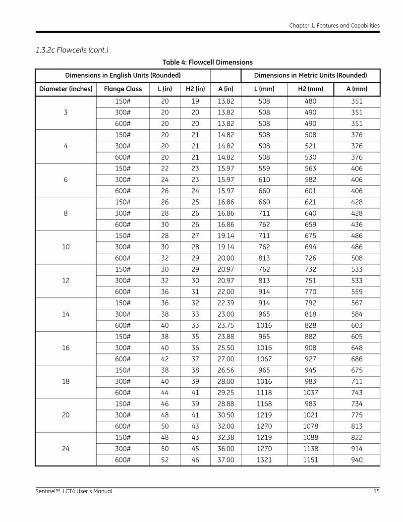
1.3.2c Flowcells (cont.)
Figure 8: Flowcell Assembly for Sentinel LCT4 with 3” and 4” Pipes
Sentinel™ LCT4 User’s Manual 13

Chapter 1. Features and Capabilities
Figure 9: Flowcell Assembly for Sentinel LCT4 with 6” to 24” Pipes
Note: Use Figures 8 and 9 to identify L, H2 and A measurements in Table 4 on page 15. The A dimension is the MAX depth of the system. Dimensional extremes as depicted depend on the actual meter and flange size.
14 Sentinel™ LCT4 User’s Manual
Chapter 1. Features and Capabilities
1.3.2c Flowcells (cont.)
Table 4: Flowcell Dimensions
Dimensions in English Units (Rounded) Dimensions in Metric Units (Rounded)
Diameter (inches) Flange Class L (in) H2 (in) A (in) L (mm) H2 (mm) A (mm)
150# 20 19 13.82 508 480 351
3 300# 20 20 13.82 508 490 351
600# 20 20 13.82 508 490 351
150# 20 21 14.82 508 508 376
4 300# 20 21 14.82 508 521 376
600# 20 21 14.82 508 530 376
150# 22 23 15.97 559 563 406
6 300# 24 23 15.97 610 582 406
600# 26 24 15.97 660 601 406
150# 26 25 16.86 660 621 428
8 300# 28 26 16.86 711 640 428
600# 30 26 16.86 762 659 436
150# 28 27 19.14 711 675 486
10 300# 30 28 19.14 762 694 486
600# 32 29 20.00 813 726 508
150# 30 29 20.97 762 732 533
12 300# 32 30 20.97 813 751 533
600# 36 31 22.00 914 770 559
150# 36 32 22.39 914 792 567
14 300# 38 33 23.00 965 818 584
600# 40 33 23.75 1016 828 603
150# 38 35 23.88 965 882 605
16 300# 40 36 25.50 1016 908 648
600# 42 37 27.00 1067 927 686
150# 38 38 26.56 965 945 675
18 300# 40 39 28.00 1016 983 711
600# 44 41 29.25 1118 1037 743
150# 46 39 28.88 1168 983 734
20 300# 48 41 30.50 1219 1021 775
600# 50 43 32.00 1270 1078 813
150# 48 43 32.38 1219 1088 822
24 300# 50 45 36.00 1270 1138 914
600# 52 46 37.00 1321 1151 940
Sentinel™ LCT4 User’s Manual 15

Chapter 1. Features and Capabilities
1.3.2d Flange Ratings
• 150 #
• 300 #
• 600#
Others on request.
1.3.2e Pipe Schedules
• 40S
• STD
• 80S
• 10S
• XS
Others on request.
1.3.2f PED Compliance
• PED Cat II, Module B + C1
1.3.2g Installation Requirement
The meter must be installed with 20D straight piping upstream and 5D straight piping downstream. Inlet and outlet piping shall match the meter ID within 0.5%. In case a 20D inlet cannot be mounted, a 10D inlet with flow conditioned could be applied. Pressure, temperature and density connections must be located in the downstream piping. The upstream piping and flow conditioner) must be free of items that could disturb the flow profile.
16 Sentinel™ LCT4 User’s Manual
Chapter 1. Features and Capabilities
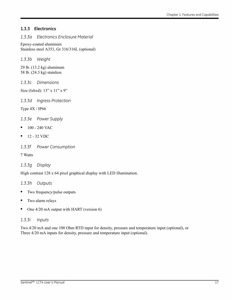
1.3.3 Electronics
1.3.3a Electronics Enclosure Material
Epoxy-coated aluminumStainless steel A351, Gr 316/316L (optional)
1.3.3b Weight
29 lb. (13.2 kg) aluminum58 lb. (24.3 kg) stainless
1.3.3c Dimensions
Size (lxhxd): 13” x 11” x 9”
1.3.3d Ingress Protection
Type 4X / IP66
1.3.3e Power Supply
• 100 - 240 VAC
• 12 - 32 VDC
1.3.3f Power Consumption
7 Watts
1.3.3g Display
High contrast 128 x 64 pixel graphical display with LED illumination.
1.3.3h Outputs
• Two frequency/pulse outputs
• Two alarm relays
• One 4/20 mA output with HART (version 6)
1.3.3i Inputs
Two 4/20 mA and one 100 Ohm RTD input for density, pressure and temperature input (optional), orThree 4/20 mA inputs for density, pressure and temperature input (optional).
Sentinel™ LCT4 User’s Manual 17

Chapter 1. Features and Capabilities
1.3.3j Digital Interfaces
• HART over 4/20 mA output (version 6)
• PanaLink over RS232/485/USB
• Modbus over RS232/485 (optional)
1.3.3k Flow Computer Functionality
Integrated flow computer with full P and T volume corrections according to API 11.1
1.3.3l Hazardous Area Classification
• USA/Canada: Class I, Division 1, Groups B, C, D T6
• Europe/International: II 2 G Ex d e IIB+H2 T6 Gb
• Ta = -40°C to +60°C
1.3.3m CE Compliance
• 2004/108/EC
• 2006/95/EC LVD
1.3.4 Custody Transfer Approvals
1.3.4a USA / Canada
Compliant with API MPMS 5.8
1.3.4b Europe
MID MI-005
1.3.4c Rest of World
OIML R117-1 Accuracy Class 0.3
Note: The Custody Transfer approvals are valid for the flowmeter only. These approvals are not applicable for the built-in flow computer.
18 Sentinel™ LCT4 User’s Manual

Chapter 1. Features and Capabilities
1.3.5 Standards
The Sentinel LCT4 has been designed in accordance with the following standards:
• ASME B31.3
• ASME Section IX
• ASME B16.5
• ANSI/NACE MR0175/ISO 15156 AND NACE MR0103
• ANSI/NACE B.1.20.1
• ASME B36.10M and B36.19M
• EN 10204, TYPE 3.1
1.4 Maximum Allowable Operating Data
1.4.1 Operating and Storage Temperatures
Process Fluid Operating Temperature: -40 to +140°C (-40 to +284°F)
Ambient Operating Temperature: -40 to +60°C (-40 to +140°F) - electronics and pressure vessel
Storage Temperature: -40 to +85°C (-40 to +185°F) - electronics and pressure vessel
Note: Remote Mount electronics are required when Process Fluid Temperature exceeds +85°C (185°F).
1.4.2 Operating Pressures
Maximum operating pressures specified are listed in Table 5 below by material and pressure class.
Table 5: Maximum Operating Pressures by Material and Pressure ClassMaximum Operating Pressures, English (psi g)
WCB LCB CF8 CF8M
Flange Class 100°F 284°F 100°F 284°F 100°F 284°F 100°F 284°F
150# 285 235 265 234 275 209 275 218
300# 740 659 695 643 720 550 720 570
600# 1480 1316 1395 1282 1440 1095 1440 1139
Maximum Operating Pressures, Metric (bar g)
WCB LCB CF8 CF8M
Flange Class 38°C 140°C 38°C 140°C 38°C 140°C 38°C 140°C
150# 19.6 16.2 18.3 16.1 19.0 14.4 19.0 15.0
300# 51.0 45.4 47.9 44.3 49.6 37.9 49.6 39.3
600# 102.0 90.7 96.1 88.4 99.2 75.5 99.2 78.5
Sentinel™ LCT4 User’s Manual 19
Chapter 1. Features and Capabilities
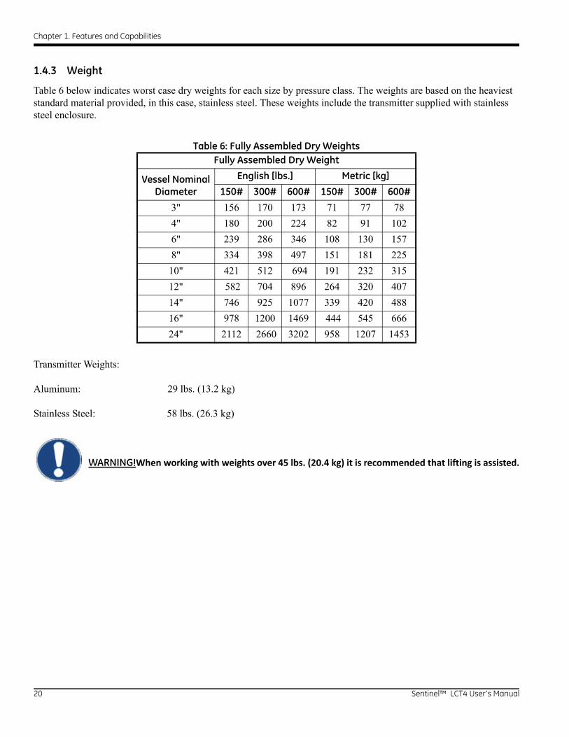
1.4.3 Weight
Table 6 below indicates worst case dry weights for each size by pressure class. The weights are based on the heaviest standard material provided, in this case, stainless steel. These weights include the transmitter supplied with stainless steel enclosure.
Transmitter Weights:
Aluminum: 29 lbs. (13.2 kg)
Stainless Steel: 58 lbs. (26.3 kg)
WARNING!When working with weights over 45 lbs. (20.4 kg) it is recommended that lifting is assisted.
Table 6: Fully Assembled Dry WeightsFully Assembled Dry Weight
Vessel Nominal Diameter
English [lbs.] Metric [kg]
150# 300# 600# 150# 300# 600#
3" 156 170 173 71 77 78
4" 180 200 224 82 91 102
6" 239 286 346 108 130 157
8" 334 398 497 151 181 225
10" 421 512 694 191 232 315
12" 582 704 896 264 320 407
14" 746 925 1077 339 420 488
16" 978 1200 1469 444 545 666
24" 2112 2660 3202 958 1207 1453
20 Sentinel™ LCT4 User’s Manual
Chapter 1. Features and Capabilities
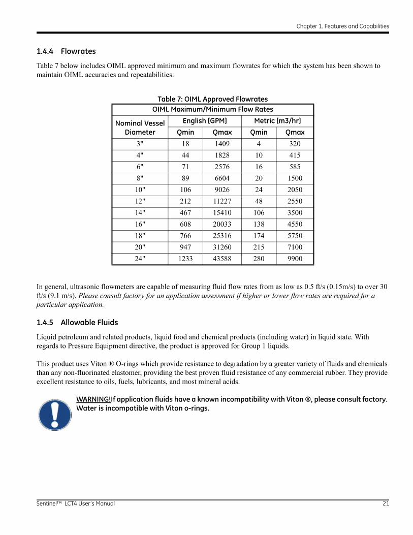
1.4.4 Flowrates
Table 7 below includes OIML approved minimum and maximum flowrates for which the system has been shown to maintain OIML accuracies and repeatabilities.
In general, ultrasonic flowmeters are capable of measuring fluid flow rates from as low as 0.5 ft/s (0.15m/s) to over 30 ft/s (9.1 m/s). Please consult factory for an application assessment if higher or lower flow rates are required for a particular application.
1.4.5 Allowable Fluids
Liquid petroleum and related products, liquid food and chemical products (including water) in liquid state. With regards to Pressure Equipment directive, the product is approved for Group 1 liquids.
This product uses Viton ® O-rings which provide resistance to degradation by a greater variety of fluids and chemicals than any non-fluorinated elastomer, providing the best proven fluid resistance of any commercial rubber. They provide excellent resistance to oils, fuels, lubricants, and most mineral acids.
WARNING!If application fluids have a known incompatibility with Viton ®, please consult factory. Water is incompatible with Viton o-rings.
Table 7: OIML Approved FlowratesOIML Maximum/Minimum Flow Rates
Nominal Vessel Diameter
English [GPM] Metric [m3/hr]
Qmin Qmax Qmin Qmax
3" 18 1409 4 320
4" 44 1828 10 415
6" 71 2576 16 585
8" 89 6604 20 1500
10" 106 9026 24 2050
12" 212 11227 48 2550
14" 467 15410 106 3500
16" 608 20033 138 4550
18" 766 25316 174 5750
20" 947 31260 215 7100
24" 1233 43588 280 9900
Sentinel™ LCT4 User’s Manual 21

Chapter 1. Features and Capabilities
1.4.6 Loads and Forces
For all load and force requirements and limitations, please consult factory.
1.4.7 Description of Different Operating Conditions
Only properly trained personnel are allowed to operate this vessel at following conditions:
1.4.7a Startup
The Sentinel LCT4 does not have any specific startup requirements once it has been fastened into the piping system. Power should be supplied in accordance with local and national electrical codes. The line does not need to be full of fluid for the system to be powered on.
1.4.7b Normal Operation
This pressure vessel is intended to measure fluid flow under normal operation. There are no moving parts. The transmitter will make continuous measurements of the flow along with ancillary inputs of temperature and pressure for density compensation. The transmitter will output readings through any of several available output options (4-20mA, pulse out, Modbus, HART, etc.). If any errors occur they will be reported out as well.
1.4.7c Shutdown
While the Sentinel LCT4 is intended for continuous service there are occasions where shutdown is required. There are no special requirements specific to this product for shutdown. The system should be de-energized prior to troubleshooting and any pressure build-up should be relieved per the procedure in the Installation Manual (916-137), section 5.
1.4.7d Troubleshooting
Refer to Chapter 7, Troubleshooting, for a list of error codes and troubleshooting steps. For any other inquiries or assistance with troubleshooting, please consult the factory.
22 Sentinel™ LCT4 User’s Manual
Chapter 1. Features and Capabilities
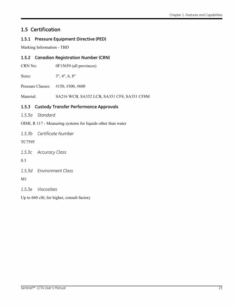
1.5 Certification
1.5.1 Pressure Equipment Directive (PED)
Marking Information - TBD
1.5.2 Canadian Registration Number (CRN)
CRN No: 0F15659 (all provinces)
Sizes: 3", 4", 6, 8"
Pressure Classes: #150, #300, #600
Material: SA216 WCB, SA352 LCB, SA351 CF8, SA351 CF8M
1.5.3 Custody Transfer Performance Approvals
1.5.3a Standard
OIML R 117 - Measuring systems for liquids other than water
1.5.3b Certificate Number
TC7595
1.5.3c Accuracy Class
0.3
1.5.3d Environment Class
M1
1.5.3e Viscosities
Up to 660 cSt; for higher, consult factory
Sentinel™ LCT4 User’s Manual 23
Chapter 1. Features and Capabilities
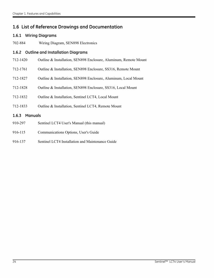
1.6 List of Reference Drawings and Documentation
1.6.1 Wiring Diagrams
702-884 Wiring Diagram, SEN898 Electronics
1.6.2 Outline and Installation Diagrams
712-1420 Outline & Installation, SEN898 Enclosure, Aluminum, Remote Mount
712-1761 Outline & Installation, SEN898 Enclosure, SS316, Remote Mount
712-1827 Outline & Installation, SEN898 Enclosure, Aluminum, Local Mount
712-1828 Outline & Installation, SEN898 Enclosure, SS316, Local Mount
712-1832 Outline & Installation, Sentinel LCT4, Local Mount
712-1833 Outline & Installation, Sentinel LCT4, Remote Mount
1.6.3 Manuals
910-297 Sentinel LCT4 User's Manual (this manual)
916-115 Communications Options, User's Guide
916-137 Sentinel LCT4 Installation and Maintenance Guide
24 Sentinel™ LCT4 User’s Manual
Chapter 1. Features and Capabilities
1.7 Disclaimer
The warranties set forth herein are exclusive and are in lieu of all other warranties whether statutory, express or implied (including warranties of merchantability and fitness for a particular purpose, and
warranties arising from course of dealing or usage or trade).
1.8 Warnings and Cautions
WARNING! The Sentinel Flow Measurement System can measure the flow rate of many fluids, some of which are potentially hazardous. The importance of proper safety practices cannot be overemphasized.
Be sure to follow all applicable local safety codes and regulations for installing electrical equipment and working with hazardous gases or flow conditions. Consult company safety personnel or local safety authorities to verify the safety of any procedure or practice.
!ATTENTION EUROPEAN CUSTOMERS!To meet CE Mark requirements, all cables must be installed as described in Appendix B,
CE Mark Compliance.
WARNING! Always disconnect the line power from the meter before removing either the front cover or the side cover. This is especially important in a hazardous environment.
WARNING! Improper connection of the line power leads or connecting a Sentinel to the incorrect line voltage may damage the unit. It may also result in hazardous voltages at the meter body and associated piping as well as within the electronics enclosure.
WARNING! Make sure the front and side covers, along with their O-ring seals, are installed on the transmitters, and the set screws tightened before applying power in a hazardous environment.
WARNING! Never remove the flowmeter covers in a hazardous environment while the line power is on.
Sentinel™ LCT4 User’s Manual 25

Chapter 1. Features and Capabilities
26 Sentinel™ LCT4 User’s Manual
Chapter 2. Installation
Chapter 2. Installation
2.1 Installation Guidelines
This section provides general information with respect to the mechanical and electrical installation, and should be thoroughly reviewed before the system is installed. To ensure safe and reliable operation of the Sentinel LCT4, the system must be installed in accordance with the guidelines established by GE Sensing, as explained in this chapter.
WARNING! The Sentinel LCT4 Ultrasonic Liquid Flow Transmitter can measure the flow rate of many liquids, some of which are potentially hazardous. The importance of proper safety practices cannot be overemphasized.
Be sure to follow all applicable local, national and company safety codes and regulations for installing electrical equipment and working with hazardous liquids or flow conditions. Consult company safety personnel or local safety authorities to verify the safety of any procedure or practice.
!ATTENTION EUROPEAN CUSTOMERS!To meet CE Mark requirements, all cables must be installed as described in Appendix B,
CE Mark Compliance.
IMPORTANT: This operating instruction fulfills the requirements of the Pressure Equipment Directive 97/23/EC. Please read it carefully in order to guarantee safe operation of this pressure equipment. Follow all warnings and instructions marked on the product.
2.2 Bill of Materials
The following items should have been included in the shipment:
• Sentinel LCT4 flowmeter
• Magnetic Wand
• User’s Manual
• CD with PanaView SEN898 Software (optional)
Sentinel™ LCT4 User’s Manual 27
Chapter 2. Installation
2.3 Unpacking
The Sentinel LCT4 will typically be packaged in a wooden crate, the size of which will depend on the size of product ordered. There Sentinel LCT4 will be secured by several 2x4 blocks to prevent shifting during transit. Simply remove these 2x4 braces to unpack the system. For local mount systems the transmitter will be installed directly on top of the pressure vessel. For remote mount systems the transmitter and remote cable may ship in a separate parcel.
2.4 Inspection
Prior to installation, inspect all material to be used in the installation.
• Gaskets - check for cracks, tears and over compression
• Nuts & Bolts - check for damaged threads and for debris
• RF Flange Faces - check for damage to serrations that may cause gaskets to not properly seal.
• Flow Conditioners - check for blockages or damage to the conditioner
In general, check for anything that may prevent safe operation of the equipment.
WARNING! If pipes are shipped pre-assembled as a single section, care should be taken to inspect and check the bolts and gaskets.
28 Sentinel™ LCT4 User’s Manual
Chapter 2. Installation
2.5 Mechanical Installation
2.5.1 Location
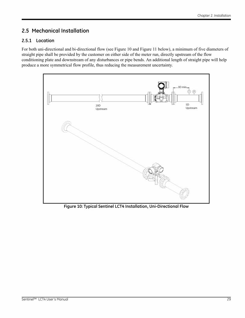
For both uni-directional and bi-directional flow (see Figure 10 and Figure 11 below), a minimum of five diameters of straight pipe shall be provided by the customer on either side of the meter run, directly upstream of the flow conditioning plate and downstream of any disturbances or pipe bends. An additional length of straight pipe will help produce a more symmetrical flow profile, thus reducing the measurement uncertainty.
Figure 10: Typical Sentinel LCT4 Installation, Uni-Directional Flow
20DUpstream
5DUpstream
3D min
Sentinel™ LCT4 User’s Manual 29

Chapter 2. Installation
2.5 Mechanical Installation (cont.)
Figure 11: Typical Sentinel LCT4 Installation, Bi-Directional Flow
Bi-Directional
20 D 20DT and P should be located elsewhere for bi-directional installations.
30 Sentinel™ LCT4 User’s Manual
Chapter 2. Installation
2.5.1 Installation Precautions
Any questions with respect to the installation should be addressed prior to beginning the installation. Failure to install the Sentinel LCT4 correctly can increase measurement uncertainty.
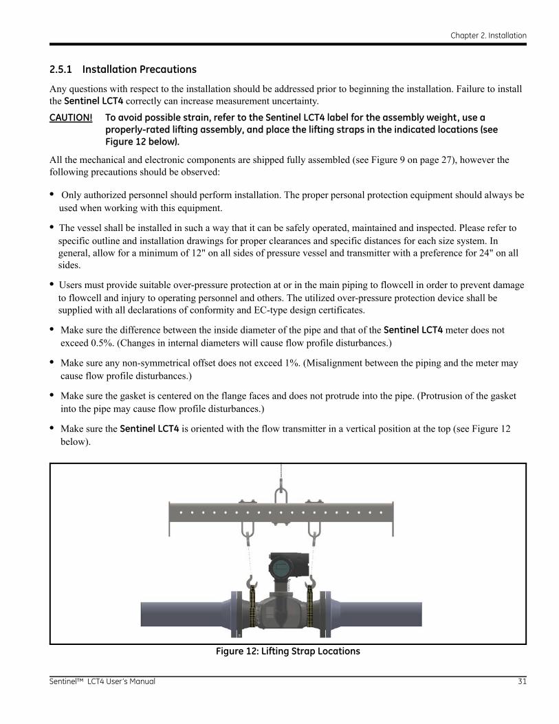
CAUTION! To avoid possible strain, refer to the Sentinel LCT4 label for the assembly weight, use a properly-rated lifting assembly, and place the lifting straps in the indicated locations (see Figure 12 below).
All the mechanical and electronic components are shipped fully assembled (see Figure 9 on page 27), however the following precautions should be observed:
• Only authorized personnel should perform installation. The proper personal protection equipment should always be used when working with this equipment.
• The vessel shall be installed in such a way that it can be safely operated, maintained and inspected. Please refer to specific outline and installation drawings for proper clearances and specific distances for each size system. In general, allow for a minimum of 12" on all sides of pressure vessel and transmitter with a preference for 24" on all sides.
• Users must provide suitable over-pressure protection at or in the main piping to flowcell in order to prevent damage to flowcell and injury to operating personnel and others. The utilized over-pressure protection device shall be supplied with all declarations of conformity and EC-type design certificates.
• Make sure the difference between the inside diameter of the pipe and that of the Sentinel LCT4 meter does not exceed 0.5%. (Changes in internal diameters will cause flow profile disturbances.)
• Make sure any non-symmetrical offset does not exceed 1%. (Misalignment between the piping and the meter may cause flow profile disturbances.)
• Make sure the gasket is centered on the flange faces and does not protrude into the pipe. (Protrusion of the gasket into the pipe may cause flow profile disturbances.)
• Make sure the Sentinel LCT4 is oriented with the flow transmitter in a vertical position at the top (see Figure 12 below).
Figure 12: Lifting Strap Locations
Sentinel™ LCT4 User’s Manual 31
Chapter 2. Installation
2.5.2 Lifting Instructions
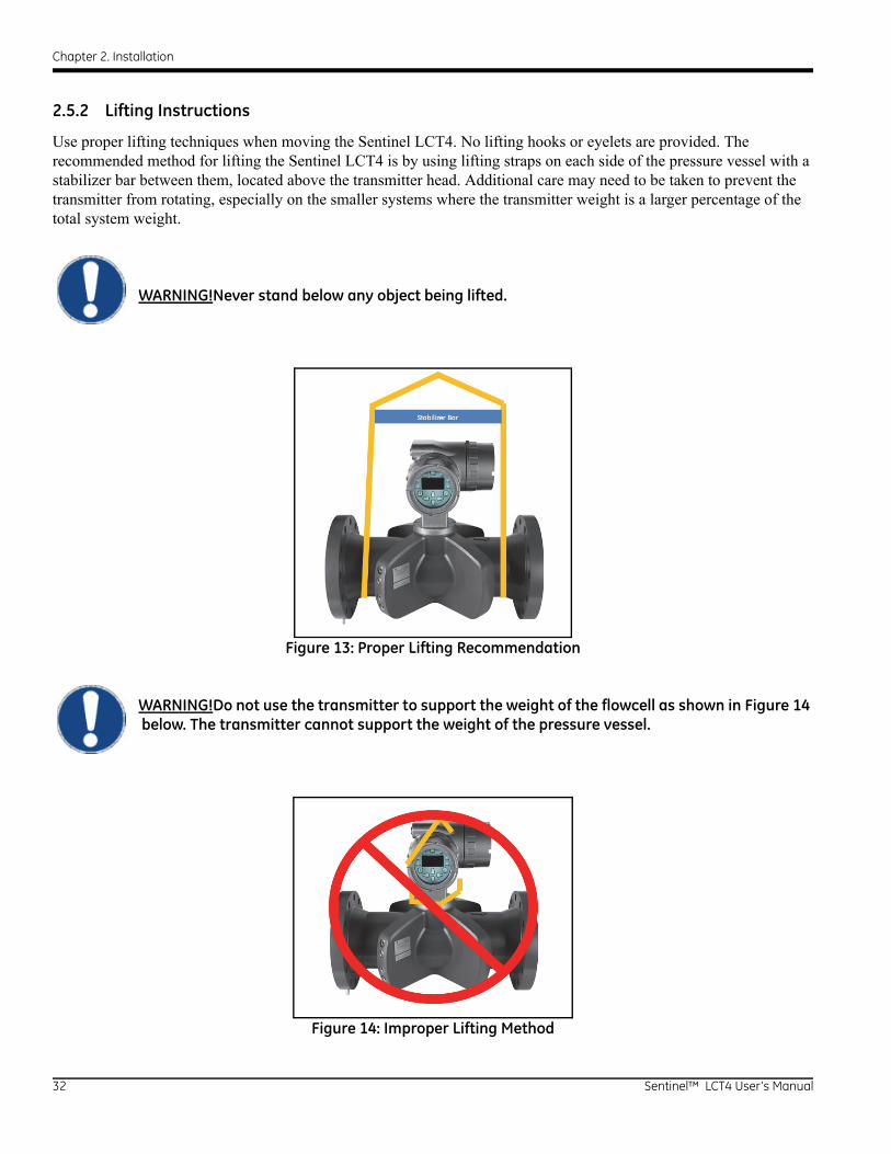
Use proper lifting techniques when moving the Sentinel LCT4. No lifting hooks or eyelets are provided. The recommended method for lifting the Sentinel LCT4 is by using lifting straps on each side of the pressure vessel with a stabilizer bar between them, located above the transmitter head. Additional care may need to be taken to prevent the transmitter from rotating, especially on the smaller systems where the transmitter weight is a larger percentage of the total system weight.
WARNING!Never stand below any object being lifted.
Figure 13: Proper Lifting Recommendation
WARNING!Do not use the transmitter to support the weight of the flowcell as shown in Figure 14 below. The transmitter cannot support the weight of the pressure vessel.
Figure 14: Improper Lifting Method
32 Sentinel™ LCT4 User’s Manual
Chapter 2. Installation
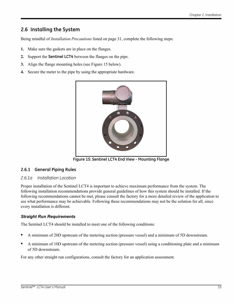
2.6 Installing the System
Being mindful of Installation Precautions listed on page 31, complete the following steps:
1. Make sure the gaskets are in place on the flanges.
2. Support the Sentinel LCT4 between the flanges on the pipe.
3. Align the flange mounting holes (see Figure 15 below).
4. Secure the meter to the pipe by using the appropriate hardware.
Figure 15: Sentinel LCT4 End View - Mounting Flange
2.6.1 General Piping Rules
2.6.1a Installation Location
Proper installation of the Sentinel LCT4 is important to achieve maximum performance from the system. The following installation recommendations provide general guidelines of how this system should be installed. If the following recommendations cannot be met, please consult the factory for a more detailed review of the application to see what performance may be achievable. Following these recommendations may not be the solution for all, since every installation is different.
Straight Run Requirements
The Sentinel LCT4 should be installed to meet one of the following conditions:
• A minimum of 20D upstream of the metering section (pressure vessel) and a minimum of 5D downstream.
• A minimum of 10D upstream of the metering section (pressure vessel) using a conditioning plate and a minimum of 5D downstream.
For any other straight run configurations, consult the factory for an application assessment.
Sentinel™ LCT4 User’s Manual 33
Chapter 2. Installation
Inner Diameter Matching
To maintain optimal product performance, the inner diameter of the upstream sections (20D or 10D with conditioning plate) should be within 0.5% of the metering section inner diameter at the flange. The downstream matching is not as critical but should be of the same schedule and matched as closely as possible.
In addition, gaskets should not protrude past the inner diameter to disrupt the flow profile.
Conditioning Plates & Tube Bundles
Conditioning plates are recommended over tube bundles for the Sentinel LCT4.
The conditioning plate should be installed to the manufacturer's recommendations but in general a minimum of 10D upstream of the metering section (pressure vessel) with a minimum of 5D of upstream of the conditioning plate is preferred. Conditioning plates should be installed the same way from calibration to the end user site. Visual indicators on the plates can assist users in orienting them properly.
WARNING! Conditioning plates do have directionality and need to be aligned properly with the direction of flow.
For use of any other type of conditioning plate, consult the factory for an application assessment.
Location of Temperature and Pressure Measurements
Temperature and pressure measurements should always made downstream of the Sentinel LCT4 and be located a minimum of 3 diameters downstream of the pressure vessel, with a preferred distance of 5 diameters downstream. For any other locations for temperature and pressure measurement consult the factory for an application assessment.
Calibration Recommendations
In general, the best practice is to calibrate as much of the measuring section as possible. This would include conditioning plates, upstream and downstream straight run and the Sentinel LCT4. While this is not always possible or cost effective this will provide the best transferability from calibration to field usage. This methodology is highly recommended for Custody Transfer Master Meter and Duty systems to maintain the lowest possible system uncertainty. Each application is different and requires a customized calibration plan. For calibration recommendations, consult the factory for an application assessment.
Fluid Comments
Gas - To avoid measurement errors suitable measures should be taken make sure the line is full and gas in the line is kept below 1%. While the system may still be able to measure with larger amounts, it has the potential to affect accuracy. When gas is present, keep flow rates as high as possible to help push the gas through the metering section.
Particulate - To avoid measurement errors suitable measures should be taken to minimize solid particulate in the line. Particulate should ideally be less than 1% for accurate measurement.
Water in Oil - Water and oil mixtures under 5% should be measurable and not affect accuracy as long as they are well mixed. Keep flow rates high enough to ensure a well-mixed solution. Higher percentages of water may be present but could affect accuracy of measurements.
Please consult the factory for any applications where conditions are outside the recommended ranges for a more comprehensive application review.
34 Sentinel™ LCT4 User’s Manual
Chapter 2. Installation
2.6.2 Guidelines for Installing Pipe Insulation
If pipe insulation is required:
1. Install all insulation materials and accessories in accordance with the manufacturer's instructions and the recognized industry practices. Adhere to the local code where applicable to ensure that the safe and proper installation will serve its intended purpose.
2. Install the insulation material in layers, with smooth and even surfaces. Allow adequate space (air pockets) around all extended transducer buffer rods, conduit fittings, junction boxes, and cables, for proper ventilation. Avoid using cut pieces or scrap insulation when abutting the sections being installed. Butt insulation joints firmly to ensure a complete, tight fit over and around all piping surfaces.
3. Maintain the integrity of any factory-applied vapor barrier jacketing on all pipe insulation, if applicable. Seal all joints and seams, protecting the insulation against puncture, tears or other damage.
Sentinel™ LCT4 User’s Manual 35

Chapter 2. Installation
2.7 Making Electrical Connections
This section contains instructions for making the necessary electrical connections to the flow transmitter (see Figure 16 below). The wiring between transmitter and transducers has been accomplished at the factory. No further work is required on this portion of the wiring.
IMPORTANT: When wires are connected to terminal blocks, use wire ties routed through the blocks, to secure them.
!ATTENTION EUROPEAN CUSTOMERS!To meet CE Mark requirements, all cables must be installed as described in Appendix B,
CE Mark Compliance.
IMPORTANT: The meter is grounded to the electronics. This configuration must be considered when applying cathodic protection to the pipe line. The power ground applied to the instrument should be at the cathodic protection voltage level.
Figure 16: Sentinel LCT4 Flow Measurement System Connections
Sentinel
TemperaturePressureRS232
orRS485
RS232/RS485 ModbusFlow
Computer
CorrectedVolumetric
Flow
PanaView™ SEN898Instrument Interface
Software
Meter Calibration, Data Collection,Configuration, and Security
2 Frequency2 Alarms1 Analog Output (4-20 mA) with HART3 Analog Inputs (4-20 mA) or2 Analog Inputs (4-20 mA) +
1 RTD Input
Sentinel LCT4
Power
36 Sentinel™ LCT4 User’s Manual

Chapter 2. Installation
2.7.1 Removing the Covers
WARNING! Always disconnect the line power from the meter before removing either the front display cover or the wiring access cover. This is especially important in a hazardous environment.
1. Disconnect any previously wired power line from the flow transmitter.
2. Loosen the set screw on the side cover using a 2.5 mm hex wrench.
3. Place a rod or long screwdriver across the cover in the slots provided, and rotate the cover counterclockwise until it comes free from the enclosure.
4. Note the text imprinted on the terminal board (see Figure 17 below) to assist in wiring the power and option card connections.
Proceed to the appropriate section of this chapter to make the desired wiring connections.
Figure 17: Terminal Board with Imprinted Text (Three 4-20mA Input Option shown)
L1 L2/N G
Sentinel™ LCT4 User’s Manual 37
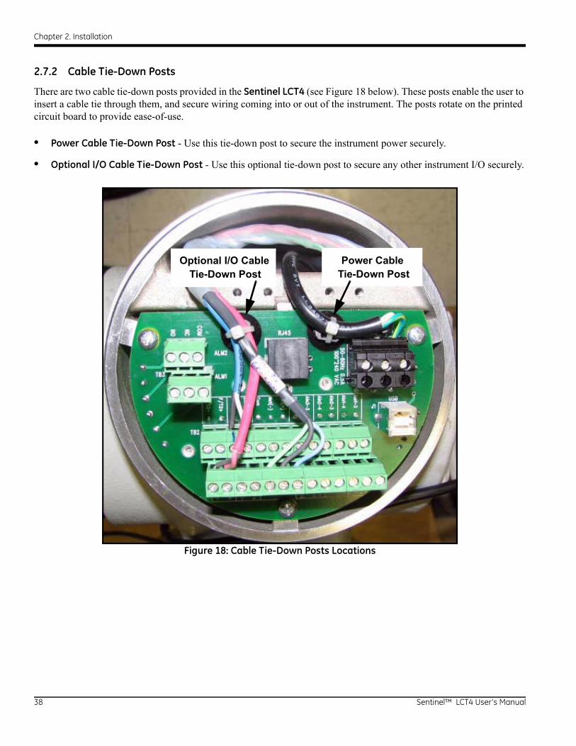
Chapter 2. Installation
2.7.2 Cable Tie-Down Posts
There are two cable tie-down posts provided in the Sentinel LCT4 (see Figure 18 below). These posts enable the user to insert a cable tie through them, and secure wiring coming into or out of the instrument. The posts rotate on the printed circuit board to provide ease-of-use.
• Power Cable Tie-Down Post - Use this tie-down post to secure the instrument power securely.
• Optional I/O Cable Tie-Down Post - Use this optional tie-down post to secure any other instrument I/O securely.
Figure 18: Cable Tie-Down Posts Locations
Power CableTie-Down Post
Optional I/O CableTie-Down Post
38 Sentinel™ LCT4 User’s Manual
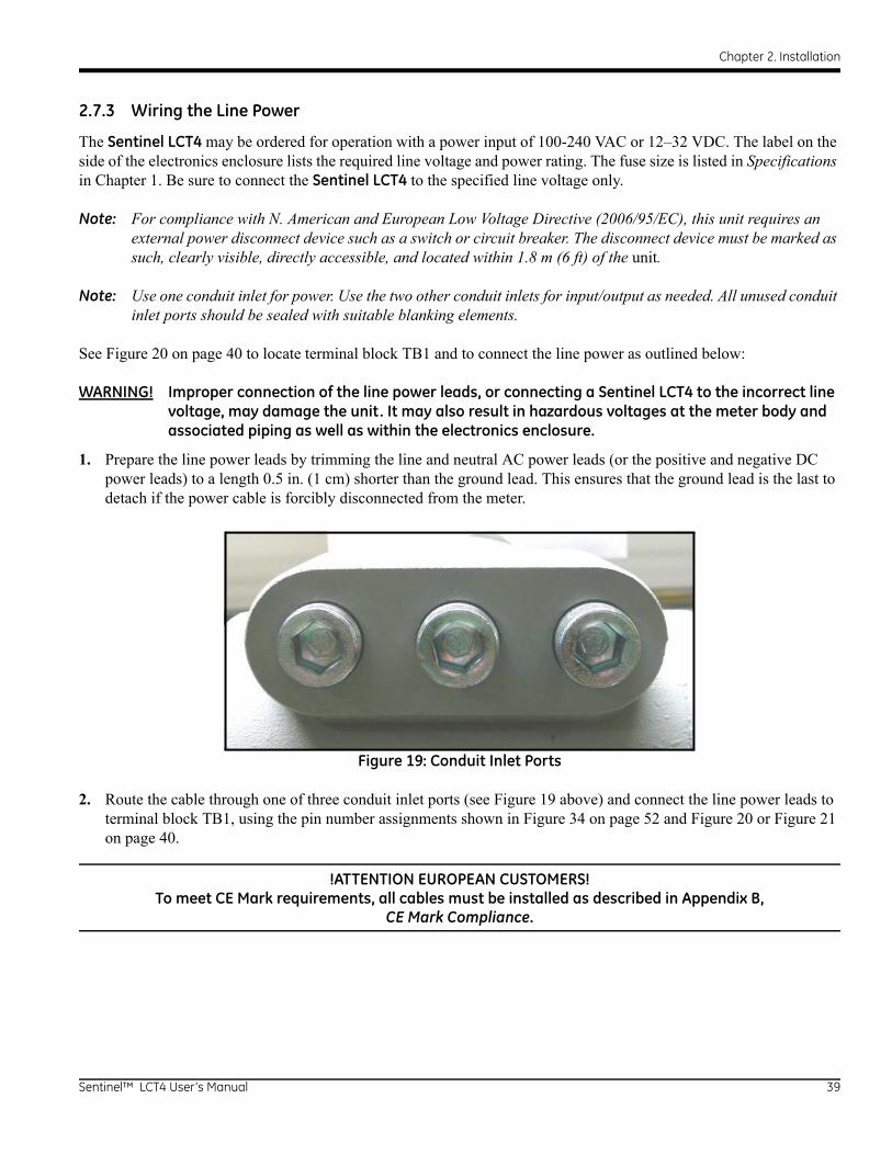
Chapter 2. Installation
2.7.3 Wiring the Line Power
The Sentinel LCT4 may be ordered for operation with a power input of 100-240 VAC or 12–32 VDC. The label on the side of the electronics enclosure lists the required line voltage and power rating. The fuse size is listed in Specifications in Chapter 1. Be sure to connect the Sentinel LCT4 to the specified line voltage only.
Note: For compliance with N. American and European Low Voltage Directive (2006/95/EC), this unit requires an external power disconnect device such as a switch or circuit breaker. The disconnect device must be marked as such, clearly visible, directly accessible, and located within 1.8 m (6 ft) of the unit.
Note: Use one conduit inlet for power. Use the two other conduit inlets for input/output as needed. All unused conduit inlet ports should be sealed with suitable blanking elements.
See Figure 20 on page 40 to locate terminal block TB1 and to connect the line power as outlined below:
WARNING! Improper connection of the line power leads, or connecting a Sentinel LCT4 to the incorrect line voltage, may damage the unit. It may also result in hazardous voltages at the meter body and associated piping as well as within the electronics enclosure.
1. Prepare the line power leads by trimming the line and neutral AC power leads (or the positive and negative DC power leads) to a length 0.5 in. (1 cm) shorter than the ground lead. This ensures that the ground lead is the last to detach if the power cable is forcibly disconnected from the meter.
Figure 19: Conduit Inlet Ports
2. Route the cable through one of three conduit inlet ports (see Figure 19 above) and connect the line power leads to terminal block TB1, using the pin number assignments shown in Figure 34 on page 52 and Figure 20 or Figure 21 on page 40.
!ATTENTION EUROPEAN CUSTOMERS!To meet CE Mark requirements, all cables must be installed as described in Appendix B,
CE Mark Compliance.
Sentinel™ LCT4 User’s Manual 39
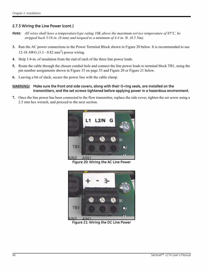
Chapter 2. Installation
2.7.3 Wiring the Line Power (cont.)
Note: All wires shall have a temperature/type rating 10K above the maximum service temperature of 85°C, be stripped back 5/16 in. (8 mm) and torqued to a minimum of 4.4 in. lb. (0.5 Nm).
3. Run the AC power connections to the Power Terminal Block shown in Figure 20 below. It is recommended to use
12-18 AWG (3.3 - 0.82 mm2) power wiring.
4. Strip 1/4-in. of insulation from the end of each of the three line power leads.
5. Route the cable through the chosen conduit hole and connect the line power leads to terminal block TB1, using the pin number assignments shown in Figure 35 on page 53 and Figure 20 or Figure 21 below.
6. Leaving a bit of slack, secure the power line with the cable clamp.
WARNING! Make sure the front and side covers, along with their O-ring seals, are installed on the transmitters, and the set screws tightened before applying power in a hazardous environment.
7. Once the line power has been connected to the flow transmitter, replace the side cover, tighten the set screw using a 2.5 mm hex wrench, and proceed to the next section.
Figure 20: Wiring the AC Line Power
Figure 21: Wiring the DC Line Power
L1 L2/N G
40 Sentinel™ LCT4 User’s Manual
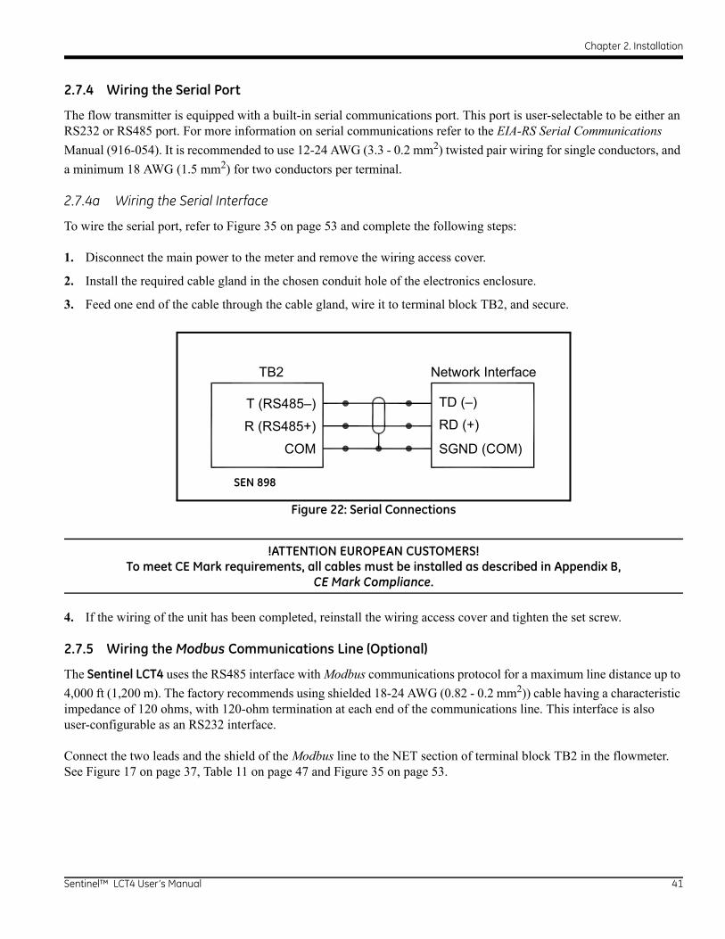
Chapter 2. Installation
2.7.4 Wiring the Serial Port
The flow transmitter is equipped with a built-in serial communications port. This port is user-selectable to be either an RS232 or RS485 port. For more information on serial communications refer to the EIA-RS Serial Communications
Manual (916-054). It is recommended to use 12-24 AWG (3.3 - 0.2 mm2) twisted pair wiring for single conductors, and
a minimum 18 AWG (1.5 mm2) for two conductors per terminal.
2.7.4a Wiring the Serial Interface
To wire the serial port, refer to Figure 35 on page 53 and complete the following steps:
1. Disconnect the main power to the meter and remove the wiring access cover.
2. Install the required cable gland in the chosen conduit hole of the electronics enclosure.
3. Feed one end of the cable through the cable gland, wire it to terminal block TB2, and secure.
Figure 22: Serial Connections
!ATTENTION EUROPEAN CUSTOMERS!To meet CE Mark requirements, all cables must be installed as described in Appendix B,
CE Mark Compliance.
4. If the wiring of the unit has been completed, reinstall the wiring access cover and tighten the set screw.
2.7.5 Wiring the Modbus Communications Line (Optional)
The Sentinel LCT4 uses the RS485 interface with Modbus communications protocol for a maximum line distance up to
4,000 ft (1,200 m). The factory recommends using shielded 18-24 AWG (0.82 - 0.2 mm2)) cable having a characteristic impedance of 120 ohms, with 120-ohm termination at each end of the communications line. This interface is also user-configurable as an RS232 interface.
Connect the two leads and the shield of the Modbus line to the NET section of terminal block TB2 in the flowmeter. See Figure 17 on page 37, Table 11 on page 47 and Figure 35 on page 53.
SGND (COM)
TD (–)
RD (+)
COM
R (RS485+)
T (RS485–)
TB2 Network Interface
SEN 898
Sentinel™ LCT4 User’s Manual 41

Chapter 2. Installation
2.7.6 Wiring the Alarm Relay
Note: The alarm relay can be wired as either Normally Open (NO) or Normally Closed (NC).
An alarm relay should be wired for fail-safe operation. In fail-safe mode, the alarm relay is constantly energized, except when it is triggered, or a power failure or other interruption occurs. See Figure 23 below for the operation of a normally open alarm relay in fail-safe mode.
Connect the alarm relay in accordance with the wiring instructions shown on the terminal board label (see Figure 17 on page 37 and Figure 33 on page 51). For a wiring diagram see Figure 35 on page 53.
Figure 23: Fail-Safe Operation
It is recommended to use 12-24 AWG (3.3 - 0.2 mm2) for single conductor wiring, and 16-24 AWG (1.5 - 0.2 mm2) for two conductors per terminal.
NC
C
NO
ALARMMONITORING
DEVICE
Fail-Safe(not triggered)
(triggered or power failure)Fail-Safe
DEVICEMONITORING
ALARM
NC
C
NO
42 Sentinel™ LCT4 User’s Manual
Chapter 2. Installation
2.7.7 Wiring the 4-20mA Analog Input (Optional)
1. Disconnect the main power to the flowmeter and remove the wiring access cover.
2. Install a cable gland in the chosen conduit hole of the electronics enclosure and feed a standard twisted-pair cable through this conduit hole.
3. Locate the 26-pin terminal block (TB2) in Figure 33 on page 51 and wire the I/O terminal as indicated on the label inside the wiring access cover (see Figure 17 on page 37 and Figure 33 on page 51). For a wiring diagram, see Figure 35 on page 53.
4. Secure the cable clamp.
!ATTENTION EUROPEAN CUSTOMERS!To meet CE Mark requirements, all cables must be installed as described in Appendix B,
CE Mark Compliance.
5. If wiring of the unit has been completed, reinstall the side cover on the enclosure and tighten the set screw.
The analog input option provides either three isolated 4-20mA analog inputs, or two isolated 4-20mA analog inputs and one RTD input (designated Ain1, Ain2, Ain3 and RTD1). Each of the 4-20 inputs includes a 24 VDC power supply for loop-powered transmitters. The inputs may be used to process temperature, density and pressure signals.
Note: To enter programming data during operation of the Sentinel LCT4, it will be necessary to know which input is assigned to which process parameter. This information should be entered in Appendix C, Data Records.
The analog inputs, which have an impedance of 118 ohms, should be connected with standard twisted-pair wiring. Power to the transmitters may be supplied either by the internal 24 VDC power supply on the analog input terminal or by an external power supply. Figure 24 on page 44 shows typical wiring diagrams, with and without an external power supply, for one of the analog inputs. Figure 25 on page 44 shows 4-wire RTD 100 input wiring. Wire the analog inputs as shown on the label in the enclosure side cover (see Figure 17 on page 37 and Figure 33 on page 51). Terminal locations are shown in Figure 26 on page 45 through Figure 29 on page 46.
It is recommended to use 12-24 AWG (3.3 - 0.2 mm2) for single conductor wiring, and 16-24 AWG (1.5 - 0.2 mm2) for two conductors per terminal.
Sentinel™ LCT4 User’s Manual 43
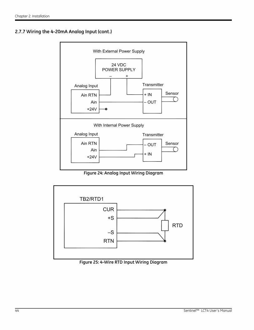
Chapter 2. Installation
2.7.7 Wiring the 4-20mA Analog Input (cont.)
Figure 24: Analog Input Wiring Diagram
Figure 25: 4-Wire RTD Input Wiring Diagram
+24V
Ain
Ain RTN
Ain
+24V
Ain RTN
+–
+ IN
– OUT
+ IN
– OUT
24 VDCPOWER SUPPLY
With External Power Supply
With Internal Power Supply
Analog Input Transmitter
TransmitterAnalog Input
Sensor
Sensor
–S
RTN
TB2/RTD1
CUR
+SRTD
44 Sentinel™ LCT4 User’s Manual
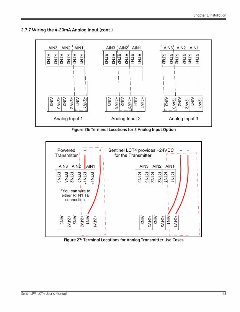
Chapter 2. Installation
2.7.7 Wiring the 4-20mA Analog Input (cont.)
Figure 26: Terminal Locations for 3 Analog Input Option
Figure 27: Terminal Locations for Analog Transmitter Use Cases
RTN
3
RTN
3R
TN2
RTN
2R
TN1
RTN
1
AIN
3
+24V3
AIN
2
+24V2
AIN
1
+24V1
AIN3 AIN2 AIN1
Analog Input 1
RTN
3
RTN
3R
TN2
RTN
2R
TN1
RTN
1
AIN
3
+24V3
AIN
2
+24V2
AIN
1
+24V1
AIN3 AIN2 AIN1
Analog Input 2
RTN
3
RTN
3R
TN2
RTN
2R
TN1
RTN
1
AIN
3
+24V3
AIN
2
+24V2
AIN
1
+24V1
AIN3 AIN2 AIN1
Analog Input 3
RTN
3
RTN
3R
TN2
RTN
2R
TN1*
RTN
1*
AIN
3
+24V3
AIN
2
+24V2
AIN
1
+24V1
AIN3 AIN2 AIN1
Powered
RTN
3
RTN
3R
TN2
RTN
2R
TN1
RTN
1
AIN
3
+24V3
AIN
2
+24V2
AIN
1
+24V1
AIN3 AIN2 AIN1
Sentinel LCT4 provides +24VDCTransmitter for the Transmitter
*You can wire toeither RTN1 TB
connection.
– + +–
Sentinel™ LCT4 User’s Manual 45
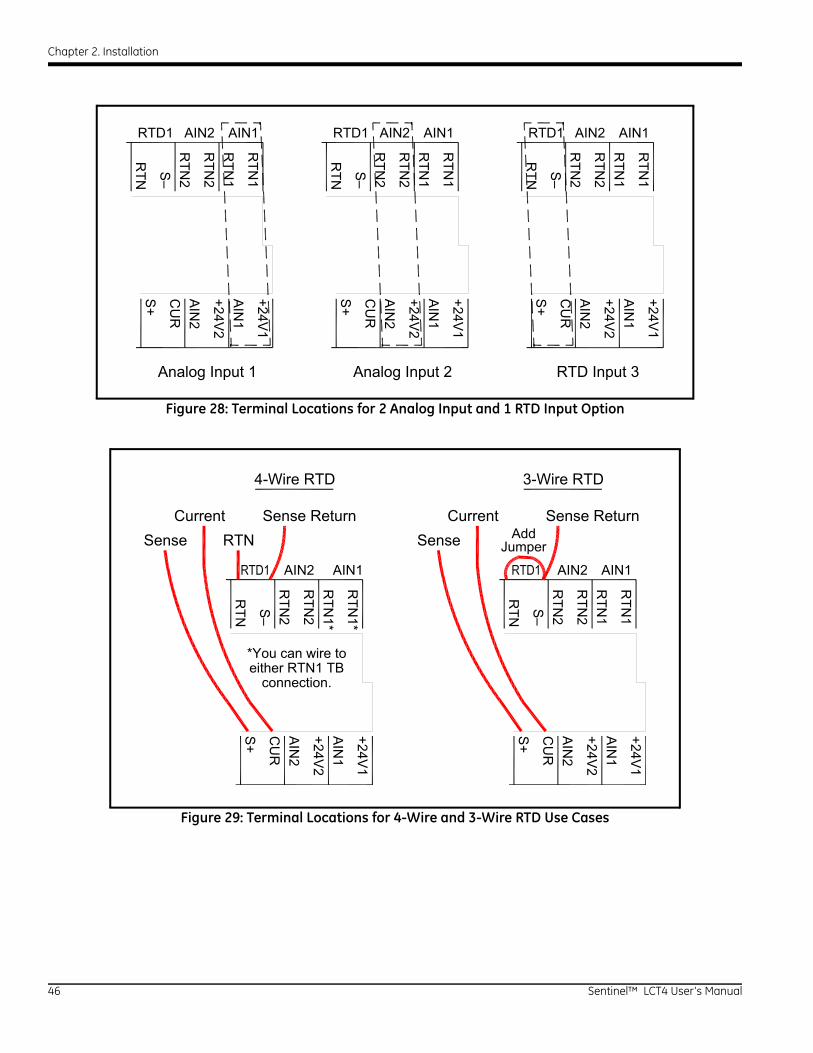
Chapter 2. Installation
Figure 28: Terminal Locations for 2 Analog Input and 1 RTD Input Option
Figure 29: Terminal Locations for 4-Wire and 3-Wire RTD Use Cases
RTN S
–R
TN2
RTN
2R
TN1
RTN
1
S+
CU
RA
IN2
+24V2
AIN
1
+24V1
RTD1 AIN2 AIN1
Analog Input 1
RTN
2
RTN
2R
TN1
RTN
1
AIN
2
+24V2
AIN
1
+24V1
AIN2 AIN1
Analog Input 2
RTN
2
RTN
2R
TN1
RTN
1
AIN
2
+24V2
AIN
1
+24V1
AIN2 AIN1
RTD Input 3
RTN S
–S
+
CU
R
RTN S
–S
+
CU
R
RTD1 RTD1
RTN S
–R
TN2
RTN
2R
TN1*
RTN
1*
S+
CU
RA
IN2
+24V2
AIN
1
+24V1
AIN2 AIN1
RTN
2
RTN
2R
TN1
RTN
1
AIN
2
+24V2
AIN
1
+24V1
AIN2 AIN1
4-Wire RTD
*You can wire toeither RTN1 TB
connection.
RTN
RTN S
–S
+
CU
R
CurrentSense
Sense Return CurrentSense
Sense Return
3-Wire RTD
AddJumper
46 Sentinel™ LCT4 User’s Manual

Chapter 2. Installation
2.7.8 Wiring the Frequency/Totalizer Output
Figure 30 below shows sample wiring diagrams of the frequency/totalizer output circuit for open drain and push-pull
configurations. It is recommended to use 12-24 AWG (3.3 - 0.2 mm2) for single conductor wiring, and 16-24 AWG
(1.5 - 0.2 mm2) for two conductors per terminal.
Figure 30: Totalizer and Frequency Output Wiring
Table 11: Wiring the TB2 I/O Terminal BlockI/O Pin # Function
F/T1+ Freq 1/Totalizer 1 OUT
F/T1– Freq 1/Totalizer 1 RTN
F/T2+ Freq 2/Totalizer 2 OUT
F/T2– Freq 2/Totalizer 2 RTN
NET R (+) MODBUS–RTU RS232 (R)/RS485 (+)
NET T (–) MODBUS–RTU RS232 (T)/RS485 (–)
NET COM MODBUS–RTU Common
OUT
RTN
IN
Common
Load
Volts -(Common)
Volts +(Int. Pwr. Sup.)
OUT
RTN
+5V
270
Frequency/Totalizer Output
Counter
CounterSentinel LCT4
Sentinel LCT4
Frequency/Totalizer Output(Open Drain)
(Push-Pull)
Sentinel™ LCT4 User’s Manual 47
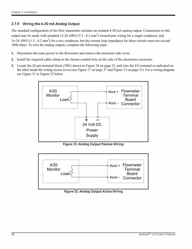
Chapter 2. Installation
2.7.9 Wiring the 4-20 mA Analog Output
The standard configuration of the flow transmitter includes an isolated 4-20 mA analog output. Connections to this
output may be made with standard 12-24 AWG (3.3 - 0.2 mm2) twisted-pair wiring for a single conductor, and
16-24 AWG (1.5 - 0.2 mm2) for a two conductor, but the current loop impedance for these circuits must not exceed 1000 ohms. To wire the analog outputs, complete the following steps:
1. Disconnect the main power to the flowmeter and remove the enclosure side cover.
2. Install the required cable clamp in the chosen conduit hole on the side of the electronics enclosure.
3. Locate the 26-pin terminal block (TB2) shown in Figure 34 on page 52, and wire the I/O terminal as indicated on the label inside the wiring access cover (see Figure 17 on page 37 and Figure 33 on page 51). For a wiring diagram see Figure 31 or Figure 32 below.
Figure 31: Analog Output Passive Wiring
Figure 32: Analog Output Active Wiring
Connector
TerminalFlowmeter
SupplyPower
24 Volt DC+ –
Board
Aout +
Aout –
Monitor4/20
Load
Connector
TerminalFlowmeter
Board
Aout +
Aout –
Monitor4/20
Load
48 Sentinel™ LCT4 User’s Manual
Chapter 2. Installation
2.7.9 Wiring the 4-20 mA Analog Output (cont.)
4. Secure the cable clamp.
!ATTENTION EUROPEAN CUSTOMERS!To meet CE Mark requirements, all cables must be installed as described in Appendix B,
CE Mark Compliance.
5. If wiring of the unit has been completed, reinstall the wiring access cover on the enclosure and tighten the set screw.
After the Sentinel LCT4 has been completely installed and wired, proceed to Chapter 3, Operation, to program the flowmeter.
WARNING! Make sure both covers, with their o-ring seals, are installed, and the set screws tightened, before applying power in a hazardous environment.
Sentinel™ LCT4 User’s Manual 49

Chapter 2. Installation
50 Sentinel™ LCT4 User’s Manual

Chapter 2. Installation
Se 51
Wiring Access Cover
Figu
re 3
3: S
EN89
8 El
ectr
onic
s En
clos
ure
- Fr
ont
Dis
play
and
Wir
ing
Acc
ess
Cov
er
ntinel™ LCT4 User’s Manual
Front Display
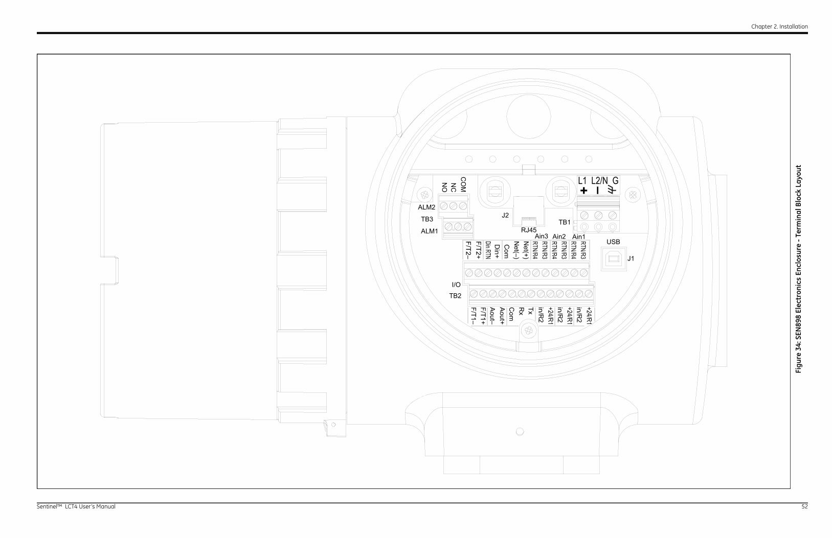
Chapter 2. Installation
Se 52
TB1
USB
J1
J2
RJ45Ain3 Ain2 Ain1
in/R2
in/R2
in/R2
TxRx
Com
Aout+
+ –
Figu
re 3
4: S
EN89
8 El
ectr
onic
s En
clos
ure
- Te
rmin
al B
lock
Lay
out
ntinel™ LCT4 User’s Manual
ALM1
ALM2
TB3
I/O
TB2
Aout–
F/T1+F/T1–
CO
MNC
NO

Chapter 2. Installation
Se 53
MODBUS / TCP CONNECTOR (NON-IS ONLY)
POWER CORD TERMINAL
AC OPTION:L1 LINE 1L2/N LINE 2/NEUTRALG GROUND
USB CONNECTOR (NON-IS ONLY)
(3) ANALOG INPUTS OPTION (AAA)ANALOG INPUT 1AIN1 ANALOG IN+24V1 24VDCRTN1 24VDC RETURNRTN1 ANALOG RETURN
ANALOG INPUT 2AIN2 ANALOG IN+24V2 24VDCRTN2 24VDC RETURNRTN2 ANALOG RETURN
ANALOG INPUT 3AIN3 ANALOG IN+24V3 24VDCRTN3 24VDC RETURNRTN3 ANALOG RETURN
(2) ANALOG INPUTS & RTD INPUT OPTION (AAR)ANALOG INPUT 1AIN1 ANALOG IN+24V1 24VDCRTN1 24VDC RETURNRTN1 ANALOG RETURN
ANALOG INPUT 2AIN2 ANALOG IN+24V2 24VDCRTN2 24VDC RETURNRTN2 ANALOG RETURN
RTD INPUT 1S+ SENSE +CUR CURRENT OUTS- SENSE -RTN CURRENT RETURN
DC OPTION:+ (+)- (-)
GROUND
(SERVICE USE ONLY)
NOTES:1. I/O CONNECTIONS WIRE GAUGE RANGE 12-24 AWG (3.3 - 0.2 mm ).2
2. AC AND DC CONNECTIONS WIRE GAUGE RANGE 12-18 AWG (3.5 - .82 mm ).2
3. MAXIMUM TERMINAL RATINGS [VOLTAGE, CURRENT].
SEE NOTES 1 & 3 SEE NOTES 1 & 3
(264VAC, 0.82A)SEE NOTES 2 & 3
(30VDC, 2A)SEE NOTES 2 & 3
Figu
re 3
5: S
EN89
8 El
ectr
onic
s -
Wir
ing
Dia
gram
(ref
. dw
g #
702-
884)
ntinel™ LCT4 User’s Manual
PANALINK RS232/485T/- TRANSMIT / DATA-R/+ RECEIVE / DATA+COM COMMON
ANALOG OUTPUTAOUT+ 4-20mA POS TERMINALAOUT- 4-20mA NEG TERMINALPOWERED OR UNPOWEREDSOFTWARE SELECTABLE
FREQUENCY/TOTALIZER OUTPUTF/T1+ OUTPUT1 SIGNALF/T1- OUTPUT1 RETURNF/T2+ OUTPUT2 SIGNALF/T2- OUTPUT2 RETURN
GROUNDING SCREWS FOR 2-WIRESHIELD CABLES (RECOMMENDED)8-32 SCREW
DIGITAL INPUTDin+ TOTALIZER GATE SIGNALDin RTN TOTALIZER GATE RETURN
ALARM CONNECTORSALM1:NO NORMALLY OPENEDNC NORMALLY CLOSEDCOM COMMON
ALM2:NO NORMALLY OPENEDNC NORMALLY CLOSEDCOM COMMON
MODBUS NETWORK RS232/485T/- MODBUS (TRANSMIT / DATA -)R/+ MODBUS (RECEIVE / DATA +)COM MODBUS COMMON
(3) 3/4" NPT CABLE GLANDS PORTS(CABLE ENTRY ON OPPOSITE SIDE OF ENCLOSURE)
(2) CABLE TIE DOWN POINTS
F/T2–
F/T2+
Din+
Com
T (–)R
(+)
RTN
3
RTN
3R
TN2
RTN
2
RTN
1
RTN
1
F/T1–F/T1+A
out–A
out+C
omR
(+)T (-)A
IN3
AIN
2
AIN
1
TB2I/O
ALM2TB3
ALM1
NO
NC
CO
M
J2
NET AIN3 AIN2 AIN1
TB1
USB
J1
+ –
(±15VDC, 200mA)SEE NOTES 1 & 3
(5VDC, 100mA)SEE NOTES 1 & 3
AC (120VAC, 5A)DC (28VDC, 5A)SEE NOTES 1 & 3
(100VDC, 1A)SEE NOTES 1 & 3)
SEE NOTES 1 & 3
CUSTOMERGROUND
SEE NOTES 1 & 3
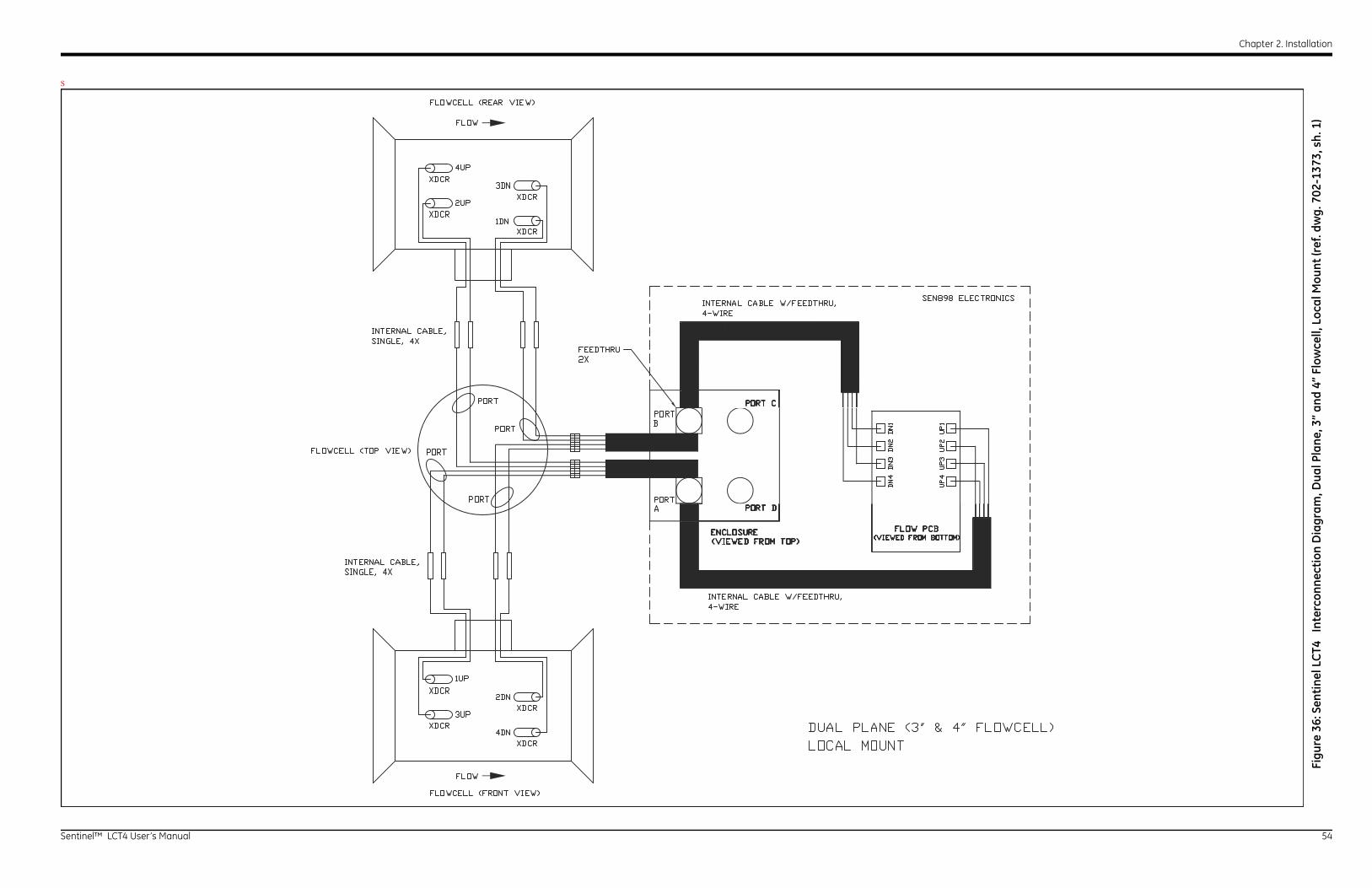
Chapter 2. Installation
Se 54
S
Figu
re 3
6: S
enti
nel L
CT4
In
terc
onne
ctio
n D
iagr
am, D
ual P
lane
, 3”
and
4” F
low
cell,
Loc
al M
ount
(ref
. dw
g. 7
02-1
373,
sh.
1)
ntinel™ LCT4 User’s Manual
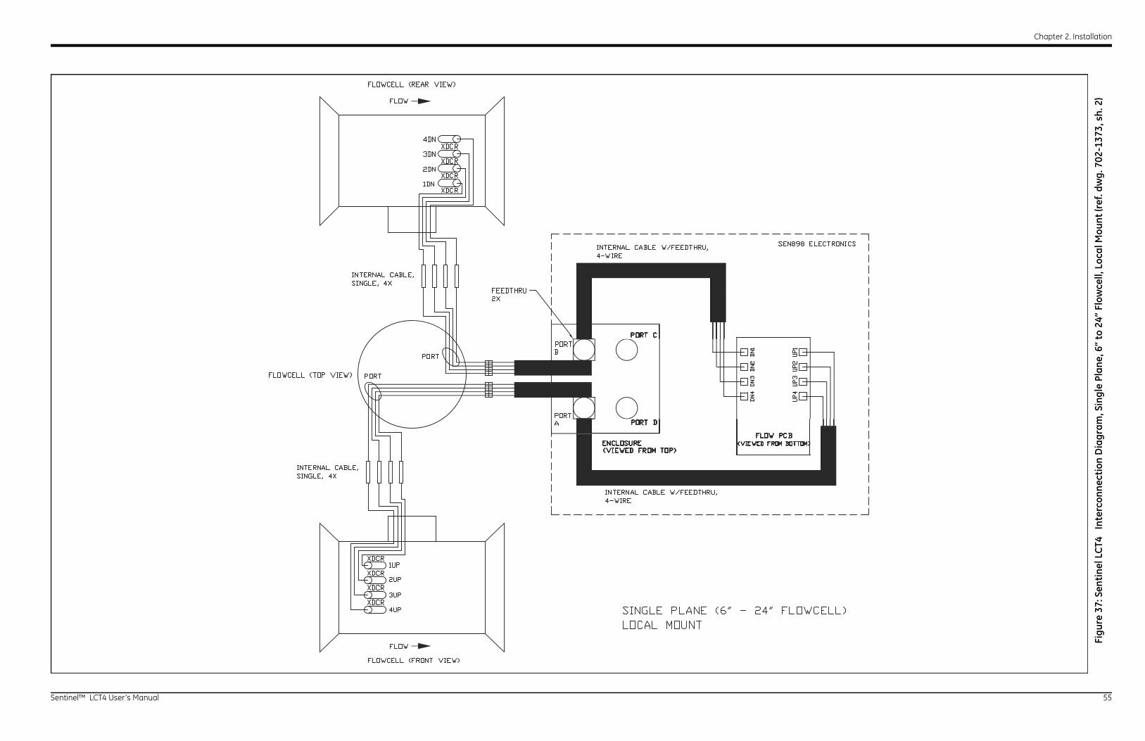
Chapter 2. Installation
Se 55
Figu
re 3
7: S
enti
nel L
CT4
In
terc
onne
ctio
n D
iagr
am, S
ingl
e Pl
ane,
6”
to 2
4” F
low
cell,
Loc
al M
ount
(ref
. dw
g. 7
02-1
373,
sh.
2)
ntinel™ LCT4 User’s Manual
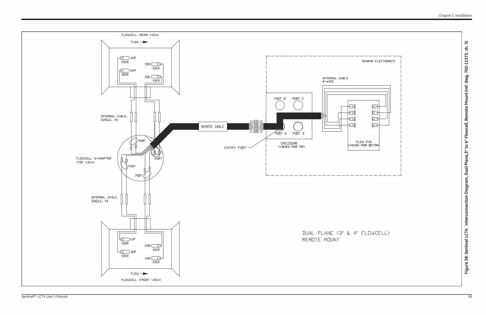
Chapter 2. Installation
Se 56
Figu
re 3
8: S
enti
nel L
CT4
In
terc
onne
ctio
n D
iagr
am, D
ual P
lane
,3”
to 4
” Fl
owce
ll, R
emot
e M
ount
(ref
. dw
g. 7
02-1
1373
, sh.
3)
ntinel™ LCT4 User’s Manual

Chapter 2. Installation
Se 57
Figu
re 3
9: S
enti
nel L
CT4
In
terc
onne
ctio
n D
iagr
am,S
ingl
e Pl
ane,
6”
to 2
4” F
low
cell,
Rem
ote
Mou
nt (r
ef. d
wg.
702
-137
3, s
h. 4
)
ntinel™ LCT4 User’s Manual

Chapter 2. Installation
Se 58
ntinel™ LCT4 User’s Manual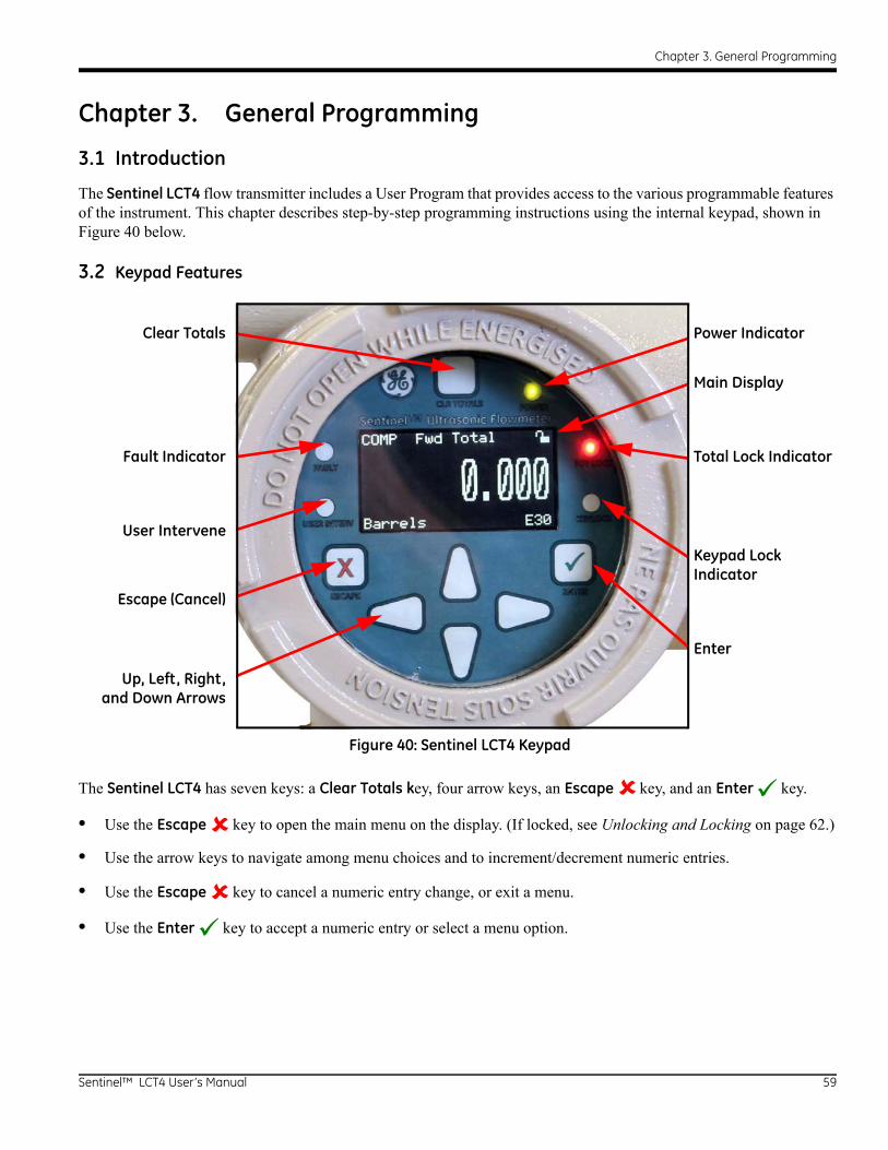
Chapter 3. General Programming
Chapter 3. General Programming
3.1 Introduction
The Sentinel LCT4 flow transmitter includes a User Program that provides access to the various programmable features of the instrument. This chapter describes step-by-step programming instructions using the internal keypad, shown in Figure 40 below.
3.2 Keypad Features
The Sentinel LCT4 has seven keys: a Clear Totals key, four arrow keys, an Escape key, and an Enter key.
• Use the Escape key to open the main menu on the display. (If locked, see Unlocking and Locking on page 62.)
• Use the arrow keys to navigate among menu choices and to increment/decrement numeric entries.
• Use the Escape key to cancel a numeric entry change, or exit a menu.
• Use the Enter key to accept a numeric entry or select a menu option.
Figure 40: Sentinel LCT4 Keypad
Clear Totals Power Indicator
Main Display
Fault Indicator Total Lock Indicator
User Intervene
Keypad Lock Indicator
Escape (Cancel)
Enter
Up, Left, Right,and Down Arrows
Sentinel™ LCT4 User’s Manual 59

Chapter 3. General Programming
3.2.1 Indicator Lights
If the Fault Indicator is lit, an instrument fault is detected. An error indication will be displayed in the lower right-hand corner of the Measurement View.
If the User Intervene Indicator is lit, an alarm has been triggered and will be kept latched until cleared by the user. See Wiring the Alarm Relay on page 42 and Inputs/Outputs on page 73 for more information.
The Keypad Lock Indicator will be lit if the Keypad Lock-Out Switch, internal to the instrument, has been engaged.
Note: If the Keypad Lock Indicator is lit, the keypad will not be functional.
The Total Lock Indicator will be lit if the Totals Lock-Out Switch, internal to the instrument, has been engaged.
Note: If the Total Lock Indicator is lit, totals are not able to be reset by the Clear Totals Key or through programming.
The Power Indicator is normally lit when the instrument is powered.
3.2.2 The Magnetic Stylus
Each of the keys can be selected using a hand-held magnet called a Magnetic Stylus, which is included with the meter. By touching the clear window at a key location, that key will be selected and will flash a red light to verify the contact.
Figure 41: Magnetic Stylus
60 Sentinel™ LCT4 User’s Manual

Chapter 3. General Programming
3.3 Program Menu Options
3.3.1 Channel Program
The Channel Program allows entry of configuration data for each physical channel, as well as settings adjustment. For the Channel Program setup, refer to the appropriate section for a discussion of the following PROG menu options, beginning on page 65.
3.3.2 Composite Program
The Composite Program allows entry of configuration data for the composite channel, as well as adjustment of settings, setup input and configuring API corrections. For the composite program setup, refer to the appropriate section for a discussion of the following Composite menu options, beginning on page 69.
3.3.3 Advanced Program
Note: The Advanced Program is accessible only to persons with Field Service, Factory or Engineering status.
Sentinel™ LCT4 User’s Manual 61

Chapter 3. General Programming
3.4 Unlocking and Locking
To prevent unauthorized tampering with either the display or the user program, the Sentinel LCT4 has multiple security codes. Once the security level has been set, one of these codes is required to change just the display (Display Lock), or the display and the user program (Full Lock).
3.4.1 Unlocking the Sentinel LCT4
To unlock the display and/or the user program:
1. Press [ESC], [ENT], [ESC]. A Security Check window, similar to Figure 42 below, appears.
Figure 42: Security Check Window
2. Using the arrow keys, change the code number to the value desired for your security level. The security passcodes can be configured under USER EDIT PASSCODES when the user is logged in as User Admin.
3. Press [ENT]. The display screen reappears, with the lock removed, partially unlocked, or lettered to represent the level. Security will remain at this level until you change the level in the user program, as described on the next page, or if it times out and returns to full lock.
Table 12: Default PasscodesLEVEL SECURITY LEVEL PASSCODE
0 Full Lock 0000 (Fixed)
1 Display Locked 2719 (Fixed)
2 User 1 0001*
3 User 2 0002*
4 User 3 0003*
5 User 4 0004*
6 User Admin 0005*
7 Field Service ----
8 Factory ----
9 Engineering/Unlock ----
*User Administrator Configurable
62 Sentinel™ LCT4 User’s Manual

Chapter 3. General Programming
3.4.2 Locking the Sentinel LCT4
The security level can be accessed in two ways.
From the display screen:
1. Press the [] or [] key, until the lock in the upper right corner is highlighted.
2. Press [ENT], and proceed to step 4 below.
From the User Program:
1. Press [ESC]. The Sentinel LCT4 enters the User Program.
2. Press the [] key until USER is bracketed.
3. Press the [] key until Set Security is highlighted. Press [ENT].
4. The screen shows the available options (depending on the current security level):
• Full Lock – This will be the default level during meter power-up. Any User who wishes to access the menu will have to press the keys in the following combination (Escape-Enter-Escape) to unlock the meter with a “Valid Passcode”. The entered “Passcode” is validated and the user is allowed to access the menu based on privileges. The meter will go back to Full-Lock mode if no keypad activity is noted for a “Determined Time”. (Default is 2 min.)
• Display Locked – This level can be achieved by entering a “Valid Passcode” assigned for this role. In this Mode/Level, the User has privilege only to view data. The User will be allowed to select the display parameters. Any other changeable parameter is denied access.
• User-1 / User-2 is basic user access.
• User-3 / User-4 is Power User access with additional privileges.
The User has to enter a “Valid Passcode” to have access to the menu attached to these roles. Users with these roles will have rights of Display Locked mode and some predetermined “write privilege” with which they may modify parameters (attached to these roles).
• User Admin – This User will have “Administrator privilege” in addition to privileges of Lower level. This user is given the rights to change the “Passcode” for all user-levels. (This does not include Full Lock and Display Locked). The Administrator has the privilege to modify the timeout value, which is used to determine the time taken to switch back to Full Lock mode (if no keypad activity is noted). The “Administrator privilege” does not include access to Service or Factory Menu. The Administrator has no rights or control on Service/Factory/Engineering Levels or their “Passcodes”.
• Field Service – This User has access to the “Service Menu” in addition to “Administrator privilege”. It is not accessible by User Admin.
• Factory – This User has access to “Factory privilege” in addition to “Service privileges”. It is not accessible by User Admin.
• Engineering – This User is the only user with Full access to the meter. It is not accessible by User Admin.
Sentinel™ LCT4 User’s Manual 63
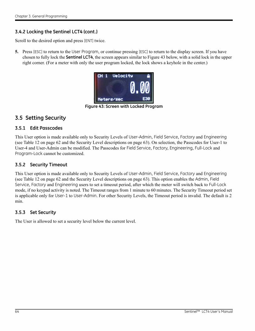
Chapter 3. General Programming
3.4.2 Locking the Sentinel LCT4 (cont.)
Scroll to the desired option and press [ENT] twice.
5. Press [ESC] to return to the User Program, or continue pressing [ESC] to return to the display screen. If you have chosen to fully lock the Sentinel LCT4, the screen appears similar to Figure 43 below, with a solid lock in the upper right corner. (For a meter with only the user program locked, the lock shows a keyhole in the center.)
Figure 43: Screen with Locked Program
3.5 Setting Security
3.5.1 Edit Passcodes
This User option is made available only to Security Levels of User-Admin, Field Service, Factory and Engineering (see Table 12 on page 62 and the Security Level descriptions on page 63). On selection, the Passcodes for User-1 to User-4 and User-Admin can be modified. The Passcodes for Field Service, Factory, Engineering, Full-Lock and Program-Lock cannot be customized.
3.5.2 Security Timeout
This User option is made available only to Security Levels of User-Admin, Field Service, Factory and Engineering (see Table 12 on page 62 and the Security Level descriptions on page 63). This option enables the Admin, Field Service, Factory and Engineering users to set a timeout period, after which the meter will switch back to Full-Lock mode, if no keypad activity is noted. The Timeout ranges from 1 minute to 60 minutes. The Security Timeout period set is applicable only for User-1 to User-Admin. For other Security Levels, the Timeout period is invalid. The default is 2 min.
3.5.3 Set Security
The User is allowed to set a security level below the current level.
64 Sentinel™ LCT4 User’s Manual
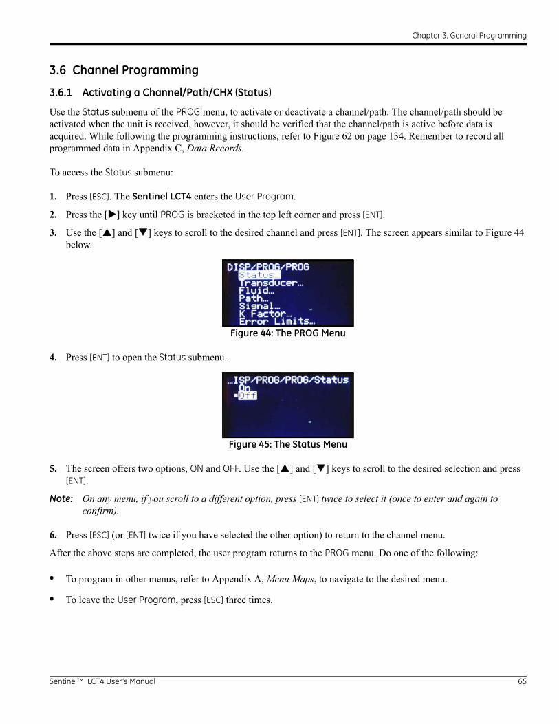
Chapter 3. General Programming
3.6 Channel Programming
3.6.1 Activating a Channel/Path/CHX (Status)
Use the Status submenu of the PROG menu, to activate or deactivate a channel/path. The channel/path should be activated when the unit is received, however, it should be verified that the channel/path is active before data is acquired. While following the programming instructions, refer to Figure 62 on page 134. Remember to record all programmed data in Appendix C, Data Records.
To access the Status submenu:
1. Press [ESC]. The Sentinel LCT4 enters the User Program.
2. Press the [] key until PROG is bracketed in the top left corner and press [ENT].
3. Use the [] and [] keys to scroll to the desired channel and press [ENT]. The screen appears similar to Figure 44 below.
Figure 44: The PROG Menu
4. Press [ENT] to open the Status submenu.
Figure 45: The Status Menu
5. The screen offers two options, ON and OFF. Use the [] and [] keys to scroll to the desired selection and press [ENT].
Note: On any menu, if you scroll to a different option, press [ENT] twice to select it (once to enter and again to confirm).
6. Press [ESC] (or [ENT] twice if you have selected the other option) to return to the channel menu.
After the above steps are completed, the user program returns to the PROG menu. Do one of the following:
• To program in other menus, refer to Appendix A, Menu Maps, to navigate to the desired menu.
• To leave the User Program, press [ESC] three times.
Sentinel™ LCT4 User’s Manual 65

Chapter 3. General Programming
3.6.2 Entering Fluid Data (Not supported at this time)
The Fluid submenu enables selection of the Reynolds Correction factor. While following the programming instructions, see Figure 62 on page 134. Remember to record all programmed data in Appendix C, Data Records.
Note: From the PROG menu, proceed directly to Step 4. To select a different option, scroll to that option and press [ENT] twice to select it (once to enter and again to confirm the selection).
To access the Fluid submenu:
1. Press [ESC]. The Sentinel LCT4 enters the User Program.
2. Press the [] key until PROG is bracketed in the top left corner and press [ENT].
3. Use the [] and [] keys to scroll to the desired Channel and press [ENT].
4. Scroll to the Fluid submenu and press [ENT]. The word Reynolds appears.
3.6.2a Reynolds Correction Data
Reynolds Correction is a correction factor based on the Kinematic Viscosity and flow rate of the fluid. It is necessary, as the velocity of the fluid measured along a diametrical path must be related to the total area average velocity over the entire pipe cross-section. This factor should be ON in most applications, including all those that use clamp-on transducers. To access Reynolds Correction data:
1. From the Fluid window, select Reynolds and press [ENT]. The screen shows three options: Off, Single and Table.
2. Scroll to the desired option, and press [ENT]. The menu varies, depending on the selection in Step 1.
• If Off is chosen, no further choices are available.
• If Single is chosen, the Sentinel LCT4 will select and automatically display the Kinematic Viscosity. To change the value, press [ENT]. Use the arrow keys to change the value (available in document #914-004, Soundspeeds and Pipe Size Data), and press [ENT].
• If Table is selected, the screen displays four options: Units, Rows Used, Edit Table and Reset Table.
a. Select Units and press [ENT] and the screen displays two more options: Soundspeed and Diagnostic. Select Soundspeed and press [ENT] and the screen displays Meters/sec. Press [ESC] or [ENT] to return to the previous screen. Select Diagnostic and press [ENT] and the meter requests the type of signal to be used, Signal Up or Signal Dn. Scroll to the appropriate signal, and press [ENT].
b. From the Unit Menu, select Rows Used and press [ENT]. Use the arrow keys to enter the desired number (from 2 to 20) and press [ENT].
c. Select Edit Table and press [ENT], and the table opens with a series of rows. Scroll to the desired row, and press [ENT].
d. For each row, the screen displays the Reynolds Correction number (X) and the Kinematic Viscosity (KV). If you wish to change either value, scroll to the value and press [ENT]. Use the arrow keys to change the value (available in Soundspeeds and Pipe Size Data, document #914-004), and press [ENT].
e. Repeat steps c and d until all available data (from 2 to 20 rows) has been programmed.
f. Press [ESC] to return to the PROG menu, or continue pressing [ESC] until the display screen reappears.
g. To confirm changes to the table, from the Unit Menu, select Reset Table... and press Enter. To reset the table select Yes and press Enter. To not reset the table, select No and press Enter.
66 Sentinel™ LCT4 User’s Manual

Chapter 3. General Programming
3.6.3 Entering Signal Parameters
In the Signal submenu, set parameters that affect the transducer signal:
CAUTION! The SIGNAL default settings are suitable for most applications. Consult the factory before changing any of these settings.
Note: Under Channel Programming, the only signal parameter that can be changed is Zero Cutoff.
While following the programming instructions, refer to Figure 62 on page 134.
Note: From the PROG menu, proceed directly to Step 4. To select a different option, scroll to that option and press [ENT] twice to select it (once to enter and again to confirm the selection).
To enter the Signal submenu:
1. Press [ESC]. The Sentinel LCT4 enters the User Program.
2. Press the [] key until PROG is bracketed and press [ENT].
3. Use the [] and [] keys to scroll to the desired Channel and press [ENT].
4. Scroll to the Signal option and press [ENT].
5. The prompt requests the Zero Cutoff. Near “zero” flow, the Sentinel LCT4 may have fluctuating readings due to small offsets (caused by factors such as thermal drift in the fluid). The zero cutoff causes velocity measurements less than the cutoff to be reported as zero. To set the cutoff, press [ENT], and use the arrow keys to enter the new value. Press [ENT] to confirm the entry.
Entering parameters in the Signal option has been completed. Press [ESC] to return to the PROG menu, or continue pressing [ESC] until the display screen reappears.
Sentinel™ LCT4 User’s Manual 67

Chapter 3. General Programming
3.6.4 Entering Error Limits
The Error Limits option enables setting limits for an incoming signal. When the signal falls outside the programmed limits, an error indication appears on the display screen. To set error limits, follow the steps below.
Note: From the PROG menu, proceed directly to Step 4. To select a different option, scroll to that option and press [ENT] twice to select it (once to enter and again to confirm the selection).
1. Press [ESC]. The Sentinel LCT4 enters the User Program.
2. Press the [] key until PROG is bracketed in the upper left corner and press [ENT].
3. Use the [] and [] keys to scroll to the desired Channel and press [ENT].
4. Scroll to the Error Limits option and press [ENT].
5. The first prompt requests the Min Signal limit for the transducer signal received by the Sentinel LCT4. The E1:LOW SIGNAL error message appears if the signal strength falls below the limit programmed here. Press [ENT]. Use the arrow keys to change the value and press [ENT].
6. Repeat the steps above for the Max Signal limit.
7. The next prompt calls for the Min Velocity limit. Press [ENT]. Use the arrow keys to change the value and press [ENT].
8. Repeat the steps above to change the Max Velocity limit. (The E3:VELOCITY RANGE error message appears if the velocity falls outside the minimum and maximum limits.)
9. The meter now requests the Min Amplitude, the lower limit for the amplitude discriminator. The discriminator measures the size of the transducer signal sent from the Sentinel LCT4. If the signal falls outside these limits, the E5:AMPLITUDE error message appears. Press [ENT]. Use the arrow keys to change the value and press [ENT].
10. Repeat these steps for the Max Amplitude, the upper limit for the discriminator.
11. The next prompt calls for the acceptable Soundspeed limits, based on conditions in the particular system. The E2:SOUNDSPEED error message appears if the fluid soundspeed exceeds that entered in the Fluid submenu by more than this percentage. Press [ENT]. Use the arrow keys to change the percentage and press [ENT].
12. The next prompt requests the Acceleration limit for detecting cycle skipping. The E6:ACCELERATION error message appears if the velocity changes by more than this limit from one reading to the next. Press [ENT]. Use the arrow keys to change the value and press [ENT].
13. The final prompt requests the SNR signal for warning about poor signal-to-noise ratio. The E24:SNR error message appears if the SNR is below the programmed limit. Press [ENT]. Use the arrow keys to change the value and press [ENT].
You have finished entering data in the PROG menu. Do one of the following:
• To program in other menus, refer to Appendix A, Menu Maps, to navigate to the desired menu.
• To return to the display screen, press [ESC] until the display screen reappears.
• To configure the display, proceed to the next chapter.
68 Sentinel™ LCT4 User’s Manual

Chapter 3. General Programming
3.7 Composite Programming
Under the PROG menu, select Composite... and press [ENT].
3.7.1 Entering Fluid Type
1. Scroll to Fluid Type and press [ENT]. Two other options appear, Normal and Tracking. Tracking refers to Tracking Windows, which are used to detect the receive signal when you are unsure of the fluid soundspeed, or when the fluid soundspeed changes drastically under process conditions.
2. Scroll to the desired option and press [ENT].
3. Make a selection between Preprogrammed and Other fluids. Scroll to the desired option, and press [ENT].
• For Normal fluids, the expected fluid Temperature can be programmed. Scroll to the Temperature option and press [ENT]. Then use the arrow keys to enter the process temperature, and press [ENT].
• For fluids monitored with a Tracking Window, the meter enables the selection of Water (up to 100° or 260°C) or Oil. Scroll to the desired listing and press [ENT].
4. The menu now varies, depending on the selections in steps 6 and 7.
• If Preprogrammed Fluids has been selected, the Sentinel LCT4 supplies a list of preprogrammed fluids. As shown in Table 13 below, the list varies, depending on whether you have selected normal or tracking window fluid types. In either case, scroll to the desired fluid and press [ENT].
• If Other was selected, the Sentinel LCT4 requests the fluid soundspeed (for Normal fluids) or minimum and maximum soundspeed (for Tracking Window fluids). In either case, scroll to the Soundspeed option and press [ENT]. Use the arrow keys to enter the appropriate soundspeed, and press [ENT].
5. Press the [ESC] key to return to the Fluid Type window.
Table 13: Preprogrammed Fluid TypesTracking Windows Off Tracking Windows On
Water (0-260°C) Lube Oil (X200) Freon (R-12) Water (0-100°C)
Sea Water Methanol (20°C) Diesel Water (0-260°C)
Oil (22°C) Ethanol Gasoline Oil
Crude Oil LN2 (-199°C) LNG
Sentinel™ LCT4 User’s Manual 69
Chapter 3. General Programming
3.7.2 Entering Signal Parameters
In the Signal submenu, set parameters that affect the transducer signal:
CAUTION! The SIGNAL default settings are suitable for most applications. Consult the factory before changing either of these settings.
• Error Allowed
• Compensation Status (additional option)
While following the programming instructions, refer to Figure 62 on page 134.
Note: From the COMPOSITE menu, proceed directly to Step 4. To select a different option, scroll to that option and press [ENT] twice to select it (once to enter and again to confirm the selection).
To enter the Signal submenu:
1. Press [ESC]. The Sentinel LCT4 enters the User Program.
2. Press the [] key until PROG is bracketed and press [ENT].
3. Use the [] and [] keys to scroll to Composite and press [ENT].
4. Scroll to the Signal option and press [ENT].
5. Select Error Allowed, press [ENT], use the arrow keys to enter the new value, and press [ENT] to confirm the entry.
6. If Dimensional Compensation is an included option, at the next parameter, Compensation Status, the screen shows the two options, On or Off. Scroll to the desired option, and press [ENT].
Entering parameters in the Signal option has been completed. Press [ESC] to return to the PROG menu, or continue pressing [ESC] until the display screen reappears.
3.7.3 Setting Up Input Data Feeds
In the Inputs submenu, set the status for three types of inputs:
• Temperature
• Pressure
• Density
1. From the COMPOSITE menu, select Inputs, and press [ENT]. The next screen lists three types of inputs: Temperature, Pressure, and Density.
2. Select the input to be changed and press [ENT]. The input status is described by two options: Fixed or Active.
3. To experience a stationary input, select Fixed, and press [ENT]. Press [ENT] again to reveal the Fixed input value.
4. To set a different value, use the arrow keys to change the digits, and press [ENT].
5. To experience an active input, select Active, and press [ENT]. Press [ESC] to return to the previous menu.
70 Sentinel™ LCT4 User’s Manual
Chapter 3. General Programming
3.7.4 Setting Up API (Additional Option)
In the API Setup submenu, set the table types and conditions for several API options:
1. If the API option is included, from the COMPOSITE menu, select API Setup, and press [ENT]. The next screen displays API Table Type and API Conditions.
3.7.4a API Table Type
1. Select API Table Type and press [ENT]. The next screen displays four table types: Table A-Crude or JP, Table B-Gen Product, Table C-User Def TE, and Table D-Lubricants.
2. For Tables A, B and D, select a specific table, press [ENT], and the screen returns to the API Setup menu.
3. Select Table C, press [ENT], and the Thermal Exp Coeff screen appears. To change the coefficient, press [ENT]. On the next screen, use the arrow keys to change the digits, and press [ENT] to save the change, or [ESC] to reject the change. The screen returns to the previous display. Press [ESC] twice to return to the API Setup display.
3.7.4b API Conditions
1. Select API Conditions. Press [ENT]. The next screen displays two options: Base Condition and Flow Measure At...
2. Select Base Condition and press [ENT]. The next screen displays four options: 60°, 20°, 15° and User Defined... Select a given temperature or define a new one.
3. To establish a new base temperature, select User Defined, press [ENT], and the User Def Base Temp screen appears. Press [ENT], and the User Defined temperature is able to be changed.
4. Using the arrow keys, change the appropriate digits, and press [ENT]. Press [ESC] twice and return to the APIcond screen.
5. Select Flow Measure At... and press [ENT]. A screen appears listing two options: Observed and Alternate...
6. To measure at Observed, select Observed and press [ENT]. Two settings appear: Temp(alt) and Pres(alt).
7. To change either alternate condition, select the option, and press [ENT].
8. Using the arrow keys, change the appropriate digits, and press [ENT].
9. Change the other alternate condition if needed, and press [ESC] to return to the Flow Measurement At... screen.
10. To measure at Alternate, select Alternate and press [ENT]. Three settings appear: Temp(obs), Pres(obs), and Dens(obs).
11. To change an observed condition, select the option, and press [ENT].
12. Using the arrow keys, change the appropriate digits, and press [ENT].
13. Change the other observed conditions if needed, and press [ESC] four times to return to the PROG menu.
Sentinel™ LCT4 User’s Manual 71

Chapter 3. General Programming
3.8 Configuration
1. From the main menu, use the right arrow key to scroll to CONFIG. The screen displays five options: Units, Communication, Reset Totals, Totalizer Errors and Date/Time. Use the arrow keys to select an option to be configured.
2. To choose a measurement type, select Units, and press [ENT]. The screen displays Metric and English. Select one, press [ENT] and the screen returns to the CONFIG menu.
3. To choose a communication type, select Communication and press [ENT]. The screen displays three options: Panalink, Modbus (if option is included) and HART.
4. Select the desired communication software, press [ENT], and set up the components by making the appropriate selections from each list of options.
5. To reset the totals, from the CONFIG menu, select Reset Totals and press [ENT].
Note: If the totalizer lock is enabled, the previous totals will not be cleared.
a. Select a Channel, the Composite setup, or All, and press [ENT].
b. From the next menu, select whether to reset the forward total, the reverse total, or both, and press [ENT].
c. Press [ESC] to return to the CONFIG menu.
6. To set up error handling, from the CONFIG menu, select Totalizer Errors, and press [ENT].
a. Select a Channel or the Composite setup and press [ENT].
b. Answer the question, Totalize on Error?, by selecting Yes or No. Then press [ENT].
c. Repeat the process for other channels, if necessary, and press [ESC] to return to the CONFIG menu.
7. To reset the date and/or time, from the CONFIG menu, select Date/Time, and press [ENT].
a. Press [ENT] again to edit the text.
b. Use the arrow keys to select and change numbers in the date/time format.
c. Press [ENT] to accept the change.
72 Sentinel™ LCT4 User’s Manual

Chapter 3. General Programming
3.9 Inputs/Outputs
From the main menu, use the arrow keys to scroll to IO. The screen displays five options. Use the arrow keys to select an option to be configured.
• Analog Outputs
• Freq/Totals
• Alarms
• Slot 1
• Slot 2
While following the programming instructions, refer to Figure 65 on page 137 or Figure 66 on page 138.
Note: From the IO menu, proceed directly to Step 3. To select a different option, scroll to that option and press [ENT] twice to select it (once to enter and again to confirm the selection).
To enter the IO Menu:
1. Press [ESC]. The Sentinel LCT4 enters the User Program.
2. Press the [>] key until IO is bracketed and press [ENT].
3. Use the [^] and [V] keys to scroll to wanted IO option
3.9.1 Analog Output
1. Select Analog Output to bring you to the menu.
2. Select Status. Select Off to disable output or On to enable output.
3. Select the Channel of the data source you want to output.
4. Select the Publisher you want to output.
5. Select the Units for the Publisher output.
6. Enter a value for the Base (low end) of the chosen output range that corresponds to a 4mA output.
7. Enter a value for the Span (high end) of the chosen output range that corresponds to a 20mA output.
8. Choose the Error Level, the way the output will respond during an error condition:
9. Select Mode, either Passive or Active. Passive requires an external power supply, while Active is internally powered by the electronics.
Option Output Response
Hold Value Holds the last “good” reading.
Force Hi (20mA) Forces Output to 20mA.
Force Lo (4mA) Forces Output to 4mA.
Force HH Forces Output to 21mA
Force LL Forces Output to 3.8mA
Force Value Enables the user to enter a value between 4mA and 20mA, to be output during an error.
Sentinel™ LCT4 User’s Manual 73
Chapter 3. General Programming
3.9.2 Frequency/Totalizers
1. Select Freq/Totals to bring you to the menu.
2. Select Linked or Independent
Note: If you select Linked, both outputs will be setup the same, just 90° out of phase. If you select Independent, you will set up each output separately.
3. Select Freq/Total #1.
a. Status-Select On or Off
b. Mode-Select Frequency or Totalizer
c. Drive Ctl-Select Open Drain or Push-Pull
3.9.2a Frequency
1. Units - Choose the channel, parameter and units to output.
2. Fbase - Enter the lowest value of the Frequency range you want to output.
3. Fspan - Enter the highest value of the Frequency range you want to output.
4. Value(min) - Enter the value of the parameter you want to correspond to the min. value of the frequency range.
5. Value(max) - Enter the value of the parameter you want to correspond to the max. value of the frequency range.
6. Choose the Error Level, the way the output will respond during an error condition. Choose Force LO, Force HI, Hold Last, or Force Value. When the meter goes into Error, the chosen Error level will be output through the Frequency Output.:
3.9.2b Totalizer
1. Units - Choose the channel, parameter and units to output
2. Unit/Pulse - Choose how many units of the chosen parameter are accumulated until a pulse is sent out.
3. Pulse Width - Choose the length of each pulse output.
Note: Make sure the meter is not going to be outputting more than one pulse during this time, as this could lead to missed pulses.
4. Polarity - Choose the Negative or Positive edge of the pulse.
Option Output Response
Force Lo Forces Output to Fbase.
Force Hi Forces Output to Fspan.
Hold Last Holds the last “good” reading.
Force Value Enables the user to enter a value between the Frequency Range, to be output during an error.
74 Sentinel™ LCT4 User’s Manual
Chapter 3. General Programming
3.9.3 Alarms
1. Select Status, and choose either OFF, Normal, or Failsafe.
a. OFF - Disables alarm functionality.
b. Normal - Selection for conventional operation.
c. Failsafe - Selection for fail-safe operation.
2. If Normal or Failsafe has been chosen, select Type.
a. Level
Units - Defines the Unit of Measure for the alarm.
Trip Point - Defines the level where the alarm trips.
Dead Band - Defines the amount past the trip point where the alarm resets.
Trip Direction - Defines the direction of the alarm trip, above the set Trip Point or below the set Trip Point
Error Level -
Reset - Reset would force the alarm state to reset on error or fault condition. Reset would be such that NO would be NO, unless configured for failsafe.
Trip - Trip would force the alarm to Trip direction on error or fault condition.
Hold Last - Hold Last would hold the current state of the alarm on an error or fault condition.
b. Direction
The alarm can be tripped on forward or reverse flow. It uses volumetric in m3/s. The alarm will look for a positive or negative change in this flow reading.
c. Fault AlarmTrips the alarm on a particular fault, like E1 or E2. Can configure for individual faults, all faults or flow faults.
3. Choose Latch State
a. Latch - Enables the alarm to hold its state. This selection causes the User Intervene Indicator to be lit when an alarm occurs.
b. No Latch - The alarm is reset when the error condition clears.
c. Clear Latch - Changes the latched state. This will turn off the User Intervene Indicator if the meter is no longer in error.
Sentinel™ LCT4 User’s Manual 75
Chapter 3. General Programming
3.9.4 Analog Inputs (Additional Option)
If an option card is installed, Analog Inputs are available to the user.
1. Select the appropriate Slot for the Option Card.
2. Select the Ain item that you want to set up.
3. Enter a Value for the Label if you want it changed.
4. Select Mode and choose Off to turn off the input, or choose Temperature, Pressure or Density to set it up as one of those inputs.
a. Choose the Units for the input.
b. Enter the Base (low end) of the input.
c. Enter the Span (high end) of the input.
5. Select Cal to Trim the inputs.
If a Calibration is not going to be performed, load nominal calibration values by selecting Reset Trim. This will enable 4-20 to be read with undetermined accuracy. In order to meet accuracy, a proper Calibration must be performed.
• Make sure the inputs are wired correctly according to Figure 35 on page 53.
• Set the input to 4mA, for the Low end.
• Select Trim Base.
• Select Yes.
• Set the input to 20mA, for the High end.
• Select Trim Span.
• Select Yes.
• Calibration is complete.
76 Sentinel™ LCT4 User’s Manual
Chapter 3. General Programming
3.9.5 RTD (Additional Option)
If an option card is installed, an RTD Input may be available to the user, depending on the option card ordered.
1. Select the appropriate Slot for the Option Card.
2. Select the Temp(RTD) option
3. Enter in a Value for the Label if you want it changed
4. Select Mode and choose Off to turn off the input, or choose Temperature and select the input Temperature units.
5. Select CAL.
a. Make sure the RTD is connected to the terminal board correctly, according to Figure 35 on page 53.
b. GE Sensing's calibration process involves using a temperature bath and an iRTD (reference).
c. The iRTD is connected to iRTD Win Software to read the values.
d. The Meter is set up to display 1C:RTD.
e. Under IO/Slot 1/1C:Temp(RTD)/Mode choose temperature and enter in the right units.
f. A 2 to 5 point calibration is allowed with Sentinel LCT4.
Cal points must be entered with the lowest temperature starting at setpoint #1, and in increasing order to the highest setpoint.
Cal points must be performed over the full range to be measured. Temperatures that are out of the calibrated range (not on or between the highest and lowest setpoints) will not have calibration information applied to them and will not be corrected. “Falling off of the cal range,” or increasing the temperature beyond the last setpoint could cause data to be discontinuous.
Empty locations in the calibration table should be filled with the value '0'.
g. The Setpoint is the actual temperature that you are trying to read.
h. The Offset is the temperature the meter is reading from the probe minus the reference reading.
i. Run all points with the values set to 0, and then fill them in when all cal points are complete.
6. Select Reset Table if you want to return all Calibration Entries back to 0.
Sentinel™ LCT4 User’s Manual 77
Chapter 3. General Programming
3.10 Display
1. From the main menu, use the arrow keys to scroll to DISP. The screen displays four options: Views, Contrast, Backlight, and Mode. Use the arrow keys to select an option to be configured.
2. To set up display Views, select it, and press [ENT]. 1 View and 2 Views appear as options.
3. Move through the categories and set up each view as desired. Press [ESC] to return to the DISP menu.
4. To change the display Contrast, select it, and press [ENT]. Using the arrow keys, change the percentage digits as desired, and press [ENT]. The screen returns to the DISP menu.
5. To change the display Backlight, select it, and press [ENT]. Using the arrow keys, change the percentage digits as desired, and press [ENT]. The screen returns to the DISP menu.
6. To change the display Mode, select it, and press [ENT]. Select Normal or Reverse and press [ENT]. The screen returns to the DISP menu.
3.11 Calibration of Analog Output
1. Connect the Analog Output to an ammeter.
2. From the main menu, use the arrow keys to scroll to CAL. The screen displays one option: 4-20 Loop. Press [ENT] and four categories appear: Base Trim, Span Trim, Percent and Mode.
3. Select Mode, press [ENT], and select Test(Trim).
4. Set the percentage to 0% and press [ENT].
5. Select Base Trim, press [ENT], and using the arrow keys, enter what the ammeter is reading.
6. Set the percentage to 100% and press [ENT].
7. Select Span Trim, press [ENT], and using the arrow keys, enter what the ammeter is reading.
8. Go to Mode and select Normal.
9. Calibration of the 4-20mA Output Loop is complete.
3.12 User Security
• From the main menu, use the arrow keys to scroll to USER. The Edtcde screen displays three options: Edit Passcodes, Security, and Set Security.
3.12.1 Edit Passcodes
This User option is made available only to Security Levels of User-Admin, Field Service, Factory and Engineering (see Table 12 on page 62 and the Security Level descriptions on page 63). On selection, the Passcodes for User-1 to User-4 and User-Admin can be modified. The Passcodes for Field Service, Factory, Engineering, Full-Lock and Program-Lock cannot be customized.
• To enter or edit user passcodes, select Edit Passcodes, and press [ENT]. Select the USER/ADMIN number to be added or changed, and press [ENT]. Use the arrow keys to add or change the appropriate digits, and press [ENT].
78 Sentinel™ LCT4 User’s Manual

Chapter 3. General Programming
3.12.2 Security Timeout
This User option is made available only to Security Levels of User-Admin, Field Service, Factory and Engineering (see Table 12 on page 62 and the Security Level descriptions on page 63). This option enables the Admin, Field Service, Factory and Engineering users to set a timeout period, after which the meter will switch back to Full-Lock mode, if no keypad activity is noted. The Timeout ranges from 1 minute to 60 minutes. The Security Timeout period set is applicable only for User-1 to User-Admin. For other Security Levels, the Timeout period is invalid.
• To change the Security Timeout, select Security, and press [ENT]. Use the arrow keys to change the appropriate digits, and press [ENT].
3.12.3 Set Security
The User is allowed to set a security level below the current level.
• To set or change the security level, select Set Security, and press [ENT]. The screen lists ten options: Full Lock, Display Locked, User1 through 4, User Admin, Field Service, Factory, and Engineering. Select the appropriate level of security and press [ENT].
3.13 Factory Status
1. From the main menu, use the arrow keys to scroll to FACTORY. The screen displays five options: Versions, Default Meter, Upgrade, System Info, and Tag.
2. To set the version type, select Versions, and press [ENT]. The screen displays two options: Main and Option Cards.
3. Select Main, and press [ENT], and the screen displays Version Info. Press [ESC] and the screen returns to the Versions menu.
4. Select Option Cards, and press [ENT], and the screen displays Option Card Version Info. Press [ESC] and the screen returns to the Versions menu. Press [ESC] to return to the FACTORY menu.
IMPORTANT: Do not return the meter to default settings without speaking to someone at the factory first.
5. To return the meter to the default settings, from the FACTORY menu, select Default Meter and press [ENT]. Select Yes to confirm or No to cancel, and press [ENT]. The screen returns to the FACTORY menu.
IMPORTANT: Do not upgrade the meter’s code without speaking to someone at the factory first.
6. To upgrade the meter’s code, from the FACTORY menu, select Upgrade, and press [ENT]. Select Yes to confirm or No to cancel, and press [ENT]. The screen returns to the FACTORY menu.
7. To access system information, select System Info, and press [ENT]. The screen displays DATE/TIME and UpTime. Press [ESC] to return to the FACTORY menu.
8. To change the Tag, select the given name, and press [ENT]. Use the arrow keys to change the letters to the new name Tag. When complete, press [ENT], and the screen returns to the FACTORY menu.
Sentinel™ LCT4 User’s Manual 79

Chapter 3. General Programming
[no content intended for this page]
80 Sentinel™ LCT4 User’s Manual
Chapter 4. MODBUS Communications
Chapter 4. MODBUS Communications
4.1 Introduction
The Sentinel LCT4 supports digital communications using the MODBUS/RTU protocol, with 2-wire RS-485 or 3-wire RS-232C as the physical layer. Data rate can be specified from 4800 to 19,200 bits per second (bps), with selectable parity, and number of stop bits (Default = 9600, Even, 1 Stop Bit)
4.2 Setting Up MODBUS Communications
1. To set up MODBUS Communications, from the main screen, use the arrow keys to scroll to [CONFIG]. Select Communication and press ENTER, select Modbus and press ENTER.
2. Address: To change the MODBUS address, use the arrow keys to select Address and press [ENT]. Use the arrow keys to change the address number, and press [ENT] to save the change, or [ESC] to reject it. The screen returns to the CONFIG menu. The allowable address range is 1 to 255.
3. Interface: To set the interface to be used, from the CONFIG menu select Interface and press [ENT]. Two options appear: RS232 and RS485. Use the arrow keys to select the appropriate interface, and press [ENT]. The screen returns to the CONFIG menu.
4. WordOrder: To set the word order, from the CONFIG menu select WordOrder and press [ENT]. Two options appear: LowWordFirst and HighWord First. Use the arrow keys to select the appropriate order, and press [ENT]. The screen returns to the CONFIG menu.
5. Baud Rate: To set the baud rate, from the CONFIG menu select Baud Rate and press [ENT]. Three options appear: 4800, 9600 and 19200. Use the arrow keys to select the appropriate option, and press [ENT]. The screen returns to the CONFIG menu.
6. Parity: To set the parity, from the CONFIG menu select Parity and press [ENT]. Three options appear: None, Even and Odd. Use the arrow keys to select the appropriate option, and press [ENT]. The screen returns to the CONFIG menu.
Note: Considering several possible units are available for volumetric and totalizer output registers, a selection must be made to assign the conversion.
7. Volumetric: To set the volumetric measurement, from the CONFIG menu select Volumetric and press [ENT]. Twelve options appear. Use the arrow keys to select the appropriate measurement type, and press [ENT]. The screen returns to the CONFIG menu.
8. Total Units: To set the total units measurement, from the CONFIG menu select Total Units, and press [ENT]. Four
options appear: M3, Liters, Hectare-cm and Hectare-m. Use the arrow keys to select the appropriate measurement type, and press [ENT]. The screen returns to the CONFIG menu.
9. StdVolumetric: To set the standard volumetric measurement, from the CONFIG menu select StdVolumetric and press [ENT]. Twelve options appear. Use the arrow keys to select the appropriate measurement type, and press [ENT]. The screen returns to the CONFIG menu.
10. StdTotal Units: To set the standard total units measurement, from the CONFIG menu select StdTotal Units, and
press [ENT]. Four options appear: M3, Liters, Hectare-cm and Hectare-m. Use the arrow keys to select the appropriate measurement type, and press [ENT]. The screen returns to the CONFIG menu.
Modbus Communications are now set up and ready to use. Proceed to the following pages.
Sentinel™ LCT4 User’s Manual 81
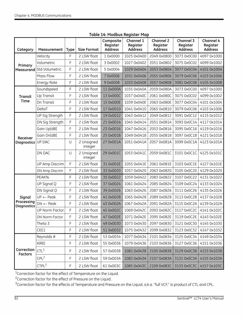
Chapter 4. MODBUS Communications
Table 14: Modbus Register Map
Category Measurement Type Size Format
Composite Register Address
Channel 1 Register Address
Channel 2 Register Address
Channel 3 Register Address
Channel 4 Register Address
Primary Measurand
Velocity F 2 LSW float 1 0x0000 1025 0x0400 2049 0x0800 3073 0x0C00 4097 0x1000
Volumetric F 2 LSW float 3 0x0002 1027 0x0402 2051 0x0802 3075 0x0C02 4099 0x1002
Std Volumetric F 2 LSW float 5 0x0004 1029 0x0404 2053 0x0804 3077 0x0C04 4101 0x1004
Mass Flow F 2 LSW float 7 0x0006 1031 0x0406 2055 0x0806 3079 0x0C06 4103 0x1006
Energy Rate F 2 LSW float 9 0x0008 1033 0x0408 2057 0x0808 3081 0x0C08 4105 0x1008
Transit Time
Soundspeed F 2 LSW float 11 0x000A 1035 0x040A 2059 0x080A 3073 0x0C00 4097 0x1000
Up Transit F 2 LSW float 13 0x000C 1037 0x040C 2061 0x080C 3075 0x0C02 4099 0x1002
Dn Transit F 2 LSW float 15 0x000E 1039 0x040E 2063 0x080E 3077 0x0C04 4101 0x1004
DeltaT F 2 LSW float 17 0x0010 1041 0x0410 2065 0x0810 3079 0x0C06 4103 0x1006
UP Sig Strength F 2 LSW float 19 0x0012 1043 0x0412 2049 0x0812 3091 0x0C12 4115 0x1012
DN Sig Strength F 2 LSW float 21 0x0014 1045 0x0414 2051 0x0814 3093 0x0C14 4117 0x1014
Gain Up[dB] F 2 LSW float 23 0x0016 1047 0x0416 2053 0x0816 3095 0x0C16 4119 0x1016
Receiver Diagnostics
Gain Dn[dB] F 2 LSW float 25 0x0018 1049 0x0418 2055 0x0818 3097 0x0C18 4121 0x1018
UP DAC U 2 Unsigned integer
27 0x001A 1051 0x041A 2057 0x081A 3099 0x0C1A 4123 0x101A
DN DAC U 2 Unsigned integer
29 0x001C 1053 0x041C 2059 0x081C 3101 0x0C1C 4125 0x101C
UP Amp Discrim F 2 LSW float 31 0x001E 1055 0x041E 2061 0x081E 3103 0x0C1E 4127 0x101E
DN Amp Discrim F 2 LSW float 33 0x0020 1057 0x0420 2063 0x0820 3105 0x0C20 4129 0x1020
PEAK% F 2 LSW float 35 0x0022 1059 0x0422 2083 0x0822 3107 0x0C22 4131 0x1022
UP Signal Q F 2 LSW float 37 0x0024 1061 0x0424 2085 0x0824 3109 0x0C24 4133 0x1024
DN Signal Q F 2 LSW float 39 0x0026 1063 0x0426 2087 0x0826 3111 0x0C26 4135 0x1026
Signal Processing Diagnostics
UP +– Peak F 2 LSW float 41 0x0028 1065 0x0428 2089 0x0828 3113 0x0C28 4137 0x1028
DN +– Peak F 2 LSW float 43 0x002A 1067 0x042A 2091 0x082A 3115 0x0C2A 4139 0x102A
UP Norm Factor F 2 LSW float 45 0x002C 1069 0x042C 2093 0x082C 3117 0x0C2C 4141 0x102C
DN Norm Factor F 2 LSW float 47 0x002E 1071 0x042E 2095 0x082E 3119 0x0C2E 4143 0x102E
Theta 3 F 2 LSW float 49 0x0030 1073 0x0430 2097 0x0830 3121 0x0C30 4145 0x1030
CEE1 F 2 LSW float 51 0x0032 1075 0x0432 2099 0x0832 3123 0x0C32 4147 0x1032
Reynolds # F 2 LSW float 53 0x0034 1077 0x0434 2101 0x0834 3125 0x0C34 4149 0x1034
Correction Factors
K(RE) F 2 LSW float 55 0x0036 1079 0x0436 2103 0x0836 3127 0x0C36 4151 0x1036
CTL1 F 2 LSW float 57 0x0038 1081 0x0438 2105 0x0838 3129 0x0C38 4153 0x1038
CPL2 F 2 LSW float 59 0x003A 1083 0x043A 2107 0x083A 3131 0x0C3A 4155 0x103A
CTPL3 F 2 LSW float 61 0x003C 1085 0x043C 2109 0x083C 3133 0x0C3C 4157 0x103C
1Correction factor for the effect of Temperature on the Liquid.2Correction factor for the effect of Pressure on the Liquid.3Correction factor for the effects of Temperature and Pressure on the Liquid, a.k.a. “full VCF,” is product of CTL and CPL.
82 Sentinel™ LCT4 User’s Manual
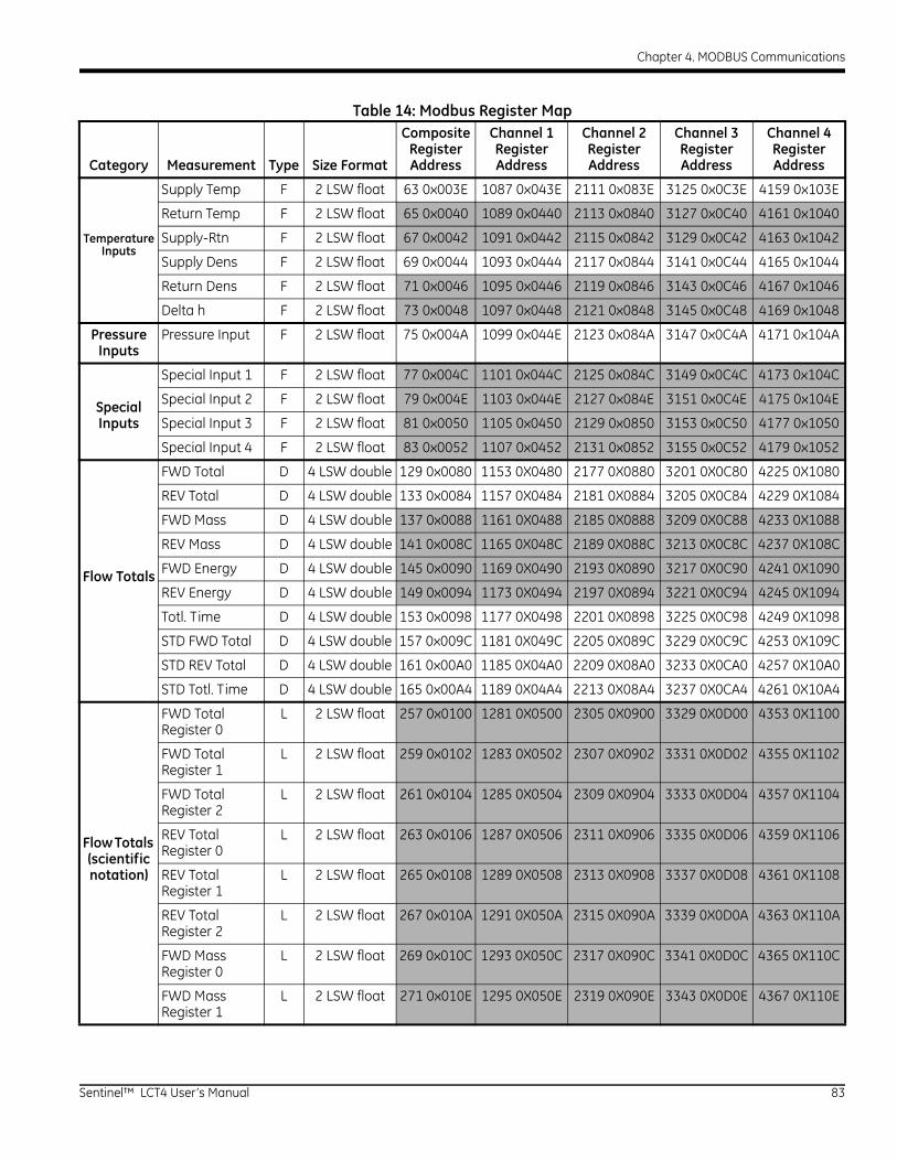
Chapter 4. MODBUS Communications
Supply Temp F 2 LSW float 63 0x003E 1087 0x043E 2111 0x083E 3125 0x0C3E 4159 0x103E
Return Temp F 2 LSW float 65 0x0040 1089 0x0440 2113 0x0840 3127 0x0C40 4161 0x1040
Temperature Inputs
Supply-Rtn F 2 LSW float 67 0x0042 1091 0x0442 2115 0x0842 3129 0x0C42 4163 0x1042
Supply Dens F 2 LSW float 69 0x0044 1093 0x0444 2117 0x0844 3141 0x0C44 4165 0x1044
Return Dens F 2 LSW float 71 0x0046 1095 0x0446 2119 0x0846 3143 0x0C46 4167 0x1046
Delta h F 2 LSW float 73 0x0048 1097 0x0448 2121 0x0848 3145 0x0C48 4169 0x1048
Pressure Inputs
Pressure Input F 2 LSW float 75 0x004A 1099 0x044E 2123 0x084A 3147 0x0C4A 4171 0x104A
Special Input 1 F 2 LSW float 77 0x004C 1101 0x044C 2125 0x084C 3149 0x0C4C 4173 0x104C
Special Inputs
Special Input 2 F 2 LSW float 79 0x004E 1103 0x044E 2127 0x084E 3151 0x0C4E 4175 0x104E
Special Input 3 F 2 LSW float 81 0x0050 1105 0x0450 2129 0x0850 3153 0x0C50 4177 0x1050
Special Input 4 F 2 LSW float 83 0x0052 1107 0x0452 2131 0x0852 3155 0x0C52 4179 0x1052
FWD Total D 4 LSW double 129 0x0080 1153 0X0480 2177 0X0880 3201 0X0C80 4225 0X1080
REV Total D 4 LSW double 133 0x0084 1157 0X0484 2181 0X0884 3205 0X0C84 4229 0X1084
FWD Mass D 4 LSW double 137 0x0088 1161 0X0488 2185 0X0888 3209 0X0C88 4233 0X1088
REV Mass D 4 LSW double 141 0x008C 1165 0X048C 2189 0X088C 3213 0X0C8C 4237 0X108C
Flow Totals FWD Energy D 4 LSW double 145 0x0090 1169 0X0490 2193 0X0890 3217 0X0C90 4241 0X1090
REV Energy D 4 LSW double 149 0x0094 1173 0X0494 2197 0X0894 3221 0X0C94 4245 0X1094
Totl. Time D 4 LSW double 153 0x0098 1177 0X0498 2201 0X0898 3225 0X0C98 4249 0X1098
STD FWD Total D 4 LSW double 157 0x009C 1181 0X049C 2205 0X089C 3229 0X0C9C 4253 0X109C
STD REV Total D 4 LSW double 161 0x00A0 1185 0X04A0 2209 0X08A0 3233 0X0CA0 4257 0X10A0
STD Totl. Time D 4 LSW double 165 0x00A4 1189 0X04A4 2213 0X08A4 3237 0X0CA4 4261 0X10A4
FWD Total Register 0
L 2 LSW float 257 0x0100 1281 0X0500 2305 0X0900 3329 0X0D00 4353 0X1100
FWD Total Register 1
L 2 LSW float 259 0x0102 1283 0X0502 2307 0X0902 3331 0X0D02 4355 0X1102
FWD Total Register 2
L 2 LSW float 261 0x0104 1285 0X0504 2309 0X0904 3333 0X0D04 4357 0X1104
Flow Totals (scientific notation)
REV Total Register 0
L 2 LSW float 263 0x0106 1287 0X0506 2311 0X0906 3335 0X0D06 4359 0X1106
REV Total Register 1
L 2 LSW float 265 0x0108 1289 0X0508 2313 0X0908 3337 0X0D08 4361 0X1108
REV Total Register 2
L 2 LSW float 267 0x010A 1291 0X050A 2315 0X090A 3339 0X0D0A 4363 0X110A
FWD Mass Register 0
L 2 LSW float 269 0x010C 1293 0X050C 2317 0X090C 3341 0X0D0C 4365 0X110C
FWD Mass Register 1
L 2 LSW float 271 0x010E 1295 0X050E 2319 0X090E 3343 0X0D0E 4367 0X110E
Table 14: Modbus Register Map
Category Measurement Type Size Format
Composite Register Address
Channel 1 Register Address
Channel 2 Register Address
Channel 3 Register Address
Channel 4 Register Address
Sentinel™ LCT4 User’s Manual 83
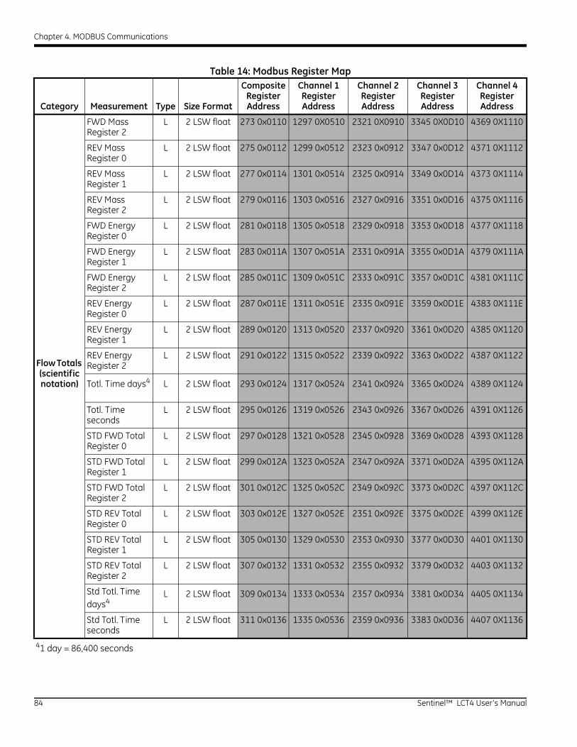
Chapter 4. MODBUS Communications
FWD Mass Register 2
L 2 LSW float 273 0x0110 1297 0X0510 2321 0X0910 3345 0X0D10 4369 0X1110
REV Mass Register 0
L 2 LSW float 275 0x0112 1299 0x0512 2323 0x0912 3347 0x0D12 4371 0X1112
REV Mass Register 1
L 2 LSW float 277 0x0114 1301 0x0514 2325 0x0914 3349 0x0D14 4373 0X1114
REV Mass Register 2
L 2 LSW float 279 0x0116 1303 0x0516 2327 0x0916 3351 0x0D16 4375 0X1116
FWD Energy Register 0
L 2 LSW float 281 0x0118 1305 0x0518 2329 0x0918 3353 0x0D18 4377 0X1118
FWD Energy Register 1
L 2 LSW float 283 0x011A 1307 0x051A 2331 0x091A 3355 0x0D1A 4379 0X111A
FWD Energy Register 2
L 2 LSW float 285 0x011C 1309 0x051C 2333 0x091C 3357 0x0D1C 4381 0X111C
REV Energy Register 0
L 2 LSW float 287 0x011E 1311 0x051E 2335 0x091E 3359 0x0D1E 4383 0X111E
REV Energy Register 1
L 2 LSW float 289 0x0120 1313 0x0520 2337 0x0920 3361 0x0D20 4385 0X1120
Flow Totals (scientific notation)
REV Energy Register 2
L 2 LSW float 291 0x0122 1315 0x0522 2339 0x0922 3363 0x0D22 4387 0X1122
Totl. Time days4 L 2 LSW float 293 0x0124 1317 0x0524 2341 0x0924 3365 0x0D24 4389 0X1124
Totl. Time seconds
L 2 LSW float 295 0x0126 1319 0x0526 2343 0x0926 3367 0x0D26 4391 0X1126
STD FWD Total Register 0
L 2 LSW float 297 0x0128 1321 0x0528 2345 0x0928 3369 0x0D28 4393 0X1128
STD FWD Total Register 1
L 2 LSW float 299 0x012A 1323 0x052A 2347 0x092A 3371 0x0D2A 4395 0X112A
STD FWD Total Register 2
L 2 LSW float 301 0x012C 1325 0x052C 2349 0x092C 3373 0x0D2C 4397 0X112C
STD REV Total Register 0
L 2 LSW float 303 0x012E 1327 0x052E 2351 0x092E 3375 0x0D2E 4399 0X112E
STD REV Total Register 1
L 2 LSW float 305 0x0130 1329 0x0530 2353 0x0930 3377 0x0D30 4401 0X1130
STD REV Total Register 2
L 2 LSW float 307 0x0132 1331 0x0532 2355 0x0932 3379 0x0D32 4403 0X1132
Std Totl. Time days4
L 2 LSW float 309 0x0134 1333 0x0534 2357 0x0934 3381 0x0D34 4405 0X1134
Std Totl. Time seconds
L 2 LSW float 311 0x0136 1335 0x0536 2359 0x0936 3383 0x0D36 4407 0X1136
41 day = 86,400 seconds
Table 14: Modbus Register Map
Category Measurement Type Size Format
Composite Register Address
Channel 1 Register Address
Channel 2 Register Address
Channel 3 Register Address
Channel 4 Register Address
84 Sentinel™ LCT4 User’s Manual
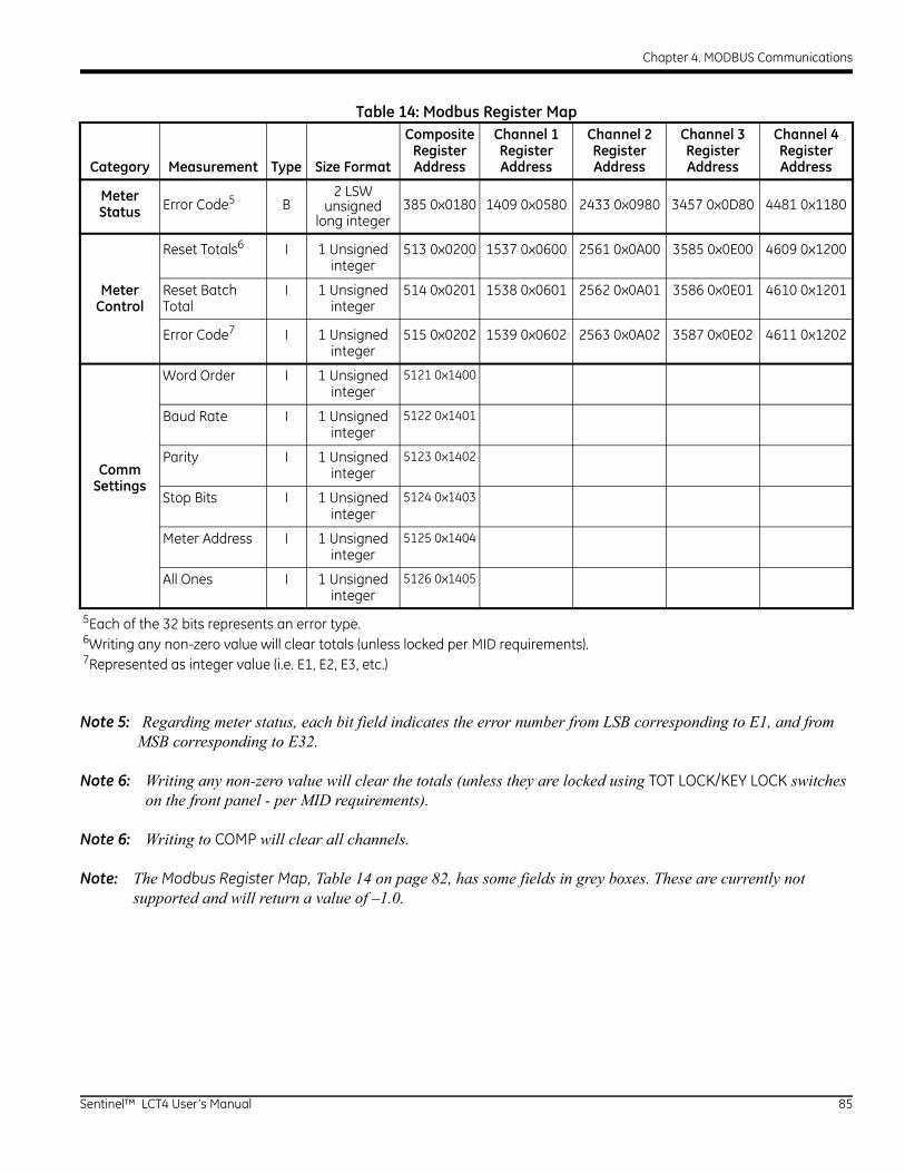
Chapter 4. MODBUS Communications
Note 5: Regarding meter status, each bit field indicates the error number from LSB corresponding to E1, and from MSB corresponding to E32.
Note 6: Writing any non-zero value will clear the totals (unless they are locked using TOT LOCK/KEY LOCK switches on the front panel - per MID requirements).
Note 6: Writing to COMP will clear all channels.
Note: The Modbus Register Map, Table 14 on page 82, has some fields in grey boxes. These are currently not supported and will return a value of –1.0.
Meter Status Error Code5 B
2 LSW unsigned
long integer385 0x0180 1409 0x0580 2433 0x0980 3457 0x0D80 4481 0x1180
Reset Totals6 I 1 Unsigned integer
513 0x0200 1537 0x0600 2561 0x0A00 3585 0x0E00 4609 0x1200
Meter Control
Reset Batch Total
I 1 Unsigned integer
514 0x0201 1538 0x0601 2562 0x0A01 3586 0x0E01 4610 0x1201
Error Code7 I 1 Unsigned integer
515 0x0202 1539 0x0602 2563 0x0A02 3587 0x0E02 4611 0x1202
Word Order I 1 Unsigned integer
5121 0x1400
Baud Rate I 1 Unsigned integer
5122 0x1401
Comm Settings
Parity I 1 Unsigned integer
5123 0x1402
Stop Bits I 1 Unsigned integer
5124 0x1403
Meter Address I 1 Unsigned integer
5125 0x1404
All Ones I 1 Unsigned integer
5126 0x1405
5Each of the 32 bits represents an error type.6Writing any non-zero value will clear totals (unless locked per MID requirements).7Represented as integer value (i.e. E1, E2, E3, etc.)
Table 14: Modbus Register Map
Category Measurement Type Size Format
Composite Register Address
Channel 1 Register Address
Channel 2 Register Address
Channel 3 Register Address
Channel 4 Register Address
Sentinel™ LCT4 User’s Manual 85

Chapter 4. MODBUS Communications
86 Sentinel™ LCT4 User’s Manual
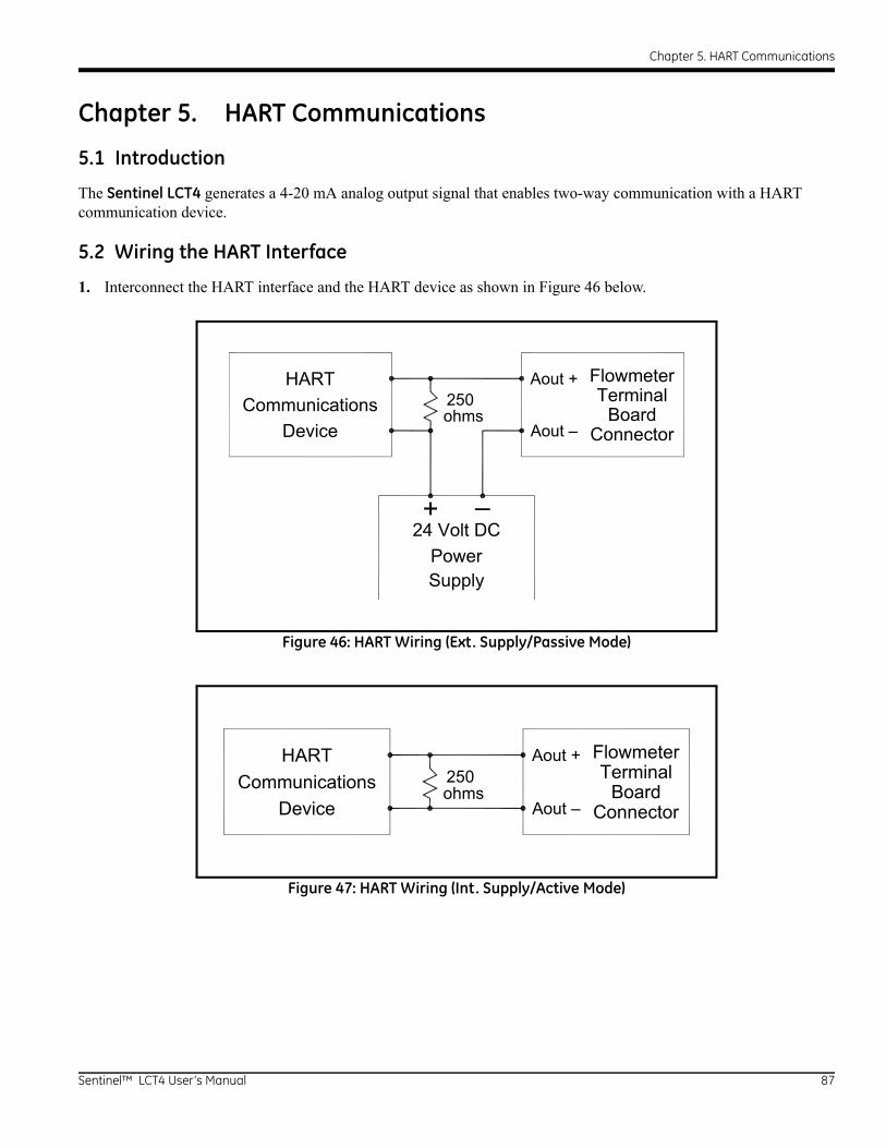
Chapter 5. HART Communications
Chapter 5. HART Communications
5.1 Introduction
The Sentinel LCT4 generates a 4-20 mA analog output signal that enables two-way communication with a HART communication device.
5.2 Wiring the HART Interface
1. Interconnect the HART interface and the HART device as shown in Figure 46 below.
Figure 46: HART Wiring (Ext. Supply/Passive Mode)
Figure 47: HART Wiring (Int. Supply/Active Mode)
HARTCommunications
Device Connector
TerminalFlowmeter
SupplyPower
24 Volt DC+ –
250Boardohms
Aout +
Aout –
HARTCommunications
Device Connector
TerminalFlowmeter
250Boardohms
Aout +
Aout –
Sentinel™ LCT4 User’s Manual 87
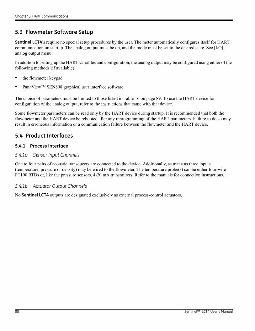
Chapter 5. HART Communications
5.3 Flowmeter Software Setup
Sentinel LCT4’s require no special setup procedures by the user. The meter automatically configures itself for HART communication on startup. The analog output must be on, and the mode must be set to the desired state. See [I/O], analog output menu.
In addition to setting up the HART variables and configuration, the analog output may be configured using either of the following methods (if available):
• the flowmeter keypad
• PanaView™ SEN898 graphical user interface software
The choice of parameters must be limited to those listed in Table 16 on page 89. To use the HART device for configuration of the analog output, refer to the instructions that came with that device.
Some flowmeter parameters can be read only by the HART device during startup. It is recommended that both the flowmeter and the HART device be rebooted after any reprogramming of the HART parameters. Failure to do so may result in erroneous information or a communication failure between the flowmeter and the HART device.
5.4 Product Interfaces
5.4.1 Process Interface
5.4.1a Sensor Input Channels
One to four pairs of acoustic transducers are connected to the device. Additionally, as many as three inputs (temperature, pressure or density) may be wired to the flowmeter. The temperature probe(s) can be either four-wire PT100 RTDs or, like the pressure sensors, 4-20 mA transmitters. Refer to the manuals for connection instructions.
5.4.1b Actuator Output Channels
No Sentinel LCT4 outputs are designated exclusively as external process-control actuators.
88 Sentinel™ LCT4 User’s Manual
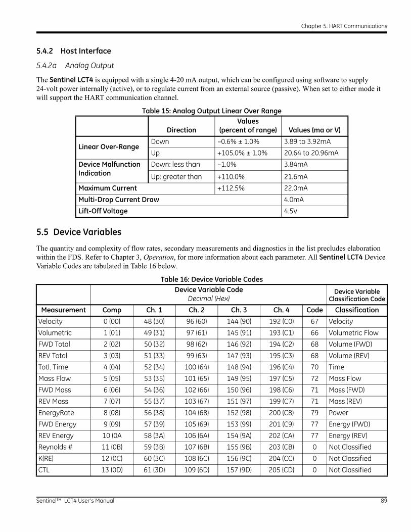
Chapter 5. HART Communications
5.4.2 Host Interface
5.4.2a Analog Output
The Sentinel LCT4 is equipped with a single 4-20 mA output, which can be configured using software to supply 24-volt power internally (active), or to regulate current from an external source (passive). When set to either mode it will support the HART communication channel.
5.5 Device Variables
The quantity and complexity of flow rates, secondary measurements and diagnostics in the list precludes elaboration within the FDS. Refer to Chapter 3, Operation, for more information about each parameter. All Sentinel LCT4 Device Variable Codes are tabulated in Table 16 below.
Table 15: Analog Output Linear Over Range
DirectionValues
(percent of range) Values (ma or V)
Linear Over-Range
Down –0.6% ± 1.0% 3.89 to 3.92mA
Up +105.0% ± 1.0% 20.64 to 20.96mA
Device Malfunction Indication
Down: less than –1.0% 3.84mA
Up: greater than +110.0% 21.6mA
Maximum Current +112.5% 22.0mA
Multi-Drop Current Draw 4.0mA
Lift-Off Voltage 4.5V
Table 16: Device Variable CodesDevice Variable Code
Decimal (Hex)Device Variable
Classification Code
Measurement Comp Ch. 1 Ch. 2 Ch. 3 Ch. 4 Code Classification
Velocity 0 (00) 48 (30) 96 (60) 144 (90) 192 (C0) 67 Velocity
Volumetric 1 (01) 49 (31) 97 (61) 145 (91) 193 (C1) 66 Volumetric Flow
FWD Total 2 (02) 50 (32) 98 (62) 146 (92) 194 (C2) 68 Volume (FWD)
REV Total 3 (03) 51 (33) 99 (63) 147 (93) 195 (C3) 68 Volume (REV)
Totl. Time 4 (04) 52 (34) 100 (64) 148 (94) 196 (C4) 70 Time
Mass Flow 5 (05) 53 (35) 101 (65) 149 (95) 197 (C5) 72 Mass Flow
FWD Mass 6 (06) 54 (36) 102 (66) 150 (96) 198 (C6) 71 Mass (FWD)
REV Mass 7 (07) 55 (37) 103 (67) 151 (97) 199 (C7) 71 Mass (REV)
EnergyRate 8 (08) 56 (38) 104 (68) 152 (98) 200 (C8) 79 Power
FWD Energy 9 (09) 57 (39) 105 (69) 153 (99) 201 (C9) 77 Energy (FWD)
REV Energy 10 (0A 58 (3A) 106 (6A) 154 (9A) 202 (CA) 77 Energy (REV)
Reynolds # 11 (0B) 59 (3B) 107 (6B) 155 (9B) 203 (CB) 0 Not Classified
K(RE) 12 (0C) 60 (3C) 108 (6C) 156 (9C) 204 (CC) 0 Not Classified
CTL 13 (0D) 61 (3D) 109 (6D) 157 (9D) 205 (CD) 0 Not Classified
Sentinel™ LCT4 User’s Manual 89

Chapter 5. HART Communications
CPL 14 (0E) 62 (3E) 110 (6E) 158 (9E) 206 (CE) 0 Not Classified
CTPL 15 (0F) 63 (3F) 111 (6F) 159 (9F) 207 (CF) 0 Not Classified
Soundspeed 16 (10) 64 (40) 112 (70) 160 (A0) 208 (D0) 67 Velocity
Up Transit 17 (11) 65 (41) 113 (71) 161 (A1) 209 (D1) 70 Time
Dn Transit 18 (12) 66 (42) 114 (72) 162 (A2) 210 (D2) 70 Time
DeltaT 19 (13) 67 (43) 115 (73) 163 (A3) 211 (D3) 70 Time
Gain Up[dB] 20 (14) 68 (44) 116 (74) 164 (A4) 212 (D4) 0 Not Classified
Gain Dn[db] 21 (15) 69 (45) 117 (75) 165 (A5) 213 (D5) 0 Not Classified
Up Sig Strength 22 (16) 70 (46) 118 (76) 166 (A6) 214 (D6) 0 Not Classified
DN Sig Strength 23 (17) 71 (47) 119 (77) 167 (A7) 215 (D7) 0 Not Classified
UP DAC 24 (18) 72 (48) 120 (78) 168 (A8) 216 (D8) 0 Not Classified
DN DAC 25 (19) 73 (49) 121 (79) 169 (A9) 217 (D9) 0 Not Classified
UP Amp Discrim 26 (1A) 74 (4A) 122 (7A) 170 (AA) 218 (DA) 0 Not Classified
DN Amp Discrim 27 (1B) 75 (4B) 123 (7B) 171 (AB) 219 (DB) 0 Not Classified
Peak% 28 (1C) 76 (4C) 124 (7C) 172 (AC) 220 (DC) 81 Analytical
UP Signal Q 29 (1D) 77 (4D) 125 (7D) 173 (AD) 221 (DD) 0 Not Classified
DN Signal Q 30 (1E) 78 (4E) 126 (7E) 174 (AE) 222 (DE) 0 Not Classified
UP +– Peak 31 (1F) 79 (4F) 127 (7F) 175 (AF) 223 (DF) 0 Not Classified
DN +– Peak 32 (20) 80 (50) 128 (80) 176 (B0) 224 (E0) 0 Not Classified
UP Norm Factor 33 (21) 81 (51) 129 (81) 177 (B1) 225 (E1) 0 Not Classified
DN Norm Factor 34 (22) 82 (52) 130 (82) 178 (B2) 226 (E2) 0 Not Classified
Theta 3 35 (23) 83 (53) 131 (83) 179 (B3) 227 (E3) 0 Not Classified
CEE1 36 (24) 84 (54) 132 (84) 180 (B4) 228 (E4) 67 Velocity
Supply Temp 37 (25) 85 (55) 133 (85) 181 (B5) 229 (E5) 64 Temperature
Return Temp 38 (26) 86 (56) 134 (86) 182 (B6) 230 (E6) 64 Temperature
Supply-Rtn 39 (27) 87 (57) 135 (87) 183 (B7) 231 (E7) 0 Not Classified
Supply Dens 40 (28) 88 (58) 136 (88) 184 (B8) 232 (E8) 0 Not Classified
Return Dens 41 (29) 89 (59) 137 (89) 185 (B9) 233 (E9) 0 Not Classified
Delta h 42 (2A) 90 (5A) 138 (8A) 186 (BA) 234 (EA) 0 Not Classified
Pressure Input 43 (2B) 91 (5B) 139 (8B) 187 (BB) 235 (EB) 65 Pressure
Special Input 1 44 (2C) 92 (5C) 140 (8C) 188 (BC) 236 (EC) 0 Not Classified
Special Input 2 45 (2D) 93 (5D) 141 (8D) 189 (BD) 237 (ED) 0 Not Classified
Special Input 3 46 (2E) 94 (5E) 142 (8E) 190 (BE) 238 (EE) 0 Not Classified
Special Input 4 47 (2F) 95 (5F) 143 (8F) 191 (BF) 239 (EF) 0 Not Classified
Table 16: Device Variable CodesDevice Variable Code
Decimal (Hex)Device Variable
Classification Code
Measurement Comp Ch. 1 Ch. 2 Ch. 3 Ch. 4 Code Classification
90 Sentinel™ LCT4 User’s Manual
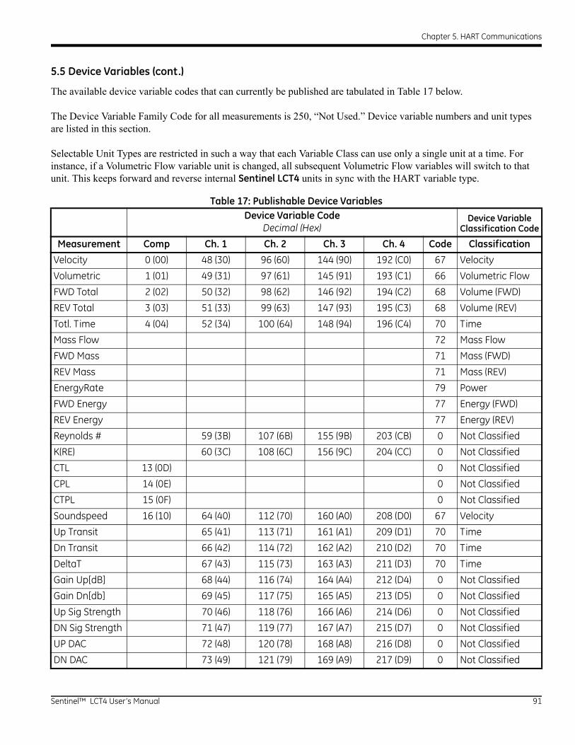
Chapter 5. HART Communications
5.5 Device Variables (cont.)
The available device variable codes that can currently be published are tabulated in Table 17 below.
The Device Variable Family Code for all measurements is 250, “Not Used.” Device variable numbers and unit types are listed in this section.
Selectable Unit Types are restricted in such a way that each Variable Class can use only a single unit at a time. For instance, if a Volumetric Flow variable unit is changed, all subsequent Volumetric Flow variables will switch to that unit. This keeps forward and reverse internal Sentinel LCT4 units in sync with the HART variable type.
Table 17: Publishable Device VariablesDevice Variable Code
Decimal (Hex)Device Variable
Classification Code
Measurement Comp Ch. 1 Ch. 2 Ch. 3 Ch. 4 Code Classification
Velocity 0 (00) 48 (30) 96 (60) 144 (90) 192 (C0) 67 Velocity
Volumetric 1 (01) 49 (31) 97 (61) 145 (91) 193 (C1) 66 Volumetric Flow
FWD Total 2 (02) 50 (32) 98 (62) 146 (92) 194 (C2) 68 Volume (FWD)
REV Total 3 (03) 51 (33) 99 (63) 147 (93) 195 (C3) 68 Volume (REV)
Totl. Time 4 (04) 52 (34) 100 (64) 148 (94) 196 (C4) 70 Time
Mass Flow 72 Mass Flow
FWD Mass 71 Mass (FWD)
REV Mass 71 Mass (REV)
EnergyRate 79 Power
FWD Energy 77 Energy (FWD)
REV Energy 77 Energy (REV)
Reynolds # 59 (3B) 107 (6B) 155 (9B) 203 (CB) 0 Not Classified
K(RE) 60 (3C) 108 (6C) 156 (9C) 204 (CC) 0 Not Classified
CTL 13 (0D) 0 Not Classified
CPL 14 (0E) 0 Not Classified
CTPL 15 (0F) 0 Not Classified
Soundspeed 16 (10) 64 (40) 112 (70) 160 (A0) 208 (D0) 67 Velocity
Up Transit 65 (41) 113 (71) 161 (A1) 209 (D1) 70 Time
Dn Transit 66 (42) 114 (72) 162 (A2) 210 (D2) 70 Time
DeltaT 67 (43) 115 (73) 163 (A3) 211 (D3) 70 Time
Gain Up[dB] 68 (44) 116 (74) 164 (A4) 212 (D4) 0 Not Classified
Gain Dn[db] 69 (45) 117 (75) 165 (A5) 213 (D5) 0 Not Classified
Up Sig Strength 70 (46) 118 (76) 166 (A6) 214 (D6) 0 Not Classified
DN Sig Strength 71 (47) 119 (77) 167 (A7) 215 (D7) 0 Not Classified
UP DAC 72 (48) 120 (78) 168 (A8) 216 (D8) 0 Not Classified
DN DAC 73 (49) 121 (79) 169 (A9) 217 (D9) 0 Not Classified
Sentinel™ LCT4 User’s Manual 91
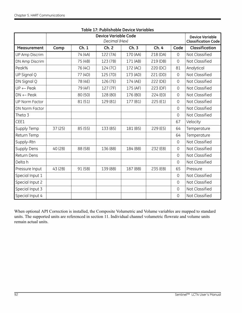
Chapter 5. HART Communications
When optional API Correction is installed, the Composite Volumetric and Volume variables are mapped to standard units. The supported units are referenced in section 11. Individual channel volumetric flowrate and volume units remain actual units.
UP Amp Discrim 74 (4A) 122 (7A) 170 (AA) 218 (DA) 0 Not Classified
DN Amp Discrim 75 (4B) 123 (7B) 171 (AB) 219 (DB) 0 Not Classified
Peak% 76 (4C) 124 (7C) 172 (AC) 220 (DC) 81 Analytical
UP Signal Q 77 (4D) 125 (7D) 173 (AD) 221 (DD) 0 Not Classified
DN Signal Q 78 (4E) 126 (7E) 174 (AE) 222 (DE) 0 Not Classified
UP +– Peak 79 (4F) 127 (7F) 175 (AF) 223 (DF) 0 Not Classified
DN +– Peak 80 (50) 128 (80) 176 (B0) 224 (E0) 0 Not Classified
UP Norm Factor 81 (51) 129 (81) 177 (B1) 225 (E1) 0 Not Classified
DN Norm Factor 0 Not Classified
Theta 3 0 Not Classified
CEE1 67 Velocity
Supply Temp 37 (25) 85 (55) 133 (85) 181 (B5) 229 (E5) 64 Temperature
Return Temp 64 Temperature
Supply-Rtn 0 Not Classified
Supply Dens 40 (28) 88 (58) 136 (88) 184 (B8) 232 (E8) 0 Not Classified
Return Dens 0 Not Classified
Delta h 0 Not Classified
Pressure Input 43 (2B) 91 (5B) 139 (8B) 187 (BB) 235 (EB) 65 Pressure
Special Input 1 0 Not Classified
Special Input 2 0 Not Classified
Special Input 3 0 Not Classified
Special Input 4 0 Not Classified
Table 17: Publishable Device VariablesDevice Variable Code
Decimal (Hex)Device Variable
Classification Code
Measurement Comp Ch. 1 Ch. 2 Ch. 3 Ch. 4 Code Classification
92 Sentinel™ LCT4 User’s Manual
Chapter 5. HART Communications
5.6 Dynamic Variables
Only certain device variables can be published and are listed in Table 17 above. More publishable variables may be added as the capabilities are added to the meter. Only the device variables listed in Table 17 may be assigned as primary, secondary, tertiary or quaternary variables (PV, SV, TV and QV). Certain diagnostic variables have units specific to that diagnostic. Refer to the Sentinel LCT4 for details on the use of diagnostic variables indicated by the variable class specified as “Not Classified.”
5.7 Status Information
5.7.1 Device Status
Bit 4 (“More Status Available”) is set whenever any failure is detected. Command #48 furnishes specific information about the failure. Refer to Section Error! Reference source not found., to the Sentinel LCT4 User’s Manual and to Common Tables Specification Table 17. Due to the large number of device variables, the Non-Primary Variable Out of Limits flag bit, Table 12, section 7.4.3 HCF_SPEC-99, is never set. Instead, monitor the Extended Device Status to determine overall device variable status.
Bit 1 (“Non-Primary variable out of limits”) is set only when any of the SV, TV or QV variables are out of their respective limits. This bit is not set for variables not mapped to the SV, TV or QV.
5.7.2 Extended Device Status
Extended Device Code 0x01, Maintenance Required, is never set by the Sentinel LCT4.
Code 0x02, Device Variable Alert, is set if the meter is in an alarm or warning state. Because of the complexity of meter configuration and flow computation, the SEN898 may not set Device Variable Status indicators to identify specific Device Variables as the cause of the alert. Refer to the manual for information about “flow” and “non-flow” errors.
Sentinel™ LCT4 User’s Manual 93
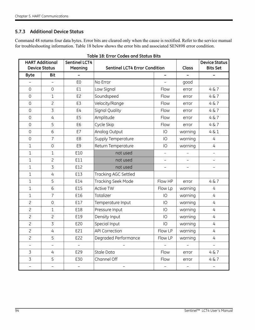
Chapter 5. HART Communications
5.7.3 Additional Device Status
Command 48 returns four data bytes. Error bits are cleared only when the cause is rectified. Refer to the service manual for troubleshooting information. Table 18 below shows the error bits and associated SEN898 error condition.
Table 18: Error Codes and Status BitsHART Additional
Device StatusSentinel LCT4
Meaning Sentinel LCT4 Error Condition ClassDevice Status
Bits Set
Byte Bit – – – –
– – E0 No Error – good
0 0 E1 Low Signal Flow error 4 & 7
0 1 E2 Soundspeed Flow error 4 & 7
0 2 E3 Velocity/Range Flow error 4 & 7
0 3 E4 Signal Quality Flow error 4 & 7
0 4 E5 Amplitude Flow error 4 & 7
0 5 E6 Cycle Skip Flow error 4 & 7
0 6 E7 Analog Output IO warning 4 & 1
0 7 E8 Supply Temperature IO warning 4
1 0 E9 Return Temperature IO warning 4
1 1 E10 not used – – –
1 2 E11 not used – – –
1 3 E12 not used – – –
1 4 E13 Tracking AGC Settled
1 5 E14 Tracking Seek Mode Flow HP error 4 & 7
1 6 E15 Active TW Flow Lp warning 4
1 7 E16 Totalizer IO warning 4
2 0 E17 Temperature Input IO warning 4
2 1 E18 Pressure Input IO warning 4
2 2 E19 Density Input IO warning 4
2 3 E20 Special Input IO warning 4
2 4 E21 API Correction Flow LP warning 4
2 5 E22 Degraded Performance Flow LP warning 4
– – – – – – –
3 4 E29 Stale Data Flow error 4 & 7
3 5 E30 Channel Off Flow error 4 & 7
– – – – – – –
94 Sentinel™ LCT4 User’s Manual
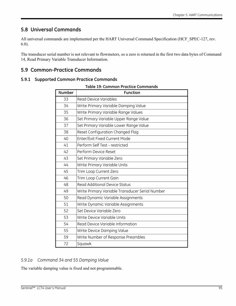
Chapter 5. HART Communications
5.8 Universal Commands
All universal commands are implemented per the HART Universal Command Specification (HCF_SPEC-127, rev. 6.0).
The transducer serial number is not relevant to flowmeters, so a zero is returned in the first two data bytes of Command 14, Read Primary Variable Transducer Information.
5.9 Common-Practice Commands
5.9.1 Supported Common Practice Commands
5.9.1a Command 34 and 55 Damping Value
The variable damping value is fixed and not programmable.
Table 19: Common Practice CommandsNumber Function
33 Read Device Variables
34 Write Primary Variable Damping Value
35 Write Primary Variable Range Values
36 Set Primary Variable Upper Range Value
37 Set Primary Variable Lower Range Value
38 Reset Configuration Changed Flag
40 Enter/Exit Fixed Current Mode
41 Perform Self Test - restricted
42 Perform Device Reset
43 Set Primary Variable Zero
44 Write Primary Variable Units
45 Trim Loop Current Zero
46 Trim Loop Current Gain
48 Read Additional Device Status
49 Write Primary Variable Transducer Serial Number
50 Read Dynamic Variable Assignments
51 Write Dynamic Variable Assignments
52 Set Device Variable Zero
53 Write Device Variable Units
54 Read Device Variable Information
55 Write Device Damping Value
59 Write Number of Response Preambles
72 Squawk
Sentinel™ LCT4 User’s Manual 95
Chapter 5. HART Communications
5.9.1b Command 35 Units Restriction
Command 35 does not allow range to be set with units other than the current publishing units. If the units do not match the selected Primary Variable units, the response “Invalid Selection” is returned. The meter does not provide the capability to convert values between units in Command 35.
5.9.1c Command 41 Perform Self Test
Due to the complex nature of the SEN898SEN898 meter, the self-test mode is Restricted. However, the device status is constantly monitored and Command 48, Read Additional Device Status, should be used to determine the current state of the meter.
5.9.1d Command 43 Set Primary Variable Zero
Only the Totals variable can be set to Zero with this command. Any other variable that is not a Forward or Reverse Total will return Invalid Selection.
5.9.1e Command 72 Squawk Command
The Squawk function, command 72, causes the LCD backlight to flash.
5.9.1f Command 52 Set Device Variable Zero
This is the same as the Device Specific command 181: Clear Totals, if the variable specified is a Totals variable. Any totals variable specified with this command will affect all totals variables. This command does not affect variables that are not a Totals variable. Invalid selection is returned for non-totals variables.
5.9.2 Burst Mode Commands
The Sentinel LCT4 does not support burst mode.
5.9.3 Catch Device Variable Command
The Sentinel LCT4 does not support the catch device variable mechanism.
96 Sentinel™ LCT4 User’s Manual
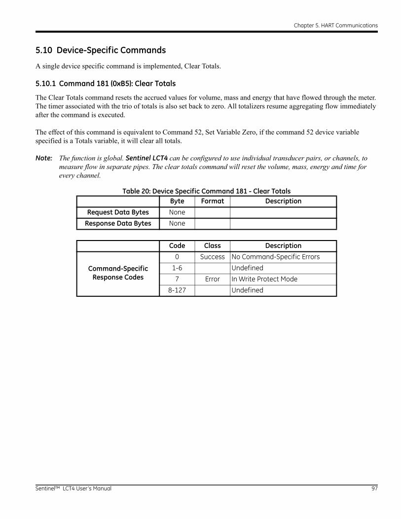
Chapter 5. HART Communications
5.10 Device-Specific Commands
A single device specific command is implemented, Clear Totals.
5.10.1 Command 181 (0xB5): Clear Totals
The Clear Totals command resets the accrued values for volume, mass and energy that have flowed through the meter. The timer associated with the trio of totals is also set back to zero. All totalizers resume aggregating flow immediately after the command is executed.
The effect of this command is equivalent to Command 52, Set Variable Zero, if the command 52 device variable specified is a Totals variable, it will clear all totals.
Note: The function is global. Sentinel LCT4 can be configured to use individual transducer pairs, or channels, to measure flow in separate pipes. The clear totals command will reset the volume, mass, energy and time for every channel.
Table 20: Device Specific Command 181 - Clear TotalsByte Format Description
Request Data Bytes None
Response Data Bytes None
Code Class Description
Command-SpecificResponse Codes
0 Success No Command-Specific Errors
1-6 Undefined
7 Error In Write Protect Mode
8-127 Undefined
Sentinel™ LCT4 User’s Manual 97
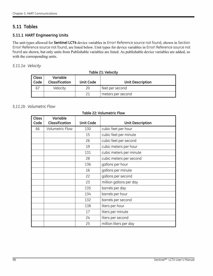
Chapter 5. HART Communications
5.11 Tables
5.11.1 HART Engineering Units
The unit types allowed for Sentinel LCT4 device variables in Error! Reference source not found, shown in Section Error! Reference source not found, are listed below. Unit types for device variables in Error! Reference source not found are shown, but only units from Publishable variables are listed. As publishable device variables are added, so with the corresponding units.
5.11.1a Velocity
5.11.1b Volumetric Flow
Table 21: VelocityClass Code
Variable Classification Unit Code Unit Description
67 Velocity 20 feet per second
21 meters per second
Table 22: Volumetric FlowClass Code
Variable Classification Unit Code Unit Description
66 Volumetric Flow 130 cubic feet per hour
15 cubic feet per minute
26 cubic feet per second
19 cubic meters per hour
131 cubic meters per minute
28 cubic meters per second
136 gallons per hour
16 gallons per minute
22 gallons per second
23 million gallons per day
135 barrels per day
134 barrels per hour
132 barrels per second
138 liters per hour
17 liters per minute
24 liters per second
25 million liters per day
98 Sentinel™ LCT4 User’s Manual
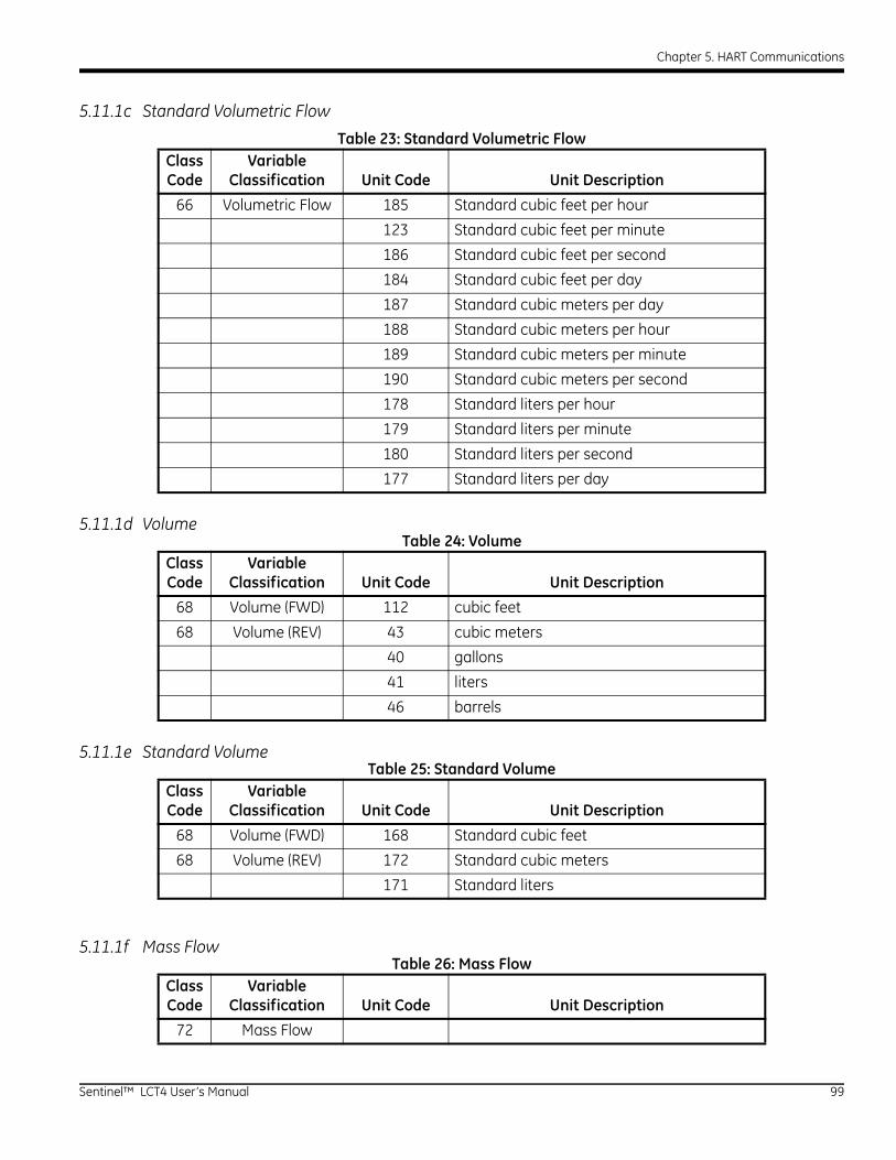
Chapter 5. HART Communications
5.11.1c Standard Volumetric Flow
5.11.1d Volume
5.11.1e Standard Volume
5.11.1f Mass Flow
Table 23: Standard Volumetric FlowClass Code
Variable Classification Unit Code Unit Description
66 Volumetric Flow 185 Standard cubic feet per hour
123 Standard cubic feet per minute
186 Standard cubic feet per second
184 Standard cubic feet per day
187 Standard cubic meters per day
188 Standard cubic meters per hour
189 Standard cubic meters per minute
190 Standard cubic meters per second
178 Standard liters per hour
179 Standard liters per minute
180 Standard liters per second
177 Standard liters per day
Table 24: VolumeClass Code
Variable Classification Unit Code Unit Description
68 Volume (FWD) 112 cubic feet
68 Volume (REV) 43 cubic meters
40 gallons
41 liters
46 barrels
Table 25: Standard VolumeClass Code
Variable Classification Unit Code Unit Description
68 Volume (FWD) 168 Standard cubic feet
68 Volume (REV) 172 Standard cubic meters
171 Standard liters
Table 26: Mass FlowClass Code
Variable Classification Unit Code Unit Description
72 Mass Flow
Sentinel™ LCT4 User’s Manual 99
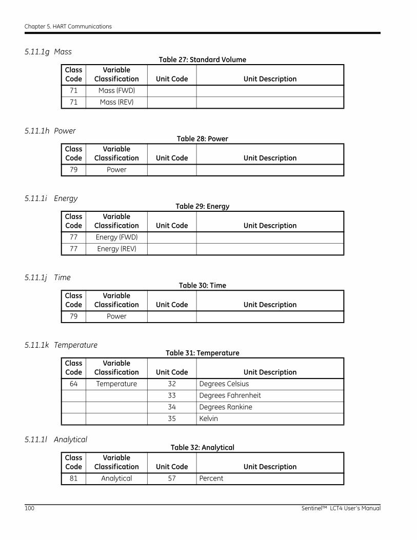
Chapter 5. HART Communications
5.11.1g Mass
5.11.1h Power
5.11.1i Energy
5.11.1j Time
5.11.1k Temperature
5.11.1l Analytical
Table 27: Standard VolumeClass Code
Variable Classification Unit Code Unit Description
71 Mass (FWD)
71 Mass (REV)
Table 28: PowerClass Code
Variable Classification Unit Code Unit Description
79 Power
Table 29: EnergyClass Code
Variable Classification Unit Code Unit Description
77 Energy (FWD)
77 Energy (REV)
Table 30: TimeClass Code
Variable Classification Unit Code Unit Description
79 Power
Table 31: TemperatureClass Code
Variable Classification Unit Code Unit Description
64 Temperature 32 Degrees Celsius
33 Degrees Fahrenheit
34 Degrees Rankine
35 Kelvin
Table 32: AnalyticalClass Code
Variable Classification Unit Code Unit Description
81 Analytical 57 Percent
100 Sentinel™ LCT4 User’s Manual
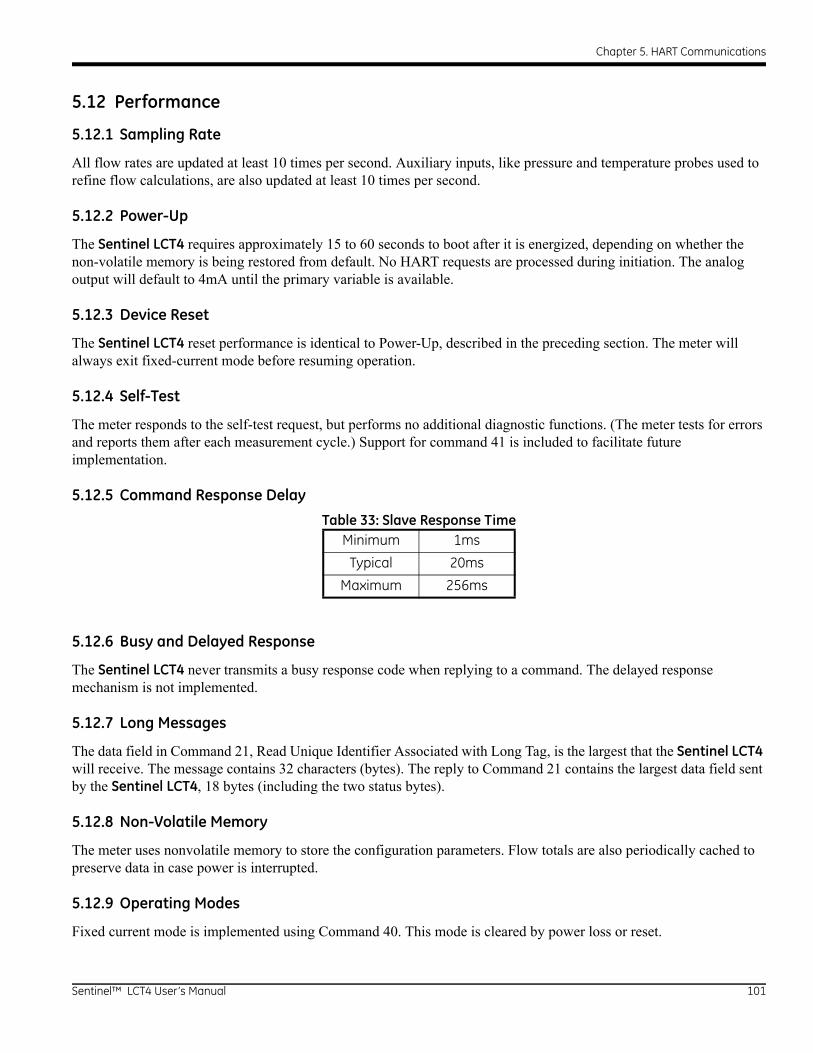
Chapter 5. HART Communications
5.12 Performance
5.12.1 Sampling Rate
All flow rates are updated at least 10 times per second. Auxiliary inputs, like pressure and temperature probes used to refine flow calculations, are also updated at least 10 times per second.
5.12.2 Power-Up
The Sentinel LCT4 requires approximately 15 to 60 seconds to boot after it is energized, depending on whether the non-volatile memory is being restored from default. No HART requests are processed during initiation. The analog output will default to 4mA until the primary variable is available.
5.12.3 Device Reset
The Sentinel LCT4 reset performance is identical to Power-Up, described in the preceding section. The meter will always exit fixed-current mode before resuming operation.
5.12.4 Self-Test
The meter responds to the self-test request, but performs no additional diagnostic functions. (The meter tests for errors and reports them after each measurement cycle.) Support for command 41 is included to facilitate future implementation.
5.12.5 Command Response Delay
5.12.6 Busy and Delayed Response
The Sentinel LCT4 never transmits a busy response code when replying to a command. The delayed response mechanism is not implemented.
5.12.7 Long Messages
The data field in Command 21, Read Unique Identifier Associated with Long Tag, is the largest that the Sentinel LCT4 will receive. The message contains 32 characters (bytes). The reply to Command 21 contains the largest data field sent by the Sentinel LCT4, 18 bytes (including the two status bytes).
5.12.8 Non-Volatile Memory
The meter uses nonvolatile memory to store the configuration parameters. Flow totals are also periodically cached to preserve data in case power is interrupted.
5.12.9 Operating Modes
Fixed current mode is implemented using Command 40. This mode is cleared by power loss or reset.
Table 33: Slave Response TimeMinimum 1ms
Typical 20ms
Maximum 256ms
Sentinel™ LCT4 User’s Manual 101
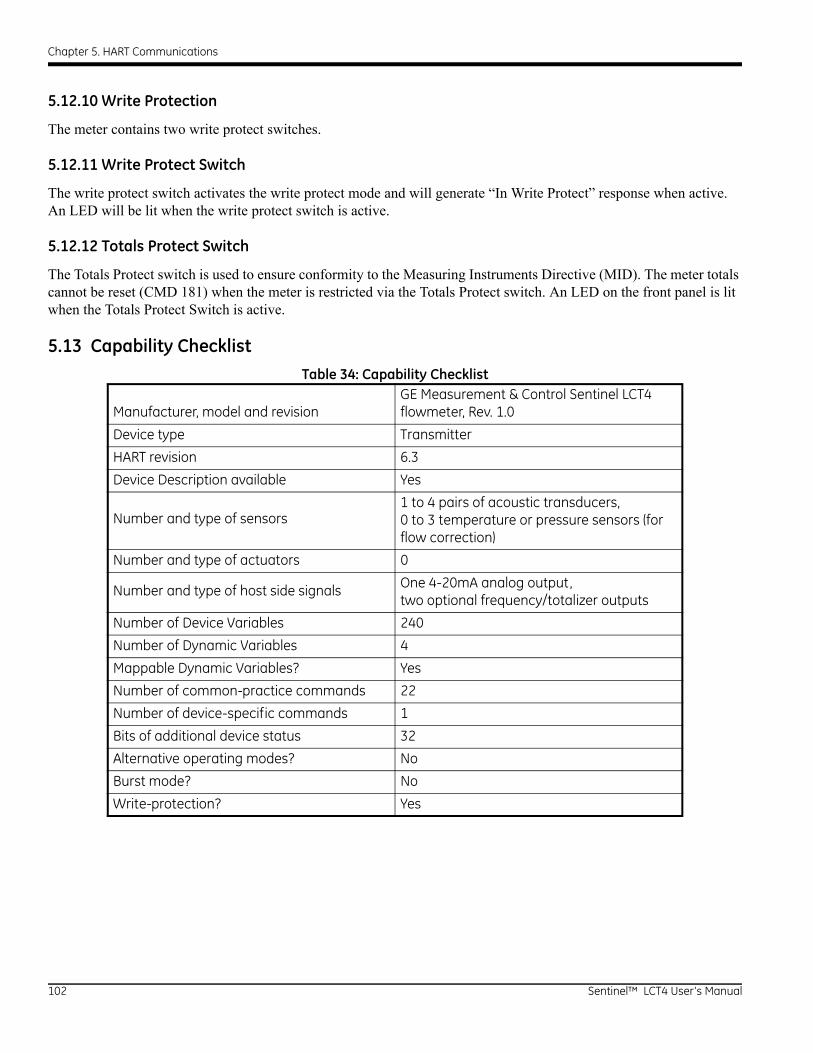
Chapter 5. HART Communications
5.12.10 Write Protection
The meter contains two write protect switches.
5.12.11 Write Protect Switch
The write protect switch activates the write protect mode and will generate “In Write Protect” response when active. An LED will be lit when the write protect switch is active.
5.12.12 Totals Protect Switch
The Totals Protect switch is used to ensure conformity to the Measuring Instruments Directive (MID). The meter totals cannot be reset (CMD 181) when the meter is restricted via the Totals Protect switch. An LED on the front panel is lit when the Totals Protect Switch is active.
5.13 Capability ChecklistTable 34: Capability Checklist
Manufacturer, model and revisionGE Measurement & Control Sentinel LCT4 flowmeter, Rev. 1.0
Device type Transmitter
HART revision 6.3
Device Description available Yes
Number and type of sensors
1 to 4 pairs of acoustic transducers,0 to 3 temperature or pressure sensors (for flow correction)
Number and type of actuators 0
Number and type of host side signals
One 4-20mA analog output,two optional frequency/totalizer outputs
Number of Device Variables 240
Number of Dynamic Variables 4
Mappable Dynamic Variables? Yes
Number of common-practice commands 22
Number of device-specific commands 1
Bits of additional device status 32
Alternative operating modes? No
Burst mode? No
Write-protection? Yes
102 Sentinel™ LCT4 User’s Manual
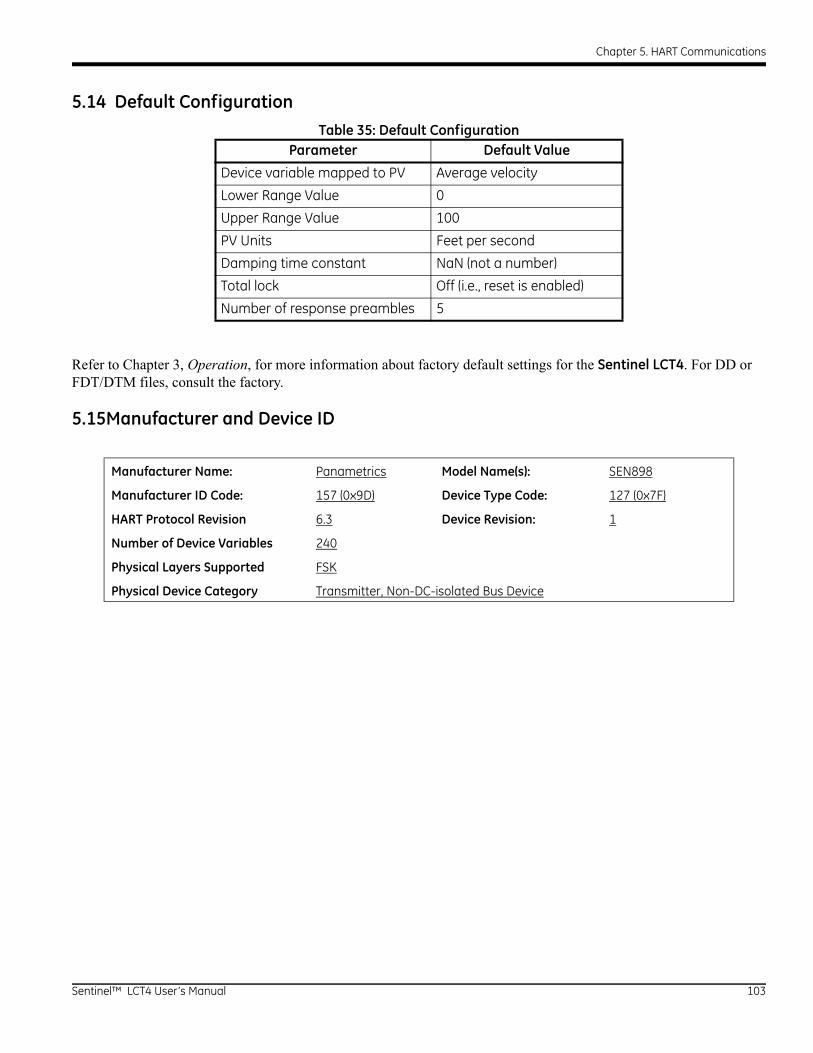
Chapter 5. HART Communications
5.14 Default Configuration
Refer to Chapter 3, Operation, for more information about factory default settings for the Sentinel LCT4. For DD or FDT/DTM files, consult the factory.
5.15Manufacturer and Device ID
Table 35: Default ConfigurationParameter Default Value
Device variable mapped to PV Average velocity
Lower Range Value 0
Upper Range Value 100
PV Units Feet per second
Damping time constant NaN (not a number)
Total lock Off (i.e., reset is enabled)
Number of response preambles 5
Manufacturer Name: Panametrics Model Name(s): SEN898
Manufacturer ID Code: 157 (0x9D) Device Type Code: 127 (0x7F)
HART Protocol Revision 6.3 Device Revision: 1
Number of Device Variables 240
Physical Layers Supported FSK
Physical Device Category Transmitter, Non-DC-isolated Bus Device
Sentinel™ LCT4 User’s Manual 103

Chapter 5. HART Communications
[no content intended for this page]
104 Sentinel™ LCT4 User’s Manual

Chapter 6. Maintenance
Chapter 6. Maintenance
6.1 Calibration
In the CALIB menu, the user can calibrate and trim the analog output and inputs and check other meter functions. This chapter also covers updating Sentinel LCT4 software over the RS232 interface.
Before performing calibration of the Sentinel LCT4, be sure the following equipment is available:
• Current meter capable of precisely measuring 4 to 20 mA current levels
• PC with RS232 Cable and Hyperterminal software (available on Windows operating systems)
While following the programming instructions, refer to Figure 67 on page 139.
6.1.1 Updating Sentinel LCT4 Instrument Software
1. To set up the RS232, connect one end of a 9-pin RS232 cable to the COM-1 serial port on a PC and the other end to Com Port I/O on terminal block TB2 on the Sentinel LCT4, as described in Chapter 2, Installation.
WARNING! Use RS232 connections in Non-Hazardous areas only.
Note: The RS232 cable connection is not limited to the COM-1 serial port of the PC. Connect the RS232 cable to any available RS232 serial port on the PC, and follow the same instructions as for the COM-1 port.
2. On your PC, set up the Hyperterminal program.
Note: The use of Hyperterminal is shown here as an example. If you are using a different communications software, see its manual for detailed instructions.
a. From the PC Start Menu, click Programs/Accessories/Communications/Hyperterminal to open the Hyperterminal window.
b. If the call is not connected, click on New Connection and enter a name. Click OK.
c. In the Connect To window, select COM 1 as the desired port.
d. In the Properties window, set the following parameters:
• Bits per second: 115200
• Data bits: 8
• Parity: None.
• Stop Bits: 1
• Flow control: None
Sentinel™ LCT4 User’s Manual 105
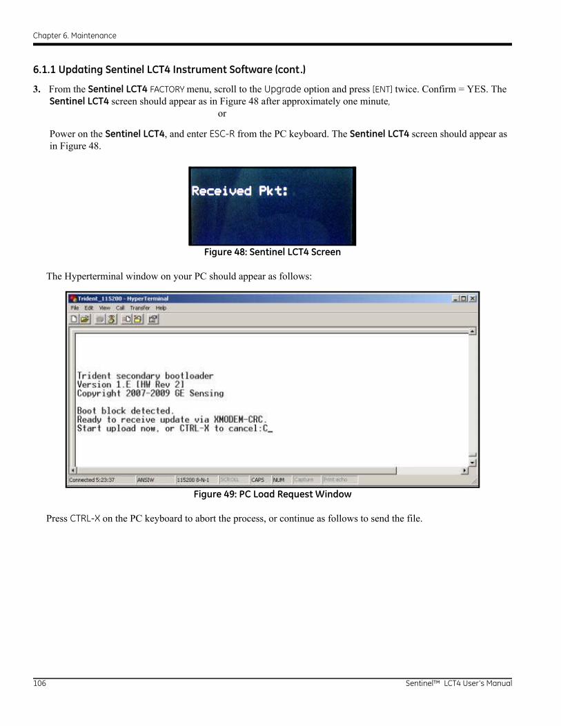
Chapter 6. Maintenance
6.1.1 Updating Sentinel LCT4 Instrument Software (cont.)
3. From the Sentinel LCT4 FACTORY menu, scroll to the Upgrade option and press [ENT] twice. Confirm = YES. The Sentinel LCT4 screen should appear as in Figure 48 after approximately one minute, or
Power on the Sentinel LCT4, and enter ESC-R from the PC keyboard. The Sentinel LCT4 screen should appear as in Figure 48.
Figure 48: Sentinel LCT4 Screen
The Hyperterminal window on your PC should appear as follows:
Figure 49: PC Load Request Window
Press CTRL-X on the PC keyboard to abort the process, or continue as follows to send the file.
106 Sentinel™ LCT4 User’s Manual
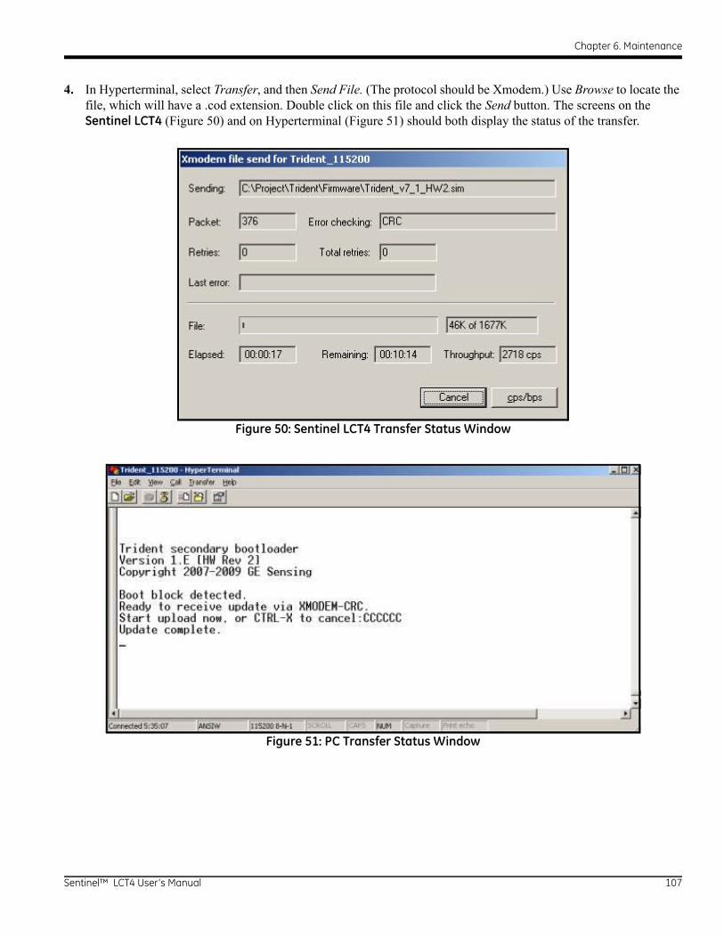
Chapter 6. Maintenance
4. In Hyperterminal, select Transfer, and then Send File. (The protocol should be Xmodem.) Use Browse to locate the file, which will have a .cod extension. Double click on this file and click the Send button. The screens on the Sentinel LCT4 (Figure 50) and on Hyperterminal (Figure 51) should both display the status of the transfer.
Figure 50: Sentinel LCT4 Transfer Status Window
Figure 51: PC Transfer Status Window
Sentinel™ LCT4 User’s Manual 107

Chapter 6. Maintenance
6.1.1 Updating Sentinel LCT4 Instrument Software (cont.)
5. To ensure the Sentinel LCT4 operates correctly, GE recommends defaulting the meter after software updates. From the Sentinel LCT4 Factory Menu, scroll to Default Meter and press [ENT]. Press the up arrow key [] and press [ENT] twice, or at power on, press and hold the [CLR-TOT] key until the following screen appears after several seconds. Release the key. Press the up arrow key [] to default the meter, or the down arrow key [] to cancel the default.
CAUTION! All site configuration and calibration data will be lost if the meter is defaulted. It is highly recommended that a site archive is captured via PanaView SEN898 or using Site File Menu under the Factory Menu and restored after default is complete!
Figure 52: Default Meter? Screen
Note: After the Sentinel LCT4 has been defaulted, it restarts in the locked mode. See page 62 for instructions on unlocking the meter.
6. To check that the software has been loaded correctly, proceed to the next section.
108 Sentinel™ LCT4 User’s Manual
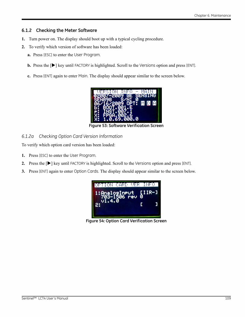
Chapter 6. Maintenance
6.1.2 Checking the Meter Software
1. Turn power on. The display should boot up with a typical cycling procedure.
2. To verify which version of software has been loaded:
a. Press [ESC] to enter the User Program.
b. Press the [] key until FACTORY is highlighted. Scroll to the Versions option and press [ENT].
c. Press [ENT] again to enter Main. The display should appear similar to the screen below.
Figure 53: Software Verification Screen
6.1.2a Checking Option Card Version Information
To verify which option card version has been loaded:
1. Press [ESC] to enter the User Program.
2. Press the [] key until FACTORY is highlighted. Scroll to the Versions option and press [ENT].
3. Press [ENT] again to enter Option Cards. The display should appear similar to the screen below.
Figure 54: Option Card Verification Screen
Sentinel™ LCT4 User’s Manual 109
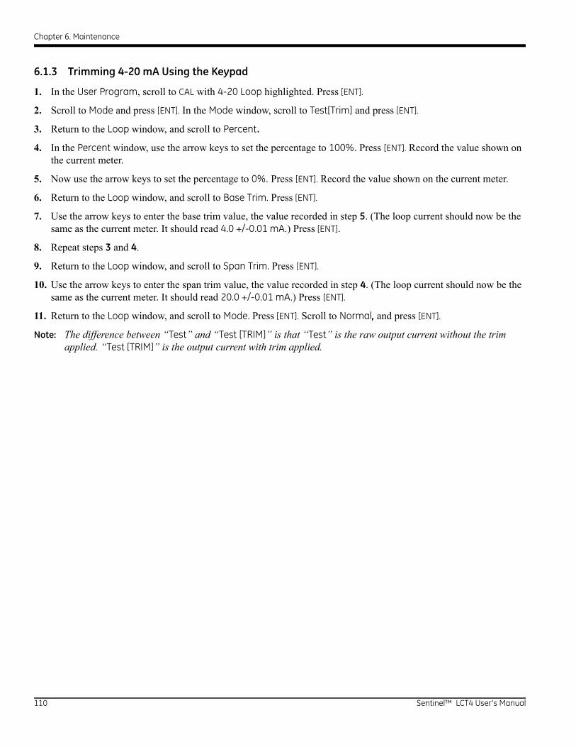
Chapter 6. Maintenance
6.1.3 Trimming 4-20 mA Using the Keypad
1. In the User Program, scroll to CAL with 4-20 Loop highlighted. Press [ENT].
2. Scroll to Mode and press [ENT]. In the Mode window, scroll to Test[Trim] and press [ENT].
3. Return to the Loop window, and scroll to Percent.
4. In the Percent window, use the arrow keys to set the percentage to 100%. Press [ENT]. Record the value shown on the current meter.
5. Now use the arrow keys to set the percentage to 0%. Press [ENT]. Record the value shown on the current meter.
6. Return to the Loop window, and scroll to Base Trim. Press [ENT].
7. Use the arrow keys to enter the base trim value, the value recorded in step 5. (The loop current should now be the same as the current meter. It should read 4.0 +/-0.01 mA.) Press [ENT].
8. Repeat steps 3 and 4.
9. Return to the Loop window, and scroll to Span Trim. Press [ENT].
10. Use the arrow keys to enter the span trim value, the value recorded in step 4. (The loop current should now be the same as the current meter. It should read 20.0 +/-0.01 mA.) Press [ENT].
11. Return to the Loop window, and scroll to Mode. Press [ENT]. Scroll to Normal, and press [ENT].
Note: The difference between “Test” and “Test [TRIM]” is that “Test” is the raw output current without the trim applied. “Test [TRIM]” is the output current with trim applied.
110 Sentinel™ LCT4 User’s Manual

Chapter 6. Maintenance
6.2 Hardware Maintenance and Inspection
WARNING!Before opening the vessel, it must not contain any pressure! This warning pertains to all three interfaces described below (flange interface, transmitter connection and sensor ports). The appropriate procedure should be followed to properly relieve any pressure build up in the system prior to servicing the equipment.
WARNING!All equipment should be de‐energized prior to servicing!
Only trained and qualified personnel should be servicing the pressure vessel. The system has three serviceable interfaces:
• Flanges
• Sensor Ports
• Transmitter Connection
Figure 55: Serviceable Interfaces
TransmitterConnection
Flanges
Sensor Ports
(Hidden)
Sentinel™ LCT4 User’s Manual 111
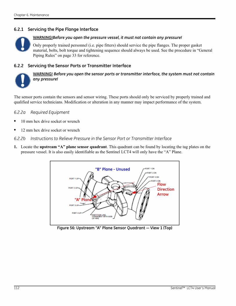
Chapter 6. Maintenance
6.2.1 Servicing the Pipe Flange Interface
WARNING!Before you open the pressure vessel, it must not contain any pressure!
Only properly trained personnel (i.e. pipe fitters) should service the pipe flanges. The proper gasket material, bolts, bolt torque and tightening sequence should always be used. See the procedure in “General Piping Rules” on page 33 for reference.
6.2.2 Servicing the Sensor Ports or Transmitter Interface
WARNING! Before you open the sensor ports or transmitter interface, the system must not contain any pressure!
The sensor ports contain the sensors and sensor wiring. These ports should only be serviced by properly trained and qualified service technicians. Modification or alteration in any manner may impact performance of the system.
6.2.2a Required Equipment
• 10 mm hex drive socket or wrench
• 12 mm hex drive socket or wrench
6.2.2b Instructions to Relieve Pressure in the Sensor Port or Transmitter Interface
1. Locate the upstream “A” plane sensor quadrant. This quadrant can be found by locating the tag plates on the pressure vessel. It is also easily identifiable as the Sentinel LCT4 will only have the “A” Plane.
Figure 56: Upstream “A” Plane Sensor Quadrant — View 1 (Top)
“B” Plane - Unused
FlowDirectionArrow
“A” Plane
112 Sentinel™ LCT4 User’s Manual
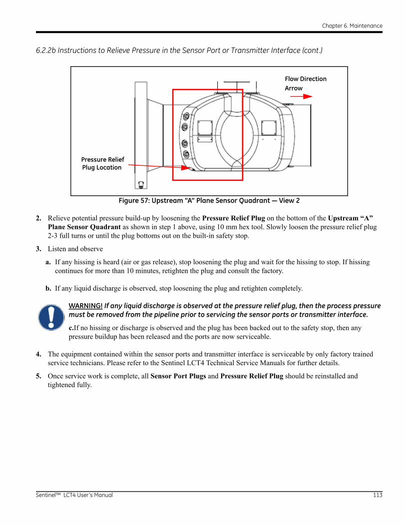
Chapter 6. Maintenance
6.2.2b Instructions to Relieve Pressure in the Sensor Port or Transmitter Interface (cont.)
Figure 57: Upstream “A” Plane Sensor Quadrant — View 2
2. Relieve potential pressure build-up by loosening the Pressure Relief Plug on the bottom of the Upstream “A” Plane Sensor Quadrant as shown in step 1 above, using 10 mm hex tool. Slowly loosen the pressure relief plug 2-3 full turns or until the plug bottoms out on the built-in safety stop.
3. Listen and observe
a. If any hissing is heard (air or gas release), stop loosening the plug and wait for the hissing to stop. If hissing continues for more than 10 minutes, retighten the plug and consult the factory.
b. If any liquid discharge is observed, stop loosening the plug and retighten completely.
WARNING! If any liquid discharge is observed at the pressure relief plug, then the process pressure must be removed from the pipeline prior to servicing the sensor ports or transmitter interface.
c.If no hissing or discharge is observed and the plug has been backed out to the safety stop, then any pressure buildup has been released and the ports are now serviceable.
4. The equipment contained within the sensor ports and transmitter interface is serviceable by only factory trained service technicians. Please refer to the Sentinel LCT4 Technical Service Manuals for further details.
5. Once service work is complete, all Sensor Port Plugs and Pressure Relief Plug should be reinstalled and tightened fully.
Pressure ReliefPlug Location
Flow DirectionArrow
Sentinel™ LCT4 User’s Manual 113

Chapter 6. Maintenance
6.3 Spare Parts
The Sentinel LCT4 is a high-accuracy calibrated flowmeter. Local custody transfer requirements may disallow field replacement of any parts in this flow metering system without a proper calibration of the entire system at an approved calibration facility. Check with local authorities to determine if field replacement of parts is allowed.
If fault is found with the flowmeter electronics, the entire measurement head can be replaced to ensure hardware and firmware compatibility. The replacement part number will be as shown in Sentinel Electronics SEN898 on page 4 of this manual. To ensure that the correct part number is ordered, provide your local GE Measurement & Control representative with the serial number of the meter, located as shown on the “Part String and Serial Number Tag Plate” on page 6.
If it is determined that a flow transducer has been damaged or is faulty, it may also be replaced in the field. Please consult the factory for the appropriate part number.
6.4 Installing Replacement Parts
The Sentinel LCT4 is a high-accuracy calibrated flowmeter. Local custody transfer requirements may disallow field replacement of any parts of this flow metering system without a proper calibration of the entire system at an approved calibration facility. Check with local authorities to determine if field replacement of parts is allowed.
If it is appropriate to replace any component of the flow metering system, the GE Measurement & Control field service team is trained and equipped to perform the replacement on-site. Installation of these field replaceable parts by a GE field service team member will maintain the accuracy of the system and any applicable warranty. Transducer and electronics replacement has been proven to maintain calibration as shown in OIM certificate TC 7595. Please consult the factory to order the appropriate components and to schedule installation in the field.
114 Sentinel™ LCT4 User’s Manual
Chapter 7. Troubleshooting
Chapter 7. Troubleshooting
7.1 Introduction
The Sentinel LCT4 flow transmitter is a reliable, easy to maintain instrument. When properly installed and operated, as described in Chapter 2, Installation, the meter provides accurate flow rate measurements with minimal user intervention. However, if a problem should arise with the electronics enclosure or transducers, this chapter explains how to troubleshoot the Sentinel LCT4. Indications of a possible problem include:
• display of an error message on the LCD screen
• erratic flow readings
• readings of doubtful accuracy (i.e., readings that are not consistent with readings from another flow measuring device connected to the same process).
If any of the above conditions occur, proceed with the instructions presented in this chapter.
Note: For high electrical noise areas, it is recommended to use the CE Installation methods in Appendix B.
7.2 Error Codes
If a problem occurs with the electronics or transducers, a built-in error code message system greatly simplifies the troubleshooting process.
All of the possible Sentinel LCT4 error code messages are discussed in this chapter, along with the possible causes and the recommended actions. When an error code is generated, it will appear in the lower right corner of the LCD screen, as discussed in Chapter 3.
If an error message appears on the display screen during operation of the Sentinel LCT4, refer to the appropriate section of this chapter for instructions on how to proceed. You may be asked to consult the factory. It would be very helpful to capture all of the diagnostic data and parameter information for each channel on the Data Records in Appendix C prior to calling your local sales or service center.
7.2.1 E0: No Error
Problem: No error condition currently exists.
Cause: This message appears briefly to confirm that the response to another error message has corrected the problem.
Action: No action is required.
7.2.2 E1: Low Signal
Problem: Poor ultrasonic signal strength or the signal exceeds the limits entered via the User Program.
Cause: Poor signal strength may be caused by a defective cable, a flowcell problem, a defective transducer or a problem in the electronics console. A signal that exceeds the programmed limits is probably caused by the entry of an improper value in the Error Limits option of the User Program.
Action: Using the procedures in Chapter 1, check the components listed above. Also, check the value entered into the Signal Strength Error Limits option, as described on page 68.
Sentinel™ LCT4 User’s Manual 115
Chapter 7. Troubleshooting
7.2.3 E2: Soundspeed Error
Problem: The soundspeed exceeds the limits programmed in the Error Limits option of the User Program.
Cause: The error may be caused by incorrect programming, poor flow conditions or poor transducer orientation.
Action: Compare the measured soundspeed to tabulated nominal values for the process fluid and correct any programming errors. Refer to the sections on Fluid and Pipe Problems (page 123) and Transducer Problems (page 124) to correct any problems.
7.2.4 E3: Velocity Range Error
Problem: The velocity exceeds the limits programmed in the Error Limits option of the User Program.
Cause: This error may be caused by the entry of improper programming data or by poor flow conditions and/or excessive turbulence.
Action: Make sure the actual flow rate is within the programmed limits. Also, check the value entered into the Error Limits option, as described on page 68. Refer to the sections on Fluid and Pipe Problems (page 123) and on Transducer Problems (page 124) to correct any problems. If this error persists, and no fluid or pipe problems appear to exist, consider enabling the Tracking Windows option.
7.2.5 E4: Signal Quality Error
Problem: The signal quality is outside the limits programmed in the Error Limits option of the User Program.
Cause: The peak of the upstream or downstream correlation signals has fallen below the correlation peak limit, as set in the Error Limits option on page 68. This may be caused by a flowcell or electrical problem.
Action: Consult the factory.
7.2.6 E5: Amplitude Error
Problem: The signal amplitude exceeds the limits programmed in the Error Limits option of the User Program.
Cause: Solid or liquid particulates may be present in the flowcell. The error could also be caused by poor coupling for clamp-on transducers.
Action: Consult the factory.
7.2.7 E6: Cycle Skip, Acceleration Error
Problem: The acceleration exceeds the limits programmed in the Error Limits option of the User Program.
Cause: This condition is usually caused by erratic flow conditions.
Action: Consult the factory.
116 Sentinel™ LCT4 User’s Manual
Chapter 7. Troubleshooting
7.2.8 E7: Analog Output Error
Problem: The current setting is outside the programmed limits.
Cause: The calculated output value exceeds the programmed limits.
Action: Verify that the 4-20 loop configuration base and span settings are correct for the process. Re-range the output if necessary.
7.2.9 E13: Settle Tracking AGC
Problem: The meter is not finding the signal where it is expected.
Cause: The pipe may be empty or actual sound speed is outside of programmed range.
Action: Verify the fluid sound speed settings and fluid type.
7.2.10 E14: Tracking Seek Mode
Problem: The signal is intermittent.
Cause: Discontinuities in fluid characteristics such as multi-phase flow, flashing, pockets of gas, or rapidly changing fluid type make it difficult for the meter to lock in on the signal.
Action: Check the process conditions. If thermal insulation is present, ensure an even application to mitigate hot or cold spots.
7.2.11 E15: Active Tw Error
Problem: The active Tw measurement is outside of the expected range.
Cause: A transducer or cable is damaged, or a transducer needs to be recoupled.
Action: Ensure that the correct transducer is programmed for the meter. If this is not the fault, consult the factory.
7.2.12 E16: Totalizer Overflow Error
Problem: The totalizers are unable to keep up with the total accumulated flow signals.
Cause: The programmed units/pulse value is too small.
Action: Select a larger number of units/pulse value.
7.2.13 E17: Temperature Input Error
Problem: This message indicates a temperature input error.
Cause: The temperature exceeds the specified limits for the analog/RTD inputs, or no input device is connected.
Action: Check the temperature transmitter and the connecting cable. Recalibrate the analog/RTD inputs.
Sentinel™ LCT4 User’s Manual 117

Chapter 7. Troubleshooting
7.2.14 E18: Pressure Input Error
Problem: This message indicates a pressure input error.
Cause: The pressure exceeds the specified limits for the analog inputs, or no input device is connected.
Action: Check the pressure transmitter and the connecting cable. Recalibrate the analog input.
7.2.15 E19: Density Input Error
Problem: This message indicates a density input error.
Cause: The density exceeds the specified limits for the analog inputs, or no input device is connected.
Action: Check the density input device and the connecting cable. Recalibrate the analog input.
7.2.16 E20: Special Input Error
Problem: This message indicates a special input error.
Cause: The special input exceeds the specified limits for the analog inputs, or no input device is connected.
Action: Check the input device and the connecting cable. Recalibrate the analog input.
7.2.17 E21: API Error
Problem: This message indicates an error in the API calculations.
Cause: The combination of pressure, temperature, density, and/or flow inputs causes the calculation to not properly resolve.
Action: The specific API error can be found in the API Info section of the meter's program.
7.2.18 E22: Degraded Performance Error
Problem: The accuracy of the measurement is degraded.
Cause: A loss of one inner and/or outer chord measurement results in the sister inner/outer chord's measurement to be substituted, to provide a flow measurement with degraded accuracy.
Action: Consult the factory.
7.2.19 E23: Reduced Accuracy Error
Problem: The accuracy of the measurement may be reduced.
Cause: The loss of two or more chords of measurement results in chord replacement algorithm to be used, which may introduce additional uncertainty.
Action: Consult the factory.
118 Sentinel™ LCT4 User’s Manual
Chapter 7. Troubleshooting
7.2.20 E24: Low SNR Error
Problem: Signal to Noise lower than recommended units.
Cause: Many possible causes. Check that pipe is full.
Action: Consult factory.
7.2.21 E29: Stale Data Error
Problem: Data internally may be stale.
Cause: Data is stuck in internal state machine.
Action: The conditioning is self-recovering and will automatically correct itself.
7.2.22 E30: Channel Disabled
Problem: The channel is not available.
Cause: The channel has been turned off.
Action: Enter the PROGRAM menu and enable the channel (see Activating a Channel/Path/CHX (Status) on page 65).
Sentinel™ LCT4 User’s Manual 119

Chapter 7. Troubleshooting
7.3 Displaying Diagnostic Parameters
The Sentinel LCT4 offers built-in Diagnostic Parameters to aid in the troubleshooting of transducer and /or electrical problems. These Diagnostics can be set for viewing on the main Display as shown in “Display” on page 78. Some of the available diagnostics are shown in Table 36 below.
You can view multiple diagnostics for all channels by bringing up the Flow Info Form. To access the Flow Info Form, do the following.
1. From the display screen, press [ESC].
Note: You may not be able to reach this with your current security level. You can view Figure 62 in Appendix A to see if your security level has access.
Table 36: Available Diagnostic ParametersOption Bar Description Good Bad
Delta-T[ns] Displays the transit time difference between the upstream and downstream signals. 1 nsec >1 nsec
Amp UpDisplays the value for the signal amplitude of the upstream transducer.
24 ± 5 <14 or >32
Amp DnDisplays the value for the signal amplitude of the downstream transducer.
24 ± 5 <14 or >32
T Up [µs] Displays upstream ultrasonic signal transit time. N.A. N.A.
T Dn [µs] Displays downstream ultrasonic signal transit time. N.A. N.A.
Gain Up [dB] Displays upstream gain in dB. N.A. N.A.
Gain Dn [dB] Displays downstream gain in dB. N.A. N.A.
Signal Up Displays signal strength for the upstream transducer. 50-75 <50 or >75
Signal Dn Displays signal strength for the downstream transducer. 50-75 <50 or >75
Thresh Up [%]Displays the value at which Sentinel LCT4 detects signal arrival time for the upstream transducer.
-100 - +100 <-100 or >100
Thresh Dn [%]Displays value at which Sentinel LCT4 detects signal arrival time for the downstream transducer.
-100 - +100 <-100 or >100
Norm Factor Displays the normalization factor. 0.85 - 1.0 <0.85
P# Up Displays signal peaks for upstream transducer. 100-924 <100 or >924
P# Dn Displays signal peaks for downstream transducer. 100-924 <100 or >924
Quality Up Displays signal quality for upstream transducer. 1200 –400 to +400
Quality Down Displays signal quality for downstream transducer. 1200 –400 to +400
Reynolds # Displays the Reynolds number. N.A. N.A.
k(Re) K factor, based on the Reynolds number. N.A. N.A.
Cycle Time [ms] Time for the reading cycle to complete. N.A. N.A.
KFactor Meter K calibration factor 0.5-2.0 <0.5 or >2.0
#Errors Number of errors present.0<Programmed
Error Limit>Programmed
Error Limit
120 Sentinel™ LCT4 User’s Manual
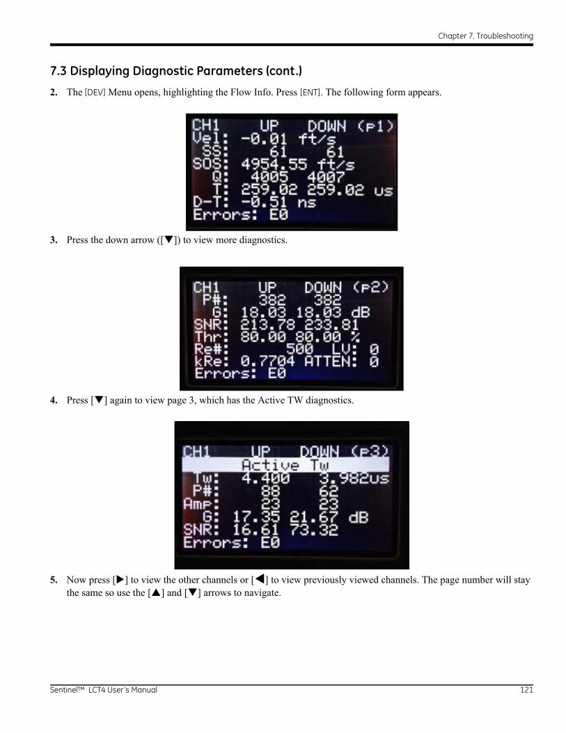
Chapter 7. Troubleshooting
7.3 Displaying Diagnostic Parameters (cont.)
2. The [DEV] Menu opens, highlighting the Flow Info. Press [ENT]. The following form appears.
3. Press the down arrow ([]) to view more diagnostics.
4. Press [] again to view page 3, which has the Active TW diagnostics.
5. Now press [] to view the other channels or [] to view previously viewed channels. The page number will stay the same so use the [] and [] arrows to navigate.
Sentinel™ LCT4 User’s Manual 121
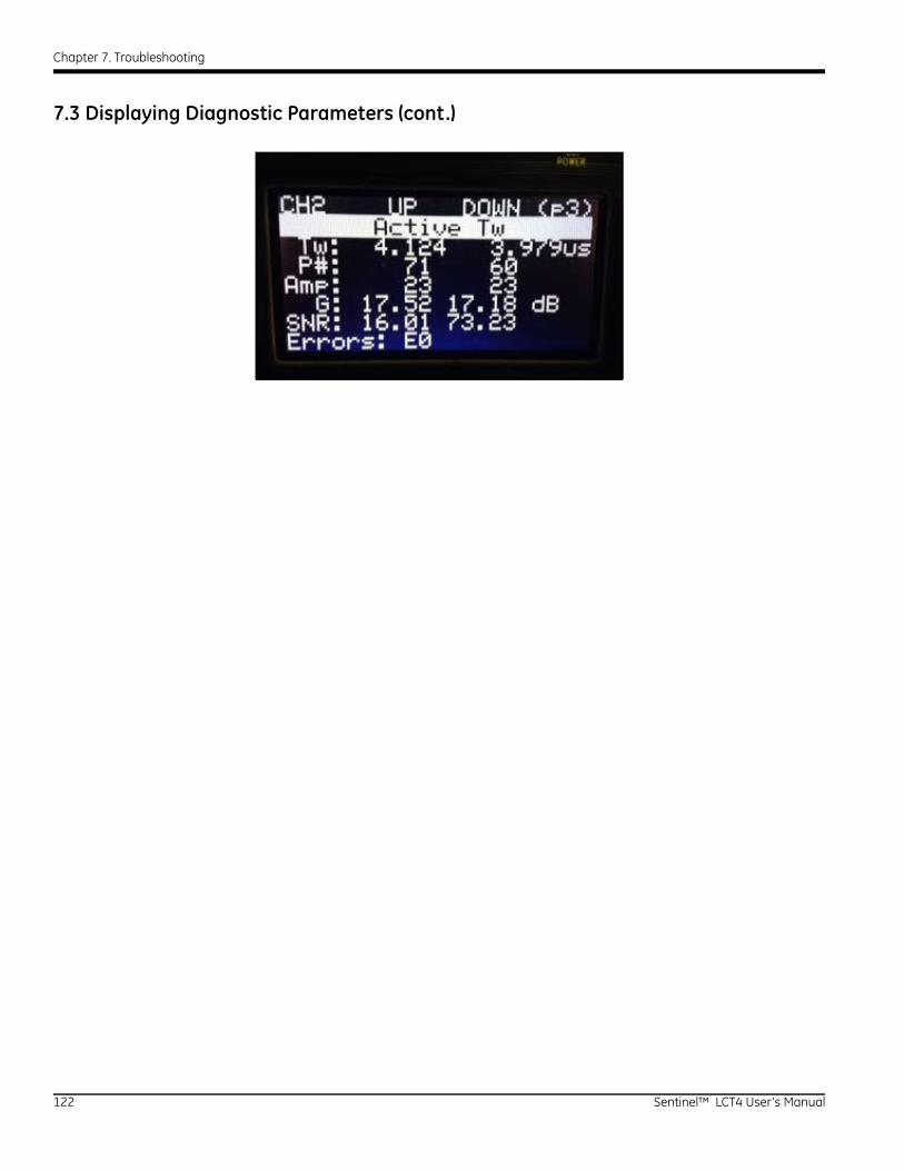
Chapter 7. Troubleshooting
7.3 Displaying Diagnostic Parameters (cont.)
122 Sentinel™ LCT4 User’s Manual
Chapter 7. Troubleshooting
7.4 Fluid and Pipe Problems
If preliminary troubleshooting with the Error Code Messages and/or the Diagnostic Parameters indicates a possible problem, proceed with this section. Measurement problems fall into two categories:
• fluid problems
• pipe problems.
Read the following sections carefully to determine if the problem is indeed related to the fluid or the pipe. If the instructions in this section fail to resolve the problem, contact the factory for assistance.
7.4.1 Fluid Problems
Most fluid-related problems result from a failure to observe the flowmeter system installation instructions, as described in Chapter 2, Installation. Refer to Chapter 2 to correct any installation problems.
If the physical installation of the system meets the recommended specifications, it is possible that the fluid itself may be preventing accurate flow rate measurements. The fluid being measured must meet the following requirements:
1. The fluid must be homogeneous, single-phase, relatively clean and flowing steadily.Although a low level of entrained particles may have little effect on the operation of the Sentinel LCT4, excessive amounts of solid particles will absorb or disperse the ultrasound signals. This interference with the ultrasound transmissions through the fluid will cause inaccurate flow rate measurements. In addition, temperature gradients in the fluid flow may result in erratic or inaccurate flow rate readings.
2. The fluid must not cavitate near the measurement point.Fluids with a high vapor pressure may cavitate near the measurement point. This causes problems resulting from gas bubbles in the fluid. Cavitation can usually be controlled through proper system design.
3. The fluid must not excessively attenuate ultrasound signals.Some fluids, particularly those that are very viscous, readily absorb ultrasound energy. In such a case, an E1 error code message will appear on the display screen to indicate that the ultrasonic signal strength is insufficient for reliable measurements.
4. The fluid soundspeed must not vary excessively.The Sentinel LCT4 will tolerate relatively large changes in the fluid soundspeed, as may be caused by variations in fluid composition and/or temperature. However, such changes must occur slowly. Rapid fluctuations in the fluid soundspeed, to a value that is considerably different from that programmed into the Sentinel LCT4, will result in erratic or inaccurate flow rate readings.
Note: Refer to Chapter 3, Operation, to make sure that the appropriate soundspeed is programmed into the meter.
Sentinel™ LCT4 User’s Manual 123
Chapter 7. Troubleshooting
7.4.2 Pipe Problems
Pipe-related problems may result from improper choice in meter location or errors in programming. The following may result in problematic installations:
1. The collection of material at the transducer location(s).Accumulated debris at the transducer location(s) will interfere with transmission of the ultrasound signals. Choose an installation point for the meter where solid particles will not settle into the transducer ports. Refer to Chapter 2, Installation, for more details on proper installation practices.
2. The inside of the pipe must be relatively clean.Excessive build up of scale, rust or debris will change the inner dimensions of the pipe and will result in inaccuracies in the calculation of the flow from the velocity measurement.
7.5 Transducer Problems
The Sentinel LCT4 transducers are rugged, reliable devices that do not come into contact with the process fluid. If erratic or inaccurate readings can be tracked to a problem with a transducer or transducers, or if one is physically damaged, the GE Measurement & Control field service team has the appropriate methods and tools to properly replace the transducer to maintain the accuracy of your flow meter system. Consult your local representative to schedule this service.
124 Sentinel™ LCT4 User’s Manual

Chapter 7. Troubleshooting
7.6 Audit Trail
The Sentinel LCT4 tracks all changes to the programming, meter status (power on, power off), error status, date/time changes, etc.
7.6.1 Audit Log
The Sentinel LCT4's Audit Log will record system activity to a human readable log and store it in persistent memory. The activity types that generate a log entry include instances of:
• Power On/Reset
• Parameter Change
• Alarms
• Error
• Calibration Change
• Default Meter
• Save/Restore/Delete Site
• Upgrade Meter
The use of additional formatting allows for better readability. The meter can store up to 1000 audit and/or event records. When the log becomes full, the new record will overwrite the oldest record in the Audit trail. This circular log will enable the user to always view the last 1000 records. The audit log file is downloadable using PanaView SEN898 software, and is not viewable from the meter’s display. It is opened as a text file and the following details are part of each record:
• Rec# - The event/record number (1-1000)
• Date - Date that the event occurred (mm/dd/yyyy)
• Time - Time that the event occurred (hh:mm:ss)
• Source- The Channel on which the event occurs. This includes the meter source, or I/O sources as well.
• ID - Corresponding Parameter ID of value that changed
• Name - Event name
• Auth. - Security level
• Old - Original Value of parameter, version, or error
• New - New value of parameter, version, or error. Also includes meter events such as alarms being tripped or power events which have no previous values.
Sentinel™ LCT4 User’s Manual 125
Chapter 7. Troubleshooting
7.6.1a Power-On/Reset
The Audit log can be used to determine the meter start or reset time. The power-on is usually the first entry in the audit log file unless it was overwritten (after 1000 entries).
7.6.1b Parameter Change
The audit log will monitor all parameters which may have an impact on the flow measurement and will record changes to them.
7.6.1c Alarms
The Audit log will record an alarm event.
7.6.1d Error
The error event will be recorded in the audit log file whenever the meter switches from a “No Error” state to “Error” state or vice versa.
7.6.1e Calibration
Any calibration change needs to be notified to the user and is hence logged in the audit log file. For example, an option card changed might affect the calibration, in which case a record will be created.
7.6.1f Default Meter
When a user defaults the meter (option enabled only for authenticated users, For Ex. Service) or a corruption that might lead to meter parameters to be defaulted occurs, an event is logged.
7.6.1g Save/Restore/Delete Site File
When a user saves, restores or deletes a site file, an event is recorded.
7.6.1h Upgrade Meter
When the meter's firmware is updated to a different version, an event is recorded.
126 Sentinel™ LCT4 User’s Manual
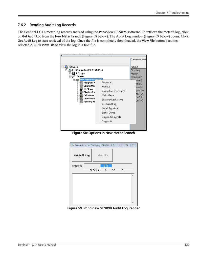
Chapter 7. Troubleshooting
7.6.2 Reading Audit Log Records
The Sentinel LCT4 meter log records are read using the PanaView SEN898 software. To retrieve the meter’s log, click on Get Audit Log from the New Meter branch (Figure 58 below). The Audit Log window (Figure 59 below) opens. Click Get Audit Log to start retrieval of the log. Once the file is completely downloaded, the View File button becomes selectable. Click View File to view the log in a text file.
Figure 58: Options in New Meter Branch
Figure 59: PanaView SEN898 Audit Log Reader
Sentinel™ LCT4 User’s Manual 127

Chapter 7. Troubleshooting
7.6.3 Formatting and Viewing Log Records
The log records have neatly formatted columns for easy and better readability. The record types mentioned in Audit Log, beginning on page 125, may contain irrelevant (not applicable) column values that are represented with ‘---’ in the corresponding column. The Audit log file contains the following columns:
For example, a parameter change will be logged in as shown below:
The Audit log file is formatted such that the user has the flexibility of viewing or saving the log file as either a Text file or a Microsoft Excel file. In order to get the full benefits of the Audit trail feature, we recommend using the Microsoft Excel file. This option, however, is available only if Microsoft® Excel® 2000 or later is installed on the PC.
Rec# Date Time Source ID Name Auth. Old New
1 12/11/2008 2:13:19 Meter --- Power --- --- Power-On
2 12/11/2008 2:13:22 --- 1 Alarm --- --- Tripped
Rec# Date Time Source ID Parameter Name Auth. Old New
1 12/11/2008 5:11:58 1 25798 RxWWidth 0 1024 2048
128 Sentinel™ LCT4 User’s Manual
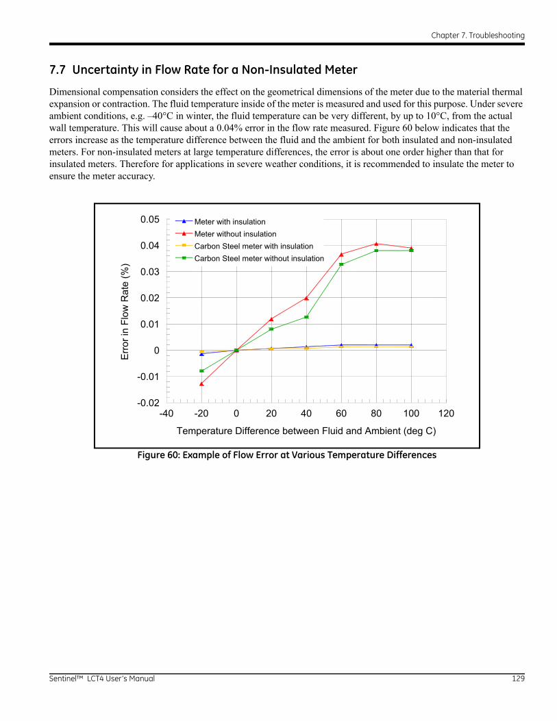
Chapter 7. Troubleshooting
7.7 Uncertainty in Flow Rate for a Non-Insulated Meter
Dimensional compensation considers the effect on the geometrical dimensions of the meter due to the material thermal expansion or contraction. The fluid temperature inside of the meter is measured and used for this purpose. Under severe ambient conditions, e.g. –40°C in winter, the fluid temperature can be very different, by up to 10°C, from the actual wall temperature. This will cause about a 0.04% error in the flow rate measured. Figure 60 below indicates that the errors increase as the temperature difference between the fluid and the ambient for both insulated and non-insulated meters. For non-insulated meters at large temperature differences, the error is about one order higher than that for insulated meters. Therefore for applications in severe weather conditions, it is recommended to insulate the meter to ensure the meter accuracy.
Figure 60: Example of Flow Error at Various Temperature Differences
Meter with insulationMeter without insulationCarbon Steel meter with insulationCarbon Steel meter without insulation
-40 -20 0 20 40 60 80 100 120-0.02
-0.01
0
0.01
0.02
0.03
0.04
0.05
Temperature Difference between Fluid and Ambient (deg C)
Err
or in
Flo
w R
ate
(%)
Sentinel™ LCT4 User’s Manual 129

Chapter 7. Troubleshooting
130 Sentinel™ LCT4 User’s Manual
Appendix A. Menu Maps
Appendix A. Menu Maps
This appendix includes the following Sentinel LCT4 procedure formats:
• Figure 61: MFG and DEV Menu Map
• Figure 62: PROG Menu Map
• Figure 63: PROG Composite Menu Map
• Figure 64: CONFIG Menu Map
• Figure 65: IO Menu Map #1
• Figure 66: IO Menu Map #2
• Figure 67: DISP, CAL, USER, and FACTORY Menu Map
Sentinel™ LCT4 User’s Manual 131

Appendix A. Menu Maps
[no content intended for this page]
132 Sentinel™ LCT4 User’s Manual

Appendix A. Menu Maps
Se 133
DEV
t Rx
y
w Info CH3 Flow Info CH4 Flow Info Flow Cal Info API Flow Info
Displays meter information.
API Option
To PROG Menu Map
User 1/2, User 3/4, User Admin Access
User 3/4, User Admin Access
User Admin Access
Figu
re 6
1: M
FG a
nd D
EV M
enu
Map
ntinel™ LCT4 User’s Manual
MFG
#
CH1 Flow Info
Watchdog Keypad Test Display Test IO Test Flow Test DAC Flow Test Tx Flow Tes
Pass: Meter restarts within 30 seconds.
Fail: Meter does NOT restart.
Keys can be tested in any order. Four different display
tests will be performed
DAC Count Tx Relay Rx Rela
CH2 Flo
Freq/Tot Test Alarm Test
Alarm #1 Alarm #2
Alarm State
Trip Reset
Freq/Tot #1 Freq/Tot #2
Frequency Totalizer
Test Freq Drive Control
Open Drain Push-Pull...Hz
Pulse Count Pulse Width Polarity Drive Control
...# ...msPositive Negative Open Drain Push-Pull
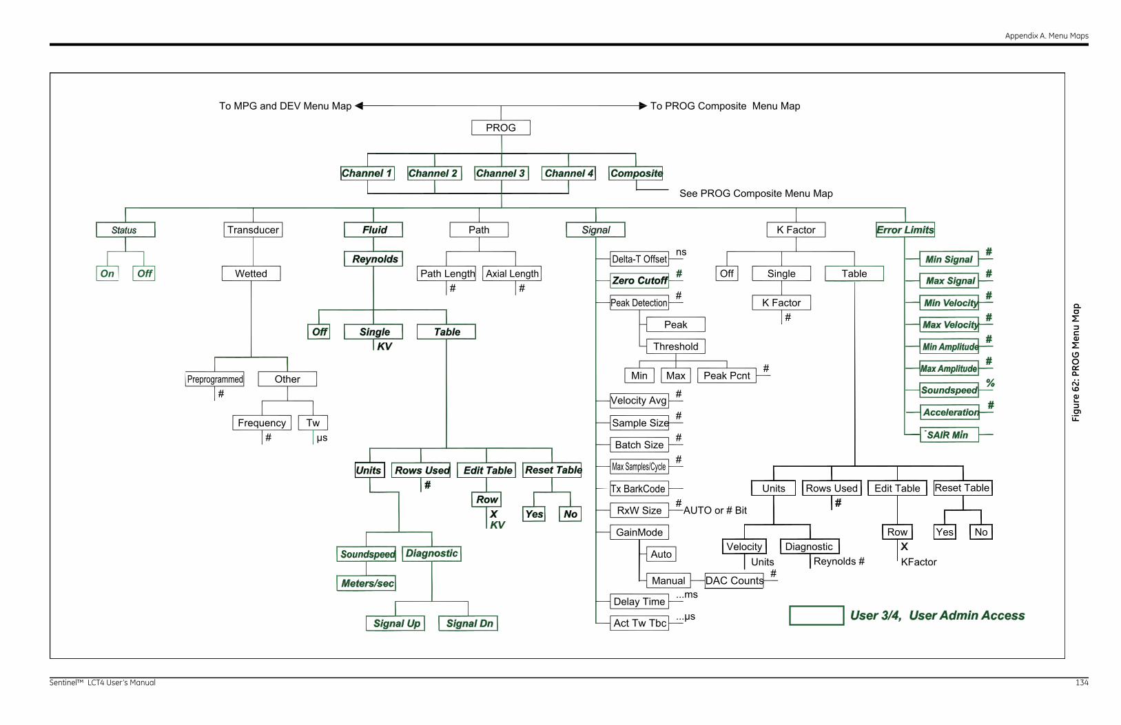
Appendix A. Menu Maps
Se 134
K Factor Error Limits
Off Single Table
See PROG Composite Menu Map
ROG Composite Menu Map
eak
eshold
ax Peak Pcnt
ual
K Factor#
ns
#
#
#
#
#
#
#
#
...ms
...μs
#
#
#
#
#
#
#
%
#
Edit Table
Diagnostic XKFactor
RowVelocity
Units Reynolds #
Rows Used#
AUTO or # Bit
NoYes
SAIR Min
Min Signal
Max Signal
Min Velocity
Max Velocity
Min Amplitude
Max Amplitude
Soundspeed
Acceleration
Units Reset Table
DAC Counts
User 3/4, User Admin Access
Figu
re 6
2: P
RO
G M
enu
Map
ntinel™ LCT4 User’s Manual
PROG
Status Transducer Fluid Path Signal
WettedOff
Other
#Frequency
Off Single Table
Edit Table
KV
Meters/sec
Signal Up Signal Dn
XKV
RowNoYes
Batch Size
Reynolds
To MPG and DEV Menu Map To P
Twμs
#
# #
P
Thr
Min M
RxW Size
GainMode
Delay Time
Auto
Man
Rows Used#
CompositeChannel 4Channel 3Channel 2Channel 1
Reset Table
Act Tw Tbc
Tx BarkCode
Max Samples/Cycle
Sample Size
Velocity Avg
DiagnosticSoundspeed
Peak Detection
Delta-T OffsetPath Length Axial Length
Preprogrammed
Zero Cutoff
Units
On

Appendix A. Menu Maps
Se 135
Density
Ratio
Reset Table
Yes No
Table
Edit Table Reset Table
RowXX Reyn #K Factor
Yes No
ChannelX
Weight
Inputs
Temperature
Fixed Active*
Fixed Active*
Fixed Active*FixedTemp #
FixedPressure #
FixedDensity #
*Menu appears only when Slot 1/2 is occupied.
API Setup
60° 20° 15°
X°
Observed
Alternate
Temp (alt)Pres (alt)
Temp (obs)Pres (obs)Dens (obs)
To CONFIG Menu Map
CHX UPCHX DN
Table A
Table C
Table B
Table D
Pressure
Base Condition Flow Measure At
User Defined
API Table Type API Conditions
Weight Factors
t Pt Filter User 3/4, User Admin Access
Figu
re 6
3: P
RO
G C
ompo
site
Men
u M
ap
ntinel™ LCT4 User’s Manual
PROG
Pipe Fluid Signal K Factor
Composite
Material Lining
Other
Pipe Size
OD #WT #ODxPI #
Schedule**
OD #WT #ODxPI #
Material
Other
Thickness #
Fluid Type
Normal Tracking
OtherTemperature
Fluid TypeSndspd #
OtherMin Sndspd #Max Sndspd #
TxVoltage
Zero Interp
K Factor Path
SingleOff TableValue
Edit TableUnits
Velocity
RowXX Reyn #K Factor #
Off
**Appears only if one of the following materials is selected:Carbon Steel (all)Stainless (all)Iron CastIron DuctilePlastic PVCPlastic CPVC
To PROG Menu Map
Path Ratio Alpha #Path Ratio Min #Path Ratio Max #
Yes or No
AUTO, Off or On
Spline or SincDiagnostic
Rows Used#
Reynolds#Active Tw StatusActive Tw Temp Change #Active Tw Interval #Active Tw Cycles #Peak Pcnt %
X Point CorrelationOptimized Correlation
Rows Used#
Velocity Alpha
Velocity Interp
Atten Enable
Correlation Type TesPreprogrammed Preprogrammed
Preprogrammed
PreprogrammedSoundspeed #
Material Type Path Ratio Menu
Soundspeed #Material Type
Soundspeed #
AUTO, High or Low
Gain Hysteresis
Meters/secActive Tw Config
On or Off
Compensation Status
Channel 1 Channel 2 Channel 3 Channel 4
Error Allowed
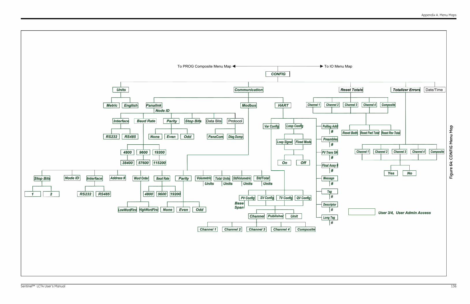
Appendix A. Menu Maps
Se 136
Reset Totals Totalizer Errors
ART
Unit
OffOn
#
#
#
#
#
#
#
#
NoYes
To IO Menu Map
Compositenel 4
er
V Config QV Config
Final Assy #
Loop Config
op Signal Fixed Mode
PV Trans SN
Preambles
Polling Addr
CompositeChannel 4Channel 3Channel 2Channel 1
CompositeChannel 4Channel 3Channel 2Channel 1
Reset Both Reset Fwd Total Reset Rev Total
Date/Time
User 3/4, User Admin Access
Message
Tag
Descriptor
Long Tag
IG
Figu
re 6
4: C
ON
FIG
Men
u M
ap
ntinel™ LCT4 User’s Manual
Units
Metric English Modbus H
Interface Parity
RS232 RS485 4800 192009600
None OddEven
Panalink
Interface Parity
Units Units Units Units
RS232 RS485
4800 192009600
38400 11520057600
Even Odd
Baud Rate
Node ID
Stop Bits Data Bits Protocol
Channel
BaseSpan
To PROG Composite Menu Map
Stop Bits
1 2
Word Order Baud Rate Volumetric StdVolumetricTotal Units
LowWordFirst HighWordFirst
StdTotal
PV Config
ChanChannel 3Channel 2Channel 1
Publish
SV Config T
Var Config
LoPanaCom Diag DumpNone
Communication
CONF
Node ID Address #
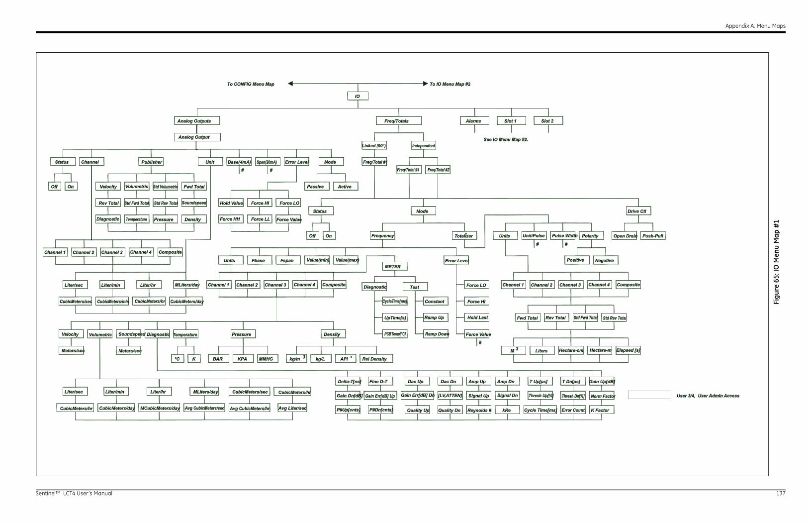
Appendix A. Menu Maps
Se 137
Drive Ctl
p Amp Dn T Up[μs] T Dn[μs]
kRe K Factor
Units Polarity
M Liters3
# #
Slot 1 Slot 2
See IO Menu Map #2.
Unit/Pulse Pulse Width Open Drain Push-Pull
Channel 2Channel 1 Channel 3 Channel 4 Composite
Fwd Total Rev Total Std Fwd Total Std Rev Total
Hectare-cm Hectare-m Elapsed [s]
st
O
I
lue
Up Signal Dn
Gain Up[dB]
Thresh Up[%] Thresh Dn[%] Norm Factor
Error Countds # Cycle Time[ms]
Positive Negative
User 3/4, User Admin Access
Figu
re 6
5: IO
Men
u M
ap #
1
ntinel™ LCT4 User’s Manual
Analog Outputs
IO
Status Unit Mode
OnOff
Channel
Pressure Density
Liter/hrLiter/minLiter/sec
Passive Active
# #
Freq/Totals
Status Mode
OnOff
FspanFbaseMETER
Pressure Density
Liter/hrLiter/minLiter/sec
Fine D-T Dac Up Dac Dn Amp U
K°C MMHGBAR KPA API kg/m kg/L3
#
Test
Alarms
Units
To CONFIG Menu Map To IO Menu Map #2
Analog Output
Channel 2Channel 1 Channel 3 Channel 4 Composite
Channel 2Channel 1 Channel 3 Channel 4 CompositeMLiters/day
CubicMeters/sec CubicMeters/min CubicMeters/hr CubicMeters/day
CubicMeters/hr CubicMeters/day MCubicMeters/day Avg CubicMeters/sec
Velocity
MLiters/day CubicMeters/sec CubicMeters/hr
Avg CubicMeters/hr Avg Liter/sec
Meters/sec Meters/sec
Volumetric Soundspeed Diagnostic Temperature
Diagnostic
Frequency Totalizer
Error Level
Hold La
Force L
Force H
Force Va
CycleTime[ms]
UpTime[s]
PCBTemp[°C]
Constant
Ramp Up
Ramp Down
Value(min) Value(max)
Velocity Volumetric
Soundspeed
Diagnostic Temperature
Std Volumetric Fwd Total
Std Fwd TotalRev Total Std Rev Total
Publisher Base(4mA) Span(20mA) Error Level
Hold Value
Force Value
Force LOForce HI
Force LLForce HH
Linked (90°)
Freq/Total #1Freq/Total #1 Freq/Total #2
Independent
Rel Density
Gain Dn[dB] Gain Err[dB] Up Gain Err[dB] Dn [LV,ATTEN] Signal
P#Up[cnts] P#Dn[cnts] Quality Up Quality Dn Reynol
Delta-T[ns]

Appendix A. Menu Maps
Se 138
Slot 1 Slot 2 Note: Menu appears only when Slot is occupied.
#A:Ain #B:Ain #C:Ain
Label Mode Cal#
Off Temp Yes No
Set Pt1Offset 1
Set Pt5Offset 5
Mode Cal
Yes NoYes No Yes No
Density
ase Span# #
To DISP, CAL, USER, FACTORY Menu Map
Base TrimSpan TrimTrim BaseTrim SpanReset Trim
Reset Table
Reset Table
#C: Temp(RTD)
sure
User 3/4, User Admin Access
Note: #C depends on type of option card selected.
Reset Table Reset Table
Figu
re 6
6: IO
Men
u M
ap #
2
ntinel™ LCT4 User’s Manual
IO
Alarms
Alarm #1 Alarm #2
Status TYPE
Off Normal Level Fault
# #
Reset Trip
*See "Units" inIO Menu Map #1
(on previous page)to observe options.
Flow All
*See "Units" inIO Menu Map #1
(on previous page)to observe options.
**Refer to the table below.
Latch No Latch
Yes No
Label#
TempOff
Units B#
To Analog Outputs and Freq/Totals
To IO Menu Map #1
Units* Units* Units*Trip Point
Trip Above Trip Below
Trip Direction
Hold Last
Dead Band Error Level
Direction
Custom**
Clear Latch
Latch State
Non-Flow
PresFault State of Alarm
E1 Low Signal E17 Temperature Input E2 Soundspeed E18 Pressure Input E3 Vel/Range E19 Density Input E4 Signal Quality E20 Spec Input E5 Amplitude E21 API Error E6 Accelera on E22 Degraded Performance E7 Aout Range E23 Reduced Accuracy E13 Tracking AGC E24 SNR E14 Tracking Seek E29 Stale Data E15 Ac ve Tw E30 Channel O E16 Total Over ow
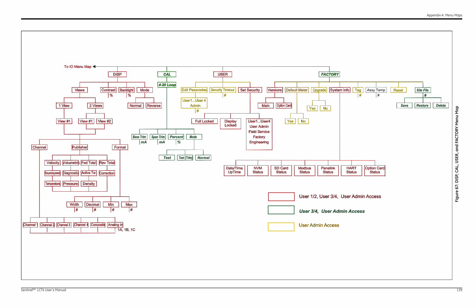
Appendix A. Menu Maps
Se 139
UpgradeDefault Meter TagSystem Info
Yes No
Assy Temp# #
rds
ModbusStatus
PanalinkStatus
HARTStatus
Option CardStatus
Save Restore DeleteYes No
User Admin AccessC
Card
User 3/4, User Admin Access
User 1/2, User 3/4, User Admin Access
#Site FileReset
FACTORY
Figu
re 6
7: D
ISP,
CA
L, U
SER
, and
FA
CTO
RY M
enu
Map
ntinel™ LCT4 User’s Manual
DISP
FormatChannel
Density
MinDecimalWidth
Views Contrast Mode
1 View 2 Views
View #1 View #2View #1
% %
Normal Reverse
Pressure
Max# # # #
CAL
ModemA %
Normal
PercentmA
Test
4-20 Loop
USER
Display
Set Security#
Admin#
Full LockedLocked
User1...User4User Admin
Field ServiceFactory
Engineering
Versions
Main
Date/TimeUpTime
NVMStatus
SD CaStatu
To IO Menu Map
1A, 1B, 1CChannel 2hannel 1 Channel 3 Channel 4 Composite Analog in
Active Tw Correction
Velocity Volumetric
Soundspeed Diagnostic
Temperature
Fwd Total
Publisher
Rev Total
Backlight
Span Trim
Test [Trim]
Edit Passcodes Security Timeout
Option
Base Trim

Appendix A. Menu Maps
Se 140
ntinel™ LCT4 User’s Manual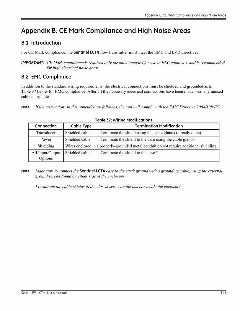
Appendix B. CE Mark Compliance and High Noise Areas
Appendix B. CE Mark Compliance and High Noise Areas
B.1 Introduction
For CE Mark compliance, the Sentinel LCT4 flow transmitter must meet the EMC and LVD directives.
IMPORTANT: CE Mark compliance is required only for units intended for use in EEC countries, and is recommended for high electrical noise areas.
B.2 EMC Compliance
In addition to the standard wiring requirements, the electrical connections must be shielded and grounded as in Table 37 below for EMC compliance. After all the necessary electrical connections have been made, seal any unused cable entry holes.
Note: If the instructions in this appendix are followed, the unit will comply with the EMC Directive 2004/108/EC.
Note: Make sure to connect the Sentinel LCT4 case to the earth ground with a grounding cable, using the external ground screws found on either side of the enclosure
*Terminate the cable shields to the closest screw on the bus bar inside the enclosure.
Table 37: Wiring ModificationsConnection Cable Type Termination Modification
Transducer Shielded cable Terminate the shield using the cable glands (already done).
Power Shielded cable Terminate the shield to the case using the cable glands.
Shielding Wires enclosed in a properly-grounded metal conduit do not require additional shielding.
All Input/Output Options
Shielded cable Terminate the shield to the case.*
Sentinel™ LCT4 User’s Manual 141

Appendix B. CE Mark Compliance and High Noise Areas
[no content intended for this page]
142 Sentinel™ LCT4 User’s Manual
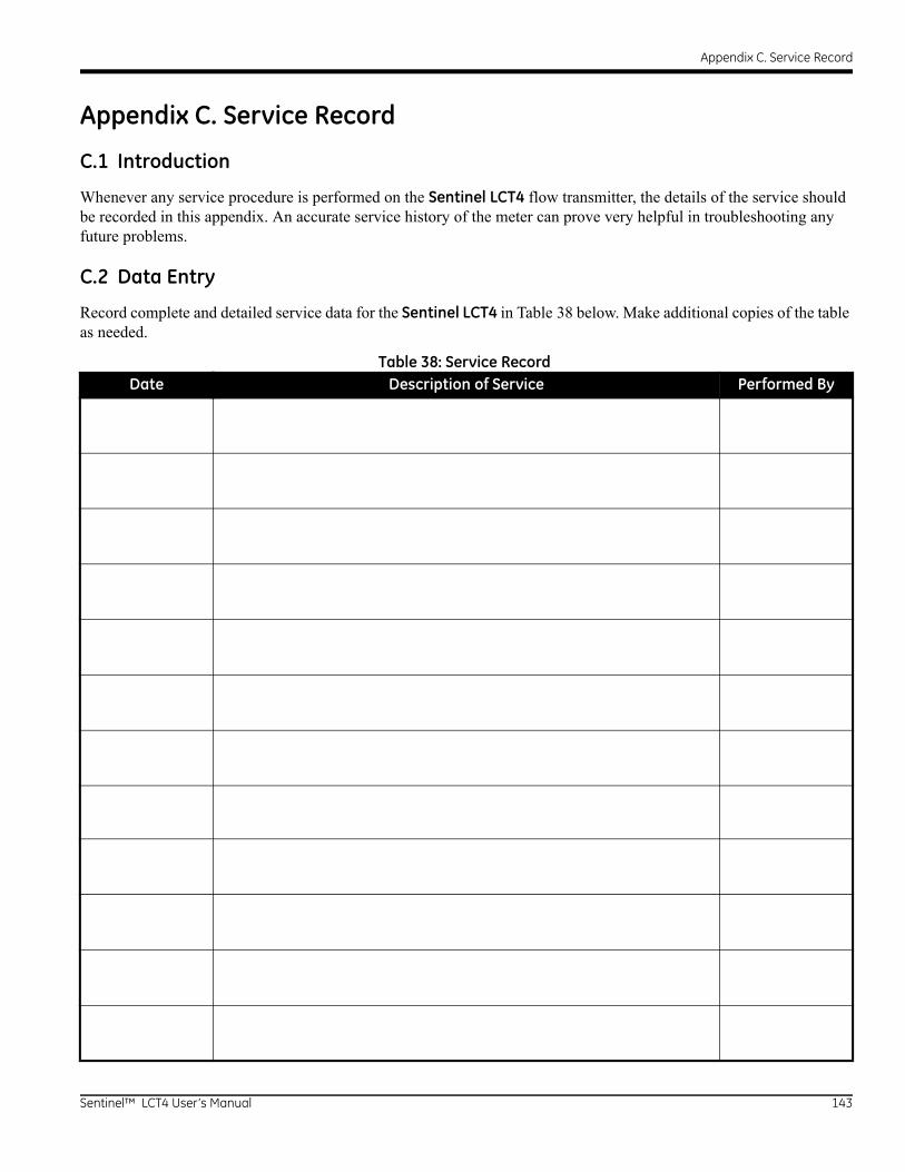
Appendix C. Service Record
Appendix C. Service Record
C.1 Introduction
Whenever any service procedure is performed on the Sentinel LCT4 flow transmitter, the details of the service should be recorded in this appendix. An accurate service history of the meter can prove very helpful in troubleshooting any future problems.
C.2 Data Entry
Record complete and detailed service data for the Sentinel LCT4 in Table 38 below. Make additional copies of the table as needed.
Table 38: Service RecordDate Description of Service Performed By
Sentinel™ LCT4 User’s Manual 143

Appendix C. Service Record
Table 38: Service Record (cont.)Date Description of Service Performed By
144 Sentinel™ LCT4 User’s Manual
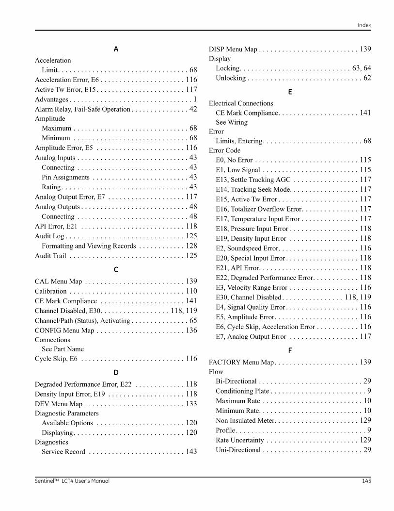
Index
AAcceleration
Limit. . . . . . . . . . . . . . . . . . . . . . . . . . . . . . . . . . 68Acceleration Error, E6 . . . . . . . . . . . . . . . . . . . . . . 116Active Tw Error, E15 . . . . . . . . . . . . . . . . . . . . . . . 117Advantages . . . . . . . . . . . . . . . . . . . . . . . . . . . . . . . . 1Alarm Relay, Fail-Safe Operation . . . . . . . . . . . . . . . 42Amplitude
Maximum . . . . . . . . . . . . . . . . . . . . . . . . . . . . . . 68Minimum . . . . . . . . . . . . . . . . . . . . . . . . . . . . . . 68
Amplitude Error, E5 . . . . . . . . . . . . . . . . . . . . . . . 116Analog Inputs . . . . . . . . . . . . . . . . . . . . . . . . . . . . . 43
Connecting . . . . . . . . . . . . . . . . . . . . . . . . . . . . . 43Pin Assignments . . . . . . . . . . . . . . . . . . . . . . . . . 43Rating . . . . . . . . . . . . . . . . . . . . . . . . . . . . . . . . . 43
Analog Output Error, E7 . . . . . . . . . . . . . . . . . . . . 117Analog Outputs . . . . . . . . . . . . . . . . . . . . . . . . . . . . 48
Connecting . . . . . . . . . . . . . . . . . . . . . . . . . . . . . 48API Error, E21 . . . . . . . . . . . . . . . . . . . . . . . . . . . 118Audit Log . . . . . . . . . . . . . . . . . . . . . . . . . . . . . . . 125
Formatting and Viewing Records . . . . . . . . . . . . 128Audit Trail . . . . . . . . . . . . . . . . . . . . . . . . . . . . . . 125
C
CAL Menu Map . . . . . . . . . . . . . . . . . . . . . . . . . . 139Calibration . . . . . . . . . . . . . . . . . . . . . . . . . . . . . . 110CE Mark Compliance . . . . . . . . . . . . . . . . . . . . . . 141Channel Disabled, E30. . . . . . . . . . . . . . . . . . 118, 119Channel/Path (Status), Activating . . . . . . . . . . . . . . . 65CONFIG Menu Map . . . . . . . . . . . . . . . . . . . . . . . 136Connections
See Part NameCycle Skip, E6 . . . . . . . . . . . . . . . . . . . . . . . . . . . 116
D
Degraded Performance Error, E22 . . . . . . . . . . . . . 118Density Input Error, E19 . . . . . . . . . . . . . . . . . . . . 118DEV Menu Map . . . . . . . . . . . . . . . . . . . . . . . . . . 133Diagnostic Parameters
Available Options . . . . . . . . . . . . . . . . . . . . . . . 120Displaying. . . . . . . . . . . . . . . . . . . . . . . . . . . . . 120
DiagnosticsService Record . . . . . . . . . . . . . . . . . . . . . . . . . 143
DISP Menu Map . . . . . . . . . . . . . . . . . . . . . . . . . . 139Display
Locking. . . . . . . . . . . . . . . . . . . . . . . . . . . . . 63, 64Unlocking . . . . . . . . . . . . . . . . . . . . . . . . . . . . . . 62
EElectrical Connections
CE Mark Compliance. . . . . . . . . . . . . . . . . . . . . 141See Wiring
ErrorLimits, Entering. . . . . . . . . . . . . . . . . . . . . . . . . . 68
Error CodeE0, No Error . . . . . . . . . . . . . . . . . . . . . . . . . . . 115E1, Low Signal . . . . . . . . . . . . . . . . . . . . . . . . . 115E13, Settle Tracking AGC . . . . . . . . . . . . . . . . . 117E14, Tracking Seek Mode. . . . . . . . . . . . . . . . . . 117E15, Active Tw Error . . . . . . . . . . . . . . . . . . . . . 117E16, Totalizer Overflow Error. . . . . . . . . . . . . . . 117E17, Temperature Input Error . . . . . . . . . . . . . . . 117E18, Pressure Input Error . . . . . . . . . . . . . . . . . . 118E19, Density Input Error . . . . . . . . . . . . . . . . . . 118E2, Soundspeed Error. . . . . . . . . . . . . . . . . . . . . 116E20, Special Input Error . . . . . . . . . . . . . . . . . . . 118E21, API Error. . . . . . . . . . . . . . . . . . . . . . . . . . 118E22, Degraded Performance Error. . . . . . . . . . . . 118E3, Velocity Range Error . . . . . . . . . . . . . . . . . . 116E30, Channel Disabled . . . . . . . . . . . . . . . . 118, 119E4, Signal Quality Error . . . . . . . . . . . . . . . . . . . 116E5, Amplitude Error. . . . . . . . . . . . . . . . . . . . . . 116E6, Cycle Skip, Acceleration Error . . . . . . . . . . . 116E7, Analog Output Error . . . . . . . . . . . . . . . . . . 117
F
FACTORY Menu Map. . . . . . . . . . . . . . . . . . . . . . 139Flow
Bi-Directional . . . . . . . . . . . . . . . . . . . . . . . . . . . 29Conditioning Plate . . . . . . . . . . . . . . . . . . . . . . . . . 9Maximum Rate . . . . . . . . . . . . . . . . . . . . . . . . . . 10Minimum Rate. . . . . . . . . . . . . . . . . . . . . . . . . . . 10Non Insulated Meter. . . . . . . . . . . . . . . . . . . . . . 129Profile . . . . . . . . . . . . . . . . . . . . . . . . . . . . . . . . . . 9Rate Uncertainty . . . . . . . . . . . . . . . . . . . . . . . . 129Uni-Directional . . . . . . . . . . . . . . . . . . . . . . . . . . 29
Sentinel™ LCT4 User’s Manual 145
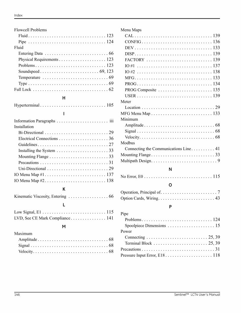
Index
Flowcell ProblemsFluid . . . . . . . . . . . . . . . . . . . . . . . . . . . . . . . . . 123Pipe . . . . . . . . . . . . . . . . . . . . . . . . . . . . . . . . . 124
FluidEntering Data . . . . . . . . . . . . . . . . . . . . . . . . . . . 66Physical Requirements . . . . . . . . . . . . . . . . . . . . 123Problems . . . . . . . . . . . . . . . . . . . . . . . . . . . . . . 123Soundspeed . . . . . . . . . . . . . . . . . . . . . . . . . 69, 123Temperature . . . . . . . . . . . . . . . . . . . . . . . . . . . . 69Type . . . . . . . . . . . . . . . . . . . . . . . . . . . . . . . . . . 69
Full Lock . . . . . . . . . . . . . . . . . . . . . . . . . . . . . . . . 62
H
Hyperterminal . . . . . . . . . . . . . . . . . . . . . . . . . . . . 105
I
Information Paragraphs . . . . . . . . . . . . . . . . . . . . . . iiiInstallation
Bi-Directional . . . . . . . . . . . . . . . . . . . . . . . . . . . 29Electrical Connections . . . . . . . . . . . . . . . . . . . . . 36Guidelines . . . . . . . . . . . . . . . . . . . . . . . . . . . . . . 27Installing the System . . . . . . . . . . . . . . . . . . . . . . 33Mounting Flange . . . . . . . . . . . . . . . . . . . . . . . . . 33Precautions . . . . . . . . . . . . . . . . . . . . . . . . . . . . . 31Uni-Directional . . . . . . . . . . . . . . . . . . . . . . . . . . 29
IO Menu Map #1 . . . . . . . . . . . . . . . . . . . . . . . . . . 137IO Menu Map #2 . . . . . . . . . . . . . . . . . . . . . . . . . . 138
K
Kinematic Viscosity, Entering . . . . . . . . . . . . . . . . . 66
L
Low Signal, E1 . . . . . . . . . . . . . . . . . . . . . . . . . . . 115LVD, See CE Mark Compliance . . . . . . . . . . . . . . . 141
MMaximum
Amplitude . . . . . . . . . . . . . . . . . . . . . . . . . . . . . . 68Signal . . . . . . . . . . . . . . . . . . . . . . . . . . . . . . . . . 68Velocity. . . . . . . . . . . . . . . . . . . . . . . . . . . . . . . . 68
Menu MapsCAL . . . . . . . . . . . . . . . . . . . . . . . . . . . . . . . . . 139CONFIG . . . . . . . . . . . . . . . . . . . . . . . . . . . . . . 136DEV . . . . . . . . . . . . . . . . . . . . . . . . . . . . . . . . . 133DISP. . . . . . . . . . . . . . . . . . . . . . . . . . . . . . . . . 139FACTORY . . . . . . . . . . . . . . . . . . . . . . . . . . . . 139IO #1 . . . . . . . . . . . . . . . . . . . . . . . . . . . . . . . . 137IO #2 . . . . . . . . . . . . . . . . . . . . . . . . . . . . . . . . 138MFG. . . . . . . . . . . . . . . . . . . . . . . . . . . . . . . . . 133PROG . . . . . . . . . . . . . . . . . . . . . . . . . . . . . . . . 134PROG Composite . . . . . . . . . . . . . . . . . . . . . . . 135USER . . . . . . . . . . . . . . . . . . . . . . . . . . . . . . . . 139
MeterLocation . . . . . . . . . . . . . . . . . . . . . . . . . . . . . . . 29
MFG Menu Map . . . . . . . . . . . . . . . . . . . . . . . . . . 133Minimum
Amplitude . . . . . . . . . . . . . . . . . . . . . . . . . . . . . . 68Signal . . . . . . . . . . . . . . . . . . . . . . . . . . . . . . . . . 68Velocity. . . . . . . . . . . . . . . . . . . . . . . . . . . . . . . . 68
ModbusConnecting the Communications Line . . . . . . . . . . 41
Mounting Flange . . . . . . . . . . . . . . . . . . . . . . . . . . . 33Multipath Design. . . . . . . . . . . . . . . . . . . . . . . . . . . . 9
N
No Error, E0 . . . . . . . . . . . . . . . . . . . . . . . . . . . . . 115
O
Operation, Principal of. . . . . . . . . . . . . . . . . . . . . . . . 7Option Cards, Wiring. . . . . . . . . . . . . . . . . . . . . . . . 43
PPipe
Problems . . . . . . . . . . . . . . . . . . . . . . . . . . . . . . 124Spoolpiece Dimensions . . . . . . . . . . . . . . . . . . . . 15
PowerConnecting . . . . . . . . . . . . . . . . . . . . . . . . . . 25, 39Terminal Block . . . . . . . . . . . . . . . . . . . . . . . 25, 39
Precautions . . . . . . . . . . . . . . . . . . . . . . . . . . . . . . . 31Pressure Input Error, E18 . . . . . . . . . . . . . . . . . . . . 118
146 Sentinel™ LCT4 User’s Manual
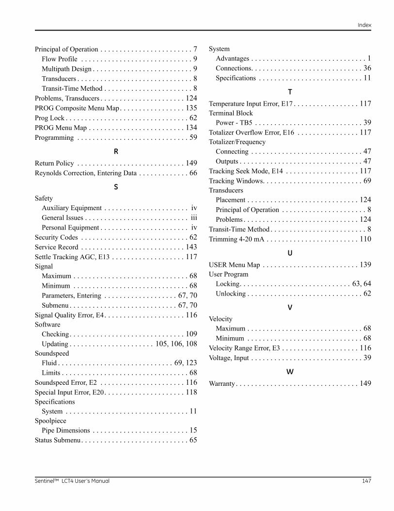
Index
Principal of Operation . . . . . . . . . . . . . . . . . . . . . . . . 7Flow Profile . . . . . . . . . . . . . . . . . . . . . . . . . . . . . 9Multipath Design . . . . . . . . . . . . . . . . . . . . . . . . . . 9Transducers . . . . . . . . . . . . . . . . . . . . . . . . . . . . . . 8Transit-Time Method . . . . . . . . . . . . . . . . . . . . . . . 8
Problems, Transducers . . . . . . . . . . . . . . . . . . . . . . 124PROG Composite Menu Map. . . . . . . . . . . . . . . . . 135Prog Lock . . . . . . . . . . . . . . . . . . . . . . . . . . . . . . . . 62PROG Menu Map . . . . . . . . . . . . . . . . . . . . . . . . . 134Programming . . . . . . . . . . . . . . . . . . . . . . . . . . . . . 59
R
Return Policy . . . . . . . . . . . . . . . . . . . . . . . . . . . . 149Reynolds Correction, Entering Data . . . . . . . . . . . . . 66
SSafety
Auxiliary Equipment . . . . . . . . . . . . . . . . . . . . . . ivGeneral Issues . . . . . . . . . . . . . . . . . . . . . . . . . . . iiiPersonal Equipment . . . . . . . . . . . . . . . . . . . . . . . iv
Security Codes . . . . . . . . . . . . . . . . . . . . . . . . . . . . 62Service Record . . . . . . . . . . . . . . . . . . . . . . . . . . . 143Settle Tracking AGC, E13 . . . . . . . . . . . . . . . . . . . 117Signal
Maximum . . . . . . . . . . . . . . . . . . . . . . . . . . . . . . 68Minimum . . . . . . . . . . . . . . . . . . . . . . . . . . . . . . 68Parameters, Entering . . . . . . . . . . . . . . . . . . . 67, 70Submenu . . . . . . . . . . . . . . . . . . . . . . . . . . . . 67, 70
Signal Quality Error, E4. . . . . . . . . . . . . . . . . . . . . 116Software
Checking. . . . . . . . . . . . . . . . . . . . . . . . . . . . . . 109Updating . . . . . . . . . . . . . . . . . . . . . . 105, 106, 108
SoundspeedFluid . . . . . . . . . . . . . . . . . . . . . . . . . . . . . . 69, 123Limits . . . . . . . . . . . . . . . . . . . . . . . . . . . . . . . . . 68
Soundspeed Error, E2 . . . . . . . . . . . . . . . . . . . . . . 116Special Input Error, E20. . . . . . . . . . . . . . . . . . . . . 118Specifications
System . . . . . . . . . . . . . . . . . . . . . . . . . . . . . . . . 11Spoolpiece
Pipe Dimensions . . . . . . . . . . . . . . . . . . . . . . . . . 15Status Submenu. . . . . . . . . . . . . . . . . . . . . . . . . . . . 65
SystemAdvantages . . . . . . . . . . . . . . . . . . . . . . . . . . . . . . 1Connections. . . . . . . . . . . . . . . . . . . . . . . . . . . . . 36Specifications . . . . . . . . . . . . . . . . . . . . . . . . . . . 11
T
Temperature Input Error, E17 . . . . . . . . . . . . . . . . . 117Terminal Block
Power - TB5 . . . . . . . . . . . . . . . . . . . . . . . . . . . . 39Totalizer Overflow Error, E16 . . . . . . . . . . . . . . . . 117Totalizer/Frequency
Connecting . . . . . . . . . . . . . . . . . . . . . . . . . . . . . 47Outputs . . . . . . . . . . . . . . . . . . . . . . . . . . . . . . . . 47
Tracking Seek Mode, E14 . . . . . . . . . . . . . . . . . . . 117Tracking Windows. . . . . . . . . . . . . . . . . . . . . . . . . . 69Transducers
Placement . . . . . . . . . . . . . . . . . . . . . . . . . . . . . 124Principal of Operation . . . . . . . . . . . . . . . . . . . . . . 8Problems . . . . . . . . . . . . . . . . . . . . . . . . . . . . . . 124
Transit-Time Method . . . . . . . . . . . . . . . . . . . . . . . . . 8Trimming 4-20 mA . . . . . . . . . . . . . . . . . . . . . . . . 110
U
USER Menu Map . . . . . . . . . . . . . . . . . . . . . . . . . 139User Program
Locking. . . . . . . . . . . . . . . . . . . . . . . . . . . . . 63, 64Unlocking . . . . . . . . . . . . . . . . . . . . . . . . . . . . . . 62
VVelocity
Maximum . . . . . . . . . . . . . . . . . . . . . . . . . . . . . . 68Minimum . . . . . . . . . . . . . . . . . . . . . . . . . . . . . . 68
Velocity Range Error, E3 . . . . . . . . . . . . . . . . . . . . 116Voltage, Input . . . . . . . . . . . . . . . . . . . . . . . . . . . . . 39
W
Warranty . . . . . . . . . . . . . . . . . . . . . . . . . . . . . . . . 149
Sentinel™ LCT4 User’s Manual 147
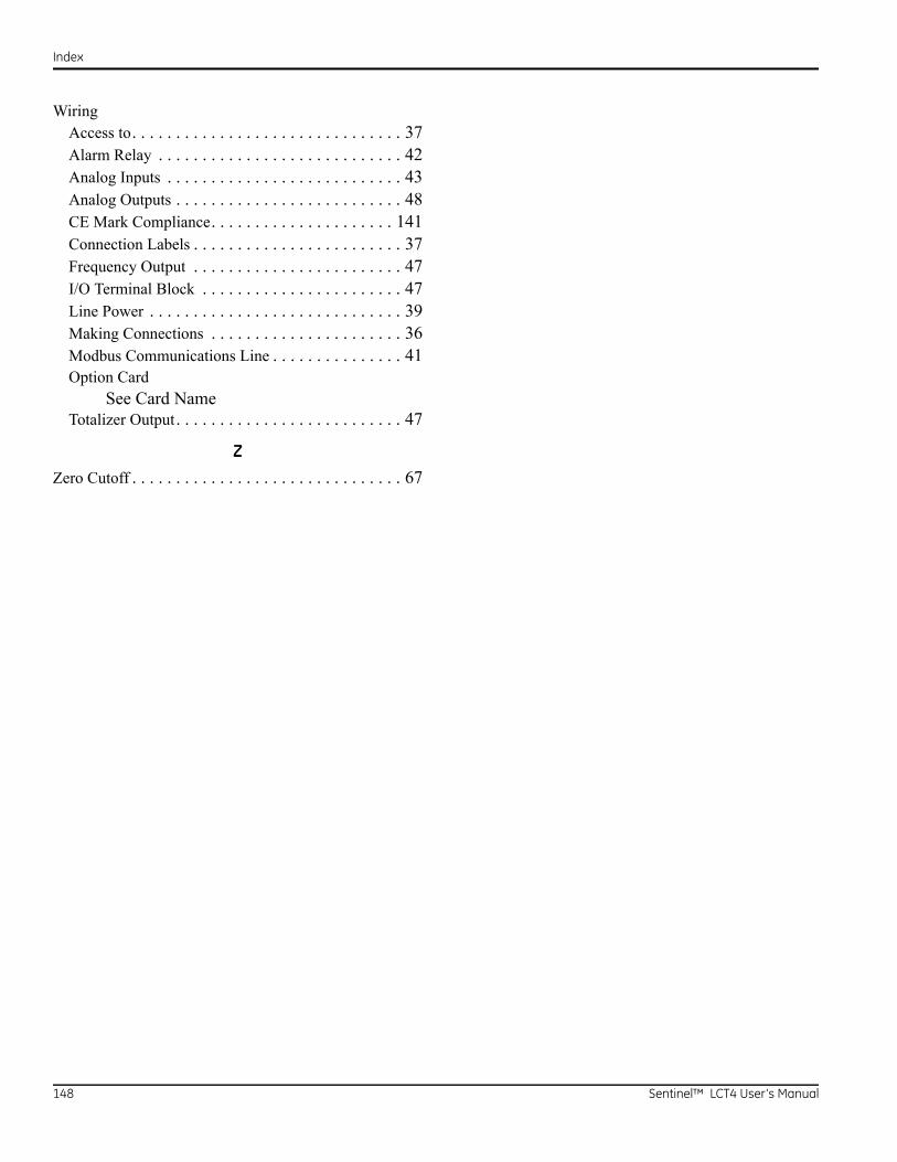
Index
WiringAccess to. . . . . . . . . . . . . . . . . . . . . . . . . . . . . . . 37Alarm Relay . . . . . . . . . . . . . . . . . . . . . . . . . . . . 42Analog Inputs . . . . . . . . . . . . . . . . . . . . . . . . . . . 43Analog Outputs . . . . . . . . . . . . . . . . . . . . . . . . . . 48CE Mark Compliance. . . . . . . . . . . . . . . . . . . . . 141Connection Labels . . . . . . . . . . . . . . . . . . . . . . . . 37Frequency Output . . . . . . . . . . . . . . . . . . . . . . . . 47I/O Terminal Block . . . . . . . . . . . . . . . . . . . . . . . 47Line Power . . . . . . . . . . . . . . . . . . . . . . . . . . . . . 39Making Connections . . . . . . . . . . . . . . . . . . . . . . 36Modbus Communications Line . . . . . . . . . . . . . . . 41Option Card
See Card NameTotalizer Output. . . . . . . . . . . . . . . . . . . . . . . . . . 47
Z
Zero Cutoff . . . . . . . . . . . . . . . . . . . . . . . . . . . . . . . 67
148 Sentinel™ LCT4 User’s Manual
Warranty
Warranty
Each instrument manufactured by GE Sensing is warranted to be free from defects in material and workmanship. Liability under this warranty is limited to restoring the instrument to normal operation or replacing the instrument, at the sole discretion of GE Sensing. Fuses and batteries are specifically excluded from any liability. This warranty is effective from the date of delivery to the original purchaser. If GE Sensing determines that the equipment was defective, the warranty period is:
• one year from delivery for electronic or mechanical failures
• one year from delivery for sensor shelf life
If GE Sensing determines that the equipment was damaged by misuse, improper installation, the use of unauthorized replacement parts, or operating conditions outside the guidelines specified by GE Sensing, the repairs are not covered under this warranty.
The warranties set forth herein are exclusive and are in lieu of all other warranties whether statutory, express or implied (including warranties or merchantability and fitness for a particular purpose, and warranties arising from course of dealing or usage or trade).
Return Policy
If a GE Sensing instrument malfunctions within the warranty period, the following procedure must be completed:
1. Notify GE Sensing, giving full details of the problem, and provide the model number and serial number of the instrument. If the nature of the problem indicates the need for factory service, GE Sensing will issue a RETURN AUTHORIZATION NUMBER (RAN), and shipping instructions for the return of the instrument to a service center will be provided.
2. If GE Sensing instructs you to send your instrument to a service center, it must be shipped prepaid to the authorized repair station indicated in the shipping instructions.
3. Upon receipt, GE Sensing will evaluate the instrument to determine the cause of the malfunction.
Then, one of the following courses of action will then be taken:
• If the damage is covered under the terms of the warranty, the instrument will be repaired at no cost to the owner and returned.
• If GE Sensing determines that the damage is not covered under the terms of the warranty, or if the warranty has expired, an estimate for the cost of the repairs at standard rates will be provided. Upon receipt of the owner’s approval to proceed, the instrument will be repaired and returned.
Sentinel™ LCT4 User’s Manual 149

Warranty
[no content intended for this page]
150 Sentinel™ LCT4 User’s Manual

GEMeasurement & Control
Certification &Safety Statements
Certification & Safety Statements for the Sentinel™ LCT4
When installing this apparatus, the following requirements must be met:
• Field wiring shall be rated at least 10°C above 85°C.
• Connecting cables shall be mounted securely and protected from mechanical damage, pulling and twisting.
• Cable entries are ¾” NPT.
• Cable glands of an approved flameproof design are required. These must be installed according to the manufacturer's instructions. Where the cable glands are provided by GE, the manufacturer's instructions, as supplied, to GE, will be included in the documentation.
• The system is covered by the certificate numbers FM13ATEX0018X and IECEx FMG 13.0008X as shown on the labels on the following page. The system is certified as Ex d e IIB +H2 T6…T140°C Gb in -40° to +60°C ambient. The system temperature code is dependent upon the process fluid temperature range of -40°C to 140°C. The surface temperature of the sensor body and electronics can approach the process fluid temperatures and all necessary precautions should be taken. Remote mounting of the electronics is required for process temperatures above 85°C.
• Unused entries must be sealed using a suitably certified threaded plug.
• Modifications to the flameproof enclosure are not permitted.
• The apparatus should be de-energized before opening.
• Installation shall be in accordance with the installation instructions and the National Electrical Code® ANSI/NFPA 70, the Canadian Electrical Code C22.1, or IEC/EN 60079-14, as applicable.
• Equipment is of type flameproof “d” design and complies with: EN 60079-0:2009, EN 60079-1:2007,EN 60529:1991 +A1:2000, IEC 60079-0:2011, IEC 60079-1:2007, IEC 60529:2001.
• The product contains no exposed parts which produce surface temperature infrared, electromagnetic ionizing, or non-electrical dangers.
• The product must not be subjected to mechanical or thermal stresses in excess of those permitted in the certification documentation and the instruction manual.
• The product cannot be repaired by the user; it must be replaced by an equivalent certified product. Repairs should only be carried out by the manufacturer or by an approve repairer.
• Only trained, competent personnel may install, operate and maintain the equipment.
• The product is an electrical apparatus and must be installed in the hazardous area in accordance with the requirements of the EC Type Examination Certificate. The installation must be carried out in accordance with all the appropriate international, national and local standard codes and practices and site regulations for flameproof apparatus and in accordance with the instructions contained in the manual. Access to the circuitry must not be made during operation.
1100 Technology Park Drive, Billerica, MA 01821, U.S.A.Telephone: 978-437-1000 or 800-833-9438
Sensing House, Shannon Free Zone East, Shannon, County Clare, IrelandTelephone: +353 61 470200
910-297, Rev. AFebruary 2014

Certification & Safety Statements for Sentinel™ LCT4 February 2014
Special Conditions for Safe Use
• Consult the manufacturer if dimensional information on the flameproof joints is necessary.
• Follow the manufacturer's instructions to reduce the potential of an electrostatic charging hazard.
• Consult the manufacturer for genuine replacement flange fasteners. M10x35 hexagon socket cap screws ofISO 12.9 DIN912 grade steel (zinc-plated) or better with a minimum yield strength of 135,000 psi are acceptable alternatives.
• The sensor body temperature code rating is dependent on the process temperature. It is assumed that the external surface of the sensor body will be, at worst case, equal to the process temperature (up to 140°C). In all cases, the electronics assembly will be marked T6, as it will be locally mounted for process temperatures up to 85°C and will be remotely mounted for process temperatures exceeding 85°C.
Markings
• Markings shall appear on the meter as shown below for the AC and DC powered versions:
• Markings shall appear on the flowcell as shown below:
910-297, Rev. A 2 of 4

Certification & Safety Statements for the Sentinel™ LCT4 February 2014
Connection & Wiring Diagram
Wiring Connections for Increased Safety
• Power Connection
Maximum Size*: Solid - 4.0 mm2 (12 AWG)
Stranded - 2.5 mm2 (14 AWG)
Number of conductors**: 2 Solid - max 1.5mm2 (16 AWG)
2 Stranded - max 1.0 mm2 (18 AWG)
• All Other Screw Terminal Connections
Maximum Size*: Solid - 4.0 mm2 (12 AWG)
Stranded - 2.5 mm2 (14 AWG)
Number of conductors**: 2 Solid - max 1.5 mm2 (16 AWG)
2 Stranded - max 1.5 mm2 (16 AWG)
* = Single conductor; **= Multi-conductors of same cross-section
910-297, Rev. A 3 of 4

Certification & Safety Statements for Sentinel™ LCT4 February 2014
910-297, Rev. A 4 of 4

GESensing
DECLARATIONOF
CONFORMITYDOC-0009, Rev. B
We, GE Sensing 1100 Technology Park Drive
Billerica, MA 01821 USA
declare under our sole responsibility that the
Sentinel LCT Liquid Custody Transfer Ultrasonic FlowmeterSentinel LNG Cryogenic Liquids Ultrasonic Flowmeter
Sentinel SEN898 Ultrasonic Flow Transmitter
to which this declaration relates, are in conformity with the following standards:
• EN 60079-0: 2006
• EN 60079-1: 2007
• EN 61241-0: 2006, EN 6124101: 2004
• EN 60529: 1991 +A1: 2000
• II 2 G Ex de IIB T6 Ta = -40°C to +60°C IP66; FM09ATEX0072X (FM Global, UK)
• II 2 D Ex tD A21 IP66 T85°C Tz = -40°C to +60°C IP66; FM09ATEX0072 (FM Global, UK)
• EN 61326-1: 2006, Class A, Table 2, Industrial Locations
• EN 61326-2-3: 2006
• EN 61010-1: 2012, Overvoltage Category II
following the provisions of the 2004/108/EC EMC, 2006/95/EC Low Voltage and 94/9/EC ATEX Directives.
The units listed above and any ancillary equipment supplied with them do not bear CE marking for the Pressure Equipment Directive, as they are supplied in accordance with Article 3, Section 3 (sound engineering practices and codes of good workmanship) of the Pressure Equipment Directive 97/23/EC for DN<25.
Billerica - October 2013
Issued Mr. Gary KozinskiCertification & Standards, Lead Engineer


www.ge-mcs.com©2014 General Electric Company. All rights reserved.Technical content subject to change without notice.
910-297 Rev. A
An ISO 9001:2000 Certified Company
www.ge-mcs.com/en/about-us/quality.html
Customer Support Centers
U.S.A.The Boston Center1100 Technology Park DriveBillerica, MA 01821U.S.A.Tel: 800 833 9438 (toll-free)
978 437 1000E-mail: [email protected]
IrelandSensing HouseShannon Free Zone EastShannon, County ClareIrelandTel: +353 61 61470291E-mail: [email protected]