Embed Size (px)
Citation preview
Sequential Circuits
Chapter 4S. Dandamudi
2003To be used with S. Dandamudi, “Fundamentals of Computer Organization and Design,” Springer, 2003.
S. Dandamudi Chapter 4: Page 2
Outline
• Introduction• Clock signal
∗ Propagation delay
• Latches∗ SR latch∗ Clocked SR latch∗ D latch∗ JK latch
• Flip flops∗ D flip flop∗ JK flip flop
• Example chips• Example sequential circuits
∗ Shift registers∗ Counters
• Sequential circuit design∗ Simple design examples
» Binary counter» General counter
∗ General design process» Examples
– Even-parity checker– Pattern recognition
2003To be used with S. Dandamudi, “Fundamentals of Computer Organization and Design,” Springer, 2003.
S. Dandamudi Chapter 4: Page 3
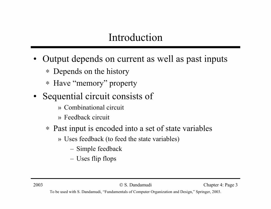
Introduction
• Output depends on current as well as past inputs∗ Depends on the history∗ Have “memory” property
• Sequential circuit consists of » Combinational circuit» Feedback circuit
∗ Past input is encoded into a set of state variables» Uses feedback (to feed the state variables)
– Simple feedback– Uses flip flops
2003To be used with S. Dandamudi, “Fundamentals of Computer Organization and Design,” Springer, 2003.
S. Dandamudi Chapter 4: Page 4
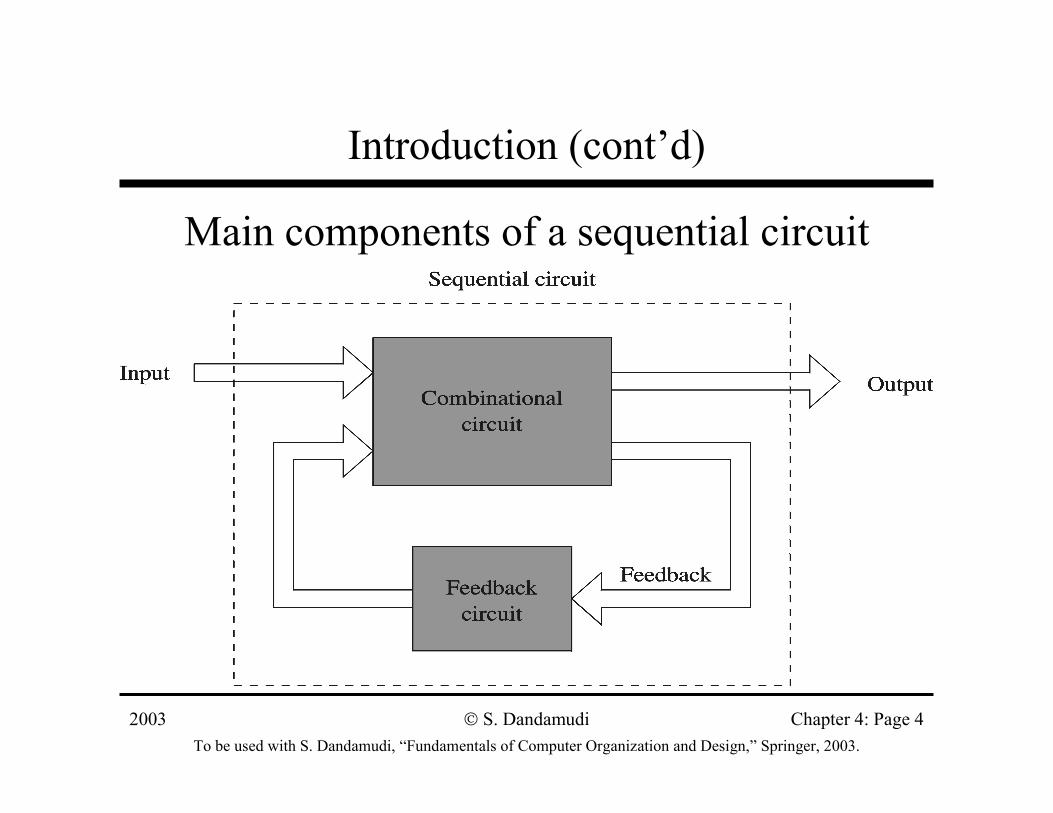
Introduction (cont’d)
Main components of a sequential circuit
2003To be used with S. Dandamudi, “Fundamentals of Computer Organization and Design,” Springer, 2003.
S. Dandamudi Chapter 4: Page 5
Introduction (cont’d)
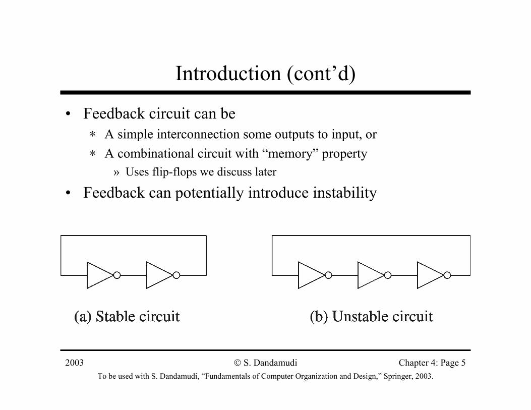
• Feedback circuit can be∗ A simple interconnection some outputs to input, or∗ A combinational circuit with “memory” property
» Uses flip-flops we discuss later
• Feedback can potentially introduce instability
2003To be used with S. Dandamudi, “Fundamentals of Computer Organization and Design,” Springer, 2003.
S. Dandamudi Chapter 4: Page 6
Clock Signal
• Digital circuits can be operated in∗ Asynchronous mode
» Circuits operate independently– Several disadvantages
∗ Synchronous mode» Circuits operate in lock-step» A common clock signal drives the circuits
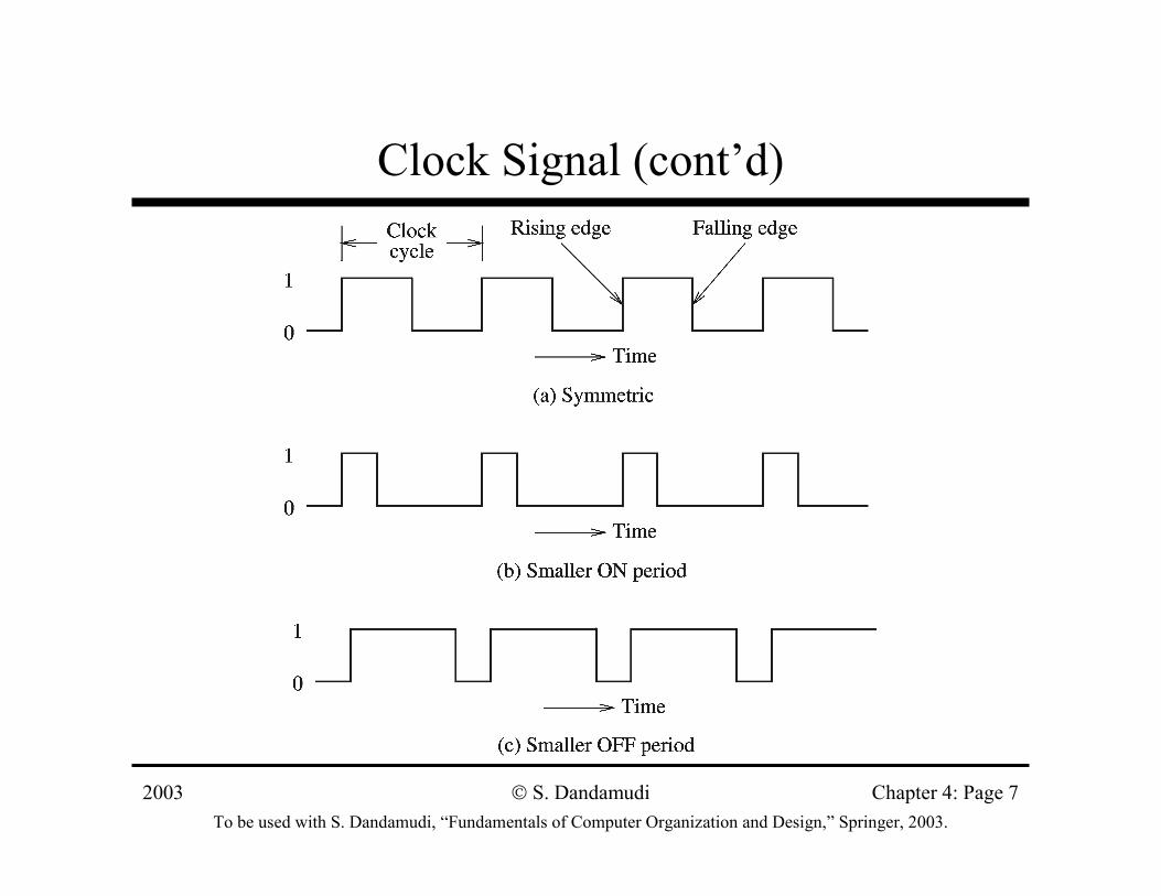
• Clock signal∗ A sequence of 1s and 0s (ON and OFF periods)∗ Need not be symmetric
2003To be used with S. Dandamudi, “Fundamentals of Computer Organization and Design,” Springer, 2003.
S. Dandamudi Chapter 4: Page 7
Clock Signal (cont’d)
2003To be used with S. Dandamudi, “Fundamentals of Computer Organization and Design,” Springer, 2003.
S. Dandamudi Chapter 4: Page 8
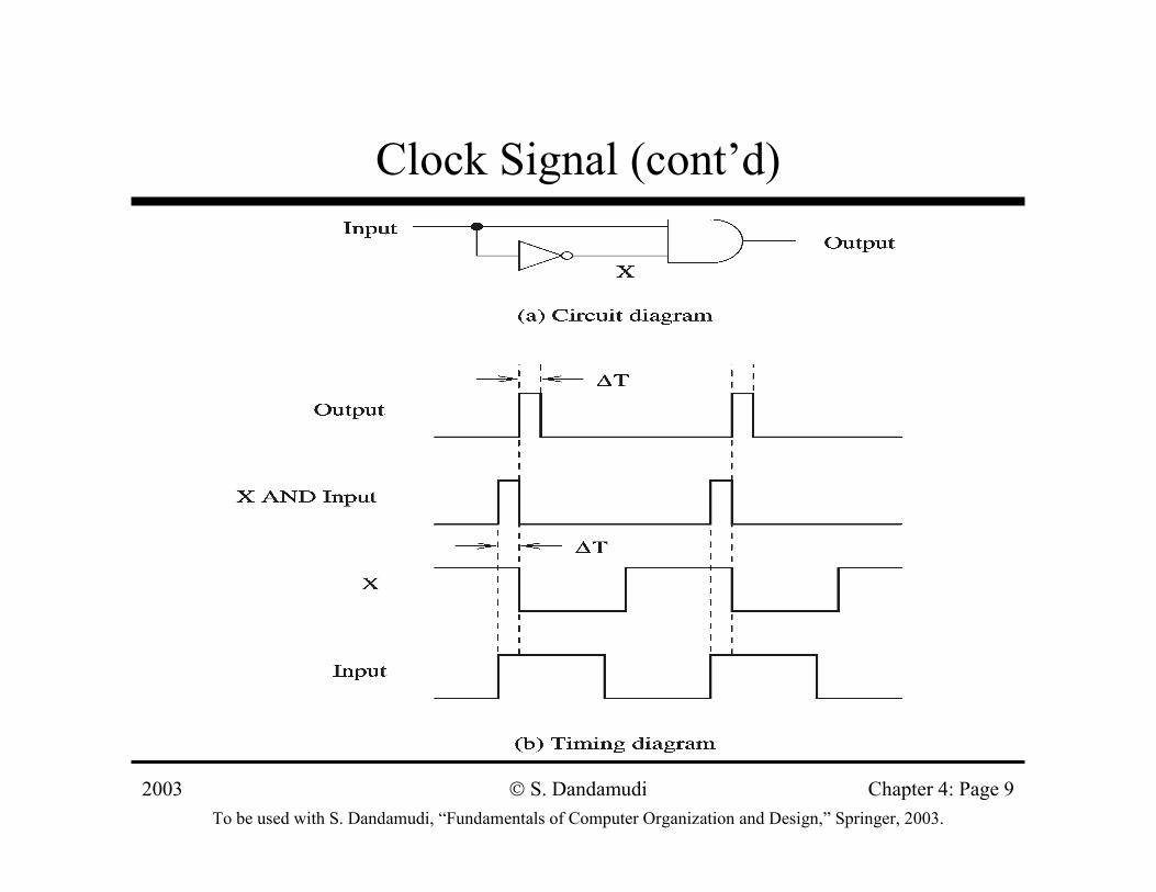
Clock Signal (cont’d)
• Clock serves two distinct purposes∗ Synchronization point
» Start of a cycle» End of a cycle» Intermediate point at which the clock signal changes levels
∗ Timing information» Clock period, ON, and OFF periods
• Propagation delay∗ Time required for the output to react to changes in the
inputs
2003To be used with S. Dandamudi, “Fundamentals of Computer Organization and Design,” Springer, 2003.
S. Dandamudi Chapter 4: Page 9
Clock Signal (cont’d)
2003To be used with S. Dandamudi, “Fundamentals of Computer Organization and Design,” Springer, 2003.
S. Dandamudi Chapter 4: Page 10
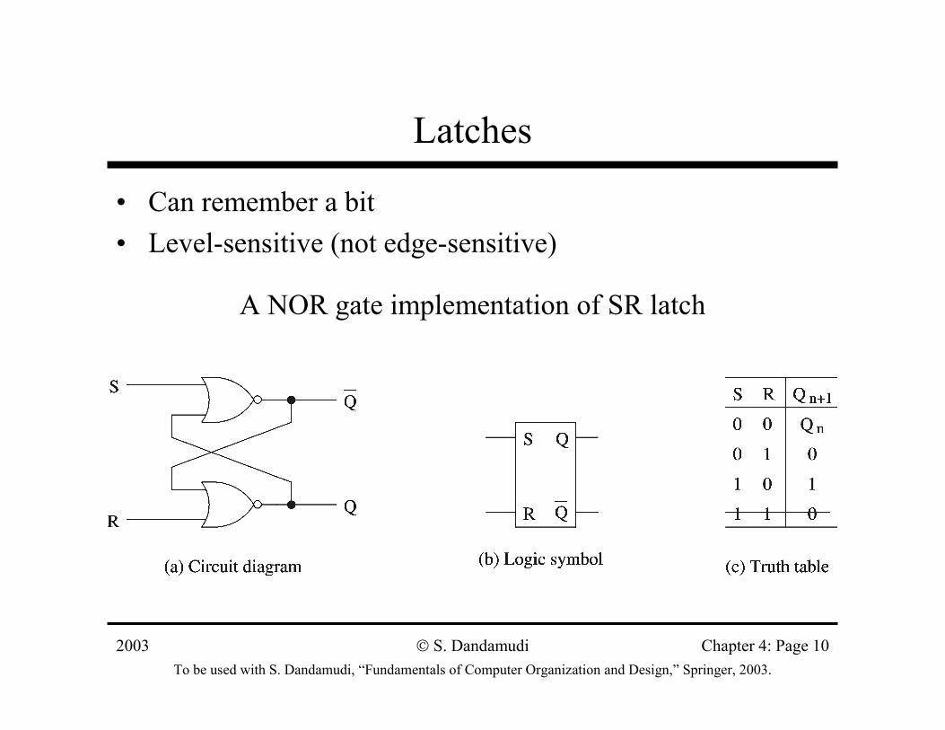
Latches
• Can remember a bit• Level-sensitive (not edge-sensitive)
A NOR gate implementation of SR latch
2003To be used with S. Dandamudi, “Fundamentals of Computer Organization and Design,” Springer, 2003.
S. Dandamudi Chapter 4: Page 11
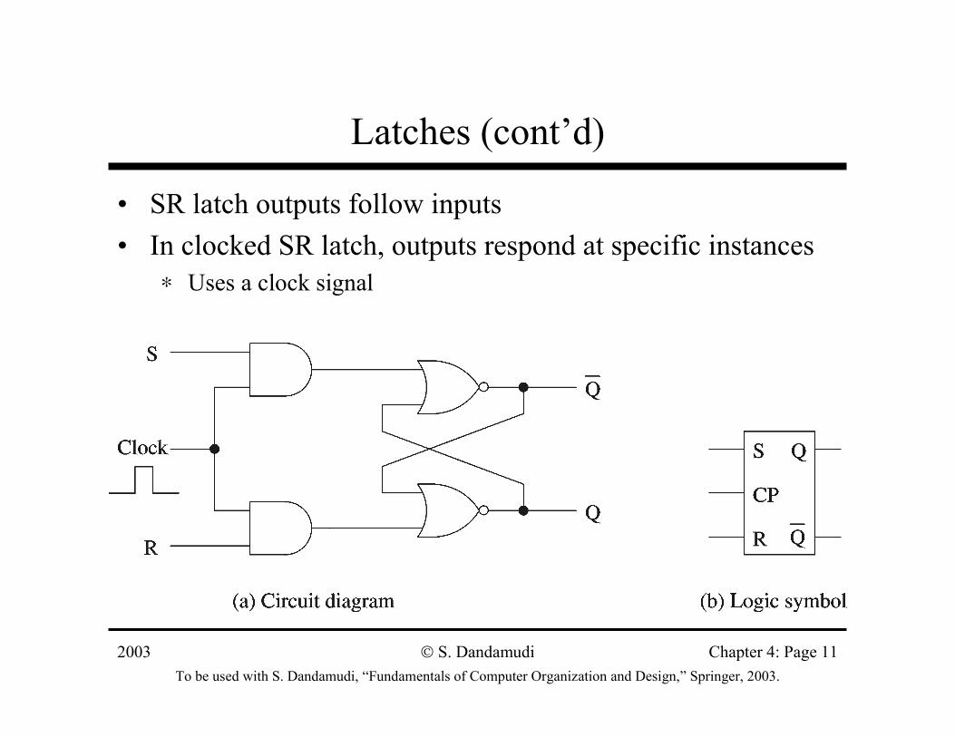
Latches (cont’d)
• SR latch outputs follow inputs• In clocked SR latch, outputs respond at specific instances
∗ Uses a clock signal
2003To be used with S. Dandamudi, “Fundamentals of Computer Organization and Design,” Springer, 2003.
S. Dandamudi Chapter 4: Page 12
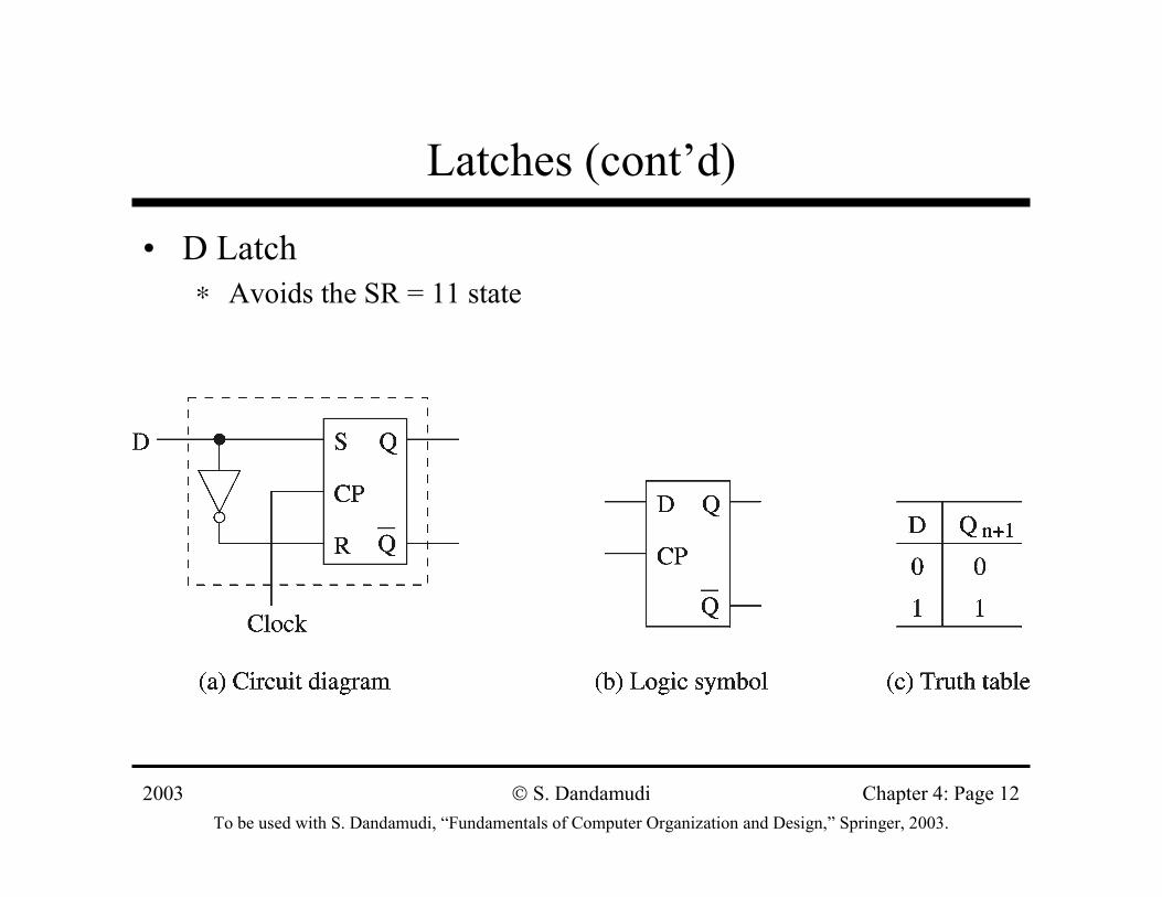
Latches (cont’d)
• D Latch∗ Avoids the SR = 11 state

2003To be used with S. Dandamudi, “Fundamentals of Computer Organization and Design,” Springer, 2003.
S. Dandamudi Chapter 4: Page 13
Flip-Flops
• Edge-sensitive devices∗ Changes occur either at positive or negative edges
Positive edge-triggered D flip-flop
2003To be used with S. Dandamudi, “Fundamentals of Computer Organization and Design,” Springer, 2003.
S. Dandamudi Chapter 4: Page 14
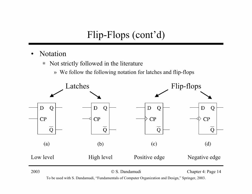
Flip-Flops (cont’d)
• Notation∗ Not strictly followed in the literature
» We follow the following notation for latches and flip-flops
Low level High level Positive edge Negative edge
Latches Flip-flops
2003To be used with S. Dandamudi, “Fundamentals of Computer Organization and Design,” Springer, 2003.
S. Dandamudi Chapter 4: Page 15
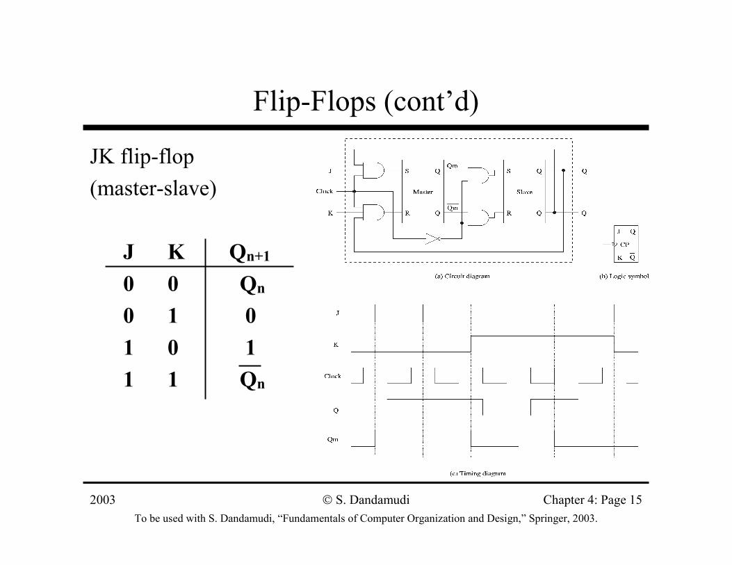
Flip-Flops (cont’d)
JK flip-flop (master-slave)
J K Qn+1
0 0 Qn
0 1 01 0 11 1 Qn
2003To be used with S. Dandamudi, “Fundamentals of Computer Organization and Design,” Springer, 2003.
S. Dandamudi Chapter 4: Page 16
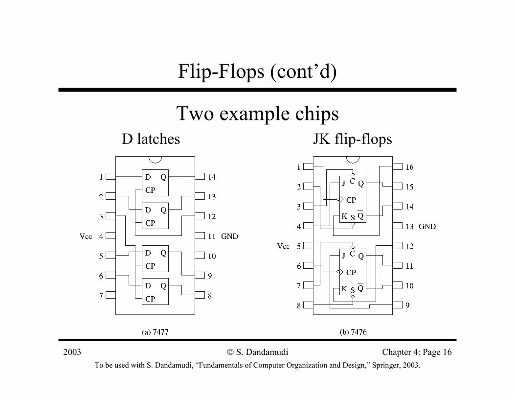
Flip-Flops (cont’d)
Two example chipsD latches JK flip-flops
2003To be used with S. Dandamudi, “Fundamentals of Computer Organization and Design,” Springer, 2003.
S. Dandamudi Chapter 4: Page 17
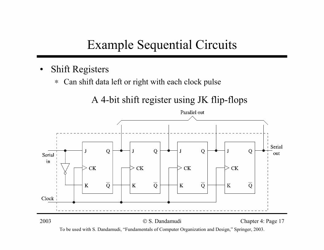
Example Sequential Circuits
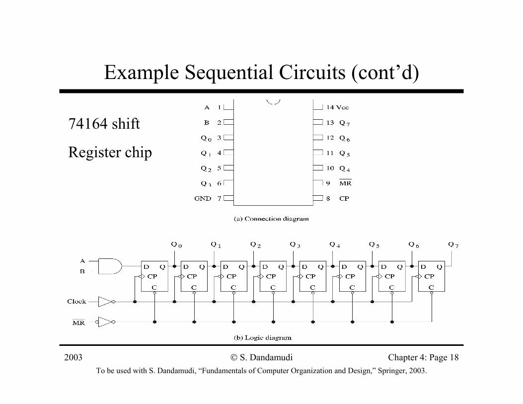
• Shift Registers∗ Can shift data left or right with each clock pulse
A 4-bit shift register using JK flip-flops
2003To be used with S. Dandamudi, “Fundamentals of Computer Organization and Design,” Springer, 2003.
S. Dandamudi Chapter 4: Page 18
Example Sequential Circuits (cont’d)
74164 shift
Register chip
2003To be used with S. Dandamudi, “Fundamentals of Computer Organization and Design,” Springer, 2003.
S. Dandamudi Chapter 4: Page 19
Example Sequential Circuits (cont’d)
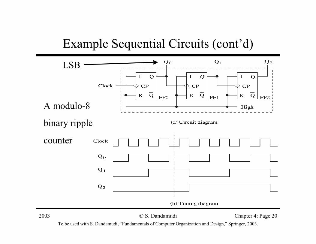
• Counters∗ Easy to build using JK flip-flops
» Use the JK = 11 to toggle∗ Binary counters
» Simple design– B bits can count from 0 to 2B−−−−1
» Ripple counter– Increased delay as in ripple-carry adders– Delay proportional to the number of bits
» Synchronous counters– Output changes more or less simultaneously– Additional cost/complexity
2003To be used with S. Dandamudi, “Fundamentals of Computer Organization and Design,” Springer, 2003.
S. Dandamudi Chapter 4: Page 20
Example Sequential Circuits (cont’d)
A modulo-8
binary ripple
counter
LSB
2003To be used with S. Dandamudi, “Fundamentals of Computer Organization and Design,” Springer, 2003.
S. Dandamudi Chapter 4: Page 21
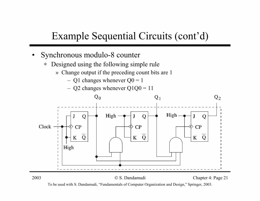
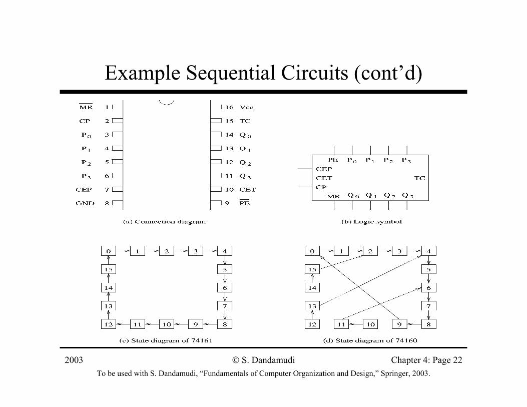
Example Sequential Circuits (cont’d)
• Synchronous modulo-8 counter∗ Designed using the following simple rule
» Change output if the preceding count bits are 1– Q1 changes whenever Q0 = 1– Q2 changes whenever Q1Q0 = 11
2003To be used with S. Dandamudi, “Fundamentals of Computer Organization and Design,” Springer, 2003.
S. Dandamudi Chapter 4: Page 22
Example Sequential Circuits (cont’d)
2003To be used with S. Dandamudi, “Fundamentals of Computer Organization and Design,” Springer, 2003.
S. Dandamudi Chapter 4: Page 23
Example Sequential Circuits (cont’d)
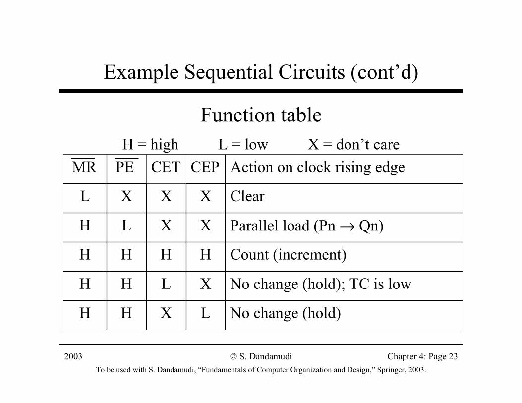
Function tableH = high L = low X = don’t care
No change (hold)LXHH
No change (hold); TC is lowXLHH
Count (increment)HHHH
Parallel load (Pn → Qn)XXLH
ClearXXXL
Action on clock rising edgeCEPCETPEMR
2003To be used with S. Dandamudi, “Fundamentals of Computer Organization and Design,” Springer, 2003.
S. Dandamudi Chapter 4: Page 24
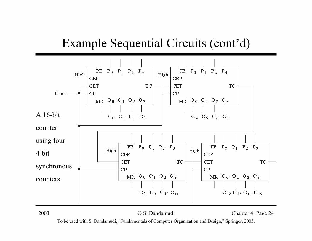
Example Sequential Circuits (cont’d)
A 16-bit
counter
using four
4-bit
synchronous
counters
2003To be used with S. Dandamudi, “Fundamentals of Computer Organization and Design,” Springer, 2003.
S. Dandamudi Chapter 4: Page 25
Sequential Circuit Design
• Sequential circuit consists of ∗ A combinational circuit that produces output∗ A feedback circuit
» We use JK flip-flops for the feedback circuit
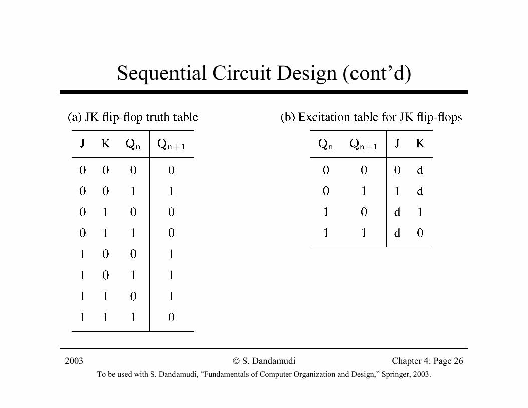
• Simple counter examples using JK flip-flops∗ Provides alternative counter designs∗ We know the output
» Need to know the input combination that produces this output» Use an excitation table
– Built from the truth table
2003To be used with S. Dandamudi, “Fundamentals of Computer Organization and Design,” Springer, 2003.
S. Dandamudi Chapter 4: Page 26
Sequential Circuit Design (cont’d)
2003To be used with S. Dandamudi, “Fundamentals of Computer Organization and Design,” Springer, 2003.
S. Dandamudi Chapter 4: Page 27
Sequential Circuit Design (cont’d)
• Build a design table that consists of∗ Current state output∗ Next state output∗ JK inputs for each flip-flop
• Binary counter example∗ 3-bit binary counter∗ 3 JK flip-flops are needed∗ Current state and next state outputs are 3 bits each∗ 3 pairs of JK inputs
2003To be used with S. Dandamudi, “Fundamentals of Computer Organization and Design,” Springer, 2003.
S. Dandamudi Chapter 4: Page 28
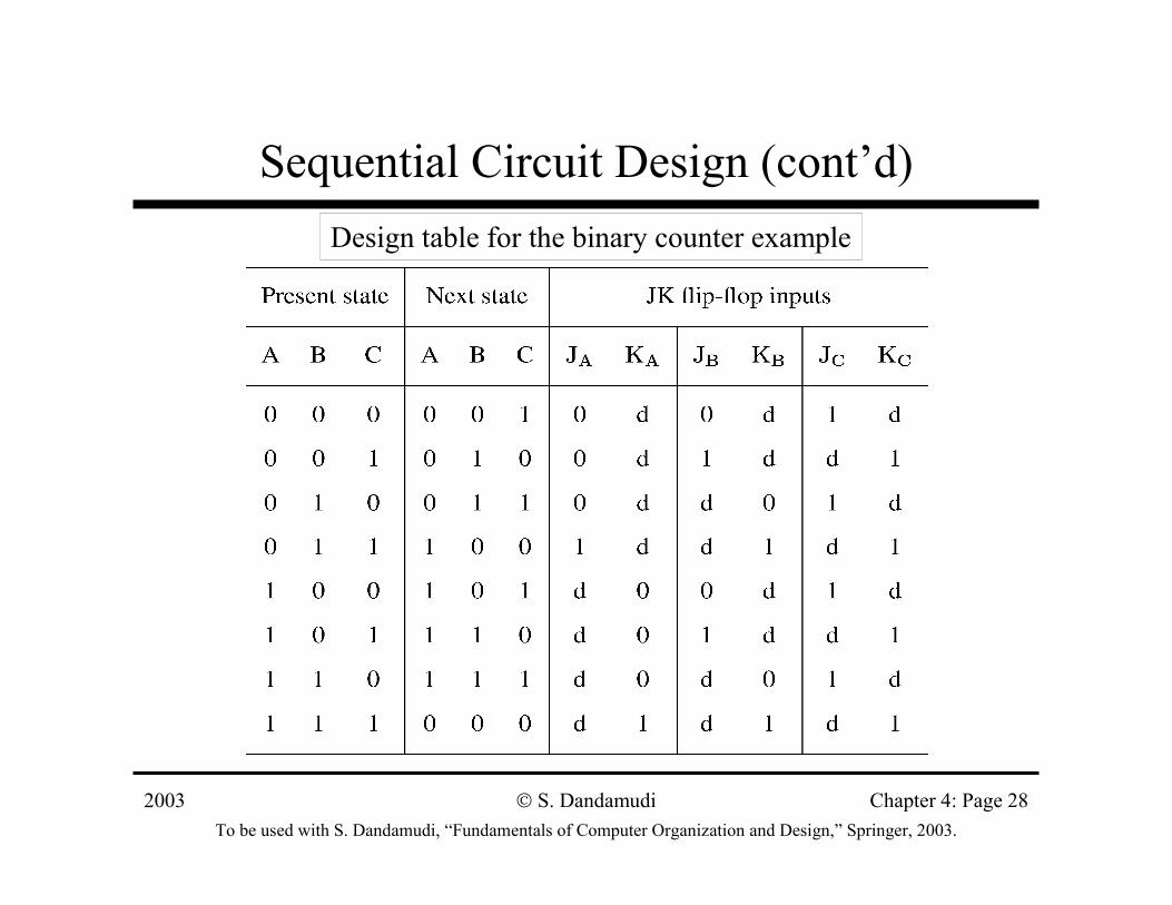
Sequential Circuit Design (cont’d)Design table for the binary counter example
2003To be used with S. Dandamudi, “Fundamentals of Computer Organization and Design,” Springer, 2003.
S. Dandamudi Chapter 4: Page 29
Sequential Circuit Design (cont’d)
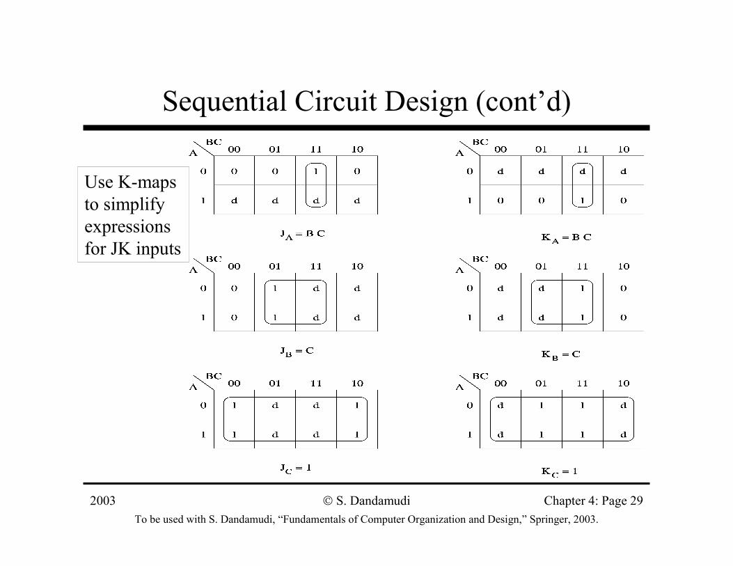
Use K-maps to simplify expressions for JK inputs
2003To be used with S. Dandamudi, “Fundamentals of Computer Organization and Design,” Springer, 2003.
S. Dandamudi Chapter 4: Page 30
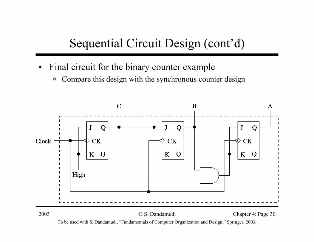
Sequential Circuit Design (cont’d)
• Final circuit for the binary counter example∗ Compare this design with the synchronous counter design
2003To be used with S. Dandamudi, “Fundamentals of Computer Organization and Design,” Springer, 2003.
S. Dandamudi Chapter 4: Page 31
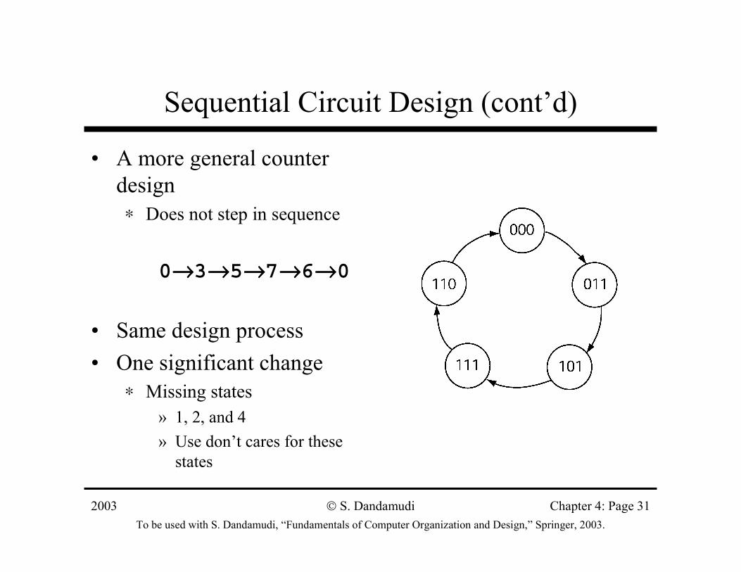
Sequential Circuit Design (cont’d)
• A more general counter design∗ Does not step in sequence
0→→→→3→→→→5→→→→7→→→→6→→→→0
• Same design process• One significant change
∗ Missing states» 1, 2, and 4» Use don’t cares for these
states
2003To be used with S. Dandamudi, “Fundamentals of Computer Organization and Design,” Springer, 2003.
S. Dandamudi Chapter 4: Page 32
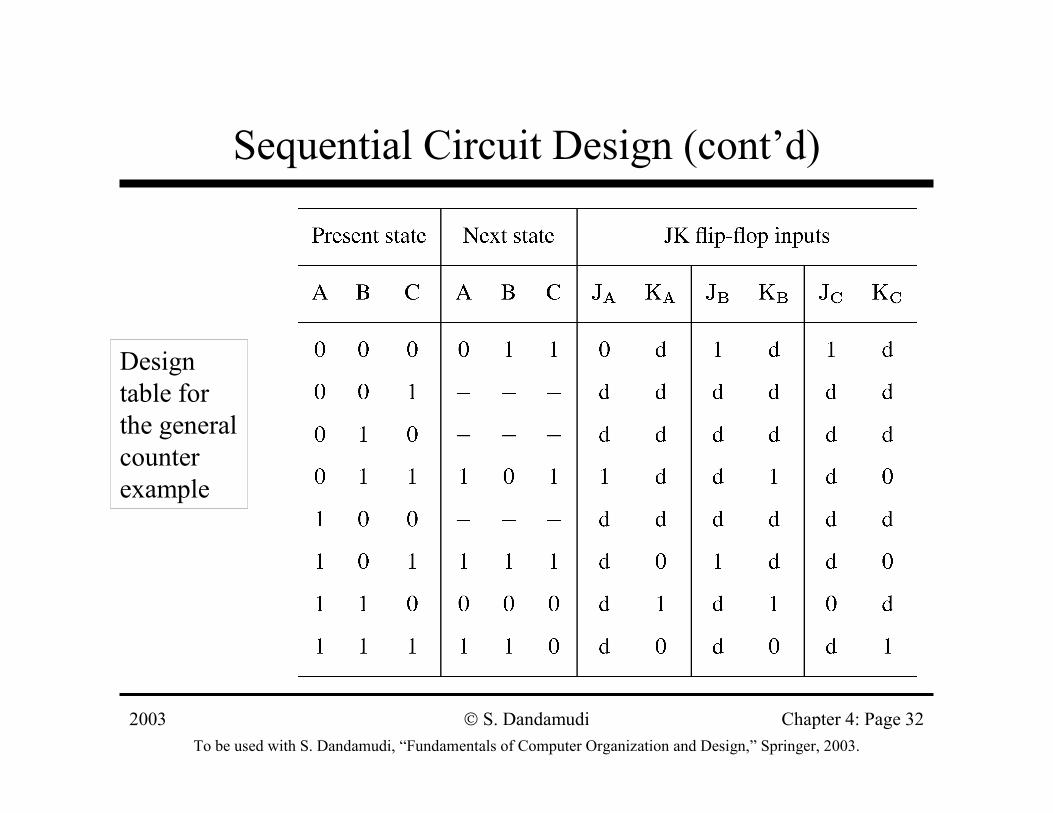
Sequential Circuit Design (cont’d)
Design table for the general counter example
2003To be used with S. Dandamudi, “Fundamentals of Computer Organization and Design,” Springer, 2003.
S. Dandamudi Chapter 4: Page 33
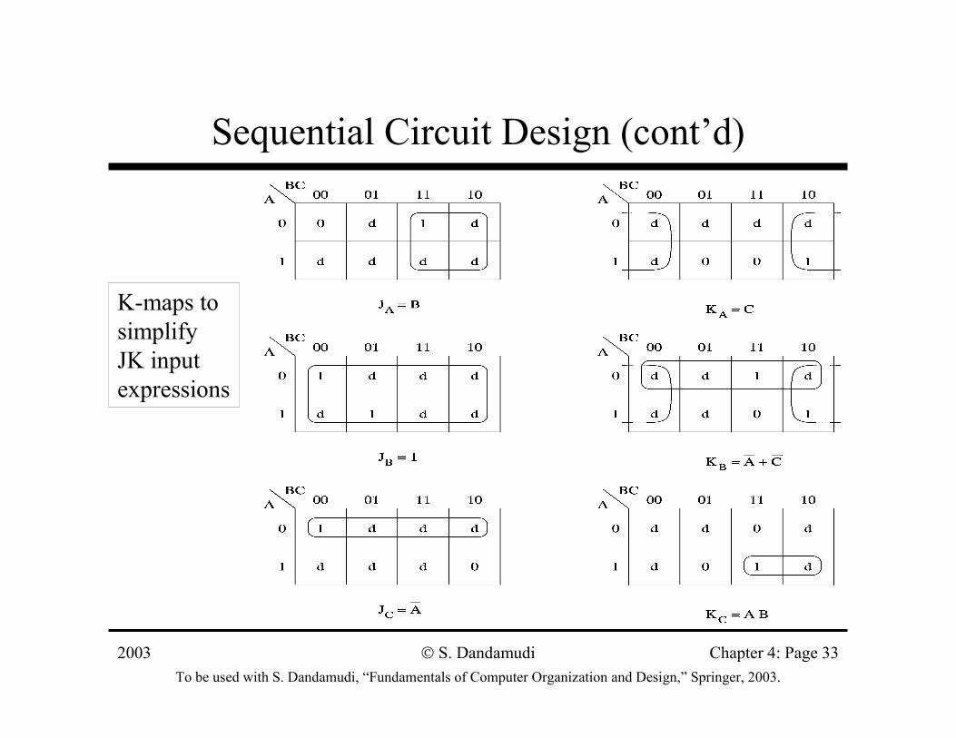
Sequential Circuit Design (cont’d)
K-maps to simplify JK input expressions
2003To be used with S. Dandamudi, “Fundamentals of Computer Organization and Design,” Springer, 2003.
S. Dandamudi Chapter 4: Page 34
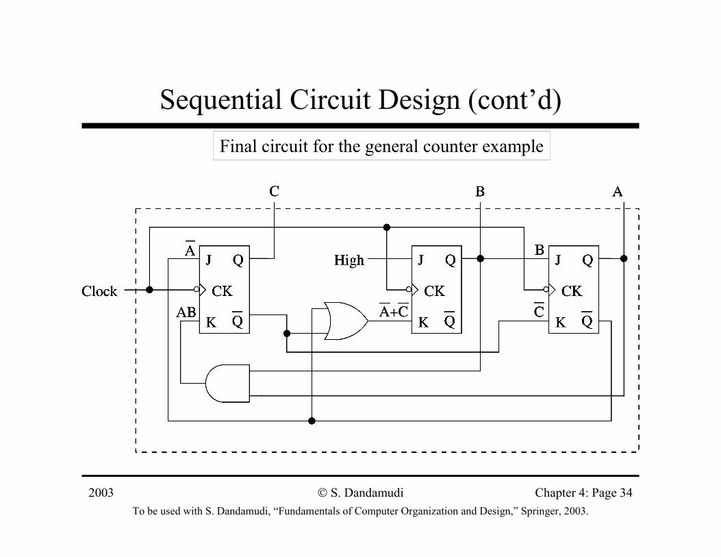
Sequential Circuit Design (cont’d)Final circuit for the general counter example
2003To be used with S. Dandamudi, “Fundamentals of Computer Organization and Design,” Springer, 2003.
S. Dandamudi Chapter 4: Page 35
General Design Process
• FSM can be used to express the behavior of a sequential circuit
» Counters are a special case
∗ State transitions are indicated by arrows with labels X/Y
» X: inputs that cause system state change» Y: output generated while moving to the next state
• Look at two examples∗ Even-parity checker∗ Pattern recognition
2003To be used with S. Dandamudi, “Fundamentals of Computer Organization and Design,” Springer, 2003.
S. Dandamudi Chapter 4: Page 36
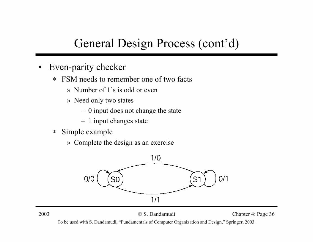
General Design Process (cont’d)
• Even-parity checker∗ FSM needs to remember one of two facts
» Number of 1’s is odd or even» Need only two states
– 0 input does not change the state– 1 input changes state
∗ Simple example » Complete the design as an exercise
2003To be used with S. Dandamudi, “Fundamentals of Computer Organization and Design,” Springer, 2003.
S. Dandamudi Chapter 4: Page 37
General Design Process (cont’d)
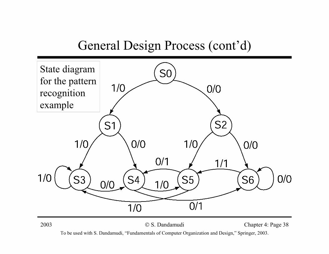
• Pattern recognition example∗ Outputs 1 whenever the input bit sequence has exactly
two 0s in the last three input bits∗ FSM requires thee special states to during the initial
phase » S0 − S2
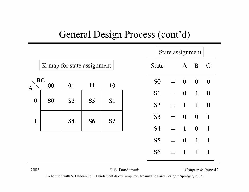
∗ After that we need four states» S3: last two bits are 11» S4: last two bits are 01» S5: last two bits are 10» S6: last two bits are 00
2003To be used with S. Dandamudi, “Fundamentals of Computer Organization and Design,” Springer, 2003.
S. Dandamudi Chapter 4: Page 38
General Design Process (cont’d)
State diagram for the pattern recognition example
2003To be used with S. Dandamudi, “Fundamentals of Computer Organization and Design,” Springer, 2003.
S. Dandamudi Chapter 4: Page 39
General Design Process (cont’d)
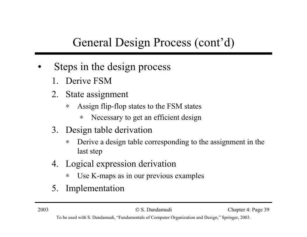
• Steps in the design process1. Derive FSM2. State assignment
∗ Assign flip-flop states to the FSM states∗ Necessary to get an efficient design
3. Design table derivation∗ Derive a design table corresponding to the assignment in the
last step
4. Logical expression derivation∗ Use K-maps as in our previous examples
5. Implementation
2003To be used with S. Dandamudi, “Fundamentals of Computer Organization and Design,” Springer, 2003.
S. Dandamudi Chapter 4: Page 40
General Design Process (cont’d)
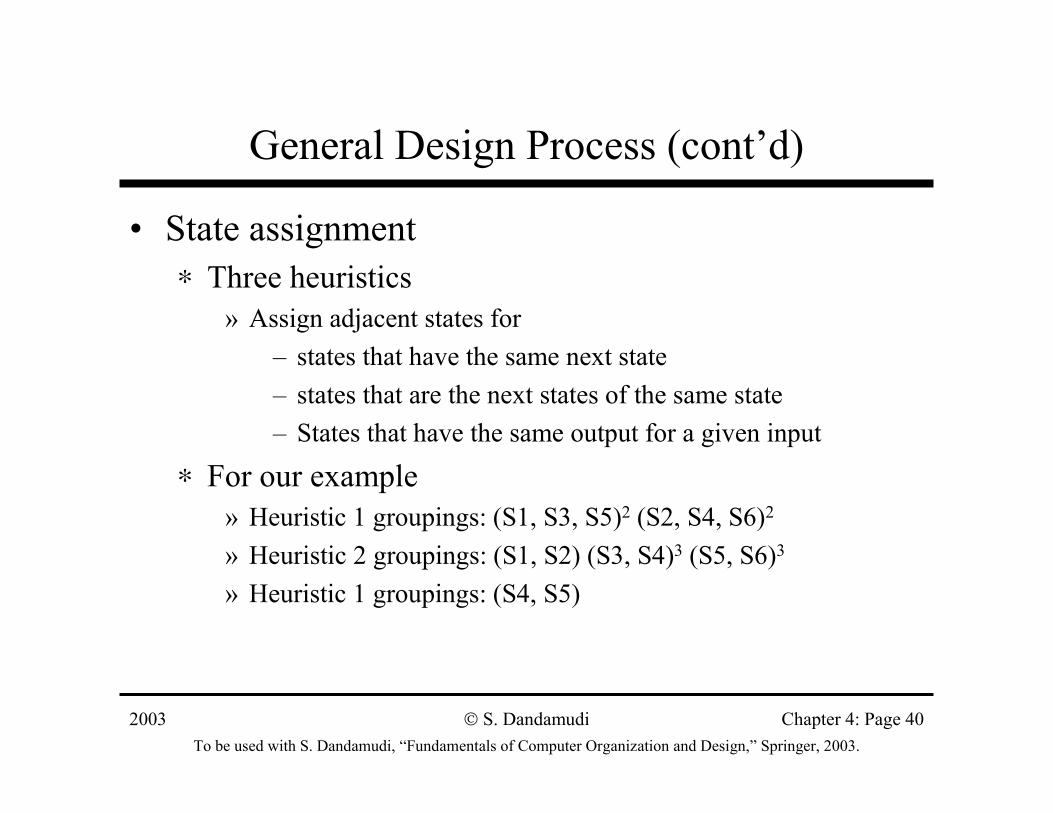
• State assignment∗ Three heuristics
» Assign adjacent states for– states that have the same next state– states that are the next states of the same state– States that have the same output for a given input
∗ For our example» Heuristic 1 groupings: (S1, S3, S5)2 (S2, S4, S6)2
» Heuristic 2 groupings: (S1, S2) (S3, S4)3 (S5, S6)3
» Heuristic 1 groupings: (S4, S5)
2003To be used with S. Dandamudi, “Fundamentals of Computer Organization and Design,” Springer, 2003.
S. Dandamudi Chapter 4: Page 41
General Design Process (cont’d)
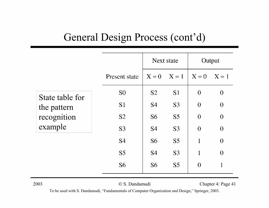
State table for the pattern recognition example
2003To be used with S. Dandamudi, “Fundamentals of Computer Organization and Design,” Springer, 2003.
S. Dandamudi Chapter 4: Page 42
General Design Process (cont’d)
State assignment
K-map for state assignment
2003To be used with S. Dandamudi, “Fundamentals of Computer Organization and Design,” Springer, 2003.
S. Dandamudi Chapter 4: Page 43
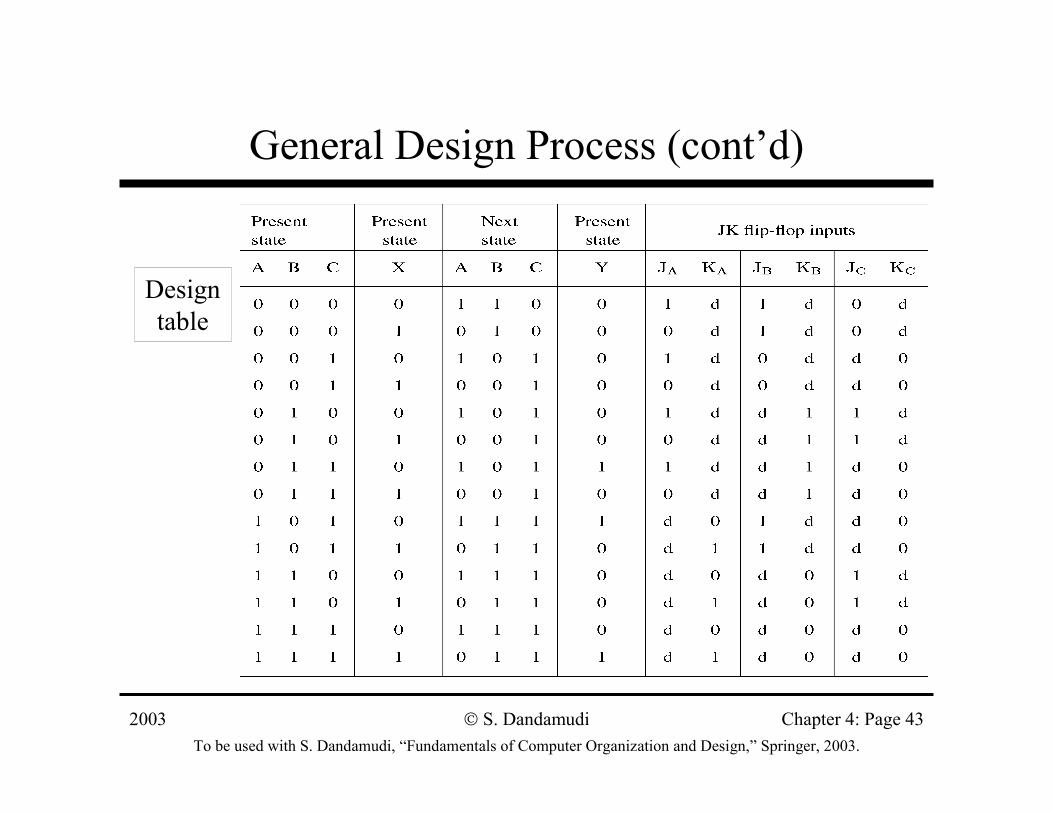
General Design Process (cont’d)
Design table
2003To be used with S. Dandamudi, “Fundamentals of Computer Organization and Design,” Springer, 2003.
S. Dandamudi Chapter 4: Page 44
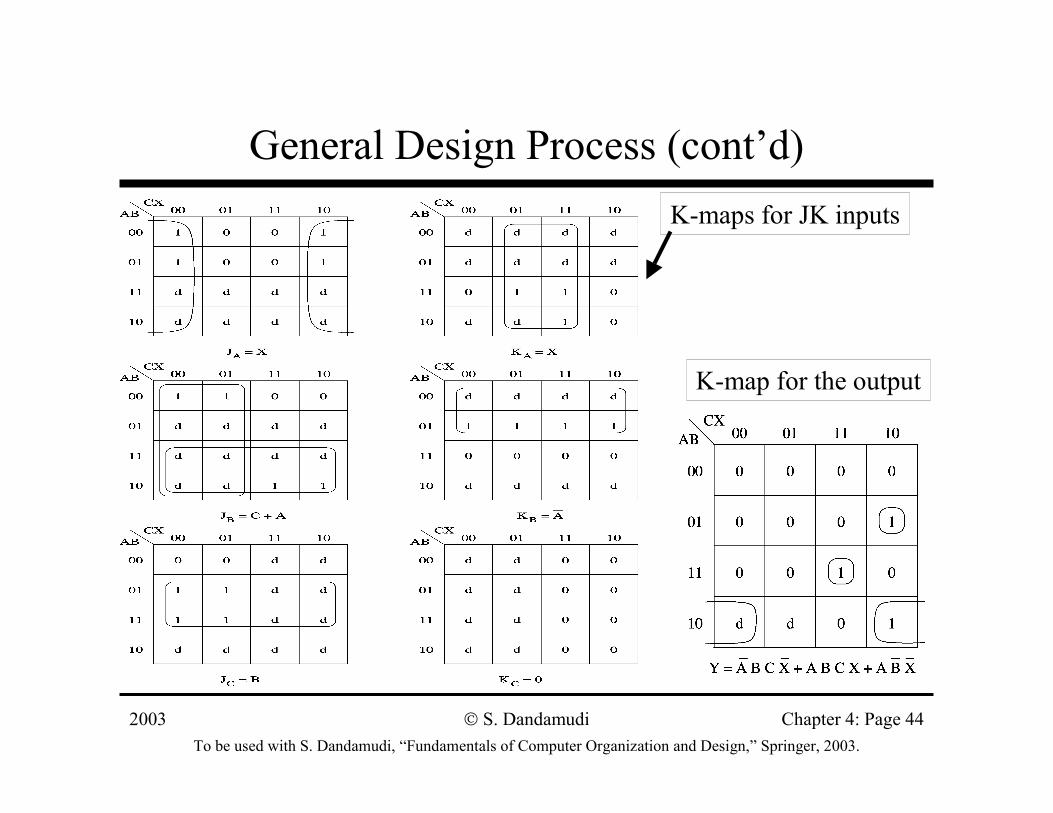
General Design Process (cont’d)K-maps for JK inputs
K-map for the output
2003To be used with S. Dandamudi, “Fundamentals of Computer Organization and Design,” Springer, 2003.
S. Dandamudi Chapter 4: Page 45
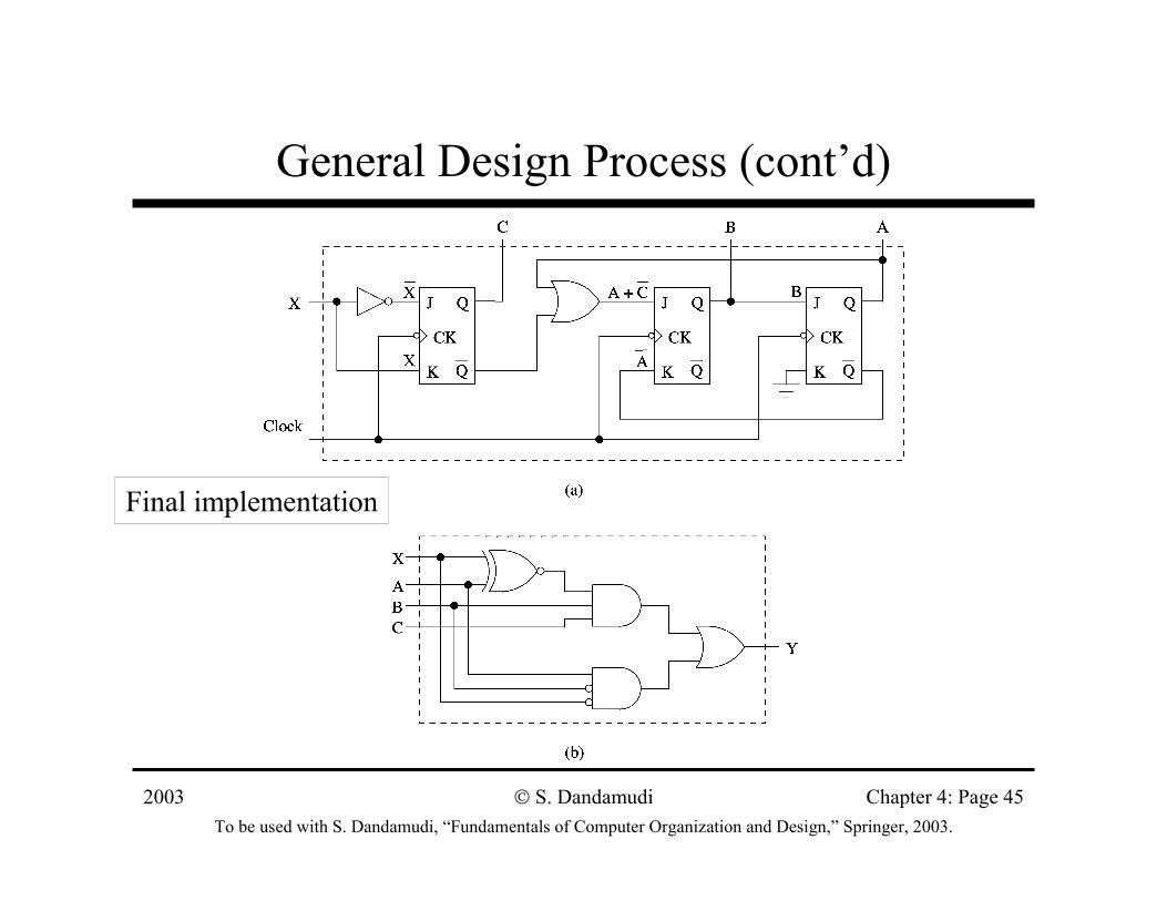
General Design Process (cont’d)
Final implementation
2003To be used with S. Dandamudi, “Fundamentals of Computer Organization and Design,” Springer, 2003.
S. Dandamudi Chapter 4: Page 46
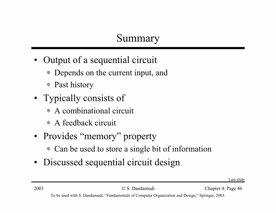
Summary
• Output of a sequential circuit∗ Depends on the current input, and∗ Past history
• Typically consists of ∗ A combinational circuit∗ A feedback circuit
• Provides “memory” property∗ Can be used to store a single bit of information
• Discussed sequential circuit designLast slide


![[XLS]data. · Web view0. 0. 2. 0. 0. 0. 0. 0. 0. 0. 0. 0. 0. 0. 0. 0. 0. 0. 0. 0. 0. 0. 0. 0. 0. 0. 0. 0. 0. 0. 0. 0. 0. 0. 0. 0. 0. 0. 0. 0. 0. 0. 0. 0. 0. 0. 0. 0. 0. 0. 0. 0. 0](https://img.pdfslide.net/doc/110x75/5ab13df97f8b9ac66c8c4034/xlsdata-view0-0-2-0-0-0-0-0-0-0-0-0-0-0-0-0-0-0-0-0-0-0.jpg)


![[XLS]mams.rmit.edu.aumams.rmit.edu.au/urs1erc4d2nv1.xlsx · Web view0. 0. 0. 0. 0. 0. 0. 0. 0. 0. 0. 0. 0. 0. 0. 0. 0. 0. 0. 0. 0. 0. 0. 0. 0. 0. 0. 0. 0. 0. 0. 0. 0. 0. 0. 0. 0](https://img.pdfslide.net/doc/110x75/5ab434027f8b9a0f058b8cff/xlsmamsrmitedu-view0-0-0-0-0-0-0-0-0-0-0-0-0-0-0-0-0-0-0.jpg)