Embed Size (px)
Citation preview
Power Transmission Products, Inc.
Service Manualfor
Industrial V-Belt Drives
Service Manualfor
Industrial V-Belt Drives
Power Transmission Products, Inc.
102163 (Rev ©2007) Carlisle Power Transmission Products, Inc.
U.S.A.
Customer Service: (866) 773-2926
CANADA
Customer Service: (866) 797-2358
www.cptbelts.com
U.S.A.
Customer Service: (866) 773-2926
CANADA
Customer Service: (866) 797-2358
www.carlislebelts.com
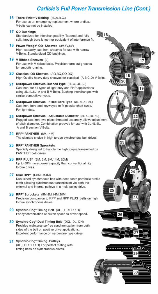
Thoro-Twist® V-Belting (3L,A,B,C,)For use as an emergency replacement where endless V-belts cannot be installed.
QD Bushings
Standardized for interchangeability. Tapered and fully split through bore length for equivalent of interference fit.
Power-Wedge® QD Sheaves (3V,5V,8V) High -capacity cast iron sheaves for use with narrow V-Belts. Standardized QD bushings.
V-Ribbed Sheaves (J)For use with V-ribbed belts. Precision form-cut grooves for smooth running.
Classical QD Sheaves (AQ,BQ,CQ,DQ)High-Quality heavy duty sheaves for classical (A,B,C,D) V-Belts.
Durapower Sheaves-Bushed Type (3L-4L,4L-5L)Cast iron, for all types of light-duty and FHP applications using 3L,4L,5L, A and B V-Belts. Bushing interchanges with similar competitive types.
Durapower Sheaves - Fixed Bore Type (3L-4L,4L-5L)Cast iron, bore and keywayed to fit popular shaft sizes. For light-duty.
Durapower Sheaves - Adjustable Diameter (3L-4L,4L-5L)Rugged cast iron, two piece threaded assembly allows adjustment of pitch diameter. Combination grooves for use with 3L,4L,5L,A and B section V-Belts.
RPP® PANTHER (8M,14M)The ultimate choice in high torque synchronous belt drives.
RPP® PANTHER Sprockets
Specially designed to handle the high torque transmitted by PANTHER belt drives.
RPP PLUS® (3M, 5M, 8M,14M, 20M)Up to 50% more power capacity than conventional high torque drives.
Dual RPP® (D8M,D14M)Dual sided synchronous belt with deep tooth parabolic profile teeth allowing synchronous transmission via both the external and internal pulleys in a multi-pulley drive.
RPP® Sprockets (5M,8M,14M,20M)Precision companion to RPP and RPP PLUS belts on high torque synchronous drives.
Synchro-Cog® Timing Belt (XL,L,H,XH,XXH)For synchronization of driven speed to driver speed.
Synchro-Cog® Dual Timing Belt (DXL, DL, DH) Provides maintenance-free synchronization from both sides of the belt on positive drive applications. Excellent performance on serpentine type drives.
Synchro-Cog® Timing Pulleys
(XL,L,H,XH,XXH) For perfect mating withtiming belts on synchronous drives.
16
17
18
19
20
21
22
23
24
25
26
27
28
29
30
31
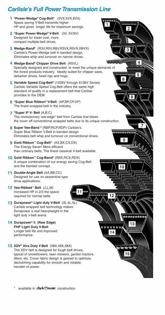
*Power-Wedge® Cog-Belt® (3VX,5VX,8VX) Space saving V-Belt transmits higher HP and gives longer life for maximum savings.
*Super Power-Wedge® V-Belt (3V, 5V,8V)Designed for lower cost, more compact multiple-belt drives.
Wedge-Band® (R3V,R5V,R8V,R3VX,R5VX,R8VX)Carlisle's Power-Wedge belt in banded design. Eliminates whip and turnover on narrow drives.
Wedge-Band® Chipper Drive Belt (R5VL) Specially designed and constructed to meet the unique demands of the forest products industry. Ideally suited for chipper saws,debarker drives, head rigs and hogs.
Variable Speed Cog-Belt® (1228V through 6136V Series)Carlisle Variable Speed Cog-Belt offers the same high standard of quality in a replacement belt that Carlisle provides to the OEM.
*Super Blue Ribbon® V-Belt (AP,BP,CP,DP) The finest wrapped belt in the industry.
*Super II® V- Belt (A,B,C)The revolutionary raw-edge® belt from Carlisle that blows the cover off conventional wrapped belts due to its unique construction.
Super Vee-Band ® (RBP,RCP,RDP) Carlisle’s Super Blue Ribbon V-Belt in banded design. Eliminates belt whip and turnover on conventional drives.
Gold Ribbon™ Cog-Belt® (AX,BX,CX,DX)The Energy Saver! More efficientthan ordinary belts. The finest classical V-belt available.
Gold Ribbon™ Cog-Band® (RBX,RCX,RDX)A unique combination of our energy saving Cog-Belt and the banded concept.
Double-Angle Belt (AA,BB,CC)Designed for use on serpentine type drive applications.
Vee-Ribbed™ Belt (J,L,M)Increased HP in 2/3 the space required for normal belts.
Durapower® Light duty V-Belt (3L,4L,5L) Carlisle wrapped belt technology makesDurapower a real heavyweight in thelight duty v-belt arena.
Durapower® ll (Raw Edge)
FHP Light Duty V-Belt
Longer belt life and improved performance.
XDV® Xtra Duty V-Belt (38X,48X,58X)The XDV belt is designed for tough belt drives; typical of snowblowers, lawn mowers, garden tractors, tillers, etc. Cover fabric design is geared to optimize declutching capability for smooth and reliable transfer of power.
* available in construction
Carlisle’s Full Power Transmission Line
1
2
3
4
5
6
7
8
9
10
11
12
13
14
15
12
3
6
4
5
8
7
Carlisle’s Full Power Transmission Line (Cont.)
16
18
17
19
21
23
24
22
26
31
20
25
28
9
11
10
12
27
29
30
14
13
15
1
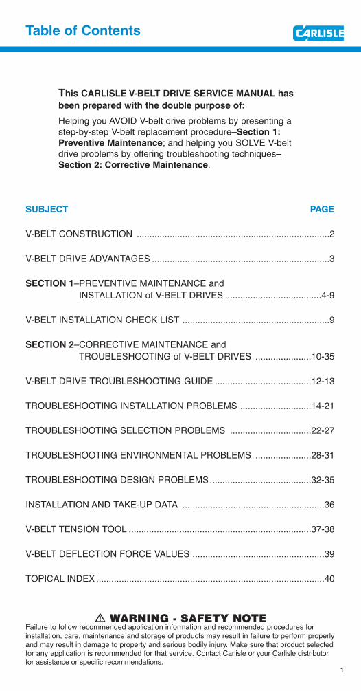
Table of Contents
This CARLISLE V-BELT DRIVE SERVICE MANUAL has
been prepared with the double purpose of:
Helping you AVOID V-belt drive problems by presenting astep-by-step V-belt replacement procedure–Section 1:
Preventive Maintenance; and helping you SOLVE V-belt drive problems by offering troubleshooting techniques–Section 2: Corrective Maintenance.
SUBJECT PAGE
V-BELT CONSTRUCTION ............................................................................2
V-BELT DRIVE ADVANTAGES ......................................................................3
SECTION 1–PREVENTIVE MAINTENANCE andINSTALLATION of V-BELT DRIVES ......................................4-9
V-BELT INSTALLATION CHECK LIST ..........................................................9
SECTION 2–CORRECTIVE MAINTENANCE andTROUBLESHOOTING of V-BELT DRIVES ......................10-35
V-BELT DRIVE TROUBLESHOOTING GUIDE ......................................12-13
TROUBLESHOOTING INSTALLATION PROBLEMS ............................14-21
TROUBLESHOOTING SELECTION PROBLEMS ................................22-27
TROUBLESHOOTING ENVIRONMENTAL PROBLEMS ......................28-31
TROUBLESHOOTING DESIGN PROBLEMS........................................32-35
INSTALLATION AND TAKE-UP DATA ........................................................36
V-BELT TENSION TOOL ........................................................................37-38
V-BELT DEFLECTION FORCE VALUES ....................................................39
TOPICAL INDEX ..........................................................................................40
! WARNING - SAFETY NOTEFailure to follow recommended application information and recommended procedures forinstallation, care, maintenance and storage of products may result in failure to perform properlyand may result in damage to property and serious bodily injury. Make sure that product selectedfor any application is recommended for that service. Contact Carlisle or your Carlisle distributorfor assistance or specific recommendations.
2
V-Belt Construction
Wrapped Belt1. Cover–Woven cotton fabric
impregnated with neoprene.2. Tension Section–Synthetic rubber
specially compounded to stretch as belt bends around sheaves.
3. Cords–High-strength, synthetic fiber cords carry the horsepower load and minimize stretching.
4. Compression Section–Syntheticrubber compounded to support cords evenly and compress whilebending around sheaves.
Raw Edge® Cog-Belt®
1. Tension Section–Specially woven stress-relieved fabric stretches up to 176% more than ordinary bias-cut fabric.
2. Cords–Synthetic Hi-Modulus cords form the strength member to carry high loads with minimum stretching.
3. Compression Section–ExclusiveStiflex® rubber compounds and precision molded cogs increase flexibility while supporting cords evenly.
4. Raw Edge® Sidewalls–Provide uniform, anti-slip surface, greater flexibility and allows more cord width.
Wrapped Belt Raw Edge® Cog-Belt®
1
2
4
1
2
4
3
3
Before we talk about “Avoiding Problems” and “Solving
Problems”, let’s take a brief look at how V-belts are
constructed.
There are basically two types of construction. One has a fabric cover surrounding it; the other–usually rated higher in horsepower–is made in araw edge, cogged construction.
3
V-Belt Drive Advantages
V-belt drives provide many maintenance advantages that help in your dailystruggle to reduce equipment repairs and to hold forced downtime to thelowest possible level.
1. They are rugged–they will give years of
trouble-free performance when given
minimal attention...even under
adverse conditions.
2. They are clean–require no lubrication.
3. They are efficient–performing with an
average of 93-95% efficiency.
4. They are smooth starting and running.
5. They cover extremely wide horsepower
ranges.
6. They permit a wide range of driven
speeds, using standard electric motors.
7. They dampen vibration between driving
and driven machines.
8. They are quiet.
9. They act as a “safety fuse” in the power-
train.
10. V-belts and sheaves wear gradually–
making preventive and corrective
maintenance simple and easy.
4
Section 1
Preventive
Maintenance
and Installation
of V-Belt Drives
You will notice Reference Key
Numbers (such as -1)appearthroughout this section. These referto a more detailed discussion withillustrations relating to the subject inSection 2 (Corrective Maintenanceand Troubleshooting).
A
Safety FirstBefore doing any maintenance work on power drives, be sure the controllingswitch is in the OFF position, locked out and tagged. Follow your plant’ssafety rules.
5
Preventive Maintenance and Installation of V-Belt Drives
Relieve Belt Tension
-1
After removing the drive guard,loosen the drive take-up and movethe sheaves closer together to facilitate the removal of all old belts,and to insure installation of the newbelts without damage.
Inspect Drive Elements
-1 -6This is a good time to service thetake-up rails by removing any rustand dirt, and lubricating as necessaryso tensioning of the new belts will gosmoothly and easily. You now alsohave an excellent opportunity toinspect and replace faulty or damagedmachine elements such as wornbearings and bent shafts.This procedure not only reduces thelikelihood of future mechanical trouble,but insures maximum service fromthe new belts you are about to install.Sheaves should be carefully cleanedof any rust and foreign material. Awire brush followed up with a shopcloth will usually do the job.
A
AA
6
Section 1
Inspect Sheaves
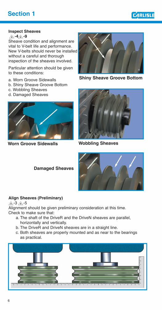
-4 -9
Sheave condition and alignment arevital to V-belt life and performance.New V-belts should never be installedwithout a careful and thoroughinspection of the sheaves involved.Particular attention should be givento these conditions:a. Worn Groove Sidewallsb. Shiny Sheave Groove Bottomc. Wobbling Sheavesd. Damaged Sheaves
Align Sheaves (Preliminary)
-3 -5Alignment should be given preliminary consideration at this time. Check to make sure that:
a. The shaft of the DriveR and the DriveN sheaves are parallel, horizontally and vertically.
b. The DriveR and DriveN sheaves are in a straight line.c. Both sheaves are properly mounted and as near to the bearings
as practical.
A A
Shiny Sheave Groove Bottom
Wobbling SheavesWorn Groove Sidewalls
Damaged Sheaves
A A
7
Preventive Maintenance and Installation of V-Belt Drives
Select Replacement Belts
-1 -2 -3 -4After you have made any necessary corrections in your V-belt drive ele-ments, the next step is the selection of the right replacement belts.In replacing sets of V-belts, here are some Very Important Reminders:
• NEVER MIX NEW AND USED BELTS ON A DRIVE.
• NEVER MIX BELTS FROM MORE THAN ONE MANUFACTURER.
• ALWAYS REPLACE WITH THE RIGHT TYPE OF V-BELT.
• ALWAYS OBSERVE V-BELT MATCHING LIMITS.
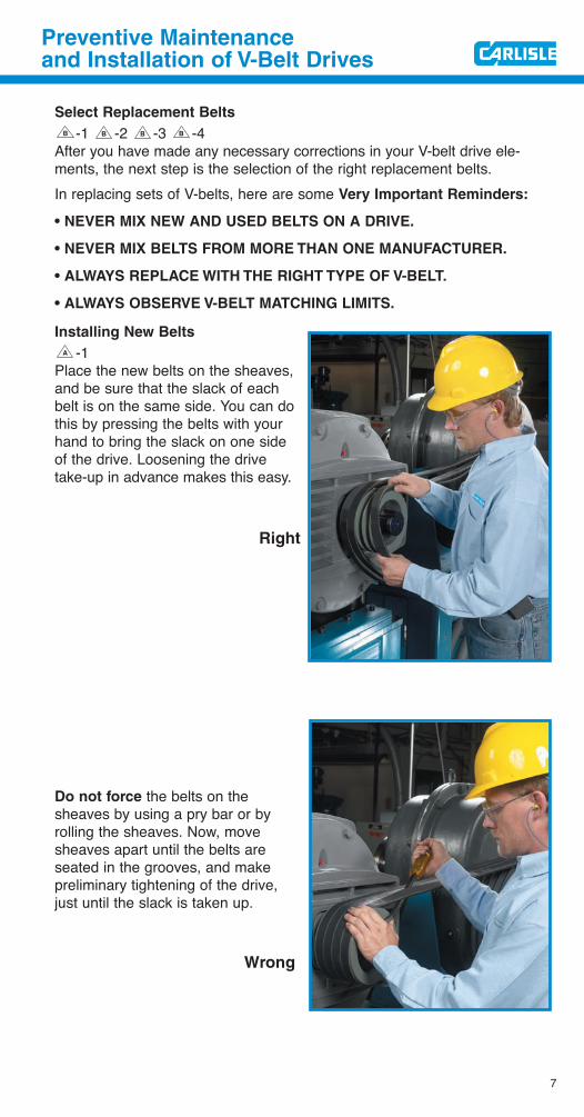
Installing New Belts
-1Place the new belts on the sheaves,and be sure that the slack of eachbelt is on the same side. You can dothis by pressing the belts with yourhand to bring the slack on one sideof the drive. Loosening the drivetake-up in advance makes this easy.
Do not force the belts on thesheaves by using a pry bar or byrolling the sheaves. Now, movesheaves apart until the belts areseated in the grooves, and makepreliminary tightening of the drive,just until the slack is taken up.
A
BBBB
Right
Wrong

Apply Tension
-7 -8All V-belt drives must operate under proper tension to produce the wedgingaction of the belt against the groove sidewall. A well-established rule ofthumb is that the best tension for a V-belt drive is the LEAST tension atwhich the drive will not slip under peak load.
Most V-belt problems are due toimproper tensioning. Several tools andmethods are available to insure propertensioning. A simple and easy to useoption is the Tension-Finder™ availableonly from Carlisle.
Run the drive for about 15 minutes.Then apply full load and check for slipping. Should slipping occur, further tension should be applied.After the drive has operated under load long enough for the belts tobecome seated and adjusted (approximately 24 hours), it is a good idea tomake a final tension inspection.For a complete discussion on tensioning and slippage, refer to Section 2
-7, in this manual.You have now completed a practical procedure for replacing V-belts thatshould help you AVOID problems with your V-belt drives. The check list onpage 9 serves to summarize the points discussed in this section.
Check Sheave Alignment (Final)-3
One of the advantages of V-belt drives is the fact that perfect alignment ofsheaves is not critical to the operation of the drive–V-belts tolerate mis-alignment of up to 1/16 inch per 12 inches of shaft center distance.However, the closer you can come to perfect alignment, the better.Laser Alignment
-3Use a laser alignment tool or straight edge to check alignment. The straightedge should make contact at four distinct points along the outside perimeterof both sheaves.
Refer to Section 2, -3, for complete discussion of proper alignment procedures.Note: Sheaves should always be mounted as close to the bearings aspractical to avoid excessive loads on bearings and shafts.
A
A
A
AA
8
Section 1
Contact points
Laser alignment toolStraight edge
A
9
Preventive Maintenance and Installation of V-Belt Drives
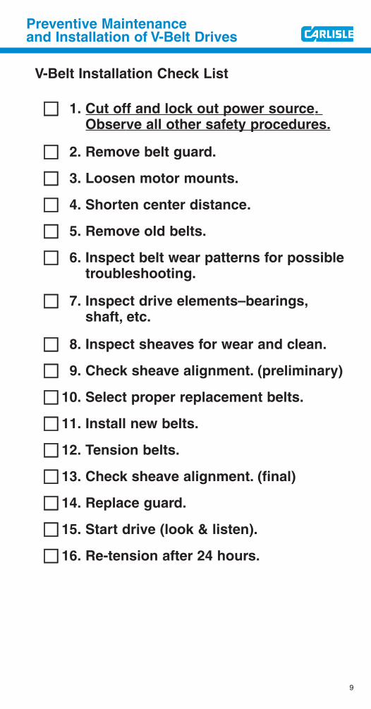
V-Belt Installation Check List
!! 1. Cut off and lock out power source.Observe all other safety procedures.
!! 2. Remove belt guard.
!! 3. Loosen motor mounts.
!! 4. Shorten center distance.
!! 5. Remove old belts.
!! 6. Inspect belt wear patterns for possible troubleshooting.
!! 7. Inspect drive elements–bearings,shaft, etc.
!! 8. Inspect sheaves for wear and clean.
!! 9. Check sheave alignment. (preliminary)
!! 10. Select proper replacement belts.
!! 11. Install new belts.
!! 12. Tension belts.
!! 13. Check sheave alignment. (final)
!! 14. Replace guard.
!! 15. Start drive (look & listen).
!! 16. Re-tension after 24 hours.
10
Section 2
Corrective
Maintenance
and Troubleshooting
of V-Belt Drives
The first section of this V-BeltService Manual outlined a step-by-step procedure for the installation ofreplacement V-belts to help you prevent V-belt maintenance problems.The reason behind these steps isalso fundamental in the daily inspec-tion and maintenance of V-beltdrives. Watching and listening willalert you to warning signs of trouble,since one of the greatest advantagesof V-belt drives is the fact that beltsand sheaves wear gradually. Youcan spot potential problems in timeto arrange a short, scheduled main-tenance down-time instead of expe-riencing a longer, costly interruptionof production when unexpectedtrouble occurs.V-belts may be thought of as beingmuch like electrical fuses–theirunexpected failure is usually a signalthat something else in the system iswrong. Even their patterns of gradualwear can often indicate conditionsneeding corrections or improvement.
11
Corrective Maintenance and Troubleshooting of V-Belt Drives
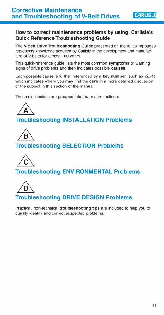
How to correct maintenance problems by using Carlisle’s
Quick Reference Troubleshooting Guide
The V-Belt Drive Troubleshooting Guide presented on the following pagesrepresents knowledge acquired by Carlisle in the development and manufac-ture of V-belts for almost 100 years.This quick-reference guide lists the most common symptoms or warningsigns of drive problems and then indicates possible causes.
Each possible cause is further referenced by a key number (such as -1)which indicates where you may find the cure in a more detailed discussionof the subject in this section of the manual.
These discussions are grouped into four major sections:
Troubleshooting INSTALLATION Problems
Troubleshooting SELECTION Problems
Troubleshooting ENVIRONMENTAL Problems
Troubleshooting DRIVE DESIGN Problems
Practical, non-technical troubleshooting tips are included to help you toquickly identify and correct suspected problems.
A
A
B
C
D
12
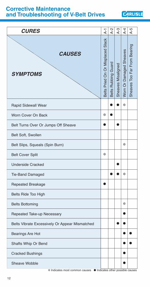
Corrective Maintenance and Troubleshooting of V-Belt Drives
CURES
CAUSES
SYMPTOMS
Rapid Sidewall Wear
Worn Cover On Back
Belt Turns Over Or Jumps Off Sheave
Belt Soft, Swollen
Belt Slips, Squeals (Spin Burn)
Belt Cover Split
Underside Cracked
Tie-Band Damaged
Repeated Breakage
Belts Ride Too High
Belts Bottoming
Repeated Take-up Necessary
Belts Vibrate Excessively Or Appear Mismatched
Bearings Are Hot
Shafts Whip Or Bend
Cracked Bushings
Sheave Wobble
A-1
A-2
A-3
A-4
A-5
❉ Indicates most common causes ● Indicates other possible causes
● ● ❉
❉ ●
● ●
❉
❉
●
● ● ❉
●
❉
●
● ●
● ●
● ●
●
●
Belts
Prie
d O
n O
r Misp
lace
d Sl
ack
Belts
Rub
bing
Gua
rdSh
eave
s M
isalig
ned
Wor
n O
r Dam
aged
She
aves
Shea
ves
Too
Far F
rom
Bea
ring
13
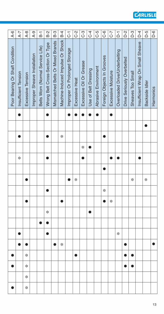
● ● ● ● ● ● ● ●
●
● ● ❉ ●
❉ ●
❉ ● ● ● ● ●
●
● ● ❉ ❉ ❉
● ❉
● ● ● ❉
❉ ●
● ●
● ● ❉
● ● ● ❉ ●
● ❉ ● ● ●
● ❉ ● ●
❉
● ❉
Poor
Bea
ring
Or S
haft
Cond
ition
Insu
fficie
nt T
ensio
nEx
cess
ive T
ensio
nIm
prop
er S
heav
e In
stal
latio
nBe
lts W
orn
(Nor
mal
Ser
vice
Life
)W
rong
Bel
t Cro
ss-S
ectio
n O
r Typ
eM
ismat
ched
Bel
ts O
r Mixe
d Br
ands
Mac
hine
-Indu
ced
Impu
lse O
r Sho
ckIm
prop
er O
r Pro
long
ed S
tora
geEx
cess
ive H
eat
Exce
ssive
Oil
Or G
reas
eUs
e of
Bel
t Dre
ssin
gAb
rasiv
e En
viron
men
tFo
reig
n O
bjec
ts In
Gro
oves
Exce
ssive
Moi
stur
eO
verlo
aded
Driv
e/Un
derb
eltin
gDr
ive S
erio
usly
Ove
rbel
ted
Shea
ves
Too
Smal
lIn
suffi
cient
Wra
p O
n Sm
all S
heav
eBa
cksid
e Id
ler
Harm
onics
A-6
A-7
A-8
A-9
B-1
B-2
B-3
B-4
C-1
C-2
C-3
C-4
C-5
C-6
C-7
D-1
D-2
D-3
D-4
D-5
D-6
●
14
Troubleshooting
Installation
Problems
As pointed out in Section 1 of thismanual, preventive maintenance byusing proper installation techniquesis important for long, trouble-free V-belt service.Occasionally, however, you will findit necessary to correct problemscaused by improper installation.This section deals with these problems and troubleshooting procedures.
15
Troubleshooting Installation Problems
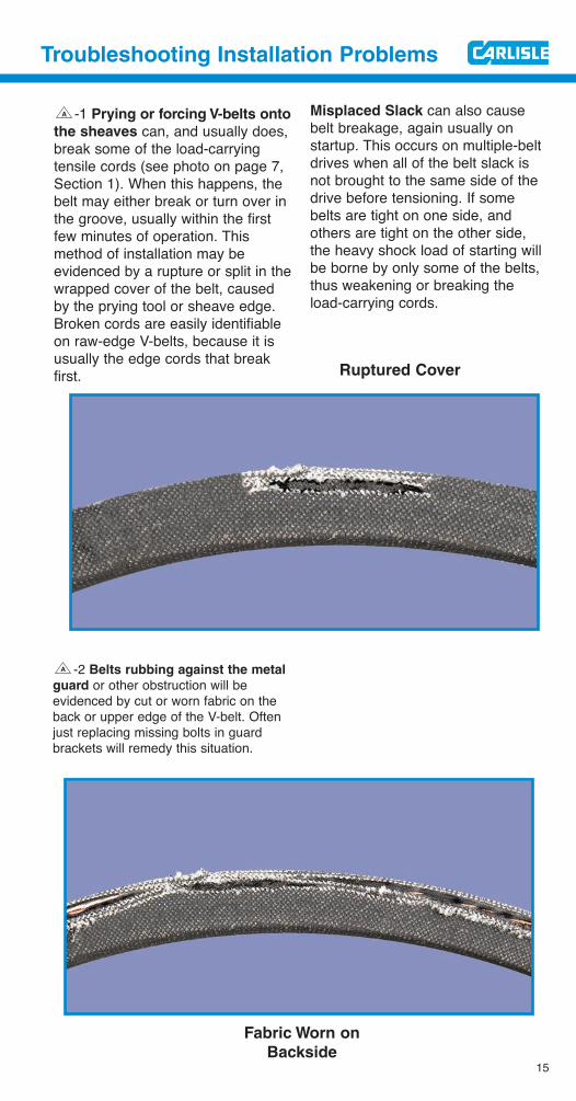
-1 Prying or forcing V-belts onto
the sheaves can, and usually does,break some of the load-carrying tensile cords (see photo on page 7,Section 1). When this happens, thebelt may either break or turn over inthe groove, usually within the firstfew minutes of operation. Thismethod of installation may be evidenced by a rupture or split in thewrapped cover of the belt, causedby the prying tool or sheave edge.Broken cords are easily identifiableon raw-edge V-belts, because it isusually the edge cords that breakfirst.
Misplaced Slack can also causebelt breakage, again usually onstartup. This occurs on multiple-beltdrives when all of the belt slack isnot brought to the same side of thedrive before tensioning. If somebelts are tight on one side, and others are tight on the other side,the heavy shock load of starting willbe borne by only some of the belts,thus weakening or breaking theload-carrying cords.
A
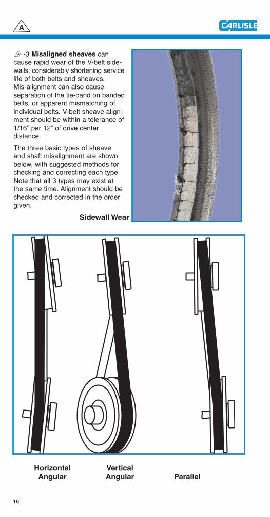
-2 Belts rubbing against the metal
guard or other obstruction will be evidenced by cut or worn fabric on theback or upper edge of the V-belt. Oftenjust replacing missing bolts in guardbrackets will remedy this situation.
A
Ruptured Cover
Fabric Worn on
Backside
16
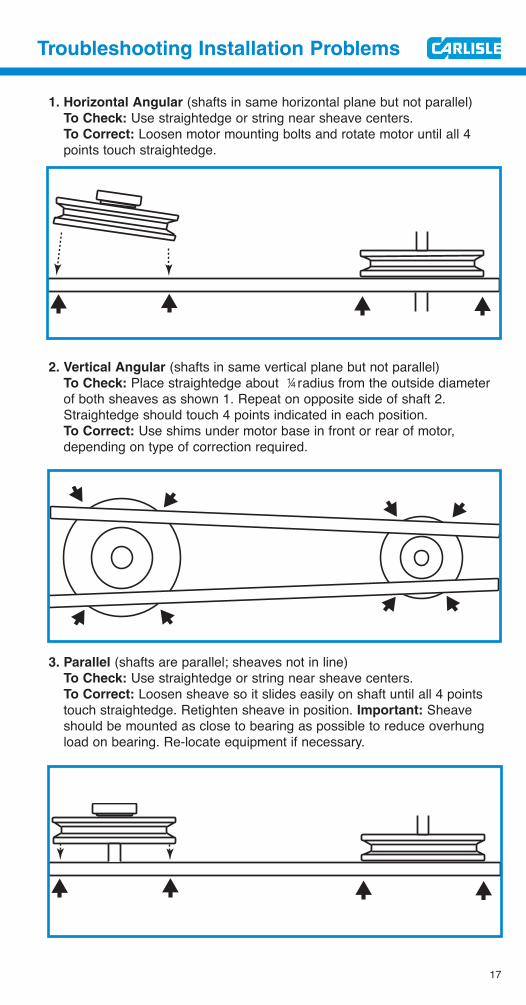
-3 Misaligned sheaves cancause rapid wear of the V-belt side-walls, considerably shortening servicelife of both belts and sheaves. Mis-alignment can also cause separation of the tie-band on bandedbelts, or apparent mismatching ofindividual belts. V-belt sheave align-ment should be within a tolerance of1/16” per 12” of drive center distance.The three basic types of sheaveand shaft misalignment are shownbelow, with suggested methods forchecking and correcting each type.Note that all 3 types may exist atthe same time. Alignment should bechecked and corrected in the ordergiven.
A
A
Sidewall Wear
Horizontal Vertical
Angular Angular Parallel
17
Troubleshooting Installation Problems
1. Horizontal Angular (shafts in same horizontal plane but not parallel)To Check: Use straightedge or string near sheave centers.To Correct: Loosen motor mounting bolts and rotate motor until all 4 points touch straightedge.
2. Vertical Angular (shafts in same vertical plane but not parallel)To Check: Place straightedge about 4 radius from the outside diameter of both sheaves as shown 1. Repeat on opposite side of shaft 2. Straightedge should touch 4 points indicated in each position.To Correct: Use shims under motor base in front or rear of motor, depending on type of correction required.
3. Parallel (shafts are parallel; sheaves not in line)To Check: Use straightedge or string near sheave centers.To Correct: Loosen sheave so it slides easily on shaft until all 4 points touch straightedge. Retighten sheave in position. Important: Sheave should be mounted as close to bearing as possible to reduce overhung load on bearing. Re-locate equipment if necessary.
18
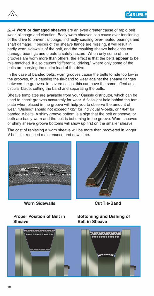
-4 Worn or damaged sheaves are an even greater cause of rapid beltwear, slippage and vibration. Badly worn sheaves can cause over-tensioningof the drive to prevent slippage, indirectly causing over-heated bearings andshaft damage. If pieces of the sheave flange are missing, it will result inbadly worn sidewalls of the belt, and the resulting sheave imbalance candamage bearings and create a safety hazard. When only some of thegrooves are worn more than others, the effect is that the belts appear to bemis-matched. It also causes “differential driving,” where only some of thebelts are carrying the entire load of the drive.In the case of banded belts, worn grooves cause the belts to ride too low inthe grooves, thus causing the tie-band to wear against the sheave flangesbetween the grooves. In severe cases, this can have the same effect as acircular blade, cutting the band and separating the belts.Sheave templates are available from your Carlisle distributor, which can beused to check grooves accurately for wear. A flashlight held behind the tem-plate when placed in the groove will help you to observe the amount ofwear. “Dishing” should not exceed 1/32” for individual V-belts, or 1/64” forbanded V-belts. A shiny groove bottom is a sign that the belt or sheave, orboth are badly worn and the belt is bottoming in the groove. Worn sheavesor shiny sheave groove bottoms will show up first on the smaller sheave.The cost of replacing a worn sheave will be more than recovered in longerV-belt life, reduced maintenance and downtime.
A
Worn Sidewalls
Proper Position of Belt in Bottoming and Dishing of
Sheave Belt in Sheave
Cut Tie-Band
A
19
Troubleshooting Installation Problems
-5 Sheaves mounted too far from the bearing cause excessive over-hung load on the bearing and overheating. This can also cause shafting towhip, bend or break. Sheaves should be mounted as close as possible tothe bearing. If this affects alignment severely, it may be necessary to re-locate the equipment to stay within alignment limits of 1/16” per 12” of shaft center-to-center distance.
-6 Bearing condition and normal wear may well be the cause of overheat-ing, rather than belt tension. They should be inspected for proper lubricationand wear according to the specifications of the bearing or equipment manu-facturer. Shaft condition should also be checked and replaced if necessary,as bent shafts can be detrimental to bearings, belts and sheaves, as well asbeing a safety hazard due to the imbalance created. Sheave “wobble” maybe caused by bent shafts.
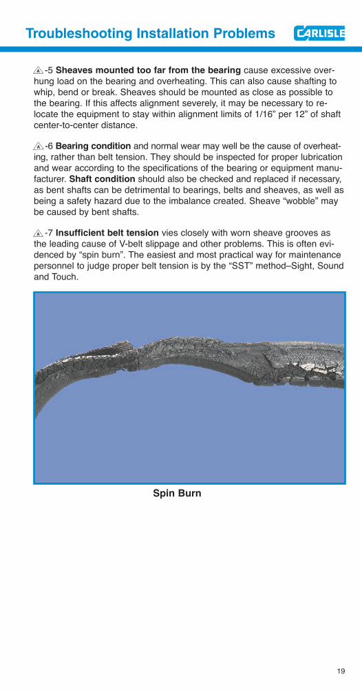
-7 Insufficient belt tension vies closely with worn sheave grooves asthe leading cause of V-belt slippage and other problems. This is often evi-denced by “spin burn”. The easiest and most practical way for maintenancepersonnel to judge proper belt tension is by the “SST” method–Sight, Soundand Touch.
A
A
A
Spin Burn
20
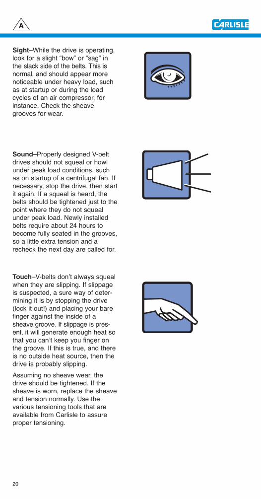
Sight–While the drive is operating,look for a slight “bow” or “sag” inthe slack side of the belts. This isnormal, and should appear morenoticeable under heavy load, suchas at startup or during the loadcycles of an air compressor, forinstance. Check the sheavegrooves for wear.
Sound–Properly designed V-beltdrives should not squeal or howlunder peak load conditions, suchas on startup of a centrifugal fan. Ifnecessary, stop the drive, then startit again. If a squeal is heard, thebelts should be tightened just to thepoint where they do not squealunder peak load. Newly installedbelts require about 24 hours tobecome fully seated in the grooves,so a little extra tension and arecheck the next day are called for.
Touch–V-belts don’t always squealwhen they are slipping. If slippageis suspected, a sure way of deter-mining it is by stopping the drive(lock it out!) and placing your barefinger against the inside of asheave groove. If slippage is pres-ent, it will generate enough heat sothat you can’t keep you finger onthe groove. If this is true, and thereis no outside heat source, then thedrive is probably slipping.Assuming no sheave wear, thedrive should be tightened. If thesheave is worn, replace the sheaveand tension normally. Use the various tensioning tools that areavailable from Carlisle to assureproper tensioning.
A
21
Troubleshooting Installation Problems
-8 Excessive tension on V-belts can be even more detrimental than toolittle tension, affecting not only the belts, but also bearings and shafts.Again, the best rule is to apply only enough tension on the belts to keepthem from slipping during startup or peak loading. Some indicators ofexcessive tensioning (but not always) are:
• Repeated belt breakage • Overheated bearings
• Excessive vibration • Whipping or bent shafts
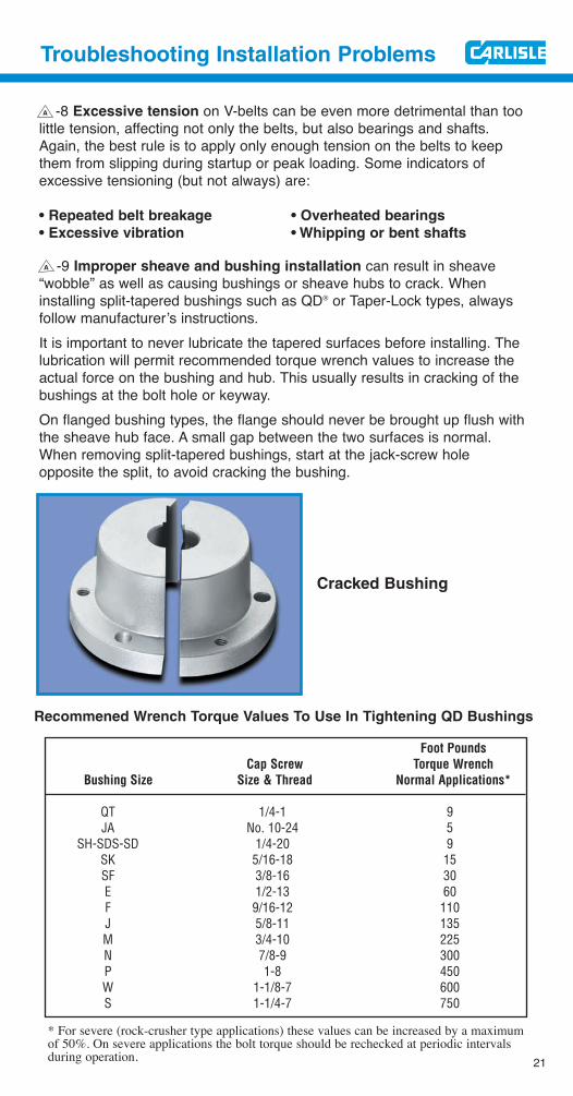
-9 Improper sheave and bushing installation can result in sheave“wobble” as well as causing bushings or sheave hubs to crack. Wheninstalling split-tapered bushings such as QD® or Taper-Lock types, alwaysfollow manufacturer’s instructions.It is important to never lubricate the tapered surfaces before installing. Thelubrication will permit recommended torque wrench values to increase theactual force on the bushing and hub. This usually results in cracking of thebushings at the bolt hole or keyway.On flanged bushing types, the flange should never be brought up flush withthe sheave hub face. A small gap between the two surfaces is normal.When removing split-tapered bushings, start at the jack-screw hole opposite the split, to avoid cracking the bushing.
A
A
Cracked Bushing
Foot PoundsCap Screw Torque Wrench
Bushing Size Size & Thread Normal Applications*
QT 1/4-1 9JA No. 10-24 5
SH-SDS-SD 1/4-20 9SK 5/16-18 15SF 3/8-16 30E 1/2-13 60F 9/16-12 110J 5/8-11 135M 3/4-10 225N 7/8-9 300P 1-8 450W 1-1/8-7 600S 1-1/4-7 750
Recommened Wrench Torque Values To Use In Tightening QD Bushings
* For severe (rock-crusher type applications) these values can be increased by a maximumof 50%. On severe applications the bolt torque should be rechecked at periodic intervalsduring operation.
22
Troubleshooting
Selection Problems
The array of V-belt types, cross-sections and lengths on the markettoday are all part of technologicalefforts to provide more efficient,cost-saving answers to your driverequirements.This category is intended to pointout how you can be sure of applyingthe best Carlisle V-belt type to yourapplications.
B
23
Troubleshooting Selection Problems
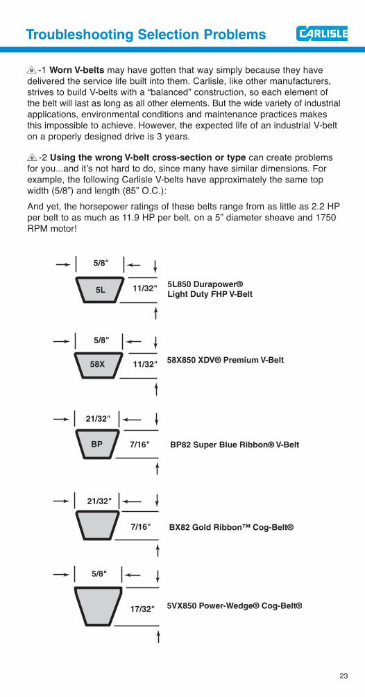
-1 Worn V-belts may have gotten that way simply because they havedelivered the service life built into them. Carlisle, like other manufacturers,strives to build V-belts with a “balanced” construction, so each element ofthe belt will last as long as all other elements. But the wide variety of industrialapplications, environmental conditions and maintenance practices makesthis impossible to achieve. However, the expected life of an industrial V-belton a properly designed drive is 3 years.
-2 Using the wrong V-belt cross-section or type can create problemsfor you...and it’s not hard to do, since many have similar dimensions. Forexample, the following Carlisle V-belts have approximately the same topwidth (5/8”) and length (85” O.C.):And yet, the horsepower ratings of these belts range from as little as 2.2 HPper belt to as much as 11.9 HP per belt. on a 5” diameter sheave and 1750RPM motor!
B
B
5/8"
5/8"
21/32"
21/32"
5/8"
11/32"
11/32"
7/16"
7/16"
17/32"
5L850 Durapower®
Light Duty FHP V-Belt
58X850 XDV® Premium V-Belt58X
5L
BP BP82 Super Blue Ribbon® V-Belt
BX82 Gold Ribbon™ Cog-Belt®
5VX850 Power-Wedge® Cog-Belt®

24
A V-belt survey of your drives by a Carlisle Certified Drive Specialist canassure you of using the correct V-belt. This service may be obtained bycontacting your Carlisle Authorized Stocking Distributor. He maintains a fulland convenient inventory of replacement belts and sheaves, and standsready to assist you in selecting the proper size and type for each application.Carlisle’s Industrial Power Transmission catalog lists all types and sizes ofstock industrial belts and sheaves. However, the following suggestions willcover the most serious selection problems:DO match the correct belt cross-section to the sheave groove. (A-A, B-B,5V-5V, etc.)DON’T use “B” section belts in “5V” grooves, or vice-versa. Check thesheave number stamped on the rim if in doubt.DON’T replace “A” or “B” heavy duty V-belts with “4L” or “5L” light duty(FHP) V-belts. FHP belts are built for Fractional Horsepower applications,and usually run singly. Most multiple drives require heavy duty belts. DO use V-belts marked “Oil and Heat Resistant” where oil or heat is present.The Carlisle Gold Ribbon™ Cog-Belt and Power-Wedge Cog-Belt offer maximum heat and oil resistance–see key numbers -2 and -3DO insist on a belt labeled “Static-dissipating” on drives operating in hazardous atmospheres.DO use banded V-belts where vibration or shock loads can cause belts toturn over or jump out of the sheave grooves.
DO use matched sets from the same manufacturer (see key number -3)DON’T mix old and new belts on a drive. They cannot be matched.
-3 Mismatched belts or mixed brands from different manufacturerscannot be matched together, and will not deliver the service life they should.Although all manufacturers use similar belt numbering systems, differentbrands with the same number will differ slightly in dimensions and are notcapable of being mixed in a set. Also, construction differences cause themto ride differently in the grooves, and to stretch differently.It should be noted that the majority of complaints regarding belt matchingare found to be due to other causes, such as misalignment and sheave wear.These factors should always be checked if belts seem to be mismatched.Carlisle belts branded with the Chek-MateTM logo do not require the use ofmatching codes, but all belts in the set must bear this symbol.
B
C C
B
GOLD RIBBON™ COG-BELT® GOLD RIBBON™ COG-BELT®
OIL HEAT RESISTANT MADE INSTATIC DISSIPATING U.S.A.OIL HEAT RESISTANT MADE INSTATIC DISSIPATING U.S.A.
BX62 BX62
B

25
Troubleshooting Selection Problems
-4 Machine-induced vibration or shock loads frequently can cause V-belts to whip or even jump off the drive, creating a safety hazard, and ofcourse, damaging the belts.On multiple-belt drives, this whipping can be reduced or eliminated by usingbanded V-belts. A banded V-belt consists of from 2 to 5 individual V-beltsjoined together with a bonded, reinforced tie-band (see illustration).These belts will ride slightly higher in the sheave grooves to provide clearancebetween the band and the sheave flange. Because of this, sheave groovesshould not be worn or “dished-out” more than 1/64”. Also, because they arebanded together, alignment of the sheaves is somewhat more critical.
B
Belts riding slightly higherin the sheave grooves.
(The chart on the next page will be helpful in selecting the best Carlislebelt for an application.)
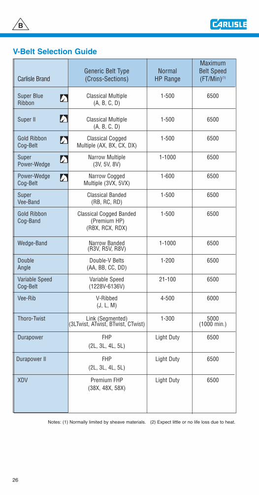
MaximumGeneric Belt Type Normal Belt Speed
Carlisle Brand (Cross-Sections) HP Range (FT/Min)(1)
Super Blue Classical Multiple 1-500 6500Ribbon (A, B, C, D)
Super ll Classical Multiple 1-500 6500(A, B, C, D)
Gold Ribbon Classical Cogged 1-500 6500Cog-Belt Multiple (AX, BX, CX, DX)
Super Narrow Multiple 1-1000 6500Power-Wedge (3V, 5V, 8V)
Power-Wedge Narrow Cogged 1-600 6500Cog-Belt Multiple (3VX, 5VX)
Super Classical Banded 1-500 6500Vee-Band (RB, RC, RD)
Gold Ribbon Classical Cogged Banded 1-500 6500Cog-Band (Premium HP)
(RBX, RCX, RDX)
Wedge-Band Narrow Banded 1-1000 6500(R3V, R5V, R8V)
Double Double-V Belts 1-200 6500Angle (AA, BB, CC, DD)
Variable Speed Variable Speed 21-100 6500Cog-Belt (1228V-6136V)
Vee-Rib V-Ribbed 4-500 6000(J, L, M)
Thoro-Twist Link (Segmented) 1-300 5000(3LTwist, ATwist, BTwist, CTwist) (1000 min.)
Durapower FHP Light Duty 6500(2L, 3L, 4L, 5L)
Durapower ll FHP Light Duty 6500(2L, 3L, 4L, 5L)
XDV Premium FHP Light Duty 6500(38X, 48X, 58X)
26
B
V-Belt Selection Guide
Notes: (1) Normally limited by sheave materials. (2) Expect little or no life loss due to heat.
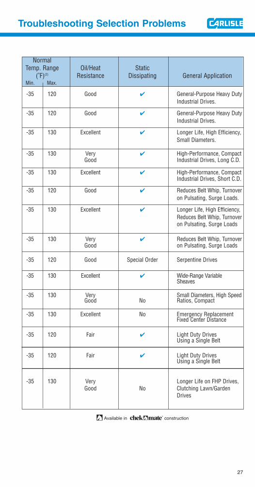
NormalTemp. Range Oil/Heat Static
(˚F)(2) Resistance Dissipating General ApplicationMin. Max.
-35 120 Good ✔ General-Purpose Heavy DutyIndustrial Drives.
-35 120 Good ✔ General-Purpose Heavy DutyIndustrial Drives.
-35 130 Excellent ✔ Longer Life, High Efficiency,Small Diameters.
-35 130 Very ✔ High-Performance, CompactGood Industrial Drives, Long C.D.
-35 130 Excellent ✔ High-Performance, CompactIndustrial Drives, Short C.D.
-35 120 Good ✔ Reduces Belt Whip, Turnoveron Pulsating, Surge Loads.
-35 130 Excellent ✔ Longer Life, High Efficiency, Reduces Belt Whip, Turnoveron Pulsating, Surge Loads
-35 130 Very ✔ Reduces Belt Whip, TurnoverGood on Pulsating, Surge Loads
-35 120 Good Special Order Serpentine Drives
-35 130 Excellent ✔ Wide-Range Variable Sheaves
-35 130 Very Small Diameters, High SpeedGood No Ratios, Compact
-35 130 Excellent No Emergency ReplacementFixed Center Distance
-35 120 Fair ✔ Light Duty DrivesUsing a Single Belt
-35 120 Fair ✔ Light Duty DrivesUsing a Single Belt
-35 130 Very Longer Life on FHP Drives, Good No Clutching Lawn/Garden
Drives
27
Troubleshooting Selection Problems
Available in construction

28
Troubleshooting
Environmental
Problems
“Environmental Protection” can beas important for a V-belt as forhumans. This section deals with theeffect of adverse environmental conditions on V-belts, and how youcan minimize these effects.
C

29
Troubleshooting Environmental Problems
-1 Improper or prolonged storage can reduce service life considerably.V-belts should be stored in a cool, dry place with no direct sunlight. On shelvesin boxes or piles, the stack should be small enough to avoid excess weightand distortion on the bottom belts. On pegs, the longer belts should be coiledin loops of suitable size to prevent distortion from the weight of the belt.The following guide provided by the RMA should be followed for optimumconditions:
Guide to Maximum Number of
Coilings of V-Belts of Storage
Belt Belt Length Number Number
Cross Section (Inches) of Coilings* of Loops*
Under 60.0 None 1A,AA,**3V 60.0 to 120.0 1 3
and B 120.0 to 180.0 2 5180.0 and up 3 7Under 75.0 None 1
BB,**C, 75.0 to 144.0 1 3and 5V 144.0 to 240.0 2 5
240.0 and up 3 7Under 120.0 None 1
120.0 to 240.0 1 3D 240.0 to 330.0 2 5
330.0 to 420.0 3 7420.0 and up 4 9Under 180.0 None 1
180.0 to 270.0 1 3E and 8V 270.0 to 390.0 2 5
390.0 to 480.0 3 7480.0 and up 4 9
*One coiling results in three loops; two coilings result in five loops, etc.**“AA” and “BB” are known as “double angle” or “hexagonal” V-belts.
The pegs should be crescent shaped in cross-section to avoid compressionset dents in the belts from sharp corners and the pegs should be sufficientlylarge in cross-section to avoid compression setting into sharp bends resultingfrom the weight of the hanging belts. It is recognized that belts are sometimes coiled in smaller loops for packagingfor shipment than indicated in the above table, but such packaging shouldnot be for prolonged storage.
C
30
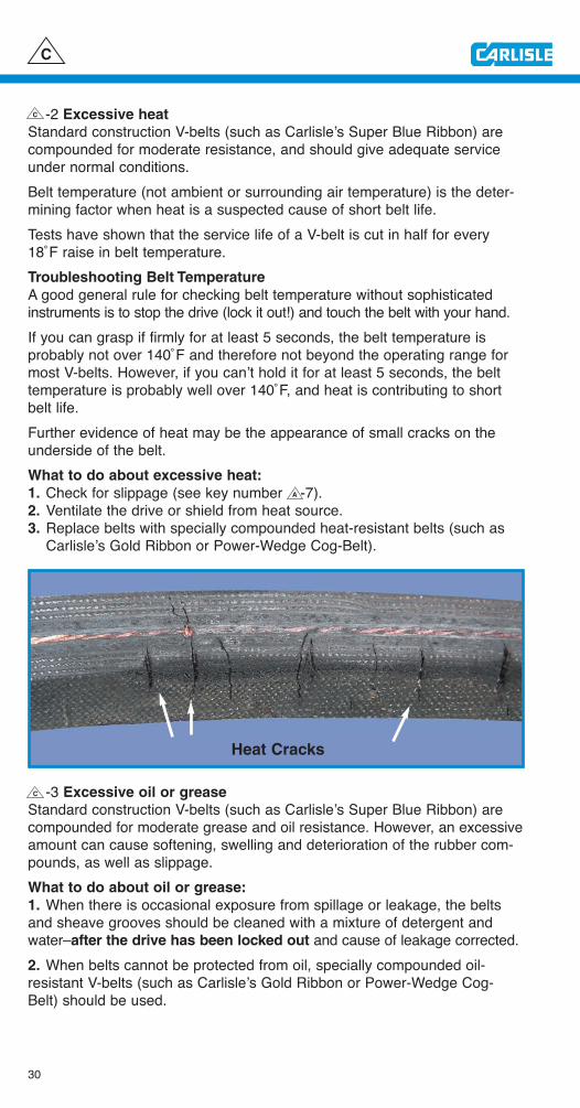
-2 Excessive heat
Standard construction V-belts (such as Carlisle’s Super Blue Ribbon) arecompounded for moderate resistance, and should give adequate serviceunder normal conditions.Belt temperature (not ambient or surrounding air temperature) is the deter-mining factor when heat is a suspected cause of short belt life.Tests have shown that the service life of a V-belt is cut in half for every18˚F raise in belt temperature.Troubleshooting Belt Temperature
A good general rule for checking belt temperature without sophisticatedinstruments is to stop the drive (lock it out!) and touch the belt with your hand.If you can grasp if firmly for at least 5 seconds, the belt temperature isprobably not over 140˚F and therefore not beyond the operating range formost V-belts. However, if you can’t hold it for at least 5 seconds, the belttemperature is probably well over 140˚F, and heat is contributing to shortbelt life.Further evidence of heat may be the appearance of small cracks on theunderside of the belt.What to do about excessive heat:
1. Check for slippage (see key number -7).2. Ventilate the drive or shield from heat source.3. Replace belts with specially compounded heat-resistant belts (such as
Carlisle’s Gold Ribbon or Power-Wedge Cog-Belt).
-3 Excessive oil or grease
Standard construction V-belts (such as Carlisle’s Super Blue Ribbon) arecompounded for moderate grease and oil resistance. However, an excessiveamount can cause softening, swelling and deterioration of the rubber com-pounds, as well as slippage.What to do about oil or grease:
1. When there is occasional exposure from spillage or leakage, the beltsand sheave grooves should be cleaned with a mixture of detergent andwater–after the drive has been locked out and cause of leakage corrected.2. When belts cannot be protected from oil, specially compounded oil-resistant V-belts (such as Carlisle’s Gold Ribbon or Power-Wedge Cog-Belt) should be used.
C
C
Heat Cracks
A
C
31
Troubleshooting Environmental Problems
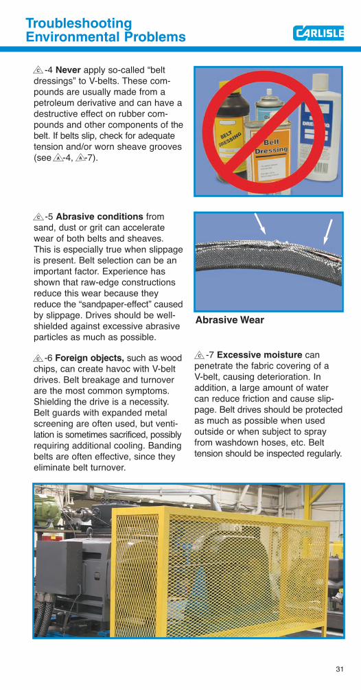
-4 Never apply so-called “beltdressings” to V-belts. These com-pounds are usually made from apetroleum derivative and can have adestructive effect on rubber com-pounds and other components of thebelt. If belts slip, check for adequatetension and/or worn sheave grooves(see -4, -7).
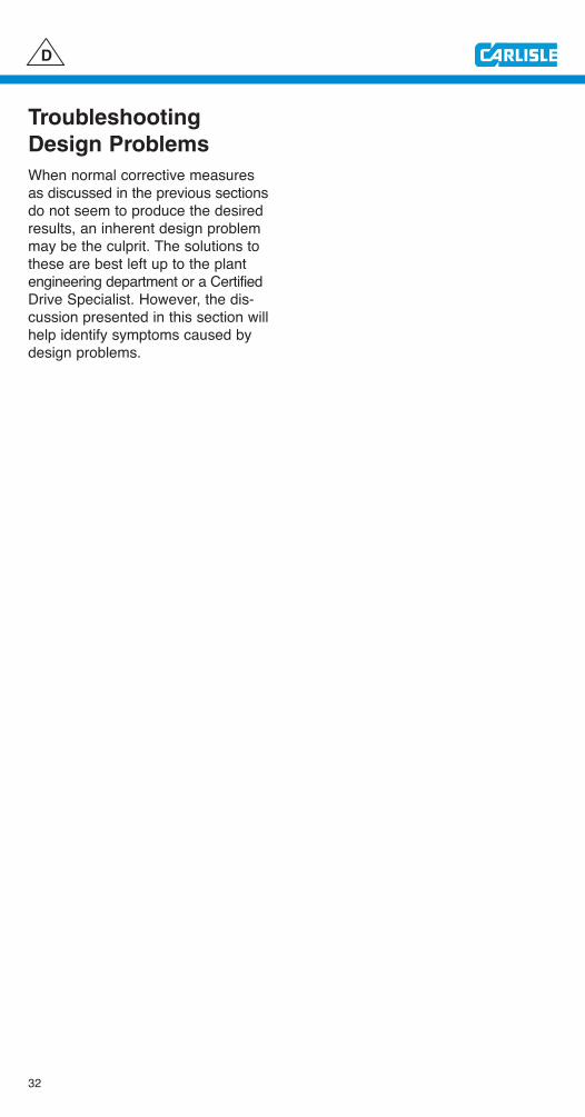
-5 Abrasive conditions fromsand, dust or grit can acceleratewear of both belts and sheaves.This is especially true when slippageis present. Belt selection can be animportant factor. Experience hasshown that raw-edge constructionsreduce this wear because theyreduce the “sandpaper-effect” causedby slippage. Drives should be well-shielded against excessive abrasiveparticles as much as possible.
-6 Foreign objects, such as woodchips, can create havoc with V-beltdrives. Belt breakage and turnoverare the most common symptoms.Shielding the drive is a necessity.Belt guards with expanded metalscreening are often used, but venti-lation is sometimes sacrificed, possiblyrequiring additional cooling. Bandingbelts are often effective, since theyeliminate belt turnover.
-7 Excessive moisture can penetrate the fabric covering of a V-belt, causing deterioration. In addition, a large amount of watercan reduce friction and cause slip-page. Belt drives should be protectedas much as possible when used outside or when subject to sprayfrom washdown hoses, etc. Belt tension should be inspected regularly.
C
A A
C
CC
Abrasive Wear
32
Troubleshooting
Design Problems
When normal corrective measuresas discussed in the previous sectionsdo not seem to produce the desiredresults, an inherent design problemmay be the culprit. The solutions tothese are best left up to the plantengineering department or a CertifiedDrive Specialist. However, the dis-cussion presented in this section willhelp identify symptoms caused bydesign problems.
D
33
Troubleshooting Design Problems
-1 Underbelting a drive, (usingfewer belts than recommended bygood design practice) results inexcessive tension in each belt onthe drive.This is commonly evidenced byexcessive stretching which requiresfrequent take-ups to prevent slippage.Another warning sign can be repeatedbelt breakage.In many cases, underbelting can becorrected simply by using raw edge,cogged V-belts which have a higherhorsepower rating. When these areused, drives should be identified toassure that future replacements aremade with this type of belt.
-2 Drive overbelting, while usuallyresulting in longer V-belt life, can bejust as serious as underbelting. Thesymptoms most commonly foundare overheated bearings and bentshafts. When too many belts are on thedrive, the total tension can beexcessive when “table” values areused. On the other hand, when toofew belts are on the drive, tensionvalues from these tables may beinadequate.
D
D
-6 Belt Vibration, is a not-so-common problem resultingfrom tension harmonics. Sinceinduced vibration can be caused byseveral factors, this should bereferred to plant engineering.
D
34
-3 When sheaves are too small for the belt cross-section, the belt flexesbeyond its normal limits. This is usually evidenced by cracks on the under-side of the belt. Table A indicates the minimum recommended sheave diameterfor flexing each belt cross-section. In most cases, use of a raw-edge coggedbelt will improve service life greatly, due to its greater flexibility.
Table A. Minimum Recommended Sheave and Idler Diameters
V-Belt Minimum P.D. Minimum O.D.Cross Section Sheave or Inside Idler Flat Backside Idler*
A, AP 3.0 4.5
B, BP 5.0 7.5
C, CP 9.0 13.5
D, DP 13.0 19.5
E, EP 21.0 31.5
AX 2.6 4.0
BX 4.0 6.0
CX 7.0 10.5
DX 11.0 16.5
3V 2.6 __
3VX 2.2 __
5V 7.0 __
5VX 4.3 __
8V 12.4 __
8VX 11.2 __
*Note: Backside Idlers are detrimental to V-belt service life.
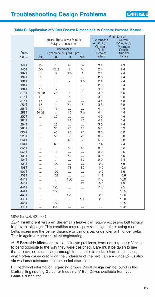
Another problem caused by sheaves that are too small is overheating ofmotor bearings, or even bent shafts. NEMA publishes minimum recommendedsheave diameters for use with electric motors to avoid excessive bearingloads. Table B shows these minimums for the most common motor types.
General purpose motors having continuous time rating with the frame sizes,horsepower and speed ratings listed in the following are designed to operatewith V-belt sheaves within the limiting dimensions listed. Selection of V-beltsheave dimensions is made by the V-belt drive vendor and the motor purchaserbut, to assure satisfactory motor operation, the selected pitch diameter shallbe no smaller than the dimensions listed on the next page.
D
D
35
Troubleshooting Design Problems
Table B. Application of V-Belt Sheave Dimensions to General Purpose Motors
143T 12 1 w 2 2.2 2.2145T 2-3 12-2 1 w 2.4 2.4182T 3 3 12 1 2.4 2.4182T 5 … … … 2.6 2.4184T … … 2 12 2.4 2.4184T 5 … … … 2.6 2.4184T 72 5 … … 3.0 3.0213T 72-10 72 3 2 3.0 3.0215T 10 … 5 3 3.0 3.0215T 15 10 … … 3.8 3.8254T 15 … 72 5 3.8 3.8254T 20 15 … … 4.4 4.4256T 20-25 … 10 72 4.4 4.4256T … 20 … … 4.6 4.4284T … … 15 10 4.6 4.4284T … 25 … … 5.0 4.4286T … 30 20 15 5.4 5.2324T … 40 25 20 6.0 6.0326T … 50 30 25 6.8 6.8364T … … 40 30 6.8 6.8364T … 60 … … 7.4 7.4365T … … 50 40 8.2 8.2365T … 75 … … 9.0 8.6404T … … 60 … 9.0 8.0404T … … … 50 9.0 8.4404T … 100 … … 10.0 8.6405T … … 75 60 10.0 10.0405T … 100 … … 10.0 8.6405T … 125 … … 11.5 10.5444T … … 100 … 11.0 10.0444T … … … 75 10.5 9.5444T … 125 … … 11.0 9.5444T … 150 … … … 10.5445T … … 125 … 12.5 12.0445T … … … 100 12.5 12.0445T … 150 … … … 10.5445T … 200 … … … 13.2
NEMA Standard, MG1-14.42
-4 Insufficient wrap on the small sheave can require excessive belt tensionto prevent slippage. This condition may require re-design, either using morebelts, increasing the center distance or using a backside idler with longer belts.This is again a matter for plant engineering.
-5 Backside idlers can create their own problems, because they cause V-beltsto bend opposite to the way they were designed. Care must be taken to seethat a backside idler is large enough in diameter to reduce harmful stresses,which often cause cracks on the underside of the belt. Table A (under -3) alsoshows these minimum recommended diameters.Full technical information regarding proper V-belt design can be found in theCarlisle Engineering Guide for Industrial V-Belt Drives available from yourCarlisle distributor.
FrameNumber
Integral-Horsepower Motors– Polyphase Indcuction
Horsepower at Synchronous Speed, Rpm
3600 1800 1200 900
V-belt SheaveConventional NarrowA,B,C,D & E 3V,5V, & 8VMinimum Minimum
Pitch OutsideDiameter, Diameter,
Inches Inches
D
D
D
36
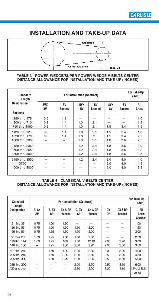
For Take-UpStandard For Installation (Subtract) (Add)Length
Designation A, AX B, BX BX & BP C, CX CX & CP DX DX & DP AllAP BP Banded CP Banded DP Banded Cross
Sections
21 thru 35 0.75 1.00 1.50 — — — — 1.0036 thru 55 0.75 1.00 1.50 1.50 2.00 — — 1.5056 thru 85 0.75 1.25 1.60 1.50 2.00 — — 2.0086 thru 112 1.00 1.25 1.60 1.50 2.00 — — 2.50116 thru 144 1.00 1.25 180 1.50 12.10 2.00 2.90 3.00148 thru 180 — 1.25 1.80 2.00 2.20 2.00 3.00 3.50191 thru 210 — 1.50 1.90 2.00 2.30 2.00 3.20 4.00225 thru 240 — 1.50 2.00 2.00 2.50 2.50 3.20 4.50225 thru 300 — 1.50 2.20 2.00 2.50 2.50 3.50 5.00315 thru 390 — — — 2.00 2.70 2.50 3.60 6.00420 and over — — — 2.50 2.90 3.00 4.10 1.5% of Belt
Length
INSTALLATION AND TAKE-UP DATA
For Take-UpStandard For Installation (Subtract) (Add)Length
Designation 3VX 3V 5VX 5V 8VX 8V All3V Banded 5V Banded 8V Banded Cross
Sections
250 thru 475 0.5 1.2 — — — — 1.0500 thru 710 0.8 1.4 1.0 2.1 — — 1.2
750 thru 1060 0.8 1.4 1.0 2.1 1.5 3.4 1.51120 thru 1250 0.8 1.4 1.0 2.1 1.5 3.4 1.81320 thru 1700 0.8 1.4 1.0 2. 1.5 3.4 2.21800 thru 2000 — — 1.0 2.1 1.8 3.6 2.52120 thru 2360 — — 1.2 2.4 1.8 3.6 3.02500 thru 2650 — — 1.2 2.4 1.8 3.6 3.22800 thru 3000 — — 1.2 2.4 1.8 3.6 3.53150 thru 3550 — — 1.2 2.4 2.0 4.0 4.0
3750 — — — — 2.0 4.0 4.54000 thru 5000 — — — — 2.0 4.0 5.5
TABLE 3 POWER-WEDGE/SUPER POWER-WEDGE V-BELTS CENTERDISTANCE ALLOWANCE FOR INSTALLATION AND TAKE-UP (INCHES)
TABLE 4 CLASSICAL V-BELTS CENTERDISTANCE ALLOWANCE FOR INSTALLATION AND TAKE-UP (INCHES)
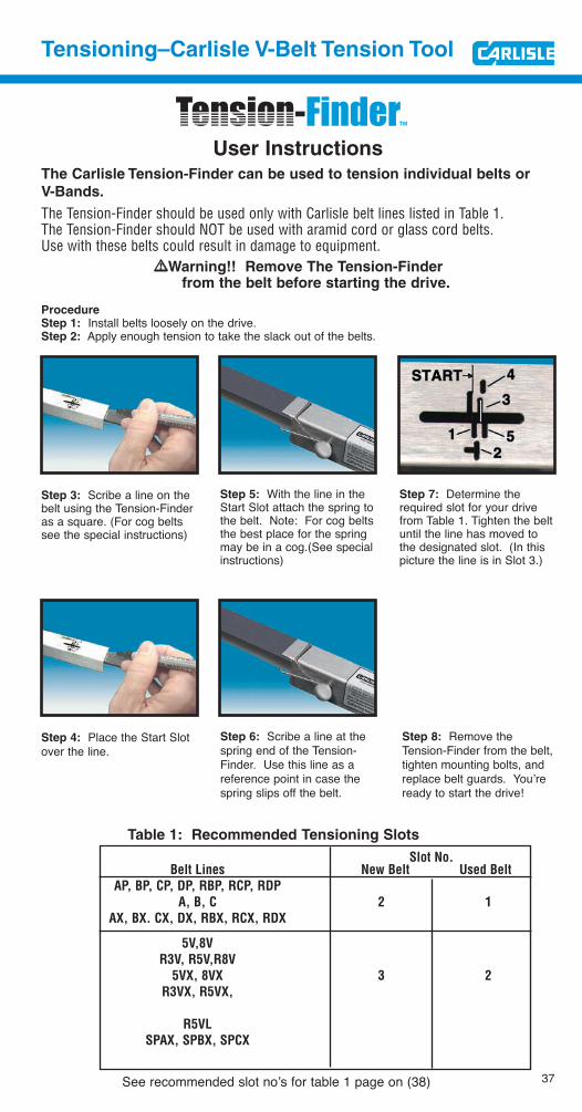
Table 1: Recommended Tensioning Slots
Slot No.Belt Lines New Belt Used Belt
AP, BP, CP, DP, RBP, RCP, RDPA, B, C 2 1
AX, BX. CX, DX, RBX, RCX, RDX
5V,8VR3V, R5V,R8V
5VX, 8VX 3 2R3VX, R5VX,
R5VLSPAX, SPBX, SPCX
37
Tensioning–Carlisle V-Belt Tension Tool
User InstructionsThe Carlisle Tension-Finder can be used to tension individual belts or
V-Bands.
The Tension-Finder should be used only with Carlisle belt lines listed in Table 1.The Tension-Finder should NOT be used with aramid cord or glass cord belts. Use with these belts could result in damage to equipment.
!!Warning!! Remove The Tension-Finder from the belt before starting the drive.
ProcedureStep 1: Install belts loosely on the drive.Step 2: Apply enough tension to take the slack out of the belts.
Step 3: Scribe a line on thebelt using the Tension-Finderas a square. (For cog beltssee the special instructions)
Step 5: With the line in theStart Slot attach the spring tothe belt. Note: For cog beltsthe best place for the springmay be in a cog.(See specialinstructions)
Step 7: Determine therequired slot for your drivefrom Table 1. Tighten the beltuntil the line has moved tothe designated slot. (In this picture the line is in Slot 3.)
Step 4: Place the Start Slotover the line.
Step 6: Scribe a line at thespring end of the Tension-Finder. Use this line as areference point in case thespring slips off the belt.
Step 8: Remove theTension-Finder from the belt,tighten mounting bolts, andreplace belt guards. You’reready to start the drive!
See recommended slot no’s for table 1 page on (38)
38
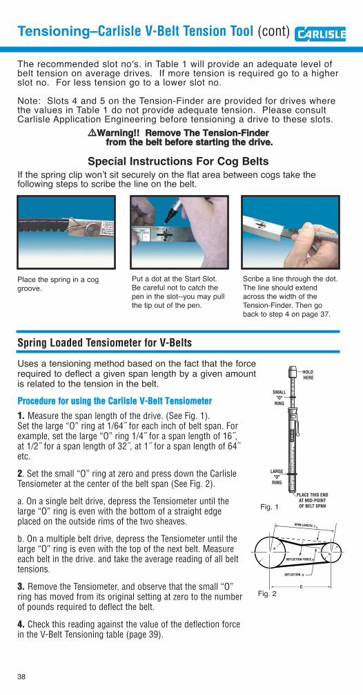
Tensioning–Carlisle V-Belt Tension Tool (cont)
The recommended slot no's. in Table 1 will provide an adequate level ofbelt tension on average drives. If more tension is required go to a higherslot no. For less tension go to a lower slot no.
Note: Slots 4 and 5 on the Tension-Finder are provided for drives wherethe values in Table 1 do not provide adequate tension. Please consultCarlisle Application Engineering before tensioning a drive to these slots.
!!WWaarrnniinngg!!!! RReemmoovvee TThhee TTeennssiioonn--FFiinnddeerr ffrroomm tthhee bbeelltt bbeeffoorree ssttaarrttiinngg tthhee ddrriivvee..
Special Instructions For Cog Belts
If the spring clip won’t sit securely on the flat area between cogs take the following steps to scribe the line on the belt.
Place the spring in a coggroove.
Put a dot at the Start Slot.Be careful not to catch thepen in the slot--you may pullthe tip out of the pen.
Scribe a line through the dot.The line should extendacross the width of theTension-Finder. Then goback to step 4 on page 37.
Spring Loaded Tensiometer for V-Belts
Uses a tensioning method based on the fact that the forcerequired to deflect a given span length by a given amountis related to the tension in the belt.
510
1520
2530
LBDE
L.DE
L.1
INCH
ESIN
CHES
25
1015
2025
30LB
SMALL"O"
RING
LARGE"O"
RING
PLACE THIS ENDAT MID-POINTOF BELT SPAN
HOLD HERE
DEL.
1IN
CHES
2
PPrroocceedduurree ffoorr uussiinngg tthhee CCaarrlliissllee VV--BBeelltt TTeennssiioommeetteerr
11.. Measure the span length of the drive. (See Fig. 1).Set the large “O” ring at 1/64˝ for each inch of belt span. Forexample, set the large “O” ring 1/4˝ for a span length of 16˝,at 1/2˝ for a span length of 32˝, at 1˝ for a span length of 64˝etc.
22. Set the small “O” ring at zero and press down the CarlisleTensiometer at the center of the belt span (See Fig. 2).
a. On a single belt drive, depress the Tensiometer until thelarge “O” ring is even with the bottom of a straight edgeplaced on the outside rims of the two sheaves.
b. On a multiple belt drive, depress the Tensiometer until thelarge “O” ring is even with the top of the next belt. Measureeach belt in the drive. and take the average reading of all belttensions.
33.. Remove the Tensiometer, and observe that the small “O”ring has moved from its original setting at zero to the numberof pounds required to deflect the belt.
44.. Check this reading against the value of the deflection forcein the V-Belt Tensioning table (page 39).
SPAN LENGTH, L
C
S
DEFLECTION FORCE,p
DEFLECTION, q
D
d
Fig. 1
Fig. 2
Tensioning
39
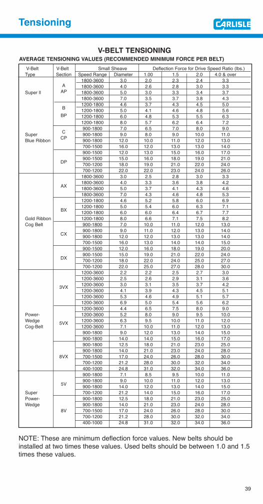
V-BELT TENSIONINGAVERAGE TENSIONING VALUES (RECOMMENDED MINIMUM FORCE PER BELT)
V-Belt V-Belt Small Sheave Deflection Force for Drive Speed Ratio (lbs.)Type Section Speed Range Diameter 1.00 1.5 2.0 4.0 & over
1800-3600 3.0 2.0 2.3 2.4 3.3A 1800-3600 4.0 2.6 2.8 3.0 3.3
Super ll AP 1800-3600 5.0 3.0 3.3 3.4 3.71800-3600 7.0 3.5 3.7 3.8 4.31200-1800 4.6 3.7 4.3 4.5 5.0
B 1200-1800 5.0 4.1 4.6 4.8 5.6BP 1200-1800 6.0 4.8 5.3 5.5 6.3
1200-1800 8.0 5.7 6.2 6.4 7.2900-1800 7.0 6.5 7.0 8.0 9.0
Super C 900-1800 9.0 8.0 9.0 10.0 11.0Blue Ribbon CP 900-1800 12.0 10.0 11.0 12.0 13.0
700-1500 16.0 12.0 13.0 13.0 14.0900-1500 12.0 13.0 15.0 16.0 17.0900-1500 15.0 16.0 18.0 19.0 21.0
DP 700-1200 18.0 19.0 21.0 22.0 24.0700-1200 22.0 22.0 23.0 24.0 26.01800-3600 3.0 2.5 2.8 3.0 3.31800-3600 4.0 3.3 3.6 3.8 4.2
AX 1800-3600 5.0 3.7 4.1 4.3 4.61800-3600 7.0 4.3 4.6 4.8 5.31200-1800 4.6 5.2 5.8 6.0 6.91200-1800 5.0 5.4 6.0 6.3 7.1
BX 1200-1800 6.0 6.0 6.4 6.7 7.7Gold Ribbon 1200-1800 8.0 6.6 7.1 7.5 8.2Cog Belt 900-1800 7.0 10.0 11.0 12.0 13.0
900-1800 9.0 11.0 12.0 13.0 14.0CX 900-1800 12.0 12.0 13.0 13.0 14.0
700-1500 16.0 13.0 14.0 14.0 15.0900-1500 12.0 16.0 18.0 19.0 20.0900-1500 15.0 19.0 21.0 22.0 24.0
DX 700-1200 18.0 22.0 24.0 25.0 27.0700-1200 22.0 25.0 27.0 28.0 30.01200-3600 2.2 2.2 2.5 2.7 3.01200-3600 2.5 2.6 2.9 3.1 3.6
3VX 1200-3600 3.0 3.1 3.5 3.7 4.21200-3600 4.1 3.9 4.3 4.5 5.11200-3600 5.3 4.6 4.9 5.1 5.71200-3600 6.9 5.0 5.4 5.6 6.21200-3600 4.4 6.5 7.5 8.0 9.0
Power- 1200-3600 5.2 8.0 9.0 9.5 10.0Wedge 5VX 1200-3600 6.3 9.5 10.0 11.0 12.0Cog-Belt 1200-3600 7.1 10.0 11.0 12.0 13.0
900-1800 9.0 12.0 13.0 14.0 15.0900-1800 14.0 14.0 15.0 16.0 17.0900-1800 12.5 18.0 21.0 23.0 25.0900-1800 14.0 21.0 23.0 24.0 28.0
8VX 700-1500 17.0 24.0 26.0 28.0 30.0700-1200 21.2 28.0 30.0 32.0 34.0400-1000 24.8 31.0 32.0 34.0 36.0900-1800 7.1 8.5 9.5 10.0 11.0900-1800 9.0 10.0 11.0 12.0 13.0
5V 900-1800 14.0 12.0 13.0 14.0 15.0Super 700-1200 21.2 14.0 15.0 16.0 17.0Power- 900-1800 12.5 18.0 21.0 23.0 25.0Wedge 900-1800 14.0 21.0 23.0 24.0 28.0
8V 700-1500 17.0 24.0 26.0 28.0 30.0700-1200 21.2 28.0 30.0 32.0 34.0400-1000 24.8 31.0 32.0 34.0 36.0
NOTE: These are minimum deflection force values. New belts should beinstalled at two times these values. Used belts should be between 1.0 and 1.5times these values.
40
Topical Index
Topic PagesABRASION ......................................................31ALIGNMENT, Sheaves ..............................6,8,16
BANDED BELTS................................24,25,26,31BEARINGS, Overheated ..............18,19,21,33,34BUSHINGS, Installation of ..............................21
CHECKLIST, Belt Installation ............................9CHEK-MATE ..........................................24,26,27COGGED V-BELTS ............2,23,24,226,30,33,34COILING of BELTS ..........................................29COMPRESSION SECTION of V-BELTS ..............2CORD, Tensile ..............................................2,15
DESIGN, Drive Problems ............12,32,33,34,35DISHING, Sheave Groove (see SHEAVE Wear)DRESSING, Belt ..............................................31
EFFICIENCY ......................................................3ELEMENTS OF BELT CONSTRUCTION ..............2ENERGY (see EFFICIENCY)ENVIRONMENTAL CONDITIONS
• Abrasion ................................................31• Foreign objects in drive ..........................31• Heat..............................................24,27,30• Moisture ................................................31• Oil & grease ......................................27,30• Storage ..................................................29
GROOVE, Inspection of ..................5,6,18,24,25GUARDS, Drive ....................................15,30,31
HEAT, Effect and Measurement of• Ambient ..................................12,24,27,30• Bearing ..............................12,18,19,34,35• Belt ....................................................27,30• Sheave....................................................20
IDLERS, Backside ..........................................35IMPULSE LOADS ............................................25INSPECTION
• Bearing ..................................................19• Belt ....................................................12,20• Shaft ................................................5,6,17• Sheave ................................5,6,8,16,18,19
INSTALLATION• Belt ................................4,7,9,15,36,37,38• Bushing ..................................................21• Sheave....................................6,8,16,19,21• Tension....................5,9,18,19,33,37,38,39• Take-Up data ..........................................36
INSUFFICIENT WRAP......................................35
MATCHING, Belt ..........................................7,24MISALIGNMENT, Sheave ................6,8,16,17,19MISMATCHING, Apparent ....................16,18,24MISPLACED SLACK ........................................15MIXED BRANDS, Use of ..............................7,24MOISTURE, Excessive ....................................31MOUNTING, Sheave........................6,8,16,19,21
NEMA, Sheave Standards ..............................35
OIL and GREASE ............................................30OVERBELTED DRIVE ......................................33OVERHUNG LOAD ................................19,34,35OVERLOADED DRIVE......................................33OVER-TENSIONING ..............................21,33,35
Topic PagesPITCH DIAMETER ......................................34,35PRYING BELTS ON DRIVE ..........................7,15
RAW EDGE BELTS (see COGGED V-BELTS)REPLACEMENT CHECKLIST..............................9RE-TENSIONING ..........................................8,20
SAFETY ................................................3,5,20,30SEATING, V-belt ......................................8,20,24SELECTION, V-belt ..........................................23SHEAVE
• Alignment ........................................6,8,16• Bushing ..................................................21• Cleaning ..................................................5• Damage ....................................6,18,21,32• Diameters ..........................................34,35• Inspection ..............................5,6,16,18,25• Installation ..................................6,8,16,19• Wear ..............................................6,18,25• Wrap ......................................................35
SHIELDS, Drive ....................................15,30,31SHOCK LOADS ..........................................15,25SIDEWALLS
• Belt ......................................................2,31• Sheave............................................6,18,31
SIGHT METHOD, Tensioning ..........................20SLIPPAGE, Causes ............12,18,19,20,30,31,35SOUND METHOD, Tensioning ........................20SPLIT-TAPER BUSHINGS................................21SQUEAL ....................................................12,20STATIC DISSIPATION ................................24,27STORAGE........................................................29STRETCH ..................................................24,33
TAKE-UP (see TENSION)TEMPERATURE
• Ambient........................................24,27,30• Belt ..............................................24,27,30• Sheave....................................................20
TEMPLATE, Sheave ........................................18TENSILE CORDS ..........................................2,15TENSIOMETER................................................38TENSION
• Belt ..............8,19,20,21,31,33,35,37,38,39• Tension-Finder ..................................37,38
TIE-BAND ........................................15,17,25,31TORQUE WRENCH, Use of..............................21TOUCH METHOD, to Determine:
• Belt Temperature ....................................30• Slippage ................................................20• Tension................................................8,20
TROUBLESHOOTING GUIDE ......................12,13TURNOVER, Belt ..................................15,25,31
UNDERBELTED DRIVE ....................................33
VIBRATION, V-belt ..................3,12,18,21,25,33
V-Belt Tensioning tools ..............................37-38
WOBBLE, Sheave ........................................6,21WRAP, Insufficient ..........................................35
Thoro-Twist® V-Belting (3L,A,B,C,)For use as an emergency replacement where endless V-belts cannot be installed.
QD Bushings
Standardized for interchangeability. Tapered and fully split through bore length for equivalent of interference fit.
Power-Wedge® QD Sheaves (3V,5V,8V) High -capacity cast iron sheaves for use with narrow V-Belts. Standardized QD bushings.
V-Ribbed Sheaves (J)For use with V-ribbed belts. Precision form-cut grooves for smooth running.
Classical QD Sheaves (AQ,BQ,CQ,DQ)High-Quality heavy duty sheaves for classical (A,B,C,D) V-Belts.
Durapower Sheaves-Bushed Type (3L-4L,4L-5L)Cast iron, for all types of light-duty and FHP applications using 3L,4L,5L, A and B V-Belts. Bushing interchanges with similar competitive types.
Durapower Sheaves - Fixed Bore Type (3L-4L,4L-5L)Cast iron, bore and keywayed to fit popular shaft sizes. For light-duty.
Durapower Sheaves - Adjustable Diameter (3L-4L,4L-5L)Rugged cast iron, two piece threaded assembly allows adjustment of pitch diameter. Combination grooves for use with 3L,4L,5L,A and B section V-Belts.
RPP® PANTHER (8M,14M)The ultimate choice in high torque synchronous belt drives.
RPP® PANTHER Sprockets
Specially designed to handle the high torque transmitted by PANTHER belt drives.
RPP PLUS® (3M, 5M, 8M,14M, 20M)Up to 50% more power capacity than conventional high torque drives.
Dual RPP® (D8M,D14M)Dual sided synchronous belt with deep tooth parabolic profile teeth allowing synchronous transmission via both the external and internal pulleys in a multi-pulley drive.
RPP® Sprockets (5M,8M,14M,20M)Precision companion to RPP and RPP PLUS belts on high torque synchronous drives.
Synchro-Cog® Timing Belt (XL,L,H,XH,XXH)For synchronization of driven speed to driver speed.
Synchro-Cog® Dual Timing Belt (DXL, DL, DH) Provides maintenance-free synchronization from both sides of the belt on positive drive applications. Excellent performance on serpentine type drives.
Synchro-Cog® Timing Pulleys
(XL,L,H,XH,XXH) For perfect mating withtiming belts on synchronous drives.
16
17
18
19
20
21
22
23
24
25
26
27
28
29
30
31
*Power-Wedge® Cog-Belt® (3VX,5VX,8VX) Space saving V-Belt transmits higher HP and gives longer life for maximum savings.
*Super Power-Wedge® V-Belt (3V, 5V,8V)Designed for lower cost, more compact multiple-belt drives.
Wedge-Band® (R3V,R5V,R8V,R3VX,R5VX,R8VX)Carlisle's Power-Wedge belt in banded design. Eliminates whip and turnover on narrow drives.
Wedge-Band® Chipper Drive Belt (R5VL) Specially designed and constructed to meet the unique demands of the forest products industry. Ideally suited for chipper saws,debarker drives, head rigs and hogs.
Variable Speed Cog-Belt® (1228V through 6136V Series)Carlisle Variable Speed Cog-Belt offers the same high standard of quality in a replacement belt that Carlisle provides to the OEM.
*Super Blue Ribbon® V-Belt (AP,BP,CP,DP) The finest wrapped belt in the industry.
*Super II® V- Belt (A,B,C)The revolutionary raw-edge® belt from Carlisle that blows the cover off conventional wrapped belts due to its unique construction.
Super Vee-Band ® (RBP,RCP,RDP) Carlisle’s Super Blue Ribbon V-Belt in banded design. Eliminates belt whip and turnover on conventional drives.
Gold Ribbon™ Cog-Belt® (AX,BX,CX,DX)The Energy Saver! More efficientthan ordinary belts. The finest classical V-belt available.
Gold Ribbon™ Cog-Band® (RBX,RCX,RDX)A unique combination of our energy saving Cog-Belt and the banded concept.
Double-Angle Belt (AA,BB,CC)Designed for use on serpentine type drive applications.
Vee-Ribbed™ Belt (J,L,M)Increased HP in 2/3 the space required for normal belts.
Durapower® Light duty V-Belt (3L,4L,5L) Carlisle wrapped belt technology makesDurapower a real heavyweight in thelight duty v-belt arena.
Durapower® ll (Raw Edge)
FHP Light Duty V-Belt
Longer belt life and improved performance.
XDV® Xtra Duty V-Belt (38X,48X,58X)The XDV belt is designed for tough belt drives; typical of snowblowers, lawn mowers, garden tractors, tillers, etc. Cover fabric design is geared to optimize declutching capability for smooth and reliable transfer of power.
* available in construction
Carlisle’s Full Power Transmission Line
1
2
3
4
5
6
7
8
9
10
11
12
13
14
15
12
3
6
4
5
8
7
Carlisle’s Full Power Transmission Line (Cont.)
16
18
17
19
21
23
24
22
26
31
20
25
28
9
11
10
12
27
29
30
14
13
15
Power Transmission Products, Inc.
Service Manualfor
Industrial V-Belt Drives
Service Manualfor
Industrial V-Belt Drives
Power Transmission Products, Inc.
102163 (Rev ©2007) Carlisle Power Transmission Products, Inc.
U.S.A.
Customer Service: (866) 773-2926
CANADA
Customer Service: (866) 797-2358
www.cptbelts.com
U.S.A.
Customer Service: (866) 773-2926
CANADA
Customer Service: (866) 797-2358
www.carlislebelts.com