Embed Size (px)
Citation preview
Product Manual
Serial Attached SCSI (SAS)
100293071Rev. CDecember 2009
Interface Manual
Print Date:2010-Jan-13 11:56:37 CST Released; Prod Rel; C; 100293071 Seagate Confidential

©2004-2006, 2009, Seagate Technology LLC All rights reserved. Publication number: 100293071, Rev. C December 2009Seagate, Seagate Technology and the Wave logo are registered trademarks of Seagate Technology LLC in the United States and/or other countries. All other trademarks or registered trademarks are the prop-erty of their respective owners. Seagate reserves the right to change, without notice, product offerings or specifications. No part of this publication may be reproduced in any form without the written permission of Seagate Technology LLC.
Print Date:2010-Jan-13 11:56:37 CST Released; Prod Rel; C; 100293071 Seagate Confidential
Serial Attached SCSI (SAS) Interface Manual, Rev. C i
Table of Contents1.0 Interface requirements. . . . . . . . . . . . . . . . . . . . . . . . . . . . . . . . . . . . . . . . . . . . . . . . . . . . . . . . . . . 1
1.1 Acknowledgements . . . . . . . . . . . . . . . . . . . . . . . . . . . . . . . . . . . . . . . . . . . . . . . . . . . . . . . . 11.2 How to use this interface manual . . . . . . . . . . . . . . . . . . . . . . . . . . . . . . . . . . . . . . . . . . . . . 1
1.2.1 Scope. . . . . . . . . . . . . . . . . . . . . . . . . . . . . . . . . . . . . . . . . . . . . . . . . . . . . . . . . . . 21.2.2 Applicable specifications . . . . . . . . . . . . . . . . . . . . . . . . . . . . . . . . . . . . . . . . . . . . 31.2.3 Other references . . . . . . . . . . . . . . . . . . . . . . . . . . . . . . . . . . . . . . . . . . . . . . . . . . 3
1.3 General interface description. . . . . . . . . . . . . . . . . . . . . . . . . . . . . . . . . . . . . . . . . . . . . . . . . 41.3.1 Introduction to Serial Attached SCSI Interface (SAS) . . . . . . . . . . . . . . . . . . . . . . 41.3.2 The SAS interface . . . . . . . . . . . . . . . . . . . . . . . . . . . . . . . . . . . . . . . . . . . . . . . . . 41.3.3 Glossary . . . . . . . . . . . . . . . . . . . . . . . . . . . . . . . . . . . . . . . . . . . . . . . . . . . . . . . . . 61.3.4 Keywords . . . . . . . . . . . . . . . . . . . . . . . . . . . . . . . . . . . . . . . . . . . . . . . . . . . . . . . 16
1.4 Physical interface characteristics. . . . . . . . . . . . . . . . . . . . . . . . . . . . . . . . . . . . . . . . . . . . . 181.5 Bit and byte ordering . . . . . . . . . . . . . . . . . . . . . . . . . . . . . . . . . . . . . . . . . . . . . . . . . . . . . . 18
2.0 General . . . . . . . . . . . . . . . . . . . . . . . . . . . . . . . . . . . . . . . . . . . . . . . . . . . . . . . . . . . . . . . . . . . . . . 192.1 Architecture . . . . . . . . . . . . . . . . . . . . . . . . . . . . . . . . . . . . . . . . . . . . . . . . . . . . . . . . . . . . . 19
2.1.1 Architecture overview. . . . . . . . . . . . . . . . . . . . . . . . . . . . . . . . . . . . . . . . . . . . . . 192.1.2 Physical links and phys . . . . . . . . . . . . . . . . . . . . . . . . . . . . . . . . . . . . . . . . . . . . 192.1.3 Logical links . . . . . . . . . . . . . . . . . . . . . . . . . . . . . . . . . . . . . . . . . . . . . . . . . . . . . 212.1.4 Ports (narrow ports and wide ports) . . . . . . . . . . . . . . . . . . . . . . . . . . . . . . . . . . . 212.1.5 SAS devices. . . . . . . . . . . . . . . . . . . . . . . . . . . . . . . . . . . . . . . . . . . . . . . . . . . . . 232.1.6 Expander devices. . . . . . . . . . . . . . . . . . . . . . . . . . . . . . . . . . . . . . . . . . . . . . . . . 242.1.7 Service delivery subsystem . . . . . . . . . . . . . . . . . . . . . . . . . . . . . . . . . . . . . . . . . 252.1.8 Domains . . . . . . . . . . . . . . . . . . . . . . . . . . . . . . . . . . . . . . . . . . . . . . . . . . . . . . . . 252.1.9 Expander device topologies . . . . . . . . . . . . . . . . . . . . . . . . . . . . . . . . . . . . . . . . . 262.1.10 Pathways . . . . . . . . . . . . . . . . . . . . . . . . . . . . . . . . . . . . . . . . . . . . . . . . . . . . . . . 282.1.11 Connections . . . . . . . . . . . . . . . . . . . . . . . . . . . . . . . . . . . . . . . . . . . . . . . . . . . . . 28
2.2 Names and identifiers . . . . . . . . . . . . . . . . . . . . . . . . . . . . . . . . . . . . . . . . . . . . . . . . . . . . . 312.2.1 Names and identifiers . . . . . . . . . . . . . . . . . . . . . . . . . . . . . . . . . . . . . . . . . . . . . 312.2.2 SAS addresses . . . . . . . . . . . . . . . . . . . . . . . . . . . . . . . . . . . . . . . . . . . . . . . . . . 312.2.3 Hashed SAS address. . . . . . . . . . . . . . . . . . . . . . . . . . . . . . . . . . . . . . . . . . . . . . 322.2.4 Device names . . . . . . . . . . . . . . . . . . . . . . . . . . . . . . . . . . . . . . . . . . . . . . . . . . . 322.2.5 Port identifiers . . . . . . . . . . . . . . . . . . . . . . . . . . . . . . . . . . . . . . . . . . . . . . . . . . . 322.2.6 Phy identifiers. . . . . . . . . . . . . . . . . . . . . . . . . . . . . . . . . . . . . . . . . . . . . . . . . . . . 32
2.3 Resets . . . . . . . . . . . . . . . . . . . . . . . . . . . . . . . . . . . . . . . . . . . . . . . . . . . . . . . . . . . . . . . . . 332.3.1 Reset overview. . . . . . . . . . . . . . . . . . . . . . . . . . . . . . . . . . . . . . . . . . . . . . . . . . . 332.3.2 Hard reset . . . . . . . . . . . . . . . . . . . . . . . . . . . . . . . . . . . . . . . . . . . . . . . . . . . . . . 33
2.4 I_T nexus loss . . . . . . . . . . . . . . . . . . . . . . . . . . . . . . . . . . . . . . . . . . . . . . . . . . . . . . . . . . . 342.5 Phy power conditions . . . . . . . . . . . . . . . . . . . . . . . . . . . . . . . . . . . . . . . . . . . . . . . . . . . . . 35
2.5.1 Low phy power conditions . . . . . . . . . . . . . . . . . . . . . . . . . . . . . . . . . . . . . . . . . . 352.5.2 SCSI phy power conditions . . . . . . . . . . . . . . . . . . . . . . . . . . . . . . . . . . . . . . . . . 362.5.3 SATA phy power conditions . . . . . . . . . . . . . . . . . . . . . . . . . . . . . . . . . . . . . . . . . 36
2.6 Phy test functions . . . . . . . . . . . . . . . . . . . . . . . . . . . . . . . . . . . . . . . . . . . . . . . . . . . . . . . . 372.6.1 Phy test functions overview . . . . . . . . . . . . . . . . . . . . . . . . . . . . . . . . . . . . . . . . . 372.6.2 Transmit pattern phy test function . . . . . . . . . . . . . . . . . . . . . . . . . . . . . . . . . . . . 37
2.7 Phy events. . . . . . . . . . . . . . . . . . . . . . . . . . . . . . . . . . . . . . . . . . . . . . . . . . . . . . . . . . . . . . 38
3.0 Physical layer . . . . . . . . . . . . . . . . . . . . . . . . . . . . . . . . . . . . . . . . . . . . . . . . . . . . . . . . . . . . . . . . . 443.1 Physical layer overview . . . . . . . . . . . . . . . . . . . . . . . . . . . . . . . . . . . . . . . . . . . . . . . . . . . . 443.2 Conventions for defining maximum limits for S-parameters . . . . . . . . . . . . . . . . . . . . . . . . 443.3 Compliance points . . . . . . . . . . . . . . . . . . . . . . . . . . . . . . . . . . . . . . . . . . . . . . . . . . . . . . . . 463.4 TxRx connection characteristics . . . . . . . . . . . . . . . . . . . . . . . . . . . . . . . . . . . . . . . . . . . . . 47
3.4.1 TxRx connection characteristics overview . . . . . . . . . . . . . . . . . . . . . . . . . . . . . . 473.4.2 TxRx connection general characteristics . . . . . . . . . . . . . . . . . . . . . . . . . . . . . . . 48
Print Date:2010-Jan-13 11:56:37 CST Released; Prod Rel; C; 100293071 Seagate Confidential
ii Serial Attached SCSI (SAS) Interface Manual, Rev. C
3.4.3 TxRx connection S-parameter limits. . . . . . . . . . . . . . . . . . . . . . . . . . . . . . . . . . . 493.4.4 TxRx connection characteristics for untrained 1.5 Gbps and 3 Gbps . . . . . . . . . 51
3.5 Test loads. . . . . . . . . . . . . . . . . . . . . . . . . . . . . . . . . . . . . . . . . . . . . . . . . . . . . . . . . . . . . . . 523.5.1 Test loads overview . . . . . . . . . . . . . . . . . . . . . . . . . . . . . . . . . . . . . . . . . . . . . . . 523.5.2 Zero-length test load. . . . . . . . . . . . . . . . . . . . . . . . . . . . . . . . . . . . . . . . . . . . . . . 523.5.3 TCTF test load . . . . . . . . . . . . . . . . . . . . . . . . . . . . . . . . . . . . . . . . . . . . . . . . . . . 543.5.4 Low-loss TCTF test load. . . . . . . . . . . . . . . . . . . . . . . . . . . . . . . . . . . . . . . . . . . . 583.5.5 Reference transmitter test load . . . . . . . . . . . . . . . . . . . . . . . . . . . . . . . . . . . . . . 60
3.6 Transmitter device and receiver device electrical characteristics . . . . . . . . . . . . . . . . . . . . 633.6.1 General electrical characteristics . . . . . . . . . . . . . . . . . . . . . . . . . . . . . . . . . . . . . 633.6.2 Transmitter device and receiver device transients . . . . . . . . . . . . . . . . . . . . . . . . 633.6.3 Eye masks and the jitter transfer function (JTF). . . . . . . . . . . . . . . . . . . . . . . . . . 643.6.4 Transmitter device characteristics . . . . . . . . . . . . . . . . . . . . . . . . . . . . . . . . . . . . 673.6.5 Receiver device characteristics . . . . . . . . . . . . . . . . . . . . . . . . . . . . . . . . . . . . . . 783.6.6 Spread spectrum clocking (SSC) . . . . . . . . . . . . . . . . . . . . . . . . . . . . . . . . . . . . . 943.6.7 Non-tracking clock architecture . . . . . . . . . . . . . . . . . . . . . . . . . . . . . . . . . . . . . . 98
4.0 Phy layer . . . . . . . . . . . . . . . . . . . . . . . . . . . . . . . . . . . . . . . . . . . . . . . . . . . . . . . . . . . . . . . . . . . 994.1 Phy layer overview . . . . . . . . . . . . . . . . . . . . . . . . . . . . . . . . . . . . . . . . . . . . . . . . . . . . . . . . 994.2 Encoding (8b10b). . . . . . . . . . . . . . . . . . . . . . . . . . . . . . . . . . . . . . . . . . . . . . . . . . . . . . . . . 99
4.2.1 8b10b Encoding overview . . . . . . . . . . . . . . . . . . . . . . . . . . . . . . . . . . . . . . . . . . 994.2.2 8b10b coding notation conventions . . . . . . . . . . . . . . . . . . . . . . . . . . . . . . . . . . . 99
4.3 Character encoding and decoding . . . . . . . . . . . . . . . . . . . . . . . . . . . . . . . . . . . . . . . . . . . 1014.3.1 Introduction. . . . . . . . . . . . . . . . . . . . . . . . . . . . . . . . . . . . . . . . . . . . . . . . . . . . . 1014.3.2 Bit transmission order. . . . . . . . . . . . . . . . . . . . . . . . . . . . . . . . . . . . . . . . . . . . . 1014.3.3 Character transmission order . . . . . . . . . . . . . . . . . . . . . . . . . . . . . . . . . . . . . . . 1014.3.4 Frame transmission order. . . . . . . . . . . . . . . . . . . . . . . . . . . . . . . . . . . . . . . . . . 1014.3.5 Running disparity (RD) . . . . . . . . . . . . . . . . . . . . . . . . . . . . . . . . . . . . . . . . . . . . 1014.3.6 Data characters . . . . . . . . . . . . . . . . . . . . . . . . . . . . . . . . . . . . . . . . . . . . . . . . . 1024.3.7 Control characters . . . . . . . . . . . . . . . . . . . . . . . . . . . . . . . . . . . . . . . . . . . . . . . 1104.3.8 Encoding characters in the transmitter . . . . . . . . . . . . . . . . . . . . . . . . . . . . . . . . 1114.3.9 Decoding characters in the receiver . . . . . . . . . . . . . . . . . . . . . . . . . . . . . . . . . . 111
4.4 Dwords, primitives, data dwords, and invalid dwords . . . . . . . . . . . . . . . . . . . . . . . . . . . . 1124.5 Out of band (OOB) signals. . . . . . . . . . . . . . . . . . . . . . . . . . . . . . . . . . . . . . . . . . . . . . . . . 112
4.5.1 Transmitting OOB signals. . . . . . . . . . . . . . . . . . . . . . . . . . . . . . . . . . . . . . . . . . 1134.5.2 Receiving OOB signals. . . . . . . . . . . . . . . . . . . . . . . . . . . . . . . . . . . . . . . . . . . . 115
4.6 Phy reset sequences . . . . . . . . . . . . . . . . . . . . . . . . . . . . . . . . . . . . . . . . . . . . . . . . . . . . . 1184.6.1 Phy reset sequences overview. . . . . . . . . . . . . . . . . . . . . . . . . . . . . . . . . . . . . . 1184.6.2 SAS to SAS phy reset sequence . . . . . . . . . . . . . . . . . . . . . . . . . . . . . . . . . . . . 1194.6.3 Phy reset sequence after devices are attached . . . . . . . . . . . . . . . . . . . . . . . . . 1414.6.4 SAS transceiver low power sequences . . . . . . . . . . . . . . . . . . . . . . . . . . . . . . . 143
4.7 DWS (dword synchronization) . . . . . . . . . . . . . . . . . . . . . . . . . . . . . . . . . . . . . . . . . . . . . . 1454.7.1 Acquiring DWS . . . . . . . . . . . . . . . . . . . . . . . . . . . . . . . . . . . . . . . . . . . . . . . . . . 1454.7.2 Losing DWS . . . . . . . . . . . . . . . . . . . . . . . . . . . . . . . . . . . . . . . . . . . . . . . . . . . . 145
4.8 Multiplexing . . . . . . . . . . . . . . . . . . . . . . . . . . . . . . . . . . . . . . . . . . . . . . . . . . . . . . . . . . . . 1464.9 Spin-up. . . . . . . . . . . . . . . . . . . . . . . . . . . . . . . . . . . . . . . . . . . . . . . . . . . . . . . . . . . . . . . . 1474.10 SP (phy layer) state machine . . . . . . . . . . . . . . . . . . . . . . . . . . . . . . . . . . . . . . . . . . . . . . . 1474.11 SP_DWS (phy layer dword synchronization) state machine . . . . . . . . . . . . . . . . . . . . . . . 147
5.0 Link layer . . . . . . . . . . . . . . . . . . . . . . . . . . . . . . . . . . . . . . . . . . . . . . . . . . . . . . . . . . . . . . . . . . . . 1485.1 Link layer overview. . . . . . . . . . . . . . . . . . . . . . . . . . . . . . . . . . . . . . . . . . . . . . . . . . . . . . . 1485.2 Primitives . . . . . . . . . . . . . . . . . . . . . . . . . . . . . . . . . . . . . . . . . . . . . . . . . . . . . . . . . . . . . . 148
5.2.1 Primitives overview. . . . . . . . . . . . . . . . . . . . . . . . . . . . . . . . . . . . . . . . . . . . . . . 1485.2.2 Primitive summary . . . . . . . . . . . . . . . . . . . . . . . . . . . . . . . . . . . . . . . . . . . . . . . 1495.2.3 Primitive encodings . . . . . . . . . . . . . . . . . . . . . . . . . . . . . . . . . . . . . . . . . . . . . . 1535.2.4 Primitive sequences . . . . . . . . . . . . . . . . . . . . . . . . . . . . . . . . . . . . . . . . . . . . . . 156
Print Date:2010-Jan-13 11:56:37 CST Released; Prod Rel; C; 100293071 Seagate Confidential
Serial Attached SCSI (SAS) Interface Manual, Rev. C iii
5.2.5 Deletable primitives . . . . . . . . . . . . . . . . . . . . . . . . . . . . . . . . . . . . . . . . . . . . . . 1595.2.6 Primitives not specific to type of connections. . . . . . . . . . . . . . . . . . . . . . . . . . . 1635.2.7 Primitives used only inside SSP. . . . . . . . . . . . . . . . . . . . . . . . . . . . . . . . . . . . . 170
5.3 Physical link rate tolerance management . . . . . . . . . . . . . . . . . . . . . . . . . . . . . . . . . . . . . 1725.3.1 Physical link rate tolerance management overview . . . . . . . . . . . . . . . . . . . . . . 1725.3.2 Phys originating dwords . . . . . . . . . . . . . . . . . . . . . . . . . . . . . . . . . . . . . . . . . . . 1745.3.3 Expander phys forwarding dwords. . . . . . . . . . . . . . . . . . . . . . . . . . . . . . . . . . . 174
5.4 Idle physical links. . . . . . . . . . . . . . . . . . . . . . . . . . . . . . . . . . . . . . . . . . . . . . . . . . . . . . . . 1755.5 CRC. . . . . . . . . . . . . . . . . . . . . . . . . . . . . . . . . . . . . . . . . . . . . . . . . . . . . . . . . . . . . . . . . . 175
5.5.1 CRC overview . . . . . . . . . . . . . . . . . . . . . . . . . . . . . . . . . . . . . . . . . . . . . . . . . . 1755.6 Scrambling. . . . . . . . . . . . . . . . . . . . . . . . . . . . . . . . . . . . . . . . . . . . . . . . . . . . . . . . . . . . . 1755.7 Address frames . . . . . . . . . . . . . . . . . . . . . . . . . . . . . . . . . . . . . . . . . . . . . . . . . . . . . . . . . 176
5.7.1 Address frames overview. . . . . . . . . . . . . . . . . . . . . . . . . . . . . . . . . . . . . . . . . . 1765.7.2 IDENTIFY address frame. . . . . . . . . . . . . . . . . . . . . . . . . . . . . . . . . . . . . . . . . . 1775.7.3 OPEN address frame. . . . . . . . . . . . . . . . . . . . . . . . . . . . . . . . . . . . . . . . . . . . . 180
5.8 Link reset sequence . . . . . . . . . . . . . . . . . . . . . . . . . . . . . . . . . . . . . . . . . . . . . . . . . . . . . 1845.8.1 Link reset sequence overview . . . . . . . . . . . . . . . . . . . . . . . . . . . . . . . . . . . . . . 1845.8.2 Expander device handling of link reset sequences . . . . . . . . . . . . . . . . . . . . . . 187
5.9 Entering low phy power condition . . . . . . . . . . . . . . . . . . . . . . . . . . . . . . . . . . . . . . . . . . . 1885.10 SAS domain changes (BROADCAST (CHANGE) usage . . . . . . . . . . . . . . . . . . . . . . . . . 1885.11 Connections. . . . . . . . . . . . . . . . . . . . . . . . . . . . . . . . . . . . . . . . . . . . . . . . . . . . . . . . . . . . 189
5.11.1 Connections overview . . . . . . . . . . . . . . . . . . . . . . . . . . . . . . . . . . . . . . . . . . . . 1895.11.2 Opening a connection . . . . . . . . . . . . . . . . . . . . . . . . . . . . . . . . . . . . . . . . . . . . 1895.11.3 Arbitration fairness . . . . . . . . . . . . . . . . . . . . . . . . . . . . . . . . . . . . . . . . . . . . . . . 1915.11.4 Arbitration inside an expander device . . . . . . . . . . . . . . . . . . . . . . . . . . . . . . . . 1935.11.5 BREAK handling . . . . . . . . . . . . . . . . . . . . . . . . . . . . . . . . . . . . . . . . . . . . . . . . 1975.11.6 Rate matching . . . . . . . . . . . . . . . . . . . . . . . . . . . . . . . . . . . . . . . . . . . . . . . . . . 2035.11.7 SSP link layer. . . . . . . . . . . . . . . . . . . . . . . . . . . . . . . . . . . . . . . . . . . . . . . . . . . 205
5.12 SL (link layer for SAS logical phys) state machines . . . . . . . . . . . . . . . . . . . . . . . . . . . . . 209
6.0 Port layer . . . . . . . . . . . . . . . . . . . . . . . . . . . . . . . . . . . . . . . . . . . . . . . . . . . . . . . . . . . . . . . . . . . . 2106.1 Port layer overview . . . . . . . . . . . . . . . . . . . . . . . . . . . . . . . . . . . . . . . . . . . . . . . . . . . . . . 210
7.0 Transport layer . . . . . . . . . . . . . . . . . . . . . . . . . . . . . . . . . . . . . . . . . . . . . . . . . . . . . . . . . . . . . . . 2117.1 Transport layer overview . . . . . . . . . . . . . . . . . . . . . . . . . . . . . . . . . . . . . . . . . . . . . . . . . . 2117.2 SSP transport layer . . . . . . . . . . . . . . . . . . . . . . . . . . . . . . . . . . . . . . . . . . . . . . . . . . . . . . 211
7.2.1 SSP frame format. . . . . . . . . . . . . . . . . . . . . . . . . . . . . . . . . . . . . . . . . . . . . . . . 2117.2.2 Information units. . . . . . . . . . . . . . . . . . . . . . . . . . . . . . . . . . . . . . . . . . . . . . . . . 2167.2.3 Sequences of SSP frames . . . . . . . . . . . . . . . . . . . . . . . . . . . . . . . . . . . . . . . . . 2257.2.4 SSP transport layer handling of link layer errors . . . . . . . . . . . . . . . . . . . . . . . . 2287.2.5 SSP transport layer error handling summary . . . . . . . . . . . . . . . . . . . . . . . . . . . 2337.2.6 ST (transport layer for SSP ports) state machines overview . . . . . . . . . . . . . . . 235
7.3 STP transport layer . . . . . . . . . . . . . . . . . . . . . . . . . . . . . . . . . . . . . . . . . . . . . . . . . . . . . . 2357.4 SMP transport layer . . . . . . . . . . . . . . . . . . . . . . . . . . . . . . . . . . . . . . . . . . . . . . . . . . . . . . 235
8.0 Application layer. . . . . . . . . . . . . . . . . . . . . . . . . . . . . . . . . . . . . . . . . . . . . . . . . . . . . . . . . . . . . . 2368.1 SCSI application layer . . . . . . . . . . . . . . . . . . . . . . . . . . . . . . . . . . . . . . . . . . . . . . . . . . . . 236
8.1.1 SCSI transport protocol services . . . . . . . . . . . . . . . . . . . . . . . . . . . . . . . . . . . . 2368.1.2 Device server error handling . . . . . . . . . . . . . . . . . . . . . . . . . . . . . . . . . . . . . . . 2368.1.3 SCSI diagnostic page. . . . . . . . . . . . . . . . . . . . . . . . . . . . . . . . . . . . . . . . . . . . . 2368.1.4 SCSI mode parameters . . . . . . . . . . . . . . . . . . . . . . . . . . . . . . . . . . . . . . . . . . . 2368.1.5 Protocol-Specific log page . . . . . . . . . . . . . . . . . . . . . . . . . . . . . . . . . . . . . . . . . 2378.1.6 SCSI vital product data (VPD) . . . . . . . . . . . . . . . . . . . . . . . . . . . . . . . . . . . . . . 2378.1.7 SCSI power conditions. . . . . . . . . . . . . . . . . . . . . . . . . . . . . . . . . . . . . . . . . . . . 237
Print Date:2010-Jan-13 11:56:37 CST Released; Prod Rel; C; 100293071 Seagate Confidential

iv Serial Attached SCSI (SAS) Interface Manual, Rev. C
Print Date:2010-Jan-13 11:56:37 CST Released; Prod Rel; C; 100293071 Seagate Confidential
Serial Attached SCSI (SAS) Interface Manual, Rev. C v
List of Tables
Table 1. Data dword containing a value .................................................................................................. 18Table 2. Data dword containing four one-byte fields ............................................................................... 18Table 3. Logical links ............................................................................................................................... 21Table 4. SAS address format ................................................................................................................... 31Table 5. Drive SAS addresses ................................................................................................................. 32Table 6. PHY EVENT SOURCE field ...................................................................................................... 39Table 7. Compliance points ..................................................................................................................... 46Table 8. TxRx connection general characteristics ................................................................................... 48Table 9. Maximum limits for S-parameters of the TxRx connection ........................................................ 50Table 10. General electrical characteristics ............................................................................................... 63Table 11. Transmitter device general electrical characteristics ................................................................. 68Table 12. Transmitter device termination characteristics .......................................................................... 68Table 13. Transmitter device signal output characteristics for untrained 1.5 Gbps and 3 Gbps
as measured with the zero-length test load at IT and CT .......................................................... 69Table 14. Transmitter device signal output characteristics for untrained 1.5 Gbps and 3 Gbps
as measured with each test load at IT and CT .......................................................................... 70Table 15. Transmitter device signal output characteristics for trained 1.5 Gbps, 3 Gbps, and 6 Gbps
at IT and CT ............................................................................................................................... 71Table 16. Transmitter device common mode voltage limit characteristics ................................................ 72Table 17. Maximum limits for S-parameters at ITs or CTs .......................................................................73Table 18. Recommended transmitter device settings at IT and CT ........................................................... 74Table 19. Reference transmitter device characteristics at IT and CT ........................................................ 75Table 20. Transmitter device signal output characteristics for OOB signals ............................................. 78Table 21. Receiver device general electrical characteristics ..................................................................... 79Table 22. Receiver device termination characteristics .............................................................................. 80Table 23. Delivered signal characteristics for untrained 1.5 Gbps and 3 Gbps
as measured with the zero length test load at IR and CR ......................................................... 81Table 24. Maximum delivered jitter for untrained 1.5 Gbps and 3 Gbps at IR and CR .............................. 83Table 25. Receiver device jitter tolerance for untrained 1.5 Gbps and 3 Gbps at IR and CR ................... 84Table 26. fmin, fc, and fmax for untrained 1.5 Gbps and 3 Gbps ................................................................. 85Table 27. Delivered signal characteristics for trained 1.5 Gbps, 3 Gbps, and 6 Gbps at IR and CR ........ 85Table 28. Maximum limits for S-parameters at IR or CR ........................................................................... 86Table 29. Stressed receiver device jitter tolerance test characteristics ..................................................... 90Table 30. Number of bits received per number of errors for desired BER ................................................. 92Table 31. fmin, fc, and fmax for trained 1.5 Gbps, 3 Gbps, and 6 Gbps without SSC support .................... 93Table 32. fmin, fc, fmax, and SJlf for trained 1.5 Gbps, 3 Gbps, and 6 Gbps with SSC support .................. 94Table 33. Delivered signal characteristics for OOB signals ....................................................................... 94Table 34. SSC modulation types ............................................................................................................... 95Table 35. SAS phy transmitter SSC modulation types .............................................................................. 96Table 36. Expander phy transmitter SSC modulation types ...................................................................... 96Table 37. Receiver SSC modulation types tolerance ................................................................................ 97Table 38. Expander device center-spreading tolerance buffer .................................................................. 97Table 39. Bit designations ....................................................................................................................... 100Table 40. Conversion from byte notation to character name example .................................................... 100Table 41. Data characters ....................................................................................................................... 102Table 42. Control characters ................................................................................................................... 110
Print Date:2010-Jan-13 11:56:37 CST Released; Prod Rel; C; 100293071 Seagate Confidential
vi Serial Attached SCSI (SAS) Interface Manual, Rev. C
Table 43. Control character usage ........................................................................................................... 110Table 44. Delayed code violation example .............................................................................................. 111Table 45. OOB signal timing specifications .............................................................................................. 112Table 46. OOB signal transmitter device requirements ........................................................................... 113Table 47. OOB signal receiver device burst time detection requirements ............................................... 115Table 48. OOB signal receiver device idle time detection requirements .................................................. 115Table 49. OOB signal receiver device negation time detection requirements ......................................... 115Table 50. Phy reset sequence timing specifications ................................................................................ 118Table 51. SAS speed negotiation sequence timing specifications ........................................................... 122Table 52. SNW rates used in SNW-1, SNW-2, and Final-SNW ............................................................... 124Table 53. SNW-3 phy capabilities bit ....................................................................................................... 124Table 54. SNW-3 phy capabilities ............................................................................................................ 125Table 55. Requested logical link rate ....................................................................................................... 126Table 56. Multiplexing negotiation ............................................................................................................ 127Table 57. Supported settings bit priorities ................................................................................................ 128Table 58. Training patterns ...................................................................................................................... 129Table 59. Primitive format ........................................................................................................................ 148Table 60. Deletable primitives .................................................................................................................. 149Table 61. Primitives not specific to type of connection ............................................................................ 150Table 62. Primitives used only inside SSP and SMP connections ........................................................... 152Table 63. Primitive encoding for deletable primitives ............................................................................... 153Table 64. Primitive encoding for primitives not specific to type of connection ......................................... 153Table 65. Primitive encoding for primitives used only inside SSP connections ....................................... 155Table 66. Primitive sequences ................................................................................................................. 156Table 67. ALIGN primitives ...................................................................................................................... 159Table 68. MUX primitives ......................................................................................................................... 160Table 69. NOTIFY primitives .................................................................................................................... 161Table 70. AIP primitives ........................................................................................................................... 163Table 71. BROADCAST primitives ........................................................................................................... 163Table 72. CLOSE primitives ..................................................................................................................... 164Table 73. NOTIFY primitives .................................................................................................................... 165Table 74. Abandon-class OPEN_REJECT primitives .............................................................................. 166Table 75. Retry-class OPEN_REJECT primitives .................................................................................... 168Table 76. PS_REQ primitives .................................................................................................................. 169Table 77. DONE primitives ....................................................................................................................... 170Table 78. NAK primitives .......................................................................................................................... 171Table 79. RRDY primitives ....................................................................................................................... 171Table 80. Physical link rate tolerance management deletable primitive insertion requirement ................ 174Table 81. Scrambling for different data dword types ................................................................................ 175Table 82. Address frame format ............................................................................................................... 176Table 83. Address frame types ................................................................................................................ 176Table 84. IDENTIFY address frame format .............................................................................................. 177Table 85. Device types ............................................................................................................................. 178Table 86. OPEN address frame format .................................................................................................... 180Table 87. Protocol .................................................................................................................................... 181Table 88. Connection rate ........................................................................................................................ 181Table 89. Arbitration wait time .................................................................................................................. 183
Print Date:2010-Jan-13 11:56:37 CST Released; Prod Rel; C; 100293071 Seagate Confidential
Serial Attached SCSI (SAS) Interface Manual, Rev. C vii
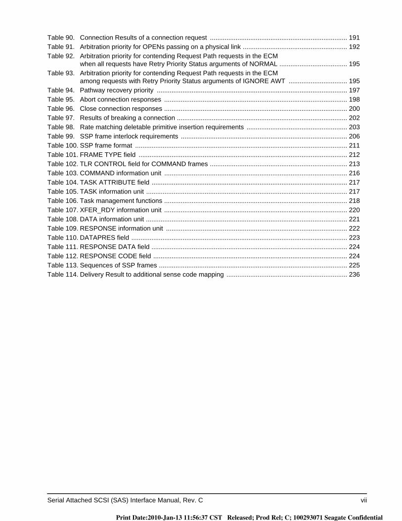
Table 90. Connection Results of a connection request ........................................................................... 191Table 91. Arbitration priority for OPENs passing on a physical link ......................................................... 192Table 92. Arbitration priority for contending Request Path requests in the ECM
when all requests have Retry Priority Status arguments of NORMAL ..................................... 195Table 93. Arbitration priority for contending Request Path requests in the ECM
among requests with Retry Priority Status arguments of IGNORE AWT ................................ 195Table 94. Pathway recovery priority ........................................................................................................ 197Table 95. Abort connection responses .................................................................................................... 198Table 96. Close connection responses .................................................................................................... 200Table 97. Results of breaking a connection ............................................................................................. 202Table 98. Rate matching deletable primitive insertion requirements ....................................................... 203Table 99. SSP frame interlock requirements ........................................................................................... 206Table 100. SSP frame format .................................................................................................................... 211Table 101. FRAME TYPE field .................................................................................................................. 212Table 102. TLR CONTROL field for COMMAND frames ........................................................................... 213Table 103. COMMAND information unit .................................................................................................... 216Table 104. TASK ATTRIBUTE field ........................................................................................................... 217Table 105. TASK information unit .............................................................................................................. 217Table 106. Task management functions .................................................................................................... 218Table 107. XFER_RDY information unit .................................................................................................... 220Table 108. DATA information unit .............................................................................................................. 221Table 109. RESPONSE information unit ................................................................................................... 222Table 110. DATAPRES field ...................................................................................................................... 223Table 111. RESPONSE DATA field ........................................................................................................... 224Table 112. RESPONSE CODE field .......................................................................................................... 224Table 113. Sequences of SSP frames ....................................................................................................... 225Table 114. Delivery Result to additional sense code mapping .................................................................. 236
Print Date:2010-Jan-13 11:56:37 CST Released; Prod Rel; C; 100293071 Seagate Confidential

viii Serial Attached SCSI (SAS) Interface Manual, Rev. C
List of Figures
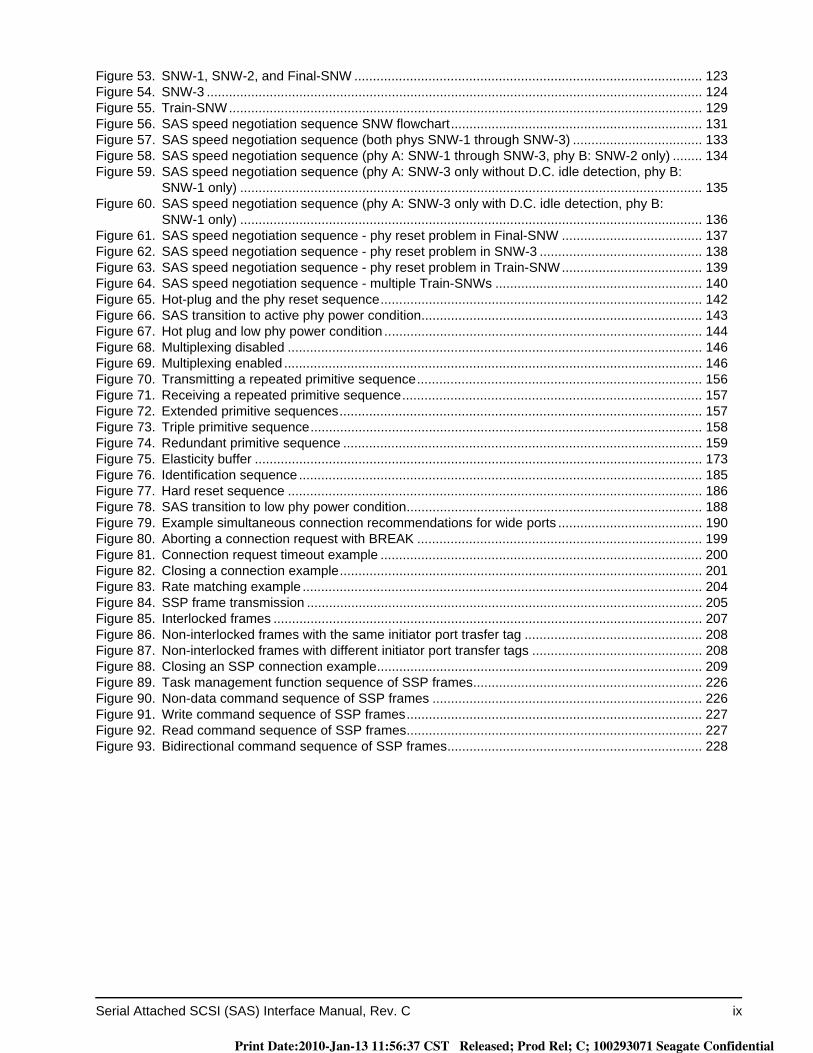
Figure 1. Functional scope ........................................................................................................................... 2Figure 2. SCSI client-server model .............................................................................................................. 5Figure 3. SCSI client-server model with service delivery subsystem ........................................................... 5Figure 4. Physical links and phys ............................................................................................................... 20Figure 5. Ports (narrow ports and wide ports) ............................................................................................ 22Figure 6. SAS devices................................................................................................................................ 23Figure 7. Expander device ......................................................................................................................... 24Figure 8. Domains ...................................................................................................................................... 25Figure 9. Devices spanning SAS domains ................................................................................................. 26Figure 10. Single expander device topology example.................................................................................. 26Figure 11. Multiple expander device topologies ........................................................................................... 27Figure 12. Potential pathways ...................................................................................................................... 28Figure 13. Multiple connections on wide ports ............................................................................................. 30Figure 14. Reset terminology ....................................................................................................................... 33Figure 15. Maximum limits for S-parameters definitions .............................................................................. 45Figure 16. TxRx connection |SDD22|, |SCD22|, |SCD21|, and NEXT limits...................................................... 51Figure 17. Zero-length test load for transmitter device compliance point..................................................... 52Figure 18. Zero-length test load for receiver device compliance point ......................................................... 53Figure 19. Zero-length test load |SDD21(f)| requirements ............................................................................. 54Figure 20. TCTF test load ............................................................................................................................ 54Figure 21. TCTF test load |SDD21(f)| and ISI loss requirements at IT for untrained 3 Gbps......................... 55Figure 22. TCTF test load |SDD21(f)| and ISI loss requirements at CT for untrained 3 Gbps ....................... 56Figure 23. TCTF test load |SDD21(f)| and ISI loss requirements at IT for untrained 1.5 Gbps...................... 57Figure 24. TCTF test load |SDD21(f)| and ISI loss requirements at CT for untrained 1.5 Gbps .................... 58Figure 25. Low-loss TCTF test load ............................................................................................................. 58Figure 26. Low-loss TCTF test load |SDD21(f)| and ISI loss requirements ................................................... 59Figure 27. Reference transmitter test load |SDD21(f)| up to 6 GHz............................................................... 60Figure 28. Reference transmitter test load impulse response...................................................................... 61Figure 29. Reference transmitter test load pulse response.......................................................................... 61Figure 30. Reference transmitter test load D24.3 response......................................................................... 62Figure 31. Transmitter device transient test circuit....................................................................................... 64Figure 32. Receiver device transient test circuit........................................................................................... 64Figure 33. Transmitter device eye mask ...................................................................................................... 65Figure 34. Receiver device eye mask .......................................................................................................... 66Figure 35. Deriving a receiver device jitter tolerance eye mask for untrained 1.5 Gbps and 3 Gbps .......... 67Figure 36. Transmitter device common mode voltage limit .......................................................................... 72Figure 37. Transmitter device |SCC22|, |SDD22|, and |SCD22| limits............................................................... 74Figure 38. Reference transmitter device ...................................................................................................... 75Figure 39. Reference transmitter device termination S-parameters............................................................. 76Figure 40. Transmitter equalization measurement....................................................................................... 77Figure 41. Applied SJ for untrained 1.5 Gbps and 3 Gbps........................................................................... 84Figure 42. Receiver device |SCC11|, |SDD11|, and |SCD11| limits................................................................... 86Figure 43. Reference receiver device .......................................................................................................... 87Figure 44. Reference receiver device termination S-parameters................................................................. 88Figure 45. Stressed receiver device jitter tolerance test block diagram ....................................................... 89Figure 46. Stressed receiver device jitter tolerance test D24.3 eye opening ............................................... 91Figure 47. Applied SJ for trained 1.5 Gbps, 3 Gbps, and 6 Gbps without SSC support .............................. 93Figure 48. Applied SJ for trained 1.5 Gbps, 3 Gbps, and 6 Gbps with SSC support ................................... 93Figure 49. Center-spreading tolerance buffer .............................................................................................. 98Figure 50. OOB signal transmission........................................................................................................... 114Figure 51. OOB signal detection ................................................................................................................ 117Figure 52. SAS to SAS OOB sequence ..................................................................................................... 120
Print Date:2010-Jan-13 11:56:37 CST Released; Prod Rel; C; 100293071 Seagate Confidential
Serial Attached SCSI (SAS) Interface Manual, Rev. C ix
Figure 53. SNW-1, SNW-2, and Final-SNW .............................................................................................. 123Figure 54. SNW-3 ...................................................................................................................................... 124Figure 55. Train-SNW................................................................................................................................ 129Figure 56. SAS speed negotiation sequence SNW flowchart.................................................................... 131Figure 57. SAS speed negotiation sequence (both phys SNW-1 through SNW-3) ................................... 133Figure 58. SAS speed negotiation sequence (phy A: SNW-1 through SNW-3, phy B: SNW-2 only) ........ 134Figure 59. SAS speed negotiation sequence (phy A: SNW-3 only without D.C. idle detection, phy B:
SNW-1 only) ............................................................................................................................. 135Figure 60. SAS speed negotiation sequence (phy A: SNW-3 only with D.C. idle detection, phy B:
SNW-1 only) ............................................................................................................................. 136Figure 61. SAS speed negotiation sequence - phy reset problem in Final-SNW ...................................... 137Figure 62. SAS speed negotiation sequence - phy reset problem in SNW-3 ............................................ 138Figure 63. SAS speed negotiation sequence - phy reset problem in Train-SNW...................................... 139Figure 64. SAS speed negotiation sequence - multiple Train-SNWs ........................................................ 140Figure 65. Hot-plug and the phy reset sequence....................................................................................... 142Figure 66. SAS transition to active phy power condition............................................................................ 143Figure 67. Hot plug and low phy power condition ...................................................................................... 144Figure 68. Multiplexing disabled ................................................................................................................ 146Figure 69. Multiplexing enabled ................................................................................................................. 146Figure 70. Transmitting a repeated primitive sequence............................................................................. 156Figure 71. Receiving a repeated primitive sequence................................................................................. 157Figure 72. Extended primitive sequences.................................................................................................. 157Figure 73. Triple primitive sequence.......................................................................................................... 158Figure 74. Redundant primitive sequence ................................................................................................. 159Figure 75. Elasticity buffer ......................................................................................................................... 173Figure 76. Identification sequence ............................................................................................................. 185Figure 77. Hard reset sequence ................................................................................................................ 186Figure 78. SAS transition to low phy power condition................................................................................ 188Figure 79. Example simultaneous connection recommendations for wide ports ....................................... 190Figure 80. Aborting a connection request with BREAK ............................................................................. 199Figure 81. Connection request timeout example ....................................................................................... 200Figure 82. Closing a connection example.................................................................................................. 201Figure 83. Rate matching example ............................................................................................................ 204Figure 84. SSP frame transmission ........................................................................................................... 205Figure 85. Interlocked frames .................................................................................................................... 207Figure 86. Non-interlocked frames with the same initiator port trasfer tag ................................................ 208Figure 87. Non-interlocked frames with different initiator port transfer tags .............................................. 208Figure 88. Closing an SSP connection example........................................................................................ 209Figure 89. Task management function sequence of SSP frames.............................................................. 226Figure 90. Non-data command sequence of SSP frames ......................................................................... 226Figure 91. Write command sequence of SSP frames................................................................................ 227Figure 92. Read command sequence of SSP frames................................................................................ 227Figure 93. Bidirectional command sequence of SSP frames..................................................................... 228
Print Date:2010-Jan-13 11:56:37 CST Released; Prod Rel; C; 100293071 Seagate Confidential

x Serial Attached SCSI (SAS) Interface Manual, Rev. C
Print Date:2010-Jan-13 11:56:37 CST Released; Prod Rel; C; 100293071 Seagate Confidential

Serial Attached SCSI (SAS) Interface Manual, Rev. C 1
1.0 Interface requirements
1.1 Acknowledgements
The information contained in this publication was gathered from many sources. Portions of the text used to explain general SAS concepts were adapted in various forms, with permission, from the SCSI Trade Associa-tion, and the T10/1760-D SAS-2 Interface Standard Revision 16.
1.2 How to use this interface manual
This manual provides a description of the Serial Attached SCSI (SAS) interface protocol and some general tim-ing information as implemented by Seagate products. Each individual drive’s Product Manual for the various SAS interface products contains additional and more detailed information on protocol, features supported and electrical/mechanical aspects of how the SAS interface is implemented by that product.
This manual provides a general, tutorial-type description of the ANSI SAS system. It is not intended to give all of the kinds of details needed to design/implement a SAS system or product.
For information about SAS interface details not included herein or in the individual drive product manuals, refer to the specifications listed in 1.2.2.
Note. The individual drive’s product manual has tables that specify which SCSI features the drive imple-ments, what the default parameters are for the various features they implement, which parameters are changeable, and which are not.
Note. SCSI commands are documented in the SCSI Commands Reference Manual, part number 100293068.
The combination of this specification together with the SCSI Commands Reference Manual and details in the individual drive’s product manual, provides a description of how a particular product implements the SAS I/O system. This interface manual is intended to be used in conjunction with the individual drive’s product manual and the SCSI Commands Reference Manual.
Print Date:2010-Jan-13 11:56:37 CST Released; Prod Rel; C; 100293071 Seagate Confidential
2 Serial Attached SCSI (SAS) Interface Manual, Rev. C
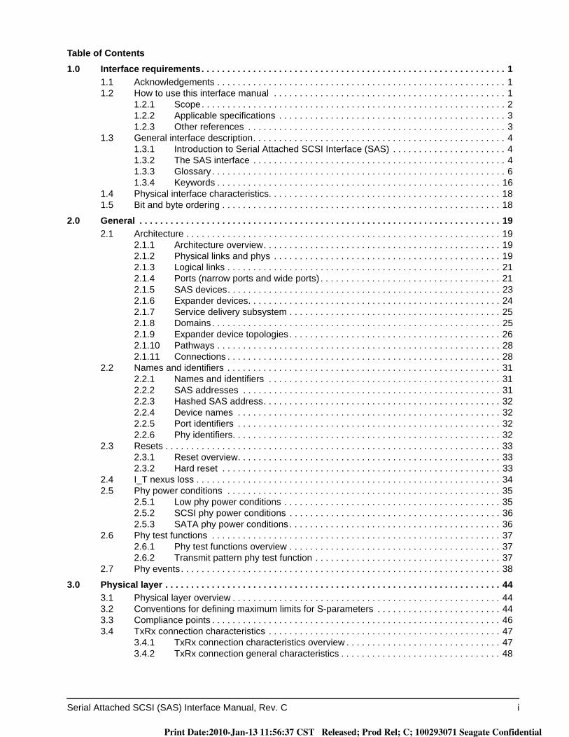
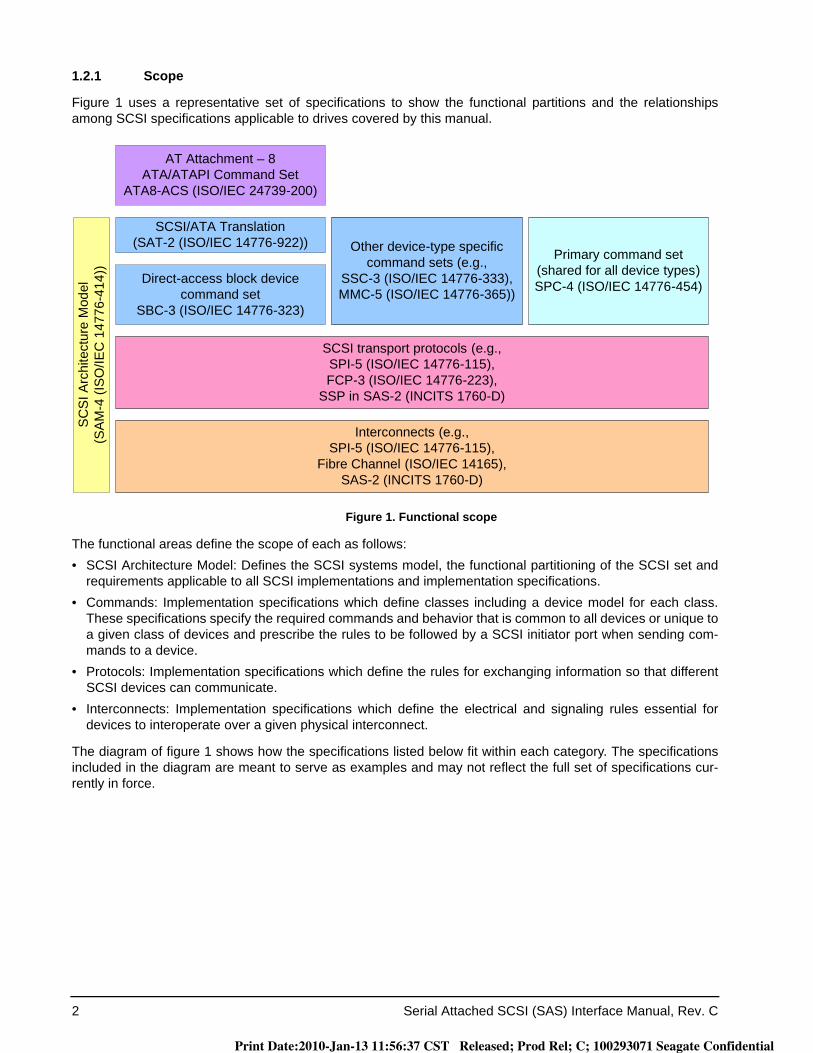
1.2.1 Scope
Figure 1 uses a representative set of specifications to show the functional partitions and the relationships among SCSI specifications applicable to drives covered by this manual.
Figure 1. Functional scope
The functional areas define the scope of each as follows:• SCSI Architecture Model: Defines the SCSI systems model, the functional partitioning of the SCSI set and
requirements applicable to all SCSI implementations and implementation specifications.• Commands: Implementation specifications which define classes including a device model for each class.
These specifications specify the required commands and behavior that is common to all devices or unique to a given class of devices and prescribe the rules to be followed by a SCSI initiator port when sending com-mands to a device.
• Protocols: Implementation specifications which define the rules for exchanging information so that different SCSI devices can communicate.
• Interconnects: Implementation specifications which define the electrical and signaling rules essential for devices to interoperate over a given physical interconnect.
The diagram of figure 1 shows how the specifications listed below fit within each category. The specifications included in the diagram are meant to serve as examples and may not reflect the full set of specifications cur-rently in force.
Direct-access block device command set
SBC-3 (ISO/IEC 14776-323)
SCSI transport protocols (e.g., SPI-5 (ISO/IEC 14776-115),FCP-3 (ISO/IEC 14776-223),
SSP in SAS-2 (INCITS 1760-D)
Interconnects (e.g.,SPI-5 (ISO/IEC 14776-115),
Fibre Channel (ISO/IEC 14165), SAS-2 (INCITS 1760-D)
SC
SI A
rchi
tect
ure
Mod
el(S
AM
-4 (I
SO
/IEC
147
76-4
14))
SCSI/ATA Translation(SAT-2 (ISO/IEC 14776-922))
Primary command set(shared for all device types)SPC-4 (ISO/IEC 14776-454)
Other device-type specific command sets (e.g.,
SSC-3 (ISO/IEC 14776-333),MMC-5 (ISO/IEC 14776-365))
AT Attachment – 8ATA/ATAPI Command Set
ATA8-ACS (ISO/IEC 24739-200)
Print Date:2010-Jan-13 11:56:37 CST Released; Prod Rel; C; 100293071 Seagate Confidential

Serial Attached SCSI (SAS) Interface Manual, Rev. C 3
1.2.2 Applicable specifications
The following ANSI specifications should be referenced for more details about SCSI system specifications of operation:• SCSI Architecture Model-4 (SAM-4), T10/1683-D• SCSI Enclosure Services - 2 (SES-2), T10/1559-D• SCSI Block Commands - 3 (SBC-3), T10/1799-D• SCSI Primary Commands-4 (SPC-4), T10/1731-D• SCSI Serial Attached SCSI - 2 (SAS-2) T10/1760-D• SAS Protocol Layer (SPL) T10/1562-D• Fibre Channel Protocol for SCSI, Third Version (FCP-3) T10/1560-D
1.2.3 Other references
For information on the current status of the listed documents, or regarding availability, contact the indicated organization.• SFF-8223, 2.5" Drive Form Factor with Serial Connector• SFF-8323, 3.5" Drive Form Factor with Serial Connector• SFF-8523, 5.25" Drive Form Factor with Serial Connector• SFF-8410, HSS Copper Testing and Performance Requirements• SFF-8460, HSS Backplane Design Guidelines• SFF-8470, Multi Lane Copper Connector• SFF-8482, SAS Plug Connector
Print Date:2010-Jan-13 11:56:37 CST Released; Prod Rel; C; 100293071 Seagate Confidential

4 Serial Attached SCSI (SAS) Interface Manual, Rev. C
1.3 General interface description
This SAS Interface Manual describes the Seagate Technology, Inc. subset of the Serial Attached SCSI (Small Computer Systems Interface) as implemented on the Seagate-built drives. The interface is compatible with the SCSI Interface Specifications listed in 1.2.2. The drives covered by this product manual are classified as “Intel-ligent” peripherals.
1.3.1 Introduction to Serial Attached SCSI Interface (SAS)
The SAS interface provides several advantages over Parallel SCSI. Parallel SCSI has reached a practical maximum transfer rate of 320 MB/sec. Parallel SCSI is limited to a maximum of 16 devices connected to the bus, one of which must be a host bus adapter. Fibre Channel (FC) allows SCSI to be transmitted in a serial manner using frames, rather than on a parallel bus. It allows up to 127 devices to be addressed on fibre optic cable, or copper conductors. FC devices are connected in a loop and arbitrate for control of the loop, using fibre optic cable devices may be physically separated by 10km of cable. Parallel ATA (PATA) is limited to a maximum of two devices per host adapter, lower data transfer rates, and is not considered intelligent, there-fore, not well suited for enterprise environments. Serial ATA (SATA) increases the data transfer rate but is lim-ited in addressing, and cable length, and intelligence. SATA uses small form cables and connectors to transfer data at up 300 MB/sec, with the standard allowing transmission of up to 600 MB/sec. Currently SATA is a point-to-point connection inside the computer’s system unit, with a maximum length of 18 inches. External SATA is in the development stage.
SAS combines the intelligence of SCSI with the physical transport layer. This scheme allows the intelligence of SCSI to be transferred on a serial cable similar to SATA. Data is transfer in frames, like Fibre Channel. The ini-tial data transfer rate for SAS was 300 MB/sec. with the SAS-2 standard allowing up to 600 MB/sec. SAS pro-vides for full duplex operation, at 300 MB/sec. it is possible to attain 600 MB/sec. per pathway. SAS is a point to point connection as is SATA, Expanders are used to increase the number of devices that may be connected. Unlike Parallel SCSI and Fibre Channel SAS drives and Serial ATA drives may be attached to the same expander.
1.3.2 The SAS interface
The Seagate SAS interface described herein consists of a dual ported SAS bidirectional links. The SCSI inter-face supports multiple initiators, disconnect/reconnect, self-configuring host software, automatic features that relieve the host from the necessity of knowing the physical architecture of the target (logical block addressing is used), and some other miscellaneous features.
Unless specified otherwise in the individual drive’s product manual, the drive is always a SAS target port, and never a SAS initiator port. For certain commands, which may or may not be supported by a particular drive model, the drive must act as a SAS initiator port, but does not otherwise do so. For purposes of this specifica-tion, “drive” may be substituted for the word “target” wherever “target” appears.
In the event of a conflict between this document and ANSI SCSI documents, the requirements of the ANSI doc-uments shall apply.
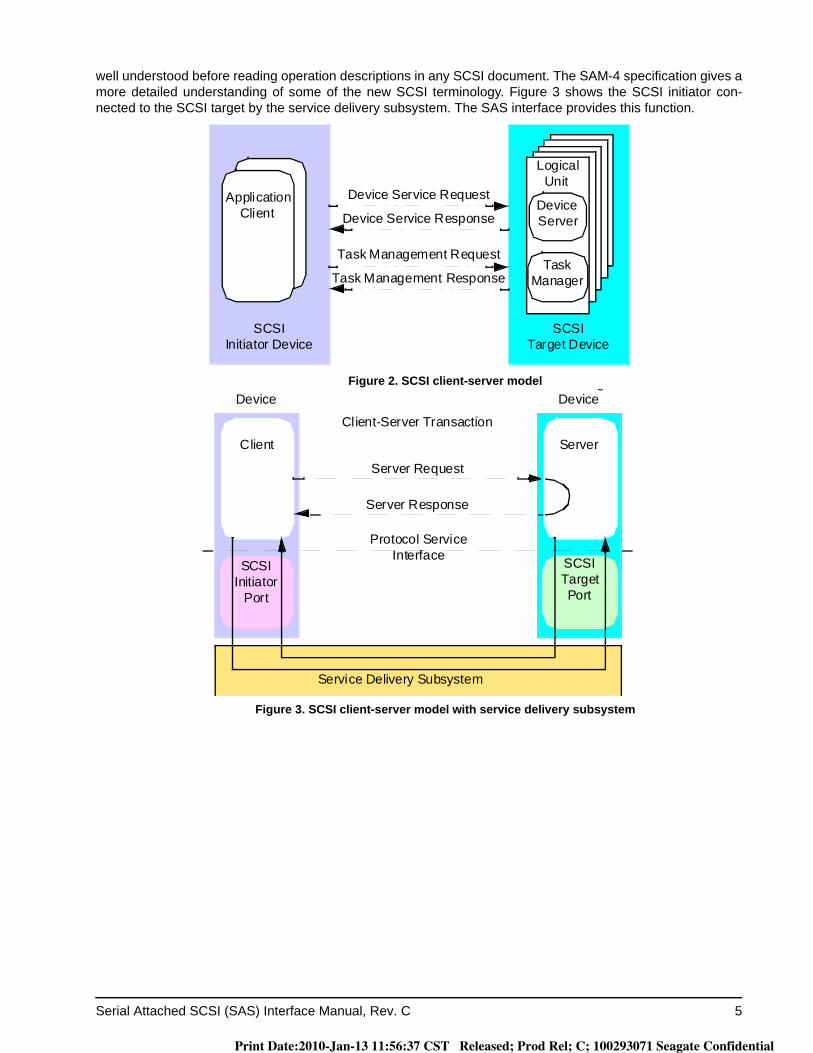
In figure 2, it can be seen that several “application clients” from a single initiator may have one or more tasks in queue with several “device servers” in a single target. A drive could be a SCSI target port or it could be one of the device servers as part of some larger entity. When reading the description, one needs to be able to put the drive of interest in the proper context in terms of what is shown in figure 2. For a proper understanding of the operation of the SCSI protocol, the terms in the SCSI architectural model as described in SAM-4 should be
Print Date:2010-Jan-13 11:56:37 CST Released; Prod Rel; C; 100293071 Seagate Confidential
Serial Attached SCSI (SAS) Interface Manual, Rev. C 5
well understood before reading operation descriptions in any SCSI document. The SAM-4 specification gives a more detailed understanding of some of the new SCSI terminology. Figure 3 shows the SCSI initiator con-nected to the SCSI target by the service delivery subsystem. The SAS interface provides this function.
Figure 2. SCSI client-server model
Figure 3. SCSI client-server model with service delivery subsystem
Logical Unit
Device Server
Task Management Response
SCSITarget Device
SCSIInitiator Device
Application Client
Device Service Request
Device Service Response
Task Management RequestTask
Manager
Client
Client-Server Transaction
Server Response
Server Request
Protocol ServiceInterface
Deviceg
Device
Service Delivery Subsystem
SCSI Target Port
SCSI Initiator
Port
Server
Print Date:2010-Jan-13 11:56:37 CST Released; Prod Rel; C; 100293071 Seagate Confidential

6 Serial Attached SCSI (SAS) Interface Manual, Rev. C
1.3.3 Glossary
8b 10b coding—A coding scheme that represents an 8-bit data byte as a 10-bit character.
aborted command—A SCSI command that has been ended by aborting the task created to execute it.
ACA—Auto Contingent Allegiance (see below).
ACA command—A command performed by a task with the ACA attribute. For additional information about the ACA command, refer to the Seagate SCSI Commands Reference Manual.
ACK—Acknowledge primitive that specifies the positive acknowledgement of an SSP frame.
application client—An object that is the source of SCSI commands. An object in this sense is not a tangible piece of hardware, but may be a single numeric parameter, such as a logical unit number, or a complex entity that performs a set of operations or services on behalf of another object (see SAM-4).
auto contingent allegiance—One of the conditions of a task set following the return of a CHECK CONDITION status.
big-endian: A format for storage or transmission of binary data in which the most significant byte appears first. In a multi-byte value, the byte containing the most significant bit is stored in the lowest memory address and transmitted first and the byte containing the least significant bit is stored in the highest memory address and transmitted last (e.g., for the value 0080h, the byte containing 00h is stored in the lowest memory address and the byte containing 80h is stored in the highest memory address).
blocked (task state)—The state of a task that is prevented from completing due to an ACA condition.
broadcast primitive processor (BPP)—An object within an expander function that manages broadcast primi-tives.
burst time—The part of an OOB signal (see 4.5) where ALIGN primitives (see 5.2.5.1) are being transmitted.
byte—A sequence of eight contiguous bits considered as a unit.
call—The act of invoking a procedure.
character—A sequence of ten contiguous bits considered as a unit. A byte is encoded as a character using 8b10b coding.
client-server—A relationship established between a pair of distributed objects where one (the client) requests the other (the server) to perform some operation or unit of work on the client’s behalf (see SAM-4).
Client—An object that requests a service from a server.
command—A request describing a unit of work to be performed by a device server.
command descriptor block (CDB)—A structure used to communicate a command from a SCSI application client to a SCSI device server. See SAM-4.
common SSC transmit clock: An implementation that employs a single transmit clock for multiple transmitter devices and enables or disables SSC(see 3.6.6) on the transmit clock signal to all transmitter devices in com-mon rather than allowing each transmitter device to independently control SSC.
compliance point: An interoperability point where interoperability specifications are met. See .
compliant jitter tolerance pattern (CJTPAT): A test pattern for jitter testing. See 3.6.5.6.
completed command—A command that has ended by returning a status and service response of Task Com-plete or Linked Command Complete.
completed task—A task that has ended by returning a status and service response of Task Complete. The actual events comprising the Task Complete response are protocol specific.
Print Date:2010-Jan-13 11:56:37 CST Released; Prod Rel; C; 100293071 Seagate Confidential
Serial Attached SCSI (SAS) Interface Manual, Rev. C 7
configurable expander device—An expander device that contains an expander route table that is configured with expander route entries.
confirmation—A response returned to an object, which signals the completion of a service request.
confirmed service—A service available at the protocol service interface, which requires confirmation of com-pletion. The confirmed service consists of the request and confirmation steps and optionally the indication and response steps.
connection—A temporary association between a SAS initiator port and a SAS target port.
connection rate—The effective rate of dwords through the pathway between a SAS initiator phy and a SAS target phy, established through the connection request.
control character (Kxx.y)—A character that does not represent a byte of data.
control mode page—The mode page that identifies the settings of several device server behaviors that may be of interest to an application client or may be changed by an application client. The complete definition of the Control mode page is found in the Seagate SCSI Commands Reference Manual.
current task—A task that is in the process of sending messages, sending status, transferring data, or transfer-ring command data to or from the initiator.cyclic redundancy check (CRC)—An error checking mechanism that checks data integrity by computing a polynomial algorithm based checksum (see 5.5).
data character (Dxx.y)—A character representing a byte of data.
data dword—A dword that starts with a Dxx.y (data character).
D.C. idle—A differential signal level that is nominally 0 V(P-P).
deadlock—A condition in which two or more processes (e.g., connection requests) are waiting on each other to complete, resulting in none of the processes completing.
destination device—The SCSI device to which a service delivery transaction is addressed. See source device.
deterministic jitter—Jitter with a non-Gaussian probability density function. Deterministic jitter is always bounded in amplitude and has specific causes. Four kinds of deterministic jitter are identified: duty cycle distor-tion, data dependent, sinusoidal, and uncorrelated (to the data) bounded. Deterministic jitter is characterized by its bounded, peak-to-peak value.
device name— A worldwide unique name for a device within a transport protocol.
device server—An object within a SAS target device that processes SCSI tasks (see SAM-4).
device service request—A request, submitted by an application client, conveying a SCSI command to a device server.
device service response—The response returned to an application client by a device server on completion of a SCSI command.
differential—A signalling alternative that employs differential (two complementary signals) drivers and receiv-ers to improve signal-to-noise ratios and increase maximum cable lengths.
direct current (D.C.)—The non-A.C. component of a signal. In this, all frequency components below 100 kHz.
discover process—The algorithm used by a management application client to configure the SAS domain. See SAS-2.
disparity—The difference between the number of ones and zeros in a character.
Print Date:2010-Jan-13 11:56:37 CST Released; Prod Rel; C; 100293071 Seagate Confidential
8 Serial Attached SCSI (SAS) Interface Manual, Rev. C
domain—A SAS domain, a SCSI domain, or an ATA domain.
dword—A sequence of four contiguous bytes or four contiguous characters considered as a unit. The meaning depends on the context (e.g., when discussing the bits being transmitted over a physical link, dword represents four characters (i.e., 40 bits). When discussing the contents of a frame after 10b8b decoding (see 4.2), dword represents four bytes (i.e., 32 bits)).
dword synchronization—Detection of an incoming stream of dwords from a physical link by a phy.
expander connection manager (ECM)—An object within an expander function that manages routing.
expander connection router (ECR)—The portion of an expander function that routes messages between expander phys.
enabled (task state)—The state of a task that may complete at any time. Alternatively, the state of a task that is waiting to receive the next command in a series of linked commands.
end device—A SAS device that is not contained within an expander device.
ended command—A command that has completed or aborted.
event notification—A message passed from the transport layer to the application layer notifying the applica-tion layer that a SCSI event has occurred. See SAM-4.
exception condition—Any event that causes a SCSI device to enter an auto contingent allegiance or contin-gent allegiance condition.
expander device—A device that is part of the service delivery subsystem and facilitates communication between SAS devices.
expander function—An object within an expander device that contains an expander connection manager, expander connection router, and broadcast primitive processor.
expander phy—A phy in an expander device that interfaces to a service delivery subsystem.
expander port—An expander device object that interfaces to the service delivery subsystem and to SAS ports in other devices.
expander route entry—A routed SAS address and an enable/disable bit in an expander route table.
expander route index—A value used in combination with a phy identifier to select an expander route entry in an expander route table.
faulted initiator—The initiator to which a Command Terminated or CHECK CONDITION status was returned.
faulted task set—A task set that contained a faulting task.
faulting command—A command that completed with a status of Check Condition or Command Terminated.
faulting task—A task that has completed with a status of Check Condition or Command Terminated.
field—A group of one or more contiguous bits.
frame—A sequence of data dwords between a start of frame primitive (e.g., SOF, SOAF, or SATA_SOF) and an end of frame primitive (e.g., EOF, EOAF, or SATA_EOF).
hard reset—A SAS device or expander device action in response to a reset event.
Hard reset sequence—A sequence that causes a hard reset.
hardware maximum physical link rate—The maximum physical link rate capability of a phy.
hardware minimum physical link rate—The minimum physical link rate capability of a phy.
Print Date:2010-Jan-13 11:56:37 CST Released; Prod Rel; C; 100293071 Seagate Confidential

Serial Attached SCSI (SAS) Interface Manual, Rev. C 9
hash function—A mathematical function that maps values from a larger set of values into a smaller set of val-ues, reducing a long value into a shorter hashed value.
identification sequence—A sequence where phys exchange IDENTIFY address frames.
idle dword—A vendor-specific data dword that is scrambled and is transmitted outside a frame.
idle time—The part of an OOB signal where D.C. idle is being transmitted.
implementation-specific—A requirement or feature that is defined in a SCSI but whose implementation may be specified by the system integrator or vendor.
implementation option—An option whose actualization within an implementation is at the discretion of the implementor.
information unit (IU)—The portion of an SSP frame that carries command, task management function, data, response, or transfer ready information.
initiator—A SCSI device containing application clients which originate device service and task management requests to be processed by a SCSI target port SCSI device.
invalid dword—A dword with an illegal character, with a control character in other than the first character posi-tion, with a control character other than K28.5 or K28.3 in the first character position, or with a running disparity error.
I/O operation—An operation defined by an unlinked SCSI command, a series of linked SCSI commands or a task management function.
I_T nexus—A nexus that exists between a SCSI initiator port and a SCSI target port.
I_T nexus loss—A condition where a SAS port determines that another SAS port is no longer available.
I_T_L nexus—A nexus that exists between a SCSI initiator port, a SCSI target port, and a logical unit. This relationship extends the prior I_T nexus.
I_T_L_Q nexus—A nexus between a SCSI initiator port, a SCSI target port, a logical unit, and a tagged task. This relationship extends the prior I_T nexus or I_T_L nexus.
jitter—Abrupt and unwanted variations in the interval between successive pulses.
layer—A subdivision of the architecture constituted by subsystems of the same rank.
least significant bit (LSB)—In a binary code, the bit or bit position with the smallest numerical weighting in a group of bits that, when taken as a whole, represent a numerical value (e.g., in the number 0001b, the bit that is set to one).
linked CDB—A CDB with the link bit in the control byte set to one.
linked command—One in a series of SCSI commands executed by a single task, which collectively make up a discrete I/O operation. In such a series, each command has the same task identifier, and all except the last have the link bit in the CDB control byte set to one.
link reset—Performing the link reset sequence
link reset sequence—For SATA, a phy reset sequence. For SAS, a phy reset sequence followed by an identi-fication sequence, or a phy reset sequence followed by a hard reset sequence, another phy reset sequence, and an identification sequence.
Print Date:2010-Jan-13 11:56:37 CST Released; Prod Rel; C; 100293071 Seagate Confidential
10 Serial Attached SCSI (SAS) Interface Manual, Rev. C
little-endian—A format for storage or transmission of binary data in which the least significant byte appears first. In a multi-byte value, the byte containing the least significant bit is stored in the lowest memory address and transmitted first and the byte containing the most significant bit is stored in the highest memory address and transmitted last (e.g., for the value 0080h, the byte containing 80h is stored in the lowest memory address and the byte containing 00h is stored in the highest memory address).
livelock—A condition where two or more processes (e.g., connection requests) continually change their state in response to changes in other processes, resulting in none of the processes completing.
logical unit—a SCSI target port-resident entity which implements a device model and executes SCSI com-mands sent by an application client.
logical unit number—A 64-bit identifier for a logical unit.
logical unit option—An option pertaining to a logical unit, whose actualization is at the discretion of the logical unit implementor.
lower level protocol—A protocol used to carry the information representing upper level protocol transactions.
media—Particular elements comprising the interconnect including copper cables, printed circuit boards, and other transmission line materials.
media information—Information stored within a SCSI device which is non-volatile (retained through a power cycle) and accessible to a SCSI initiator port through the execution of SCSI commands.
most significant bit (MSB)—In a binary code, the bit or bit position with the largest numerical weighting in a group of bits that, when taken as a whole, represent a numerical value (e.g., in the number 1000b, the bit that is set to one).
multidrop—A characteristic of the SCSI bus that allows SCSI devices to be connected to the SCSI bus with-out disrupting the electrical path between the terminators.
multimode single-ended (MSE)—A signalling alternative for multimode SCSI devices that employs MSE driv-ers and receivers to allow multimode SCSI devices to operate when SE SCSI devices are present on the bus.
NAK—Specifies the negative acknowledgement of an SSP frame and the reason for doing so.
narrow link—A physical link that attaches a narrow port to another narrow port.
narrow port—A port that contains exactly one phy.
negotiated physical link rate—The current operational physical link rate established after speed negotiation between two phys.
nexus—When referring to SAS devices, a relationship between two SAS devices, and the SAS initiator port and the SAS target port objects within those SAS devices. When referring to SCSI devices, a relationship between two SCSI devices, and the SCSI initiator port and the SCSI target port objects within those SCSI devices. See SAM-4.
object—An architectural abstraction or “container” that encapsulates data types, services, or other objects that are related in some way.
OOB sequence—A sequence where two phys exchange OOB signals.
OOB signal—Pattern of ALIGNs and idle time used during the link reset sequence.
partial pathway—The set of physical links participating in a connection request which has not reached a SAS endpoint (i.e., the connection request has been transmitted by the source device and confirmed as received by at least one expander device with AIP).
pathway—A set of physical links between a SAS initiator phy and a SAS target phy being used by a connec-tion.
Print Date:2010-Jan-13 11:56:37 CST Released; Prod Rel; C; 100293071 Seagate Confidential
Serial Attached SCSI (SAS) Interface Manual, Rev. C 11
pathway blocked count—The number of times the port has retried this connection request due to receiving OPEN_REJECT (PATHWAY BLOCKED).
pending task—A task that is not a current task.
phy—A device object that is used to interface to other devices.
phy reset sequence—An OOB sequence (see ) followed by a speed negotiation sequence (see ).
physical link—Two differential signal pairs, one pair in each direction, that connect two physical phys.
physical phy—A phy (see ) that contains a transceiver and electrically interfaces to a physical link to commu-nicate with another physical phy.
port—A SAS port or an expander port. Each port contains one or more phys.
potential pathway—A set of physical links between a SAS initiator phy and a SAS target phy.
power on—Power being applied.
primitive—A dword starting with K28.5 or K28.3 followed by three data characters.
primitive sequence—A set of primitives treated as a single entity.
procedure—An operation that can be invoked through an external calling interface.
programmed maximum physical link rate—The maximum operational physical link rate of a phy (e.g., as programmed via the SMP PHY CONTROL function or the Phy Control and Discover subpage (see SAS-2).
programmed minimum physical link rate—The minimum operational physical link rate of a phy (e.g., as pro-grammed via the SMP PHY CONTROL function, the Phy Control and Discover subpage (see SAS-2).
protocol—The rules governing the content and exchange of information passed between distributed objects through the service delivery subsystem.
protocol option—An option whose definition within a SCSI protocol is discretionary.
protocol service confirmation—A signal from the lower level protocol service layer notifying the upper layer that a protocol service request has completed.
protocol service indication—A signal from the lower level protocol service layer notifying the upper level that a protocol transaction has occurred.
protocol service request—A call to the lower level protocol service layer to begin a protocol service transac-tion.
protocol service response—A reply from the upper level protocol layer in response to a protocol service indi-cation.
queue—The arrangement of tasks within a task set, usually according to the temporal order in which they were created. See task set.
queue tag—The parameter associated with a task that uniquely identifies it from other tagged tasks for a logi-cal unit from the same initiator.
random jitter—Jitter that is assumed to have a Gaussian distribution.
rate—Data transfer rate of a physical link (e.g., 1.5 Gbps or 3.0 Gbps).
rate change delay time (RCDT)—The time between rates during the speed negotiation sequence.
receiver circuit—An electronic circuit that converts an analog serial input signal to a logic signal.
Print Date:2010-Jan-13 11:56:37 CST Released; Prod Rel; C; 100293071 Seagate Confidential
12 Serial Attached SCSI (SAS) Interface Manual, Rev. C
receiver device (Rx): The device downstream from a receiver device compliance point containing a portion of the physical link and a receiver circuit.
reference receiver device: A set of parameters defining electrical performance characteristics that provide a set of minimum electrical performance requirements for a receiver device and that are also used in mathemat-ical modeling to determine compliance of a TxRx connection or transmitter device. See 3.6.5.7.3.
reference transmitter device: A set of parameters defining electrical performance characteristics of a trans-mitter device that are used in mathematical modeling to determine compliance of a TxRx connection. See 3.6.4.6.5.
reference transmitter test load: A set of S-parameters defining the electrical characteristics of a TxRx con-nection used as the basis for transmitter device and receiver device performance evaluation through mathe-matical modeling. See 3.5.5.
reflection coefficient —The ratio of reflected voltage to incident voltage.
reflection coefficient —The reflection coefficient of the transmission media (i.e., the ratio of the reflected volt-age divided by the voltage applied to the transmission media).
request-response transaction—An interaction between a pair of distributed, cooperating objects, consisting of a request for service submitted to an object followed by a response conveying the result.
request-confirmation transaction—An interaction between a pair of cooperating objects, consisting of a request for service submitted to an object followed by a response for the object confirming request completion.
reset event—An event that triggers a hard reset from a SAS device.
running disparity—A binary value indicating the cumulative encoded signal imbalance between the one and zero signal state of all characters since dword synchronization has been achieved.
SAS address— worldwide unique name assigned to a SAS initiator port, SAS target port, expander device, SAS initiator device, or SAS target device (see 2.2.2).
SAS device—A SAS initiator device, SAS target device, or SAS target/initiator device.
SAS domain—The I/O system defined by this that may serve as an ATA domain and/or a SCSI domain.
SAS initiator device—A device containing SSP, STP, and/or SMP initiator ports in a SAS domain.
SAS initiator phy—A phy in a SAS initiator device.
SAS initiator port—An SSP initiator port, STP initiator port, and/or SMP initiator port in a SAS domain.
SAS phy—A phy in a SAS device that interfaces to a service delivery subsystem.
SAS port—A SAS initiator port, SAS target port, or SAS target/initiator port.
SAS target device—A device containing SSP, STP, and/or SMP target ports in a SAS domain.
SAS target phy—A phy in a SAS target device.
SAS target port—An SSP target port, STP target port, and/or SMP target port in a SAS domain.
SAS target/initiator device—A device that has all the characteristics of a SAS target device and a SAS initia-tor device.
SAS target/initiator port—A port that has all the characteristics of a SAS target port and a SAS initiator port in a SAS domain.
scrambling—Modifying data by XORing each bit with a pattern generated by a linear feedback shift register to minimize repetitive character patterns.
Print Date:2010-Jan-13 11:56:37 CST Released; Prod Rel; C; 100293071 Seagate Confidential

Serial Attached SCSI (SAS) Interface Manual, Rev. C 13
SCSI application layer—The protocols and procedures that implement or invoke SCSI commands and task management functions by using services provided by a SCSI protocol layer.
SCSI device—A device that contains one or more SCSI ports that are connected to a service delivery subsys-tem and supports a SCSI application protocol. See SAM-4.
SCSI domain—An I/O system consisting of a set of SCSI devices that communicate with one another by means of a service delivery subsystem. See SAM-4.
SCSI initiator device—A SCSI device containing application clients and SCSI initiator ports that originates device service and task management requests to be processed by a SCSI target device and receives device service and task management responses from SCSI target devices. See SAM-4.
SCSI initiator port—A SCSI initiator device object that acts as the connection between application clients and the service delivery subsystem through which indications and responses are routed. See SAM-4.
SCSI port—A SCSI initiator port or a SCSI target port. See SAM-4.
SCSI target device—A SCSI device containing logical units and SCSI target ports that receives device service and task management requests for processing and sends device service and task management responses to SCSI initiator devices. See SAM-4.
SCSI target port—A SCSI target device object that contains a task router and acts as the connection between device servers and task managers and the service delivery subsystem through which requests and confirma-tions are routed. See SAM-4.
SCSI target/initiator device—A device that has all the characteristics of a SCSI target device and a SCSI ini-tiator device. See SAM-4.
SCSI target/initiator port—A SCSI target/initiator device object that has all the characteristics of a SCSI tar-get port and a SCSI initiator port. See SAM-4.
sender—A client or server that originates a service delivery transaction.
Serial ATA Tunneled Protocol (STP)—The protocol defined in this used by STP initiator ports to communi-cate with STP target ports in a SAS domain.
Serial Attached SCSI (SAS)—The set of protocols and the interconnect defined by this manual.
Serial Management Protocol (SMP)—The protocol defined in this used by SAS devices to communicate management information with other SAS devices in a SAS domain.
Serial SCSI Protocol (SSP)—The protocol defined in this used by SCSI initiator ports to communicate with SCSI target ports in a SAS domain.
server—A SCSI object that performs a service on behalf of a client.
service—Any operation or function performed by a SCSI object, which can be invoked by other SCSI objects.
service delivery failure—Any non-recoverable error causing the corruption or loss of one or more service delivery transactions while in transit.
service delivery port—A device-resident interface used by the application client, device server or task man-ager to enter and retrieve requests and responses from the service delivery subsystem. Synonymous with “port.”
service delivery subsystem—The part of a SCSI I/O system that transmits information between a SCSI initi-ator port and a SCSI target port, or the part of an ATA I/O system that transmits information between an ATA host and an ATA device, or the part of a SAS I/O system that transmits information between a SAS initiator port and a SAS target port.
service delivery transaction—A request or response sent through the service delivery subsystem.
Print Date:2010-Jan-13 11:56:37 CST Released; Prod Rel; C; 100293071 Seagate Confidential
14 Serial Attached SCSI (SAS) Interface Manual, Rev. C
signal—(n) A detectable asynchronous event possibly accompanied by descriptive data and parameters. (v) The act of generating such an event.
single transition (ST)—The latching of data only on the assertion edge of the REQ or ACK signals.
SMP initiator phy—A SAS initiator phy in an SMP initiator port.
SMP initiator port—A SAS initiator device object in a SAS domain that interfaces to the service delivery sub-system with SMP.
SMP phy—A SAS phy in an SMP port.
SMP port—An SMP initiator port, SMP target port, or SMP target/initiator port.
SMP target phy—A SAS target phy in an SMP target port.
SMP target port—A SAS target device object in a SAS domain that interfaces to the service delivery subsys-tem with SMP.
SMP target/initiator port—A port that has all the characteristics of an SMP initiator port and an SMP target port.
source device—The SCSI device from which a service delivery transaction originates. See destination device.
speed negotiation lock time (SNLT)—The maximum time during a speed negotiation window for a transmit-ter to reply with ALIGN (1).
speed negotiation sequence—A sequence in which two phys negotiate the operational physical link rate.
speed negotiation transmit time (SNTT)—The time during which ALIGN (0) or ALIGN (1) is transmitted dur-ing the speed negotiation sequence.
spread spectrum clocking—The technique of modulating the operating frequency of a transmitted signal to reduce the measured peak amplitude of radiated emissions.
SSP initiator phy—A SAS initiator phy in an SSP initiator port.
SSP initiator port—A SCSI initiator port in a SAS domain that implements SSP.
SSP phy—A SAS phy in an SSP port.
SSP port—An SSP initiator port, SSP target port, or SSP target/initiator port.
SSP target phy—A SAS target phy in an SSP target port.
SSP target port—A SCSI target port in a SAS domain that implements SSP.
SSP target/initiator port—A port that has all the characteristics of an SSP initiator port and an SSP target port.
STP initiator phy—A SAS initiator phy in an STP initiator port.
STP initiator port—A SAS initiator device object in a SAS domain that interfaces to the service delivery sub-system with STP.
STP phy—A SAS phy in an STP port.
STP port—An STP initiator port, STP target port, or STP target/initiator port.
STP target phy—A SAS target phy in an STP target port.
STP target port—A SAS target device object in a SAS domain that interfaces to the service delivery subsys-tem with STP.
Print Date:2010-Jan-13 11:56:37 CST Released; Prod Rel; C; 100293071 Seagate Confidential

Serial Attached SCSI (SAS) Interface Manual, Rev. C 15
STP target/initiator port—A port that has all the characteristics of an STP initiator port and an STP target port.
STP/SATA bridge—An expander device object containing an STP target port, a SATA host port, and the func-tions required to forward information between the STP target port and SATA host port to enable STP initiator ports in a SAS domain to communicate with SATA devices in an ATA domain.
subsystem—An element in a hierarchically partitioned system which interacts directly only with elements in the next higher division or the next lower division of that system.
subtractive routing attribute—The attribute of an expander phy that indicates it may be used by the expander connection manager to route connection requests not resolved using the direct routing method or table routing method.
subtractive routing method—The method the expander connection manager uses to route connection requests not resolved using the direct routing method or table routing method to an expander device.
suspended information—Information stored within a logical unit that is not available to any pending tasks.
table routing attribute—The attribute of an expander phy that indicates it may be used by the expander con-nection manager to route connection requests using an expander route table.
table routing method—The method the expander connection manager uses to route connection requests to an expander device using an expander route table.
target—A SCSI device which receives SCSI commands and directs such commands to one or more logical units for execution.
task—An object within the logical unit representing the work associated with a command or group of linked commands. A task consists of one initial connection and zero or more physical or logical reconnections, all per-taining to the task.
task abort event—An event or condition indicating that the task has been aborted by means of a task man-agement function.
task address—a SCSI initiator port identifies a task to a SCSI target port using a Task Address. The Task Address object represents either a Tagged Task Address or an Untagged Task Address without regard for the tagged or untagged nature of the Task. A Tagged Task Address is composed of a Logical Unit Identifier and a Tag. An Untagged Task Address is composed of a Logical Unit Identifier.
task completion event—An event or condition indicating that the task has ended with a service response of Task Complete.
task ended event—An event or condition indicating that the task has completed or aborted.
task management function—A task manager service which can be invoked by an application client to affect the execution of one or more tasks.
task management request—A request submitted by an application client, invoking a task management func-tion to be executed by a task manager.
task management response—The response returned to an application client by a task manager on comple-tion of a task management request.
task manager—A server within the target which executes task management functions.
task set—A group of tasks within a SCSI target port device, whose interaction is dependent on the queuing and auto contingent allegiance rules
task slot—Resources within the logical unit that may be used to contain a task.
Print Date:2010-Jan-13 11:56:37 CST Released; Prod Rel; C; 100293071 Seagate Confidential
16 Serial Attached SCSI (SAS) Interface Manual, Rev. C
task tags—A Tag is a field containing up to 64 bits that is a component of a Tagged Task Identifier. A SCSI ini-tiator port assigns tag values in each Tagged Task Identifier in a way that ensures that the identifier uniqueness requirements stated in SAM-4 are met.
third-party command—A SCSI command which requires a logical unit within the target device to assume the initiator role and send a SCSI command to a SCSI target port device.
total jitter—Measured jitter including deterministic jitter and random jitter.
transaction—A cooperative interaction between two objects, involving the exchange of information or the exe-cution of some service by one object on behalf of the other.
transceiver—An object that contains both transmitter and receiver objects.
transmitter circuit—An electronic circuit that converts a logic signal to an analog serial output signal.
transmitter compliance transfer function (TCTF)—The mathematical statement of the transfer function through which the transmitter shall be capable of producing acceptable signals as defined by a receive mask.
transmitter device (Tx): The device upstream from a transmitter device compliance point (see 3.1.34) con-taining a portion of the physical link and a transmitter circuit (see 3.1.283).
transport protocol service confirmation—A message passed from the transport layer to the application layer (i.e., from the SSP initiator port to the SCSI application client) that notifies the application layer that a SCSI transport protocol service has completed.
transport protocol service indication—A message passed from the transport layer to the application layer notifying the application layer (i.e., from the SSP target port to the SCSI device server) to begin a SCSI trans-port protocol service.
transport protocol service request—A message passed from the SCSI application layer to the SSP trans-port layer (i.e., from the SCSI application client to the SCSI initiator port) to begin a SCSI transport protocol service.
transport protocol service response—A message passed from the application layer to the transport layer (i.e., from the SCSI device server to the SSP target port) that completes the SCSI transport protocol service.
unit interval (UI)—The time required to transmit one bit on a physical link (e.g., 666.6 ps at 1.5 Gbps and 333.3 ps at 3.0 Gbps).
unlinked command—A SCSI command having the link bit set to zero in the CDB control byte.
upper level protocol—An application-specific protocol executed through services provided by a lower level protocol.
valid dword—A dword that is not an invalid dword.
virtual phy—A phy (see SAS-2) that interfaces to another virtual phy inside the same device.
wide link—A group of physical links that attaches a wide port to another wide port.
wide port—A port that contains more than one phy.
1.3.4 Keywords
Several keywords are used to differentiate between different levels of requirements and optionality, as follows:
vendor-specific—Specification of the referenced item is determined by the device vendor.
expected—A keyword used to describe the behavior of the models specified by this.
Print Date:2010-Jan-13 11:56:37 CST Released; Prod Rel; C; 100293071 Seagate Confidential
Serial Attached SCSI (SAS) Interface Manual, Rev. C 17
ignored—A keyword used to describe an unused bit, byte, word, field or code value. The contents or value of an ignored bit, byte, word, field or code value is not examined by the receiving SCSI device and may be set to any value by the transmitting SCSI device.
invalid—A keyword used to describe an illegal or unsupported bit, byte, word, field, or code value. Receipt of an invalid bit, byte, word, field, or code value shall be reported as an error.
mandatory—A keyword indicating items required to be implemented as defined by this.
may—A keyword that indicates flexibility of choice with no implied preference (equivalent to “may or may not”).
may not—Keywords that indicates flexibility of choice with no implied preference (equivalent to “may or may not”).
obsolete—A keyword indicating items that were defined in prior SCSI specifications but have been removed from this.
option, optional—Keywords that describe features which are not required to be implemented by this. How-ever, if any optional feature defined by the is implemented, it shall be implemented as defined by the.
reserved—A key word referring to bits, bytes, words, fields, and code values that are set aside for future iza-tion. Their use and interpretation may be specified by future extensions to this or other specifications. A reserved bit, byte, word, or field shall be set to zero, or in accordance with a future extension to this. Recipients are not required to check reserved bits, bytes, words, or fields for zero values. Receipt of reserved code values in defined fields shall be treated as an error.
shall—A keyword indicating a mandatory requirement. Designers are required to implement all such manda-tory requirements to ensure interoperability with other conformant products.
should—A keyword indicating flexibility of choice with a strongly preferred alternative. Equivalent to the phrase “it is recommended.”
Print Date:2010-Jan-13 11:56:37 CST Released; Prod Rel; C; 100293071 Seagate Confidential
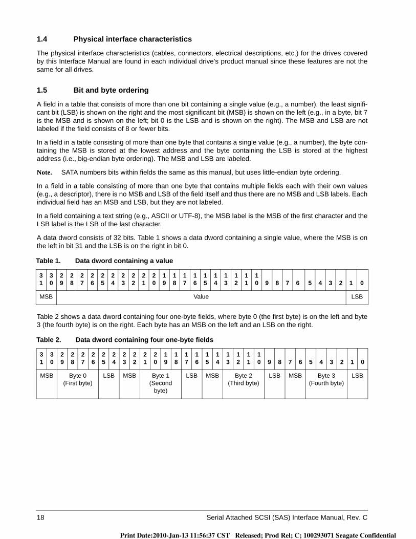
18 Serial Attached SCSI (SAS) Interface Manual, Rev. C
1.4 Physical interface characteristics
The physical interface characteristics (cables, connectors, electrical descriptions, etc.) for the drives covered by this Interface Manual are found in each individual drive’s product manual since these features are not the same for all drives.
1.5 Bit and byte ordering
A field in a table that consists of more than one bit containing a single value (e.g., a number), the least signifi-cant bit (LSB) is shown on the right and the most significant bit (MSB) is shown on the left (e.g., in a byte, bit 7 is the MSB and is shown on the left; bit 0 is the LSB and is shown on the right). The MSB and LSB are not labeled if the field consists of 8 or fewer bits.
In a field in a table consisting of more than one byte that contains a single value (e.g., a number), the byte con-taining the MSB is stored at the lowest address and the byte containing the LSB is stored at the highest address (i.e., big-endian byte ordering). The MSB and LSB are labeled.
Note. SATA numbers bits within fields the same as this manual, but uses little-endian byte ordering.
In a field in a table consisting of more than one byte that contains multiple fields each with their own values (e.g., a descriptor), there is no MSB and LSB of the field itself and thus there are no MSB and LSB labels. Each individual field has an MSB and LSB, but they are not labeled.
In a field containing a text string (e.g., ASCII or UTF-8), the MSB label is the MSB of the first character and the LSB label is the LSB of the last character.
A data dword consists of 32 bits. Table 1 shows a data dword containing a single value, where the MSB is on the left in bit 31 and the LSB is on the right in bit 0.
Table 2 shows a data dword containing four one-byte fields, where byte 0 (the first byte) is on the left and byte 3 (the fourth byte) is on the right. Each byte has an MSB on the left and an LSB on the right.
Table 1. Data dword containing a value
31
30
29
28
27
26
25
24
23
22
21
20
19
18
17
16
15
14
13
12
11
10 9 8 7 6 5 4 3 2 1 0
MSB Value LSB
Table 2. Data dword containing four one-byte fields
31
30
29
28
27
26
25
24
23
22
21
20
19
18
17
16
15
14
13
12
11
10 9 8 7 6 5 4 3 2 1 0
MSB Byte 0(First byte)
LSB MSB Byte 1(Second
byte)
LSB MSB Byte 2(Third byte)
LSB MSB Byte 3(Fourth byte)
LSB
Print Date:2010-Jan-13 11:56:37 CST Released; Prod Rel; C; 100293071 Seagate Confidential
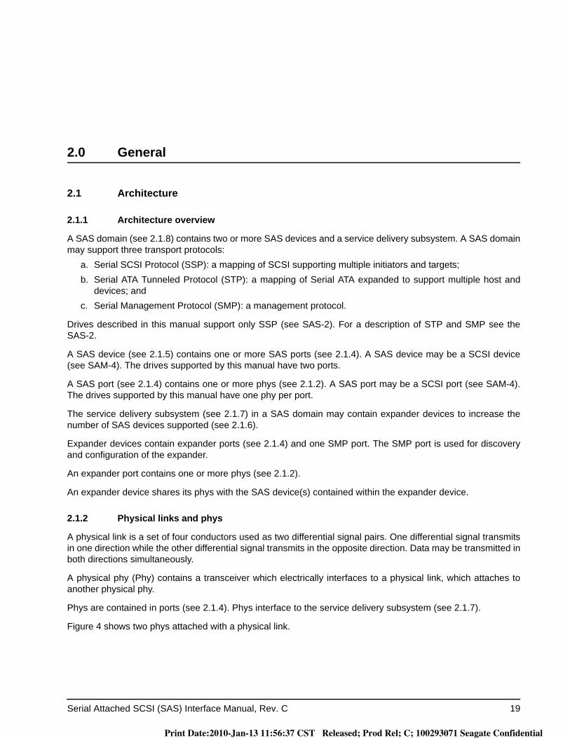
Serial Attached SCSI (SAS) Interface Manual, Rev. C 19
2.0 General
2.1 Architecture
2.1.1 Architecture overview
A SAS domain (see 2.1.8) contains two or more SAS devices and a service delivery subsystem. A SAS domain may support three transport protocols:
a. Serial SCSI Protocol (SSP): a mapping of SCSI supporting multiple initiators and targets;b. Serial ATA Tunneled Protocol (STP): a mapping of Serial ATA expanded to support multiple host and
devices; andc. Serial Management Protocol (SMP): a management protocol.
Drives described in this manual support only SSP (see SAS-2). For a description of STP and SMP see the SAS-2.
A SAS device (see 2.1.5) contains one or more SAS ports (see 2.1.4). A SAS device may be a SCSI device (see SAM-4). The drives supported by this manual have two ports.
A SAS port (see 2.1.4) contains one or more phys (see 2.1.2). A SAS port may be a SCSI port (see SAM-4). The drives supported by this manual have one phy per port.
The service delivery subsystem (see 2.1.7) in a SAS domain may contain expander devices to increase the number of SAS devices supported (see 2.1.6).
Expander devices contain expander ports (see 2.1.4) and one SMP port. The SMP port is used for discovery and configuration of the expander.
An expander port contains one or more phys (see 2.1.2).
An expander device shares its phys with the SAS device(s) contained within the expander device.
2.1.2 Physical links and phys
A physical link is a set of four conductors used as two differential signal pairs. One differential signal transmits in one direction while the other differential signal transmits in the opposite direction. Data may be transmitted in both directions simultaneously.
A physical phy (Phy) contains a transceiver which electrically interfaces to a physical link, which attaches to another physical phy.
Phys are contained in ports (see 2.1.4). Phys interface to the service delivery subsystem (see 2.1.7).
Figure 4 shows two phys attached with a physical link.
Print Date:2010-Jan-13 11:56:37 CST Released; Prod Rel; C; 100293071 Seagate Confidential
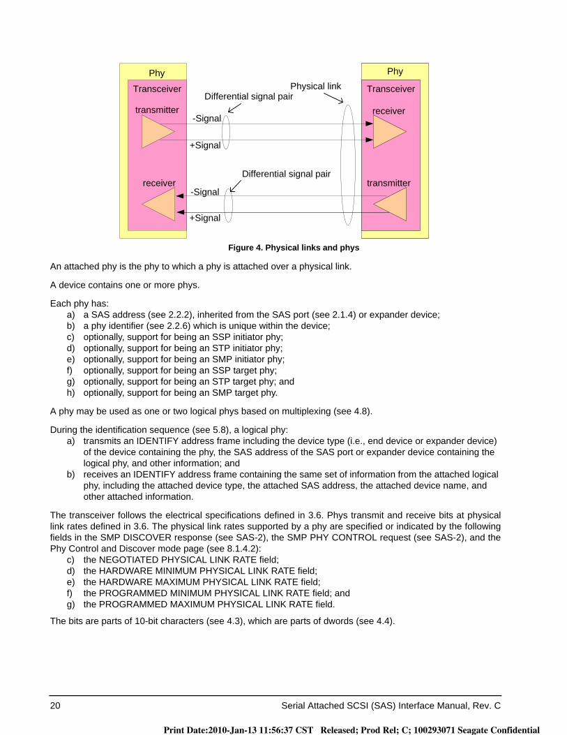
20 Serial Attached SCSI (SAS) Interface Manual, Rev. C
Figure 4. Physical links and phys
An attached phy is the phy to which a phy is attached over a physical link.
A device contains one or more phys.
Each phy has:a) a SAS address (see 2.2.2), inherited from the SAS port (see 2.1.4) or expander device;b) a phy identifier (see 2.2.6) which is unique within the device;c) optionally, support for being an SSP initiator phy;d) optionally, support for being an STP initiator phy;e) optionally, support for being an SMP initiator phy;f) optionally, support for being an SSP target phy;g) optionally, support for being an STP target phy; andh) optionally, support for being an SMP target phy.
A phy may be used as one or two logical phys based on multiplexing (see 4.8).
During the identification sequence (see 5.8), a logical phy:a) transmits an IDENTIFY address frame including the device type (i.e., end device or expander device)
of the device containing the phy, the SAS address of the SAS port or expander device containing the logical phy, and other information; and
b) receives an IDENTIFY address frame containing the same set of information from the attached logical phy, including the attached device type, the attached SAS address, the attached device name, and other attached information.
The transceiver follows the electrical specifications defined in 3.6. Phys transmit and receive bits at physical link rates defined in 3.6. The physical link rates supported by a phy are specified or indicated by the following fields in the SMP DISCOVER response (see SAS-2), the SMP PHY CONTROL request (see SAS-2), and the Phy Control and Discover mode page (see 8.1.4.2):
c) the NEGOTIATED PHYSICAL LINK RATE field;d) the HARDWARE MINIMUM PHYSICAL LINK RATE field;e) the HARDWARE MAXIMUM PHYSICAL LINK RATE field;f) the PROGRAMMED MINIMUM PHYSICAL LINK RATE field; andg) the PROGRAMMED MAXIMUM PHYSICAL LINK RATE field.
The bits are parts of 10-bit characters (see 4.3), which are parts of dwords (see 4.4).
TransceiverTransceiver
-Signal
+Signal
-Signal
+Signal
Phy Phy
Differential signal pair
Differential signal pair
Physical link
transmitter
transmitter
receiver
receiver
Print Date:2010-Jan-13 11:56:37 CST Released; Prod Rel; C; 100293071 Seagate Confidential

Serial Attached SCSI (SAS) Interface Manual, Rev. C 21
2.1.3 Logical links
A physical link with a physical link rate greater than 1.5 Gbps may be multiplexed into two logical links as defined in table 3.
Multiplexing is defined in 4.8.
2.1.4 Ports (narrow ports and wide ports)
A port contains one or more phys. Ports in a device are associated with physical phys based on the identifica-tion sequence.
A port is created from a set of physical phys if one or more physical phys contained within a device:a. transmit the same SAS address (see 2.2) during the identification sequence; andb. receive the same SAS address during the identification sequence (i.e., the corresponding attached phy
or phys transmit the same SAS address).
A port is a wide port if there is more than one phy in the port. A port is a narrow port if there is only one phy in the port.
A wide link is the set of physical links that attach a wide port to another wide port. A narrow link is the physical link that attaches a narrow port to another narrow port.
Attaching a phy within a wide port to another phy in the same port (i.e., the SAS address transmitted in the out-going IDENTIFY address frame is the same as the SAS address received in the incoming IDENTIFY address frame) is outside the scope of this manual.
Phys that are able to become part of the same wide port shall set the DEVICE TYPE field, the BREAK_REPLY CAPABLE bit, the SSP INITIATOR PORT bit, the STP INITIATOR PORT bit, the SMP INITIATOR PORT bit, the SSP TARGET PORT bit, the STP TARGET PORT bit, the SMP TARGET PORT bit, and the SAS ADDRESS field in the IDENTIFY address frame (see 5.7.2) transmitted during the identification sequence to the same set of values on each phy in the wide port. Recipient wide ports are not required to check the consis-tency of these fields across their phys.
Table 3. Logical links
Physical link rate Logical link(s)
6 GbpsOne 6 Gbps logical link
Two 3 Gbps logical links
3 GbpsOne 3 Gbps logical link
Two 1.5 Gbps logical links
1.5 Gbps One 1.5 Gbps logical link
Print Date:2010-Jan-13 11:56:37 CST Released; Prod Rel; C; 100293071 Seagate Confidential
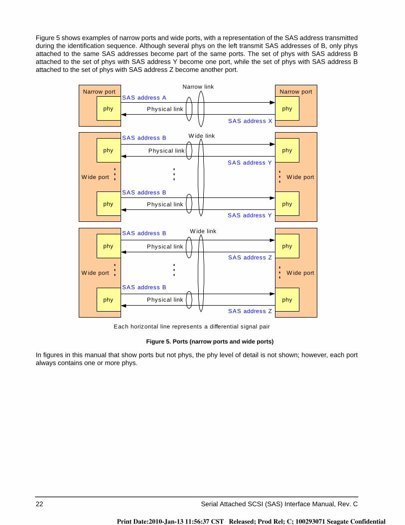
22 Serial Attached SCSI (SAS) Interface Manual, Rev. C
Figure 5 shows examples of narrow ports and wide ports, with a representation of the SAS address transmitted during the identification sequence. Although several phys on the left transmit SAS addresses of B, only phys attached to the same SAS addresses become part of the same ports. The set of phys with SAS address B attached to the set of phys with SAS address Y become one port, while the set of phys with SAS address B attached to the set of phys with SAS address Z become another port.
Figure 5. Ports (narrow ports and wide ports)
In figures in this manual that show ports but not phys, the phy level of detail is not shown; however, each port always contains one or more phys.
W ide portW ide port
phy phy
phy phy
Each horizontal line represents a differential s ignal pair
Physical link
Physical link
W ide link
Narrow portNarrow port
Physical linkphy phy
Narrow link
W ide portW ide port
phy phy
phy phy
Physical link
Physical link
W ide link
SAS address A
SAS address B
SAS address B
SAS address B
SAS address B
SAS address X
SAS address Y
SAS address Y
SAS address Z
SAS address Z
Print Date:2010-Jan-13 11:56:37 CST Released; Prod Rel; C; 100293071 Seagate Confidential
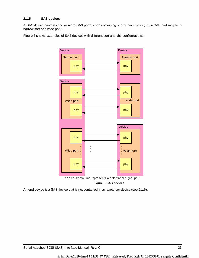
Serial Attached SCSI (SAS) Interface Manual, Rev. C 23
2.1.5 SAS devices
A SAS device contains one or more SAS ports, each containing one or more phys (i.e., a SAS port may be a narrow port or a wide port).
Figure 6 shows examples of SAS devices with different port and phy configurations.
Figure 6. SAS devices
An end device is a SAS device that is not contained in an expander device (see 2.1.6).
W ide port
W ide port
Narrow port
phy
phy
phy
phy
phy
Each horizontal line represents a differential s ignal pair
Device
Device
Narrow port
phy
W ide port
phy
phy
W ide port
phy
phy
Device
Device
Print Date:2010-Jan-13 11:56:37 CST Released; Prod Rel; C; 100293071 Seagate Confidential
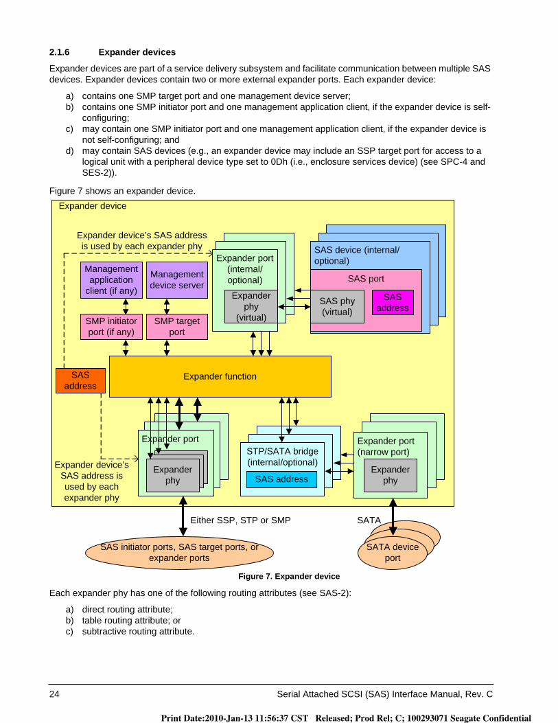
24 Serial Attached SCSI (SAS) Interface Manual, Rev. C
2.1.6 Expander devices
Expander devices are part of a service delivery subsystem and facilitate communication between multiple SAS devices. Expander devices contain two or more external expander ports. Each expander device:
a) contains one SMP target port and one management device server;b) contains one SMP initiator port and one management application client, if the expander device is self-
configuring;c) may contain one SMP initiator port and one management application client, if the expander device is
not self-configuring; andd) may contain SAS devices (e.g., an expander device may include an SSP target port for access to a
logical unit with a peripheral device type set to 0Dh (i.e., enclosure services device) (see SPC-4 and SES-2)).
Figure 7 shows an expander device.
Figure 7. Expander device
Each expander phy has one of the following routing attributes (see SAS-2):
a) direct routing attribute;b) table routing attribute; orc) subtractive routing attribute.
Expander device
Either SSP, STP or SMP
SAS initiator ports, SAS target ports, or expander ports
SATA
Expander port(narrow port)STP/SATA bridge
(internal/optional)Expander
phy
SATA device port
Expander function
SAS device (internal/optional)
SAS port
SAS phy (virtual)
SAS address
SAS address
SAS address
Expander port (internal/optional)
Expander phy
(virtual)
Expander port
Expander phy
Expander device’s SAS address is used by each expander phy
Expander device’s SAS address is used by each expander phy
Management application
client (if any)
Management device server
SMP target port
SMP initiator port (if any)
Print Date:2010-Jan-13 11:56:37 CST Released; Prod Rel; C; 100293071 Seagate Confidential
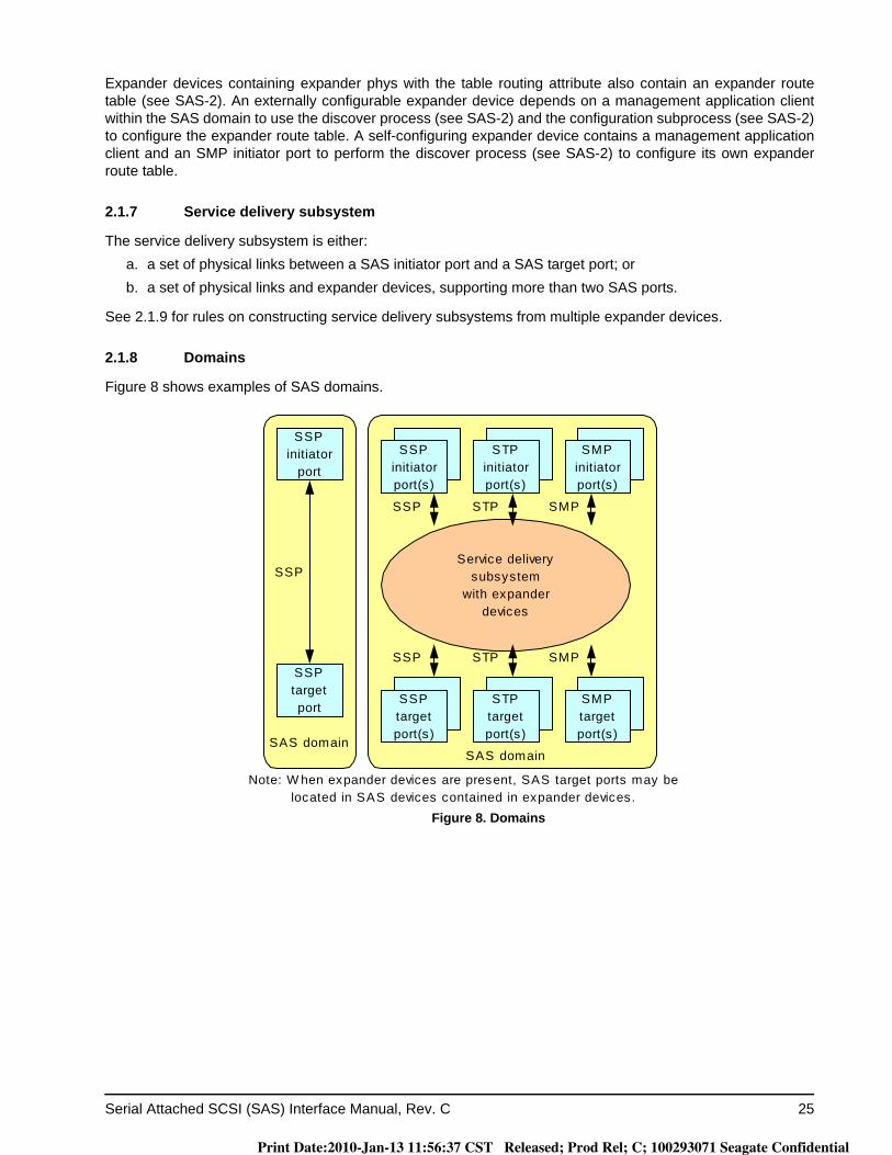
Serial Attached SCSI (SAS) Interface Manual, Rev. C 25
Expander devices containing expander phys with the table routing attribute also contain an expander route table (see SAS-2). An externally configurable expander device depends on a management application client within the SAS domain to use the discover process (see SAS-2) and the configuration subprocess (see SAS-2) to configure the expander route table. A self-configuring expander device contains a management application client and an SMP initiator port to perform the discover process (see SAS-2) to configure its own expander route table.
2.1.7 Service delivery subsystem
The service delivery subsystem is either:a. a set of physical links between a SAS initiator port and a SAS target port; orb. a set of physical links and expander devices, supporting more than two SAS ports.
See 2.1.9 for rules on constructing service delivery subsystems from multiple expander devices.
2.1.8 Domains
Figure 8 shows examples of SAS domains.
Figure 8. Domains
SSPinitiatorport(s)
SSPinitiator
port
SSPtargetport
SAS domainSAS domain
Service deliverysubsystem
with expanderdevices
SSP
SSP SMP
SSPinitiatorport(s)
SMPinitiatorport(s)
STPinitiatorport(s)
STP
SSPinitiatorport(s)
SSPtargetport(s)
SMPtargetport(s)
STPtargetport(s)
SSP SMPSTP
Note: W hen expander devices are present, SAS target ports may belocated in SAS devices contained in expander devices.
Print Date:2010-Jan-13 11:56:37 CST Released; Prod Rel; C; 100293071 Seagate Confidential
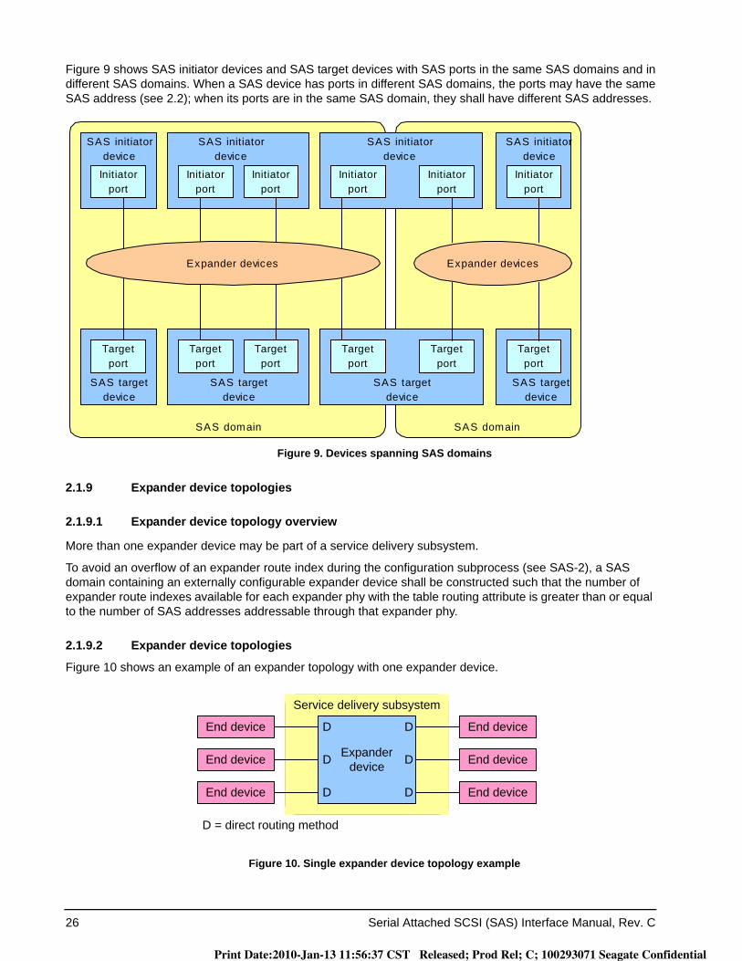
26 Serial Attached SCSI (SAS) Interface Manual, Rev. C
Figure 9 shows SAS initiator devices and SAS target devices with SAS ports in the same SAS domains and in different SAS domains. When a SAS device has ports in different SAS domains, the ports may have the same SAS address (see 2.2); when its ports are in the same SAS domain, they shall have different SAS addresses.
Figure 9. Devices spanning SAS domains
2.1.9 Expander device topologies
2.1.9.1 Expander device topology overview
More than one expander device may be part of a service delivery subsystem.
To avoid an overflow of an expander route index during the configuration subprocess (see SAS-2), a SAS domain containing an externally configurable expander device shall be constructed such that the number of expander route indexes available for each expander phy with the table routing attribute is greater than or equal to the number of SAS addresses addressable through that expander phy.
2.1.9.2 Expander device topologies
Figure 10 shows an example of an expander topology with one expander device.
Figure 10. Single expander device topology example
Initiatorport
SAS initiatordevice
SAS initiatordevice
SAS initiatordevice
Expander devices Expander devices
SAS initiatordevice
Initiatorport
Initiatorport
Initiatorport
Initiatorport
Initiatorport
Targetport
SAS targetdevice
SAS targetdevice
SAS targetdevice
SAS targetdevice
Targetport
Targetport
Targetport
Targetport
Targetport
SAS domain SAS domain
Expander device
Service delivery subsystem
End device
End device
End device
End device
D
D
D
D
End deviceEnd device D D
D = direct routing method
Print Date:2010-Jan-13 11:56:37 CST Released; Prod Rel; C; 100293071 Seagate Confidential
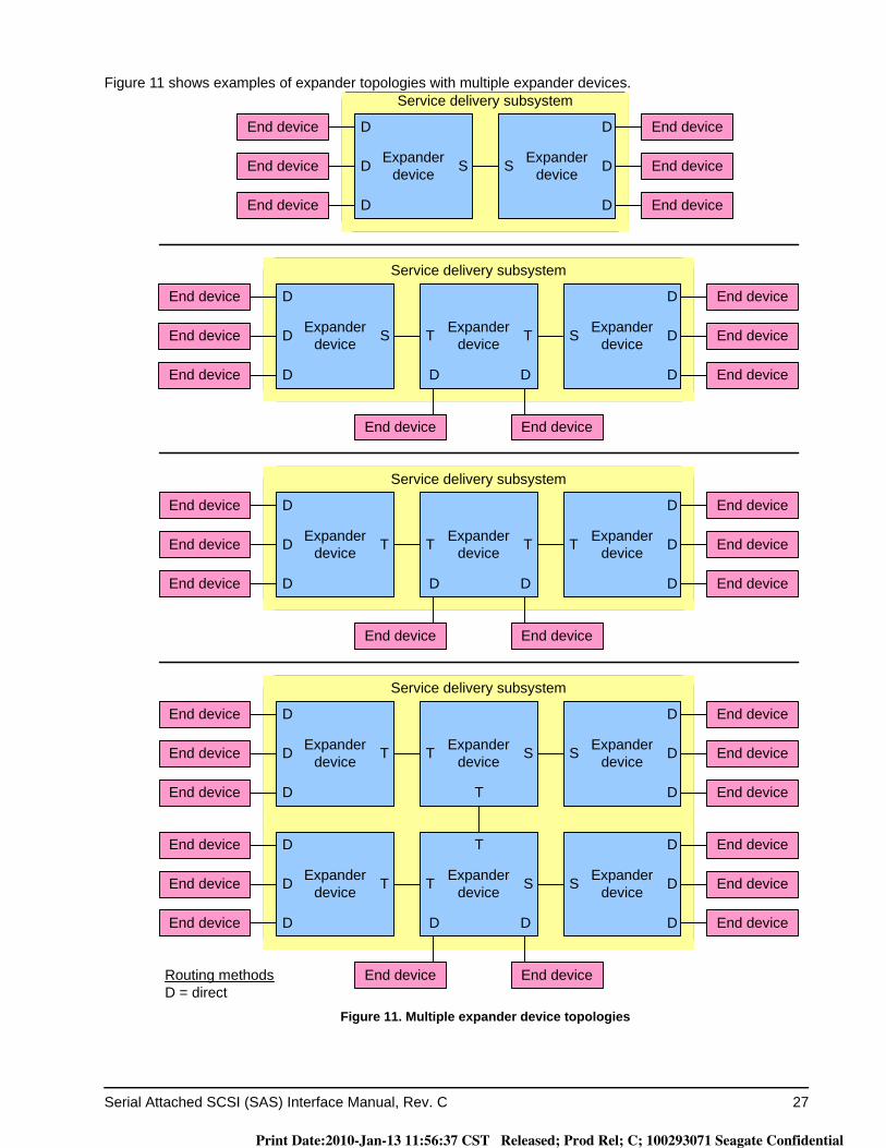
Serial Attached SCSI (SAS) Interface Manual, Rev. C 27
Figure 11 shows examples of expander topologies with multiple expander devices.
Figure 11. Multiple expander device topologies
Expander device
Service delivery subsystem
End device
End device
End device
End device
D
D
End deviceEnd device D
Expander device
Expander device
D
D
D
End device End device
S T T S
Expander device
Service delivery subsystem
End device
End device
End device
End device
D
D
End deviceEnd device D
Expander device
Expander device
D
D
D
End device End device
T T T T
Expander device
Service delivery subsystem
End device
End device
End device
End device
D
D
End deviceEnd device D
Expander device
Expander device
D
D
D
T T S S
Expander device
Expander device
Expander deviceT T S S
T End device
End device
End device
D
D
D
End device
End device
D
D
End device D
T
DD
End device End device
DD
Routing methodsD = direct
DD
Expander device
Service delivery subsystem
End device
End device
End device
End device
D
D
End deviceEnd device D
Expander device
D
D
D
S S
Print Date:2010-Jan-13 11:56:37 CST Released; Prod Rel; C; 100293071 Seagate Confidential
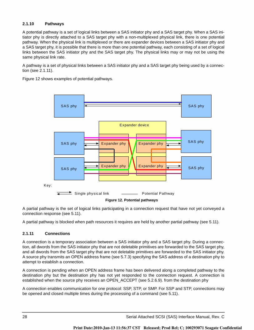
28 Serial Attached SCSI (SAS) Interface Manual, Rev. C
2.1.10 Pathways
A potential pathway is a set of logical links between a SAS initiator phy and a SAS target phy. When a SAS ini-tiator phy is directly attached to a SAS target phy with a non-multiplexed physical link, there is one potential pathway. When the physical link is multiplexed or there are expander devices between a SAS initiator phy and a SAS target phy, it is possible that there is more than one potential pathway, each consisting of a set of logical links between the SAS initiator phy and the SAS target phy. The physical links may or may not be using the same physical link rate.
A pathway is a set of physical links between a SAS initiator phy and a SAS target phy being used by a connec-tion (see 2.1.11).
Figure 12 shows examples of potential pathways.
Figure 12. Potential pathways
A partial pathway is the set of logical links participating in a connection request that have not yet conveyed a connection response (see 5.11).
A partial pathway is blocked when path resources it requires are held by another partial pathway (see 5.11).
2.1.11 Connections
A connection is a temporary association between a SAS initiator phy and a SAS target phy. During a connec-tion, all dwords from the SAS initiator phy that are not deletable primitives are forwarded to the SAS target phy, and all dwords from the SAS target phy that are not deletable primitives are forwarded to the SAS initiator phy. A source phy transmits an OPEN address frame (see 5.7.3) specifying the SAS address of a destination phy to attempt to establish a connection.
A connection is pending when an OPEN address frame has been delivered along a completed pathway to the destination phy but the destination phy has not yet responded to the connection request. A connection is established when the source phy receives an OPEN_ACCEPT (see 5.2.6.9). from the destination phy
A connection enables communication for one protocol: SSP, STP, or SMP. For SSP and STP, connections may be opened and closed multiple times during the processing of a command (see 5.11).
Single physical link
SAS phy
SAS phy
SAS phySAS phy
SAS phy
SAS phy
Expander device
Potential Pathway
Expander phy
Expander phy
Expander phy
Expander phy
Key:
Print Date:2010-Jan-13 11:56:37 CST Released; Prod Rel; C; 100293071 Seagate Confidential
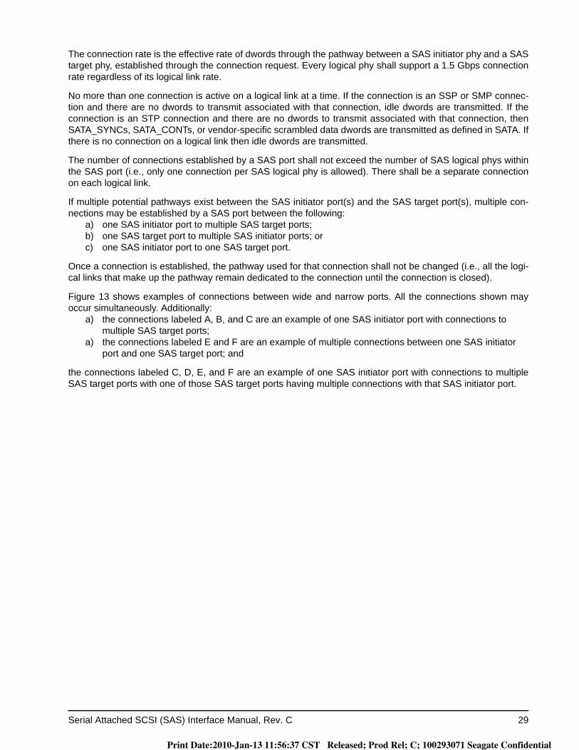
Serial Attached SCSI (SAS) Interface Manual, Rev. C 29
The connection rate is the effective rate of dwords through the pathway between a SAS initiator phy and a SAS target phy, established through the connection request. Every logical phy shall support a 1.5 Gbps connection rate regardless of its logical link rate.
No more than one connection is active on a logical link at a time. If the connection is an SSP or SMP connec-tion and there are no dwords to transmit associated with that connection, idle dwords are transmitted. If the connection is an STP connection and there are no dwords to transmit associated with that connection, then SATA_SYNCs, SATA_CONTs, or vendor-specific scrambled data dwords are transmitted as defined in SATA. If there is no connection on a logical link then idle dwords are transmitted.
The number of connections established by a SAS port shall not exceed the number of SAS logical phys within the SAS port (i.e., only one connection per SAS logical phy is allowed). There shall be a separate connection on each logical link.
If multiple potential pathways exist between the SAS initiator port(s) and the SAS target port(s), multiple con-nections may be established by a SAS port between the following:
a) one SAS initiator port to multiple SAS target ports;b) one SAS target port to multiple SAS initiator ports; orc) one SAS initiator port to one SAS target port.
Once a connection is established, the pathway used for that connection shall not be changed (i.e., all the logi-cal links that make up the pathway remain dedicated to the connection until the connection is closed).
Figure 13 shows examples of connections between wide and narrow ports. All the connections shown may occur simultaneously. Additionally:
a) the connections labeled A, B, and C are an example of one SAS initiator port with connections to multiple SAS target ports;
a) the connections labeled E and F are an example of multiple connections between one SAS initiator port and one SAS target port; and
the connections labeled C, D, E, and F are an example of one SAS initiator port with connections to multiple SAS target ports with one of those SAS target ports having multiple connections with that SAS initiator port.
Print Date:2010-Jan-13 11:56:37 CST Released; Prod Rel; C; 100293071 Seagate Confidential
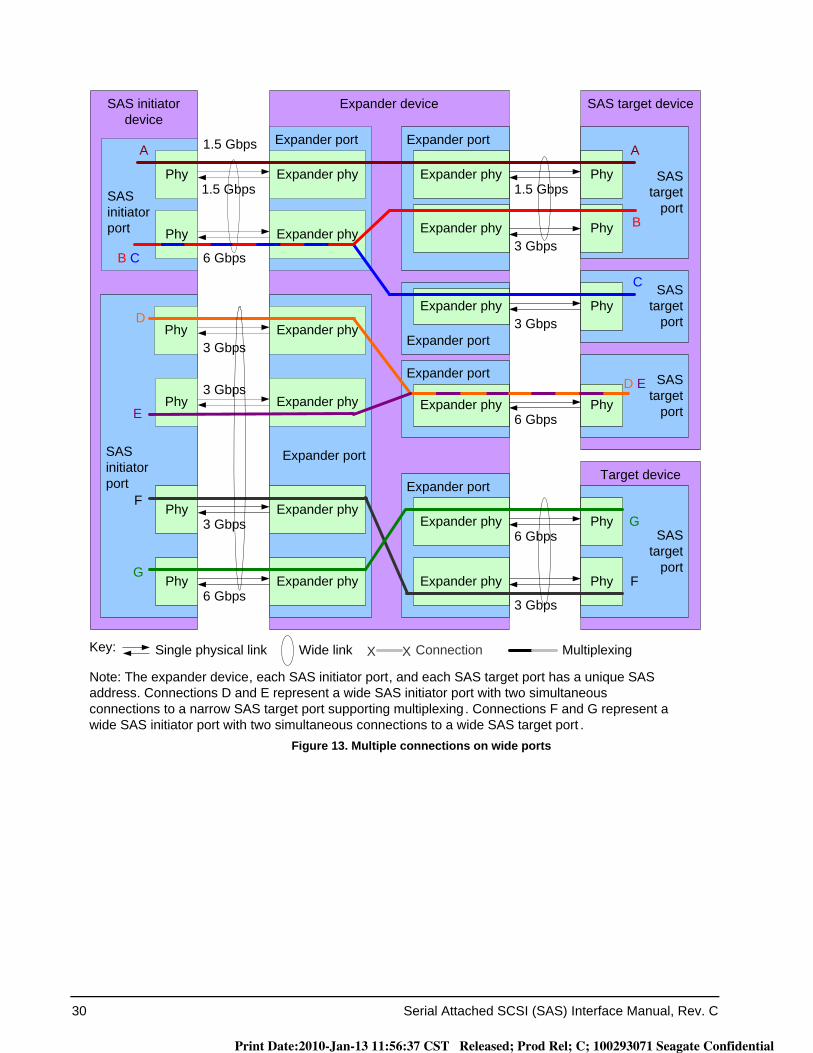
30 Serial Attached SCSI (SAS) Interface Manual, Rev. C
Figure 13. Multiple connections on wide ports
Target device
SAS initiator device
SAS target device
SAStarget
port
Expander device
SASinitiatorport
Single physical link
SAStarget
port
SAStarget
port
SAS initiatorport
Expander port
Expander port
Expander port
SAStarget
port
Expander port
Expander port
Expander port
E
D
B C
A
G
F
D E
B
C
A
G
F
Phy
Phy
Phy
Phy
Phy
Phy
Phy
Phy
Phy
Phy
Phy
Phy
Expander phy Expander phy
Expander phy
Expander phy
Expander phy
Expander phy
Expander phy Expander phy
Expander phy
Expander phy Expander phy
Expander phy
Key:
Note: The expander device, each SAS initiator port, and each SAS target port has a unique SAS address. Connections D and E represent a wide SAS initiator port with two simultaneous connections to a narrow SAS target port supporting multiplexing. Connections F and G represent a wide SAS initiator port with two simultaneous connections to a wide SAS target port .
Wide link ConnectionX X
1.5 Gbps
6 Gbps3 Gbps
3 Gbps
1.5 Gbps 1.5 Gbps
3 Gbps
3 Gbps
6 Gbps
3 Gbps
6 Gbps
6 Gbps
3 Gbps
Multiplexing
Print Date:2010-Jan-13 11:56:37 CST Released; Prod Rel; C; 100293071 Seagate Confidential

Serial Attached SCSI (SAS) Interface Manual, Rev. C 31
2.2 Names and identifiers
2.2.1 Names and identifiers
Four SAS addresses are allocated for each drive.a. The drive has a general SAS address that does not refer to a port but to SAS device address. This is
stored in inquiry vital product page 83h (see the SCSI Commands Reference Manual).b. Port A has a unique SAS address. This is used for any identify or open address frames transmitted from
this port.c. Port B has a unique SAS address. This is used for any identify or open address frames transmitted from
this port.d. The drive has a SAS address for the single LUN supported in the drive.
2.2.2 SAS addresses
Table 4 defines the SAS address format. SAS addresses shall be compatible with the NAA (Name Address Authority) IEEE Registered format identification descriptor.
NAA field
The NAA field contains 5h.
IEEE COMAPNY ID field
The IEEE COMAPNY ID field contains a 24-bit canonical form company identifier assigned by the IEEE. Information about IEEE company identifiers may be obtained from the http://s.ieee.org/regauth/oui web site.
Table 4. SAS address format
Byte\Bit 7 6 5 4 3 2 1 0
0 NAA (5h) (MSB)
1IEEE COMAPNY ID
2
3 (LSB) (MSB)
4
VENDOR SPECIFIC IDENTIFIER5
6
7 (LSB)
Print Date:2010-Jan-13 11:56:37 CST Released; Prod Rel; C; 100293071 Seagate Confidential
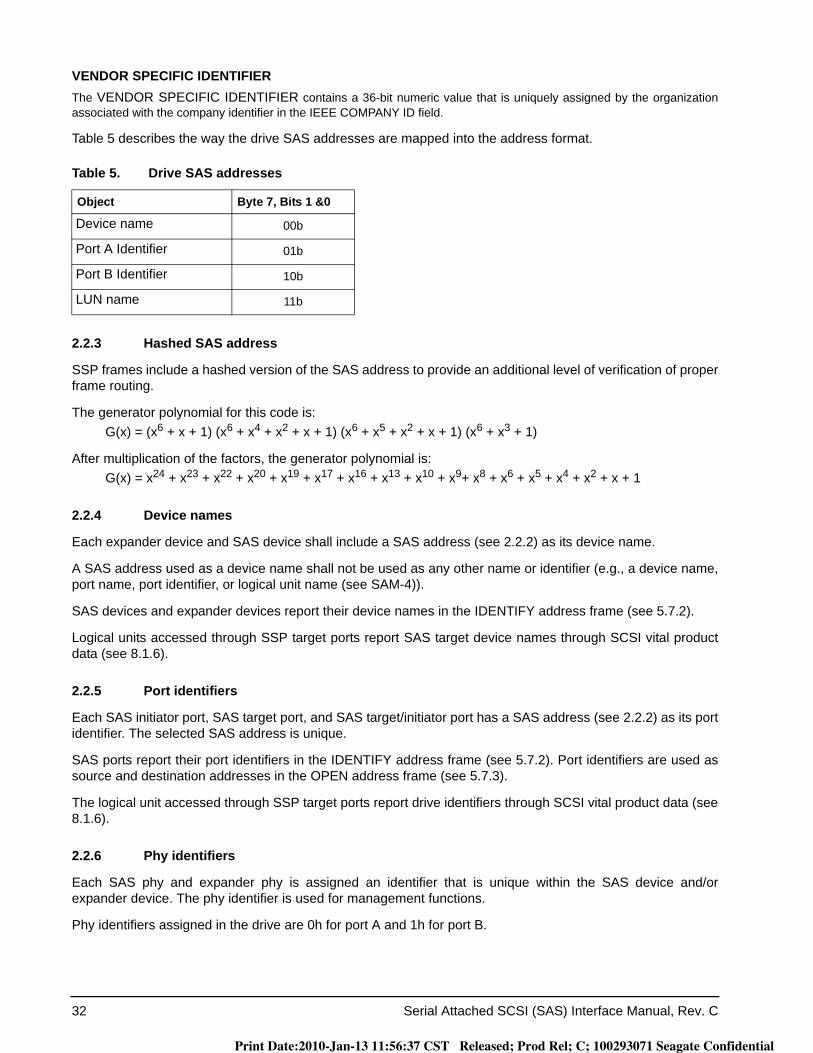
32 Serial Attached SCSI (SAS) Interface Manual, Rev. C
VENDOR SPECIFIC IDENTIFIERThe VENDOR SPECIFIC IDENTIFIER contains a 36-bit numeric value that is uniquely assigned by the organization associated with the company identifier in the IEEE COMPANY ID field.
Table 5 describes the way the drive SAS addresses are mapped into the address format.
2.2.3 Hashed SAS address
SSP frames include a hashed version of the SAS address to provide an additional level of verification of proper frame routing.
The generator polynomial for this code is:G(x) = (x6 + x + 1) (x6 + x4 + x2 + x + 1) (x6 + x5 + x2 + x + 1) (x6 + x3 + 1)
After multiplication of the factors, the generator polynomial is:G(x) = x24 + x23 + x22 + x20 + x19 + x17 + x16 + x13 + x10 + x9+ x8 + x6 + x5 + x4 + x2 + x + 1
2.2.4 Device names
Each expander device and SAS device shall include a SAS address (see 2.2.2) as its device name.
A SAS address used as a device name shall not be used as any other name or identifier (e.g., a device name, port name, port identifier, or logical unit name (see SAM-4)).
SAS devices and expander devices report their device names in the IDENTIFY address frame (see 5.7.2).
Logical units accessed through SSP target ports report SAS target device names through SCSI vital product data (see 8.1.6).
2.2.5 Port identifiers
Each SAS initiator port, SAS target port, and SAS target/initiator port has a SAS address (see 2.2.2) as its port identifier. The selected SAS address is unique.
SAS ports report their port identifiers in the IDENTIFY address frame (see 5.7.2). Port identifiers are used as source and destination addresses in the OPEN address frame (see 5.7.3).
The logical unit accessed through SSP target ports report drive identifiers through SCSI vital product data (see 8.1.6).
2.2.6 Phy identifiers
Each SAS phy and expander phy is assigned an identifier that is unique within the SAS device and/or expander device. The phy identifier is used for management functions.
Phy identifiers assigned in the drive are 0h for port A and 1h for port B.
Table 5. Drive SAS addresses
Object Byte 7, Bits 1 &0
Device name 00b
Port A Identifier 01b
Port B Identifier 10b
LUN name 11b
Print Date:2010-Jan-13 11:56:37 CST Released; Prod Rel; C; 100293071 Seagate Confidential
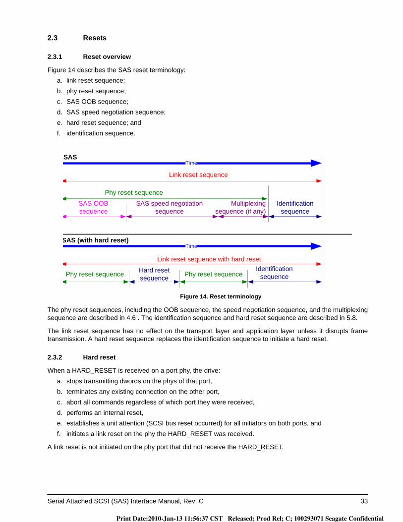
Serial Attached SCSI (SAS) Interface Manual, Rev. C 33
2.3 Resets
2.3.1 Reset overview
Figure 14 describes the SAS reset terminology:a. link reset sequence;b. phy reset sequence;c. SAS OOB sequence;d. SAS speed negotiation sequence;e. hard reset sequence; andf. identification sequence.
Figure 14. Reset terminology
The phy reset sequences, including the OOB sequence, the speed negotiation sequence, and the multiplexing sequence are described in 4.6 . The identification sequence and hard reset sequence are described in 5.8.
The link reset sequence has no effect on the transport layer and application layer unless it disrupts frame transmission. A hard reset sequence replaces the identification sequence to initiate a hard reset.
2.3.2 Hard reset
When a HARD_RESET is received on a port phy, the drive:a. stops transmitting dwords on the phys of that port,b. terminates any existing connection on the other port,c. abort all commands regardless of which port they were received,d. performs an internal reset,e. establishes a unit attention (SCSI bus reset occurred) for all initiators on both ports, andf. initiates a link reset on the phy the HARD_RESET was received.
A link reset is not initiated on the phy port that did not receive the HARD_RESET.
Identification sequence
SAS OOB sequence
Link reset sequence
SAS
SAS speed negotiation sequence
Time
Phy reset sequence
Hard resetsequence
Link reset sequence with hard reset
Time
Phy reset sequence
SAS (with hard reset)
Multiplexing sequence (if any)
Identification sequencePhy reset sequence
Print Date:2010-Jan-13 11:56:37 CST Released; Prod Rel; C; 100293071 Seagate Confidential
34 Serial Attached SCSI (SAS) Interface Manual, Rev. C
2.4 I_T nexus loss
When a SAS port receives OPEN_REJECT (NO DESTINATION), OPEN_REJECT (PATHWAY BLOCKED), OPEN_REJECT (RESERVED INITIALIZE 0), OPEN_REJECT (RESERVED INITIALIZE 1), OPEN_REJECT (RESERVED STOP 0), OPEN_REJECT (RESERVED STOP 1), or an Open Timeout timer expires (see 5.11.2)in response to a connection request, it shall retry the connection request until:
a. the connection is established; orb. for SSP target ports, the time indicated by the I_T_NEXUS LOSS field in the Protocol-Specific Port Con-
trol mode page expires (see 8.1.4).
If the time expires, then the drive sends a Nexus Lost event notification to the SCSI application layer; the SCSI device shall perform the actions defined for I_T nexus loss in SAM-4.
Print Date:2010-Jan-13 11:56:37 CST Released; Prod Rel; C; 100293071 Seagate Confidential

Serial Attached SCSI (SAS) Interface Manual, Rev. C 35
2.5 Phy power conditions
2.5.1 Low phy power conditions
2.5.1.1 Low phy power conditions overview
Low phy power conditions shall only be enabled on phys if multiplexing (see 4.8) and optical mode are dis-abled.
If the partial phy power condition is enabled and the received IDENTIFY address frame has the PARTIAL CAPABLE bit set to one (see 5.7.2), then phys may generate PS_REQ (PARTIAL). If the slumber phy power condition is enabled and the received IDENTIFY address frame has the SLUMBER CAPABLE bit set to one (see 5.7.2), then phys may generate PS_REQ (SLUMBER). If low phy power conditions are enabled, then phys may reply with PS_ACK to accept a low phy power condition request. If low phy power conditions are supported and disabled, then phys shall reject a low phy power condition request by replying with PS_NAK.
If a SAS phy or expander phy is in a low phy power condition and that phy is requested to transmit a NOTIFY, then the NOTIFY shall not be transmitted and that phy shall remain in the same low phy power condition.
2.5.1.2 SAS low phy power conditions
Low phy power conditions may be enabled in SAS target devices using the Enhanced Phy Control mode page (see the SCSI Commnads Reference manual).
The management application client layer shall not enable low phy power conditions until after receiving a Phy Power Condition Status (Enable Low Phy Power Conditions) confirmation from the SA_PC state machine (see SPL).
If a SAS phy is in a low phy power condition, then to originate a Broadcast the application layer:1) shall initiate the exit power condition procedure (see 4.6.4.1) on that SAS phy;2) shall originate the Broadcast; and3) may initiate the procedure to return that SAS phy to a low phy power condition.
2.5.1.3 Expander low phy power conditions
Low phy power conditions may be enabled in SAS expander devices using the SMP PHY CONTROL function (see SPL).
2.5.1.4 Active phy power condition
While in the active phy power condition:a) a phy is capable of transmitting information and responding to received information without changing
that phy’s power condition; andb) the phy may consume more power than when the phy is in a low phy power condition.
2.5.1.5 Partial phy power condition
While in the partial phy power condition:a) a phy is only capable of processing a COMINIT or COMWAKE;b) a phy may take less time to return to the active phy power condition (see table 50) than when in the
slumber phy power condition; andc) the power consumed by the phy should be less than or equal to the power consumed when the phy is
in the active phy power condition and may be greater than the power consumed when the phy is in the slumber phy power condition.
Print Date:2010-Jan-13 11:56:37 CST Released; Prod Rel; C; 100293071 Seagate Confidential
36 Serial Attached SCSI (SAS) Interface Manual, Rev. C
2.5.1.6 Slumber phy power condition
While in the slumber phy power condition:a) a phy is only capable of processing a COMINIT or COMWAKE;b) a phy may take more time to return to the active phy power condition (see table 50) than when in the
partial phy power condition; andc) the power consumed by the phy should be less than the power consumed when the phy is in the active
phy power condition or when the phy is in the partial phy power condition.
2.5.2 SCSI phy power conditions
SCSI idle and standby power conditions, implemented with the START STOP UNIT command (see the SCSI Commnads Reference manual) and the Power Condition mode page (see the SCSI Commnads Reference manual), may be supported by SSP initiator ports and SSP target ports as described in 8.1.7.
2.5.3 SATA phy power conditions
See SPL for STP power conditions definition.
Print Date:2010-Jan-13 11:56:37 CST Released; Prod Rel; C; 100293071 Seagate Confidential
Serial Attached SCSI (SAS) Interface Manual, Rev. C 37
2.6 Phy test functions
2.6.1 Phy test functions overview
Phy test functions (e.g., transmission of test patterns) are used for phy and interconnect characterization and diagnosis. The phy may be attached to test equipment while performing a phy test function. The following optional mechanisms are defined for invoking phy test functions:
a) the Protocol-Specific diagnostic page for SAS (see the SCSI Commands Reference Manual) invokes a phy test function in a selected phy other than the phy that receives the diagnostic page in a SAS target device with an SSP target port. The SEND DIAGNOSTIC command (see the SCSI Commands Reference Manual) may be sent through any SSP target port to any logical unit in the SAS target device that contains the phy that is to perform the phy test function. The phy test function starts some time after the SSP target port receives an ACK for the RESPONSE frame transmitted in response to the SEND DIAGNOSTIC command; and
b) the SMP PHY TEST FUNCTION function (see SAS-2) invokes a phy test function in a phy controlled by a management device server other than the phy that receives the function. The phy test function starts some time after the SMP target port transmits the SMP response frame.
Each phy test function is optional.
If the phy test function requires a specific phy test pattern and/or phy test function physical link rate, then the mechanism for invoking the phy test function also specifies the phy test pattern and phy test function physical link rate.
The phy test function on one phy may affect the previously negotiated settings on other phys (e.g., in a device with a common SSC clock, the SSC modulation type may change from none to down-spreading even on phys that negotiated no SSC).
While a phy is performing a phy test function, the link layer receivers shall ignore all incoming dwords and the OOB signal detector shall detect COMINIT. The phy shall ignore any other OOB signals (i.e., COMSAS and COMWAKE).
A phy stops performing a phy test function:a) after the SCSI device server, if any, processes a Protocol-Specific diagnostic page specifying the phy
and specifying a phy test function of 00h (i.e., STOP);b) after the management device server, if any, processes an SMP PHY TEST FUNCTION request speci-
fying the phy and specifying a phy test function of 00h (i.e., STOP);c) after the phy receives COMINIT; ord) upon power off.
It is vendor-specific how long a phy takes to stop performing the phy test function. After a phy stops performing a phy test function, it performs a link reset sequence.
2.6.2 Transmit pattern phy test function
While a phy is performing the transmit pattern phy test function, the test equipment attached to that phy:a) shall not transmit COMSAS or COMWAKE; andb) shall not transmit COMINIT except to stop the phy test function.
While performing the transmit pattern phy test function, a phy:a) shall ignore all dwords received; andb) shall repeatedly transmit the specified pattern at the specified physical link rate.
Print Date:2010-Jan-13 11:56:37 CST Released; Prod Rel; C; 100293071 Seagate Confidential
38 Serial Attached SCSI (SAS) Interface Manual, Rev. C
2.7 Phy events
Phys shall count the following events using saturating counters and report them in the Protocol-Specific Port log page (see the SCSI Commands Reference Manual) and/or the SMP REPORT PHY ERROR LOG function (see SAS-2):
a) invalid dwords received;b) dwords received with running disparity errors;c) loss of dword synchronization; andd) phy reset problems.
The saturating counters are each up to 4 bytes wide.
Phys may count those events and certain other events (e.g., elasticity buffer overflows) using wrapping coun-ters and record peak values for certain events (e.g., the longest connection time) using peak value detectors, reporting them in the Protocol-Specific Port log page (see the SCSI Commands Reference Manual), SMP REPORT PHY EVENT function (see SAS-2), and/or the SMP REPORT PHY EVENT LIST function (see SAS-2). The wrapping counters and peak value detectors are each 4 bytes wide. Peak value detectors trigger Broadcast (Expander) under certain circumstances (see 5.2.6.3).
For phys not controlled by SMP target ports, the number of additional events monitored and which events to monitor is vendor-specific.
For phys controlled by SMP target ports, the number of additional events that are simultaneously monitored is vendor-specific, but the SMP CONFIGURE PHY EVENT function (see SAS-2) allows for specification of the events to monitor.
The management device server shall maintain phy events for the last vendor-specific number of events and should maintain at least one phy event per phy. The management device server shall assign descriptors to the events sequentially starting at 0001h and shall return the descriptors in the SMP REPORT PHY EVENT LIST response (see SAS-2). The management device server shall return the index of the descriptor for the last phy event in the SMP REPORT GENERAL response (see SAS-2), the SMP REPORT PHY EVENT LIST response (see SAS-2), and the SMP DISCOVER LIST response (see SAS-2). The management device server shall wrap the index to 0001h when the highest supported descriptor index has been used.
The management device server shall support phy event list descriptor (see the SCSI Commands Reference Manual) indexes from 0001h to FFFFh. The actual number of phy event list descriptors that the management device server maintains for retrieval with the REPORT PHY EVENT LIST request is vendor specific and is indi-cated by the MAXIMUM NUMBER OF STORED PHY EVENT LIST DESCRIPTORS field defined in the REPORT GENERAL response (see the SCSI Commands Reference Manual). The volatility of these stored descriptors is vendor specific. The management device server shall replace the oldest phy event list descriptor with a new one once the number of recorded descriptors exceeds the value indicated by the MAXIMUM NUM-BER OF STORED PHY EVENT LIST DESCRIPTORS field.
Print Date:2010-Jan-13 11:56:37 CST Released; Prod Rel; C; 100293071 Seagate Confidential

Serial Attached SCSI (SAS) Interface Manual, Rev. C 39
The PHY EVENT SOURCE field, defined in table 6, is used in the Protocol-Specific Port log page, the REPORT PHY EVENT function, the REPORT PHY EVENT LIST function, and the CONFIGURE PHY EVENT function (see the SCSI Commands Reference Manual) and indicates or specifies the type of phy event in the accompanying PHY EVENT field.
Table 6. PHY EVENT SOURCE field
Code Name Typea Description
00h No event N/A No event. The PHY EVENT field is not valid.
Phy layer-based phy events (01h to 1Fh)
01h Invalid dword count b WC Number of invalid dwords that have been received outside of phy reset sequences.
02h Running disparity error count b
WC Number of dwords containing running disparity errors that have been received outside of phy reset sequences.
03h Loss of dword synchroniza-tion count b
WC Number of times the phy has restarted the link reset sequence because it lost dword synchronization.
04h Phy reset problem count b WC Number of times a phy reset problem has occurred (see 4.6.2.2.4).
05h Elasticity buffer overflow count
WC Number of times the phy’s elasticity buffer (see 5.3) has overflowed outside of phy reset sequences (e.g., because it did not receive a suf-ficient number of deletable primitives).
06h Received ERROR count WC Number of times the phy received an ERROR primitive.
07h to 1Fh
Reserved for phy layer-based phy events
SAS arbitration-related phy events (20h to 3Fh)
20h Received address frame error count
WC Number of times the phy detected an invalid address frame (see 5.7) (e.g., because of a CRC error).
21h Transmitted abandon-class OPEN_REJECT count
WC Number of times the phy received an OPEN address frame and trans-mitted an abandon-class OPEN_REJECT (see 5.2.6.10). In expander devices, forwarded OPEN_REJECTs shall not be counted.
22h Received abandon-class OPEN_REJECT count
WC Number of times the phy originated an OPEN address frame and received an abandon-class OPEN_REJECT (see 5.2.6.10). In expander devices, OPEN_REJECTs in response to forwarded OPEN address frames shall not be counted.
23h Transmitted retry-class OPEN_REJECT count
WC Number of times the phy received an OPEN address frame and trans-mitted a retry-class OPEN_REJECT (see 5.2.6.10). In expander devices, forwarded OPEN_REJECTs shall not be counted.
24h Received retry-class OPEN_REJECT count
WC Number of times the phy originated an OPEN address frame and received a retry-class OPEN_REJECT (see 5.2.6.10). In expander devices, OPEN_REJECTs in response to forwarded OPEN address frames shall not be counted.
a The Type column indicates the source type:a) WC = wrapping counter;b) PVD = peak value detector; andc) N/A = not applicable.
b The SCSI Commands Reference Manual defines a saturating counter that counts this event.
Print Date:2010-Jan-13 11:56:37 CST Released; Prod Rel; C; 100293071 Seagate Confidential

40 Serial Attached SCSI (SAS) Interface Manual, Rev. C
25h Received AIP (WAITING ON PARTIAL) count
WC Number of times the phy received an AIP (WAITING ON PARTIAL) or AIP (RESERVED WAITING ON PARTIAL). In expander devices, for-warded AIPs shall be counted.
26h Received AIP (WAITING ON CONNECTION) count
WC Number of times the phy received an AIP (WAITING ON CONNEC-TION). In expander devices, forwarded AIPs shall be counted.
27h Transmitted BREAK count WC Number of times the phy transmitted a BREAK that was not a response to a BREAK it received (e.g., a Close Timeout was detected interfacing to the SMP target port).
28h Received BREAK count WC Number of times the phy received a BREAK that was not a response to a BREAK that it transmitted.
29h Break Timeout count WC Number of times the phy transmitted a BREAK and did not receive a BREAK or BREAK_REPLY in response (e.g., as detected interfacing to the SMP target port).
2Ah Connection count WC Number of connections in which the phy was involved.
2Bh Peak transmitted pathway blocked count
PVD Peak value of a PATHWAY BLOCKED COUNT field in an OPEN address frame transmitted by the phy. Since the maximum value of the PATHWAY BLOCKED COUNT field is FFh, only byte 3 of the PHY EVENT field is used.
2Ch Peak transmitted arbitration wait time
PVD Peak value of an ARBITRATION WAIT TIME field in an OPEN address frame transmitted by the phy. Since the maximum value of the ARBITRATION WAIT TIME field is FFFFh, only byte 2 and byte 3 of the PHY EVENT field are used.
2Dh Peak arbitration time PVD Peak time in microseconds after transmitting an OPEN address frame that the phy has waited for connection response (e.g., OPEN_ACCEPT or OPEN_REJECT).
2Eh Peak connection time PVD The peak duration, in microseconds, of any connection in which the phy was involved.
2Fh to 3Fh
Reserved for SAS arbitration-related phy information
SSP-related phy events (40h to 4Fh)
40h Transmitted SSP frame count
WC Number of SSP frames transmitted.
41h Received SSP frame count WC Number of SSP frames received.
42h Transmitted SSP frame error count
WC Number of times the phy was used in a connection involving the SSP target port, transmitted an SSP frame, and received a NAK or an ACK/NAK timeout.
Table 6. PHY EVENT SOURCE field
Code Name Typea Description
a The Type column indicates the source type:a) WC = wrapping counter;b) PVD = peak value detector; andc) N/A = not applicable.
b The SCSI Commands Reference Manual defines a saturating counter that counts this event.
Print Date:2010-Jan-13 11:56:37 CST Released; Prod Rel; C; 100293071 Seagate Confidential
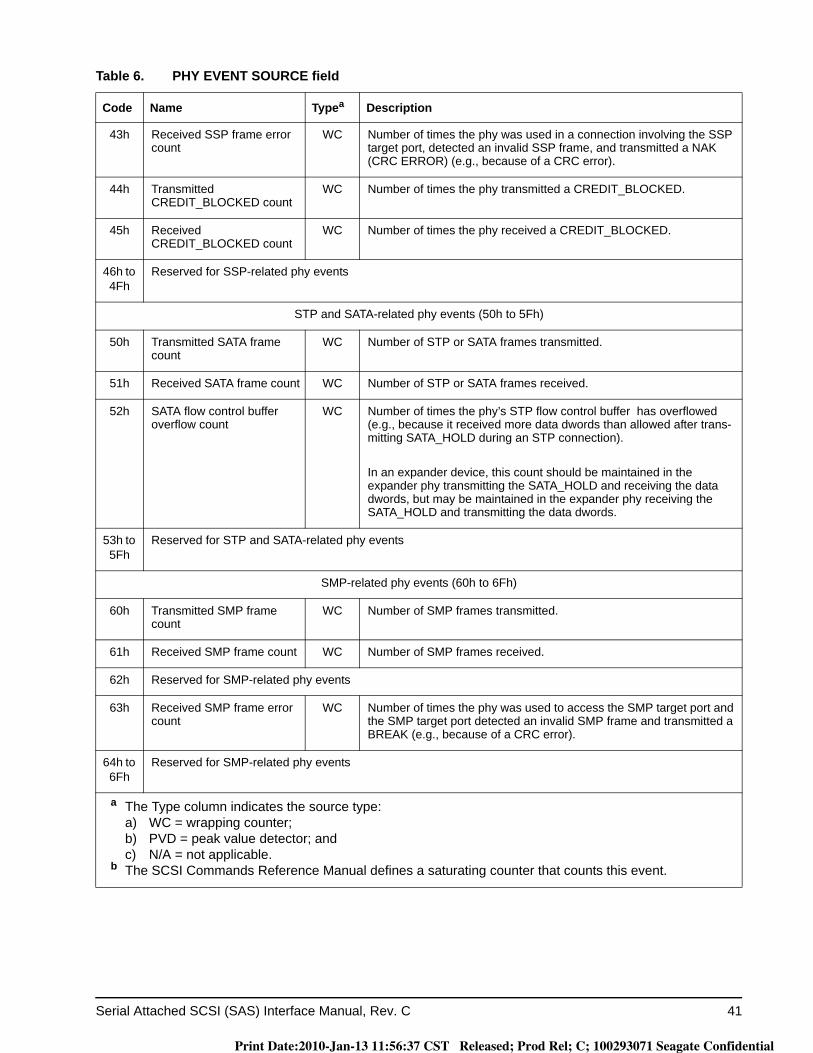
Serial Attached SCSI (SAS) Interface Manual, Rev. C 41
43h Received SSP frame error count
WC Number of times the phy was used in a connection involving the SSP target port, detected an invalid SSP frame, and transmitted a NAK (CRC ERROR) (e.g., because of a CRC error).
44h Transmitted CREDIT_BLOCKED count
WC Number of times the phy transmitted a CREDIT_BLOCKED.
45h Received CREDIT_BLOCKED count
WC Number of times the phy received a CREDIT_BLOCKED.
46h to 4Fh
Reserved for SSP-related phy events
STP and SATA-related phy events (50h to 5Fh)
50h Transmitted SATA frame count
WC Number of STP or SATA frames transmitted.
51h Received SATA frame count WC Number of STP or SATA frames received.
52h SATA flow control buffer overflow count
WC Number of times the phy’s STP flow control buffer has overflowed (e.g., because it received more data dwords than allowed after trans-mitting SATA_HOLD during an STP connection).
In an expander device, this count should be maintained in the expander phy transmitting the SATA_HOLD and receiving the data dwords, but may be maintained in the expander phy receiving the SATA_HOLD and transmitting the data dwords.
53h to 5Fh
Reserved for STP and SATA-related phy events
SMP-related phy events (60h to 6Fh)
60h Transmitted SMP frame count
WC Number of SMP frames transmitted.
61h Received SMP frame count WC Number of SMP frames received.
62h Reserved for SMP-related phy events
63h Received SMP frame error count
WC Number of times the phy was used to access the SMP target port and the SMP target port detected an invalid SMP frame and transmitted a BREAK (e.g., because of a CRC error).
64h to 6Fh
Reserved for SMP-related phy events
Table 6. PHY EVENT SOURCE field
Code Name Typea Description
a The Type column indicates the source type:a) WC = wrapping counter;b) PVD = peak value detector; andc) N/A = not applicable.
b The SCSI Commands Reference Manual defines a saturating counter that counts this event.
Print Date:2010-Jan-13 11:56:37 CST Released; Prod Rel; C; 100293071 Seagate Confidential

42 Serial Attached SCSI (SAS) Interface Manual, Rev. C
Other (70h to FFh)
70h to CFh
Reserved
D0h to FFh
Vendor specific
Table 6. PHY EVENT SOURCE field
Code Name Typea Description
a The Type column indicates the source type:a) WC = wrapping counter;b) PVD = peak value detector; andc) N/A = not applicable.
b The SCSI Commands Reference Manual defines a saturating counter that counts this event.
Print Date:2010-Jan-13 11:56:37 CST Released; Prod Rel; C; 100293071 Seagate Confidential

Serial Attached SCSI (SAS) Interface Manual, Rev. C 43
Print Date:2010-Jan-13 11:56:37 CST Released; Prod Rel; C; 100293071 Seagate Confidential
44 Serial Attached SCSI (SAS) Interface Manual, Rev. C
3.0 Physical layer
3.1 Physical layer overview
The physical layer defines transmitter and receiver device electrical characteristics.
3.2 Conventions for defining maximum limits for S-parameters
The following values are specified by this manual to define the maximum limits for certain S-parameters (e.g., for cable assemblies and backplanes (see 3.4.3), transmitter devices (see 3.6.4.6.3), and receiver devices (see 3.6.5.7.2)):
a) L is the maximum value in dB at the low frequency asymptote;b) N is the maximum value in dB at the Nyquist frequency (i.e., fmax / 2)(e.g., 3 GHz for 6 Gbps);c) H is the maximum value in dB at the high frequency asymptote;d) S is the slope in dB/decade;e) fmin is the minimum frequency of interest; andf) fmax is the maximum frequency of interest.
The frequencies at which L and H intersect the slope S may or may not be within the region of fmin to fmax.
Print Date:2010-Jan-13 11:56:37 CST Released; Prod Rel; C; 100293071 Seagate Confidential
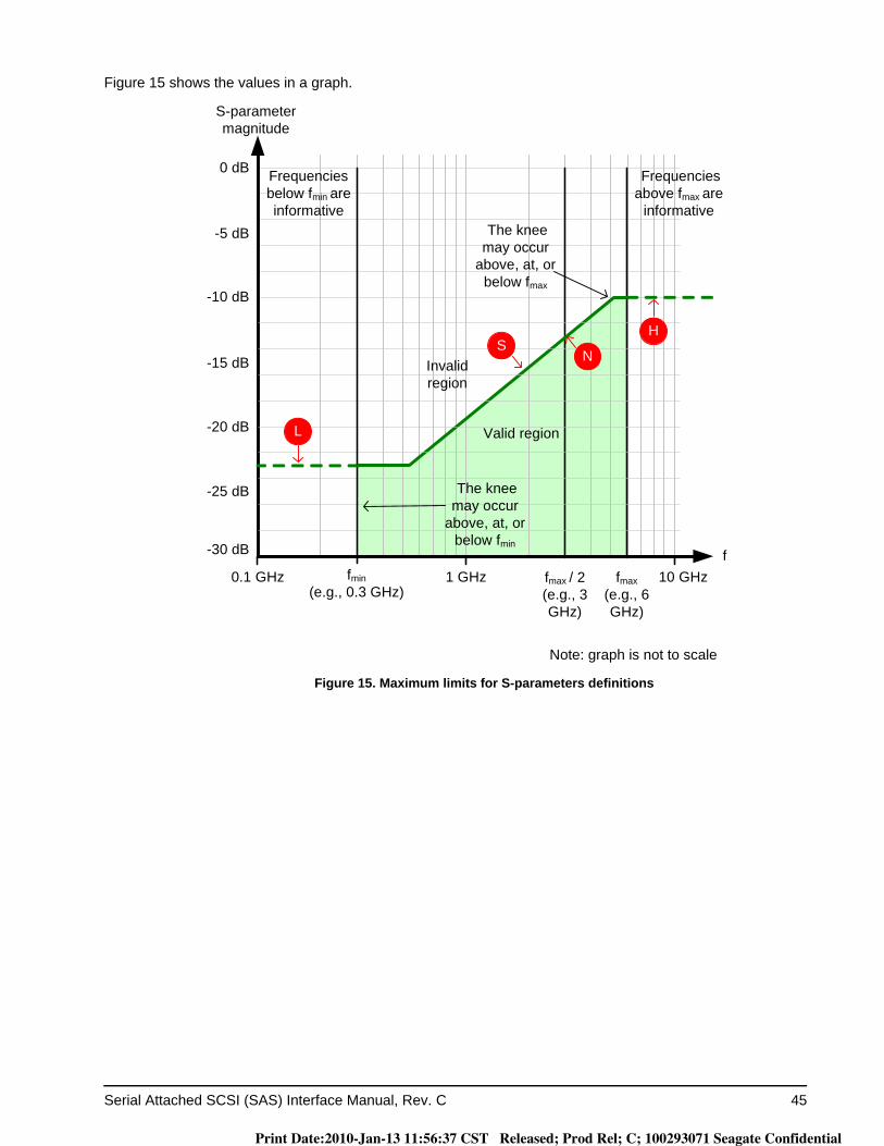
Serial Attached SCSI (SAS) Interface Manual, Rev. C 45
Figure 15 shows the values in a graph.
Figure 15. Maximum limits for S-parameters definitions
fmax(e.g., 6 GHz)
fmax / 2 (e.g., 3 GHz)
0.1 GHz 1 GHz 10 GHz
0 dB
S-parameter magnitude
f
Note: graph is not to scale
-10 dB
-25 dB
-15 dB
-20 dB
-30 dB
-5 dB
S
L
H
N
fmin(e.g., 0.3 GHz)
Frequencies below fmin are informative
Frequencies above fmax are
informative
The knee may occur
above, at, or below fmin
The knee may occur
above, at, or below fmax
Valid region
Invalid region
Print Date:2010-Jan-13 11:56:37 CST Released; Prod Rel; C; 100293071 Seagate Confidential
46 Serial Attached SCSI (SAS) Interface Manual, Rev. C
3.3 Compliance points
A TxRx connection is the complete simplex signal path between the transmitter circuit and receiver circuit (see 1.3.3).
A TxRx connection segment is that portion of a TxRx connection delimited by separable connectors or changes in conductive material.
This manual defines the electrical requirements of the signal at the compliance points IT, IR, CT, and CR in a TxRx connection. Each compliant phy shall be compatible with these electrical requirements to allow interoper-ability within a SAS environment.
Signal behavior at separable connectors requires compliance with signal characteristics defined by this manual only if the connectors are identified as compliance points by the supplier of the parts that contain the candidate compliance point.
Signal characteristics for compliance points are measured at physical positions called probe points in a test load (see 3.5). Measurements at the probe points in a test load approximate measurements at the compliance point in the actual TxRx connection. Some components in the test load may be de-embedded as described in .
Table 7 defines the compliance points.
The TxRx connection includes the characteristics of the mated connectors at both the transmitter device and receiver device ends. One end of a TxRx connection is a ITS or CTS compliance point, and the other end of the TxRx connection is the corresponding IR or CR compliance point.
Table 7. Compliance points
Compliance point Type Description
IT intra-enclosure(i.e., internal)
The signal from a transmitter device (see 1.3.3), as measured at probe points in a test load attached with an internal connector.
ITS a intra-enclosure(i.e., internal)
The location of a transmitter device where S-parameters are measured and where the TxRx connection begins. This location is at the transmitter device side of the internal connector with a test load or a TxRx connection attached with an internal connector.
IR intra-enclosure(i.e., internal)
The signal going to a receiver device (see 1.3.3), as measured at probe points in a test load attached with an internal connector.
CT inter-enclosure(i.e., cabinet)
The signal from a transmitter device, as measured at probe points in a test load attached with an external connector.
CTS a inter-enclosure(i.e., cabinet)
The location of a transmitter device where S-parameters are measured and where the TxRx connection begins. This location is at the transmitter device side of the external connector with a test load or a TxRx connection attached with an external connector.
CR inter-enclosure(i.e., cabinet)
The signal going to a receiver device, as measured at probe points in a test load attached with an external connector.
a Because the trained 1.5 Gbps, 3 Gbps, and 6 Gbps transmitter device S-parameter specifications do not include the mated connector, transmitter device S-parameter measurement points are at the ITS and CTS compliance points. 1.5 Gbps, 3 Gbps, and 6 Gbps receiver device S-parameter measurement points are at the IR and CR compliance points.
Print Date:2010-Jan-13 11:56:37 CST Released; Prod Rel; C; 100293071 Seagate Confidential
Serial Attached SCSI (SAS) Interface Manual, Rev. C 47
3.4 TxRx connection characteristics
3.4.1 TxRx connection characteristics overview
Each TxRx connection shall support a bit error ratio (BER) that is less than 10-12 (i.e., fewer than one bit error per 1012 bits). The parameters specified in this manual support meeting this requirement under all conditions including the minimum input and output amplitude levels.
A TxRx connection may be constructed from multiple TxRx connection segments (e.g., backplanes and cable assemblies). It is the responsibility of the implementer to ensure that the TxRx connection is constructed from individual TxRx connection segments such that the overall TxRx connection requirements are met. Loss char-acteristics for individual TxRx connection segments are beyond the scope of this manual.
Each TxRx connection segment shall comply with the impedance requirements detailed in 3.4.2 for the con-ductive material from which they are formed. A passive equalizer network, if present, shall be considered part of the TxRx connection.
TxRx connections shall be applied only to homogeneous ground applications (e.g., between devices within an enclosure or rack, or between enclosures interconnected by a common ground return or ground plane).
Print Date:2010-Jan-13 11:56:37 CST Released; Prod Rel; C; 100293071 Seagate Confidential

48 Serial Attached SCSI (SAS) Interface Manual, Rev. C
3.4.2 TxRx connection general characteristics
Table 8 defines the TxRx connection general characteristics.
Table 8. TxRx connection general characteristics
Characteristic a, b Units Value
Differential impedance (nominal) ohm 100
Maximum propagation delay c ns 53
Bulk cable or backplane: d, e
Differential characteristic impedance ohm 100
Mated connectors:
Differential characteristic impedance f ohm 100
Cable assembly and backplane:
Minimum |SDD21| for internal cable assemblies g, h dB -6
Minimum |SDD21| for external cable assemblies and backplanes See SAS-2
a All measurements are made through mated connector pairs.b The equivalent maximum TDR rise time from 20 % to 80 % shall be 70 ps. Filtering may be used to obtain
the equivalent rise time. The filter consists of the two-way launch/return path of the test fixture, the two-way launch/return path of the test cable, and the software or hardware filtering of the TDR scope. The equivalent rise time is the rise time of the TDR scope output after application of all filter components. When configuring software or hardware filters of the TDR scope to obtain the equivalent rise time, filtering effects of test cables and test fixtures shall be included.
c This ensures that STP flow control buffers (see SAS-2) do not overflow.d The impedance measurement identifies the impedance mismatches present in the bulk cable or
backplane when terminated in its characteristic impedance. This measurement excludes mated connectors at both ends of the bulk cable or backplane, when present, but includes any intermediate connectors or splices.
e Where the bulk cable or backplane has an electrical length of > 4 ns the procedure detailed in SFF-8410, or an equivalent procedure, shall be used to determine the impedance.
f The characteristic impedance is a measurement reference impedance for the test environment.g An internal cable assembly may be a TxRx connection segment or a full TxRx connection. The full TxRx
connection is required to comply with the requirements for intra-enclosure compliance points defined in 3.6.
h The range for this frequency domain measurement is 10 MHz to 4 500 MHz.
Print Date:2010-Jan-13 11:56:37 CST Released; Prod Rel; C; 100293071 Seagate Confidential
Serial Attached SCSI (SAS) Interface Manual, Rev. C 49
3.4.3 TxRx connection S-parameter limits
S-parameters limits are calculated per the following formula:Measured value < max [ L, min [ H, N + 13.3 × log10(f / 3 GHz) ] ]
where:L is the minimum value (i.e., the low frequency asymptote)
H is the maximum value (i.e., the high frequency asymptote)
N is the value at the Nyquist frequency (i.e., 3 GHz)
f is the frequency of the signal in Hz
max [A, B] is the maximum of A and B
min [A, B] is the minimum of A and B
Print Date:2010-Jan-13 11:56:37 CST Released; Prod Rel; C; 100293071 Seagate Confidential
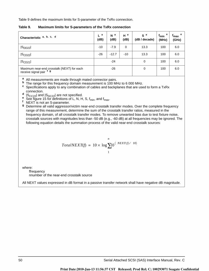
50 Serial Attached SCSI (SAS) Interface Manual, Rev. C
Table 9 defines the maximum limits for S-parameter of the TxRx connection.
Table 9. Maximum limits for S-parameters of the TxRx connection
Characteristic a, b, c, d L e(dB)
N e(dB)
H e(dB)
S e(dB / decade)
fmin e
(MHz)fmax e
(GHz)
|SDD22| -10 -7.9 0 13.3 100 6.0
|SCD22| -26 -12.7 -10 13.3 100 6.0
|SCD21| -24 0 100 6.0
Maximum near-end crosstalk (NEXT) for each receive signal pair f g
-26 0 100 6.0
a All measurements are made through mated connector pairs.b The range for this frequency domain measurement is 100 MHz to 6 000 MHz.c Specifications apply to any combination of cables and backplanes that are used to form a TxRx
connection.d |SCC22| and |SDC22| are not specified.e See figure 15 for definitions of L, N, H, S, fmin, and fmax.f NEXT is not an S-parameter.g Determine all valid aggressor/victim near-end crosstalk transfer modes. Over the complete frequency
range of this measurement, determine the sum of the crosstalk transfer ratios, measured in the frequency domain, of all crosstalk transfer modes. To remove unwanted bias due to test fixture noise, crosstalk sources with magnitudes less than -50 dB (e.g., -60 dB) at all frequencies may be ignored. The following equation details the summation process of the valid near-end crosstalk sources:
where: ffrequency nnumber of the near-end crosstalk source
All NEXT values expressed in dB format in a passive transfer network shall have negative dB magnitude.
TotalNEXT f( ) 10 10 NEXT f( ) 10⁄⟨ ⟩
1
n
∑log×=
Print Date:2010-Jan-13 11:56:37 CST Released; Prod Rel; C; 100293071 Seagate Confidential
Serial Attached SCSI (SAS) Interface Manual, Rev. C 51
Figure 16 shows the TxRx connection |SDD22|, |SCD22|, |SCD21|, and NEXT limits defined in table 9.
Figure 16. TxRx connection |SDD22|, |SCD22|, |SCD21|, and NEXT limits
3.4.4 TxRx connection characteristics for untrained 1.5 Gbps and 3 Gbps
For untrained 1.5 Gbps and 3 Gbps, each external TxRx connection shall be designed such that its loss char-acteristics are less than the loss of the TCTF test load plus ISI at CT at 3 Gbps (see figure 22 in 3.5.3) over the frequency range of 50 MHz to 3 000 MHz.
For untrained 1.5 Gbps and 3 Gbps, each internal TxRx connection shall be designed such that its loss charac-teristics are less than:
a) the loss of the TCTF test load plus ISI at IT at 3 Gbps (see figure 21 in 3.5.3) over the frequency range of 50 MHz to 3 000 MHz; or
b) if the system supports SATA devices using Gen2i levels (see SATA) but the receiver device does not support SATA Gen2i levels through the TCTF test load, the loss of the low-loss TCTF test load plus ISI (see figure 26 in 3.5.4) over the frequency range of 50 MHz to 3 000 MHz.
Each TxRx connection shall meet the delivered signal specifications in table 23 (see 3.6.5.4).
For external cable assemblies, these electrical requirements are consistent with using good quality passive cable assemblies constructed with shielded twinaxial cable with 24 AWG solid wire up to 6 m long, provided that no other TxRx connection segments are included in the TxRx connection.
0.1 GHz 1 GHz 6 GHz 10 GHz
0 dB
S-parameter magnitude
f3 GHz
Note: graph is not to scale
-10 dB
-25 dB
-15 dB
-20 dB
-30 dB
-5 dB
|SCD21|
Maximum NEXT
|SDD22|
|SCD22|
Print Date:2010-Jan-13 11:56:37 CST Released; Prod Rel; C; 100293071 Seagate Confidential
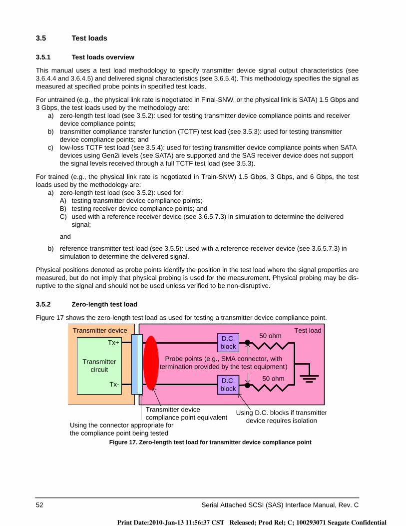
52 Serial Attached SCSI (SAS) Interface Manual, Rev. C
3.5 Test loads
3.5.1 Test loads overview
This manual uses a test load methodology to specify transmitter device signal output characteristics (see 3.6.4.4 and 3.6.4.5) and delivered signal characteristics (see 3.6.5.4). This methodology specifies the signal as measured at specified probe points in specified test loads.
For untrained (e.g., the physical link rate is negotiated in Final-SNW, or the physical link is SATA) 1.5 Gbps and 3 Gbps, the test loads used by the methodology are:
a) zero-length test load (see 3.5.2): used for testing transmitter device compliance points and receiver device compliance points;
b) transmitter compliance transfer function (TCTF) test load (see 3.5.3): used for testing transmitter device compliance points; and
c) low-loss TCTF test load (see 3.5.4): used for testing transmitter device compliance points when SATA devices using Gen2i levels (see SATA) are supported and the SAS receiver device does not support the signal levels received through a full TCTF test load (see 3.5.3).
For trained (e.g., the physical link rate is negotiated in Train-SNW) 1.5 Gbps, 3 Gbps, and 6 Gbps, the test loads used by the methodology are:
a) zero-length test load (see 3.5.2): used for:A) testing transmitter device compliance points;B) testing receiver device compliance points; andC) used with a reference receiver device (see 3.6.5.7.3) in simulation to determine the delivered
signal;
and
b) reference transmitter test load (see 3.5.5): used with a reference receiver device (see 3.6.5.7.3) in simulation to determine the delivered signal.
Physical positions denoted as probe points identify the position in the test load where the signal properties are measured, but do not imply that physical probing is used for the measurement. Physical probing may be dis-ruptive to the signal and should not be used unless verified to be non-disruptive.
3.5.2 Zero-length test load
Figure 17 shows the zero-length test load as used for testing a transmitter device compliance point.
Figure 17. Zero-length test load for transmitter device compliance point
Test load50 ohm
50 ohm
Probe points (e.g., SMA connector, with termination provided by the test equipment)
Using the connector appropriate for the compliance point being tested
Using D.C. blocks if transmitterdevice requires isolation
D.C. block
D.C. block
Transmitter device
Transmitter circuit
Tx+
Tx-
Transmitter device compliance point equivalent
Print Date:2010-Jan-13 11:56:37 CST Released; Prod Rel; C; 100293071 Seagate Confidential

Serial Attached SCSI (SAS) Interface Manual, Rev. C 53
Figure 18 shows the zero-length test load as used for testing a receiver device compliance point.
Figure 18. Zero-length test load for receiver device compliance point
Figure 17 and figure 18 show ideal designs. Implementations may include:a) insertion loss between the compliance and probe points; andb) return loss due one or more impedance mismatches between the compliance point and 50 ohm termi-
nation points.
Not shown are non-ideal effects of the test equipment raw measurements (e.g., additional insertion loss and return loss). For de-embedding methods to remove non-ideal effects see SAS-2.
Usage of fixturing and test equipment shall comply with the requirements defined in this subclause. The requirements in this subclause include the combined effects of the fixturing and test equipment.
The zero-length test load is defined by a set of S-parameters (see SAS-2). Only the magnitude of SDD21(f) and the magnitude of SDD11(f) are specified by this manual.
The zero-length test load, including all fixturing and instrumentation required for the measurement, shall com-ply with the following equations:
For 50 MHz < f ≤ 6.0 GHz:
|SDD21(f)| -20 × log10(e) × ((1.0 × 10⁻⁶ × f0.5) + (2.8 × 10⁻¹¹ × f) + (5.3 × 10⁻²¹ × f2)) - 0.2 dB|SDD11(f)| ≤ -15 dB
where:|SDD21(f)| magnitude of SDD21(f)
|SDD11(f)| magnitude of SDD11(f)
f signal frequency in Hz
Transmitter device
Transmitter circuit
Tx+
Tx-
TxRx connection, if any
Test load50 ohm
50 ohm
Probe points (e.g., SMA connector, with termination provided by the test equipment)
Using D.C. blocks if transmitterdevice requires isolation
D.C. block
D.C. block
Receiver device compliance point equivalent
Using the connector appropriate for the compliance point being tested
Print Date:2010-Jan-13 11:56:37 CST Released; Prod Rel; C; 100293071 Seagate Confidential
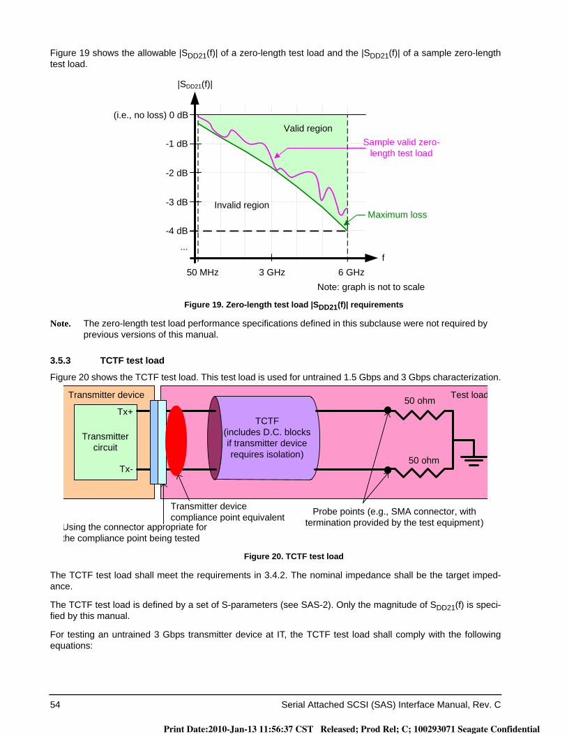
54 Serial Attached SCSI (SAS) Interface Manual, Rev. C
Figure 19 shows the allowable |SDD21(f)| of a zero-length test load and the |SDD21(f)| of a sample zero-length test load.
Figure 19. Zero-length test load |SDD21(f)| requirements
Note. The zero-length test load performance specifications defined in this subclause were not required by previous versions of this manual.
3.5.3 TCTF test load
Figure 20 shows the TCTF test load. This test load is used for untrained 1.5 Gbps and 3 Gbps characterization.
Figure 20. TCTF test load
The TCTF test load shall meet the requirements in 3.4.2. The nominal impedance shall be the target imped-ance.
The TCTF test load is defined by a set of S-parameters (see SAS-2). Only the magnitude of SDD21(f) is speci-fied by this manual.
For testing an untrained 3 Gbps transmitter device at IT, the TCTF test load shall comply with the following equations:
-4 dB
f
(i.e., no loss) 0 dB
|SDD21(f)|
Maximum loss
Sample valid zero-length test load
6 GHz50 MHz
Valid region
Invalid region
3 GHz
-3 dB
-2 dB
-1 dB
...
Note: graph is not to scale
Transmitter device Test load
Transmitter circuit
Tx+
Tx-
TCTF(includes D.C. blocksif transmitter device requires isolation)
Using the connector appropriate for the compliance point being tested
50 ohm
50 ohm
Probe points (e.g., SMA connector, with termination provided by the test equipment)
Transmitter device compliance point equivalent
Print Date:2010-Jan-13 11:56:37 CST Released; Prod Rel; C; 100293071 Seagate Confidential
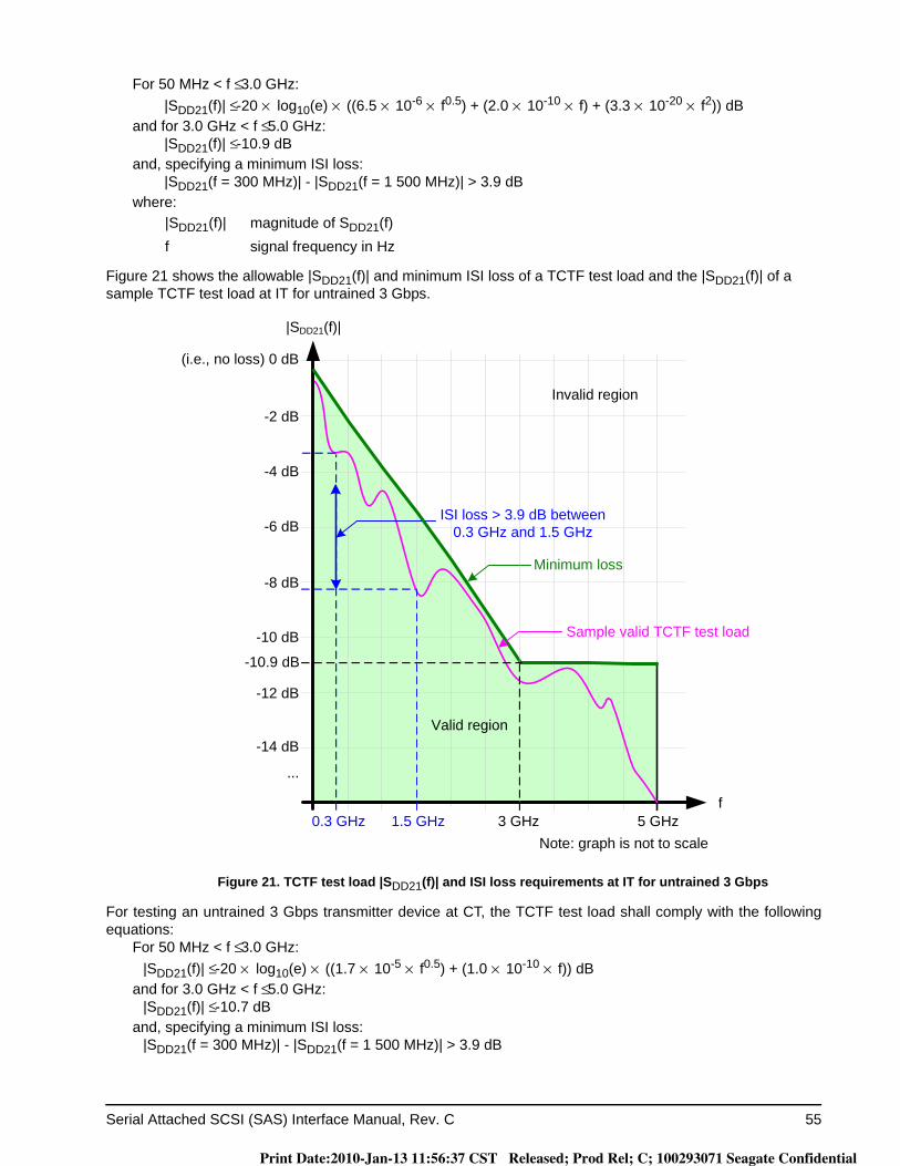
Serial Attached SCSI (SAS) Interface Manual, Rev. C 55
For 50 MHz < f ≤ 3.0 GHz:|SDD21(f)| ≤ -20 × log10(e) × ((6.5 × 10⁻⁶ × f0.5) + (2.0 × 10⁻¹⁰ × f) + (3.3 × 10⁻²⁰ × f2)) dB
and for 3.0 GHz < f ≤ 5.0 GHz:|SDD21(f)| ≤ -10.9 dB
and, specifying a minimum ISI loss:|SDD21(f = 300 MHz)| - |SDD21(f = 1 500 MHz)| > 3.9 dB
where:
Figure 21 shows the allowable |SDD21(f)| and minimum ISI loss of a TCTF test load and the |SDD21(f)| of a sample TCTF test load at IT for untrained 3 Gbps.
Figure 21. TCTF test load |SDD21(f)| and ISI loss requirements at IT for untrained 3 Gbps
For testing an untrained 3 Gbps transmitter device at CT, the TCTF test load shall comply with the following equations:
For 50 MHz < f ≤ 3.0 GHz:|SDD21(f)| ≤ -20 × log10(e) × ((1.7 × 10⁻⁵ × f0.5) + (1.0 × 10⁻¹⁰ × f)) dB
and for 3.0 GHz < f ≤ 5.0 GHz:|SDD21(f)| ≤ -10.7 dB
and, specifying a minimum ISI loss:|SDD21(f = 300 MHz)| - |SDD21(f = 1 500 MHz)| > 3.9 dB
|SDD21(f)| magnitude of SDD21(f)f signal frequency in Hz
-10.9 dB
f
(i.e., no loss) 0 dB
|SDD21(f)|
Minimum loss
Sample valid TCTF test load
3 GHz1.5 GHz 5 GHz
-8 dB
-6 dB
-4 dB
-2 dB
-10 dB
-12 dB
-14 dB
ISI loss > 3.9 dB between 0.3 GHz and 1.5 GHz
0.3 GHz
Invalid region
Valid region
...
Note: graph is not to scale
Print Date:2010-Jan-13 11:56:37 CST Released; Prod Rel; C; 100293071 Seagate Confidential
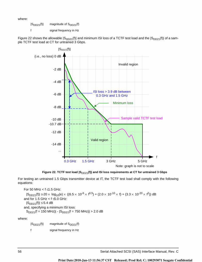
56 Serial Attached SCSI (SAS) Interface Manual, Rev. C
where:
Figure 22 shows the allowable |SDD21(f)| and minimum ISI loss of a TCTF test load and the |SDD21(f)| of a sam-ple TCTF test load at CT for untrained 3 Gbps.
Figure 22. TCTF test load |SDD21(f)| and ISI loss requirements at CT for untrained 3 Gbps
For testing an untrained 1.5 Gbps transmitter device at IT, the TCTF test load shall comply with the following equations:
For 50 MHz < f ≤ 1.5 GHz:|SDD21(f)| ≤ -20 × log10(e) × ((6.5 × 10⁻⁶ × f0.5) + (2.0 × 10⁻¹⁰ × f) + (3.3 × 10⁻²⁰ × f2)) dB
and for 1.5 GHz < f ≤ 5.0 GHz:|SDD21(f)| ≤ -5.4 dB
and, specifying a minimum ISI loss:SDD21(f = 150 MHz)| - |SDD21(f = 750 MHz)| > 2.0 dB
where:
|SDD21(f)| magnitude of SDD21(f)
f signal frequency in Hz
|SDD21(f)| magnitude of SDD21(f)
f signal frequency in Hz
-10.7 dB
f
(i.e., no loss) 0 dB
|SDD21(f)|
Minimum loss
Sample valid TCTF test load
3 GHz1.5 GHz 5 GHzNote: graph is not to scale
-8 dB
-6 dB
-4 dB
-2 dB
-10 dB
-12 dB
-14 dB
ISI loss > 3.9 dB between 0.3 GHz and 1.5 GHz
0.3 GHz
...
Invalid region
Valid region
Print Date:2010-Jan-13 11:56:37 CST Released; Prod Rel; C; 100293071 Seagate Confidential
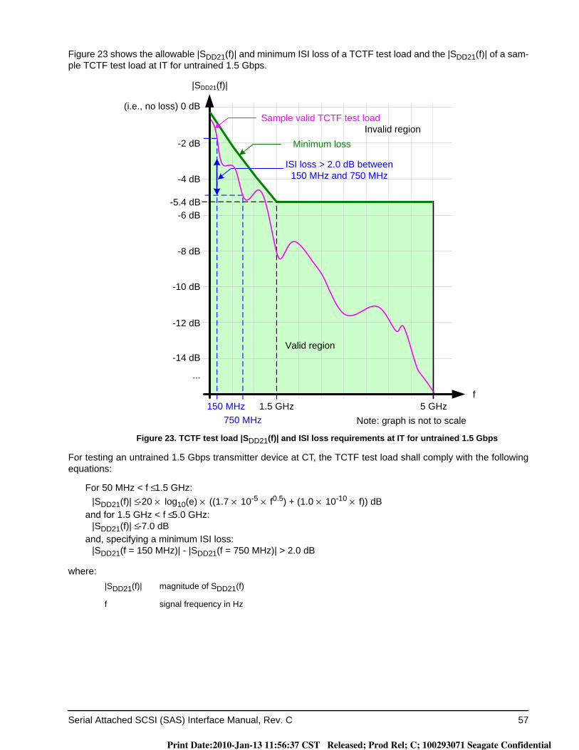
Serial Attached SCSI (SAS) Interface Manual, Rev. C 57
Figure 23 shows the allowable |SDD21(f)| and minimum ISI loss of a TCTF test load and the |SDD21(f)| of a sam-ple TCTF test load at IT for untrained 1.5 Gbps.
Figure 23. TCTF test load |SDD21(f)| and ISI loss requirements at IT for untrained 1.5 Gbps
For testing an untrained 1.5 Gbps transmitter device at CT, the TCTF test load shall comply with the following equations:
For 50 MHz < f ≤ 1.5 GHz:|SDD21(f)| ≤ -20 × log10(e) × ((1.7 × 10⁻⁵ × f0.5) + (1.0 × 10⁻¹⁰ × f)) dB
and for 1.5 GHz < f ≤ 5.0 GHz:|SDD21(f)| ≤ -7.0 dB
and, specifying a minimum ISI loss:|SDD21(f = 150 MHz)| - |SDD21(f = 750 MHz)| > 2.0 dB
where:|SDD21(f)| magnitude of SDD21(f)
f signal frequency in Hz
f
(i.e., no loss) 0 dB
|SDD21(f)|
1.5 GHz750 MHz
5 GHzNote: graph is not to scale
-8 dB
-4 dB
-2 dB
-10 dB
-12 dB
-14 dB
150 MHz
...
Invalid region
Valid region
-6 dB-5.4 dB
Sample valid TCTF test load
ISI loss > 2.0 dB between 150 MHz and 750 MHz
Minimum loss
Print Date:2010-Jan-13 11:56:37 CST Released; Prod Rel; C; 100293071 Seagate Confidential
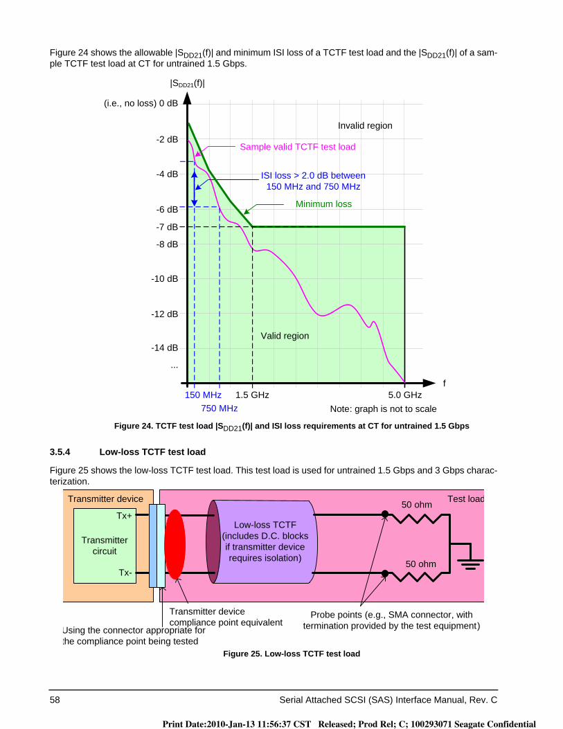
58 Serial Attached SCSI (SAS) Interface Manual, Rev. C
Figure 24 shows the allowable |SDD21(f)| and minimum ISI loss of a TCTF test load and the |SDD21(f)| of a sam-ple TCTF test load at CT for untrained 1.5 Gbps.
Figure 24. TCTF test load |SDD21(f)| and ISI loss requirements at CT for untrained 1.5 Gbps
3.5.4 Low-loss TCTF test load
Figure 25 shows the low-loss TCTF test load. This test load is used for untrained 1.5 Gbps and 3 Gbps charac-terization.
Figure 25. Low-loss TCTF test load
f
(i.e., no loss) 0 dB
|SDD21(f)|
Minimum loss
Sample valid TCTF test load
1.5 GHz750 MHz
5.0 GHzNote: graph is not to scale
-8 dB
-4 dB
-2 dB
-10 dB
-12 dB
-14 dB
ISI loss > 2.0 dB between 150 MHz and 750 MHz
150 MHz
...
Invalid region
Valid region
-7 dB
-6 dB
Transmitter device Test load
Transmitter circuit
Tx+
Tx-
Low-loss TCTF(includes D.C. blocksif transmitter device requires isolation)
Using the connector appropriate for the compliance point being tested
50 ohm
50 ohm
Probe points (e.g., SMA connector, with termination provided by the test equipment)
Transmitter device compliance point equivalent
Print Date:2010-Jan-13 11:56:37 CST Released; Prod Rel; C; 100293071 Seagate Confidential
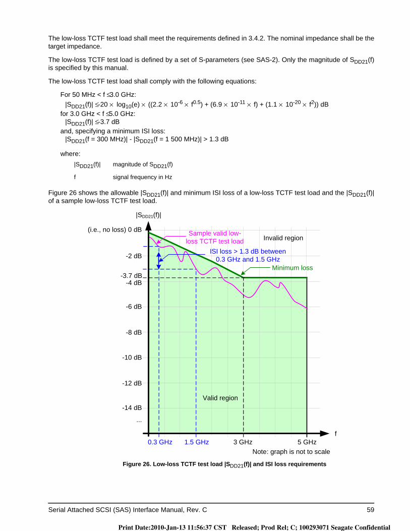
Serial Attached SCSI (SAS) Interface Manual, Rev. C 59
The low-loss TCTF test load shall meet the requirements defined in 3.4.2. The nominal impedance shall be the target impedance.
The low-loss TCTF test load is defined by a set of S-parameters (see SAS-2). Only the magnitude of SDD21(f) is specified by this manual.
The low-loss TCTF test load shall comply with the following equations:
For 50 MHz < f ≤ 3.0 GHz:|SDD21(f)| ≤ -20 × log10(e) × ((2.2 × 10⁻⁶ × f0.5) + (6.9 × 10⁻¹¹ × f) + (1.1 × 10⁻²⁰ × f2)) dB
for 3.0 GHz < f ≤ 5.0 GHz:|SDD21(f)| ≤ -3.7 dB
and, specifying a minimum ISI loss:|SDD21(f = 300 MHz)| - |SDD21(f = 1 500 MHz)| > 1.3 dB
where:
Figure 26 shows the allowable |SDD21(f)| and minimum ISI loss of a low-loss TCTF test load and the |SDD21(f)| of a sample low-loss TCTF test load.
Figure 26. Low-loss TCTF test load |SDD21(f)| and ISI loss requirements
|SDD21(f)| magnitude of SDD21(f)
f signal frequency in Hz
f
(i.e., no loss) 0 dB
|SDD21(f)|
Sample valid low-loss TCTF test load
3 GHz1.5 GHz 5 GHzNote: graph is not to scale
-8 dB
-6 dB
-4 dB
-2 dB
-10 dB
-12 dB
-14 dB
0.3 GHz
Invalid region
Valid region
...
-3.7 dB
ISI loss > 1.3 dB between 0.3 GHz and 1.5 GHz
Minimum loss
Print Date:2010-Jan-13 11:56:37 CST Released; Prod Rel; C; 100293071 Seagate Confidential
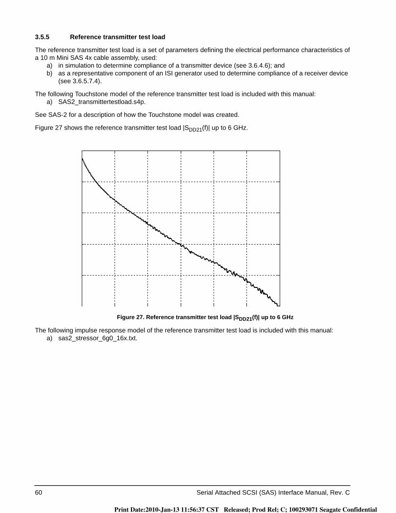
60 Serial Attached SCSI (SAS) Interface Manual, Rev. C
3.5.5 Reference transmitter test load
The reference transmitter test load is a set of parameters defining the electrical performance characteristics of a 10 m Mini SAS 4x cable assembly, used:
a) in simulation to determine compliance of a transmitter device (see 3.6.4.6); andb) as a representative component of an ISI generator used to determine compliance of a receiver device
(see 3.6.5.7.4).
The following Touchstone model of the reference transmitter test load is included with this manual:a) SAS2_transmittertestload.s4p.
See SAS-2 for a description of how the Touchstone model was created.
Figure 27 shows the reference transmitter test load |SDD21(f)| up to 6 GHz.
Figure 27. Reference transmitter test load |SDD21(f)| up to 6 GHz
The following impulse response model of the reference transmitter test load is included with this manual:a) sas2_stressor_6g0_16x.txt.
Print Date:2010-Jan-13 11:56:37 CST Released; Prod Rel; C; 100293071 Seagate Confidential
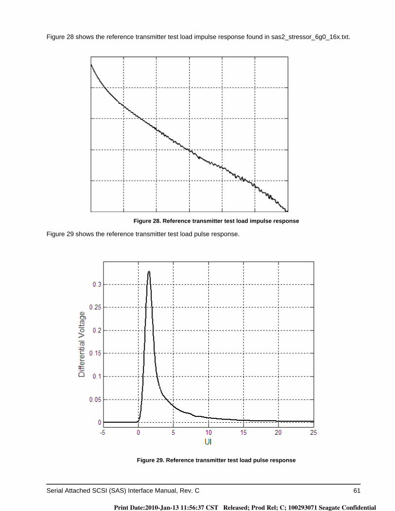
Serial Attached SCSI (SAS) Interface Manual, Rev. C 61
Figure 28 shows the reference transmitter test load impulse response found in sas2_stressor_6g0_16x.txt.
Figure 28. Reference transmitter test load impulse response
Figure 29 shows the reference transmitter test load pulse response.
Figure 29. Reference transmitter test load pulse response
Print Date:2010-Jan-13 11:56:37 CST Released; Prod Rel; C; 100293071 Seagate Confidential
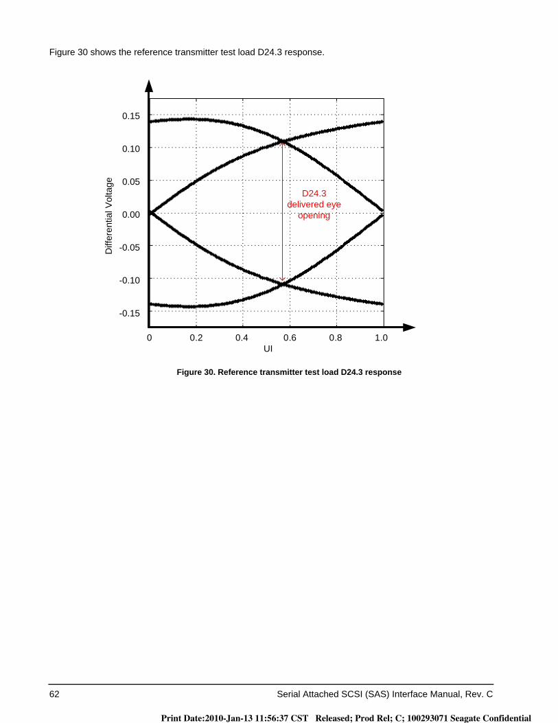
62 Serial Attached SCSI (SAS) Interface Manual, Rev. C
Figure 30 shows the reference transmitter test load D24.3 response.
Figure 30. Reference transmitter test load D24.3 response
0.15
0.10
0.05
0.00
-0.05
-0.10
-0.15
0 0.2 0.4 0.6 0.8 1.0 UI
Diff
eren
tial V
olta
ge
D24.3 delivered eye
opening
Print Date:2010-Jan-13 11:56:37 CST Released; Prod Rel; C; 100293071 Seagate Confidential

Serial Attached SCSI (SAS) Interface Manual, Rev. C 63
3.6 Transmitter device and receiver device electrical characteristics
3.6.1 General electrical characteristics
Table 10 defines the general electrical characteristics, which apply to both transmitter devices and receiver devices.
3.6.2 Transmitter device and receiver device transients
Transients may occur at transmitter devices or receiver devices as a result of changes in supply power condi-tions or mode transitions.
A mode transition is an event that may result in a measurable transient due to the response of the transmitter device or receiver device. The following conditions constitute a mode transition:
a) enabling or disabling driver circuitry;b) enabling or disabling receiver common-mode circuitry;c) hot plug event;d) adjusting driver amplitude;e) enabling or disabling de-emphasis; andf) adjusting terminator impedance.
Transmitter device transients are measured at nodes VP and VN with respect to GROUND on the test circuit shown in figure 31 during all power state and mode transitions. Receiver device transients are measured at nodes VP and VN with respect to GROUND on the test circuit shown in figure 32 during all power state and mode transitions. Test conditions shall include power supply power on and power off conditions, voltage sequencing, and mode transitions.
Table 10. General electrical characteristics
Characteristic Units 1.5 Gbps(i.e., G1)
3 Gbps (i.e., G2)
6 Gbps (i.e., G3)
Physical link rate (nominal) MBps 150 300 600
Unit interval (UI)(nominal) a ps 666.6 333.3 166.6
Baud rate (fbaud)(nominal) Gigasymbols/s 1.5 3 6
Maximum A.C. coupling capacitor b nF 12
Maximum noise during OOB idle time c mV(P-P) 120
a 666.6 equals 2000 / 3. 333.3 equals 1000 / 3. 166.6 equals 500 / 3.b The coupling capacitor value for A.C. coupled transmit and receive pairs. See 3.6.4.2 for A.C. coupling
requirements for transmitter devices. See 3.6.5.2 for A.C. coupling requirements for receiver devices. The equivalent series resistance at 3 GHz should be less than 1 ohm.
c With a measurement bandwidth of 1.5 × fbaud (e.g., 9 GHz for 6 Gbps), no signal level during the idle time shall exceed the specified maximum differential amplitude.
Print Date:2010-Jan-13 11:56:37 CST Released; Prod Rel; C; 100293071 Seagate Confidential
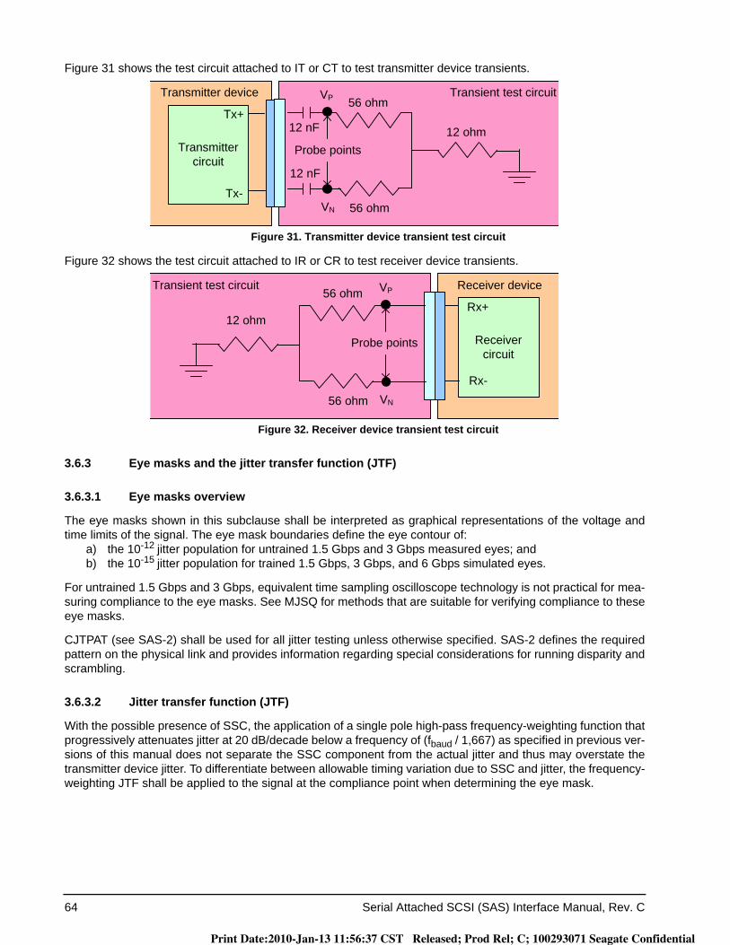
64 Serial Attached SCSI (SAS) Interface Manual, Rev. C
Figure 31 shows the test circuit attached to IT or CT to test transmitter device transients.
Figure 31. Transmitter device transient test circuit
Figure 32 shows the test circuit attached to IR or CR to test receiver device transients.
Figure 32. Receiver device transient test circuit
3.6.3 Eye masks and the jitter transfer function (JTF)
3.6.3.1 Eye masks overview
The eye masks shown in this subclause shall be interpreted as graphical representations of the voltage and time limits of the signal. The eye mask boundaries define the eye contour of:
a) the 10-12 jitter population for untrained 1.5 Gbps and 3 Gbps measured eyes; andb) the 10-15 jitter population for trained 1.5 Gbps, 3 Gbps, and 6 Gbps simulated eyes.
For untrained 1.5 Gbps and 3 Gbps, equivalent time sampling oscilloscope technology is not practical for mea-suring compliance to the eye masks. See MJSQ for methods that are suitable for verifying compliance to these eye masks.
CJTPAT (see SAS-2) shall be used for all jitter testing unless otherwise specified. SAS-2 defines the required pattern on the physical link and provides information regarding special considerations for running disparity and scrambling.
3.6.3.2 Jitter transfer function (JTF)
With the possible presence of SSC, the application of a single pole high-pass frequency-weighting function that progressively attenuates jitter at 20 dB/decade below a frequency of (fbaud / 1,667) as specified in previous ver-sions of this manual does not separate the SSC component from the actual jitter and thus may overstate the transmitter device jitter. To differentiate between allowable timing variation due to SSC and jitter, the frequency-weighting JTF shall be applied to the signal at the compliance point when determining the eye mask.
Transient test circuit
12 nF
56 ohm
Probe points
12 nF
12 ohm
VP
VN
56 ohmTransmitter device
Transmitter circuit
Tx+
Tx-
Transient test circuit
Probe points
12 ohm
VP
VN
56 ohmReceiver device
Receiver circuit
Rx+
Rx-
56 ohm
Print Date:2010-Jan-13 11:56:37 CST Released; Prod Rel; C; 100293071 Seagate Confidential

Serial Attached SCSI (SAS) Interface Manual, Rev. C 65
The jitter measurement device shall comply with the JTF. The reference clock characteristics are controlled by the resulting JTF characteristics obtained by taking the time difference between the PLL output (i.e., the refer-ence clock) and the data stream sourced to the PLL. The PLL’s closed loop transfer function’s -3 dB corner fre-quency and other adjustable parameters (e.g., peaking) are determined by the value required to meet the requirements of the JTF.
The JTF shall have the following characteristics for a repeating 0011b or 1100b pattern (e.g., D24.3)(see SAS-2):
a) the -3 dB corner frequency of the JTF shall be 2.6 ± 0.5 MHz;b) the magnitude peaking of the JTF shall be 3.5 dB maximum; andc) the attenuation at 30 kHz ± 1 % shall be 72 dB to 75 dB.
The JTF -3 dB corner frequency and the magnitude peaking requirements shall be measured with SJ applied, with a peak-to-peak amplitude of 0.3 UI ± 10 %. The relative attenuation at 30 kHz shall be measured with sinusoidal phase (i.e., time) modulation applied, with a peak-to-peak amplitude of 20.8 ns ± 10 %.
A proportional decrease of the JTF -3 dB corner frequency should be observed for a decrease in pattern tran-sition density compared to a 0.5 transition density. If a jitter measurement device (JMD) shifts the JTF -3 dB corner frequency in a manner that does not match this characteristic, or does not shift at all, then measure-ments of jitter with patterns with transition densities different than 0.5 may lead to discrepancies in reported jit-ter levels. In the case of reported jitter discrepancies between JMDs, the JMD with the shift of the -3 dB corner frequency that is closest to the proportional characteristic of the reference transmitter test load (see 3.5.5) shall be considered correct. This characteristic may be measured with the conditions defined above for measuring the -3 dB corner frequency, but substituting other patterns with different transition densities.
3.6.3.3 Transmitter device eye mask for untrained 1.5 Gbps and 3 Gbps
Figure 33 describes the eye mask used for testing the signal output of the transmitter device at IT and CT for untrained 1.5 Gbps and 3 Gbps (see table 14 in 3.6.4.5) and OOB signals (see table 20 in 3.6.4.7). This eye mask applies to jitter after the application of the JTF (see 3.6.3.2).
Figure 33. Transmitter device eye mask
Verifying compliance with the limits represented by the transmitter device eye mask should be done with reverse channel traffic present on the channel under test and with forward and reverse traffic present on all other channels, in order that the effects of crosstalk are taken into account.
Receiver device eye mask for untrained 1.5 Gbps and 3 Gbps
Absolute amplitude
(in V)
Z1
Z2
0 V
-Z1
-Z2
X1 X21-X2
1-X1
Normalized time (in UI)
0 1
Print Date:2010-Jan-13 11:56:37 CST Released; Prod Rel; C; 100293071 Seagate Confidential

66 Serial Attached SCSI (SAS) Interface Manual, Rev. C
Figure 34 describes the eye mask used for testing the the signal delivered to the receiver device at IR and CR for untrained 1.5 Gbps and 3 Gbps (see table 23 in 3.6.5.4). This eye mask applies to jitter after the application of the JTF (see 3.6.3.2). This requirement accounts for the low frequency tracking properties and response time of the CDR circuitry in receiver devices.
Figure 34. Receiver device eye mask
Verifying compliance with the limits represented by the receiver device eye mask should be done with reverse channel traffic present on the channel-under-test and with forward and reverse traffic present on all other chan-nels, in order that the effects of crosstalk are taken into account.
3.6.3.4 Receiver device jitter tolerance eye mask for untrained 1.5 Gbps and 3 Gbps
Figure 35 describes the eye mask used to test the jitter tolerance of the receiver device at IR and CR for untrained 1.5 Gbps and 3 Gbps (see table 23 in 3.6.5.4). For trained 1.5 Gbps, 3 Gbps, and 6 Gbps, jitter toler-ance is included in the delivered signal specifications for stressed receiver device jitter tolerance testing (see 3.6.5.7.4).
The eye mask shall be constructed as follows:a) X2 and Z2 shall be the values for the delivered signal listed in table 23 (see 3.6.5.4);b) X1OP shall be half the value of TJ for maximum delivered jitter listed in table 24 (see 3.6.5.5); and
Absolute amplitude
(in V)
Z1
Z2
0 V
-Z1
-Z2
X1 X21-X2
1-X1
Normalized time (in UI)
0 1
Print Date:2010-Jan-13 11:56:37 CST Released; Prod Rel; C; 100293071 Seagate Confidential

Serial Attached SCSI (SAS) Interface Manual, Rev. C 67
c) X1TOL shall be half the value of TJ for receiver device jitter tolerance listed in table 25 (see 3.6.5.6), for applied SJ frequencies above (fbaud / 1,667).
Figure 35. Deriving a receiver device jitter tolerance eye mask for untrained 1.5 Gbps and 3 Gbps
The leading and trailing edge slopes of the receiver device eye mask in figure 34 (see ) shall be preserved. As a result, the amplitude value of Z1 is less than that given for the delivered signal in table 23 (see 3.6.5.4), and Z1TOL and Z1OP shall be defined from those slopes by the following equation:
where:
The X1 points in the receiver device jitter tolerance eye mask (see figure 35) are greater than the X1 points in the receiver device eye mask (see figure 34) due to the addition of SJ.
3.6.4 Transmitter device characteristics
3.6.4.1 Transmitter device characteristics overview
Transmitter devices may or may not incorporate de-emphasis (i.e., pre-emphasis) and other forms of compen-sation. The transmitter device shall use the same settings (e.g., de-emphasis and voltage swing) with both the zero-length test load and the appropriate TCTF test load or reference transmitter test load (see 3.5).
SeeSAS-2 for a methodology for measuring transmitter device signal output.
Z1TOL is the value for Z1 to be used for the receiver device jitter tolerance eye maskZ1OP is the Z1 value for the delivered signal in table 23X1OP is the X1 value for the delivered signal in table 23X2 is the X2 value for the delivered signal in table 23
ASJ is the additional SJ for applied SJ frequencies above (fbaud / 1,667) (see figure 41 in 3.6.5.6)
Absolute amplitude
(in V)
Z1TOL
0 V
-Z1OP
X1OPX2
1-X1TOL
1-X1OP
Normalized time (in UI)
(additional SJ) / 2
-Z1TOL
Z1OP
X1TOL
Outline of eye mask after adding SJ
Outline of eye mask before adding SJ
0 1
Z2
-Z2
Z1TOL Z1OP
X2 ASJ2
----------⎝ ⎠⎛ ⎞– X1OP–
X2 X1OP–------------------------------------------------×=
Print Date:2010-Jan-13 11:56:37 CST Released; Prod Rel; C; 100293071 Seagate Confidential
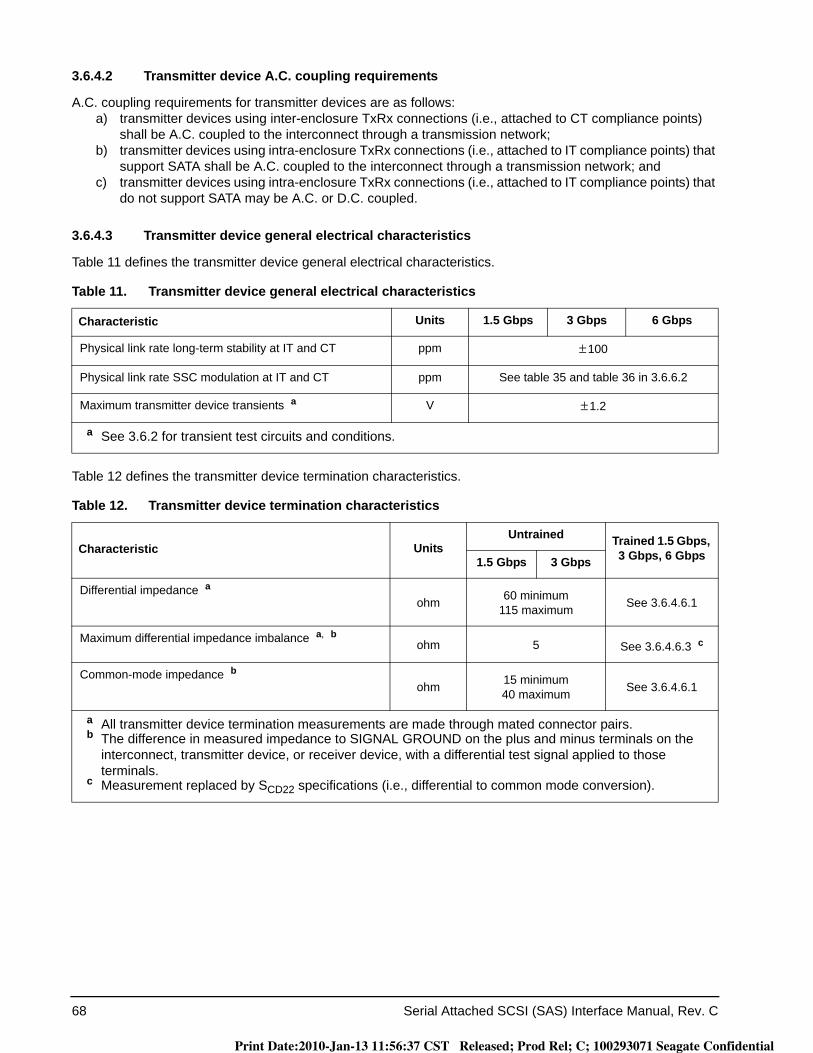
68 Serial Attached SCSI (SAS) Interface Manual, Rev. C
3.6.4.2 Transmitter device A.C. coupling requirements
A.C. coupling requirements for transmitter devices are as follows:a) transmitter devices using inter-enclosure TxRx connections (i.e., attached to CT compliance points)
shall be A.C. coupled to the interconnect through a transmission network;b) transmitter devices using intra-enclosure TxRx connections (i.e., attached to IT compliance points) that
support SATA shall be A.C. coupled to the interconnect through a transmission network; andc) transmitter devices using intra-enclosure TxRx connections (i.e., attached to IT compliance points) that
do not support SATA may be A.C. or D.C. coupled.
3.6.4.3 Transmitter device general electrical characteristics
Table 11 defines the transmitter device general electrical characteristics.
Table 12 defines the transmitter device termination characteristics.
Table 11. Transmitter device general electrical characteristics
Characteristic Units 1.5 Gbps 3 Gbps 6 Gbps
Physical link rate long-term stability at IT and CT ppm ± 100
Physical link rate SSC modulation at IT and CT ppm See table 35 and table 36 in 3.6.6.2
Maximum transmitter device transients a V ± 1.2
a See 3.6.2 for transient test circuits and conditions.
Table 12. Transmitter device termination characteristics
Characteristic UnitsUntrained Trained 1.5 Gbps,
3 Gbps, 6 Gbps1.5 Gbps 3 Gbps
Differential impedance aohm 60 minimum
115 maximum See 3.6.4.6.1
Maximum differential impedance imbalance a, b ohm 5 See 3.6.4.6.3 c
Common-mode impedance bohm 15 minimum
40 maximum See 3.6.4.6.1
a All transmitter device termination measurements are made through mated connector pairs.b The difference in measured impedance to SIGNAL GROUND on the plus and minus terminals on the
interconnect, transmitter device, or receiver device, with a differential test signal applied to those terminals.
c Measurement replaced by SCD22 specifications (i.e., differential to common mode conversion).
Print Date:2010-Jan-13 11:56:37 CST Released; Prod Rel; C; 100293071 Seagate Confidential
Serial Attached SCSI (SAS) Interface Manual, Rev. C 69
3.6.4.4 Transmitter device signal output characteristics for untrained 1.5 Gbps and 3 Gbps as mea-sured with the zero-length test load
Table 13 specifies the signal output characteristics for the transmitter device for untrained 1.5 Gbps and 3 Gbps as measured with the zero-length test load (see 3.5.2) attached at a transmitter device compliance point (i.e., IT or CT). All specifications are based on differential measurements. See 3.6.4.6 for trained 1.5 Gbps, 3 Gbps, and 6 Gbps transmitter device signal output characteristics.
3.6.4.5 Transmitter device signal output characteristics for untrained 1.5 Gbps and 3 Gbps as mea-sured with each test load
Table 14 specifies the signal output characteristics for the transmitter device for untrained 1.5 Gbps and 3 Gbps as measured with each test load (i.e., the zero-length test load (see 3.5.2) and either the TCTF test load (see 3.5.3) or the low-loss TCTF test load (see 3.5.4)) attached at a transmitter device compliance point (i.e., IT or CT). All specifications are based on differential measurements. See 3.6.4.6 for trained 1.5 Gbps, 3 Gbps, and 6 Gbps transmitter device signal output characteristics.
Table 13. Transmitter device signal output characteristics for untrained 1.5 Gbps and 3 Gbps as measured with the zero-length test load at IT and CT
Signal characteristic a UnitsUntrained
1.5 Gbps 3 Gbps
Maximum intra-pair skew b ps 20 15
Maximum transmitter device off voltage c mV(P-P) 50
Maximum (i.e., slowest) rise/fall time d ps 273 137
Minimum (i.e., fastest) rise/fall time d ps 67
Maximum transmitter output imbalance e % 10
a All tests in this table shall be performed with zero-length test load (see 3.5.2).b The intra-pair skew measurement shall be made at the midpoint of the transition with a repeating 01b or
10b pattern (e.g., D10.2 or D21.5)(see SAS-2) on the physical link. The same stable trigger, coherent to the data stream, shall be used for both the Tx+ and Tx- signals. Intra-pair skew is defined as the time difference between the means of the midpoint crossing times of the Tx+ signal and the Tx- signal.
c The transmitter device off voltage is the maximum A.C. voltage measured at compliance points IT and CT when the transmitter is unpowered or transmitting D.C. idle (e.g., during idle time of an OOB signal).
d Rise/fall times are measured from 20 % to 80 % of the transition with a repeating 01b or 10b pattern (e.g., D10.2 or D21.5)(see SAS-2) on the physical link.
e The maximum difference between the V+ and V- A.C. rms transmitter device amplitudes measured with CJTPAT (seaa SAS-2) into the zero-length test load shown in figure 17 (see 3.5.2), as a percentage of the average of the V+ and V- A.C. rms amplitudes.
Print Date:2010-Jan-13 11:56:37 CST Released; Prod Rel; C; 100293071 Seagate Confidential
70 Serial Attached SCSI (SAS) Interface Manual, Rev. C
3.6.4.6 Transmitter device signal output characteristics for trained 1.5 Gbps, 3 Gbps, and 6 Gbps
Table 14. Transmitter device signal output characteristics for untrained 1.5 Gbps and 3 Gbps as measured with each test load at IT and CT
Signal characteristic UnitsIT, untrained CT, untrained
1.5 Gbps 3 Gbps 1.5 Gbps 3 Gbps
Maximum voltage (non-operational) mV(P-P) 2,000
Maximum peak to peak voltage (i.e., 2 × Z2 in figure 33) if SATA is not supported
mV(P-P) 1,600
Maximum peak to peak voltage (i.e., 2 × Z2 in figure 33) if SATA is supported
mV(P-P) see SATA a N/A
Minimum eye opening (i.e., 2 × Z1 in figure 33), if SATA is not supported
mV(P-P) 325 275 275
Minimum eye opening (i.e., 2 × Z1 in figure 33), if SATA is supported
mV(P-P) see SATA a N/A
Maximum DJ b, c, d UI 0.35
Maximum half of TJ (i.e., X1 in figure 33) b, c, d, e, f, h, i
UI 0.275
Center of bit time (i.e., X2 in figure 33) UI 0.50
Maximum intra-pair skew j ps 80 75 80 75
a Amplitude measurement methodologies of SATA and this manual differ. Under conditions of maximum rise/fall time and jitter, eye diagram methodologies used in this manual may indicate less signal amplitude than the technique specified by SATA. Implementers of designs supporting SATA are required to ensure interoperability and should perform additional system characterization with an eye diagram methodology using SATA devices.
b All DJ and TJ values are level 1 (see MJSQ).c The values for jitter in this table are measured at the average signal amplitude point.d The DJ and TJ values in this table apply to jitter measured as described in 3.6.3.3. Values for DJ and TJ
shall be calculated from the CDF for the jitter population using the calculation of level 1 jitter compliance levels method in MJSQ.
e TJ is specified at a CDF level of 10-12.f If TJ received at any point is less than the maximum allowed, then the jitter distribution of the signal is
allowed to be asymmetric. The TJ plus the magnitude of the asymmetry shall not exceed the allowed maximum TJ. The numerical difference between the average of the peaks with a BER that is less than 10-12 and the average of the individual events is the measure of the asymmetry.
g Jitter peak-to-peak measured < (maximum TJ - |Asymmetry|).h The value for X1 applies at a TJ probability of 10-12. At this level of probability, direct visual comparison
between the mask and actual signals is not a valid method for determining compliance with the jitter requirements.
i The value for X1 is also half the value of TJ for maximum delivered jitter listed in table 24 (see 3.6.5.5). The test or analysis shall include the effects of the JTF (see 3.6.3.2).
j The intra-pair skew measurement shall be made at the midpoint of the transition with a repeating 01b or 10b pattern (e.g., D10.2 or D21.5)(see SAS-2) on the physical link. The same stable trigger, coherent to the data stream, shall be used for both the Tx+ and Tx- signals. Intra-pair skew is defined as the time difference between the means of the midpoint crossing times of the Tx+ signal and the Tx- signal at the probe points.
Print Date:2010-Jan-13 11:56:37 CST Released; Prod Rel; C; 100293071 Seagate Confidential
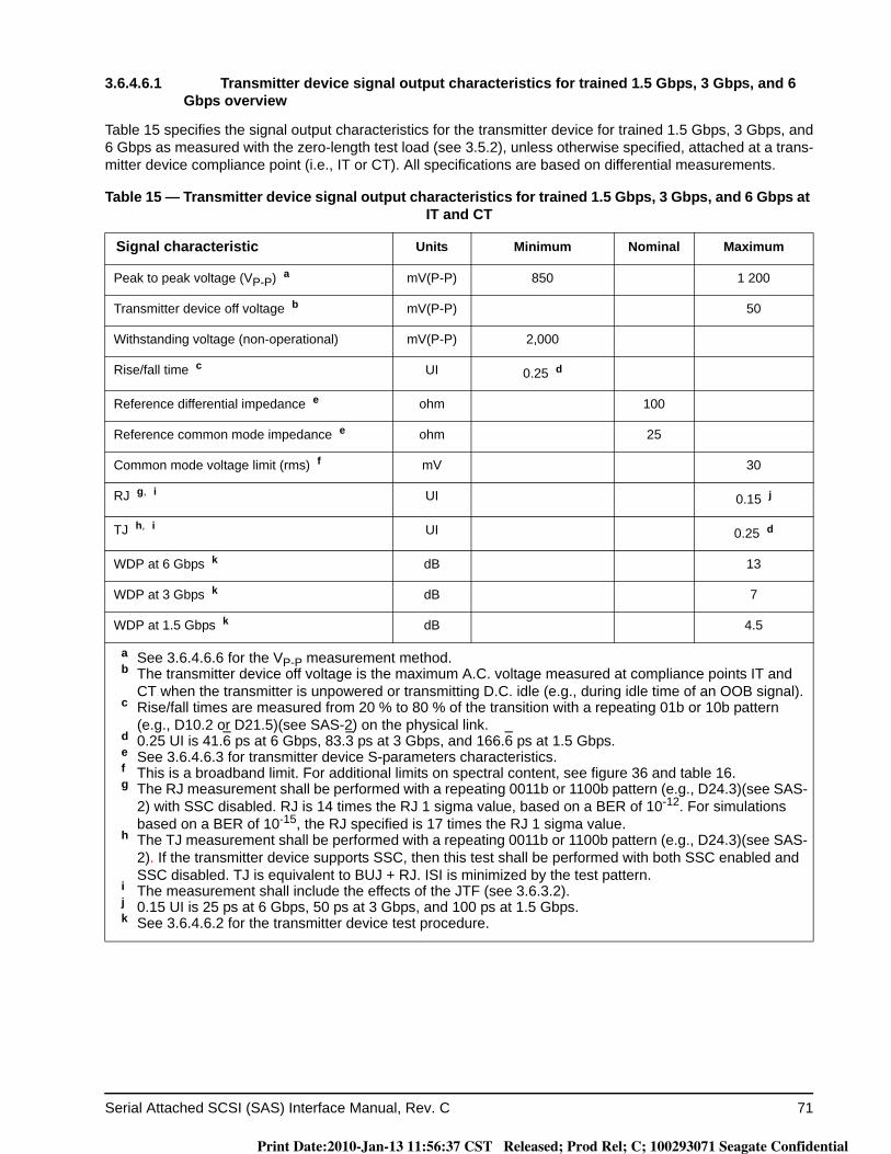
Serial Attached SCSI (SAS) Interface Manual, Rev. C 71
3.6.4.6.1 Transmitter device signal output characteristics for trained 1.5 Gbps, 3 Gbps, and 6 Gbps overview
Table 15 specifies the signal output characteristics for the transmitter device for trained 1.5 Gbps, 3 Gbps, and 6 Gbps as measured with the zero-length test load (see 3.5.2), unless otherwise specified, attached at a trans-mitter device compliance point (i.e., IT or CT). All specifications are based on differential measurements.
Table 15 — Transmitter device signal output characteristics for trained 1.5 Gbps, 3 Gbps, and 6 Gbps at IT and CT
Signal characteristic Units Minimum Nominal Maximum
Peak to peak voltage (VP-P) a mV(P-P) 850 1 200
Transmitter device off voltage b mV(P-P) 50
Withstanding voltage (non-operational) mV(P-P) 2,000
Rise/fall time c UI 0.25 d
Reference differential impedance e ohm 100
Reference common mode impedance e ohm 25
Common mode voltage limit (rms) f mV 30
RJ g, i UI 0.15 j
TJ h, i UI 0.25 d
WDP at 6 Gbps k dB 13
WDP at 3 Gbps k dB 7
WDP at 1.5 Gbps k dB 4.5
a See 3.6.4.6.6 for the VP-P measurement method.b The transmitter device off voltage is the maximum A.C. voltage measured at compliance points IT and
CT when the transmitter is unpowered or transmitting D.C. idle (e.g., during idle time of an OOB signal).c Rise/fall times are measured from 20 % to 80 % of the transition with a repeating 01b or 10b pattern
(e.g., D10.2 or D21.5)(see SAS-2) on the physical link.d 0.25 UI is 41.6 ps at 6 Gbps, 83.3 ps at 3 Gbps, and 166.6 ps at 1.5 Gbps.e See 3.6.4.6.3 for transmitter device S-parameters characteristics.f This is a broadband limit. For additional limits on spectral content, see figure 36 and table 16.g The RJ measurement shall be performed with a repeating 0011b or 1100b pattern (e.g., D24.3)(see SAS-
2) with SSC disabled. RJ is 14 times the RJ 1 sigma value, based on a BER of 10-12. For simulations based on a BER of 10-15, the RJ specified is 17 times the RJ 1 sigma value.
h The TJ measurement shall be performed with a repeating 0011b or 1100b pattern (e.g., D24.3)(see SAS-2). If the transmitter device supports SSC, then this test shall be performed with both SSC enabled and SSC disabled. TJ is equivalent to BUJ + RJ. ISI is minimized by the test pattern.
i The measurement shall include the effects of the JTF (see 3.6.3.2).j 0.15 UI is 25 ps at 6 Gbps, 50 ps at 3 Gbps, and 100 ps at 1.5 Gbps.k See 3.6.4.6.2 for the transmitter device test procedure.
Print Date:2010-Jan-13 11:56:37 CST Released; Prod Rel; C; 100293071 Seagate Confidential

72 Serial Attached SCSI (SAS) Interface Manual, Rev. C
Table 16 defines the transmitter device common mode voltage limit characteristics.
Figure 36 shows the transmitter device common mode voltage limit defined in table 16.
Figure 36. Transmitter device common mode voltage limit
3.6.4.6.2 Transmitter device test procedure
The transmitter device test procedure is as follows:1) attach the transmitter device to a zero-length test load, where its signal output is captured by an oscil-
loscope;2) configure the transmitter device to transmit the SCRAMBLED_0 pattern (see SAS-2);3) configure the transmitter device to minimize DCD and BUJ;4) WDP values computed by SASWDP are influenced by all sources of eye closure including DCD, BUJ,
and ISI, and increased variability in results may occur due to increases in those sources other than ISI.5) capture at least 58 dwords (i.e., 2,320 bits on the physical link). Use averaging to minimize RJ; and6) input the captured pattern into SASWDP simulation (see SAS-2) with the Usage variable set to
‘SAS2_TWDP’.
The WDP value is a characterization of the signal output within the reference receiver device (see 3.6.5.7.3)after equalization.
Table 16 — Transmitter device common mode voltage limit characteristics
Characteristic Reference L a
(dBmV) bN a
(dBmV) b, cS a
(dBmV/decade) bfmin a
(MHz)fmax a
(GHz)
Spectral limit of common mode voltage d
Figure 36 12.7 26.0 13.3 100 6.0
a See SAS-2 for definitions of L, N, S, fmin, and fmax. For this parameter, units of dBmV is used in place of dB.
b For dBmV, the reference level of 0 dBmV is 1 mV (rms). Hence, 0 dBm is 1 mW which is 158 mV (rms) across 25 ohms (i.e., the reference impedance for common mode voltage) which is 20 × log10(158) = +44 dBmV. +26 dBmV is therefore -18 dBm.
c Maximum value at the Nyquist frequency (i.e., 3 GHz) (see figure 36).d The transmitter device common mode voltage shall be measured with a 1 MHz resolution bandwidth
through the range of 100 MHz to 6 GHz with the transmitter device output of CJTPAT (see SAS-2). The end points of the range shall be at the center of the measurement bandwidth.
Note: graph is not to scale
Invalid region
Valid region10 dBmV
20 dBmV
0 dBmV0.1 GHz 0.3 GHz 1 GHz 6 GHz 10 GHz
30 dBmV
VCM
f
12.7 dBmV
Print Date:2010-Jan-13 11:56:37 CST Released; Prod Rel; C; 100293071 Seagate Confidential
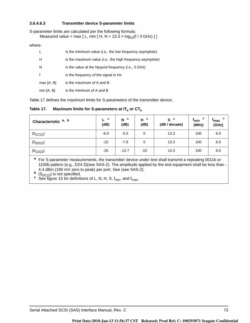
Serial Attached SCSI (SAS) Interface Manual, Rev. C 73
3.6.4.6.3 Transmitter device S-parameter limits
S-parameter limits are calculated per the following formula:Measured value < max [ L, min [ H, N + 13.3 × log10(f / 3 GHz) ] ]
where:
Table 17 defines the maximum limits for S-parameters of the transmitter device.
L is the minimum value (i.e., the low frequency asymptote)
H is the maximum value (i.e., the high frequency asymptote)
N is the value at the Nyquist frequency (i.e., 3 GHz)
f is the frequency of the signal in Hz
max [A, B] is the maximum of A and B
min [A, B] is the minimum of A and B
Table 17. Maximum limits for S-parameters at ITs or CTs
Characteristic a, b L c(dB)
N c(dB)
H c(dB)
S c(dB / decade)
fmin c
(MHz)fmax c
(GHz)
|SCC22| -6.0 -5.0 0 13.3 100 6.0
|SDD22| -10 -7.9 0 13.3 100 6.0
|SCD22| -26 -12.7 -10 13.3 100 6.0
a For S-parameter measurements, the transmitter device under test shall transmit a repeating 0011b or 1100b pattern (e.g., D24.3)(see SAS-2). The amplitude applied by the test equipment shall be less than -4.4 dBm (190 mV zero to peak) per port. See (see SAS-2).
b |SDC22| is not specified.c See figure 15 for definitions of L, N, H, S, fmin, and fmax.
Print Date:2010-Jan-13 11:56:37 CST Released; Prod Rel; C; 100293071 Seagate Confidential
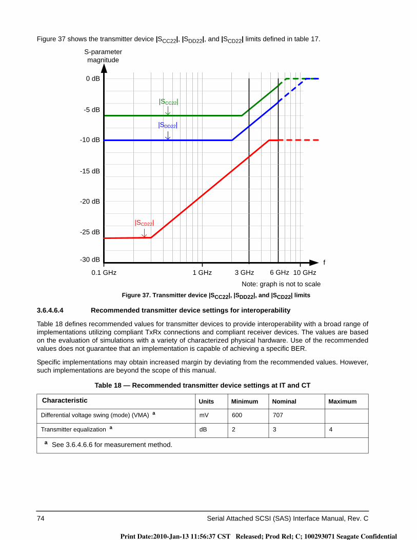
74 Serial Attached SCSI (SAS) Interface Manual, Rev. C
Figure 37 shows the transmitter device |SCC22|, |SDD22|, and |SCD22| limits defined in table 17.
Figure 37. Transmitter device |SCC22|, |SDD22|, and |SCD22| limits
3.6.4.6.4 Recommended transmitter device settings for interoperability
Table 18 defines recommended values for transmitter devices to provide interoperability with a broad range of implementations utilizing compliant TxRx connections and compliant receiver devices. The values are based on the evaluation of simulations with a variety of characterized physical hardware. Use of the recommended values does not guarantee that an implementation is capable of achieving a specific BER.
Specific implementations may obtain increased margin by deviating from the recommended values. However, such implementations are beyond the scope of this manual.
Table 18 — Recommended transmitter device settings at IT and CT
Characteristic Units Minimum Nominal Maximum
Differential voltage swing (mode) (VMA) a mV 600 707
Transmitter equalization a dB 2 3 4
a See 3.6.4.6.6 for measurement method.
0.1 GHz 1 GHz 6 GHz 10 GHz
0 dB
S-parameter magnitude
f3 GHz
|SDD22|
|SCC22|
Note: graph is not to scale
-10 dB
-25 dB
-15 dB
-20 dB
-30 dB
|SCD22|
-5 dB
Print Date:2010-Jan-13 11:56:37 CST Released; Prod Rel; C; 100293071 Seagate Confidential
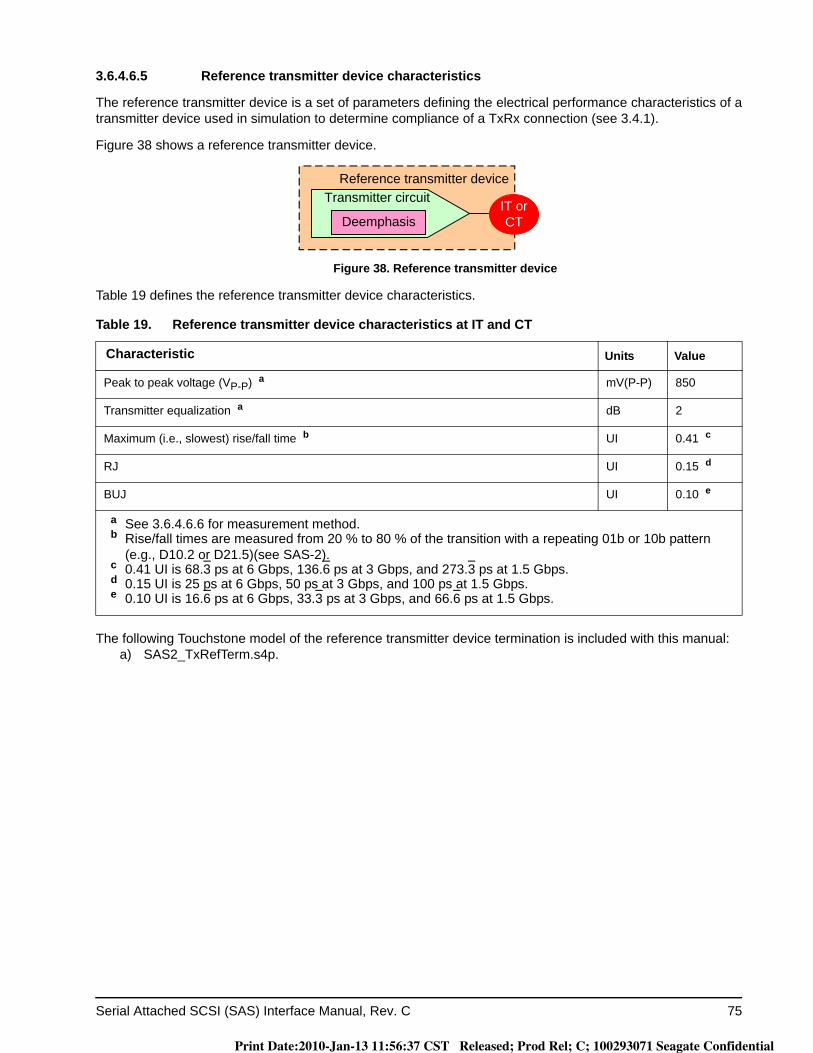
Serial Attached SCSI (SAS) Interface Manual, Rev. C 75
3.6.4.6.5 Reference transmitter device characteristics
The reference transmitter device is a set of parameters defining the electrical performance characteristics of a transmitter device used in simulation to determine compliance of a TxRx connection (see 3.4.1).
Figure 38 shows a reference transmitter device.
Figure 38. Reference transmitter device
Table 19 defines the reference transmitter device characteristics.
The following Touchstone model of the reference transmitter device termination is included with this manual:a) SAS2_TxRefTerm.s4p.
Table 19. Reference transmitter device characteristics at IT and CT
Characteristic Units Value
Peak to peak voltage (VP-P) a mV(P-P) 850
Transmitter equalization a dB 2
Maximum (i.e., slowest) rise/fall time b UI 0.41 c
RJ UI 0.15 d
BUJ UI 0.10 e
a See 3.6.4.6.6 for measurement method.b Rise/fall times are measured from 20 % to 80 % of the transition with a repeating 01b or 10b pattern
(e.g., D10.2 or D21.5)(see SAS-2).c 0.41 UI is 68.3 ps at 6 Gbps, 136.6 ps at 3 Gbps, and 273.3 ps at 1.5 Gbps.d 0.15 UI is 25 ps at 6 Gbps, 50 ps at 3 Gbps, and 100 ps at 1.5 Gbps.e 0.10 UI is 16.6 ps at 6 Gbps, 33.3 ps at 3 Gbps, and 66.6 ps at 1.5 Gbps.
Reference transmitter deviceTransmitter circuit
DeemphasisIT or CT
Print Date:2010-Jan-13 11:56:37 CST Released; Prod Rel; C; 100293071 Seagate Confidential
76 Serial Attached SCSI (SAS) Interface Manual, Rev. C
Figure 39 shows the S-parameters of the reference transmitter device termination model.
Figure 39. Reference transmitter device termination S-parameters
The Touchstone model does not exactly match the |SCC22|, |SDD22|, and |SCD22| limits defined in 3.6.4.6.3 at all frequencies; it is a reasonable approximation for use in simulations. See SAS-2 for a description of how the Touchstone model was created.
3.6.4.6.6 Transmitter equalization, VMA, and VP-P measurement
The transmitter equalization measurement shall be based on the following values:a) VMA: a mode (i.e., the most frequent value of a set of data) measurement; andb) VP-P: a peak-to-peak measurement with a repeating D30.3 pattern (see SAS-2).
The VMA and VP-P measurements shall be made with the transmitter device terminated through the interoper-ability point into a zero length test load (see 3.5.2).
The VMA and VP-P measurements shall be made using an equivalent time sampling scope with a histogram function with the following or an equivalent procedure:
1) calibrate the sampling scope for measurement of a 3 GHz signal; and2) determine VMA and VP-P as shown in figure 40. A sample size of 1,000 minimum, 2,000 maximum histogram hits
for VMA shall be used to determine the values. The histogram is a combination of two histograms: an upper
0.1 GHz 1 GHz 6 GHz 10 GHz
0 dB
S-parameter magnitude
f3 GHz
Note: graph is not to scale
-10 dB
-25 dB
-15 dB
-20 dB
-30 dB
-5 dB|SDD22| limit
|SCC22| limit
|SCD22| limit
|SCCij|
|SDDij|
|SCDij|
Print Date:2010-Jan-13 11:56:37 CST Released; Prod Rel; C; 100293071 Seagate Confidential
Serial Attached SCSI (SAS) Interface Manual, Rev. C 77
histogram for Tx+ and a lower histogram for Tx-. The histograms on the left represent the test pattern signal displayed on the right. VMA and VP-P are determined by adding the values measured for Tx+ and Tx-.
Figure 40. Transmitter equalization measurement
The following formula shall be used to calculate the transmitter equalization value:Transmitter equalization = 20 × log10 (VP-P / VMA) dB
where:
3.6.4.7 Transmitter device signal output characteristics for OOB signals
Transmitter devices supporting SATA shall use SATA Gen1i or Gen2i signal output levels (see SATA) during the first OOB sequence after a power on or hard reset. If the phy does not receive COMINIT within a hot-plug timeout (see 4.6), then the transmitter device shall increase its transmit levels to the OOB signal output levels specified in table 20 and perform the OOB sequence again. If no COMINIT is received within a hot-plug time-out of the second OOB sequence, then the transmitter device shall initiate another OOB sequence using SATA Gen1i or Gen2i signal output levels. The transmitter device shall continue alternating between transmitting COMINIT using SATA Gen1i or Gen2i signal output levels and transmitting COMINIT with SAS signal output levels until the phy receives COMINIT.
If the phy both transmits and receives COMSAS (i.e., a SAS phy or expander phy is attached), then the trans-mitter device shall set its transmit levels to the SAS signal output levels (see 3.6.4.4, 3.6.4.5, and 3.6.4.6) prior to beginning the SAS speed negotiation sequence (see 4.6.2.2). If it had been using SATA Gen1i or Gen2i sig-nal output levels, this mode transition (i.e., output voltage change) may result in a transient (see 3.6.2) during the idle time between COMSAS and the SAS speed negotiation sequence.
If the transmitter device is using SAS signal output levels and the phy does not receive COMSAS (i.e., a SATA phy is attached), then the transmitter device shall set its transmit levels to the SATA Gen1i or Gen2i signal out-put levels and restart the OOB sequence.
Transmitter devices that do not support SATA shall transmit OOB signals using SAS signal output levels.
VP-P is the peak-to-peak value
VMA is the mode value
Transmitter equalization measurement0.6
0.4
0.2
0.0
-0.2
-0.4
-0.6
0 0.5 1.0 1.5 2.0 Occurrences
0.6
0.4
0.2
0.0
-0.2
-0.4
-0.6
Diff
eren
tial V
olta
ge
Diff
eren
tial V
olta
ge
VMA
VP-P
UI
Print Date:2010-Jan-13 11:56:37 CST Released; Prod Rel; C; 100293071 Seagate Confidential
78 Serial Attached SCSI (SAS) Interface Manual, Rev. C
Table 20 defines the transmitter device signal output characteristics for OOB signals.
3.6.5 Receiver device characteristics
3.6.5.1 Receiver device characteristics overview
The receiver device shall operate within the required BER (see 3.4.1) when a signal with valid voltage and tim-ing characteristics is delivered to the receiver device compliance point from a nominal 100 ohm source. The received signal shall be considered valid if it meets the voltage and timing limits specified in table 23 (see 3.6.5.4) for untrained 1.5 Gbps and 3 Gbps and table 27 (see 3.6.5.4) for trained 1.5 Gbps, 3 Gbps, and 6 Gbps.
Additionally, for untrained 1.5 Gbps and 3 Gbps the receiver device shall operate within the required BER when the signal has additional SJ present as specified in table 25 (see 3.6.5.6) with the common-mode signal VCMas specified in table 21 (see 3.6.1). Jitter tolerance for receiver device compliance points is shown in figure 35(see 3.6.3.4). Figure 35 assumes that any external interference occurs prior to the point at which the test is applied. When testing the jitter tolerance capability of a receiver device, the additional 0.1 UI of SJ may be reduced by an amount proportional to the actual externally induced interference between the application point of the test and the input to the receiver device. The additional jitter reduces the eye opening in both voltage and time. For trained 1.5 Gbps, 3 Gbps, and 6 Gbps, the additional jitter and common mode voltage is included in the stressed receiver device jitter tolerance test (see 3.6.5.7.4).
See SAS-2 for a methodology for measuring receiver device signal tolerance.
A receiver device shall provide equivalent performance to the reference receiver device (see 3.6.5.7.3) and shall operate within the required BER when attached to:
a) any transmitter device compliant with this manual (see 3.6.4); and
Table 20. Transmitter device signal output characteristics for OOB signals
Characteristic Units IT CT
Maximum peak to peak voltage (i.e., 2 × Z2 in figure 33) a mV(P-P) 1,600
OOB offset delta b mV ± 25
OOB common mode delta c mV ± 50
Minimum OOB burst amplitude d, if SATA is not supported mV(P-P) 240
Minimum OOB burst amplitude d, if SATA is supported mV(P-P) 240 e, f N/A
a The recommended maximum peak to peak voltage is 1,200 mV(P-P).b The maximum difference in the average differential voltage (D.C. offset) component between the burst
times and the idle times of an OOB signal.c The maximum difference in the average of the common-mode voltage between the burst times and the
idle times of an OOB signal.d With a measurement bandwidth of 4.5 GHz, each signal level during the OOB burst shall exceed the
specified minimum differential amplitude before transitioning to the opposite bit value or before termination of the OOB burst as measured with each test load at IT and CT.
e Amplitude measurement methodologies of SATA and this manual differ. Under conditions of maximum rise/fall time and jitter, eye diagram methodologies used in this manual may indicate less signal amplitude than the technique specified by SATA. Implementers of designs supporting SATA are required to ensure interoperability and should perform additional system characterization with an eye diagram methodology using SATA devices.
f The OOB burst contains either 1.5 Gbps D24.3 characters, 1.5 Gbps ALIGN (0) primitives, or 3 Gbps ALIGN (0) primitives.
Print Date:2010-Jan-13 11:56:37 CST Released; Prod Rel; C; 100293071 Seagate Confidential
Serial Attached SCSI (SAS) Interface Manual, Rev. C 79
b) any TxRx connection compliant with this manual (see 3.4).
3.6.5.2 Receiver device A.C. coupling requirements
A.C. coupling requirements for receiver devices are as follows:a) all receiver devices (i.e., attached to IR or CR compliance points) shall be A.C. coupled to the inter-
connect through a receive network.
3.6.5.3 Receiver device general electrical characteristics
Table 21 defines the receiver device general electrical characteristics.
Table 21. Receiver device general electrical characteristics
Characteristic Units 1.5 Gbps 3 Gbps 6 Gbps
Physical link rate long-term tolerance at IR if SATA is not supported
ppm ± 100
Physical link rate long-term tolerance at IR if SATA is sup-ported
ppm ± 350
Physical link rate SSC modulation tolerance at IR ppm See table 37 in 3.6.6.3
Maximum receiver device transients a V ± 1.2
Minimum receiver A.C. common-mode voltage tolerance VCM
bmV(P-P) 150
Receiver A.C. common-mode frequency tolerance range FCM
bMHz 2 to 200
a See 3.6.2 for transient test circuits and conditions.b Receiver devices shall tolerate sinusoidal common-mode noise components within the peak-to-peak
amplitude (VCM) and the frequency range (FCM).
Print Date:2010-Jan-13 11:56:37 CST Released; Prod Rel; C; 100293071 Seagate Confidential
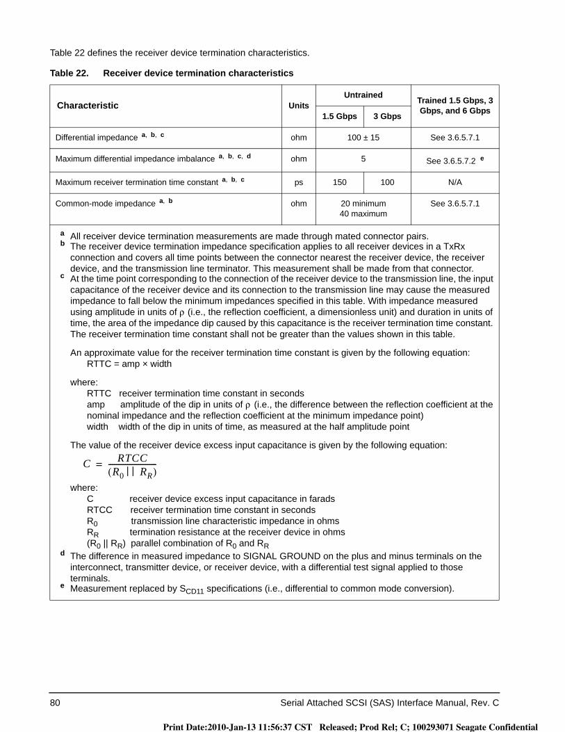
80 Serial Attached SCSI (SAS) Interface Manual, Rev. C
Table 22 defines the receiver device termination characteristics.
Table 22. Receiver device termination characteristics
Characteristic UnitsUntrained Trained 1.5 Gbps, 3
Gbps, and 6 Gbps1.5 Gbps 3 Gbps
Differential impedance a, b, c ohm 100 ± 15 See 3.6.5.7.1
Maximum differential impedance imbalance a, b, c, d ohm 5 See 3.6.5.7.2 e
Maximum receiver termination time constant a, b, c ps 150 100 N/A
Common-mode impedance a, b ohm 20 minimum40 maximum
See 3.6.5.7.1
a All receiver device termination measurements are made through mated connector pairs.b The receiver device termination impedance specification applies to all receiver devices in a TxRx
connection and covers all time points between the connector nearest the receiver device, the receiver device, and the transmission line terminator. This measurement shall be made from that connector.
c At the time point corresponding to the connection of the receiver device to the transmission line, the input capacitance of the receiver device and its connection to the transmission line may cause the measured impedance to fall below the minimum impedances specified in this table. With impedance measured using amplitude in units of ρ (i.e., the reflection coefficient, a dimensionless unit) and duration in units of time, the area of the impedance dip caused by this capacitance is the receiver termination time constant. The receiver termination time constant shall not be greater than the values shown in this table.
An approximate value for the receiver termination time constant is given by the following equation:RTTC = amp × width
where:RTTC receiver termination time constant in secondsamp amplitude of the dip in units of ρ (i.e., the difference between the reflection coefficient at thenominal impedance and the reflection coefficient at the minimum impedance point)width width of the dip in units of time, as measured at the half amplitude point
The value of the receiver device excess input capacitance is given by the following equation:
where:C receiver device excess input capacitance in faradsRTCC receiver termination time constant in secondsR0 transmission line characteristic impedance in ohmsRR termination resistance at the receiver device in ohms(R0 || RR) parallel combination of R0 and RR
d The difference in measured impedance to SIGNAL GROUND on the plus and minus terminals on the interconnect, transmitter device, or receiver device, with a differential test signal applied to those terminals.
e Measurement replaced by SCD11 specifications (i.e., differential to common mode conversion).
C RTCCR0 RR| |( )
--------------------------=
Print Date:2010-Jan-13 11:56:37 CST Released; Prod Rel; C; 100293071 Seagate Confidential
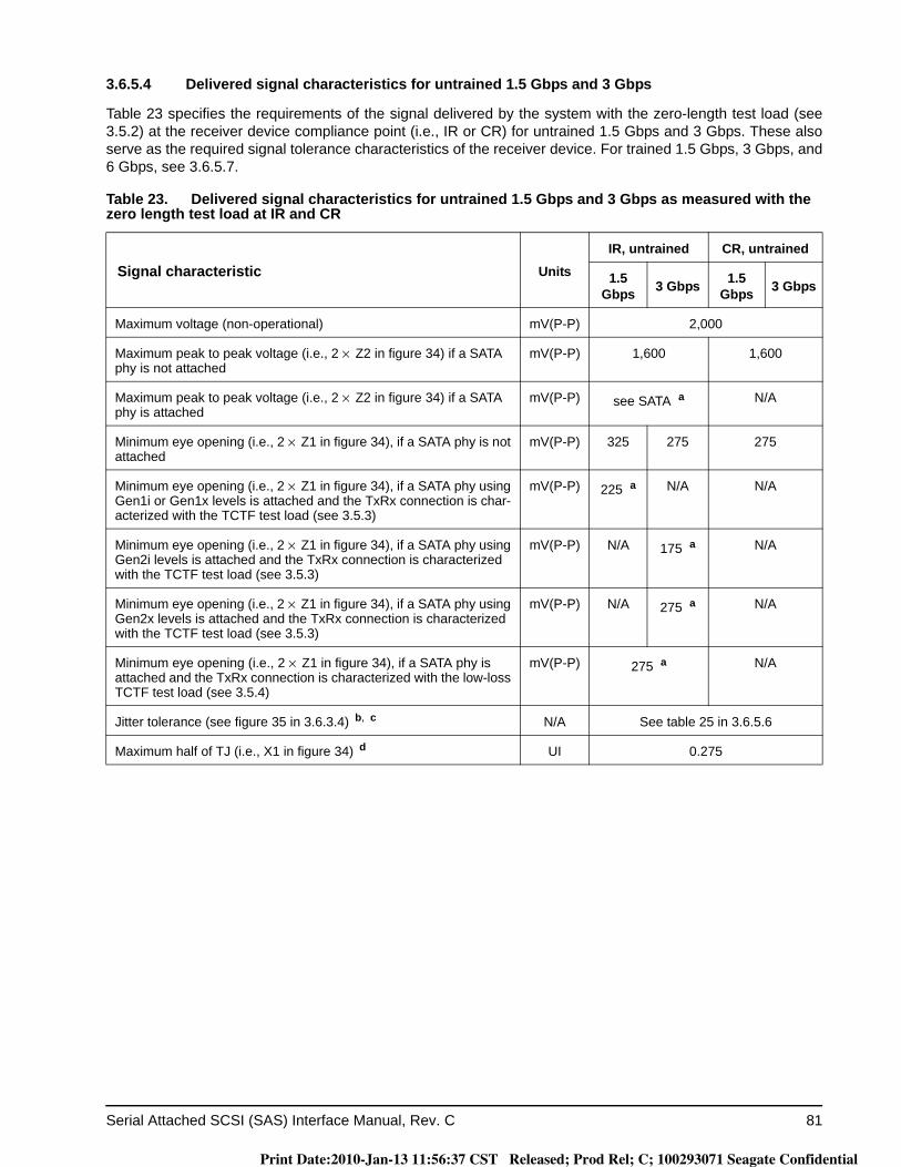
Serial Attached SCSI (SAS) Interface Manual, Rev. C 81
3.6.5.4 Delivered signal characteristics for untrained 1.5 Gbps and 3 Gbps
Table 23 specifies the requirements of the signal delivered by the system with the zero-length test load (see 3.5.2) at the receiver device compliance point (i.e., IR or CR) for untrained 1.5 Gbps and 3 Gbps. These also serve as the required signal tolerance characteristics of the receiver device. For trained 1.5 Gbps, 3 Gbps, and 6 Gbps, see 3.6.5.7.
Table 23. Delivered signal characteristics for untrained 1.5 Gbps and 3 Gbps as measured with the zero length test load at IR and CR
Signal characteristic UnitsIR, untrained CR, untrained
1.5 Gbps 3 Gbps 1.5
Gbps 3 Gbps
Maximum voltage (non-operational) mV(P-P) 2,000
Maximum peak to peak voltage (i.e., 2 × Z2 in figure 34) if a SATA phy is not attached
mV(P-P) 1,600 1,600
Maximum peak to peak voltage (i.e., 2 × Z2 in figure 34) if a SATA phy is attached
mV(P-P) see SATA a N/A
Minimum eye opening (i.e., 2 × Z1 in figure 34), if a SATA phy is not attached
mV(P-P) 325 275 275
Minimum eye opening (i.e., 2 × Z1 in figure 34), if a SATA phy using Gen1i or Gen1x levels is attached and the TxRx connection is char-acterized with the TCTF test load (see 3.5.3)
mV(P-P) 225 a N/A N/A
Minimum eye opening (i.e., 2 × Z1 in figure 34), if a SATA phy using Gen2i levels is attached and the TxRx connection is characterized with the TCTF test load (see 3.5.3)
mV(P-P) N/A 175 a N/A
Minimum eye opening (i.e., 2 × Z1 in figure 34), if a SATA phy using Gen2x levels is attached and the TxRx connection is characterized with the TCTF test load (see 3.5.3)
mV(P-P) N/A 275 a N/A
Minimum eye opening (i.e., 2 × Z1 in figure 34), if a SATA phy is attached and the TxRx connection is characterized with the low-loss TCTF test load (see 3.5.4)
mV(P-P) 275 a N/A
Jitter tolerance (see figure 35 in 3.6.3.4) b, c N/A See table 25 in 3.6.5.6
Maximum half of TJ (i.e., X1 in figure 34) d UI 0.275
Print Date:2010-Jan-13 11:56:37 CST Released; Prod Rel; C; 100293071 Seagate Confidential

82 Serial Attached SCSI (SAS) Interface Manual, Rev. C
Center of bit time (i.e., X2 in figure 34) UI 0.50
Maximum intra-pair skew e ps 80 75 80 75
a Amplitude measurement methodologies of SATA and this manual differ. Under conditions of maximum rise/fall time and jitter, eye diagram methodologies used in this manual may indicate less signal amplitude than the technique specified by SATA. Implementers of designs supporting SATA are required to ensure interoperability and should perform additional system characterization with an eye diagram methodology using SATA devices.
b The value for X1 applies at a TJ probability of 10-12. At this level of probability direct visual comparison between the mask and actual signals is not a valid method for determining compliance with the jitter requirements.
c SSC shall be enabled if the receiver device supports being attached to SATA. Jitter setup shall be performed prior to application of SSC.
d The value for X1 shall be half the value given for TJ in table 24. When SSC is disabled, the test or analysis shall include the effects of a single pole high-pass frequency-weighting function that progressively attenuates jitter at 20 dB/decade below a frequency of (fbaud / 1,667).
e The intra-pair skew measurement shall be made at the midpoint of the transition with a repeating 01b or 10b pattern (e.g., D10.2 or D21.5)(see SAS-2) on the physical link. The same stable trigger, coherent to the data stream, shall be used for both the Rx+ and Rx- signals. Intra-pair skew is defined as the time difference between the means of the midpoint crossing times of the Rx+ signal and the Rx- signal at the probe points.
Table 23. Delivered signal characteristics for untrained 1.5 Gbps and 3 Gbps as measured with the zero length test load at IR and CR
Signal characteristic UnitsIR, untrained CR, untrained
1.5 Gbps 3 Gbps 1.5
Gbps 3 Gbps
Print Date:2010-Jan-13 11:56:37 CST Released; Prod Rel; C; 100293071 Seagate Confidential
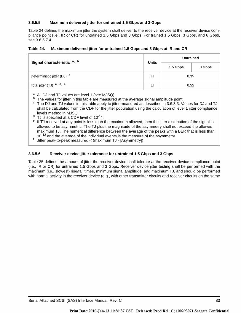
Serial Attached SCSI (SAS) Interface Manual, Rev. C 83
3.6.5.5 Maximum delivered jitter for untrained 1.5 Gbps and 3 Gbps
Table 24 defines the maximum jitter the system shall deliver to the receiver device at the receiver device com-pliance point (i.e., IR or CR) for untrained 1.5 Gbps and 3 Gbps. For trained 1.5 Gbps, 3 Gbps, and 6 Gbps, see 3.6.5.7.4.
3.6.5.6 Receiver device jitter tolerance for untrained 1.5 Gbps and 3 Gbps
Table 25 defines the amount of jitter the receiver device shall tolerate at the receiver device compliance point (i.e., IR or CR) for untrained 1.5 Gbps and 3 Gbps. Receiver device jitter testing shall be performed with the maximum (i.e., slowest) rise/fall times, minimum signal amplitude, and maximum TJ, and should be performed with normal activity in the receiver device (e.g., with other transmitter circuits and receiver circuits on the same
Table 24. Maximum delivered jitter for untrained 1.5 Gbps and 3 Gbps at IR and CR
Signal characteristic a, b UnitsUntrained
1.5 Gbps 3 Gbps
Deterministic jitter (DJ) c UI 0.35
Total jitter (TJ) c, d, e UI 0.55
a All DJ and TJ values are level 1 (see MJSQ).b The values for jitter in this table are measured at the average signal amplitude point.c The DJ and TJ values in this table apply to jitter measured as described in 3.6.3.3. Values for DJ and TJ
shall be calculated from the CDF for the jitter population using the calculation of level 1 jitter compliance levels method in MJSQ.
d TJ is specified at a CDF level of 10-12.e If TJ received at any point is less than the maximum allowed, then the jitter distribution of the signal is
allowed to be asymmetric. The TJ plus the magnitude of the asymmetry shall not exceed the allowed maximum TJ. The numerical difference between the average of the peaks with a BER that is less than 10-12 and the average of the individual events is the measure of the asymmetry.
f Jitter peak-to-peak measured < (maximum TJ - |Asymmetry|)
Print Date:2010-Jan-13 11:56:37 CST Released; Prod Rel; C; 100293071 Seagate Confidential
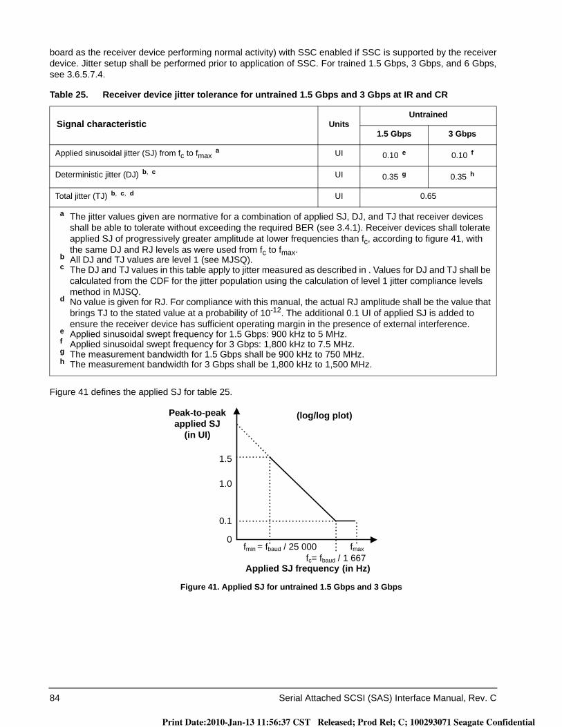
84 Serial Attached SCSI (SAS) Interface Manual, Rev. C
board as the receiver device performing normal activity) with SSC enabled if SSC is supported by the receiver device. Jitter setup shall be performed prior to application of SSC. For trained 1.5 Gbps, 3 Gbps, and 6 Gbps, see 3.6.5.7.4.
Figure 41 defines the applied SJ for table 25.
Figure 41. Applied SJ for untrained 1.5 Gbps and 3 Gbps
Table 25. Receiver device jitter tolerance for untrained 1.5 Gbps and 3 Gbps at IR and CR
Signal characteristic UnitsUntrained
1.5 Gbps 3 Gbps
Applied sinusoidal jitter (SJ) from fc to fmax a UI 0.10 e 0.10 f
Deterministic jitter (DJ) b, c UI 0.35 g 0.35 h
Total jitter (TJ) b, c, d UI 0.65
a The jitter values given are normative for a combination of applied SJ, DJ, and TJ that receiver devices shall be able to tolerate without exceeding the required BER (see 3.4.1). Receiver devices shall tolerate applied SJ of progressively greater amplitude at lower frequencies than fc, according to figure 41, with the same DJ and RJ levels as were used from fc to fmax.b All DJ and TJ values are level 1 (see MJSQ).
c The DJ and TJ values in this table apply to jitter measured as described in . Values for DJ and TJ shall be calculated from the CDF for the jitter population using the calculation of level 1 jitter compliance levels method in MJSQ.
d No value is given for RJ. For compliance with this manual, the actual RJ amplitude shall be the value that brings TJ to the stated value at a probability of 10-12. The additional 0.1 UI of applied SJ is added to ensure the receiver device has sufficient operating margin in the presence of external interference.
e Applied sinusoidal swept frequency for 1.5 Gbps: 900 kHz to 5 MHz.f Applied sinusoidal swept frequency for 3 Gbps: 1,800 kHz to 7.5 MHz.g The measurement bandwidth for 1.5 Gbps shall be 900 kHz to 750 MHz.h The measurement bandwidth for 3 Gbps shall be 1,800 kHz to 1,500 MHz.
fmin = fbaud / 25 000 fmax
Peak-to-peak applied SJ
(in UI)
1.5
0
0.1
1.0
fc= fbaud / 1 667
(log/log plot)
Applied SJ frequency (in Hz)
Print Date:2010-Jan-13 11:56:37 CST Released; Prod Rel; C; 100293071 Seagate Confidential
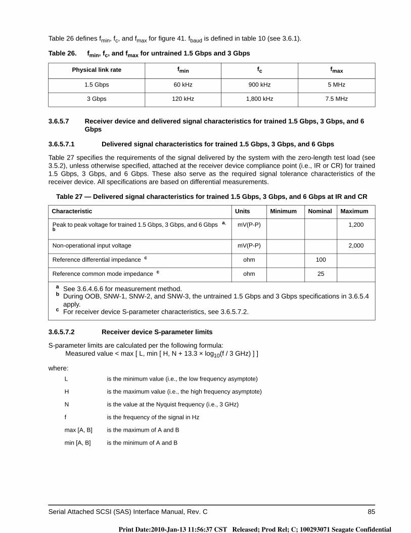
Serial Attached SCSI (SAS) Interface Manual, Rev. C 85
Table 26 defines fmin, fc, and fmax for figure 41. fbaud is defined in table 10 (see 3.6.1).
3.6.5.7 Receiver device and delivered signal characteristics for trained 1.5 Gbps, 3 Gbps, and 6 Gbps
3.6.5.7.1 Delivered signal characteristics for trained 1.5 Gbps, 3 Gbps, and 6 Gbps
Table 27 specifies the requirements of the signal delivered by the system with the zero-length test load (see 3.5.2), unless otherwise specified, attached at the receiver device compliance point (i.e., IR or CR) for trained 1.5 Gbps, 3 Gbps, and 6 Gbps. These also serve as the required signal tolerance characteristics of the receiver device. All specifications are based on differential measurements.
3.6.5.7.2 Receiver device S-parameter limits
S-parameter limits are calculated per the following formula:Measured value < max [ L, min [ H, N + 13.3 × log10(f / 3 GHz) ] ]
where:
Table 26. fmin, fc, and fmax for untrained 1.5 Gbps and 3 Gbps
Physical link rate fmin fc fmax
1.5 Gbps 60 kHz 900 kHz 5 MHz
3 Gbps 120 kHz 1,800 kHz 7.5 MHz
Table 27 — Delivered signal characteristics for trained 1.5 Gbps, 3 Gbps, and 6 Gbps at IR and CR
Characteristic Units Minimum Nominal Maximum
Peak to peak voltage for trained 1.5 Gbps, 3 Gbps, and 6 Gbps a, b
mV(P-P) 1,200
Non-operational input voltage mV(P-P) 2,000
Reference differential impedance c ohm 100
Reference common mode impedance c ohm 25
a See 3.6.4.6.6 for measurement method.b During OOB, SNW-1, SNW-2, and SNW-3, the untrained 1.5 Gbps and 3 Gbps specifications in 3.6.5.4
apply.c For receiver device S-parameter characteristics, see 3.6.5.7.2.
L is the minimum value (i.e., the low frequency asymptote)
H is the maximum value (i.e., the high frequency asymptote)
N is the value at the Nyquist frequency (i.e., 3 GHz)
f is the frequency of the signal in Hz
max [A, B] is the maximum of A and B
min [A, B] is the minimum of A and B
Print Date:2010-Jan-13 11:56:37 CST Released; Prod Rel; C; 100293071 Seagate Confidential
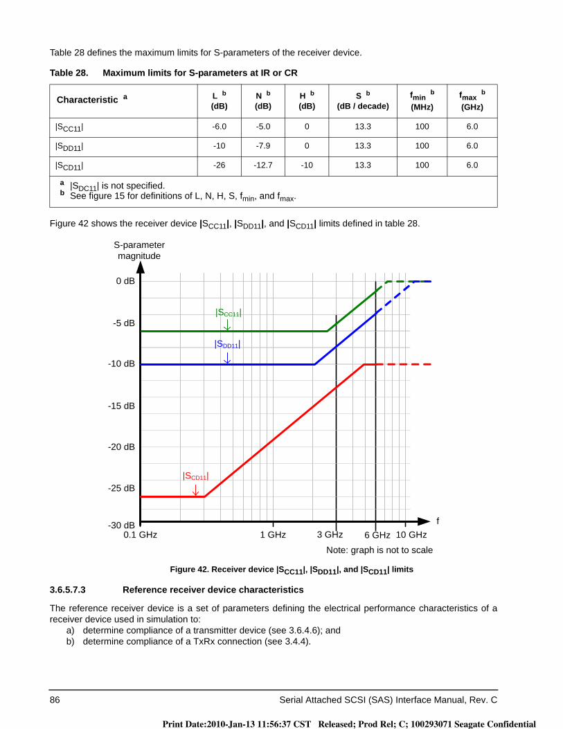
86 Serial Attached SCSI (SAS) Interface Manual, Rev. C
Table 28 defines the maximum limits for S-parameters of the receiver device.
Figure 42 shows the receiver device |SCC11|, |SDD11|, and |SCD11| limits defined in table 28.
Figure 42. Receiver device |SCC11|, |SDD11|, and |SCD11| limits
3.6.5.7.3 Reference receiver device characteristics
The reference receiver device is a set of parameters defining the electrical performance characteristics of a receiver device used in simulation to:
a) determine compliance of a transmitter device (see 3.6.4.6); andb) determine compliance of a TxRx connection (see 3.4.4).
Table 28. Maximum limits for S-parameters at IR or CR
Characteristic a L b(dB)
N b(dB)
H b(dB)
S b(dB / decade)
fmin b
(MHz)fmax b
(GHz)
|SCC11| -6.0 -5.0 0 13.3 100 6.0
|SDD11| -10 -7.9 0 13.3 100 6.0
|SCD11| -26 -12.7 -10 13.3 100 6.0
a |SDC11| is not specified.b See figure 15 for definitions of L, N, H, S, fmin, and fmax.
0.1 GHz 1 GHz 6 GHz 10 GHz
0 dB
S-parameter magnitude
f3 GHz
Note: graph is not to scale
-10 dB
-25 dB
-15 dB
-20 dB
-30 dB
-5 dB
|SDD11|
|SCC11|
|SCD11|
Print Date:2010-Jan-13 11:56:37 CST Released; Prod Rel; C; 100293071 Seagate Confidential
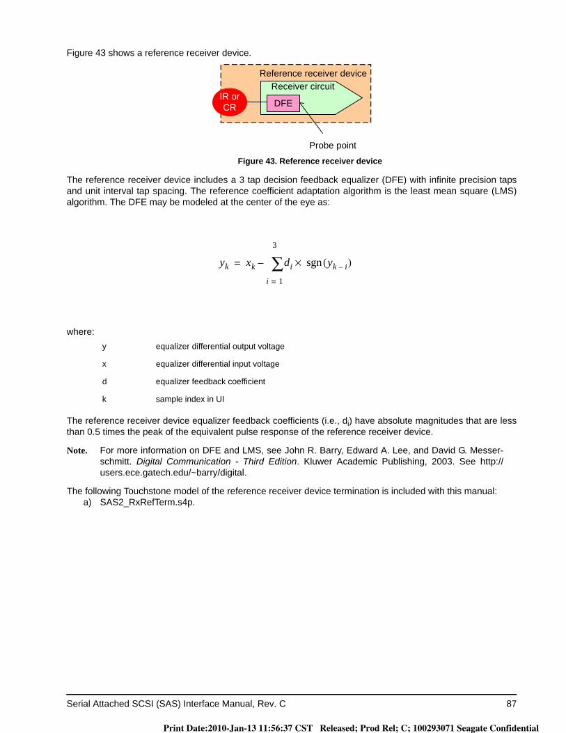
Serial Attached SCSI (SAS) Interface Manual, Rev. C 87
Figure 43 shows a reference receiver device.
Figure 43. Reference receiver device
The reference receiver device includes a 3 tap decision feedback equalizer (DFE) with infinite precision taps and unit interval tap spacing. The reference coefficient adaptation algorithm is the least mean square (LMS) algorithm. The DFE may be modeled at the center of the eye as:
where:
The reference receiver device equalizer feedback coefficients (i.e., di) have absolute magnitudes that are less than 0.5 times the peak of the equivalent pulse response of the reference receiver device.
Note. For more information on DFE and LMS, see John R. Barry, Edward A. Lee, and David G. Messer-schmitt. Digital Communication - Third Edition. Kluwer Academic Publishing, 2003. See http://users.ece.gatech.edu/~barry/digital.
The following Touchstone model of the reference receiver device termination is included with this manual:a) SAS2_RxRefTerm.s4p.
y equalizer differential output voltage
x equalizer differential input voltage
d equalizer feedback coefficient
k sample index in UI
Reference receiver deviceReceiver circuit
DFEIR or CR
Probe point
yk xk di
i 1=
3
∑ yk i–( )sgn×–=
Print Date:2010-Jan-13 11:56:37 CST Released; Prod Rel; C; 100293071 Seagate Confidential
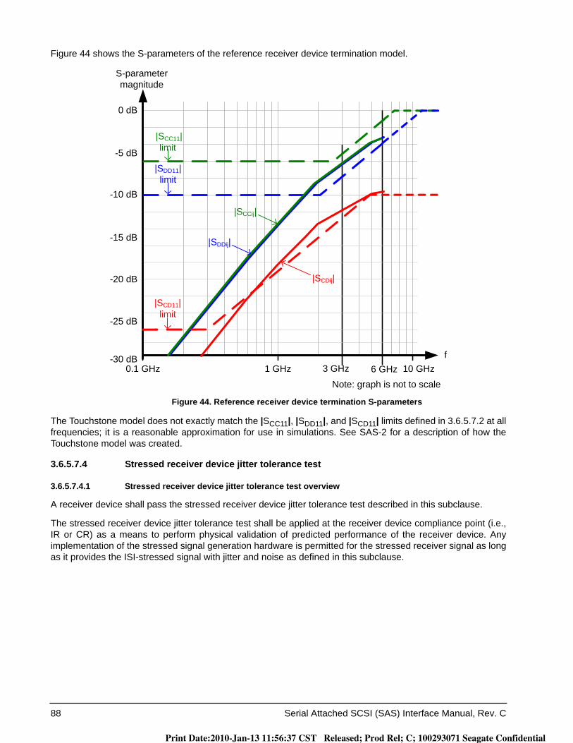
88 Serial Attached SCSI (SAS) Interface Manual, Rev. C
Figure 44 shows the S-parameters of the reference receiver device termination model.
Figure 44. Reference receiver device termination S-parameters
The Touchstone model does not exactly match the |SCC11|, |SDD11|, and |SCD11| limits defined in 3.6.5.7.2 at all frequencies; it is a reasonable approximation for use in simulations. See SAS-2 for a description of how the Touchstone model was created.
3.6.5.7.4 Stressed receiver device jitter tolerance test
3.6.5.7.4.1 Stressed receiver device jitter tolerance test overview
A receiver device shall pass the stressed receiver device jitter tolerance test described in this subclause.
The stressed receiver device jitter tolerance test shall be applied at the receiver device compliance point (i.e., IR or CR) as a means to perform physical validation of predicted performance of the receiver device. Any implementation of the stressed signal generation hardware is permitted for the stressed receiver signal as long as it provides the ISI-stressed signal with jitter and noise as defined in this subclause.
0.1 GHz 1 GHz 6 GHz 10 GHz
0 dB
S-parameter magnitude
f3 GHz
Note: graph is not to scale
-10 dB
-25 dB
-15 dB
-20 dB
-30 dB
-5 dB|SDD11| limit
|SCC11| limit
|SCD11| limit
|SCCij|
|SDDij|
|SCDij|
Print Date:2010-Jan-13 11:56:37 CST Released; Prod Rel; C; 100293071 Seagate Confidential
Serial Attached SCSI (SAS) Interface Manual, Rev. C 89
Figure 45 shows the block diagram of the stressed receiver device jitter tolerance test.
Figure 45. Stressed receiver device jitter tolerance test block diagram
The ISI generator shall be representative of, and at least as stressful as, the reference transmitter test load (see 3.5.5).
Note. The reference transmitter test load (see 3.5.5), with a nominal |SDD21| of -15 dB at (fbaud / 2), may be used as a component of the ISI generator.
The receiver device under test demonstrates its ability to compensate for channel intersymbol interference (ISI) representative of the reference transmitter test load (see 3.5.5) while subjected to the budgeted jitter and crosstalk sources.
Test equipment
Crosstalk source Clock source
+Receiver device
under testError
detector
Oscilloscope(for calibration)
ISI generatorDeemphasis generator
Pattern generator
IR or CRA
Clock source
+ Noise source
Variable SJ source
RJ
SJ
Print Date:2010-Jan-13 11:56:37 CST Released; Prod Rel; C; 100293071 Seagate Confidential
90 Serial Attached SCSI (SAS) Interface Manual, Rev. C
Table 29 defines the stressed receiver device jitter tolerance test characteristics. Unless otherwise noted, char-acteristics are measured at IR or CR in figure 45.
Table 29. Stressed receiver device jitter tolerance test characteristics
Characteristic Units Minimum Nominal Maximum Reference
Tx peak to peak voltage a mV(P-P) 850 3.6.4.6.1
Transmitter equalization a dB 2 3.6.4.6.6
Tx RJ b, c, d UI 0.135 f 0.150 g 0.165 h 3.6.4.6.1
Tx SJ c UI See figure 47 and figure 48 3.6.5.7.4.5
WDP at 6 Gbps b, l dB 13 14.5
WDP at 3 Gbps b, l dB 7 8.5
WDP at 1.5 Gbps b, l dB 4.5 6
D24.3 eye opening b, m mV(P-P) 200 215 230
NEXT offset frequency n, o ppm 2,500
Total crosstalk amplitude o mVrms 4
Receiver device configuration p
a For a characteristic with only a nominal value, the test setup shall be configured to be as close to that value as possible while still complying with other characteristics in this table.
b For characteristics with minimum and maximum values, the test setup shall be configured to be within the range specified by the minimum and maximum values. The range shall not be used to define corner test conditions required for compliance.
c Measured at point A in figure 45.d Measured after application of the JTF (see 3.6.3.2).e 0.25 UI is 41.6 ps at 6 Gbps, 83.3 ps at 3 Gbps, and 166.6 ps at 1.5 Gbps.f 0.135 UI is 22.5 ps at 6 Gbps, 45 ps at 3 Gbps, and 90 ps at 1.5 Gbps.g 0.150 UI is 25 ps at 6 Gbps, 50 ps at 3 Gbps, and 100 ps at 1.5 Gbps.h 0.165 UI is 27.5 ps at 6 Gbps, 55 ps at 3 Gbps, and 110 ps at 1.5 Gbps.i 0.09 UI is 15 ps at 6 Gbps, 30 ps at 3 Gbps, and 60 ps at 1.5 Gbps.j 0.10 UI is 16.6 ps at 6 Gbps, 33.3 ps at 3 Gbps, and 66.6 ps at 1.5 Gbps.k 0.11 UI is 18.3 ps at 6 Gbps, 36.6 ps at 3 Gbps, and 73.3 ps at 1.5 Gbps.l This value is obtained by simulation with SASWDP (see SAS-2). BUJ and RJ shall be minimized for
WDP simulations. The WDP value is a characterization of the signal output within the reference receiver device (see 3.6.5.7.3) after equalization.
m The D24.3 delivered eye opening pertains to the delivered signal at IR or CR. Figure 46 defines this value in an eye diagram.
n The NEXT source may use SSC modulation rather than have a fixed offset frequency.o Observed with a histogram of at least 1,000 samples. Additional pseudo-random crosstalk shall be
added, if needed, to meet the total crosstalk amplitude specification.p All transmitter devices and receiver devices adjacent to the receiver device under test shall be active with
representative traffic with their maximum amplitude and maximum frequency of operation.
Print Date:2010-Jan-13 11:56:37 CST Released; Prod Rel; C; 100293071 Seagate Confidential
Serial Attached SCSI (SAS) Interface Manual, Rev. C 91
Figure 46 shows the stressed receiver device jitter tolerance test D24.3 eye opening.
Figure 46. Stressed receiver device jitter tolerance test D24.3 eye opening
3.6.5.7.4.2 Stressed receiver device jitter tolerance test procedure
The stressed receiver device jitter tolerance test procedure is as follows:1) calibrate the test equipment and ISI generator as specifed in 3.6.5.7.4.3;2) calibrate the crosstalk source as specified in 3.6.5.7.4.4;3) attach the test equipment and ISI generator and the crosstalk source to the receiver device under test;4) configure the applied SJ as specified in 3.6.5.7.4.5;5) configure the pattern generator to transmit CJTPAT (see SAS-2); and6) ensure that the receiver device under test has a BER that is less than 10-12 with a confidence level of 95 %.
0.15
0.10
0.05
0.00
-0.05
-0.10
-0.15
0 0.2 0.4 0.6 0.8 1.0 UI
Diff
eren
tial V
olta
ge
D24.3 eye opening
Print Date:2010-Jan-13 11:56:37 CST Released; Prod Rel; C; 100293071 Seagate Confidential

92 Serial Attached SCSI (SAS) Interface Manual, Rev. C
Table 30 defines the number of bits that shall be received with a certain number of errors to have a confidence level of 95 % that the BER is less than 10-12.
3.6.5.7.4.3 Test equipment and ISI generator calibration
The test equipment and ISI generator calibration procedure is as follows:1) ensure that the ISI generator has an |SDD21| comparable to that of the reference transmitter test load
(see 3.5.5). |SDD21| delivered by the ISI generator shall be measured by observing the D24.3 eye opening at IR or CR as defined in table 29;
2) attach the test equipment and ISI generator to a zero-length test load, where its signal output is captured by an oscilloscope;
3) disable the crosstalk source;4) disable the variable SJ source and the random noise source;5) WDP values computed by SASWDP are influenced by all sources of eye closure including DCD, BUJ, and ISI,
and increased variability in results may occur due to increases in those sources other than ISI.6) configure the pattern generator to transmit the SCRAMBLED_0 pattern (see SAS-2);7) capture at least 58 dwords (i.e., 2,320 bits on the physical link). Waveform averaging shall be used to minimize the
impact of measurement noise and jitter on the WDP calculations;8) input the captured pattern into SASWDP simulation (see SAS-2) with the Usage variable set to ‘SAS2_LDP’; and9) adjust the ISI generator until the WDP is within the range defined in table 29 (see 3.6.5.7.4.1).
3.6.5.7.4.4 Crosstalk source calibration1) The crosstalk source calibration procedure is as follows:2) attach the test equipment and ISI generator and the crosstalk source to a zero-length test load, where its signal
output is captured by an oscilloscope;3) disable the pattern generator;4) enable the crosstalk source;5) set the center frequency of the crosstalk source to be frequency offset from the pattern generator to sweep all
potential relative phase alignments between the crosstalk source and the signal from the ISI generator;6) generate a histograph of the signal delivered to the test equipment; and7) adjust the crosstalk source until the crosstalk amplitude complies with table 29 (see 3.6.5.7.4.1).
Table 30. Number of bits received per number of errors for desired BER
Number of errors Number of bits
0 3.00 × 10¹²
1 4.74 × 10¹²
2 6.30 × 10¹²
3 7.75 × 10¹²
4 9.15 × 10¹²
5 1.05 × 10¹³
Print Date:2010-Jan-13 11:56:37 CST Released; Prod Rel; C; 100293071 Seagate Confidential

Serial Attached SCSI (SAS) Interface Manual, Rev. C 93
3.6.5.7.4.5 Applied SJ
Figure 47 defines the applied SJ for trained receiver devices that do not support SSC.
Figure 47. Applied SJ for trained 1.5 Gbps, 3 Gbps, and 6 Gbps without SSC support
Table 31 defines fmin, fc, and fmax for figure 47. fbaud is defined in table 10 (see 3.6.1).
Figure 48 defines the applied SJ for trained receiver devices that support SSC.
Figure 48. Applied SJ for trained 1.5 Gbps, 3 Gbps, and 6 Gbps with SSC support
Table 31. fmin, fc, and fmax for trained 1.5 Gbps, 3 Gbps, and 6 Gbps without SSC support
Physical link rate fmin fc fmax
1.5 Gbps 60 kHz 890 kHz 5 MHz
3 Gbps 120 kHz 1,800 kHz 7.5 MHz
6 Gbps 240 kHz 3,600 kHz 15 MHz
fmin = fbaud / 25,000 fmax
(log/log plot)Peak-to-peak applied SJ
(in UI)
1.5
0
0.1
Applied SJ frequency (in Hz)
1.0
fc= fbaud / 1 667
fmin fc
Peak-to-peak applied SJ
(in UI)
SJlf
0
0.1
1.0
fmax
(log/log plot)
Applied SJ frequency (in Hz)
Print Date:2010-Jan-13 11:56:37 CST Released; Prod Rel; C; 100293071 Seagate Confidential
94 Serial Attached SCSI (SAS) Interface Manual, Rev. C
Table 32 defines fmin, fc, fmax, and SJlf for figure 48.
3.6.5.8 Delivered signal characteristics for OOB signals
Table 33 defines the amplitude requirements of the OOB signal delivered by the system with the zero-length test load (see 3.5.2) at the receiver device compliance point (i.e., IR or CR). These also serve as the required signal tolerance characteristics of the receiver device.
3.6.6 Spread spectrum clocking (SSC)
3.6.6.1 SSC overview
Spread spectrum clocking (SSC) is the technique of modulating the operating frequency of a transmitted signal to reduce the measured peak amplitude of radiated emissions.
Phys transmit with SSC as defined in 3.6.6.2 and receive with SSC as defined in 3.6.6.3.
Note. Phys compliant with previous versions of this manual do not transmit with SSC. Phys compliant with previous versions of this manual that do not support being attached to SATA devices were not required to receive with SSC.
Table 32. fmin, fc, fmax, and SJlf for trained 1.5 Gbps, 3 Gbps, and 6 Gbps with SSC support
Physical link rate fmin fc fmax SJlf
1.5 Gbps 97 kHz 1.03 MHz 5 MHz 11.3 UI
3 Gbps 97 kHz 1.46 MHz 7.5 MHz 22.6 UI
6 Gbps 97 kHz 2.06 MHz 15 MHz 45.3 UI
Table 33. Delivered signal characteristics for OOB signals
Characteristic Units IR CR
Minimum OOB burst amplitude a, if SATA is not supported mV(P-P) 240 b
Minimum OOB burst amplitude a, if SATA is supported mV(P-P) 225 b, c N/A
a With a measurement bandwidth of 4.5 GHz, each signal level during the OOB burst shall exceed the specified minimum differential amplitude before transitioning to the opposite bit value or before termination of the OOB burst.
b The OOB burst contains either 1.5 Gbps D24.3 characters, 1.5 Gbps ALIGN (0) primitives, or 3 Gbps ALIGN (0) primitives (see 4.5).
c Amplitude measurement methodologies of SATA and this manual differ. Under conditions of maximum rise/fall time and jitter, eye diagram methodologies used in this manual may indicate less signal amplitude than the technique specified by SATA. Implementers of designs supporting SATA are required to ensure interoperability and should perform additional system characterization with an eye diagram methodology using SATA devices.
Print Date:2010-Jan-13 11:56:37 CST Released; Prod Rel; C; 100293071 Seagate Confidential

Serial Attached SCSI (SAS) Interface Manual, Rev. C 95
Table 34 defines the SSC modulation types.
A phy may be transmitting with a different SSC modulation type than it is receiving (e.g., a phy is transmitting with center-spreading while it is receiving with down-spreading).
If the SSC modulation type is not no-spreading, then the phy shall transmit within the specified maximum SSC frequency deviation with an SSC modulation frequency that is a minimum of 30 kHz and a maximum of 33 kHz.
The SSC modulation profile (e.g., triangular) is vendor-specific, but should provide the maximum amount of electromagnetic interference (EMI) reduction. For center-spreading, the average amount of up-spreading (i.e., > 0 ppm) in the SSC modulation profile shall be the same as the average amount of down-spreading (i.e., < 0 ppm). The amount of asymmetry in the SSC modulation profile shall be less than 288 ppm.
Note. 288 ppm is the rate of deletable primitives that are left over after accounting for the physical link rate long-term stability. It is calculated as the deletable primitive rate defined in previous versions of this manual of 1/2,048 (i.e., 488 ppm) minus the width between the extremes of the physical link rate long-term stability of +100/-100 ppm (i.e., 200 ppm).
SSC-induced jitter is included in TJ at the transmitter output.
The slope of the frequency deviation should not exceed 850 ppm/µs when computed over any 0.27 ± 0.01 µs interval of the SSC modulation profile, after filtering of the transmitter device jitter output by a single-pole low-pass filter with a cutoff frequency of 3.7 ± 0.2 MHz. Alternatively, the transmitter device jitter may be filtered by the closed-loop transfer function of a measurement equipment’s PLL that is compliant with the JTF.
The slope is computed from the difference equation:slope = (f(t) - f(t - 0.27 µs)) / 0.27 µs
where:
Note. A ± 2 300 ppm triangular SSC modulation profile has a slope of approximately 310 ppm/µs and meets the informative slope specification. Other SSC modulation profiles (e.g., exponential) may not meet the slope requirement. A modulation profile that has a slope of ± 850 ppm/µs over 0.27 µs creates a residual jitter of approximately 16.7 ps (i.e., 0.10 UI at 6 Gbps) after filtering by the JTF. This consumes the total BUJ budget of the transmitter device, which does not allow the transmitter device to contribute any other type of BUJ.
Activation or deactivation of SSC on a physical link that is not D.C. idle shall be done without violating TJ at the transmitter device output after application of the JTF.
Table 34. SSC modulation types
SSC modulation type Maximum SSC frequency deviation (SSCtol) a
Center-spreading +2,300 / -2,300 ppm
No-spreading +0 / -0 ppm
Down-spreading +0 / -2,300 ppm
SATA down-spreading b +0 / -5,000 ppm
a This is in addition to the physical link rate long-term stability and tolerance defined in table 11 and table 21 (see 3.6.1).
b This is only used as a receiver parameter.
f(t) is the SSC frequency deviation expressed in ppm
Print Date:2010-Jan-13 11:56:37 CST Released; Prod Rel; C; 100293071 Seagate Confidential
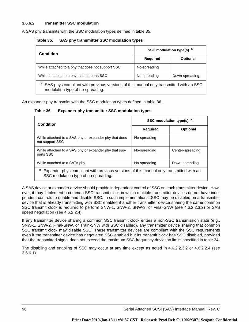
96 Serial Attached SCSI (SAS) Interface Manual, Rev. C
3.6.6.2 Transmitter SSC modulation
A SAS phy transmits with the SSC modulation types defined in table 35.
An expander phy transmits with the SSC modulation types defined in table 36.
A SAS device or expander device should provide independent control of SSC on each transmitter device. How-ever, it may implement a common SSC transmit clock in which multiple transmitter devices do not have inde-pendent controls to enable and disable SSC. In such implementations, SSC may be disabled on a transmitter device that is already transmitting with SSC enabled if another transmitter device sharing the same common SSC transmit clock is required to perform SNW-1, SNW-2, SNW-3, or Final-SNW (see 4.6.2.2.3.2) or SAS speed negotiation (see 4.6.2.2.4).
If any transmitter device sharing a common SSC transmit clock enters a non-SSC transmission state (e.g., SNW-1, SNW-2, Final-SNW, or Train-SNW with SSC disabled), any transmitter device sharing that common SSC transmit clock may disable SSC. These transmitter devices are compliant with the SSC requirements even if the transmitter device has negotiated SSC enabled but its transmit clock has SSC disabled, provided that the transmitted signal does not exceed the maximum SSC frequency deviation limits specified in table 34.
The disabling and enabling of SSC may occur at any time except as noted in 4.6.2.2.3.2 or 4.6.2.2.4 (see 3.6.6.1).
Table 35. SAS phy transmitter SSC modulation types
ConditionSSC modulation type(s) a
Required Optional
While attached to a phy that does not support SSC No-spreading
While attached to a phy that supports SSC No-spreading Down-spreading
a SAS phys compliant with previous versions of this manual only transmitted with an SSC modulation type of no-spreading.
Table 36. Expander phy transmitter SSC modulation types
ConditionSSC modulation type(s) a
Required Optional
While attached to a SAS phy or expander phy that does not support SSC
No-spreading
While attached to a SAS phy or expander phy that sup-ports SSC
No-spreading Center-spreading
While attached to a SATA phy No-spreading Down-spreading
a Expander phys compliant with previous versions of this manual only transmitted with an SSC modulation type of no-spreading.
Print Date:2010-Jan-13 11:56:37 CST Released; Prod Rel; C; 100293071 Seagate Confidential
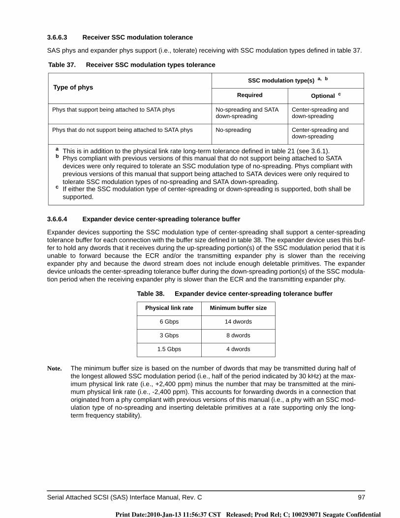
Serial Attached SCSI (SAS) Interface Manual, Rev. C 97
3.6.6.3 Receiver SSC modulation tolerance
SAS phys and expander phys support (i.e., tolerate) receiving with SSC modulation types defined in table 37.
3.6.6.4 Expander device center-spreading tolerance buffer
Expander devices supporting the SSC modulation type of center-spreading shall support a center-spreading tolerance buffer for each connection with the buffer size defined in table 38. The expander device uses this buf-fer to hold any dwords that it receives during the up-spreading portion(s) of the SSC modulation period that it is unable to forward because the ECR and/or the transmitting expander phy is slower than the receiving expander phy and because the dword stream does not include enough deletable primitives. The expander device unloads the center-spreading tolerance buffer during the down-spreading portion(s) of the SSC modula-tion period when the receiving expander phy is slower than the ECR and the transmitting expander phy.
Note. The minimum buffer size is based on the number of dwords that may be transmitted during half of the longest allowed SSC modulation period (i.e., half of the period indicated by 30 kHz) at the max-imum physical link rate (i.e., +2,400 ppm) minus the number that may be transmitted at the mini-mum physical link rate (i.e., -2,400 ppm). This accounts for forwarding dwords in a connection that originated from a phy compliant with previous versions of this manual (i.e., a phy with an SSC mod-ulation type of no-spreading and inserting deletable primitives at a rate supporting only the long-term frequency stability).
Table 37. Receiver SSC modulation types tolerance
Type of physSSC modulation type(s) a, b
Required Optional c
Phys that support being attached to SATA phys No-spreading and SATA down-spreading
Center-spreading and down-spreading
Phys that do not support being attached to SATA phys No-spreading Center-spreading and down-spreading
a This is in addition to the physical link rate long-term tolerance defined in table 21 (see 3.6.1).b Phys compliant with previous versions of this manual that do not support being attached to SATA
devices were only required to tolerate an SSC modulation type of no-spreading. Phys compliant with previous versions of this manual that support being attached to SATA devices were only required to tolerate SSC modulation types of no-spreading and SATA down-spreading.
c If either the SSC modulation type of center-spreading or down-spreading is supported, both shall be supported.
Table 38. Expander device center-spreading tolerance buffer
Physical link rate Minimum buffer size
6 Gbps 14 dwords
3 Gbps 8 dwords
1.5 Gbps 4 dwords
Print Date:2010-Jan-13 11:56:37 CST Released; Prod Rel; C; 100293071 Seagate Confidential
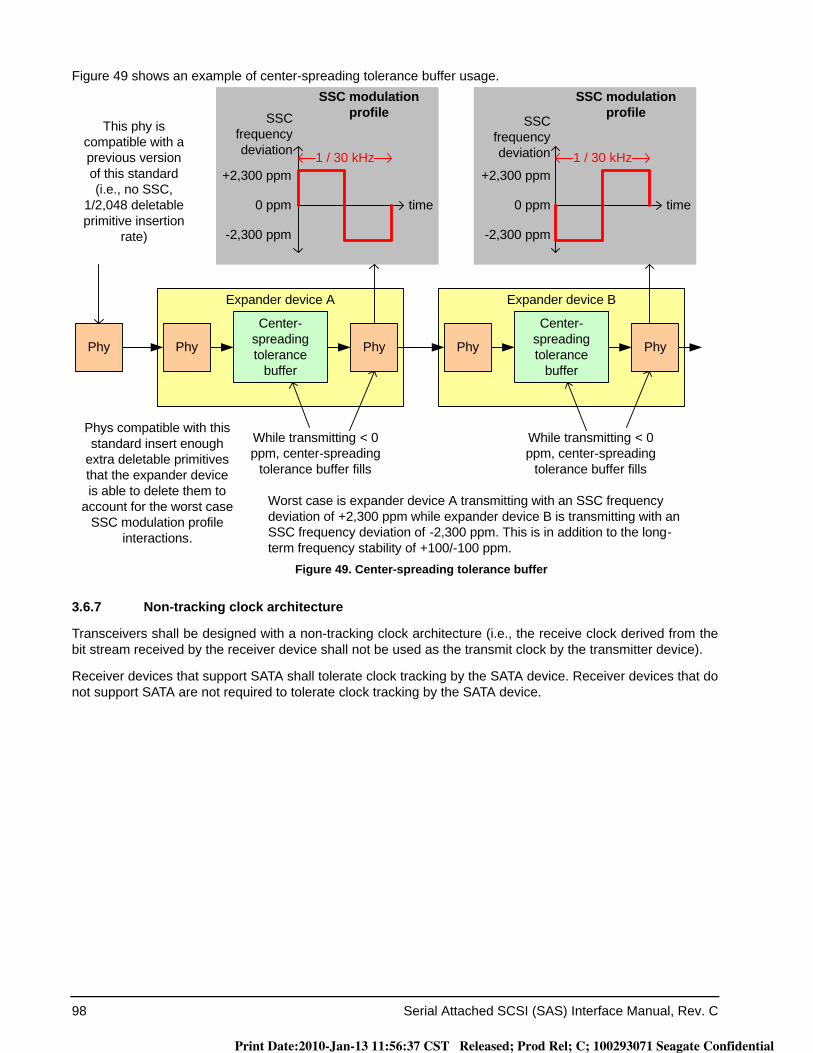
98 Serial Attached SCSI (SAS) Interface Manual, Rev. C
Figure 49 shows an example of center-spreading tolerance buffer usage.
Figure 49. Center-spreading tolerance buffer
3.6.7 Non-tracking clock architecture
Transceivers shall be designed with a non-tracking clock architecture (i.e., the receive clock derived from the bit stream received by the receiver device shall not be used as the transmit clock by the transmitter device).
Receiver devices that support SATA shall tolerate clock tracking by the SATA device. Receiver devices that do not support SATA are not required to tolerate clock tracking by the SATA device.
Phy Phy
Center-spreading tolerance
buffer
+2,300 ppm
-2,300 ppm
0 ppm
+2,300 ppm
-2,300 ppm
0 ppm
SSC modulation profile
SSC modulation profile
Expander device B
1 / 30 kHz 1 / 30 kHz
SSC frequency deviation
timetime
SSC frequency deviation
Phy Phy
Center-spreading tolerance
buffer
Expander device A
Phy
This phy is compatible with a previous version of this standard (i.e., no SSC,
1/2,048 deletable primitive insertion
rate)
While transmitting < 0 ppm, center-spreading
tolerance buffer fills
While transmitting < 0 ppm, center-spreading
tolerance buffer fills
Worst case is expander device A transmitting with an SSC frequency deviation of +2,300 ppm while expander device B is transmitting with an SSC frequency deviation of -2,300 ppm. This is in addition to the long-term frequency stability of +100/-100 ppm.
Phys compatible with this standard insert enough
extra deletable primitives that the expander device is able to delete them to
account for the worst case SSC modulation profile
interactions.
Print Date:2010-Jan-13 11:56:37 CST Released; Prod Rel; C; 100293071 Seagate Confidential
Serial Attached SCSI (SAS) Interface Manual, Rev. C (Draft 5) 99
4.0 Phy layer
4.1 Phy layer overview
The phy layer defines 8b10b coding and OOB signals. Phy layer interfaces between the link layer and the physical layer to perform the phy reset sequence and keep track of dword synchronization.
4.2 Encoding (8b10b)
4.2.1 8b10b Encoding overview
All data bytes transferred in SAS are encoded into 10-bit data characters using 8b10b coding. Additional char-acters not related to data bytes are called control characters.
Out of all 1024 possible 10-bit characters:a) some of the characters are data characters, representing the 256 possible 8-bit data bytes;b) some of the characters are control characters, used for primitives (e.g., frame delimiters) and other
control purposes; andc) the rest of the characters are invalid characters.
8b10b coding ensures that sufficient transitions are present in the serial bit stream to make clock recovery pos-sible at the receiver. 8b10b coding also increases the likelihood of detecting any single or multiple bit errors that occur during transmission and reception. In addition, some of the control characters of the transmission code contain a distinct bit pattern, called a comma pattern, which assists a receiver in achieving character and dword alignment on the incoming bit stream.
4.2.2 8b10b coding notation conventions
This subclause uses letter notation for describing information bits and control variables. Such notation differs from the bit notation specified by the remainder of this manual. The following text describes the translation pro-cess between these notations and provides a translation example. This subclause also describes the conven-tions used to name valid characters. This text is provided for the purposes of terminology clarification only.
An unencoded information byte is composed of:a) eight information bits labeled A, B, C, D, E, F, G, and H. Each information bit contains either a binary
zero or a binary one; andb) a control variable labeled Z. A control variable has either the value D or the value K:
A) D means the information byte is a data byte; and B) K means the information byte is a control byte.
Print Date:2010-Jan-13 11:56:37 CST Released; Prod Rel; C; 100293071 Seagate Confidential
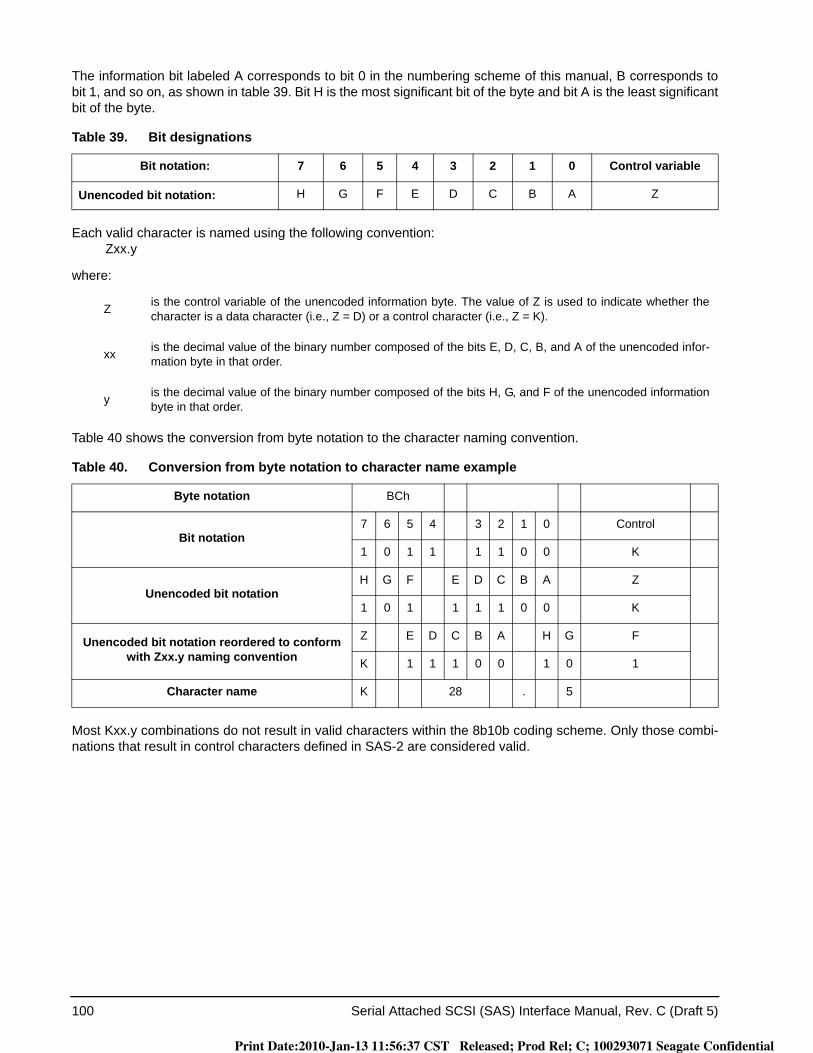
100 Serial Attached SCSI (SAS) Interface Manual, Rev. C (Draft 5)
The information bit labeled A corresponds to bit 0 in the numbering scheme of this manual, B corresponds to bit 1, and so on, as shown in table 39. Bit H is the most significant bit of the byte and bit A is the least significant bit of the byte.
Each valid character is named using the following convention:Zxx.y
where:
Table 40 shows the conversion from byte notation to the character naming convention.
Most Kxx.y combinations do not result in valid characters within the 8b10b coding scheme. Only those combi-nations that result in control characters defined in SAS-2 are considered valid.
Table 39. Bit designations
Bit notation: 7 6 5 4 3 2 1 0 Control variable
Unencoded bit notation: H G F E D C B A Z
Z is the control variable of the unencoded information byte. The value of Z is used to indicate whether the character is a data character (i.e., Z = D) or a control character (i.e., Z = K).
xx is the decimal value of the binary number composed of the bits E, D, C, B, and A of the unencoded infor-mation byte in that order.
y is the decimal value of the binary number composed of the bits H, G, and F of the unencoded information byte in that order.
Table 40. Conversion from byte notation to character name example
Byte notation BCh
Bit notation7 6 5 4 3 2 1 0 Control
1 0 1 1 1 1 0 0 K
Unencoded bit notationH G F E D C B A Z
1 0 1 1 1 1 0 0 K
Unencoded bit notation reordered to conform with Zxx.y naming convention
Z E D C B A H G F
K 1 1 1 0 0 1 0 1
Character name K 28 . 5
Print Date:2010-Jan-13 11:56:37 CST Released; Prod Rel; C; 100293071 Seagate Confidential
Serial Attached SCSI (SAS) Interface Manual, Rev. C (Draft 5) 101
4.3 Character encoding and decoding
4.3.1 Introduction
This subclause describes how to select valid characters (i.e., 8b10b encoding) and check the validity of received characters (i.e., 10b8b decoding), and specifies the ordering rules to be followed when transmitting the bits within a character.
4.3.2 Bit transmission order
An information byte is encoded into a 10-bit character containing bits labeled a, b, c, d, e, i, f, g, h, and j. Bit a shall be transmitted first, followed by bits b, c, d, e, i, f, g, h, and j, in that order.
Note. Bit i is transmitted between bit e and bit f, rather than in the order indicated by the letters of the alphabet.
4.3.3 Character transmission order
Characters within primitives shall be transmitted sequentially beginning with the control character used to dis-tinguish the primitive (e.g., K28.3 or K28.5) and proceeding character by character from left to right within the definition of the primitive until all characters of the primitive are transmitted.
4.3.4 Frame transmission order
The contents of a frame shall be transmitted sequentially beginning with the primitive used to denote the start of frame (e.g., SOAF, SOF, or SATA_SOF) and proceeding character-by-character from left to right within the definition of the frame until the primitive used to denote the end of frame (e.g., EOAF, EOF, or SATA_EOF) is transmitted.
4.3.5 Running disparity (RD)
RD is a binary parameter with a negative (-) or positive (+) value. After power on, the transmitter may initialize the current RD to either positive or negative.
Each data character and control character is defined in a table by two columns that represent two, not neces-sarily different, characters, corresponding to the current value of the running disparity (i.e., current RD - or cur-rent RD +).
Upon transmission of any character, the transmitter shall calculate a new value for its RD based on the con-tents of the transmitted character.
After power on, the receiver shall assume either the positive or negative value for its initial RD. Upon reception of any character, the receiver shall determine whether the character is valid or invalid and shall calculate a new value for its RD based on the contents of the received character.
The following rules for RD shall be used to calculate the new RD value for characters that have been transmit-ted (i.e., the transmitter’s RD) and that have been received (i.e., the receiver’s RD).
RD for a character shall be calculated on the basis of sub-blocks, where the first six bits (i.e., bits a, b, c, d, e, and i) form one sub-block (i.e., the six-bit sub-block) and the second four bits (i.e., bits f, g, h, and j) form the other sub-block (i.e., the four-bit sub-block). RD has the following properties:
a) RD at the beginning of the six-bit sub-block is the RD at the end of the preceding character;b) RD at the beginning of the four-bit sub-block is the RD at the end of the preceding six-bit sub-block;
andc) RD at the end of the character is the RD at the end of the four-bit sub-block.
Print Date:2010-Jan-13 11:56:37 CST Released; Prod Rel; C; 100293071 Seagate Confidential

102 Serial Attached SCSI (SAS) Interface Manual, Rev. C (Draft 5)
RD for the sub-blocks shall be calculated as follows:a) if the sub-block contains more ones than zeros, then RD at the end of a sub-block is positive;b) if the sub-block contains more zeros than ones, then RD at the end of a sub-block is negative; orc) if the sub-block contains equal numbers of zeros and ones, then:
A) if it is a six-bit sub-block containing 000111b, then RD at the end of the sub-block is positive;B) if it is a six-bit sub-block containing 111000b, then RD at the end of the sub-block is negative;C) if it is a four-bit sub-block containing 0011b, then RD at the end of the sub-block is positive;D) if it is a four-bit sub-block containing 1100b, then RD at the end of the sub-block is negative; orE) otherwise, RD at the end of the sub-block is the same as at the beginning of the sub-block.
All sub-blocks with equal numbers of zeros and ones have neutral disparity (i.e., the ending disparity is the same as the beginning disparity). In order to limit the run length of zeros or ones across adjacent sub-blocks, the 8b10b code rules specify that sub-blocks encoded as 000111b or 0011b are generated only when the RD at the beginning of the sub-block is positive, ensuring that RD at the end of these sub-blocks is also positive. Likewise, sub-blocks containing 111000b or 1100b are generated only when the RD at the beginning of the sub-block is negative, ensuring that RD at the end of these sub-blocks is also negative.
Running disparity (RD) shall be maintained separately on each physical link in each direction. During a con-nection (see 2.1.11), expander devices shall convert incoming 10-bit characters to 8-bit bytes and generate the 10-bit character with correct disparity for the output physical link. Phys within a device may or may not begin operation with the same disparity.
4.3.6 Data characters
Table 41 defines the data characters (i.e., Dxx.y characters), and shall be used for both generating characters (i.e., encoding) and checking the validity of received characters (i.e., decoding)..
Table 41. Data characters
Name
Data byte Data character(binary representation)
Binary representation(HGF EDCBA)
Hexadecimal representation
Current RD -abcdei fghj
Current RD +abcdei fghj
D00.0 000 00000 00h 100111 0100 011000 1011
D01.0 000 00001 01h 011101 0100 100010 1011
D02.0 000 00010 02h 101101 0100 010010 1011
D03.0 000 00011 03h 110001 1011 110001 0100
D04.0 000 00100 04h 110101 0100 001010 1011
D05.0 000 00101 05h 101001 1011 101001 0100
D06.0 000 00110 06h 011001 1011 011001 0100
D07.0 000 00111 07h 111000 1011 000111 0100
D08.0 000 01000 08h 111001 0100 000110 1011
D09.0 000 01001 09h 100101 1011 100101 0100
D10.0 000 01010 0Ah 010101 1011 010101 0100
D11.0 000 01011 0Bh 110100 1011 110100 0100
D12.0 000 01100 0Ch 001101 1011 001101 0100
D13.0 000 01101 0Dh 101100 1011 101100 0100
D14.0 000 01110 0Eh 011100 1011 011100 0100
D15.0 000 01111 0Fh 010111 0100 101000 1011
D16.0 000 10000 10h 011011 0100 100100 1011
D17.0 000 10001 11h 100011 1011 100011 0100
Print Date:2010-Jan-13 11:56:37 CST Released; Prod Rel; C; 100293071 Seagate Confidential
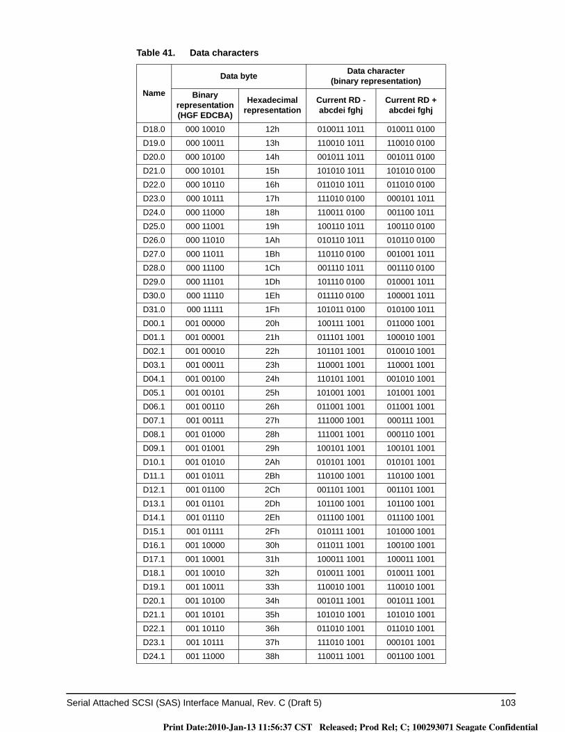
Serial Attached SCSI (SAS) Interface Manual, Rev. C (Draft 5) 103
D18.0 000 10010 12h 010011 1011 010011 0100
D19.0 000 10011 13h 110010 1011 110010 0100
D20.0 000 10100 14h 001011 1011 001011 0100
D21.0 000 10101 15h 101010 1011 101010 0100
D22.0 000 10110 16h 011010 1011 011010 0100
D23.0 000 10111 17h 111010 0100 000101 1011
D24.0 000 11000 18h 110011 0100 001100 1011
D25.0 000 11001 19h 100110 1011 100110 0100
D26.0 000 11010 1Ah 010110 1011 010110 0100
D27.0 000 11011 1Bh 110110 0100 001001 1011
D28.0 000 11100 1Ch 001110 1011 001110 0100
D29.0 000 11101 1Dh 101110 0100 010001 1011
D30.0 000 11110 1Eh 011110 0100 100001 1011
D31.0 000 11111 1Fh 101011 0100 010100 1011
D00.1 001 00000 20h 100111 1001 011000 1001
D01.1 001 00001 21h 011101 1001 100010 1001
D02.1 001 00010 22h 101101 1001 010010 1001
D03.1 001 00011 23h 110001 1001 110001 1001
D04.1 001 00100 24h 110101 1001 001010 1001
D05.1 001 00101 25h 101001 1001 101001 1001
D06.1 001 00110 26h 011001 1001 011001 1001
D07.1 001 00111 27h 111000 1001 000111 1001
D08.1 001 01000 28h 111001 1001 000110 1001
D09.1 001 01001 29h 100101 1001 100101 1001
D10.1 001 01010 2Ah 010101 1001 010101 1001
D11.1 001 01011 2Bh 110100 1001 110100 1001
D12.1 001 01100 2Ch 001101 1001 001101 1001
D13.1 001 01101 2Dh 101100 1001 101100 1001
D14.1 001 01110 2Eh 011100 1001 011100 1001
D15.1 001 01111 2Fh 010111 1001 101000 1001
D16.1 001 10000 30h 011011 1001 100100 1001
D17.1 001 10001 31h 100011 1001 100011 1001
D18.1 001 10010 32h 010011 1001 010011 1001
D19.1 001 10011 33h 110010 1001 110010 1001
D20.1 001 10100 34h 001011 1001 001011 1001
D21.1 001 10101 35h 101010 1001 101010 1001
D22.1 001 10110 36h 011010 1001 011010 1001
D23.1 001 10111 37h 111010 1001 000101 1001
D24.1 001 11000 38h 110011 1001 001100 1001
Table 41. Data characters
Name
Data byte Data character(binary representation)
Binary representation(HGF EDCBA)
Hexadecimal representation
Current RD -abcdei fghj
Current RD +abcdei fghj
Print Date:2010-Jan-13 11:56:37 CST Released; Prod Rel; C; 100293071 Seagate Confidential

104 Serial Attached SCSI (SAS) Interface Manual, Rev. C (Draft 5)
D25.1 001 11001 39h 100110 1001 100110 1001
D26.1 001 11010 3Ah 010110 1001 010110 1001
D27.1 001 11011 3Bh 110110 1001 001001 1001
D28.1 001 11100 3Ch 001110 1001 001110 1001
D29.1 001 11101 3Dh 101110 1001 010001 1001
D30.1 001 11110 3Eh 011110 1001 100001 1001
D31.1 001 11111 3Fh 101011 1001 010100 1001
D00.2 010 00000 40h 100111 0101 011000 0101
D01.2 010 00001 41h 011101 0101 100010 0101
D02.2 010 00010 42h 101101 0101 010010 0101
D03.2 010 00011 43h 110001 0101 110001 0101
D04.2 010 00100 44h 110101 0101 001010 0101
D05.2 010 00101 45h 101001 0101 101001 0101
D06.2 010 00110 46h 011001 0101 011001 0101
D07.2 010 00111 47h 111000 0101 000111 0101
D08.2 010 01000 48h 111001 0101 000110 0101
D09.2 010 01001 49h 100101 0101 100101 0101
D10.2 010 01010 4Ah 010101 0101 010101 0101
D11.2 010 01011 4Bh 110100 0101 110100 0101
D12.2 010 01100 4Ch 001101 0101 001101 0101
D13.2 010 01101 4Dh 101100 0101 101100 0101
D14.2 010 01110 4Eh 011100 0101 011100 0101
D15.2 010 01111 4Fh 010111 0101 101000 0101
D16.2 010 10000 50h 011011 0101 100100 0101
D17.2 010 10001 51h 100011 0101 100011 0101
D18.2 010 10010 52h 010011 0101 010011 0101
D19.2 010 10011 53h 110010 0101 110010 0101
D20.2 010 10100 54h 001011 0101 001011 0101
D21.2 010 10101 55h 101010 0101 101010 0101
D22.2 010 10110 56h 011010 0101 011010 0101
D23.2 010 10111 57h 111010 0101 000101 0101
D24.2 010 11000 58h 110011 0101 001100 0101
D25.2 010 11001 59h 100110 0101 100110 0101
D26.2 010 11010 5Ah 010110 0101 010110 0101
D27.2 010 11011 5Bh 110110 0101 001001 0101
D28.2 010 11100 5Ch 001110 0101 001110 0101
D29.2 010 11101 5Dh 101110 0101 010001 0101
D30.2 010 11110 5Eh 011110 0101 100001 0101
D31.2 010 11111 5Fh 101011 0101 010100 0101
Table 41. Data characters
Name
Data byte Data character(binary representation)
Binary representation(HGF EDCBA)
Hexadecimal representation
Current RD -abcdei fghj
Current RD +abcdei fghj
Print Date:2010-Jan-13 11:56:37 CST Released; Prod Rel; C; 100293071 Seagate Confidential
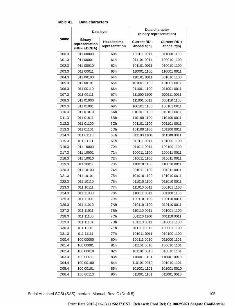
Serial Attached SCSI (SAS) Interface Manual, Rev. C (Draft 5) 105
D00.3 011 00000 60h 100111 0011 011000 1100
D01.3 011 00001 61h 011101 0011 100010 1100
D02.3 011 00010 62h 101101 0011 010010 1100
D03.3 011 00011 63h 110001 1100 110001 0011
D04.3 011 00100 64h 110101 0011 001010 1100
D05.3 011 00101 65h 101001 1100 101001 0011
D06.3 011 00110 66h 011001 1100 011001 0011
D07.3 011 00111 67h 111000 1100 000111 0011
D08.3 011 01000 68h 111001 0011 000110 1100
D09.3 011 01001 69h 100101 1100 100101 0011
D10.3 011 01010 6Ah 010101 1100 010101 0011
D11.3 011 01011 6Bh 110100 1100 110100 0011
D12.3 011 01100 6Ch 001101 1100 001101 0011
D13.3 011 01101 6Dh 101100 1100 101100 0011
D14.3 011 01110 6Eh 011100 1100 011100 0011
D15.3 011 01111 6Fh 010111 0011 101000 1100
D16.3 011 10000 70h 011011 0011 100100 1100
D17.3 011 10001 71h 100011 1100 100011 0011
D18.3 011 10010 72h 010011 1100 010011 0011
D19.3 011 10011 73h 110010 1100 110010 0011
D20.3 011 10100 74h 001011 1100 001011 0011
D21.3 011 10101 75h 101010 1100 101010 0011
D22.3 011 10110 76h 011010 1100 011010 0011
D23.3 011 10111 77h 111010 0011 000101 1100
D24.3 011 11000 78h 110011 0011 001100 1100
D25.3 011 11001 79h 100110 1100 100110 0011
D26.3 011 11010 7Ah 010110 1100 010110 0011
D27.3 011 11011 7Bh 110110 0011 001001 1100
D28.3 011 11100 7Ch 001110 1100 001110 0011
D29.3 011 11101 7Dh 101110 0011 010001 1100
D30.3 011 11110 7Eh 011110 0011 100001 1100
D31.3 011 11111 7Fh 101011 0011 010100 1100
D00.4 100 00000 80h 100111 0010 011000 1101
D01.4 100 00001 81h 011101 0010 100010 1101
D02.4 100 00010 82h 101101 0010 010010 1101
D03.4 100 00011 83h 110001 1101 110001 0010
D04.4 100 00100 84h 110101 0010 001010 1101
D05.4 100 00101 85h 101001 1101 101001 0010
D06.4 100 00110 86h 011001 1101 011001 0010
Table 41. Data characters
Name
Data byte Data character(binary representation)
Binary representation(HGF EDCBA)
Hexadecimal representation
Current RD -abcdei fghj
Current RD +abcdei fghj
Print Date:2010-Jan-13 11:56:37 CST Released; Prod Rel; C; 100293071 Seagate Confidential

106 Serial Attached SCSI (SAS) Interface Manual, Rev. C (Draft 5)
D07.4 100 00111 87h 111000 1101 000111 0010
D08.4 100 01000 88h 111001 0010 000110 1101
D09.4 100 01001 89h 100101 1101 100101 0010
D10.4 100 01010 8Ah 010101 1101 010101 0010
D11.4 100 01011 8Bh 110100 1101 110100 0010
D12.4 100 01100 8Ch 001101 1101 001101 0010
D13.4 100 01101 8Dh 101100 1101 101100 0010
D14.4 100 01110 8Eh 011100 1101 011100 0010
D15.4 100 01111 8Fh 010111 0010 101000 1101
D16.4 100 10000 90h 011011 0010 100100 1101
D17.4 100 10001 91h 100011 1101 100011 0010
D18.4 100 10010 92h 010011 1101 010011 0010
D19.4 100 10011 93h 110010 1101 110010 0010
D20.4 100 10100 94h 001011 1101 001011 0010
D21.4 100 10101 95h 101010 1101 101010 0010
D22.4 100 10110 96h 011010 1101 011010 0010
D23.4 100 10111 97h 111010 0010 000101 1101
D24.4 100 11000 98h 110011 0010 001100 1101
D25.4 100 11001 99h 100110 1101 100110 0010
D26.4 100 11010 9Ah 010110 1101 010110 0010
D27.4 100 11011 9Bh 110110 0010 001001 1101
D28.4 100 11100 9Ch 001110 1101 001110 0010
D29.4 100 11101 9Dh 101110 0010 010001 1101
D30.4 100 11110 9Eh 011110 0010 100001 1101
D31.4 100 11111 9Fh 101011 0010 010100 1101
D00.5 101 00000 A0h 100111 1010 011000 1010
D01.5 101 00001 A1h 011101 1010 100010 1010
D02.5 101 00010 A2h 101101 1010 010010 1010
D03.5 101 00011 A3h 110001 1010 110001 1010
D04.5 101 00100 A4h 110101 1010 001010 1010
D05.5 101 00101 A5h 101001 1010 101001 1010
D06.5 101 00110 A6h 011001 1010 011001 1010
D07.5 101 00111 A7h 111000 1010 000111 1010
D08.5 101 01000 A8h 111001 1010 000110 1010
D09.5 101 01001 A9h 100101 1010 100101 1010
D10.5 101 01010 AAh 010101 1010 010101 1010
D11.5 101 01011 ABh 110100 1010 110100 1010
D12.5 101 01100 ACh 001101 1010 001101 1010
D13.5 101 01101 ADh 101100 1010 101100 1010
Table 41. Data characters
Name
Data byte Data character(binary representation)
Binary representation(HGF EDCBA)
Hexadecimal representation
Current RD -abcdei fghj
Current RD +abcdei fghj
Print Date:2010-Jan-13 11:56:37 CST Released; Prod Rel; C; 100293071 Seagate Confidential
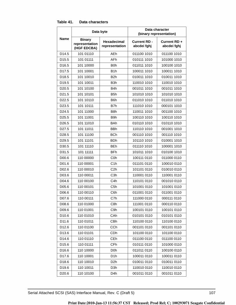
Serial Attached SCSI (SAS) Interface Manual, Rev. C (Draft 5) 107
D14.5 101 01110 AEh 011100 1010 011100 1010
D15.5 101 01111 AFh 010111 1010 101000 1010
D16.5 101 10000 B0h 011011 1010 100100 1010
D17.5 101 10001 B1h 100011 1010 100011 1010
D18.5 101 10010 B2h 010011 1010 010011 1010
D19.5 101 10011 B3h 110010 1010 110010 1010
D20.5 101 10100 B4h 001011 1010 001011 1010
D21.5 101 10101 B5h 101010 1010 101010 1010
D22.5 101 10110 B6h 011010 1010 011010 1010
D23.5 101 10111 B7h 111010 1010 000101 1010
D24.5 101 11000 B8h 110011 1010 001100 1010
D25.5 101 11001 B9h 100110 1010 100110 1010
D26.5 101 11010 BAh 010110 1010 010110 1010
D27.5 101 11011 BBh 110110 1010 001001 1010
D28.5 101 11100 BCh 001110 1010 001110 1010
D29.5 101 11101 BDh 101110 1010 010001 1010
D30.5 101 11110 BEh 011110 1010 100001 1010
D31.5 101 11111 BFh 101011 1010 010100 1010
D00.6 110 00000 C0h 100111 0110 011000 0110
D01.6 110 00001 C1h 011101 0110 100010 0110
D02.6 110 00010 C2h 101101 0110 010010 0110
D03.6 110 00011 C3h 110001 0110 110001 0110
D04.6 110 00100 C4h 110101 0110 001010 0110
D05.6 110 00101 C5h 101001 0110 101001 0110
D06.6 110 00110 C6h 011001 0110 011001 0110
D07.6 110 00111 C7h 111000 0110 000111 0110
D08.6 110 01000 C8h 111001 0110 000110 0110
D09.6 110 01001 C9h 100101 0110 100101 0110
D10.6 110 01010 CAh 010101 0110 010101 0110
D11.6 110 01011 CBh 110100 0110 110100 0110
D12.6 110 01100 CCh 001101 0110 001101 0110
D13.6 110 01101 CDh 101100 0110 101100 0110
D14.6 110 01110 CEh 011100 0110 011100 0110
D15.6 110 01111 CFh 010111 0110 101000 0110
D16.6 110 10000 D0h 011011 0110 100100 0110
D17.6 110 10001 D1h 100011 0110 100011 0110
D18.6 110 10010 D2h 010011 0110 010011 0110
D19.6 110 10011 D3h 110010 0110 110010 0110
D20.6 110 10100 D4h 001011 0110 001011 0110
Table 41. Data characters
Name
Data byte Data character(binary representation)
Binary representation(HGF EDCBA)
Hexadecimal representation
Current RD -abcdei fghj
Current RD +abcdei fghj
Print Date:2010-Jan-13 11:56:37 CST Released; Prod Rel; C; 100293071 Seagate Confidential

108 Serial Attached SCSI (SAS) Interface Manual, Rev. C (Draft 5)
D21.6 110 10101 D5h 101010 0110 101010 0110
D22.6 110 10110 D6h 011010 0110 011010 0110
D23.6 110 10111 D7h 111010 0110 000101 0110
D24.6 110 11000 D8h 110011 0110 001100 0110
D25.6 110 11001 D9h 100110 0110 100110 0110
D26.6 110 11010 DAh 010110 0110 010110 0110
D27.6 110 11011 DBh 110110 0110 001001 0110
D28.6 110 11100 DCh 001110 0110 001110 0110
D29.6 110 11101 DDh 101110 0110 010001 0110
D30.6 110 11110 DEh 011110 0110 100001 0110
D31.6 110 11111 DFh 101011 0110 010100 0110
D00.7 111 00000 E0h 100111 0001 011000 1110
D01.7 111 00001 E1h 011101 0001 100010 1110
D02.7 111 00010 E2h 101101 0001 010010 1110
D03.7 111 00011 E3h 110001 1110 110001 0001
D04.7 111 00100 E4h 110101 0001 001010 1110
D05.7 111 00101 E5h 101001 1110 101001 0001
D06.7 111 00110 E6h 011001 1110 011001 0001
D07.7 111 00111 E7h 111000 1110 000111 0001
D08.7 111 01000 E8h 111001 0001 000110 1110
D09.7 111 01001 E9h 100101 1110 100101 0001
D10.7 111 01010 EAh 010101 1110 010101 0001
D11.7 111 01011 EBh 110100 1110 110100 1000
D12.7 111 01100 ECh 001101 1110 001101 0001
D13.7 111 01101 EDh 101100 1110 101100 1000
D14.7 111 01110 EEh 011100 1110 011100 1000
D15.7 111 01111 EFh 010111 0001 101000 1110
Table 41. Data characters
Name
Data byte Data character(binary representation)
Binary representation(HGF EDCBA)
Hexadecimal representation
Current RD -abcdei fghj
Current RD +abcdei fghj
Print Date:2010-Jan-13 11:56:37 CST Released; Prod Rel; C; 100293071 Seagate Confidential
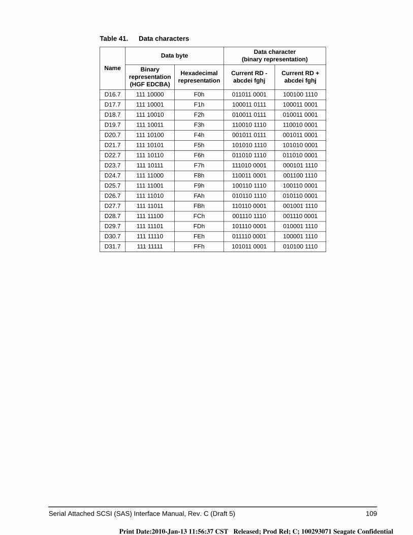
Serial Attached SCSI (SAS) Interface Manual, Rev. C (Draft 5) 109
D16.7 111 10000 F0h 011011 0001 100100 1110
D17.7 111 10001 F1h 100011 0111 100011 0001
D18.7 111 10010 F2h 010011 0111 010011 0001
D19.7 111 10011 F3h 110010 1110 110010 0001
D20.7 111 10100 F4h 001011 0111 001011 0001
D21.7 111 10101 F5h 101010 1110 101010 0001
D22.7 111 10110 F6h 011010 1110 011010 0001
D23.7 111 10111 F7h 111010 0001 000101 1110
D24.7 111 11000 F8h 110011 0001 001100 1110
D25.7 111 11001 F9h 100110 1110 100110 0001
D26.7 111 11010 FAh 010110 1110 010110 0001
D27.7 111 11011 FBh 110110 0001 001001 1110
D28.7 111 11100 FCh 001110 1110 001110 0001
D29.7 111 11101 FDh 101110 0001 010001 1110
D30.7 111 11110 FEh 011110 0001 100001 1110
D31.7 111 11111 FFh 101011 0001 010100 1110
Table 41. Data characters
Name
Data byte Data character(binary representation)
Binary representation(HGF EDCBA)
Hexadecimal representation
Current RD -abcdei fghj
Current RD +abcdei fghj
Print Date:2010-Jan-13 11:56:37 CST Released; Prod Rel; C; 100293071 Seagate Confidential
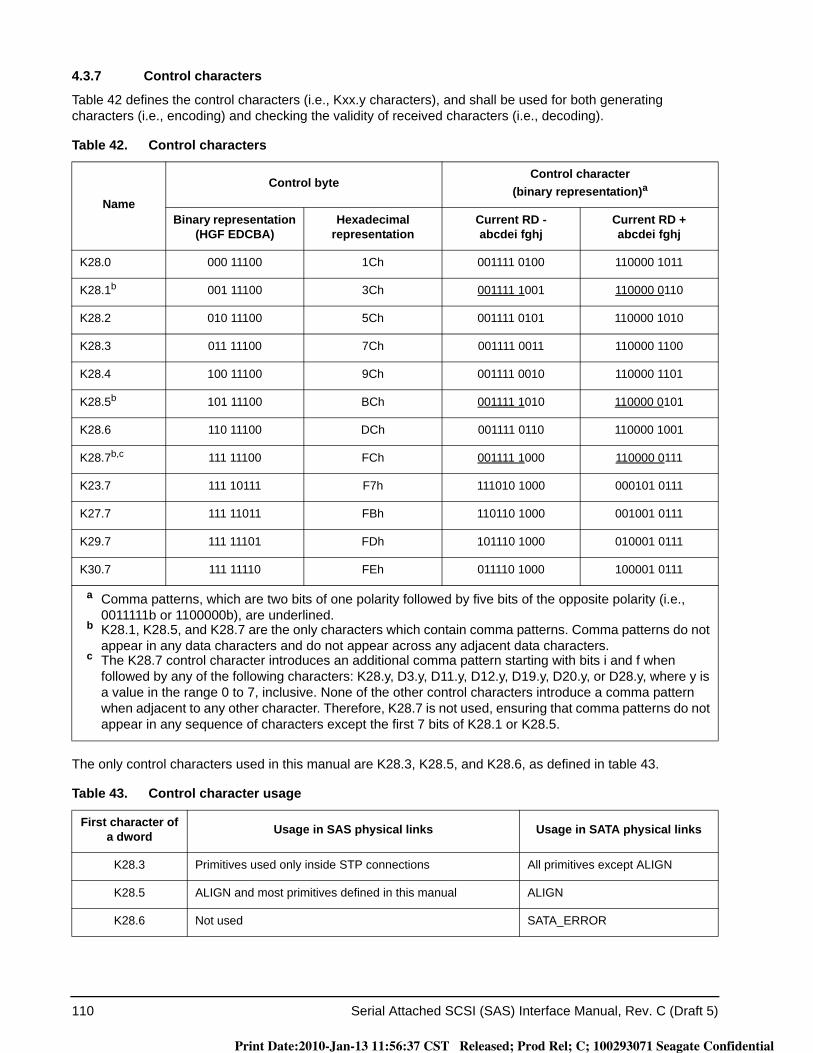
110 Serial Attached SCSI (SAS) Interface Manual, Rev. C (Draft 5)
4.3.7 Control characters
Table 42 defines the control characters (i.e., Kxx.y characters), and shall be used for both generating characters (i.e., encoding) and checking the validity of received characters (i.e., decoding).
The only control characters used in this manual are K28.3, K28.5, and K28.6, as defined in table 43.
Table 42. Control characters
Name
Control byteControl character
(binary representation)a
Binary representation (HGF EDCBA)
Hexadecimal representation
Current RD -abcdei fghj
Current RD +abcdei fghj
K28.0 000 11100 1Ch 001111 0100 110000 1011
K28.1b 001 11100 3Ch 001111 1001 110000 0110
K28.2 010 11100 5Ch 001111 0101 110000 1010
K28.3 011 11100 7Ch 001111 0011 110000 1100
K28.4 100 11100 9Ch 001111 0010 110000 1101
K28.5b 101 11100 BCh 001111 1010 110000 0101
K28.6 110 11100 DCh 001111 0110 110000 1001
K28.7b,c 111 11100 FCh 001111 1000 110000 0111
K23.7 111 10111 F7h 111010 1000 000101 0111
K27.7 111 11011 FBh 110110 1000 001001 0111
K29.7 111 11101 FDh 101110 1000 010001 0111
K30.7 111 11110 FEh 011110 1000 100001 0111
a Comma patterns, which are two bits of one polarity followed by five bits of the opposite polarity (i.e., 0011111b or 1100000b), are underlined.
b K28.1, K28.5, and K28.7 are the only characters which contain comma patterns. Comma patterns do not appear in any data characters and do not appear across any adjacent data characters.
c The K28.7 control character introduces an additional comma pattern starting with bits i and f when followed by any of the following characters: K28.y, D3.y, D11.y, D12.y, D19.y, D20.y, or D28.y, where y is a value in the range 0 to 7, inclusive. None of the other control characters introduce a comma pattern when adjacent to any other character. Therefore, K28.7 is not used, ensuring that comma patterns do not appear in any sequence of characters except the first 7 bits of K28.1 or K28.5.
Table 43. Control character usage
First character of a dword Usage in SAS physical links Usage in SATA physical links
K28.3 Primitives used only inside STP connections All primitives except ALIGN
K28.5 ALIGN and most primitives defined in this manual ALIGN
K28.6 Not used SATA_ERROR
Print Date:2010-Jan-13 11:56:37 CST Released; Prod Rel; C; 100293071 Seagate Confidential

Serial Attached SCSI (SAS) Interface Manual, Rev. C (Draft 5) 111
See 5.2 for details on primitives, which use those control characters.
4.3.8 Encoding characters in the transmitter
To transmit a data byte, the transmitter shall select the appropriate character from table 41 based on the cur-rent value of the transmitter’s RD. To transmit a control byte, the transmitter shall select the appropriate char-acter from table 42 based on the current value of the transmitter’s RD. After the transmitting the character, the transmitter shall calculate a new value for its RD based on that character. This new value shall be used as the transmitter’s current RD for the next character transmitted. This process is called 8b10b encoding.
4.3.9 Decoding characters in the receiver
After receiving a character, the receiver shall search the character column in table 41 and table 42 correspond-ing to its current RD to determine the data byte or control byte to which the character corresponds. This pro-cess is called 10b8b decoding. If the received character is not found in the proper column, then the character shall be considered invalid and the dword containing the character shall be considered an invalid dword.
Regardless of the received character’s validity, the received character shall be used to calculate a new value of RD in the receiver. This new value shall be used as the receiver’s current RD for the next received character.
Detection of a code violation does not necessarily indicate that the character in which the code violation was detected is in error. Code violations may result from a prior error that altered the RD of the bit stream but did not result in a detectable error at the character in which the error occurred. The example shown in table 44exhibits this behavior. These errors may span dword boundaries. Expanders forwarding such a dword forward it as an ERROR (see 5.2.6.6).
Table 44. Delayed code violation example
RD First character RD Second character RD Third character RD
Transmitted character stream
- D21.1 - D10.2 - D23.5 +
Transmitted bit stream - 101010 1001 - 010101 0101 - 111010 1010 +
Bit stream after error - 101010 1011
(error in second to last bit) + 010101 0101 + 111010 1010 +
Decoded character stream
-D21.0
(rather than D21.1)(not detected as an error)
+ D10.2(no error) +
Code violation(although D23.5 was
properly received)+
Print Date:2010-Jan-13 11:56:37 CST Released; Prod Rel; C; 100293071 Seagate Confidential

112 Serial Attached SCSI (SAS) Interface Manual, Rev. C (Draft 5)
4.4 Dwords, primitives, data dwords, and invalid dwords
All characters transferred in SAS are grouped into four-character sequences called dwords.
A primitive is a dword whose first character is K28.3 or K28.5 and whose remaining three characters are data characters with correct disparity.
Primitives are defined with both negative and positive starting RD (see 4.3.5). SAS defines primitives starting with K28.5 (see 5.2.6 and 5.2.7). SATA defines primitives starting with K28.3 and K28.5, which are used in SAS during STP connections.
A data dword is a dword that contains four data characters with correct disparity.
A dword containing an invalid character shall be considered an invalid dword.
4.5 Out of band (OOB) signals
Out of band (OOB) signals are low-speed signal patterns that do not appear in normal data streams. OOB sig-nals consist of defined amounts of idle time followed by defined amounts of burst time. During the idle time, the physical link carries D.C. idle. During the burst time, the physical link carries signal transitions. The signals are differentiated by the length of idle time between the burst times.
SATA defines two OOB signals: COMINIT/COMRESET and COMWAKE. COMINIT and COMRESET are used in this manual interchangeably. Phys compliant with this manual identify themselves with an additional SAS-specific OOB signal called COMSAS.
Table 45 defines the timing specifications for OOB signals.
To interoperate with interconnects compliant with previous versions of this manual, phys should create OOB burst times and idle times based on the UI for 1.5 Gbps without SSC modulation.
Note. Previous versions of this manual defined OOBI based on the nominal UI for 1.5 Gbps with physical link rate long-term stability tolerance (see table 10) but not with SSC modulation (see table 34). Interconnects compliant with previous versions of this manual may have assumed phys had that characteristic.
Table 45. OOB signal timing specifications
Parameter Minimum Nominal Maximum Comments
OOB Interval (OOBI)a
665.06 ps b 666.6 psc 668.26 psd The time basis for burst times and idle times used to create OOB signals.
COMSAS detect timeout
13.686 μse The minimum time a receiver device shall allow to detect COMSAS after transmitting COMSAS.
a OOBI is different than UI(OOB) defined in SATA (e.g., SAS has tighter physical link rate long-term stability and different SSC frequency deviation). OOBI is based on:
a)1.5 Gbps UI (see table 10) ;b)physical link rate long-term stability (see table 11); andc)center-spreading SSC (see table 34).
b 665.06 ps equals 666.6 × (1 - 0.0024).c 666.6 equals 2000 / 3.d 668.26 ps equals 666.6 × 1.0024.e 13.686 μs is 512 × 40 × Maximum OOBI.
Print Date:2010-Jan-13 11:56:37 CST Released; Prod Rel; C; 100293071 Seagate Confidential
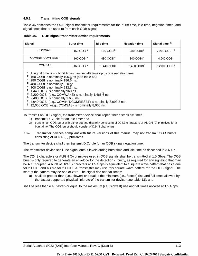
Serial Attached SCSI (SAS) Interface Manual, Rev. C (Draft 5) 113
4.5.1 Transmitting OOB signals
Table 46 describes the OOB signal transmitter requirements for the burst time, idle time, negation times, and signal times that are used to form each OOB signal.
To transmit an OOB signal, the transmitter device shall repeat these steps six times:1) transmit D.C. idle for an idle time; and2) transmit an OOB burst with either starting disparity consisting of D24.3 characters or ALIGN (0) primitives for a
burst time. The OOB burst should consist of D24.3 characters.
Note. Transmitter devices compliant with future versions of this manual may not transmit OOB bursts consisting of ALIGN (0) primitives.
The transmitter device shall then transmit D.C. idle for an OOB signal negation time.
The transmitter device shall use signal output levels during burst time and idle time as described in 3.6.4.7.
The D24.3 characters or ALIGN (0) primitives used in OOB signals shall be transmitted at 1.5 Gbps. The OOB burst is only required to generate an envelope for the detection circuitry, as required for any signaling that may be A.C. coupled. A burst of D24.3 characters at 1.5 Gbps is equivalent to a square wave pattern that has a one for 2 OOBI and a zero for 2 OOBI. A transmitter may use this square wave pattern for the OOB signal. The start of the pattern may be one or zero. The signal rise and fall times:
a) shall be greater than (i.e., slower) or equal to the minimum (i.e., fastest) rise and fall times allowed by the fastest supported physical link rate of the transmitter device (see table 13); and
shall be less than (i.e., faster) or equal to the maximum (i.e., slowest) rise and fall times allowed at 1.5 Gbps.
Table 46. OOB signal transmitter device requirements
Signal Burst time Idle time Negation time Signal time a
COMWAKE 160 OOBIb 160 OOBIb 280 OOBIc 2,200 OOBI g
COMINIT/COMRESET 160 OOBIb 480 OOBId 800 OOBIe 4,640 OOBIi
COMSAS 160 OOBIb 1,440 OOBIf 2,400 OOBIh 12,000 OOBIj
a A signal time is six burst times plus six idle times plus one negation time.b 160 OOBI is nominally 106.6 ns (see table 45).c 280 OOBI is nominally 186.6 ns.d 480 OOBI is nominally 320 ns.e 800 OOBI is nominally 533.3 ns.f 1,440 OOBI is nominally 960 ns.g 2,200 OOBI (e.g., COMWAKE) is nominally 1,466.6 ns.h 2,400 OOBI is nominally 1 600 ns.i 4,640 OOBI (e.g., COMINIT/COMRESET) is nominally 3,093.3 ns.j 12,000 OOBI (e.g., COMSAS) is nominally 8,000 ns.
Print Date:2010-Jan-13 11:56:37 CST Released; Prod Rel; C; 100293071 Seagate Confidential
114 Serial Attached SCSI (SAS) Interface Manual, Rev. C (Draft 5)
Figure 50 describes OOB signal transmission by the SP transmitter.
Figure 50. OOB signal transmission
COMRESET/COMINIT
COMWAKE
1 2 3 5 6
COMWAKEidle
COMSAS
4
OOB burst
1 2 3 5 64
COMWAKE negation
1 2 3 5 64
OOB burst
COMINIT idle
1 2 3 5 64
COMINIT negation
1 2 3 5 64
OOB burst
COMSAS idle
1 2 3 5 64
COMSAS negation
Time (not to scale)
OOB burstD.C. idle
Note: D.C. idle is shown here as a neutral signal for visual clarity only.
nth D.C. idle/OOB burst pair
Zero or more D.C. idle/OOB burst pairs n
Key:
Print Date:2010-Jan-13 11:56:37 CST Released; Prod Rel; C; 100293071 Seagate Confidential

Serial Attached SCSI (SAS) Interface Manual, Rev. C (Draft 5) 115
4.5.2 Receiving OOB signals
Table 47 describes the OOB signal receiver device requirements for detecting burst times, assuming Tburst is the length of the detected burst time. The burst time is not used to distinguish between signals.
Table 48 describes the OOB signal receiver device requirements for detecting idle times, assuming Tidle is the length of the detected idle time.
Table 49 describes the OOB signal receiver device requirements for detecting negation times, assuming Tidle is the length of the detected idle time.
Table 47. OOB signal receiver device burst time detection requirements
Signal a may detect shall detect
COMWAKE Tburst ≤ 100 ns Tburst > 100 ns
COMINIT/COMRESET Tburst ≤ 100 ns Tburst > 100 ns
COMSAS Tburst ≤ 100 ns Tburst > 100 ns
a Each burst time is transmitted as 160 OOBI, which is nominally 106.6 ns (see table 46).
Table 48. OOB signal receiver device idle time detection requirements
Signal may detect shall detect shall not detect
COMWAKEa 35 ns ≤ Tidle < 175 ns 101.3 ns ≤ Tidle ≤ 112 nsTidle< 35 ns orTidle 175 ns
COMINIT/COMRESETb 175 ns ≤ Tidle < 525 ns 304 ns ≤ Tidle ≤ 336 ns
Tidle < 175 ns orTidle 525 ns
COMSASc 525 ns ≤ Tidle < 1,575 ns 911.7 ns ≤ Tidle ≤ 1,008 nsTidle < 525 ns orTidle 1,575 ns
a COMWAKE idle time is transmitted as 160 OOBI, which is nominally 106.6 ns (see table 46).b COMINIT/COMRESET idle time is transmitted as 480 OOBI, which is nominally 320 ns.c COMSAS idle time is transmitted as 1,440 OOBI, which is nominally 960 ns.
Table 49. OOB signal receiver device negation time detection requirements
Signal shall detect
COMWAKEa Tidle > 175 ns
COMINIT/COMRESETb Tidle > 525 ns
COMSASc Tidle > 1,575 ns
a COMWAKE negation time is transmitted as 280 OOBI, which is nominally 186.6 ns (see table 46).b COMINIT/COMRESET negation time is transmitted as 800 OOBI is nominally 533.3 ns.c COMSAS negation time, which is transmitted as 2,400 OOBI, which is nominally 1,600 ns.
Print Date:2010-Jan-13 11:56:37 CST Released; Prod Rel; C; 100293071 Seagate Confidential

116 Serial Attached SCSI (SAS) Interface Manual, Rev. C (Draft 5)
A receiver device shall detect an OOB signal after receiving four consecutive idle time/burst time pairs (see figure 51) while it has not achieved dword synchronization, and may, but should not, detect an OOB signal after receiving four consecutive idle time/burst time pairs while it has achieved dword synchronization. It is not an error to receive more than four idle time/burst time pairs. A receiver device shall not detect the same OOB signal again until it has detected the corresponding negation time (e.g., a COMINIT negation time for a COMINIT) or has detected a different OOB signal (e.g., if a receiver device that previously detected COMINIT receives four sets of COMWAKE idle times followed by burst times, then it detects COMWAKE. The receiver device may then detect COMINIT again).
A SAS receiver device shall detect OOB bursts formed from any of the following:a) D24.3 characters at 1.5 Gbps;b) ALIGN (0) primitives at 1.5 Gbps; orc) ALIGN (0) primitives at 3 Gbps.
Note. ALIGN (0) primitives at 3 Gbps provide interoperability with transmitter devices compliant with pre-vious versions of this manual and SATA.
Print Date:2010-Jan-13 11:56:37 CST Released; Prod Rel; C; 100293071 Seagate Confidential
Serial Attached SCSI (SAS) Interface Manual, Rev. C (Draft 5) 117
Figure 51 describes SAS OOB signal detection by the SP receiver. The COMWAKE Detected, COMWAKE Completed, COMINIT Detected,
Figure 51. OOB signal detection
Expander devices shall not forward OOB signals. An expander device shall run the link reset sequence inde-pendently on each physical link.
COMRESET/COMINIT
COMWAKE
COMSAS
1 2 4
SPCOMWAKE
Detected
1 2 43COMINIT negation
SPCOMINIT Detected
OOB burstD.C. idle
1 2 43
COMSAS negation
SPCOMSAS Detected
Note: D.C. idle is shown here as a neutral signal for visual clarity only.
3
nth D.C. idle/OOB burst pair
n
n
n
Time (not to scale)
COMWAKE negation
Zero or more D.C. idle/OOB burst pairs n
Any transitions
Any transitions
Any transitions
Key:
Print Date:2010-Jan-13 11:56:37 CST Released; Prod Rel; C; 100293071 Seagate Confidential
118 Serial Attached SCSI (SAS) Interface Manual, Rev. C (Draft 5)
4.6 Phy reset sequences
4.6.1 Phy reset sequences overview
The phy reset sequence consists of:1) an OOB sequence (see 4.6.2.1);2) a speed negotiation sequence (see 4.6.2.2); and3) if the physical link is a SAS physical link and multiplexing (see 4.8) is enabled (see table 56), a multiplexing
sequence (see 4.6.2.3).
The phy reset sequence only affects the phy, not the port or device containing the phy or other phys in the same port or device.
The following are reasons to shall originate a phy reset sequence:a. power on;b. hard reset (i.e., receiving a HARD_RESET primitive sequence before an IDENTIFY address frame) (see
4.6.1);c. management application layer request;d. losing dword synchronization and not attempting to re-acquire dword synchronization;e. Receive Identify Timeout timer expires; orf. a hot-plug timeout (see 4.6.3) in an expander phy.
A SAS phy may originate a phy reset sequence after a hot-plug timeout (see 4.6.3).
After receiving a HARD_RESET primitive sequence before an IDENTIFY address frame, a phy should start the phy reset sequence within 250 ms.
Table 50 defines phy reset sequence timing parameters
Note. The drive does not implement Hot Plug Timeout. This is an initiator/expander function.
The drive originates a phy reset sequence after power on and hard reset (i.e., receiving a HARD_RESET).The drive originates a phy reset sequence within 250 ms after receiving a HARD_RESET.
The drive also originates a phy reset if it looses sync or if it does not receive IDENTIFY within 1 ms after com-pletion of the phy reset sequence.
Table 50. Phy reset sequence timing specifications
Parameter Minimum Maximum Comments
Hot-plug timeout 10 ms 500 ms
The time after which an expander phy shall retry an unsuc-cessful phy reset sequence, and after which a SAS initiator phy should retry an unsuccessful phy reset sequence (see 4.6.3).
Phy wakeup (partial) time na 10 µs
When a phy is in the partial phy power condition (see 2.5.1.5), the time within which a phy shall transmit a COM-WAKE after detecting a COMWAKE.
Phy wakeup (slumber) time na 10 ms
When a phy is in the slumber phy power condition (see 2.5.1.6), the time within which a phy shall transmit a COM-WAKE after detecting a COMWAKE.
Print Date:2010-Jan-13 11:56:37 CST Released; Prod Rel; C; 100293071 Seagate Confidential
Serial Attached SCSI (SAS) Interface Manual, Rev. C (Draft 5) 119
4.6.2 SAS to SAS phy reset sequence
4.6.2.1 SAS OOB sequence
To initiate a SAS OOB sequence a phy transmits a COMINIT.
On receipt of a COMINIT a phy either:a. if the receiving phy has not yet transmitted a COMINIT, transmit a COMINIT followed by a COMSAS; orb. if the receiving phy has transmitted a COMINIT, transmit a COMSAS.
On receipt of a COMSAS, if the receiving phy has not yet transmitted a COMSAS, the phy transmits a COM-SAS.
After completing the transmission of a COMSAS and the successful receipt a COMSAS the SAS OOB sequence is complete and the SAS speed negotiation sequence begins.
A phy detecting COMINIT and COMSAS continues with the SAS speed negotiation sequence after completing the SAS OOB sequence.
Print Date:2010-Jan-13 11:56:37 CST Released; Prod Rel; C; 100293071 Seagate Confidential
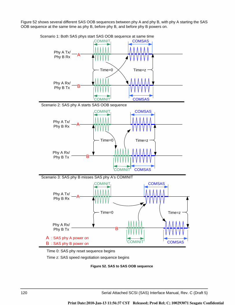
120 Serial Attached SCSI (SAS) Interface Manual, Rev. C (Draft 5)
Figure 52 shows several different SAS OOB sequences between phy A and phy B, with phy A starting the SAS OOB sequence at the same time as phy B, before phy B, and before phy B powers on.
Figure 52. SAS to SAS OOB sequence
COMSASCOMINIT
Scenario 1: Both SAS phys start SAS OOB sequence at same time
Scenario 2: SAS phy A starts SAS OOB sequence
COMINIT COMSAS
Time=0
COMSASCOMINIT
COMINIT COMSAS
Time=0
Time 0: SAS phy reset sequence begins
Time z: SAS speed negotiation sequence begins
: SAS phy A power onA: SAS phy B power onB
A
B
Phy A Tx/Phy B Rx
Phy A Rx/Phy B Tx
A
B
Phy A Tx/Phy B Rx
Phy A Rx/Phy B Tx
Time=z
Time=z
Scenario 3: SAS phy B misses SAS phy A’s COMINIT
COMSASCOMINIT
COMINIT COMSAS
Time=0
APhy A Tx/Phy B Rx
Phy A Rx/Phy B Tx
Time=z
B
Print Date:2010-Jan-13 11:56:37 CST Released; Prod Rel; C; 100293071 Seagate Confidential
Serial Attached SCSI (SAS) Interface Manual, Rev. C (Draft 5) 121
4.6.2.2 SAS speed negotiation sequence
4.6.2.2.1 SAS speed negotiation sequence overview
The SAS speed negotiation sequence establishes communications between the two phys of a physical link at the highest possible transmission rate.
The SAS speed negotiation sequence is a peer-to-peer negotiation technique that does not assume initiator and target (i.e., host and device) roles. The rules for speed negotiation are the same for both participating phys.
The SAS speed negotiation sequence consists of a set of speed negotiation windows (SNWs). Each SNW is identified by a name (e.g., Speed Negotiation Window-1 or SNW-1).
SNWs conform to one of three defined types:
a) speed negotiation without training: SNW-1, SNW-2 and Final-SNW (see 4.6.2.2.3.2);b) phy capabilities exchange: SNW-3 (see 4.6.2.2.3.3); andc) speed negotiation with training: Train-SNW (see 4.6.2.2.3.4).
Many of the timing parameters used for defining the SNWs are common to multiple SNW types. All of the timing specifications for all SNW types are defined in 4.6.2.2.2.
A SAS speed negotiation sequence may or may not include all three types of SNWs. Phys may implement a subset of SNWs provided that the subset implements a valid speed negotiation sequence. SAS speed negotiation sequences are defined in 4.6.2.2.4.
The transmitter device shall use SAS signal output levels during the SAS speed negotiation sequence as described in 3.6.4.7.
The phy shall not transmit deletable primitives for physical link rate tolerance management (see 5.3) during the SAS speed negotiation sequence.
Print Date:2010-Jan-13 11:56:37 CST Released; Prod Rel; C; 100293071 Seagate Confidential
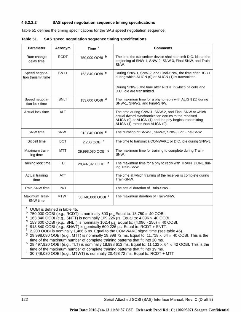
122 Serial Attached SCSI (SAS) Interface Manual, Rev. C (Draft 5)
4.6.2.2.2 SAS speed negotiation sequence timing specifications
Table 51 defines the timing specifications for the SAS speed negotiation sequence.
Table 51. SAS speed negotiation sequence timing specifications
Parameter Acronym Time a Comments
Rate change delay time
RCDT 750,000 OOBI b The time the transmitter device shall transmit D.C. idle at the beginning of SNW-1, SNW-2, SNW-3, Final-SNW, and Train-SNW.
Speed negotia-tion transmit time
SNTT 163,840 OOBI c During SNW-1, SNW-2, and Final-SNW, the time after RCDT during which ALIGN (0) or ALIGN (1) is transmitted.
During SNW-3, the time after RCDT in which bit cells and D.C. idle are transmitted.
Speed negotia-tion lock time
SNLT 153,600 OOBI d The maximum time for a phy to reply with ALIGN (1) during SNW-1, SNW-2, and Final-SNW.
Actual lock time ALT The time during SNW-1, SNW-2, and Final-SNW at which actual dword synchronization occurs to the received ALIGN (0) or ALIGN (1) and the phy begins transmitting ALIGN (1) rather than ALIGN (0).
SNW time SNWT 913,840 OOBI e The duration of SNW-1, SNW-2, SNW-3, or Final-SNW.
Bit cell time BCT 2,200 OOBI f The time to transmit a COMWAKE or D.C. idle during SNW-3.
Maximum train-ing time
MTT 29,998,080 OOBI g The maximum time for training to complete during Train-SNW.
Training lock time TLT 28,497,920 OOBI h The maximum time for a phy to reply with TRAIN_DONE dur-ing Train-SNW.
Actual training time
ATT The time at which training of the receiver is complete during Train-SNW.
Train-SNW time TWT The actual duration of Train-SNW.
Maximum Train-SNW time
MTWT 30,748,080 OOBI i The maximum duration of Train-SNW.
a OOBI is defined in table 45.b 750,000 OOBI (e.g., RCDT) is nominally 500 µs. Equal to: 18,750 × 40 OOBI.c 163,840 OOBI (e.g., SNTT) is nominally 109.226 µs. Equal to: 4,096 × 40 OOBI.d 153,600 OOBI (e.g., SNLT) is nominally 102.4 µs. Equal to: (4,096 - 256) × 40 OOBI.e 913,840 OOBI (e.g., SNWT) is nominally 609.226 µs. Equal to: RCDT + SNTT.f 2,200 OOBI is nominally 1,466.6 ns. Equal to the COMWAKE signal time (see table 46).g 29,998,080 OOBI (e.g., MTT) is nominally 19.998 72 ms. Equal to: 11,718 × 64 × 40 OOBI. This is the
time of the maximum number of complete training patterns that fit into 20 ms.h 28,497,920 OOBI (e.g., TLT) is nominally 18.998 613 ms. Equal to: 11,132 × 64 × 40 OOBI. This is the
time of the maximum number of complete training patterns that fit into 19 ms.i 30,748,080 OOBI (e.g., MTWT) is nominally 20.498 72 ms. Equal to: RCDT + MTT.
Print Date:2010-Jan-13 11:56:37 CST Released; Prod Rel; C; 100293071 Seagate Confidential
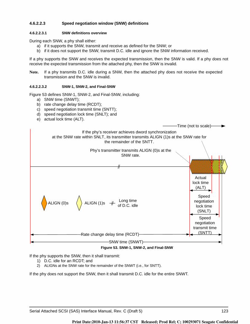
Serial Attached SCSI (SAS) Interface Manual, Rev. C (Draft 5) 123
4.6.2.2.3 Speed negotiation window (SNW) definitions
4.6.2.2.3.1 SNW definitions overview
During each SNW, a phy shall either:a) if it supports the SNW, transmit and receive as defined for the SNW; orb) if it does not support the SNW, transmit D.C. idle and ignore the SNW information received.
If a phy supports the SNW and receives the expected transmission, then the SNW is valid. If a phy does not receive the expected transmission from the attached phy, then the SNW is invalid.
Note. If a phy transmits D.C. idle during a SNW, then the attached phy does not receive the expected transmission and the SNW is invalid.
4.6.2.2.3.2 SNW-1, SNW-2, and Final-SNW
Figure 53 defines SNW-1, SNW-2, and Final-SNW, including:a) SNW time (SNWT);b) rate change delay time (RCDT);c) speed negotiation transmit time (SNTT);d) speed negotiation lock time (SNLT); ande) actual lock time (ALT).
Figure 53. SNW-1, SNW-2, and Final-SNW
If the phy supports the SNW, then it shall transmit:1) D.C. idle for an RCDT; and2) ALIGNs at the SNW rate for the remainder of the SNWT (i.e., for SNTT).
If the phy does not support the SNW, then it shall transmit D.C. idle for the entire SNWT.
Phy’s transmitter transmits ALIGN (0)s at the SNW rate.
If the phy’s receiver achieves dword synchronizationat the SNW rate within SNLT, its transmitter transmits ALIGN (1)s at the SNW rate for
the remainder of the SNTT.
Speed negotiation lock time (SNLT)
Speed negotiation
transmit time (SNTT)
SNW time (SNWT)
Rate change delay time (RCDT)
ALIGN (0)s ALIGN (1)s Long time of D.C. idle
Time (not to scale)
Actuallock time
(ALT)
Print Date:2010-Jan-13 11:56:37 CST Released; Prod Rel; C; 100293071 Seagate Confidential
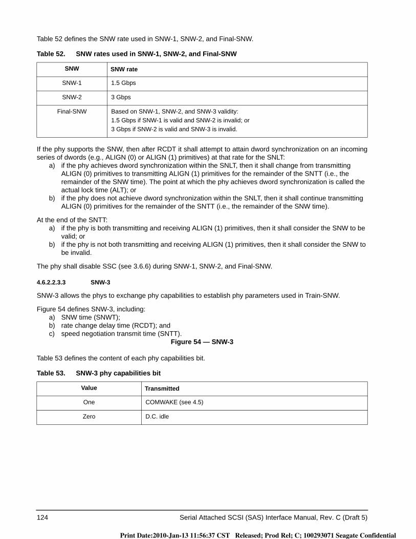
124 Serial Attached SCSI (SAS) Interface Manual, Rev. C (Draft 5)
Table 52 defines the SNW rate used in SNW-1, SNW-2, and Final-SNW.
If the phy supports the SNW, then after RCDT it shall attempt to attain dword synchronization on an incoming series of dwords (e.g., ALIGN (0) or ALIGN (1) primitives) at that rate for the SNLT:
a) if the phy achieves dword synchronization within the SNLT, then it shall change from transmitting ALIGN (0) primitives to transmitting ALIGN (1) primitives for the remainder of the SNTT (i.e., the remainder of the SNW time). The point at which the phy achieves dword synchronization is called the actual lock time (ALT); or
b) if the phy does not achieve dword synchronization within the SNLT, then it shall continue transmitting ALIGN (0) primitives for the remainder of the SNTT (i.e., the remainder of the SNW time).
At the end of the SNTT:a) if the phy is both transmitting and receiving ALIGN (1) primitives, then it shall consider the SNW to be
valid; orb) if the phy is not both transmitting and receiving ALIGN (1) primitives, then it shall consider the SNW to
be invalid.
The phy shall disable SSC (see 3.6.6) during SNW-1, SNW-2, and Final-SNW.
4.6.2.2.3.3 SNW-3
SNW-3 allows the phys to exchange phy capabilities to establish phy parameters used in Train-SNW.
Figure 54 defines SNW-3, including:a) SNW time (SNWT);b) rate change delay time (RCDT); andc) speed negotiation transmit time (SNTT).
Figure 54 — SNW-3
Table 53 defines the content of each phy capabilities bit.
Table 52. SNW rates used in SNW-1, SNW-2, and Final-SNW
SNW SNW rate
SNW-1 1.5 Gbps
SNW-2 3 Gbps
Final-SNW Based on SNW-1, SNW-2, and SNW-3 validity:1.5 Gbps if SNW-1 is valid and SNW-2 is invalid; or3 Gbps if SNW-2 is valid and SNW-3 is invalid.
Table 53. SNW-3 phy capabilities bit
Value Transmitted
One COMWAKE (see 4.5)
Zero D.C. idle
Print Date:2010-Jan-13 11:56:37 CST Released; Prod Rel; C; 100293071 Seagate Confidential
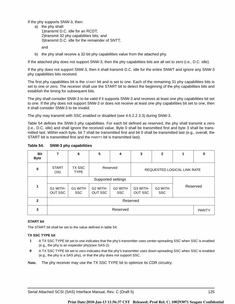
Serial Attached SCSI (SAS) Interface Manual, Rev. C (Draft 5) 125
If the phy supports SNW-3, then:a) the phy shall:
1)transmit D.C. idle for an RCDT;2)transmit 32 phy capabilities bits; and3)transmit D.C. idle for the remainder of SNTT;
and
b) the phy shall receive a 32-bit phy capabilities value from the attached phy.
If the attached phy does not support SNW-3, then the phy capabilities bits are all set to zero (i.e., D.C. idle).
If the phy does not support SNW-3, then it shall transmit D.C. idle for the entire SNWT and ignore any SNW-3 phy capabilities bits received.
The first phy capabilities bit is the START bit and is set to one. Each of the remaining 31 phy capabilities bits is set to one or zero. The receiver shall use the START bit to detect the beginning of the phy capabilities bits and establish the timing for subsequent bits.
The phy shall consider SNW-3 to be valid if it supports SNW-3 and receives at least one phy capabilities bit set to one. If the phy does not support SNW-3 or does not receive at least one phy capabilities bit set to one, then it shall consider SNW-3 to be invalid.
The phy may transmit with SSC enabled or disabled (see 4.6.2.2.3.3) during SNW-3.
Table 54 defines the SNW-3 phy capabilities. For each bit defined as reserved, the phy shall transmit a zero (i.e., D.C. idle) and shall ignore the received value. Byte 0 shall be transmitted first and byte 3 shall be trans-mitted last. Within each byte, bit 7 shall be transmitted first and bit 0 shall be transmitted last (e.g., overall, the START bit is transmitted first and the PARITY bit is transmitted last).
START bitThe START bit shall be set to the value defined in table 54.
TX SSC TYPE bit 1 A TX SSC TYPE bit set to one indicates that the phy’s transmitter uses center-spreading SSC when SSC is enabled
(e.g., the phy is an expander phy)(see SAS-2). 0 A TX SSC TYPE bit set to zero indicates that the phy’s transmitter uses down-spreading SSC when SSC is enabled
(e.g., the phy is a SAS phy), or that the phy does not support SSC.
Note. The phy receiver may use the TX SSC TYPE bit to optimize its CDR circuitry.
Table 54. SNW-3 phy capabilities
BitByte
7 6 5 4 3 2 1 0
0 START (1b)
TX SSC TYPE
Reserved REQUESTED LOGICAL LINK RATE
1
Supported settings
ReservedG1 WITH-OUT SSC
G1 WITH SSC
G2 WITH-OUT SSC
G2 WITH SSC
G3 WITH-OUT SSC
G3 WITH SSC
2 Reserved
3 Reserved PARITY
Print Date:2010-Jan-13 11:56:37 CST Released; Prod Rel; C; 100293071 Seagate Confidential
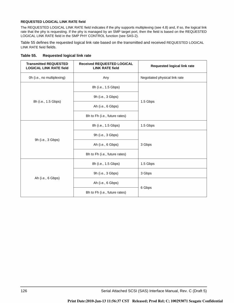
126 Serial Attached SCSI (SAS) Interface Manual, Rev. C (Draft 5)
REQUESTED LOGICAL LINK RATE fieldThe REQUESTED LOGICAL LINK RATE field indicates if the phy supports multiplexing (see 4.8) and, if so, the logical link rate that the phy is requesting. If the phy is managed by an SMP target port, then the field is based on the REQUESTED LOGICAL LINK RATE field in the SMP PHY CONTROL function (see SAS-2).
Table 55 defines the requested logical link rate based on the transmitted and received REQUESTED LOGICAL LINK RATE field fields.
Table 55. Requested logical link rate
Transmitted REQUESTED LOGICAL LINK RATE field
Received REQUESTED LOGICAL LINK RATE field Requested logical link rate
0h (i.e., no multiplexing) Any Negotiated physical link rate
8h (i.e., 1.5 Gbps)
8h (i.e., 1.5 Gbps)
1.5 Gbps9h (i.e., 3 Gbps)
Ah (i.e., 6 Gbps)
Bh to Fh (i.e., future rates)
9h (i.e., 3 Gbps)
8h (i.e., 1.5 Gbps) 1.5 Gbps
9h (i.e., 3 Gbps)
3 GbpsAh (i.e., 6 Gbps)
Bh to Fh (i.e., future rates)
Ah (i.e., 6 Gbps)
8h (i.e., 1.5 Gbps) 1.5 Gbps
9h (i.e., 3 Gbps) 3 Gbps
Ah (i.e., 6 Gbps)6 Gbps
Bh to Fh (i.e., future rates)
Print Date:2010-Jan-13 11:56:37 CST Released; Prod Rel; C; 100293071 Seagate Confidential
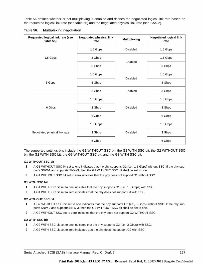
Serial Attached SCSI (SAS) Interface Manual, Rev. C (Draft 5) 127
Table 56 defines whether or not multiplexing is enabled and defines the negotiated logical link rate based on the requested logical link rate (see table 55) and the negotiated physical link rate (see SAS-2).
The supported settings bits include the G1 WITHOUT SSC bit, the G1 WITH SSC bit, the G2 WITHOUT SSCbit, the G2 WITH SSC bit, the G3 WITHOUT SSC bit, and the G3 WITH SSC bit.
G1 WITHOUT SSC bit 1 A G1 WITHOUT SSC bit set to one indicates that the phy supports G1 (i.e., 1.5 Gbps) without SSC. If the phy sup-
ports SNW-1 and supports SNW-3, then the G1 WITHOUT SSC bit shall be set to one. 0 A G1 WITHOUT SSC bit set to zero indicates that the phy does not support G1 without SSC.
G1 WITH SSC bit 1 A G1 WITH SSC bit set to one indicates that the phy supports G1 (i.e., 1.5 Gbps) with SSC.
0 A G1 WITH SSC bit set to zero indicates that the phy does not support G1 with SSC.
G2 WITHOUT SSC bit 1 A G2 WITHOUT SSC bit set to one indicates that the phy supports G2 (i.e., 3 Gbps) without SSC. If the phy sup-
ports SNW-2 and supports SNW-3, then the G2 WITHOUT SSC bit shall be set to one. 0 A G2 WITHOUT SSC set to zero indicates that the phy does not support G2 WITHOUT SSC.
G2 WITH SSC bit 1 A G2 WITH SSC bit set to one indicates that the phy supports G2 (i.e., 3 Gbps) with SSC.
0 A G2 WITH SSC bit set to zero indicates that the phy does not support G2 with SSC.
Table 56. Multiplexing negotiation
Requested logical link rate (see table 55)
Negotiated physical link rate Multiplexing Negotiated logical link
rate
1.5 Gbps
1.5 Gbps Disabled 1.5 Gbps
3 GbpsEnabled
1.5 Gbps
6 Gbps 3 Gbps
3 Gbps
1.5 GbpsDisabled
1.5 Gbps
3 Gbps 3 Gbps
6 Gbps Enabled 3 Gbps
6 Gbps
1.5 Gbps
Disabled
1.5 Gbps
3 Gbps 3 Gbps
6 Gbps 6 Gbps
Negotiated physical link rate
1.5 Gbps
Disabled
1.5 Gbps
3 Gbps 3 Gbps
6 Gbps 6 Gbps
Print Date:2010-Jan-13 11:56:37 CST Released; Prod Rel; C; 100293071 Seagate Confidential
128 Serial Attached SCSI (SAS) Interface Manual, Rev. C (Draft 5)
G3 WITHOUT SSC bit 1 A G3 WITHOUT SSC bit set to one indicates that the phy supports G3 (i.e., 6 Gbps) without SSC.
0 A G3 WITHOUT SSC bit set to zero indicates that the phy does not support G3 without SSC.
G3 WITH SSC bit 1 A G3 WITH SSC bit set to one indicates that the phy supports G3 (i.e., 6 Gbps) with SSC.
0 A G3 WITH SSC bit set to zero indicates that the phy does not support G3 with SSC.
Table 57 defines the priority of the supported settings bits.
PARITY bitThe PARITY bit provides for error detection of all the SNW-3 phy capabilities bits. The PARITY bit shall be set to one or zero such that the total number of SNW-3 phy capabilities bits that are set to one is even, including the START bit and the PARITY bit. If the PARITY bit received is incorrect based upon the received SNW phy capabilities bits, then the parity is bad and the phy shall consider a phy reset problem (see SAS-2) to have occurred.
4.6.2.2.3.4 Train-SNW
Figure 55 defines the Train-SNW, including:
a) maximum Train-SNW window time (MTWT);b) rate change delay time (RCDT);c) maximum train time (MTT);d) train lock time (TLT); and
Table 57. Supported settings bit priorities
Priority Bit
Highest G3 WITH SSC bit
... G3 WITHOUT SSC bit
... G2 WITH SSC bit
... G2 WITHOUT SSC bit
... G1 WITH SSC bit
Lowest G1 WITHOUT SSC bit
Print Date:2010-Jan-13 11:56:37 CST Released; Prod Rel; C; 100293071 Seagate Confidential
Serial Attached SCSI (SAS) Interface Manual, Rev. C (Draft 5) 129
e) actual training time (ATT).
Figure 55. Train-SNW
The Train-SNW contains training patterns formed by TRAIN and TRAIN_DONE (see 5.2.6.15 and 5.2.6.16) as defined in table 58.
The scrambler is the same as that defined for the link layer (see 5.6) and shall be initialized at the end of RCDT. The scrambler shall not be reinitialized for the remainder of the Train-SNW.
The phy shall start transmitting TRAIN patterns at the end of RCDT. The first TRAIN pattern may have either starting disparity. The number of TRAIN patterns transmitted is determined by the time required for the phy’s receiver to complete training and acquire dword synchronization. The phy shall transmit at least one TRAIN pattern and shall transmit a minimum of four TRAIN_DONE patterns.
Table 58. Training patterns
Training pattern Description
TRAIN patternSequence of:
1) TRAIN primitive sequence; and2) 58 dwords set to 00000000h that are transmitted scrambled and 8b10b encoded.
TRAIN_DONE pat-tern
Sequence of:1) TRAIN_DONE primitive sequence; and2) 58 dwords set to 00000000h that are transmitted scrambled and 8b10b encoded.
Maximum Train-SNW time (MTWT)
Rate change delay time (RCDT)
Scrambled training data
Long time of D.C. idle
Time (not to scale)
Maximum training time (MTT)
TRAIN_DONE primitive
TRAINprimitive
Actual training time (ATT)
Dwords fromLink LayerTRAIN
pattern
TRAIN_DONE pattern
Training lock time (TLT)
Train-SNW time (TWT)
TRAIN_DONE received
Receiver trained and dword synchronization acquired
Print Date:2010-Jan-13 11:56:37 CST Released; Prod Rel; C; 100293071 Seagate Confidential
130 Serial Attached SCSI (SAS) Interface Manual, Rev. C (Draft 5)
After RCDT, the phy shall attempt to attain dword synchronization using the commonly supported settings on an incoming series of dwords:
a) if the phy achieves dword synchronization within the TLT, then, after completing transmission of the current TRAIN pattern, it shall change from transmitting TRAIN patterns to transmitting TRAIN_DONE patterns for the remainder of the TWT (i.e., the remainder of the SNW time). The point at which the phy achieves dword synchronization is called the actual training time (ATT); or
b) if the phy does not achieve dword synchronization within the TLT, then it shall continue transmitting TRAIN patterns for the remainder of the TWTT (i.e., the remainder of the SNW time).
The phy shall not perform pattern comparison on the data dwords in the training pattern.
If the phy:a) transmits four or more TRAIN_DONE patterns; andb) receives a minimum of one TRAIN_DONE primitive sequence before MTT,
then the phy shall:a) after completing transmission of the current TRAIN_DONE pattern, transmit at least one more
TRAIN_DONE pattern, stop transmitting TRAIN_DONE patterns, and start transmitting dwords from the link layer; and
b) consider the Train-SNW to be valid.
If the phy does not receive a TRAIN_DONE primitive sequence before MTT and transmits four or more TRAIN_DONE patterns, then it shall consider the Train-SNW to be invalid.
Print Date:2010-Jan-13 11:56:37 CST Released; Prod Rel; C; 100293071 Seagate Confidential
Serial Attached SCSI (SAS) Interface Manual, Rev. C (Draft 5) 131
4.6.2.2.4 SAS speed negotiation sequence
The SAS speed negotiation sequence consists of a set of SNWs (see 4.6.2.2.3) in the order shown in figure 56.
Figure 56. SAS speed negotiation sequence SNW flowchart
SNW-1 valid and SNW-2 invalid?
EndYes
Train-SNW invalid and
another commonly supported setting?
No
Yes
SNW-2 valid?
No
Yes
No
Yes
No
SNW-2
SNW-3
Final-SNW
Train-SNW
Parity good and a commonly supported setting?
Yes
No
SNW-3 valid?
SNW-1Start
No
SNW-1 not D.C. idle and SNW-2 D.C.
idle
Yes (should)
Print Date:2010-Jan-13 11:56:37 CST Released; Prod Rel; C; 100293071 Seagate Confidential

132 Serial Attached SCSI (SAS) Interface Manual, Rev. C (Draft 5)
A phy shall not support the following combinations of supported SNWs:a) no SNWs; andb) SNW-1 and SNW-3 only.
Note. If SNW-1 is successful and the combination of SNW-1 and SNW-3 only is used, then the phy is not able to reach SNW-3.
A phy should detect whether the physical link is D.C. idle during SNW-1 and SNW-2, even if the phy does not support that SNW. If the phy detects:
a) SNW-1 is not D.C. idle; andb) SNW-2 is D.C. idle,
then it should end the speed negotiation sequence without progressing to SNW-3.
Train-SNW is based on the highest untried commonly supported settings based on the outgoing and incoming SNW-3 supported settings bits (see 4.6.2.2.3).
If a Train-SNW is invalid and there are additional, untried, commonly supported settings exchanged during SNW-3, then a new Train-SNW shall be performed based on the next highest, untried, commonly supported settings.
A phy reset problem occurs:c) after Final-SNW, if Final-SNW is invalid;d) after SNW-3, if SNW-3 is valid and the parity is bad; ore) after a Train-SNW, if the Train-SNW is invalid and there are no additional, untried, commonly
supported settings.
Phy reset problems terminate the SAS speed negotiation sequence and are counted and reported in the PHY RESET PROBLEM COUNT field in the SMP REPORT PHY ERROR LOG page (see SAS-2) and the Protocol-Specific Port log page (see 8.1.5).
4.6.2.2.5 SAS speed negotiation sequence examples
Figure 57 shows speed negotiation between a phy A and a phy B where both phys participate in:1) SNW-1, supported by both phys;2) SNW-2, supported by both phys;3) SNW-3, supported by both phys; and4) Train-SNW.
After phy A and phy B detect:a) SNW-1 valid;b) SNW-2 valid; andc) SNW-3 valid,
Print Date:2010-Jan-13 11:56:37 CST Released; Prod Rel; C; 100293071 Seagate Confidential
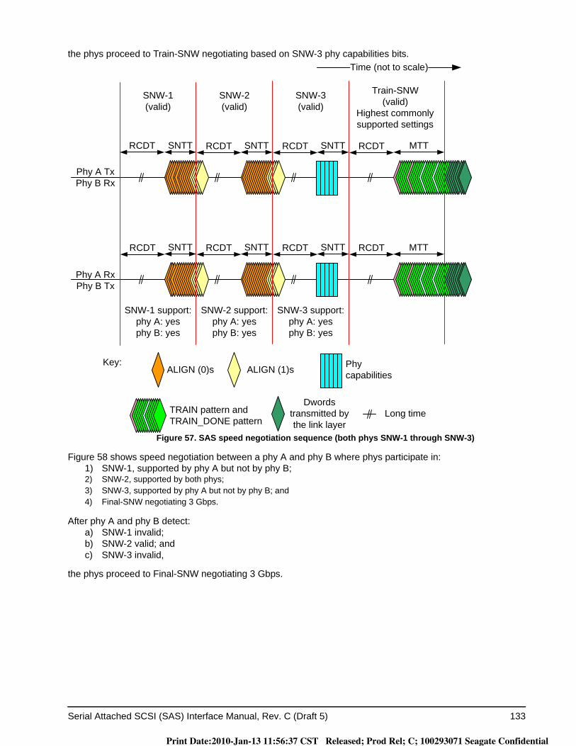
Serial Attached SCSI (SAS) Interface Manual, Rev. C (Draft 5) 133
the phys proceed to Train-SNW negotiating based on SNW-3 phy capabilities bits.
Figure 57. SAS speed negotiation sequence (both phys SNW-1 through SNW-3)
Figure 58 shows speed negotiation between a phy A and phy B where phys participate in:1) SNW-1, supported by phy A but not by phy B;2) SNW-2, supported by both phys;3) SNW-3, supported by phy A but not by phy B; and4) Final-SNW negotiating 3 Gbps.
After phy A and phy B detect:a) SNW-1 invalid;b) SNW-2 valid; andc) SNW-3 invalid,
the phys proceed to Final-SNW negotiating 3 Gbps.
ALIGN (0)s ALIGN (1)s
Phy A RxPhy B Tx
Phy A TxPhy B Rx
SNW-1 support:phy A: yesphy B: yes
Time (not to scale)
SNTT
SNTT SNTT
SNW-1(valid)
SNW-2(valid)
SNW-3(valid)
Train-SNW(valid)
Highest commonly supported settings
SNW-2 support:phy A: yesphy B: yes
SNW-3 support:phy A: yesphy B: yes
Dwords transmitted by the link layer
Long time
SNTTSNTT
SNTT
Phy capabilities
MTT
MTT
RCDT RCDT RCDT
RCDT RCDT RCDT RCDT
RCDT
TRAIN pattern and TRAIN_DONE pattern
Key:
Print Date:2010-Jan-13 11:56:37 CST Released; Prod Rel; C; 100293071 Seagate Confidential
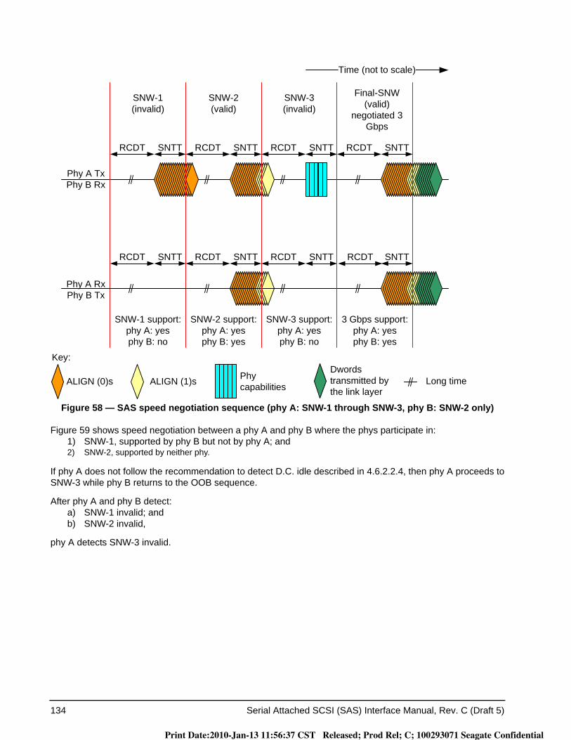
134 Serial Attached SCSI (SAS) Interface Manual, Rev. C (Draft 5)
Figure 58 — SAS speed negotiation sequence (phy A: SNW-1 through SNW-3, phy B: SNW-2 only)
Figure 59 shows speed negotiation between a phy A and phy B where the phys participate in:1) SNW-1, supported by phy B but not by phy A; and2) SNW-2, supported by neither phy.
If phy A does not follow the recommendation to detect D.C. idle described in 4.6.2.2.4, then phy A proceeds to SNW-3 while phy B returns to the OOB sequence.
After phy A and phy B detect:a) SNW-1 invalid; andb) SNW-2 invalid,
phy A detects SNW-3 invalid.
ALIGN (0)s ALIGN (1)s
Phy A RxPhy B Tx
Phy A TxPhy B Rx
SNW-1 support:phy A: yesphy B: no
Time (not to scale)
SNTT SNTT SNTT
SNTT SNTT SNTTSNTT
SNW-1(invalid)
SNW-2(valid)
SNW-3(invalid)
Final-SNW (valid)
negotiated 3 Gbps
SNW-2 support:phy A: yesphy B: yes
SNW-3 support:phy A: yesphy B: no
3 Gbps support:phy A: yesphy B: yes
Dwords transmitted by the link layer
Long time
SNTT
Phy capabilities
RCDT
RCDT RCDT
RCDT
RCDT
RCDT
RCDT
RCDT
Key:
Print Date:2010-Jan-13 11:56:37 CST Released; Prod Rel; C; 100293071 Seagate Confidential
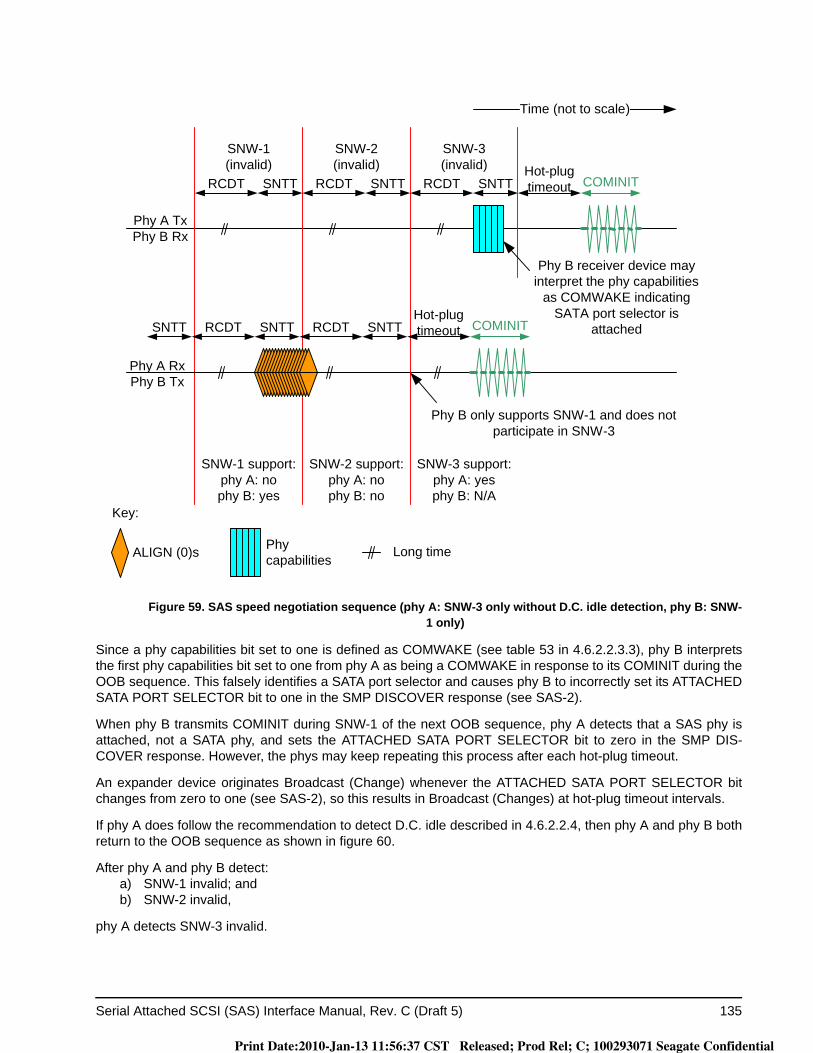
Serial Attached SCSI (SAS) Interface Manual, Rev. C (Draft 5) 135
Figure 59. SAS speed negotiation sequence (phy A: SNW-3 only without D.C. idle detection, phy B: SNW-1 only)
Since a phy capabilities bit set to one is defined as COMWAKE (see table 53 in 4.6.2.2.3.3), phy B interprets the first phy capabilities bit set to one from phy A as being a COMWAKE in response to its COMINIT during the OOB sequence. This falsely identifies a SATA port selector and causes phy B to incorrectly set its ATTACHED SATA PORT SELECTOR bit to one in the SMP DISCOVER response (see SAS-2).
When phy B transmits COMINIT during SNW-1 of the next OOB sequence, phy A detects that a SAS phy is attached, not a SATA phy, and sets the ATTACHED SATA PORT SELECTOR bit to zero in the SMP DIS-COVER response. However, the phys may keep repeating this process after each hot-plug timeout.
An expander device originates Broadcast (Change) whenever the ATTACHED SATA PORT SELECTOR bit changes from zero to one (see SAS-2), so this results in Broadcast (Changes) at hot-plug timeout intervals.
If phy A does follow the recommendation to detect D.C. idle described in 4.6.2.2.4, then phy A and phy B both return to the OOB sequence as shown in figure 60.
After phy A and phy B detect:a) SNW-1 invalid; andb) SNW-2 invalid,
phy A detects SNW-3 invalid.
ALIGN (0)s
Phy A RxPhy B Tx
Phy A TxPhy B Rx
SNW-1 support:phy A: nophy B: yes
Time (not to scale)
SNTT SNTT
SNW-1(invalid)
SNW-2(invalid)
SNW-3(invalid)
SNW-2 support:phy A: nophy B: no
SNW-3 support:phy A: yesphy B: N/A
Long time
SNTT
Phy capabilities
RCDT
RCDT RCDT RCDT
RCDT SNTT
SNTTSNTTHot-plug timeout COMINIT
Hot-plug timeout COMINIT
Phy B receiver device may interpret the phy capabilities
as COMWAKE indicating SATA port selector is
attached
Phy B only supports SNW-1 and does not participate in SNW-3
Key:
Print Date:2010-Jan-13 11:56:37 CST Released; Prod Rel; C; 100293071 Seagate Confidential
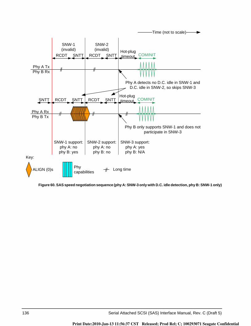
136 Serial Attached SCSI (SAS) Interface Manual, Rev. C (Draft 5)
Figure 60. SAS speed negotiation sequence (phy A: SNW-3 only with D.C. idle detection, phy B: SNW-1 only)
ALIGN (0)s
Phy A RxPhy B Tx
Phy A TxPhy B Rx
SNW-1 support:phy A: nophy B: yes
Time (not to scale)
SNTT SNTT
SNW-1(invalid)
SNW-2(invalid)
SNW-2 support:phy A: nophy B: no
SNW-3 support:phy A: yesphy B: N/A
Long timePhy capabilities
RCDT
RCDT RCDT
RCDT SNTT
SNTTSNTTHot-plug timeout COMINIT
Hot-plug timeout COMINIT
Phy B only supports SNW-1 and does not participate in SNW-3
Phy A detects no D.C. idle in SNW-1 and D.C. idle in SNW-2, so skips SNW-3
Key:
Print Date:2010-Jan-13 11:56:37 CST Released; Prod Rel; C; 100293071 Seagate Confidential
Serial Attached SCSI (SAS) Interface Manual, Rev. C (Draft 5) 137
Figure 61 shows a speed negotiation sequence where phy B does not achieve dword synchronization during Final-SNW, creating a phy reset problem. If this occurs, then the handshake is not complete and the phy reset sequence is retried.
Figure 61. SAS speed negotiation sequence - phy reset problem in Final-SNW
COMINIT
ALIGN (0)s ALIGN (1)s
Phy A RxPhy B Tx
Phy A TxPhy B Rx
SNW-1 support:phy A: yesphy B: yes
Time (not to scale)
SNTT SNTT
SNTT SNTT
SNW-1(valid)
SNW-2(valid)
SNW-3(invalid)
Final-SNW(invalid)
negotiated 3 Gbps
SNW-2 support:phy A: yesphy B: yes
SNW-3 support:phy A: yesphy B: no
Long time
SNTTSNTT
SNTT SNTTHot-plug timeout
Hot-plug timeout
COMINIT
Phy B receiver fails to achieve dword
synchronization, so its transmitter does not transmit ALIGN (1)s.
Phy capabilities
RCDT RCDT
RCDT RCDT
RCDT
RCDT
RCDT
RCDT
Key:
Print Date:2010-Jan-13 11:56:37 CST Released; Prod Rel; C; 100293071 Seagate Confidential
138 Serial Attached SCSI (SAS) Interface Manual, Rev. C (Draft 5)
Figure 62 shows a speed negotiation sequence in which a phy reset problem is encountered in SNW-3 because the phys do not exchange the phy capabilities bits properly (e.g., due to a parity error).
Figure 62. SAS speed negotiation sequence - phy reset problem in SNW-3
Figure 63 shows a speed negotiation sequence in which a phy reset problem is encountered in Train-SNW because either phy does not complete training within MTT. This example assumes that only one commonly supported setting is exchanged in the phy capabilities bits.
ALIGN (0)s ALIGN (1)s
Phy A RxPhy B Tx
Phy A TxPhy B Rx
SNW-1 support:phy A: yesphy B: yes
Time (not to scale)
RCDT SNTT RCDTRCDT
RCDT RCDT SNTT RCDT SNTT
SNW-1(valid)
SNW-2(valid)
SNW-3(valid)
SNW-2 support:phy A: yesphy B: yes
SNW-3 support:phy A: yesphy B: yes
Long time
SNTTSNTT
SNTT
Phy capabilities
Hot-plug timeout COMINIT
Phy A receiver device receives phy capabilities with bad parity
RCDT MTT
Phy A: Phy reset problem
Phy B: Train-SNW
TRAIN pattern and TRAIN_DONE pattern
Key:
Print Date:2010-Jan-13 11:56:37 CST Released; Prod Rel; C; 100293071 Seagate Confidential
Serial Attached SCSI (SAS) Interface Manual, Rev. C (Draft 5) 139
Figure 63. SAS speed negotiation sequence - phy reset problem in Train-SNW
ALIGN (0)s ALIGN (1)s
Phy A RxPhy B Tx
Phy A TxPhy B Rx
SNW-1 support:phy A: yesphy B: yes
Time (not to scale)
RCDT SNTT RCDT RCDTRCDT
RCDT RCDT SNTT RCDTRCDT SNTT
SNW-1(valid)
SNW-2(valid)
SNW-3(valid)
Train-SNW(invalid)
highest commonly supported rate
SNW-2 support:phy A: yesphy B: yes
SNW-3 support:phy A: yesphy B: yes
Long time
SNTTSNTT
SNTT
Phy capabilities
TRAIN pattern and TRAIN_DONE pattern
MTT COMINIT
Hot-plug timeout
Hot-plug timeout
COMINITMTT
Phy A receiver device fails to train within TLT
or phy B transmitter fails to transmit the
training pattern properlyand there are no
additional commonly supported settings
Key:
Print Date:2010-Jan-13 11:56:37 CST Released; Prod Rel; C; 100293071 Seagate Confidential
140 Serial Attached SCSI (SAS) Interface Manual, Rev. C (Draft 5)
Figure 64 shows two Train-SNWs, where supported settings bits are exchanged that contain more than one commonly supported setting and the Train-SNW using the highest commonly supported setting is invalid, so a second Train-SNW is performed using the next highest commonly supported setting.
Figure 64. SAS speed negotiation sequence - multiple Train-SNWs
For more examples of SAS speed negotiations, see SAS_2.
4.6.2.3 Multiplexing sequence
If SNW-3 indicates multiplexing (see 4.8) is enabled (see table 56), then the phy shall transmit the multiplexing sequence immediately after the speed negotiation sequence.
The multiplexing sequence is:1) MUX (LOGICAL LINK 0);2) MUX (LOGICAL LINK 1);3) MUX (LOGICAL LINK 0);4) MUX (LOGICAL LINK 1);5) MUX (LOGICAL LINK 0); and6) MUX (LOGICAL LINK 1).
The phy shall not transmit deletable primitives for physical link rate tolerance management (see 5.3.1) during the multiplexing sequence.
ALIGN (0)s ALIGN (1)s
Phy A RxPhy B Tx
Phy A TxPhy B Rx
SNW-1 support:phy A: yesphy B: yes
Time (not to scale)
RCDT SNTT RCDT RCDTRCDT
RCDT RCDT SNTT RCDTRCDT SNTT
SNW-1(valid)
SNW-2(valid)
SNW-3(valid)
First Train-SNW(invalid)
highest commonly supported setting
SNW-2 support:phy A: yesphy B: yes
SNW-3 support:phy A: yesphy B: yes
Long time
SNTTSNTT
SNTT
Phy capabilities
MTT
MTT
Phy A receiver device fails to train
within MTT or phy B transmitter fails to
transmit the training pattern properly during the first
Train-SNW (i.e, the first Train-SNW is invalid), there is
another commonly supported setting,
and the second Train-SNW is valid.
RCDT
RCDT MTT
MTT
Second Train-SNW(valid)
next highest commonly supported setting
TRAIN pattern and TRAIN_DONE pattern
Key:
Print Date:2010-Jan-13 11:56:37 CST Released; Prod Rel; C; 100293071 Seagate Confidential
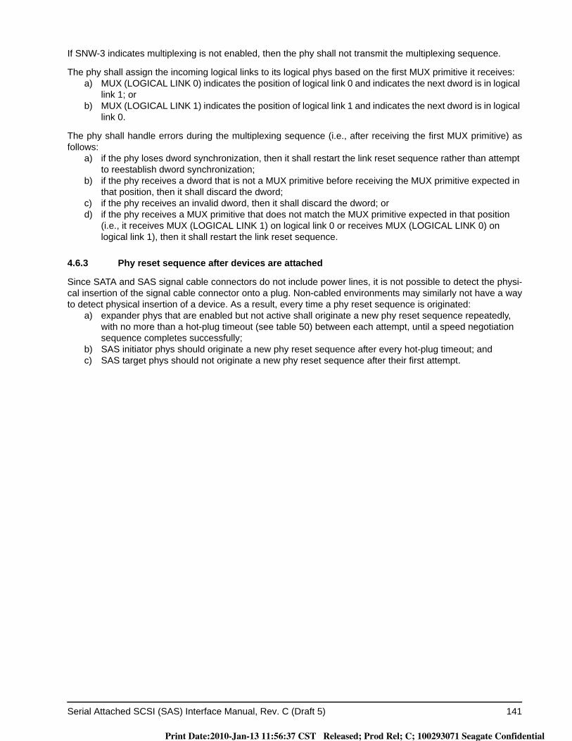
Serial Attached SCSI (SAS) Interface Manual, Rev. C (Draft 5) 141
If SNW-3 indicates multiplexing is not enabled, then the phy shall not transmit the multiplexing sequence.
The phy shall assign the incoming logical links to its logical phys based on the first MUX primitive it receives:a) MUX (LOGICAL LINK 0) indicates the position of logical link 0 and indicates the next dword is in logical
link 1; orb) MUX (LOGICAL LINK 1) indicates the position of logical link 1 and indicates the next dword is in logical
link 0.
The phy shall handle errors during the multiplexing sequence (i.e., after receiving the first MUX primitive) as follows:
a) if the phy loses dword synchronization, then it shall restart the link reset sequence rather than attempt to reestablish dword synchronization;
b) if the phy receives a dword that is not a MUX primitive before receiving the MUX primitive expected in that position, then it shall discard the dword;
c) if the phy receives an invalid dword, then it shall discard the dword; ord) if the phy receives a MUX primitive that does not match the MUX primitive expected in that position
(i.e., it receives MUX (LOGICAL LINK 1) on logical link 0 or receives MUX (LOGICAL LINK 0) on logical link 1), then it shall restart the link reset sequence.
4.6.3 Phy reset sequence after devices are attached
Since SATA and SAS signal cable connectors do not include power lines, it is not possible to detect the physi-cal insertion of the signal cable connector onto a plug. Non-cabled environments may similarly not have a way to detect physical insertion of a device. As a result, every time a phy reset sequence is originated:
a) expander phys that are enabled but not active shall originate a new phy reset sequence repeatedly, with no more than a hot-plug timeout (see table 50) between each attempt, until a speed negotiation sequence completes successfully;
b) SAS initiator phys should originate a new phy reset sequence after every hot-plug timeout; andc) SAS target phys should not originate a new phy reset sequence after their first attempt.
Print Date:2010-Jan-13 11:56:37 CST Released; Prod Rel; C; 100293071 Seagate Confidential
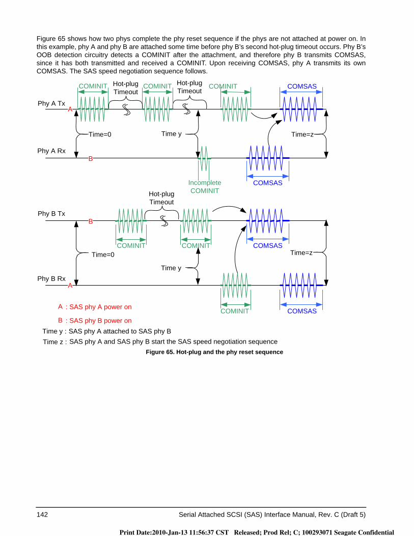
142 Serial Attached SCSI (SAS) Interface Manual, Rev. C (Draft 5)
Figure 65 shows how two phys complete the phy reset sequence if the phys are not attached at power on. In this example, phy A and phy B are attached some time before phy B’s second hot-plug timeout occurs. Phy B’s OOB detection circuitry detects a COMINIT after the attachment, and therefore phy B transmits COMSAS, since it has both transmitted and received a COMINIT. Upon receiving COMSAS, phy A transmits its own COMSAS. The SAS speed negotiation sequence follows.
Figure 65. Hot-plug and the phy reset sequence
COMSASIncomplete COMINIT
Time y :Time z :
SAS phy A attached to SAS phy BSAS phy A and SAS phy B start the SAS speed negotiation sequence
Phy A Rx
: SAS phy A power onA
B
: SAS phy B power onB
COMINITHot-plug Timeout
Hot-plug Timeout
Phy A TxA
COMSASCOMINITCOMINIT
COMINIT
Phy B RxA
COMSAS
COMSASCOMINITCOMINIT
Phy B TxB
Time y
Time yTime=0
Time=0
Time=z
Time=z
Hot-plug Timeout
Print Date:2010-Jan-13 11:56:37 CST Released; Prod Rel; C; 100293071 Seagate Confidential
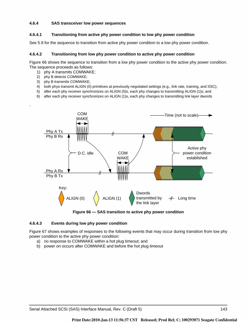
Serial Attached SCSI (SAS) Interface Manual, Rev. C (Draft 5) 143
4.6.4 SAS transceiver low power sequences
4.6.4.1 Transitioning from active phy power condition to low phy power condition
See 5.9 for the sequence to transition from active phy power condition to a low phy power condition.
4.6.4.2 Transitioning from low phy power condition to active phy power condition
Figure 66 shows the sequence to transition from a low phy power condition to the active phy power condition. The sequence proceeds as follows:
1) phy A transmits COMWAKE;2) phy B detects COMWAKE;3) phy B transmits COMWAKE;4) both phys transmit ALIGN (0) primitives at previously negotiated settings (e.g., link rate, training, and SSC);5) after each phy receiver synchronizes on ALIGN (0)s, each phy changes to transmitting ALIGN (1)s; and6) after each phy receiver synchronizes on ALIGN (1)s, each phy changes to transmitting link layer dwords
.
Figure 66 — SAS transition to active phy power condition
4.6.4.3 Events during low phy power condition
Figure 67 shows examples of responses to the following events that may occur during transition from low phy power condition to the active phy power condition:
a) no response to COMWAKE within a hot plug timeout; andb) power on occurs after COMWAKE and before the hot plug timeout
ALIGN (0) ALIGN (1)
Phy A RxPhy B Tx
Phy A TxPhy B Rx
Time (not to scale)
Dwords transmitted by the link layer
Long time
Key:
COMWAKE
D.C. idle COMWAKE
Active phy power condition
established
Print Date:2010-Jan-13 11:56:37 CST Released; Prod Rel; C; 100293071 Seagate Confidential
144 Serial Attached SCSI (SAS) Interface Manual, Rev. C (Draft 5)
.
Figure 67. Hot plug and low phy power condition
The sequence for a no response to COMWAKE within a hot plug timeout depicted in sequence 1 in figure 67proceeds as follows:
1) phy A transmits COMWAKE;2) phy A detects no COMWAKE within a hot plug timeout; and3) phy A transmits an OOB sequence.
The sequence for a power on occurs after COMWAKE and before the hot plug timeout depicted in sequence 2 in figure 67 proceeds as follows:
1) phy A transmits COMWAKE;2) phy A detects an OOB sequence within a hot plug timeout; and
phy A transmits an OOB sequence.
: SAS phy B power onB
Hot-plug Timeout
SAS phy A begins OOB sequence
COMWAKE
Sequence 1: No response to COMWAKE within a hot plug timeout
Phy A Tx/Phy B Rx
Phy A Rx/Phy B Tx
SAS phy B begins OOB sequence
COMWAKE
Sequence 2: power on occurs after COMWAKE and before the hot plug timeout
Phy A Tx/Phy B Rx
Phy A Rx/Phy B Tx
B
Time
Time
Print Date:2010-Jan-13 11:56:37 CST Released; Prod Rel; C; 100293071 Seagate Confidential
Serial Attached SCSI (SAS) Interface Manual, Rev. C (Draft 5) 145
4.7 DWS (dword synchronization)
The phy establishes the same dword boundaries at the receiver as at the attached transmitter by searching for control characters. A receiver in the phy monitors and decodes the incoming data stream and forces K28.5 characters into the first character position to effectively perform dword alignment. The receiver continues to reestablish dword alignment by forcing received K28.5 characters into the first character position until a valid primitive is detected. The resultant primitives, dwords and valid dword indicators (e.g., encoding error indica-tors) are processed to determine if the phy is in dword synchronization.
While dword synchronization is lost, the data stream received is invalid and dwords are not be passed to the link layer.
4.7.1 Acquiring DWS
To acquire DWS, three valid primitives starting with K28.5 must be received without any intervening invalid dwords. The drive continuously tries to acquire DWS. Only dwords received while in dword sync are pro-cessed.
4.7.2 Losing DWS
After DWS is acquired, when an invalid dword is detected, it requires two valid dwords to nullify its effect. When four invalid dwords are detected without nullification, dword synchronization is considered lost.
Print Date:2010-Jan-13 11:56:37 CST Released; Prod Rel; C; 100293071 Seagate Confidential
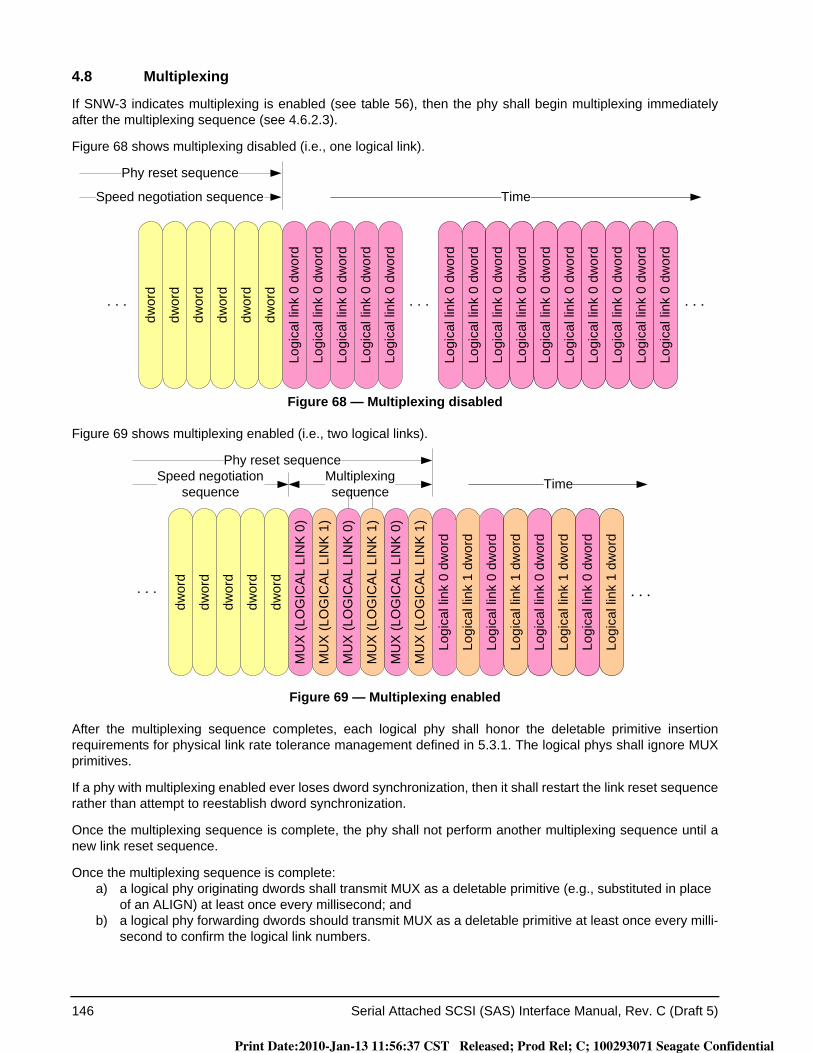
146 Serial Attached SCSI (SAS) Interface Manual, Rev. C (Draft 5)
4.8 Multiplexing
If SNW-3 indicates multiplexing is enabled (see table 56), then the phy shall begin multiplexing immediately after the multiplexing sequence (see 4.6.2.3).
Figure 68 shows multiplexing disabled (i.e., one logical link).
Figure 68 — Multiplexing disabled
Figure 69 shows multiplexing enabled (i.e., two logical links).
Figure 69 — Multiplexing enabled
After the multiplexing sequence completes, each logical phy shall honor the deletable primitive insertion requirements for physical link rate tolerance management defined in 5.3.1. The logical phys shall ignore MUX primitives.
If a phy with multiplexing enabled ever loses dword synchronization, then it shall restart the link reset sequence rather than attempt to reestablish dword synchronization.
Once the multiplexing sequence is complete, the phy shall not perform another multiplexing sequence until a new link reset sequence.
Once the multiplexing sequence is complete:a) a logical phy originating dwords shall transmit MUX as a deletable primitive (e.g., substituted in place
of an ALIGN) at least once every millisecond; andb) a logical phy forwarding dwords should transmit MUX as a deletable primitive at least once every milli-
second to confirm the logical link numbers.
Time
Logi
cal l
ink
0 dw
ord
Logi
cal l
ink
0 dw
ord
Logi
cal l
ink
0 dw
ord
Logi
cal l
ink
0 dw
ord
Logi
cal l
ink
0 dw
ord
Logi
cal l
ink
0 dw
ord
Logi
cal l
ink
0 dw
ord
Logi
cal l
ink
0 dw
ord
Logi
cal l
ink
0 dw
ord
Logi
cal l
ink
0 dw
ord
Logi
cal l
ink
0 dw
ord
Logi
cal l
ink
0 dw
ord
Logi
cal l
ink
0 dw
ord
dwor
d
dwor
d
dwor
dSpeed negotiation sequence
dwor
d
dwor
d
Logi
cal l
ink
0 dw
ord
Logi
cal l
ink
0 dw
ord
dwor
d
Phy reset sequence
Time
Logi
cal l
ink
0 dw
ord
Logi
cal l
ink
1 dw
ord
MU
X (L
OG
ICA
L LI
NK
0)
MU
X (L
OG
ICA
L LI
NK
1)
MU
X (L
OG
ICA
L LI
NK
0)
MU
X (L
OG
ICA
L LI
NK
1)
MU
X (L
OG
ICA
L LI
NK
0)
MU
X (L
OG
ICA
L LI
NK
1)
Logi
cal l
ink
0 dw
ord
Logi
cal l
ink
1 dw
ord
Logi
cal l
ink
0 dw
ord
Logi
cal l
ink
1 dw
ord
dwor
d
dwor
d
dwor
d
dwor
d
dwor
d
Speed negotiation sequence
Logi
cal l
ink
0 dw
ord
Logi
cal l
ink
1 dw
ord
Multiplexingsequence
Phy reset sequence
Print Date:2010-Jan-13 11:56:37 CST Released; Prod Rel; C; 100293071 Seagate Confidential
Serial Attached SCSI (SAS) Interface Manual, Rev. C (Draft 5) 147
Transmitting NOTIFY has higher priority than transmitting MUX.
Note. Periodic MUX transmission is for the convenience of logic analyzers and to provide additional assurance that the receiving phy is in agreement with the transmitting phy.
If a phy ever receives a MUX primitive that does not match the MUX primitive expected in that position (i.e., it receives MUX (LOGICAL LINK 1) on logical link 0 or receives MUX (LOGICAL LINK 0) on logical link 1), then it shall perform a link reset sequence.
4.9 Spin-up
The drive implements SAS power conditions. This states that the Power Condition mode page and START STOP UNIT command interact with the NOTIFY(ENABLE SPINUP) primitive to control temporary consumption of additional power as described below: (Reference SAS Spec 10.2.8)
The drive uses NOTIFY(ENABLE SPINUP) to:a. automatically spin–up after power on; andb. delay spin-up requested by START STOP UNIT commands.
The drive enters the Active Wait state, as defined in the SAS specification, after power-on. In this state the drive will spin up upon receiving NOTIFY (ENABLE SPINUP). If the drive receives a START/STOP UNIT com-mand with the Start bit set to zero at any time, it will spin down and enter the STOPPED state. In this state, NOTIFY (ENABLE SPINUP) is ignored. A START/STOP UNIT with the Start bit set to 1 will return the drive to the Active Wait state, where it will wait for a new NOTIFY (ENABLE SPINUP). If the START/STOP UNIT com-mand has the IMMED bit set to zero (meaning that the spinup must complete before returning status), the drive will wait up to five seconds for NOTIFY (ENABLE SPINUP). If not received within this time, the drive will termi-nate the command with a sense key of NOT READY and an ASC/ASCQ of NOTIFY (ENABLE SPINUP) REQUIRED (02/0411). The drive will remain in the Active Wait state so a subsequent NOTIFY (ENABLE SPINUP) will cause the drive to spin up.
Most host bus adapters and expanders will send NOTIFY to drives at intervals of a few seconds so timeouts should not occur. However, if the attached device must be given special instructions to send NOTIFY, a delay of at least 2 ms is recommended between the START/STOP unit command and the NOTIFY. This is because the drive must decode and begin processing the START UNIT command before it enters the Active Wait state and begins waiting for NOTIFY.
4.10 SP (phy layer) state machine
The SP state machine controls the phy reset sequence. Reference SPL for the definition of the SP state machine.
4.11 SP_DWS (phy layer dword synchronization) state machine
Each phy includes an SP_DWS state machine and an SP_DWS receiver. The SP_DWS state machine estab-lishes the same dword boundaries at the receiver as at the attached transmitter by searching for control char-acters. Reference SPL for the definition of the SP_DWS state machine.
Print Date:2010-Jan-13 11:56:37 CST Released; Prod Rel; C; 100293071 Seagate Confidential
148 Serial Attached SCSI (SAS) Interface Manual, Rev. C
5.0 Link layer
5.1 Link layer overview
The link layer defines primitives, address frames, and connections. The link layer interfaces to the port layer and the phy layer and perform the identification and hard reset sequences, connection management, and SSP, STP, and SMP specific frame transmission and reception.
5.2 Primitives
5.2.1 Primitives overview
Primitives are dwords whose first character is a K28.3, K28.5, or K28.6 control character. Primitives are not considered big-endian or little-endian; they are just interpreted as first, second, third, and last characters. Table 59 defines the primitive format. The drive ignores all primitives that do not start with K28.5.
Table 59. Primitive format
Character Description
First K28.5 control character (for primitives defined in this manual), or K28.3 control character (for primitives defined by SATA)
Second Constant data character.
Third Constant data character.
Last Constant data character.
Print Date:2010-Jan-13 11:56:37 CST Released; Prod Rel; C; 100293071 Seagate Confidential
Serial Attached SCSI (SAS) Interface Manual, Rev. C 149
5.2.2 Primitive summary
Table 60 defines the deletable primitives.
Table 60. Deletable primitives
Primitive Use aFrom b To b Primitive
sequence type cI E T I E T
ALIGN (0) All, SpNeg
I E T I E T SingleALIGN (1) SAS,
SpNeg
ALIGN (2)SAS
ALIGN (3)
MUX (LOGICAL LINK 0)SAS I E T I E T Single
MUX (LOGICAL LINK 1)
NOTIFY (ENABLE SPINUP)
SAS
I E T
SingleNOTIFY (POWER LOSS EXPECTED) I E T
NOTIFY (RESERVED 1) I E T
NOTIFY (RESERVED 2) I E T
a The Use column indicates when the primitive is used:a) All: SAS logical links and SATA physical links;b) SAS: SAS logical links, both outside connections or inside any type of connection;c) NoConn: SAS logical links, outside connections;d) Conn: SAS logical links, inside connections;e) STP: SAS logical links, inside STP connections; orf) SpNeg: SAS physical links, during speed negotiation.
b The From and To columns indicate the type of ports that originate each primitive or are the intended destinations of each primitive:a) I for SAS initiator ports;b) E for expander ports; andc) T for SAS target ports.
Expander ports are not considered originators of primitives that are being forwarded from expander port to expander port.
c The Primitive sequence type columns indicate whether the primitive is a single primitive sequence, a repeated primitive sequence, a continued primitive sequence, a triple primitive sequence, or a redundant primitive sequence (see 5.2.4).
Print Date:2010-Jan-13 11:56:37 CST Released; Prod Rel; C; 100293071 Seagate Confidential
150 Serial Attached SCSI (SAS) Interface Manual, Rev. C
Table 61 defines the primitives not specific to the type of connection.
Table 61. Primitives not specific to type of connection
Primitive Use aFrom b To b Primitive
sequence type dI E T I E T
AIP (NORMAL) NoConn E I E T Single
AIP (RESERVED 0) NoConn I E T Single
AIP (RESERVED 1) NoConn I E T Single
AIP (RESERVED 2) NoConn I E T Single
AIP (RESERVED WAITING ON PARTIAL) NoConn I E T Single
AIP (WAITING ON CONNECTION) NoConn E I E T Single
AIP (WAITING ON DEVICE) NoConn E I E T Single
AIP (WAITING ON PARTIAL) NoConn E I E T Single
BREAK All I E T I E T Redundant
BROADCAST (CHANGE) NoConn I E I E T Redundant
BROADCAST (SES) NoConn T I E T Redundant
BROADCAST (EXPANDER) NoConn E I E T Redundant
BROADCAST (ASYNCHRONOUS EVENT) NoConn T I Redundant
BROADCAST (RESERVED 3) NoConn I E T Redundant
BROADCAST (RESERVED 4) NoConn I E T Redundant
BROADCAST (RESERVED CHANGE 0) NoConn I E T Redundant
BROADCAST (RESERVED CHANGE 1) NoConn I E T Redundant
CLOSE (CLEAR AFFILIATION) STP I T Triple
CLOSE (NORMAL) Conn I T I T Triple
CLOSE (RESERVED 0) Conn I T Triple
CLOSE (RESERVED 1) Conn I T Triple
EOAF NoConn I E T I E T Single
ERROR All E I E T Single
HARD_RESET NoConn I E I E T Redundant
OPEN_ACCEPT NoConn I T I T Single
OPEN_REJECT (BAD DESTINATION) NoConn E I T Single
OPEN_REJECT (CONNECTION RATE NOT SUP-PORTED)
NoConn I E T I T Single
OPEN_REJECT (NO DESTINATION) NoConn E I T Single
OPEN_REJECT (PATHWAY BLOCKED) NoConn E I T Single
OPEN_REJECT (PROTOCOL NOT SUPPORTED) NoConn I T I T Single
Print Date:2010-Jan-13 11:56:37 CST Released; Prod Rel; C; 100293071 Seagate Confidential
Serial Attached SCSI (SAS) Interface Manual, Rev. C 151
OPEN_REJECT (RESERVED ABANDON 0) NoConn I T Single
OPEN_REJECT (RESERVED ABANDON 1) NoConn I T Single
OPEN_REJECT (RESERVED ABANDON 2) NoConn I T Single
OPEN_REJECT (RESERVED ABANDON 3) NoConn I T Single
OPEN_REJECT (RESERVED CONTINUE 0) NoConn I T Single
OPEN_REJECT (RESERVED CONTINUE 1) NoConn I T Single
OPEN_REJECT (RESERVED INITIALIZE 0) NoConn I T Single
OPEN_REJECT (RESERVED INITIALIZE 1) NoConn I T Single
OPEN_REJECT (RESERVED STOP 0) NoConn I T Single
OPEN_REJECT (RESERVED STOP 1) NoConn I T Single
OPEN_REJECT (RETRY) NoConn I T I T Single
OPEN_REJECT (STP RESOURCES BUSY) NoConn E T I Single
OPEN_REJECT (WRONG DESTINATION) NoConn I T I T Single
PS_ACK NoConn I E T I E T Redundant
PS_NAK NoConn I E T I E T Redundant
PS_REQ (PARTIAL) NoConn I E T I E T Redundant
PS_REQ (SLUMBER) NoConn I E T I E T Redundant
SOAF NoConn I E T I E T Single
SOAF NoConn I E T I E T Single
TRAIN SpNeg I E T I E T Redundant
a The Use column indicates when the primitive is used:a) NoConn: SAS physical links, outside connections;b) Conn: SAS physical links, inside connections;c) All: SAS physical links, both outside connections or inside any type of connection; ord) STP: SAS physical links, inside STP connections.
b The From and To columns indicate the type of ports that originate each primitive or are the intended destinations of each primitive:a) I for SAS initiator ports;b) E for expander ports; andc) T for SAS target ports.
c Expander ports are not considered originators of primitives that are passing through from expander port to expander port.
d The Primitive sequence type columns indicate whether the primitive is sent as a single primitive sequence, a repeated primitive sequence, a triple primitive sequence, or a redundant primitive sequence (see 5.2.4).
Table 61. Primitives not specific to type of connection
Primitive Use aFrom b To b Primitive
sequence type dI E T I E T
Print Date:2010-Jan-13 11:56:37 CST Released; Prod Rel; C; 100293071 Seagate Confidential
152 Serial Attached SCSI (SAS) Interface Manual, Rev. C
Table 62 defines the primitives used only inside SSP and SMP connections.
Table 62. Primitives used only inside SSP and SMP connections
Primitive Use aFrom b To b Primitive
sequence type dI E T I E T
ACK SSP I T I T Single
CREDIT_BLOCKED SSP I T I T Single
DONE (ACK/NAK TIMEOUT) SSP I T I T Single
DONE (CREDIT TIMEOUT) SSP I T I T Single
DONE (NORMAL) SSP I T I T Single
DONE (RESERVED 0) SSP I T Single
DONE (RESERVED 1) SSP I T Single
DONE (RESERVED TIMEOUT 0) SSP I T Single
DONE (RESERVED TIMEOUT 1) SSP I T Single
EOF SSP, SMP I T I T Single
NAK (CRC ERROR) SSP I T I T Single
NAK (RESERVED 0) SSP I T Single
NAK (RESERVED 1) SSP I T Single
NAK (RESERVED 2) SSP I T Single
RRDY (NORMAL) SSP I T I T Single
RRDY (RESERVED 0) SSP I T Single
RRDY (RESERVED 1) SSP I T Single
SOF SSP, SMP I T I T Single
a The Use column indicates when the primitive is used:a) SSP: SAS physical links, inside SSP connections; orb) SMP: SAS physical links, inside SMP connections.
b The From and To columns indicate the type of ports that originate each primitive or are the intended destinations of each primitive:a) I for SSP initiator ports and SMP initiator ports;b) E for expander ports; andc) T for SSP target ports and SMP target ports.
c Expander ports are not considered originators of primitives that are passing through from expander port to expander port.
d The Primitive sequence type columns indicate whether the primitive is sent as a single primitive sequence, a repeated primitive sequence, a triple primitive sequence, or a redundant primitive sequence (see 5.2.4).
Print Date:2010-Jan-13 11:56:37 CST Released; Prod Rel; C; 100293071 Seagate Confidential
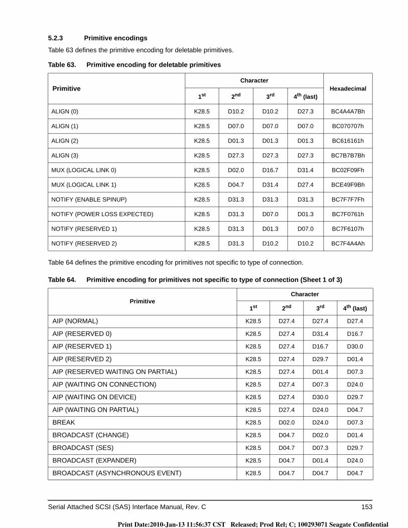
Serial Attached SCSI (SAS) Interface Manual, Rev. C 153
5.2.3 Primitive encodings
Table 63 defines the primitive encoding for deletable primitives.
Table 64 defines the primitive encoding for primitives not specific to type of connection.
Table 63. Primitive encoding for deletable primitives
PrimitiveCharacter
Hexadecimal1st 2nd 3rd 4th (last)
ALIGN (0) K28.5 D10.2 D10.2 D27.3 BC4A4A7Bh
ALIGN (1) K28.5 D07.0 D07.0 D07.0 BC070707h
ALIGN (2) K28.5 D01.3 D01.3 D01.3 BC616161h
ALIGN (3) K28.5 D27.3 D27.3 D27.3 BC7B7B7Bh
MUX (LOGICAL LINK 0) K28.5 D02.0 D16.7 D31.4 BC02F09Fh
MUX (LOGICAL LINK 1) K28.5 D04.7 D31.4 D27.4 BCE49F9Bh
NOTIFY (ENABLE SPINUP) K28.5 D31.3 D31.3 D31.3 BC7F7F7Fh
NOTIFY (POWER LOSS EXPECTED) K28.5 D31.3 D07.0 D01.3 BC7F0761h
NOTIFY (RESERVED 1) K28.5 D31.3 D01.3 D07.0 BC7F6107h
NOTIFY (RESERVED 2) K28.5 D31.3 D10.2 D10.2 BC7F4A4Ah
Table 64. Primitive encoding for primitives not specific to type of connection (Sheet 1 of 3)
PrimitiveCharacter
1st 2nd 3rd 4th (last)
AIP (NORMAL) K28.5 D27.4 D27.4 D27.4
AIP (RESERVED 0) K28.5 D27.4 D31.4 D16.7
AIP (RESERVED 1) K28.5 D27.4 D16.7 D30.0
AIP (RESERVED 2) K28.5 D27.4 D29.7 D01.4
AIP (RESERVED WAITING ON PARTIAL) K28.5 D27.4 D01.4 D07.3
AIP (WAITING ON CONNECTION) K28.5 D27.4 D07.3 D24.0
AIP (WAITING ON DEVICE) K28.5 D27.4 D30.0 D29.7
AIP (WAITING ON PARTIAL) K28.5 D27.4 D24.0 D04.7
BREAK K28.5 D02.0 D24.0 D07.3
BROADCAST (CHANGE) K28.5 D04.7 D02.0 D01.4
BROADCAST (SES) K28.5 D04.7 D07.3 D29.7
BROADCAST (EXPANDER) K28.5 D04.7 D01.4 D24.0
BROADCAST (ASYNCHRONOUS EVENT) K28.5 D04.7 D04.7 D04.7
Print Date:2010-Jan-13 11:56:37 CST Released; Prod Rel; C; 100293071 Seagate Confidential
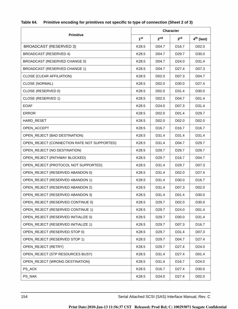
154 Serial Attached SCSI (SAS) Interface Manual, Rev. C
BROADCAST (RESERVED 3) K28.5 D04.7 D16.7 D02.0
BROADCAST (RESERVED 4) K28.5 D04.7 D29.7 D30.0
BROADCAST (RESERVED CHANGE 0) K28.5 D04.7 D24.0 D31.4
BROADCAST (RESERVED CHANGE 1) K28.5 D04.7 D27.4 D07.3
CLOSE (CLEAR AFFILIATION) K28.5 D02.0 D07.3 D04.7
CLOSE (NORMAL) K28.5 D02.0 D30.0 D27.4
CLOSE (RESERVED 0) K28.5 D02.0 D31.4 D30.0
CLOSE (RESERVED 1) K28.5 D02.0 D04.7 D01.4
EOAF K28.5 D24.0 D07.3 D31.4
ERROR K28.5 D02.0 D01.4 D29.7
HARD_RESET K28.5 D02.0 D02.0 D02.0
OPEN_ACCEPT K28.5 D16.7 D16.7 D16.7
OPEN_REJECT (BAD DESTINATION) K28.5 D31.4 D31.4 D31.4
OPEN_REJECT (CONNECTION RATE NOT SUPPORTED) K28.5 D31.4 D04.7 D29.7
OPEN_REJECT (NO DESTINATION) K28.5 D29.7 D29.7 D29.7
OPEN_REJECT (PATHWAY BLOCKED) K28.5 D29.7 D16.7 D04.7
OPEN_REJECT (PROTOCOL NOT SUPPORTED) K28.5 D31.4 D29.7 D07.3
OPEN_REJECT (RESERVED ABANDON 0) K28.5 D31.4 D02.0 D27.4
OPEN_REJECT (RESERVED ABANDON 1) K28.5 D31.4 D30.0 D16.7
OPEN_REJECT (RESERVED ABANDON 2) K28.5 D31.4 D07.3 D02.0
OPEN_REJECT (RESERVED ABANDON 3) K28.5 D31.4 D01.4 D30.0
OPEN_REJECT (RESERVED CONTINUE 0) K28.5 D29.7 D02.0 D30.0
OPEN_REJECT (RESERVED CONTINUE 1) K28.5 D29.7 D24.0 D01.4
OPEN_REJECT (RESERVED INITIALIZE 0) K28.5 D29.7 D30.0 D31.4
OPEN_REJECT (RESERVED INITIALIZE 1) K28.5 D29.7 D07.3 D16.7
OPEN_REJECT (RESERVED STOP 0) K28.5 D29.7 D31.4 D07.3
OPEN_REJECT (RESERVED STOP 1) K28.5 D29.7 D04.7 D27.4
OPEN_REJECT (RETRY) K28.5 D29.7 D27.4 D24.0
OPEN_REJECT (STP RESOURCES BUSY) K28.5 D31.4 D27.4 D01.4
OPEN_REJECT (WRONG DESTINATION) K28.5 D31.4 D16.7 D24.0
PS_ACK K28.5 D16.7 D27.4 D30.0
PS_NAK K28.5 D24.0 D27.4 D02.0
Table 64. Primitive encoding for primitives not specific to type of connection (Sheet 2 of 3)
PrimitiveCharacter
1st 2nd 3rd 4th (last)
Print Date:2010-Jan-13 11:56:37 CST Released; Prod Rel; C; 100293071 Seagate Confidential
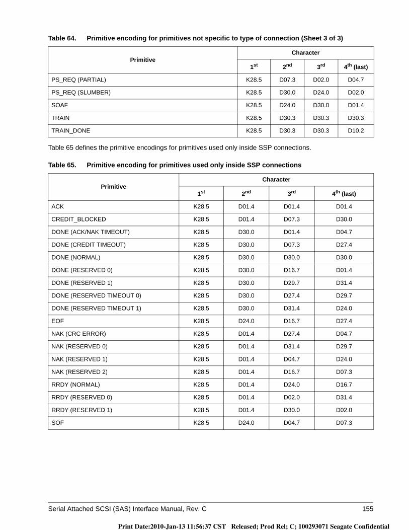
Serial Attached SCSI (SAS) Interface Manual, Rev. C 155
Table 65 defines the primitive encodings for primitives used only inside SSP connections.
PS_REQ (PARTIAL) K28.5 D07.3 D02.0 D04.7
PS_REQ (SLUMBER) K28.5 D30.0 D24.0 D02.0
SOAF K28.5 D24.0 D30.0 D01.4
TRAIN K28.5 D30.3 D30.3 D30.3
TRAIN_DONE K28.5 D30.3 D30.3 D10.2
Table 65. Primitive encoding for primitives used only inside SSP connections
PrimitiveCharacter
1st 2nd 3rd 4th (last)
ACK K28.5 D01.4 D01.4 D01.4
CREDIT_BLOCKED K28.5 D01.4 D07.3 D30.0
DONE (ACK/NAK TIMEOUT) K28.5 D30.0 D01.4 D04.7
DONE (CREDIT TIMEOUT) K28.5 D30.0 D07.3 D27.4
DONE (NORMAL) K28.5 D30.0 D30.0 D30.0
DONE (RESERVED 0) K28.5 D30.0 D16.7 D01.4
DONE (RESERVED 1) K28.5 D30.0 D29.7 D31.4
DONE (RESERVED TIMEOUT 0) K28.5 D30.0 D27.4 D29.7
DONE (RESERVED TIMEOUT 1) K28.5 D30.0 D31.4 D24.0
EOF K28.5 D24.0 D16.7 D27.4
NAK (CRC ERROR) K28.5 D01.4 D27.4 D04.7
NAK (RESERVED 0) K28.5 D01.4 D31.4 D29.7
NAK (RESERVED 1) K28.5 D01.4 D04.7 D24.0
NAK (RESERVED 2) K28.5 D01.4 D16.7 D07.3
RRDY (NORMAL) K28.5 D01.4 D24.0 D16.7
RRDY (RESERVED 0) K28.5 D01.4 D02.0 D31.4
RRDY (RESERVED 1) K28.5 D01.4 D30.0 D02.0
SOF K28.5 D24.0 D04.7 D07.3
Table 64. Primitive encoding for primitives not specific to type of connection (Sheet 3 of 3)
PrimitiveCharacter
1st 2nd 3rd 4th (last)
Print Date:2010-Jan-13 11:56:37 CST Released; Prod Rel; C; 100293071 Seagate Confidential
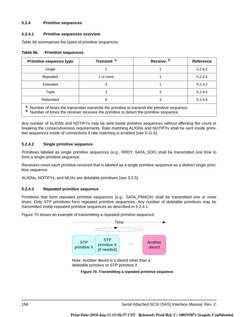
156 Serial Attached SCSI (SAS) Interface Manual, Rev. C
5.2.4 Primitive sequences
5.2.4.1 Primitive sequences overview
Table 66 summarizes the types of primitive sequences.
Any number of ALIGNs and NOTIFYs may be sent inside primitive sequences without affecting the count or breaking the consecutiveness requirements. Rate matching ALIGNs and NOTIFYs shall be sent inside primi-tive sequences inside of connections if rate matching is enabled (see 5.11.6).
5.2.4.2 Single primitive sequence
Primitives labeled as single primitive sequences (e.g., RRDY, SATA_SOF) shall be transmitted one time to form a single primitive sequence.
Receivers count each primitive received that is labeled as a single primitive sequence as a distinct single prim-itive sequence.
ALIGNs, NOTIFYs, and MUXs are deletable primitives (see 5.2.5).
5.2.4.3 Repeated primitive sequence
Primitives that form repeated primitive sequences (e.g., SATA_PMACK) shall be transmitted one or more times. Only STP primitives form repeated primitive sequences. Any number of deletable primitives may be transmitted inside repeated primitive sequences as described in 5.2.4.1.
Figure 70 shows an example of transmitting a repeated primitive sequence.
Figure 70. Transmitting a repeated primitive sequence
Table 66. Primitive sequences
Primitive sequence type Transmit a Receive b Reference
Single 1 1 5.2.4.2
Repeated 1 or more 1 5.2.4.5
Extended 3 1 5.2.4.2
Triple 3 3 5.2.4.5
Redundant 6 3 5.2.4.6
a Number of times the transmitter transmits the primitive to transmit the primitive sequence.b Number of times the receiver receives the primitive to detect the primitive sequence.
STP primitive X
STP primitive X(if needed)
Another dword
Time
Note: Another dword is a dword other than a deletable primitive or STP primitive X
Print Date:2010-Jan-13 11:56:37 CST Released; Prod Rel; C; 100293071 Seagate Confidential
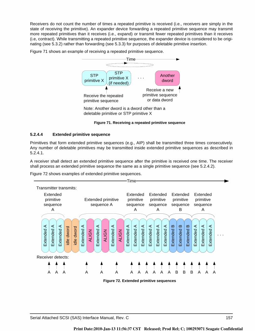
Serial Attached SCSI (SAS) Interface Manual, Rev. C 157
Receivers do not count the number of times a repeated primitive is received (i.e., receivers are simply in the state of receiving the primitive). An expander device forwarding a repeated primitive sequence may transmit more repeated primitives than it receives (i.e., expand) or transmit fewer repeated primitives than it receives (i.e, contract). While transmitting a repeated primitive sequence, the expander device is considered to be origi-nating (see 5.3.2) rather than forwarding (see 5.3.3) for purposes of deletable primitive insertion.
Figure 71 shows an example of receiving a repeated primitive sequence.
Figure 71. Receiving a repeated primitive sequence
5.2.4.4 Extended primitive sequence
Primitives that form extended primitive sequences (e.g., AIP) shall be transmitted three times consecutively. Any number of deletable primitives may be transmitted inside extended primitive sequences as described in 5.2.4.1.
A receiver shall detect an extended primitive sequence after the primitive is received one time. The receiver shall process an extended primitive sequence the same as a single primitive sequence (see 5.2.4.2).
Figure 72 shows examples of extended primitive sequences.
Figure 72. Extended primitive sequences
STP primitive X
STP primitive X(if needed)
Another dword
Time
Receive the repeated primitive sequence
Receive a new primitive sequence
or data dword
Note: Another dword is a dword other than a deletable primitive or STP primitive X
idle
dw
ord
Time
idle
dw
ord
ALI
GN
ALI
GN
Extended primitive sequence A
Ext
ende
d A
Ext
ende
d A
Ext
ende
d A
Ext
ende
d A
Ext
ende
d A
Ext
ende
d A
ALI
GN
Extended primitive
sequence A
Transmitter transmits:Extended primitive
sequence A
Ext
ende
d B
Ext
ende
d B
Ext
ende
d B
Extended primitive
sequence B
Extended primitive
sequence A
Ext
ende
d A
Ext
ende
d A
Ext
ende
d A
Ext
ende
d A
Ext
ende
d A
Ext
ende
d A
Receiver detects:
Extended primitive
sequence A
Ext
ende
d A
Ext
ende
d A
Ext
ende
d A
A A A A A A A A A A A AB B BAAA
Print Date:2010-Jan-13 11:56:37 CST Released; Prod Rel; C; 100293071 Seagate Confidential
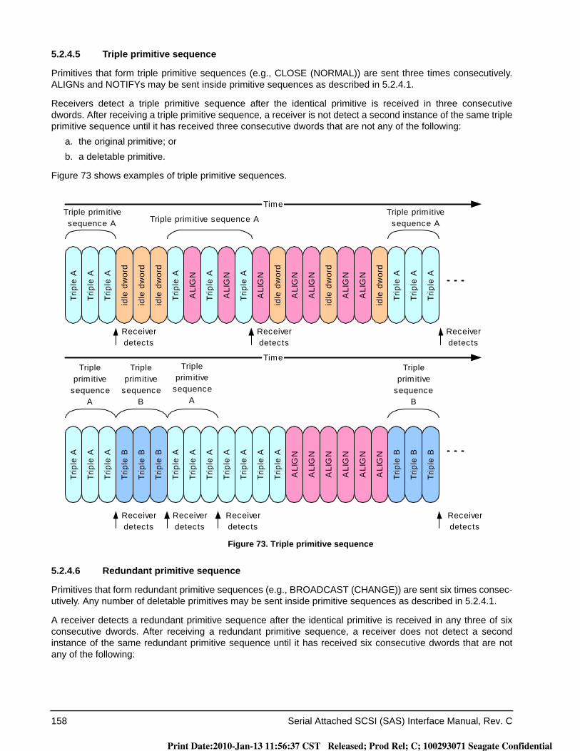
158 Serial Attached SCSI (SAS) Interface Manual, Rev. C
5.2.4.5 Triple primitive sequence
Primitives that form triple primitive sequences (e.g., CLOSE (NORMAL)) are sent three times consecutively. ALIGNs and NOTIFYs may be sent inside primitive sequences as described in 5.2.4.1.
Receivers detect a triple primitive sequence after the identical primitive is received in three consecutive dwords. After receiving a triple primitive sequence, a receiver is not detect a second instance of the same triple primitive sequence until it has received three consecutive dwords that are not any of the following:
a. the original primitive; orb. a deletable primitive.
Figure 73 shows examples of triple primitive sequences.
Figure 73. Triple primitive sequence
5.2.4.6 Redundant primitive sequence
Primitives that form redundant primitive sequences (e.g., BROADCAST (CHANGE)) are sent six times consec-utively. Any number of deletable primitives may be sent inside primitive sequences as described in 5.2.4.1.
A receiver detects a redundant primitive sequence after the identical primitive is received in any three of six consecutive dwords. After receiving a redundant primitive sequence, a receiver does not detect a second instance of the same redundant primitive sequence until it has received six consecutive dwords that are not any of the following:
idle
dw
ord
Time
idle
dw
ord
idle
dw
ord
ALI
GN
Tripleprimitive
sequenceA
Triple primitive sequence A
Trip
le A
Trip
le A
Trip
le A
Trip
le A
Trip
le A
Trip
le A
Trip
le B
Trip
le B
Trip
le B
Trip
le A
Trip
le A
Trip
le A
Trip
le A
Trip
le A
Trip
le A
ALI
GN
Time
Triple primitivesequence A
Tripleprimitive
sequenceB
Tripleprimitive
sequenceA
Receiverdetects
Receiverdetects
Receiverdetects
ALI
GN
idle
dw
ord
ALI
GN
ALI
GN
idle
dw
ord
ALI
GN
ALI
GN
idle
dw
ord
Trip
le A
Trip
le A
Trip
le A
Triple primitivesequence A
Receiverdetects
Receiverdetects
Trip
le B
Trip
le B
Trip
le B
Tripleprimitive
sequenceB
ALI
GN
ALI
GN
ALI
GN
ALI
GN
ALI
GN
ALI
GN
Receiverdetects
Trip
le A
Trip
le A
Trip
le A
Trip
le A
Receiverdetects
Print Date:2010-Jan-13 11:56:37 CST Released; Prod Rel; C; 100293071 Seagate Confidential
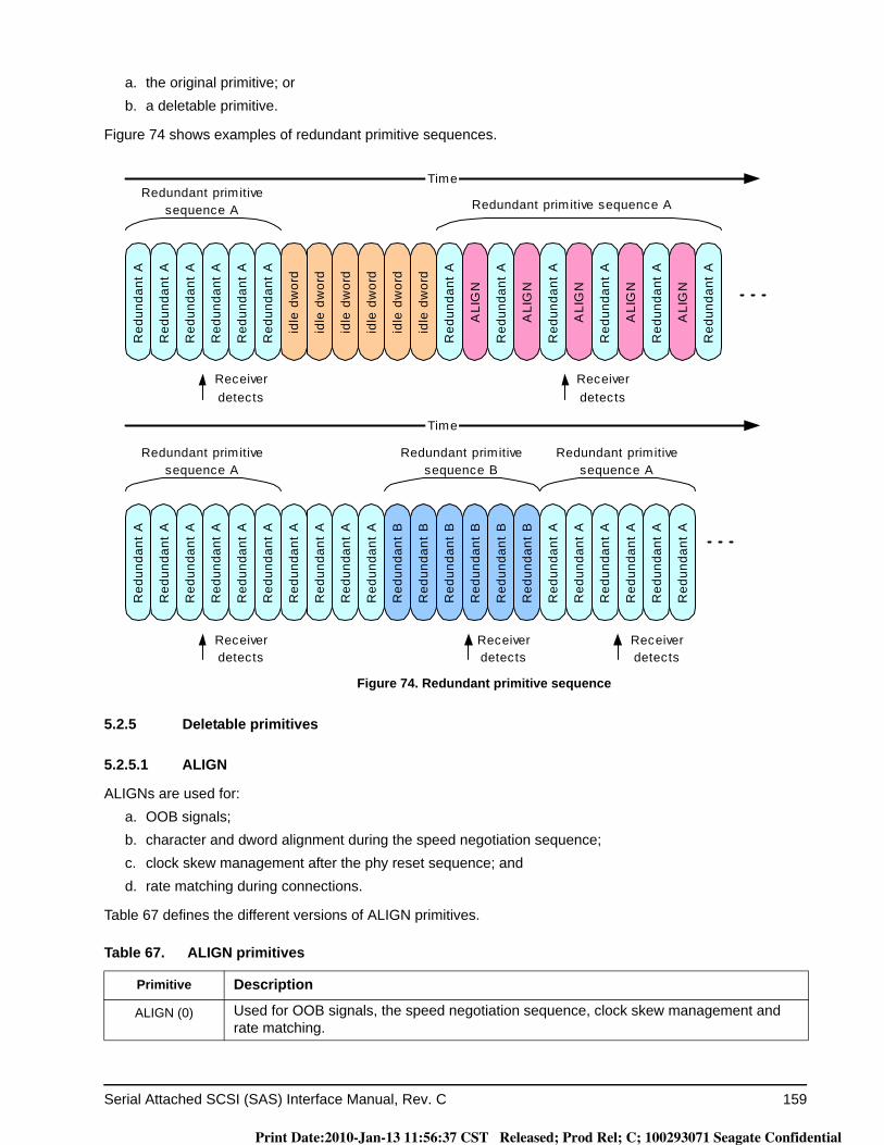
Serial Attached SCSI (SAS) Interface Manual, Rev. C 159
a. the original primitive; orb. a deletable primitive.
Figure 74 shows examples of redundant primitive sequences.
Figure 74. Redundant primitive sequence
5.2.5 Deletable primitives
5.2.5.1 ALIGN
ALIGNs are used for:a. OOB signals;b. character and dword alignment during the speed negotiation sequence;c. clock skew management after the phy reset sequence; andd. rate matching during connections.
Table 67 defines the different versions of ALIGN primitives.
Table 67. ALIGN primitives
Primitive Description
ALIGN (0) Used for OOB signals, the speed negotiation sequence, clock skew management and rate matching.
idle
dw
ord
Time
idle
dw
ord
idle
dw
ord
idle
dw
ord
idle
dw
ord
idle
dw
ord
ALI
GN
ALI
GN
ALI
GN
Redundant primitivesequence A
Redundant primitive sequence A
Red
unda
nt A
Red
unda
nt A
Red
unda
nt A
Red
unda
nt A
Red
unda
nt A
Red
unda
nt A
Red
unda
nt A
Red
unda
nt A
Red
unda
nt A
Red
unda
nt A
Red
unda
nt A
Red
unda
nt A
Red
unda
nt B
Red
unda
nt B
Red
unda
nt B
Red
unda
nt B
Red
unda
nt B
Red
unda
nt B
Red
unda
nt A
Red
unda
nt A
Red
unda
nt A
Red
unda
nt A
Red
unda
nt A
Red
unda
nt A
Red
unda
nt A
Red
unda
nt A
Red
unda
nt A
Red
unda
nt A
Red
unda
nt A
Red
unda
nt A
ALI
GN
ALI
GN
Time
Redundant primitivesequence A
Redundant primitivesequence B
Redundant primitivesequence A
Receiverdetects
Receiverdetects
Receiverdetects
Receiverdetects
Receiverdetects
Red
unda
nt A
Red
unda
nt A
Red
unda
nt A
Red
unda
nt A
Print Date:2010-Jan-13 11:56:37 CST Released; Prod Rel; C; 100293071 Seagate Confidential
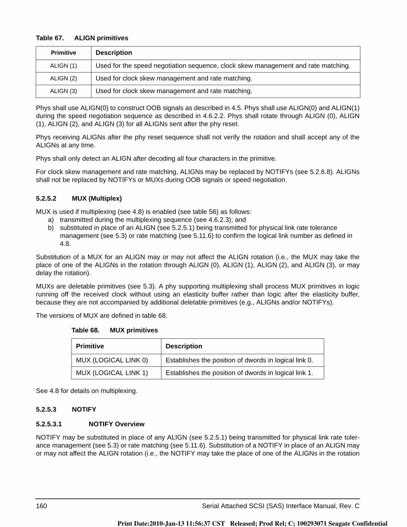
160 Serial Attached SCSI (SAS) Interface Manual, Rev. C
Phys shall use ALIGN(0) to construct OOB signals as described in 4.5. Phys shall use ALIGN(0) and ALIGN(1) during the speed negotiation sequence as described in 4.6.2.2. Phys shall rotate through ALIGN (0), ALIGN (1), ALIGN (2), and ALIGN (3) for all ALIGNs sent after the phy reset.
Phys receiving ALIGNs after the phy reset sequence shall not verify the rotation and shall accept any of the ALIGNs at any time.
Phys shall only detect an ALIGN after decoding all four characters in the primitive.
For clock skew management and rate matching, ALIGNs may be replaced by NOTIFYs (see 5.2.6.8). ALIGNs shall not be replaced by NOTIFYs or MUXs during OOB signals or speed negotiation.
5.2.5.2 MUX (Multiplex)
MUX is used if multiplexing (see 4.8) is enabled (see table 56) as follows:a) transmitted during the multiplexing sequence (see 4.6.2.3); andb) substituted in place of an ALIGN (see 5.2.5.1) being transmitted for physical link rate tolerance
management (see 5.3) or rate matching (see 5.11.6) to confirm the logical link number as defined in 4.8.
Substitution of a MUX for an ALIGN may or may not affect the ALIGN rotation (i.e., the MUX may take the place of one of the ALIGNs in the rotation through ALIGN (0), ALIGN (1), ALIGN (2), and ALIGN (3), or may delay the rotation).
MUXs are deletable primitives (see 5.3). A phy supporting multiplexing shall process MUX primitives in logic running off the received clock without using an elasticity buffer rather than logic after the elasticity buffer, because they are not accompanied by additional deletable primitives (e.g., ALIGNs and/or NOTIFYs).
The versions of MUX are defined in table 68.
See 4.8 for details on multiplexing.
5.2.5.3 NOTIFY
5.2.5.3.1 NOTIFY Overview
NOTIFY may be substituted in place of any ALIGN (see 5.2.5.1) being transmitted for physical link rate toler-ance management (see 5.3) or rate matching (see 5.11.6). Substitution of a NOTIFY in place of an ALIGN may or may not affect the ALIGN rotation (i.e., the NOTIFY may take the place of one of the ALIGNs in the rotation
ALIGN (1) Used for the speed negotiation sequence, clock skew management and rate matching.
ALIGN (2) Used for clock skew management and rate matching.
ALIGN (3) Used for clock skew management and rate matching.
Table 68. MUX primitives
Primitive Description
MUX (LOGICAL LINK 0) Establishes the position of dwords in logical link 0.
MUX (LOGICAL LINK 1) Establishes the position of dwords in logical link 1.
Table 67. ALIGN primitives
Primitive Description
Print Date:2010-Jan-13 11:56:37 CST Released; Prod Rel; C; 100293071 Seagate Confidential
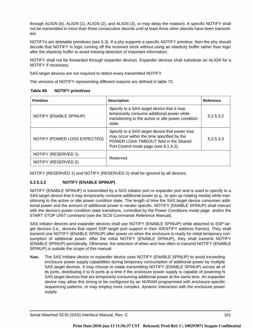
Serial Attached SCSI (SAS) Interface Manual, Rev. C 161
through ALIGN (0), ALIGN (1), ALIGN (2), and ALIGN (3), or may delay the rotation). A specific NOTIFY shall not be transmitted in more than three consecutive dwords until at least three other dwords have been transmit-ted.
NOTIFYs are deletable primitives (see 5.3). If a phy supports a specific NOTIFY primitive, then the phy should decode that NOTIFY in logic running off the received clock without using an elasticity buffer rather than logic after the elasticity buffer to avoid missing detection of important information.
NOTIFY shall not be forwarded through expander devices. Expander devices shall substitute an ALIGN for a NOTIFY if necessary.
SAS target devices are not required to detect every transmitted NOTIFY.
The versions of NOTIFY representing different reasons are defined in table 73.
NOTIFY (RESERVED 1) and NOTIFY (RESERVED 2) shall be ignored by all devices.
5.2.5.3.2 NOTIFY (ENABLE SPINUP)
NOTIFY (ENABLE SPINUP) is transmitted by a SAS initiator port or expander port and is used to specify to a SAS target device that it may temporarily consume additional power (e.g., to spin up rotating media) while tran-sitioning to the active or idle power condition state. The length of time the SAS target device consumes addi-tional power and the amount of additional power is vendor specific. NOTIFY (ENABLE SPINUP) shall interact with the device's power condition state transitions, controlled by the Power Conditions mode page and/or the START STOP UNIT command (see the SCSI Commands Reference Manual).
SAS initiator devices and expander devices shall use NOTIFY (ENABLE SPINUP) while attached to SSP tar-get devices (i.e., devices that report SSP target port support in their IDENTIFY address frames). They shall transmit one NOTIFY (ENABLE SPINUP) after power on when the enclosure is ready for initial temporary con-sumption of additional power. After the initial NOTIFY (ENABLE SPINUP), they shall transmit NOTIFY (ENABLE SPINUP) periodically. Otherwise, the selection of when and how often to transmit NOTIFY (ENABLE SPINUP) is outside the scope of this manual.
Note. The SAS initiator device or expander device uses NOTIFY (ENABLE SPINUP) to avoid exceeding enclosure power supply capabilities during temporary consumption of additional power by multiple SAS target devices. It may choose to rotate transmitting NOTIFY (ENABLE SPINUP) across all of its ports, distributing it to N ports at a time if the enclosure power supply is capable of powering N SAS target devices that are temporarily consuming additional power at the same time. An expander device may allow this timing to be configured by an NVRAM programmed with enclosure-specific sequencing patterns, or may employ more complex, dynamic interaction with the enclosure power supply.
Table 69. NOTIFY primitives
Primitive Description Reference
NOTIFY (ENABLE SPINUP)
Specify to a SAS target device that it may temporarily consume additional power while transitioning to the active or idle power condition state.
5.2.5.3.2
NOTIFY (POWER LOSS EXPECTED)
Specify to a SAS target device that power loss may occur within the time specified by the POWER LOAA TIMEOUT field in the Shared Port Control mode page (see 8.1.4.2).
5.2.5.3.3
NOTIFY (RESERVED 1)Reserved.
NOTIFY (RESERVED 2)
Print Date:2010-Jan-13 11:56:37 CST Released; Prod Rel; C; 100293071 Seagate Confidential
162 Serial Attached SCSI (SAS) Interface Manual, Rev. C
Note. NOTIFY (ENABLE SPINUP) should be transmitted as frequently as possible to avoid incurring SCSI application layer timeouts.
A SAS target device with multiple SAS target ports shall equivalently process a NOTIFY (ENABLE SPINUP) received by any of its SAS target ports (e.g., if a SAS target device contains two SSP target ports A and B, powers on in the Stopped state, and receives a START STOP UNIT command with the START bit set to one through SSP target port A, then a NOTIFY (ENABLE SPINUP) received on SSP target port B allows the SAS target device to temporarily consume additional power (see SAS-2).
5.2.5.3.3 NOTIFY (POWER LOSS EXPECTED)
NOTIFY (POWER LOSS EXPECTED) is transmitted by a SAS initiator port or expander port and is used to specify to a SAS target device that power loss may occur within the time specified in the POWER LOSS TIME-OUT field in the Shared Port Control mode page (see the SCSI Commands Reference Manual).
NOTIFY (POWER LOSS EXPECTED) shall be transmitted at least three times by the SAS initiator port or expander port.
If a SAS target device supports NOTIFY (POWER LOSS EXPECTED) and receives NOTIFY (POWER LOSS EXPECTED) on an SSP target port, then:
a) the device server for each logical unit to which the SSP target port has access shall:1)stop writing data to the media as soon as possible without creating read errors for future reads (e.g.,
on a direct-access block device, a physical block boundary is reached);2)clear all task sets as defined in SAM-4; and3)establish a unit attention condition for the initiator port associated with every I_T nexus as defined in
SAM-4 (e.g., with the additional sense code set to COMMANDS CLEARED BY POWER LOSS NOTIFICATION);
and
b) the SAS target device shall:A) on each phy that receives NOTIFY (POWER LOSS EXPECTED), if there is an SSP connection,
then transmit a BREAK on that connection; andB) on each phy that does not receive NOTIFY (POWER LOSS EXPECTED), if there is an SSP
connection, then transmit a BREAK or a CLOSE on that connection.
If the SAS target device receives any frames after receiving NOTIFY (POWER LOSS EXPECTED) before a connection is closed, then it should discard the received frames.
The SCSI application layer that receives a Power Loss Expected event shall:a) start the power loss timer;b) send OPEN_REJECT (RETRY) in response to all SSP connection requests;c) abort any commands received before connections are closed; andd) if the power loss timeout timer expires, then the SCSI application layer shall establish a unit attention
condition for each I_T nexus with the additional sense code set to POWER FAIL EVENT COMMANDS CLEARED and allow SSP connection requests.
After power on, the power loss timeout timer shall be initialized and stopped until a NOTIFY (POWER LOSS EXPECTED) is received.
Print Date:2010-Jan-13 11:56:37 CST Released; Prod Rel; C; 100293071 Seagate Confidential
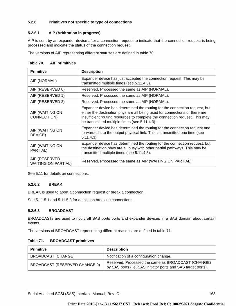
Serial Attached SCSI (SAS) Interface Manual, Rev. C 163
5.2.6 Primitives not specific to type of connections
5.2.6.1 AIP (Arbitration in progress)
AIP is sent by an expander device after a connection request to indicate that the connection request is being processed and indicate the status of the connection request.
The versions of AIP representing different statuses are defined in table 70.
See 5.11 for details on connections.
5.2.6.2 BREAK
BREAK is used to abort a connection request or break a connection.
See 5.11.5.1 and 5.11.5.3 for details on breaking connections.
5.2.6.3 BROADCAST
BROADCASTs are used to notify all SAS ports ports and expander devices in a SAS domain about certain events.
The versions of BROADCAST representing different reasons are defined in table 71.
Table 70. AIP primitives
Primitive Description
AIP (NORMAL) Expander device has just accepted the connection request. This may be transmitted multiple times (see 5.11.4.3).
AIP (RESERVED 0) Reserved. Processed the same as AIP (NORMAL).AIP (RESERVED 1) Reserved. Processed the same as AIP (NORMAL).AIP (RESERVED 2) Reserved. Processed the same as AIP (NORMAL).
AIP (WAITING ON CONNECTION)
Expander device has determined the routing for the connection request, but either the destination phys are all being used for connections or there are insufficient routing resources to complete the connection request. This may be transmitted multiple times (see 5.11.4.3).
AIP (WAITING ON DEVICE)
Expander device has determined the routing for the connection request and forwarded it to the output physical link. This is transmitted one time (see 5.11.4.3).
AIP (WAITING ON PARTIAL)
Expander device has determined the routing for the connection request, but the destination phys are all busy with other partial pathways. This may be transmitted multiple times (see 5.11.4.3).
AIP (RESERVED WAITING ON PARTIAL) Reserved. Processed the same as AIP (WAITING ON PARTIAL).
Table 71. BROADCAST primitives
Primitive Description
BROADCAST (CHANGE) Notification of a configuration change.
BROADCAST (RESERVED CHANGE 0) Reserved. Processed the same as BROADCAST (CHANGE) by SAS ports (i.e, SAS initiator ports and SAS target ports).
Print Date:2010-Jan-13 11:56:37 CST Released; Prod Rel; C; 100293071 Seagate Confidential
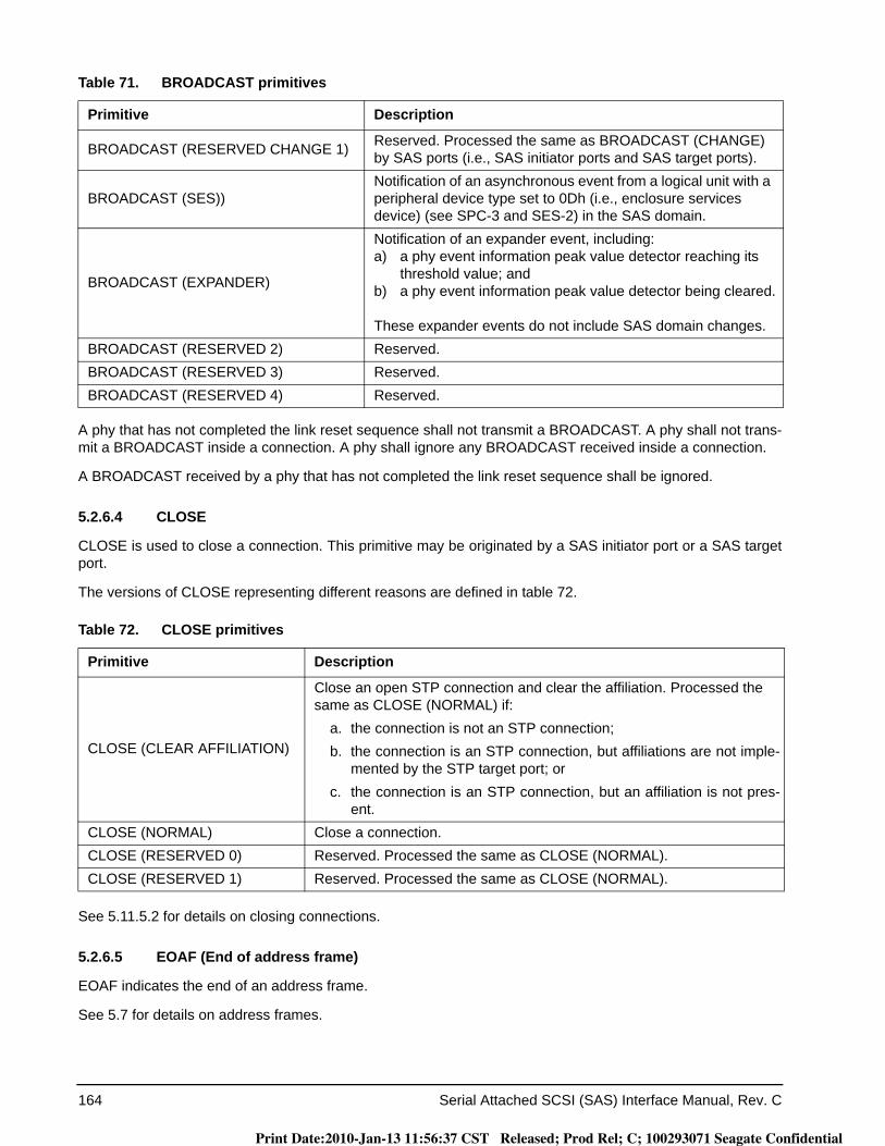
164 Serial Attached SCSI (SAS) Interface Manual, Rev. C
A phy that has not completed the link reset sequence shall not transmit a BROADCAST. A phy shall not trans-mit a BROADCAST inside a connection. A phy shall ignore any BROADCAST received inside a connection.
A BROADCAST received by a phy that has not completed the link reset sequence shall be ignored.
5.2.6.4 CLOSE
CLOSE is used to close a connection. This primitive may be originated by a SAS initiator port or a SAS target port.
The versions of CLOSE representing different reasons are defined in table 72.
See 5.11.5.2 for details on closing connections.
5.2.6.5 EOAF (End of address frame)
EOAF indicates the end of an address frame.
See 5.7 for details on address frames.
BROADCAST (RESERVED CHANGE 1) Reserved. Processed the same as BROADCAST (CHANGE) by SAS ports (i.e., SAS initiator ports and SAS target ports).
BROADCAST (SES))Notification of an asynchronous event from a logical unit with a peripheral device type set to 0Dh (i.e., enclosure services device) (see SPC-3 and SES-2) in the SAS domain.
BROADCAST (EXPANDER)
Notification of an expander event, including:a) a phy event information peak value detector reaching its
threshold value; andb) a phy event information peak value detector being cleared.
These expander events do not include SAS domain changes.BROADCAST (RESERVED 2) Reserved.BROADCAST (RESERVED 3) Reserved.BROADCAST (RESERVED 4) Reserved.
Table 72. CLOSE primitives
Primitive Description
CLOSE (CLEAR AFFILIATION)
Close an open STP connection and clear the affiliation. Processed the same as CLOSE (NORMAL) if:
a. the connection is not an STP connection;b. the connection is an STP connection, but affiliations are not imple-
mented by the STP target port; orc. the connection is an STP connection, but an affiliation is not pres-
ent.CLOSE (NORMAL) Close a connection.CLOSE (RESERVED 0) Reserved. Processed the same as CLOSE (NORMAL).CLOSE (RESERVED 1) Reserved. Processed the same as CLOSE (NORMAL).
Table 71. BROADCAST primitives
Primitive Description
Print Date:2010-Jan-13 11:56:37 CST Released; Prod Rel; C; 100293071 Seagate Confidential
Serial Attached SCSI (SAS) Interface Manual, Rev. C 165
5.2.6.6 ERROR
An expander device substitutes the ERROR primitive for an invalid dword when it is forwarding dwords from a SAS physical link.
5.2.6.7 HARD_RESET
HARD_RESET is used to force a phy to generate a hard reset (see 2.3.2) to its port. This primitive is only valid after the phy reset sequence without an intervening identification sequence (see 2.3) and shall be ignored at other times.
5.2.6.8 NOTIFY
NOTIFY may be transmitted in place of any ALIGN being transmitted for clock skew management (see 5.3) or rate matching (see 5.11.6). Substitution of a NOTIFY may or may not affect the ALIGN sequencing (i.e., the NOTIFY may take the place of one of the ALIGNs in the rotation through ALIGN (0), ALIGN (1), ALIGN (2), or ALIGN (3) or it may delay the rotation). A specific NOTIFY can not be transmitted a second time until at least three ALIGNs or different NOTIFYs have been transmitted.
NOTIFY is not forwarded through expander devices. Expander devices substitute an ALIGN for a NOTIFY.
The versions of NOTIFY representing different reasons are defined in table 73.
NOTIFY (ENABLE SPINUP) is transmitted by a SAS initiator port for point to point configurations or expander port and is used to signal the drive when to spinup. The drive’s reaction to a NOTIFY (ENABLE SPINUP) is controlled by the Power Conditions mode page and/or the START STOP UNIT command.
NOTIFY (ENABLE SPINUP) is transmitted after power on when the enclosure is ready for initial spin-up. After the initial NOTIFY (ENABLE SPINUP), is periodically transmitted.
I_T nexus loss, logical unit reset, and hard reset do not cause the drive to spinup automatically on receipt of NOTIFY (ENABLE SPINUP).
The drive treats a NOTIFY (ENABLE SPINUP) received on either port as signal to proceed with spinup as selected by the Power Conditions mode page and/or the START STOP UNIT command
NOTIFY (RESERVED 0), NOTIFY (RESERVED 1), and NOTIFY (RESERVED 2) are ignored by the drive.
NOTIFY (POWER LOSS EXPECTED) is transmitted by a SAS initiator port or expander port and is used to specify to a SAS target device that power loss may occur within the time specified in the POWER LOSS TIMEOUTfield in the Protocol-Specific Logical Unit mode page (see 8.1.4.3).
NOTIFY (POWER LOSS EXPECTED) shall be transmitted at least three times by the SAS initiator port or expander port.
If a SAS target device supports NOTIFY (POWER LOSS EXPECTED) and receives NOTIFY (POWER LOSS EXPECTED) on an SSP target port, then the device server for each logical unit to which the SSP target port has access shall, within 1 ms:
Table 73. NOTIFY primitives
Primitive Description
NOTIFY (ENABLE SPINUP) Specify to an SAS target device that it may temporarily consume additional power while transitioning into the active or idle power condition state.
NOTIFY (RESERVED 0) Reserved.NOTIFY (RESERVED 1) Reserved.NOTIFY (RESERVED 2) Reserved.
Print Date:2010-Jan-13 11:56:37 CST Released; Prod Rel; C; 100293071 Seagate Confidential
166 Serial Attached SCSI (SAS) Interface Manual, Rev. C
1. stop writing data to the media on a block boundary (e.g., all write activity shall continue until a block boundary is reached then all writing shall stop); and
2. clear all task sets (i.e., the device server acts as if it has received a CLEAR TASK SET task manage-ment function (see SAM-4) for each task set); and
3. establish a unit attention condition for the initiator port associated with every I_T nexus with the addi-tional sense code set to COMMANDS CLEARED BY POWER LOSS NOTIFICATION.
If a SAS target device supports NOTIFY (POWER LOSS EXPECTED) and receives NOTIFY (POWER LOSS EXPECTED) on an SSP target port, then each SAS phy within the target device shall:
1. if there is an SSP connection, then transmit a BREAK on that connection; and2. respond to SSP connection requests with OPEN_REJECT (RETRY) until the power loss timeout timer
expires or power is lost.
If any frames are received by the SAS target device after receiving NOTIFY (POWER LOSS EXPECTED) before a connection is closed, then the SAS target device shall discard the received frames.
After power on, the power loss timeout timer shall be initialized and stopped until a NOTIFY (POWER LOSS EXPECTED) is received.
5.2.6.9 OPEN_ACCEPT
OPEN_ACCEPT indicates the acceptance of a connection request.
See 5.11 for details on connection requests.
5.2.6.10 OPEN_REJECT
OPEN_REJECT indicates that a connection request has been rejected and indicates the reason for the rejec-tion. The result of some OPEN_REJECTs is to abandon (i.e., not retry) the connection request and the result of other OPEN_REJECTs is to retry the connection request.
All of the OPEN_REJECT versions defined in table 74 result in the originating device abandoning the connec-tion request.
Table 74. Abandon-class OPEN_REJECT primitives
Primitive Originator Description
OPEN_REJECT (BAD DESTINA-TION) Expander phy
An expander device receives a request in which the destination SAS address equals the source SAS address, or a connection request arrives through an expander phy using the direct routing or table routing method and the expander device determines the connection request would have to be routed to the same expander port as the expander port through which the connection request arrived.
Print Date:2010-Jan-13 11:56:37 CST Released; Prod Rel; C; 100293071 Seagate Confidential
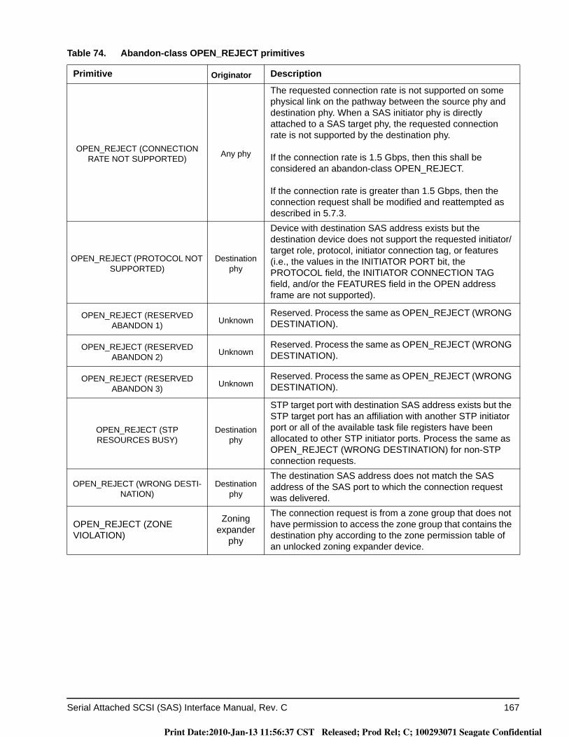
Serial Attached SCSI (SAS) Interface Manual, Rev. C 167
OPEN_REJECT (CONNECTION RATE NOT SUPPORTED) Any phy
The requested connection rate is not supported on some physical link on the pathway between the source phy and destination phy. When a SAS initiator phy is directly attached to a SAS target phy, the requested connection rate is not supported by the destination phy.
If the connection rate is 1.5 Gbps, then this shall be considered an abandon-class OPEN_REJECT.
If the connection rate is greater than 1.5 Gbps, then the connection request shall be modified and reattempted as described in 5.7.3.
OPEN_REJECT (PROTOCOL NOT SUPPORTED)
Destination phy
Device with destination SAS address exists but the destination device does not support the requested initiator/target role, protocol, initiator connection tag, or features (i.e., the values in the INITIATOR PORT bit, the PROTOCOL field, the INITIATOR CONNECTION TAG field, and/or the FEATURES field in the OPEN address frame are not supported).
OPEN_REJECT (RESERVED ABANDON 1) Unknown
Reserved. Process the same as OPEN_REJECT (WRONG DESTINATION).
OPEN_REJECT (RESERVED ABANDON 2) Unknown
Reserved. Process the same as OPEN_REJECT (WRONG DESTINATION).
OPEN_REJECT (RESERVED ABANDON 3) Unknown
Reserved. Process the same as OPEN_REJECT (WRONG DESTINATION).
OPEN_REJECT (STP RESOURCES BUSY)
Destination phy
STP target port with destination SAS address exists but the STP target port has an affiliation with another STP initiator port or all of the available task file registers have been allocated to other STP initiator ports. Process the same as OPEN_REJECT (WRONG DESTINATION) for non-STP connection requests.
OPEN_REJECT (WRONG DESTI-NATION)
Destination phy
The destination SAS address does not match the SAS address of the SAS port to which the connection request was delivered.
OPEN_REJECT (ZONE VIOLATION)
Zoning expander
phy
The connection request is from a zone group that does not have permission to access the zone group that contains the destination phy according to the zone permission table of an unlocked zoning expander device.
Table 74. Abandon-class OPEN_REJECT primitives
Primitive Originator Description
Print Date:2010-Jan-13 11:56:37 CST Released; Prod Rel; C; 100293071 Seagate Confidential
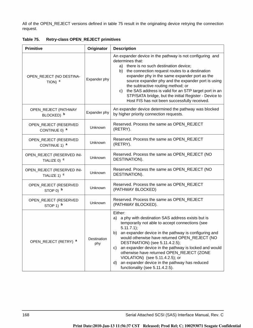
168 Serial Attached SCSI (SAS) Interface Manual, Rev. C
All of the OPEN_REJECT versions defined in table 75 result in the originating device retrying the connection request.
Table 75. Retry-class OPEN_REJECT primitives
Primitive Originator Description
OPEN_REJECT (NO DESTINA-TION) c
Expander phy
An expander device in the pathway is not configuring and determines that:
a) there is no such destination device;b) the connection request routes to a destination
expander phy in the same expander port as the source expander phy and the expander port is using the subtractive routing method; or
c) the SAS address is valid for an STP target port in an STP/SATA bridge, but the initial Register - Device to Host FIS has not been successfully received.
OPEN_REJECT (PATHWAY BLOCKED) b
Expander phyAn expander device determined the pathway was blocked by higher priority connection requests.
OPEN_REJECT (RESERVED CONTINUE 0) a
UnknownReserved. Process the same as OPEN_REJECT (RETRY).
OPEN_REJECT (RESERVED CONTINUE 1) a
UnknownReserved. Process the same as OPEN_REJECT (RETRY).
OPEN_REJECT (RESERVED INI-TIALIZE 0) c
UnknownReserved. Process the same as OPEN_REJECT (NO DESTINATION).
OPEN_REJECT (RESERVED INI-TIALIZE 1) c
UnknownReserved. Process the same as OPEN_REJECT (NO DESTINATION).
OPEN_REJECT (RESERVED STOP 0) b
UnknownReserved. Process the same as OPEN_REJECT (PATHWAY BLOCKED)
OPEN_REJECT (RESERVED STOP 1) b
UnknownReserved. Process the same as OPEN_REJECT (PATHWAY BLOCKED).
OPEN_REJECT (RETRY) aDestination
phy
Either:a) a phy with destination SAS address exists but is
temporarily not able to accept connections (see 5.11.7.1);
b) an expander device in the pathway is configuring and would otherwise have returned OPEN_REJECT (NO DESTINATION) (see 5.11.4.2.5);
c) an expander device in the pathway is locked and would otherwise have returned OPEN_REJECT (ZONE VIOLATION) (see 5.11.4.2.5); or
d) an expander device in the pathway has reduced functionality (see 5.11.4.2.5).
Print Date:2010-Jan-13 11:56:37 CST Released; Prod Rel; C; 100293071 Seagate Confidential
Serial Attached SCSI (SAS) Interface Manual, Rev. C 169
When a destination device detects more than one reason to transmit an OPEN_REJECT, the device transmits only one OPEN_REJECT and shall select the primitive using the following priority:1. OPEN_REJECT (WRONG DESTINATION) (highest priority selection);
2. OPEN_REJECT (PROTOCOL NOT SUPPORTED);
3. OPEN_REJECT (CONNECTION RATE NOT SUPPORTED);
4. OPEN_REJECT (STP RESOURCES BUSY); or
5. OPEN_REJECT (RETRY) (lowest priority selection).
When an expander device detects more than one reason to transmit an OPEN_REJECT, the expander trans-mits only one OPEN_REJECT primitive and selects that primitive using the following priority:1. OPEN_REJECT (BAD DESTINATION) or OPEN_REJECT (NO DESTINATION) (highest priority selec-
tion);
2. OPEN_REJECT (CONNECTION RATE NOT SUPPORTED); or
3. OPEN_REJECT (STP RESOURCES BUSY) or OPEN_REJECT (PATHWAY BLOCKED) (lowest priority selection).
See 5.11 for details on connection requests.
5.2.6.11 PS_ACK
PS_ACK specifies the positive acknowledgement of a PS_REQ.
After transmitting PS_ACK, the SAS device shall transmit at least three idle dwords (see SPL).
5.2.6.12 PS_NAK
PS_NAK specifies the negative acknowledgement of a PS_REQ.
5.2.6.13 PS_REQ
PS_REQ is used to request a transition to a specific low phy power condition (see SPL).
All versions of PS_REQ representing different low phy power conditions are defined in table 76.
a If the I_T Nexus Loss timer is already running, it is stopped.b If the I_T Nexus Loss timer is already running, it continues running. Stop retrying the connection request if
the I_T Nexus Loss timer expires.c If the I_T Nexus Loss timer is already running, it continues running; if it is not already running, it is
initialized and started. Stop retrying the connection request if the I_T Nexus Loss timer expires.
Table 76. PS_REQ primitives
Primitive Description
PS_REQ (PARTIAL) Requests a transition into the partial phy power condition (see 2.5.1.5).
PS_REQ (SLUMBER) Requests a transition into the slumber phy power condition (see 2.5.1.6).
Table 75. Retry-class OPEN_REJECT primitives
Primitive Originator Description
Print Date:2010-Jan-13 11:56:37 CST Released; Prod Rel; C; 100293071 Seagate Confidential
170 Serial Attached SCSI (SAS) Interface Manual, Rev. C
5.2.6.14 SOAF (Start of address frame)
SOAF indicates the start of an address frame.
See 5.7 for details on address frames.
5.2.6.15 TRAIN
TRAIN is used during Train-SNW during speed negotiation.
See 4.6.2.2.3.4 for details on Train-SNW.
5.2.6.16 TRAIN_DONE
TRAIN_DONE is used during Train-SNW during speed negotiation.
See 4.6.2.2.3.4 for details on Train-SNW.
5.2.7 Primitives used only inside SSP
5.2.7.1 ACK (Acknowledge)
ACK indicates the positive acknowledgement of an SSP frame.
See 5.11.7.3 for details on SSP frame transmission.
5.2.7.2 CREDIT_BLOCKED
CREDIT_BLOCKED specifies that no more RRDYs are going to be transmitted during this connection (i.e., credit is not going to be increased).
See 5.11.7.4 for details on SSP flow control.
5.2.7.3 DONE
DONE is used to start closing an SSP connection and indicate a reason for doing so. This primitive may be originated by an SSP initiator port or an SSP target port.
The versions of DONE representing different reasons are defined in table 77.).
Table 77. DONE primitives
Primitive Description
DONE (ACK/NAK TIMEOUT)A timed out occurred waiting for an ACK or NAK and the transmitter is going to transmit BREAK in 1 ms unless DONE is received within 1 ms of transmitting the DONE (ACK/NAK TIMEOUT).
DONE (RESERVED TIMEOUT 0) Reserved. Processed the same as DONE (ACK/NAK TIMEOUT).DONE (RESERVED TIMEOUT 1) Reserved. Processed the same as DONE (ACK/NAK TIMEOUT).DONE (NORMAL) Finished transmitting all frames.DONE (RESERVED 0) Reserved. Processed the same as DONE (NORMAL).DONE (RESERVED 1) Reserved. Processed the same as DONE (NORMAL).
DONE (CREDIT TIMEOUT)A timed out occurred waiting for an RRDY or received a CREDIT BLOCKED and the transmitter is going to transmit BREAK if credit is extended for 1 ms without receiving a frame or a DONE.
Print Date:2010-Jan-13 11:56:37 CST Released; Prod Rel; C; 100293071 Seagate Confidential
Serial Attached SCSI (SAS) Interface Manual, Rev. C 171
See 5.11.7.6 for details on closing SSP connections.
5.2.7.4 EOF (End of frame)
EOF indicates the end of an SSP or SMP frame. See 5.11.7.3 for details on SSP frame transmission.
5.2.7.5 NAK (Negative acknowledgement)
NAK indicates the negative acknowledgement of an SSP frame and the reason for doing so. The versions of NAK representing different reasons are defined in table 78.
See 5.11.7.3 for details on SSP frame transmission.
5.2.7.6 RRDY (Receiver ready)
RRDY is used to increase SSP frame credit.
The versions of RRDY representing different reasons are defined in table 78.
A phy shall not transmit RRDY after transmitting CREDIT_BLOCKED in a connection. See 5.11.7.4 for details on SSP flow control.
5.2.7.7 SOF (Start of frame)
SOF indicates the start of an SSP frame. See 5.11.7.3 for details on SSP frame transmission.
Table 78. NAK primitives
Primitive Description
NAK (CRC ERROR) The frame had a bad CRC, or an invalid dword or an ERROR was received during frame reception.
NAK (RESERVED 0) Reserved. Processed the same as NAK (CRC ERROR).NAK (RESERVED 1) Reserved. Processed the same as NAK (CRC ERROR).NAK (RESERVED 2) Reserved. Processed the same as NAK (CRC ERROR).
Table 79. RRDY primitives
Primitive Description
RRDY (NORMAL) Increase transmit frame credit by one.RRDY (RESERVED 0) Reserved. Processed the same as RRDY (NORMAL).RRDY (RESERVED 1) Reserved. Processed the same as RRDY (NORMAL).
Print Date:2010-Jan-13 11:56:37 CST Released; Prod Rel; C; 100293071 Seagate Confidential

172 Serial Attached SCSI (SAS) Interface Manual, Rev. C
5.3 Physical link rate tolerance management
5.3.1 Physical link rate tolerance management overview
A phy may have three clocks:a) an internal clock (e.g., based on a PLL clock generator);b) a transmit clock (e.g., based on a PLL clock generator with SSC, if SSC is enabled). Used when trans-
mitting dwords on the physical link; andc) a receive clock, derived from the input bit stream. Used when receiving dwords from the physical link.
Although the receive clock nominally has the same fixed frequency as the internal clock, the receive clock may differ slightly from the internal clock frequency up to the physical link rate tolerance defined in table 10. Over time:
a) if the input clock is faster than the internal clock, an overrun occurs if the phy receiver receives a dword and is not able to forward it to an internal receive buffer; or
b) if the input clock is slower than the internal clock, an underrun occurs if the phy receiver is not able to obtain a dword from an internal transmit buffer when needed.
To avoid overruns and underruns, phy transmitters insert deletable primitives (see 5.2.5) in the dword stream. Phy receivers may pass deletable primitives through to their internal buffers, or may strip them out when an overrun occurs. Phy receivers add deletable primitives when an underrun occurs. The internal logic shall ignore all deletable primitives that arrive in the internal buffers.
Circuitry (e.g., an elasticity buffer) is required to absorb the slight differences in frequencies between the phys. Figure 75 shows an example of an elasticity buffer. The frequency tolerance for a phy is specified in 3.6.1.
Print Date:2010-Jan-13 11:56:37 CST Released; Prod Rel; C; 100293071 Seagate Confidential
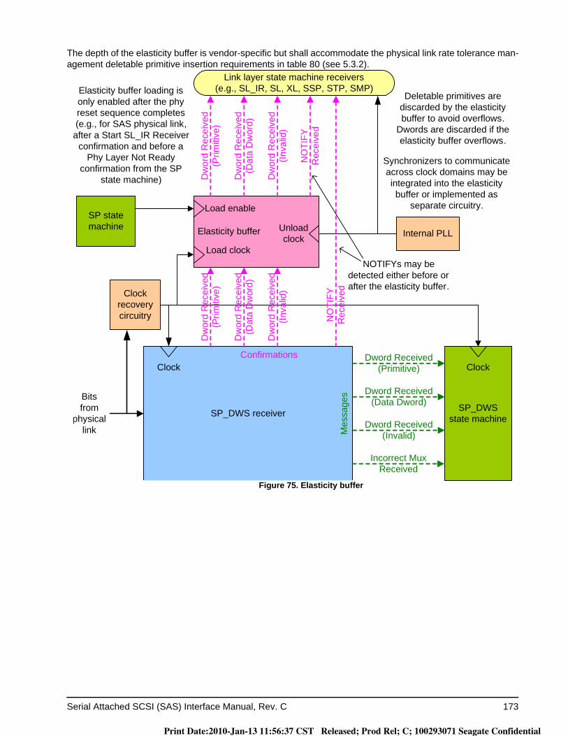
Serial Attached SCSI (SAS) Interface Manual, Rev. C 173
The depth of the elasticity buffer is vendor-specific but shall accommodate the physical link rate tolerance man-agement deletable primitive insertion requirements in table 80 (see 5.3.2).
Figure 75. Elasticity buffer
Elasticity buffer Internal PLL
SP_DWS receiver
Dword Received (Primitive)
Dword Received (Data Dword)
Dword Received (Invalid)
Incorrect Mux Received
Load clock
Unload clock
Clock recovery circuitry
Bits from
physical link
SP_DWS state machine
Clock Clock
Dw
ord
Rec
eive
d (P
rimiti
ve)
Dw
ord
Rec
eive
d (D
ata
Dw
ord)
Dw
ord
Rec
eive
d (In
valid
)
Link layer state machine receivers(e.g., SL_IR, SL, XL, SSP, STP, SMP)
Dw
ord
Rec
eive
d (P
rimiti
ve)
Dw
ord
Rec
eive
d (D
ata
Dw
ord)
Dw
ord
Rec
eive
d (In
valid
)
ConfirmationsM
essa
ges
Synchronizers to communicate across clock domains may be integrated into the elasticity buffer or implemented as
separate circuitry.
NO
TIFY
Rec
eive
d
NO
TIFY
Rec
eive
d
NOTIFYs may be detected either before or after the elasticity buffer.
SP state machine
Load enable
Elasticity buffer loading is only enabled after the phy reset sequence completes (e.g., for SAS physical link,
after a Start SL_IR Receiver confirmation and before a
Phy Layer Not Ready confirmation from the SP
state machine)
Deletable primitives are discarded by the elasticity buffer to avoid overflows.
Dwords are discarded if the elasticity buffer overflows.
Print Date:2010-Jan-13 11:56:37 CST Released; Prod Rel; C; 100293071 Seagate Confidential
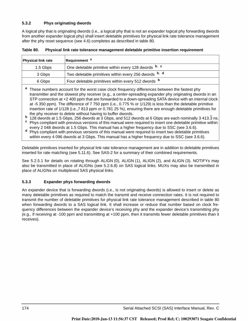
174 Serial Attached SCSI (SAS) Interface Manual, Rev. C
5.3.2 Phys originating dwords
A logical phy that is originating dwords (i.e., a logical phy that is not an expander logical phy forwarding dwords from another expander logical phy) shall insert deletable primitives for physical link rate tolerance management after the phy reset sequence (see 4.6) completes as described in table 80.
Deletable primitives inserted for physical link rate tolerance management are in addition to deletable primitives inserted for rate matching (see 5.11.6). See SAS-2 for a summary of their combined requirements.
See 5.2.5.1 for details on rotating through ALIGN (0), ALIGN (1), ALIGN (2), and ALIGN (3). NOTIFYs may also be transmitted in place of ALIGNs (see 5.2.6.8) on SAS logical links. MUXs may also be transmitted in place of ALIGNs on multiplexed SAS physical links.
5.3.3 Expander phys forwarding dwords
An expander device that is forwarding dwords (i.e., is not originating dwords) is allowed to insert or delete as many deletable primitives as required to match the transmit and receive connection rates. It is not required to transmit the number of deletable primitives for physical link rate tolerance management described in table 80when forwarding dwords to a SAS logical link. It shall increase or reduce that number based on clock fre-quency differences between the expander device’s receiving phy and the expander device’s transmitting phy (e.g., if receiving at -100 ppm and transmitting at +100 ppm, then it transmits fewer deletable primitives than it receives).
Table 80. Physical link rate tolerance management deletable primitive insertion requirement
Physical link rate Requirement a
1.5 Gbps One deletable primitive within every 128 dwords b, c
3 Gbps Two deletable primitives within every 256 dwords b, d
6 Gbps Four deletable primitives within every 512 dwords b
a These numbers account for the worst case clock frequency differences between the fastest phy transmitter and the slowest phy receiver (e.g., a center-spreading expander phy originating dwords in an STP connection at +2 400 ppm that are forwarded to a down-spreading SATA device with an internal clock at -5 350 ppm). The difference of 7 750 ppm (i.e., 0.775 % or 1/129) is less than the deletable primitive insertion rate of 1/128 (i.e.,7 813 ppm or 0.781 25 %), ensuring there are enough deletable primitives for the phy receiver to delete without having to buffer dwords.
b 128 dwords at 1.5 Gbps, 256 dwords at 3 Gbps, and 512 dwords at 6 Gbps are each nominally 3 413.3 ns.c Phys compliant with previous versions of this manual were required to insert one deletable primitive within
every 2 048 dwords at 1.5 Gbps. This manual has a higher frequency due to SSC (see 3.6.6).d Phys compliant with previous versions of this manual were required to insert two deletable primitives
within every 4 096 dwords at 3 Gbps. This manual has a higher frequency due to SSC (see 3.6.6).
Print Date:2010-Jan-13 11:56:37 CST Released; Prod Rel; C; 100293071 Seagate Confidential
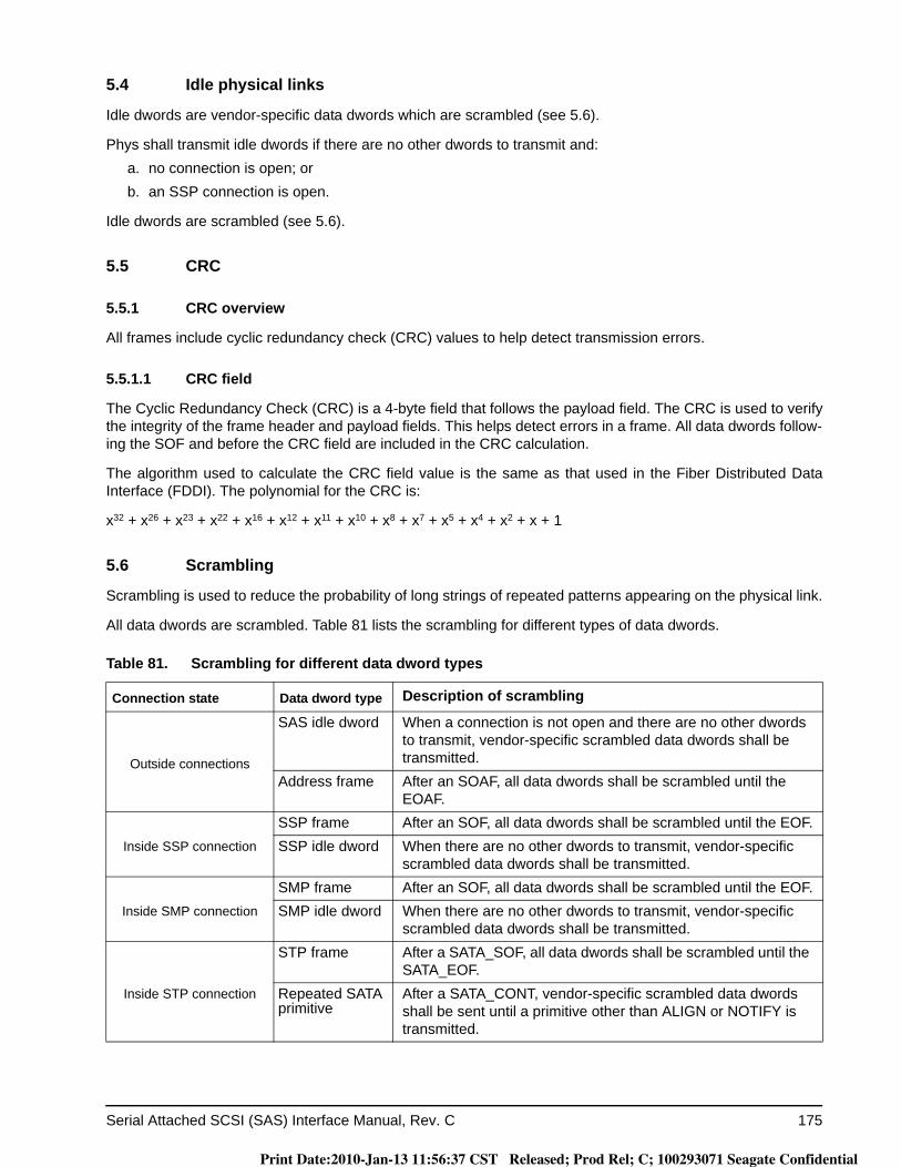
Serial Attached SCSI (SAS) Interface Manual, Rev. C 175
5.4 Idle physical links
Idle dwords are vendor-specific data dwords which are scrambled (see 5.6).
Phys shall transmit idle dwords if there are no other dwords to transmit and:a. no connection is open; orb. an SSP connection is open.
Idle dwords are scrambled (see 5.6).
5.5 CRC
5.5.1 CRC overview
All frames include cyclic redundancy check (CRC) values to help detect transmission errors.
5.5.1.1 CRC field
The Cyclic Redundancy Check (CRC) is a 4-byte field that follows the payload field. The CRC is used to verify the integrity of the frame header and payload fields. This helps detect errors in a frame. All data dwords follow-ing the SOF and before the CRC field are included in the CRC calculation.
The algorithm used to calculate the CRC field value is the same as that used in the Fiber Distributed Data Interface (FDDI). The polynomial for the CRC is:
x32 + x26 + x23 + x22 + x16 + x12 + x11 + x10 + x8 + x7 + x5 + x4 + x2 + x + 1
5.6 Scrambling
Scrambling is used to reduce the probability of long strings of repeated patterns appearing on the physical link.
All data dwords are scrambled. Table 81 lists the scrambling for different types of data dwords.
Table 81. Scrambling for different data dword types
Connection state Data dword type Description of scrambling
Outside connections
SAS idle dword When a connection is not open and there are no other dwords to transmit, vendor-specific scrambled data dwords shall be transmitted.
Address frame After an SOAF, all data dwords shall be scrambled until the EOAF.
Inside SSP connection
SSP frame After an SOF, all data dwords shall be scrambled until the EOF.SSP idle dword When there are no other dwords to transmit, vendor-specific
scrambled data dwords shall be transmitted.
Inside SMP connection
SMP frame After an SOF, all data dwords shall be scrambled until the EOF.SMP idle dword When there are no other dwords to transmit, vendor-specific
scrambled data dwords shall be transmitted.
Inside STP connection
STP frame After a SATA_SOF, all data dwords shall be scrambled until the SATA_EOF.
Repeated SATA primitive
After a SATA_CONT, vendor-specific scrambled data dwords shall be sent until a primitive other than ALIGN or NOTIFY is transmitted.
Print Date:2010-Jan-13 11:56:37 CST Released; Prod Rel; C; 100293071 Seagate Confidential

176 Serial Attached SCSI (SAS) Interface Manual, Rev. C
Data dwords being transmitted are XORed with a defined pattern to produce a scrambled value encoded and transmitted on the physical link. Received data dwords are XORed with the same pattern after decoding to pro-duce the original data dword value, provided there are no transmission errors.
The pattern that is XORed with the data dwords is defined by the output of a linear feedback shift register implemented with the following polynomial:
G(x) = x16 + x15 + x13 + x4 + 1.
The output of the pattern generator is 16 bits wide. For each data dword the output of the generator is applied to the lower 16 bits (i.e., bits 15 through 0) of the 32-bit data dword being transmitted or received; the next out-put of the generator is applied to the upper 16 bits (i.e., bits 31 through 16).
The value of the linear feedback shift register is initialized at each SOF and SOAF to FFFFh.
5.7 Address frames
5.7.1 Address frames overview
Address frames are used for the identification sequence and for connection requests. The address frame fol-lows an SOAF and ends with an EOAF. Address frames are only sent outside connections. Address frames are not terminated early. All data dwords in an address frame are scrambled.
Table 82 defines the address frame format.
The ADDRESS FRAME TYPE field indicates the type of address frame and is defined in table 83. This field determines the definition of the frame type dependent bytes.
The CRC field contains a CRC value (see 5.5) that is computed over the entire address frame prior to the CRCfield.
Address frames with unknown address frame types, incorrect lengths, or CRC errors are ignored by the drive.
Table 82. Address frame format
Byte\Bit 7 6 5 4 3 2 1 0
0 ADDRESS FRAME TYPE
1Frame type dependent bytes
27
28 (MSB)CRC
31 (LSB)
Table 83. Address frame types
Code Frame type Description
0h Identify Identification sequence
1h Open Connection request
All others Reserved
Print Date:2010-Jan-13 11:56:37 CST Released; Prod Rel; C; 100293071 Seagate Confidential
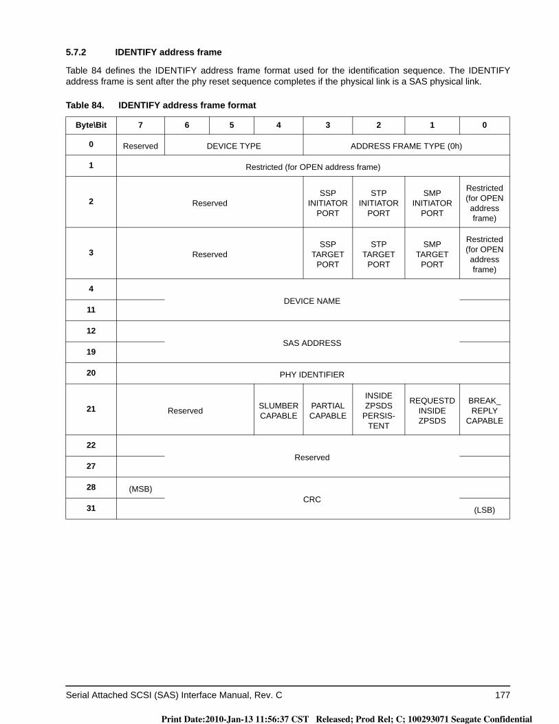
Serial Attached SCSI (SAS) Interface Manual, Rev. C 177
5.7.2 IDENTIFY address frame
Table 84 defines the IDENTIFY address frame format used for the identification sequence. The IDENTIFY address frame is sent after the phy reset sequence completes if the physical link is a SAS physical link.
Table 84. IDENTIFY address frame format
Byte\Bit 7 6 5 4 3 2 1 0
0 Reserved DEVICE TYPE ADDRESS FRAME TYPE (0h)
1 Restricted (for OPEN address frame)
2 ReservedSSP
INITIATOR PORT
STP INITIATOR
PORT
SMP INITIATOR
PORT
Restricted (for OPEN address frame)
3 ReservedSSP
TARGET PORT
STP TARGET
PORT
SMP TARGET
PORT
Restricted (for OPEN address frame)
4DEVICE NAME
11
12SAS ADDRESS
19
20 PHY IDENTIFIER
21 Reserved SLUMBER CAPABLE
PARTIAL CAPABLE
INSIDE ZPSDS
PERSIS-TENT
REQUESTD INSIDE ZPSDS
BREAK_ REPLY
CAPABLE
22Reserved
27
28 (MSB)CRC
31 (LSB)
Print Date:2010-Jan-13 11:56:37 CST Released; Prod Rel; C; 100293071 Seagate Confidential
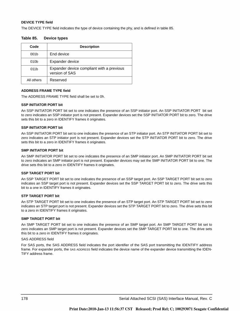
178 Serial Attached SCSI (SAS) Interface Manual, Rev. C
DEVICE TYPE fieldThe DEVICE TYPE field indicates the type of device containing the phy, and is defined in table 85.
ADDRESS FRAME TYPE fieldThe ADDRESS FRAME TYPE field shall be set to 0h.
SSP INITIATOR PORT bitAn SSP INITIATOR PORT bit set to one indicates the presence of an SSP initiator port. An SSP INITIATOR PORT bit set to zero indicates an SSP initiator port is not present. Expander devices set the SSP INITIATOR PORT bit to zero. The drive sets this bit to a zero in IDENTIFY frames it originates.
SSP INITIATOR PORT bit An SSP INITIATOR PORT bit set to one indicates the presence of an STP initiator port. An STP INITIATOR PORT bit set to zero indicates an STP initiator port is not present. Expander devices set the STP INITIATOR PORT bit to zero. The drive sets this bit to a zero in IDENTIFY frames it originates.
SMP INITIATOR PORT bit An SMP INITIATOR PORT bit set to one indicates the presence of an SMP initiator port. An SMP INITIATOR PORT bit set to zero indicates an SMP initiator port is not present. Expander devices may set the SMP INITIATOR PORT bit to one. The drive sets this bit to a zero in IDENTIFY frames it originates.
SSP TARGET PORT bitAn SSP TARGET PORT bit set to one indicates the presence of an SSP target port. An SSP TARGET PORT bit set to zero indicates an SSP target port is not present. Expander devices set the SSP TARGET PORT bit to zero. The drive sets this bit to a one in IDENTIFY frames it originates.
STP TARGET PORT bitAn STP TARGET PORT bit set to one indicates the presence of an STP target port. An STP TARGET PORT bit set to zero indicates an STP target port is not present. Expander devices set the STP TARGET PORT bit to zero. The drive sets this bit to a zero in IDENTIFY frames it originates.
SMP TARGET PORT bitAn SMP TARGET PORT bit set to one indicates the presence of an SMP target port. An SMP TARGET PORT bit set to zero indicates an SMP target port is not present. Expander devices set the SMP TARGET PORT bit to one. The drive sets this bit to a zero in IDENTIFY frames it originates.
SAS ADDRESS field
For SAS ports, the SAS ADDRESS field indicates the port identifier of the SAS port transmitting the IDENTIFY address frame. For expander ports, the SAS ADDRESS field indicates the device name of the expander device transmitting the IDEN-TIFY address frame.
Table 85. Device types
Code Description
001b End device
010b Expander device
011b Expander device compliant with a previous version of SAS
All others Reserved
Print Date:2010-Jan-13 11:56:37 CST Released; Prod Rel; C; 100293071 Seagate Confidential

Serial Attached SCSI (SAS) Interface Manual, Rev. C 179
DEVICE NAME field
The DEVICE NAME field specifies the device name (see 2.2.4) of the SAS device or expander device transmitting the IDENTIFY address frame. A DEVICE NAME field set to 00000000 00000000h specifies the device name is not provided in this field.
Note. In expander devices, the DEVICE NAME field, if not set to 00000000 00000000h, contains the same value as the SAS ADDRESS field.
SAS ADDRESS fieldFor SAS ports, the SAS ADDRESS field specifies the port identifier (see 2.2.5) of the SAS port transmitting the IDENTIFY address frame. For expander ports, the SAS ADDRESS field specifies the device name (see 2.2.4) of the expander device transmitting the IDENTIFY address frame.
PHY IDENTIFIER fieldThe PHY IDENTIFIER field indicates the phy identifier of the phy transmitting the IDENTIFY address frame.
SLUMBER CAPABLE bitThe SLUMBER CAPABLE bit set to one indicates that the phy is capable of supporting the slumber phy power condition (see SPL). The bit set to zero indicates that the phy is not capable of supporting the slumber phy power condition.
If link multiplexing is enabled (see 4.8) or optical mode is enabled, then the PARTIAL CAPABLE bit and the bit shall be set to zero.
PARTIAL CAPABLE bitThe PARTIAL CAPABLE bit set to one indicates that the phy is capable of supporting the partial phy power condition (see SPL). The PARTIAL CAPABLE bit set to zero indicates that the phy is not capable of supporting the partial phy power con-dition.
INSIDE ZPSDS PERSISTENT bitThe INSIDE ZPSDS PERSISTENT bit indicates the value of the INSIDE ZPSDS PERSISTENT bit in the zone phy informa-tion (see SPL) at the time the IDENTIFY address frame is transmitted. If the phy transmitting the IDENTIFY address frame is contained in an end device, a non-zoning expander device, or a zoning expander device with zoning disabled, then the INSIDE ZPSDS PERSISTENT bit shall be set to zero.
REQUESTD INSIDE ZPSDS bit
The REQUESTD INSIDE ZPSDS bit indicates the value of the REQUESTD INSIDE ZPSDS bit bit in the zone phy informa-tion (see SPL) at the time the IDENTIFY address frame is transmitted. If the phy transmitting the IDENTIFY address frame is contained in an end device, a non-zoning expander device, or a zoning expander device with zoning disabled, then the REQUESTD INSIDE ZPSDS bit bit shall be set to zero.
BREAK_ REPLY CAPABLE bitThe BREAK_ REPLY CAPABLE bit indicates that the phy is capable of responding to received BREAK primitive sequences with a BREAK_REPLY primitive sequence (see 5.11.5).
CRC fieldThe CRC field is defined in 5.7.1.
Print Date:2010-Jan-13 11:56:37 CST Released; Prod Rel; C; 100293071 Seagate Confidential

180 Serial Attached SCSI (SAS) Interface Manual, Rev. C
5.7.3 OPEN address frame
Table 86 defines the OPEN address frame format used for connection requests.
INITIATOR PORT bitAn INITIATOR PORT bit set to one indicates the source port is acting as a SAS initiator port. An INITIATOR PORT bit set to zero indicates the source port is acting as a SAS target port. If a SAS target/initiator port sets the INITIATOR PORT bit to one, it operates only in its initiator role during the connection. If a target/initiator port sets the INITIATOR PORT bit to zero, it operates only in its target role during the connection.
If a SAS target/initiator port accepts an OPEN address frame with the INITIATOR PORT bit set to one, it operates only in its target role during the connection. If a SAS target/initiator port accepts an OPEN address frame with the INITIATOR PORTbit set to zero, it operates only in its initiator role during the connection.
Table 86. OPEN address frame format
Byte\Bit 7 6 5 4 3 2 1 0
0 INITIATOR PORT PROTOCOL ADDRESS FRAME TYPE (1h)
1 FEATURES CONNECTION RATE
2 (MSB)INITIATOR CONNECTION TAGE
3 (LSB)
4
DESTINATION SAS ADDRESS11
12
SOURCE SAS ADDRESS19
20 SOURCE ZONE GROUP
21 PATHWAY BLOCKES COUNT
22 (MSB)ARBITRATION WAIT TIME
23 (LSB)
24
MORE COMPATIBLE FEATURES27
28 (MSB)CRC
31 (LSB)
Print Date:2010-Jan-13 11:56:37 CST Released; Prod Rel; C; 100293071 Seagate Confidential
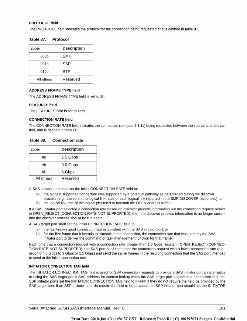
Serial Attached SCSI (SAS) Interface Manual, Rev. C 181
PROTOCOL fieldThe PROTOCOL field indicates the protocol for the connection being requested and is defined in table 87.
ADDRESS FRAME TYPE fieldThe ADDRESS FRAME TYPE field is set to 1h.
FEATURES fieldThe FEATURES field is set to zero.
CONNECTION RATE fieldThe CONNECTION RATE field indicates the connection rate (see 2.1.11) being requested between the source and destina-tion, and is defined in table 88.
A SAS initiator port shall set the initial CONNECTION RATE field to:a) the highest supported connection rate supported by a potential pathway as determined during the discover
process (e.g., based on the logical link rates of each logical link reported in the SMP DISCOVER responses); orb) the logical link rate of the logical phy used to transmit the OPEN address frame.
If a SAS initiator port selected a connection rate based on discover process information but the connection request results in OPEN_REJECT (CONNECTION RATE NOT SUPPORTED), then the discover process information is no longer current and the discover process should be run again.
A SAS target port shall set the initial CONNECTION RATE field to:a) the last known good connection rate established with the SAS initiator port; orb) for the first frame that it intends to transmit in the connection, the connection rate that was used by the SAS
initiator port to deliver the command or task management function for that frame.
Each time that a connection request with a connection rate greater than 1.5 Gbps results in OPEN_REJECT (CONNEC-TION RATE NOT SUPPORTED), the SAS port shall reattempt the connection request with a lower connection rate (e.g., drop from 6 Gbps to 3 Gbps or 1.5 Gbps) and send the same frames in the resulting connection that the SAS port intended to send at the initial connection rate.
INITIATOR CONNECTION TAG fieldThe INITIATOR CONNECTION TAG field is used for SSP connection requests to provide a SAS initiator port an alternative to using the SAS target port’s SAS address for context lookup when the SAS target port originates a connection request. SSP initiator ports set the INITIATOR CONNECTION TAG field to FFFFh if they do not require the field be provided by the SAS target port. If an SSP initiator port do require the field to be provided, an SSP initiator port should set the INITIATOR
Table 87. Protocol
Code Description
000b SMP
001b SSP
010b STP
All others Reserved
Table 88. Connection rate
Code Description
8h 1.5 Gbps
9h 3.0 Gbps
Ah 6 GbpsAll others Reserved
Print Date:2010-Jan-13 11:56:37 CST Released; Prod Rel; C; 100293071 Seagate Confidential
182 Serial Attached SCSI (SAS) Interface Manual, Rev. C
CONNECTION TAG field to a unique value per SAS target port. When requesting a connection to a SAS initiator port, a SAS target port shall set the INITIATOR CONNECTION TAG field to the most recent value received or the value received in one of the connection requests for one of the outstanding commands or task management functions from the SAS initiator port. A SAS initiator port shall:
a) use the same INITIATOR CONNECTION TAG field value for all connection requests to the same SAS target port, and
b) only change the INITIATOR CONNECTION TAG field value when it has no commands or task management functions outstanding to that SAS target port.
SAS target ports are not required to check consistency of the INITIATOR CONNECTION TAG field in different connection requests from the same SAS initiator port. SMP initiator ports shall set the INITIATOR CONNECTION TAG field to FFFFh for SMP connection requests.
DESTINATION SAS ADDRESS fieldThe DESTINATION SAS ADDRESS field indicates the port identifier of the SAS port to which a connection is being requested.
SOURCE SAS ADDRESSThe SOURCE SAS ADDRESS field indicates the port identifier of the SAS port that originated the OPEN address frame.
SOURCE ZONE GROUP field
The SOURCE ZONE GROUP field identifies the zone group of the phy making the connection request. The SOURCE ZONE GROUP field shall be:
a) set to 00h when transmitted by an end device;b) set to 00h when transmitted by an expander device on a phy with the INSIDE ZPSDS bit set to zero;c) set to the source zone group for the outgoing connection request as described in SPL when trans-
mitted by an expander device on a phy with the INSIDE ZPSDS bit set to one;d) ignored when received by an end device;e) ignored when received by an expander device on a phy with the INSIDE ZPSDS bit set to zero; orf) used to determine the source zone group for the incoming connection request as described in SPL
when received by an expander device on a phy with the INSIDE ZPSDS bit set to one.
PATHWAY BLOCKED COUNT fieldThe PATHWAY BLOCKED COUNT field indicates the number of times the port has retried this connection request due to receiving OPEN_REJECT (PATHWAY BLOCKED) OPEN_REJECT (RESERVED STOP 0), or OPEN_REJECT (RESERVED STOP 1). The drive does not increment the PATHWAY BLOCKED COUNT value past FFh. If the drive changes the destination of a connection request, it sets the PATHWAY BLOCKED COUNT of 00h.
Print Date:2010-Jan-13 11:56:37 CST Released; Prod Rel; C; 100293071 Seagate Confidential
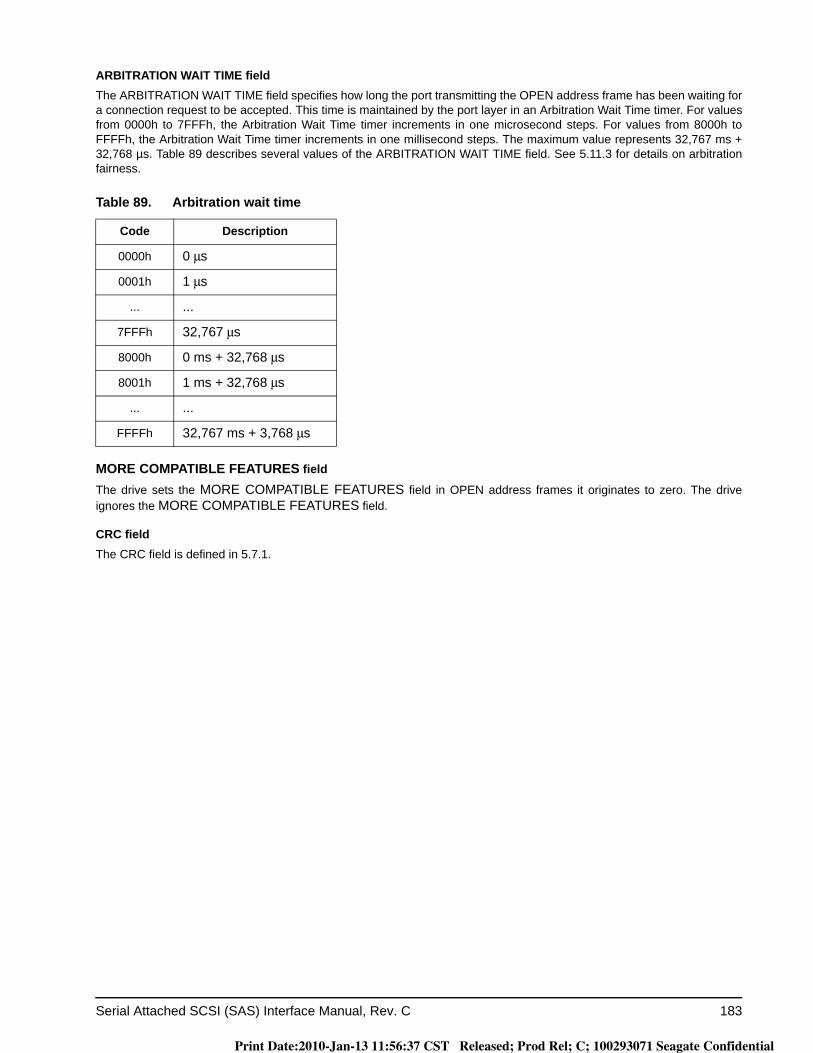
Serial Attached SCSI (SAS) Interface Manual, Rev. C 183
ARBITRATION WAIT TIME fieldThe ARBITRATION WAIT TIME field specifies how long the port transmitting the OPEN address frame has been waiting for a connection request to be accepted. This time is maintained by the port layer in an Arbitration Wait Time timer. For values from 0000h to 7FFFh, the Arbitration Wait Time timer increments in one microsecond steps. For values from 8000h to FFFFh, the Arbitration Wait Time timer increments in one millisecond steps. The maximum value represents 32,767 ms + 32,768 µs. Table 89 describes several values of the ARBITRATION WAIT TIME field. See 5.11.3 for details on arbitration fairness.
MORE COMPATIBLE FEATURES field
The drive sets the MORE COMPATIBLE FEATURES field in OPEN address frames it originates to zero. The drive ignores the MORE COMPATIBLE FEATURES field.
CRC fieldThe CRC field is defined in 5.7.1.
Table 89. Arbitration wait time
Code Description
0000h 0 μs
0001h 1 μs
... ...
7FFFh 32,767 μs
8000h 0 ms + 32,768 μs
8001h 1 ms + 32,768 μs
... ...
FFFFh 32,767 ms + 3,768 μs
Print Date:2010-Jan-13 11:56:37 CST Released; Prod Rel; C; 100293071 Seagate Confidential
184 Serial Attached SCSI (SAS) Interface Manual, Rev. C
5.8 Link reset sequence
5.8.1 Link reset sequence overview
For SAS, a link reset sequence is either:a) the following sequence:
1)a phy reset sequence indicating that the physical link is using SAS rather than SATA; and2)an identification sequence,
or
b) the following sequence:1)a phy reset sequence indicating that the physical link is using SAS rather than SATA;2)a hard reset sequence;3)another phy reset sequence indicating that the physical link is using SAS rather than SATA; and4)an identification sequence.
An identification sequence occurs when a logical phy:a) transmits one or three IDENTIFY address frames (see 5.7.2); andb) does not receive a HARD_RESET primitive sequence.
A hard reset sequence occurs when, after the phy reset sequence, a logical phy:a) transmits a HARD_RESET primitive sequence (see 5.2.6.7); orb) receives a HARD_RESET primitive sequence.
Print Date:2010-Jan-13 11:56:37 CST Released; Prod Rel; C; 100293071 Seagate Confidential
Serial Attached SCSI (SAS) Interface Manual, Rev. C 185
Figure 76 shows two phys with multiplexing disabled performing the identification sequence. Only one IDEN-TIFY address frame is shown in this example.
Figure 76. Identification sequence
Time
SO
AF
data
dw
ord
0
ALI
GN
(1)
ALI
GN
(1)
ALI
GN
(1)
EO
AF
data
dw
ord
7 (i.
e., C
RC
)
Phy A TXPhy B RX
SO
AF
data
dw
ord
0
ALI
GN
(1)
ALI
GN
(1)
ALI
GN
(1)
EO
AF
data
dw
ord
7 (i.
e., C
RC
)
data
dw
ord
data
dw
ord
Phy A RXPhy B TX
Phy reset sequence Identification sequence
logi
cal l
ink
0 dw
ord
data
dw
ord
data
dw
ord
data
dw
ord
data
dw
ord
IDENTIFYaddress frame
Phy reset sequence Identification sequenceIDENTIFY
address frame
logi
cal l
ink
0 dw
ord
logi
cal l
ink
0 dw
ord
Note: Phys transmit deletable primitives for physical link rate tolerance management after the phy reset sequence.
data
dw
ord
data
dw
ord
data
dw
ord
Logicallink 0
Logicallink 0
logi
cal l
ink
0 dw
ord
logi
cal l
ink
0 dw
ord
Print Date:2010-Jan-13 11:56:37 CST Released; Prod Rel; C; 100293071 Seagate Confidential
186 Serial Attached SCSI (SAS) Interface Manual, Rev. C
Figure 77 shows phy A attempting to perform the identification sequence and phy B performing the hard reset sequence. Because phy A receives a HARD_RESET primitive sequence, a hard reset sequence actually occurs. Multiplexing is disabled and only one IDENTIFY address frame is shown in this example.
Figure 77. Hard reset sequence
Each logical phy receives an IDENTIFY address frame or a HARD_RESET primitive sequence from the logical phy to which it is attached.
If a logical phy receives a valid IDENTIFY address frame (see 5.7.2) within 1 ms of phy reset sequence com-pletion, then the SAS address in the outgoing IDENTIFY address frame(s) and the SAS address in the incom-ing IDENTIFY address frame determine the port to which the logical phy belongs (see 2.1.4). The logical phy ignores subsequent IDENTIFY address frames and HARD_RESET primitives until another phy reset sequence occurs.
If a logical phy receives a HARD_RESET primitive sequence within 1 ms of phy reset sequence completion, then the logical phy shall consider this to be a reset event, and the port containing the logical phy shall process a hard reset (see 2.3.2).
If a logical phy does not receive a HARD_RESET primitive sequence or a valid IDENTIFY address frame within 1 ms of phy reset sequence completion, then the physical phy containing the logical phy shall restart the phy reset sequence.
Time
SOAF
data
dw
ord
0
ALI
GN
(1)
ALI
GN
(1)
ALI
GN
(1)
EOAF
data
dw
ord
7 (i.
e., C
RC
)
Phy A TXPhy B RX
HAR
D_R
ESET
ALI
GN
(1)
ALI
GN
(1)
ALI
GN
(1)
HAR
D_R
ESET
data
dw
ord
data
dw
ord
Phy A RXPhy B TX
Phy reset sequence Hard reset sequence
data
dw
ord
IDENTIFYaddress frame
Phy reset sequence Hard reset sequenceHARD_RESET
primitive sequence
Note: Phys transmit deletable primitives for physical link rate tolerance management after the phy reset sequence.
HAR
D_R
ESET
HAR
D_R
ESET
HAR
D_R
ESET
HAR
D_R
ESET
COMINIT
COMINIT
Phy reset sequence
Phy reset sequence
data
dw
ord
data
dw
ord
data
dw
ord
data
dw
ord
data
dw
ord
data
dw
ord
Print Date:2010-Jan-13 11:56:37 CST Released; Prod Rel; C; 100293071 Seagate Confidential

Serial Attached SCSI (SAS) Interface Manual, Rev. C 187
5.8.2 Expander device handling of link reset sequences
After completing the link reset sequence on a phy and completing internal initialization, the ECM within an expander device shall be capable of routing connection requests through that phy. The expander device may return OPEN_REJECT (NO DESTINATION) until it is ready to process connection requests.
The ECM of an externally configurable expander device is dependent on the completion of the discover pro-cess (see SAS-2) for routing connection requests using the table routing method.
Print Date:2010-Jan-13 11:56:37 CST Released; Prod Rel; C; 100293071 Seagate Confidential

188 Serial Attached SCSI (SAS) Interface Manual, Rev. C
5.9 Entering low phy power conditionFigure 78 shows the sequence to transition from active phy power condition to a low phy power condition. The sequence proceeds as follows:
1) phy A transmits a PS_REQ (PARTIAL) or PS_REQ (SLUMBER) to phy B (see 5.2.6.13);2) phy B transmits PS_ACK to phy A (see 5.2.6.11);3) both phys remember all negotiated settings (e.g., link rate, training, and SSC); and4) both phys transition to D.C. idle.
Figure 78. SAS transition to low phy power condition
After sending a PS_REQ if no PS_ACK is received within a power condition request timeout, then the transi-tion to the low phy power condition is aborted and the phy remains in the active phy power
5.10 SAS domain changes (BROADCAST (CHANGE) usage
Expander devices shall originate Broadcast (Change) when certain events occur (e.g.:a. after an expander phy has lost dword synchronization;b. after the link reset sequence completes; andc. after the expander device receives BROADCAST (CHANGE)).
See 5.2.6.3 and SAS-2 for the complete requirements for the expander to originate Broadcast (Change).
SAS initiator ports may originate Broadcast (Change) to force other SAS initiator ports and expander ports to re-run the discover process. SAS target ports not originate Broadcast (Change).
After power on or receiving BROADCAST (CHANGE), an application client in each SAS initiator port should scan the SAS domain using the discover process to search for SAS initiator devices, SAS target devices, and expander devices.
PS_REQ PS_ACK
Phy A RxPhy B Tx
Phy A TxPhy B Rx
Time (not to scale)
Dwords transmitted by the link layer
Long time
Key:
D.C. idle
Print Date:2010-Jan-13 11:56:37 CST Released; Prod Rel; C; 100293071 Seagate Confidential
Serial Attached SCSI (SAS) Interface Manual, Rev. C 189
5.11 Connections
5.11.1 Connections overview
A connection is opened between a SAS initiator port and a SAS target port before communication begins. A connection is established between one SAS initiator phy in the SAS initiator port and one SAS target phy in the SAS target port.
SSP initiator ports open SSP connections to transmit SCSI commands, task management functions, or transfer data. SSP target ports open SSP connections to transfer data or transmit status.
SMP initiator ports open SMP connections to transmit SMP requests and receive SMP responses. Reference SAS-2 for a description of SMP.
STP initiator ports and STP target ports open STP connections to transmit SATA frames. An STP target port in an expander device opens STP connections on behalf of SATA devices. Reference SAS-2 for a description of STP.
The OPEN address frame is used to request that a connection be opened. AIP, OPEN_ACCEPT and OPEN_REJECT are the responses to an OPEN address frame. BREAK is used to abort connection requests and to unilaterally break a connection. CLOSE is used for orderly closing a connection.
Connections use a single pathway from the SAS initiator phy to the SAS target phy. While a connection is open, only one pathway is used for that connection.
A wide port may have separate connections on each of its logical phys.
5.11.2 Opening a connection
5.11.2.1 Connection request
The OPEN address frame (see 5.7.3) is used to open a connection from a source port to a destination port using one source phy (i.e., one logical phy in the source port) and one destination phy (i.e., one logical phy in the destination port).
To make a connection request, the source port shall transmit an OPEN address frame through an available logical phy (i.e., the source phy). The source phy shall transmit idle dwords after the OPEN address frame until it receives a response or aborts the connection request with BREAK.
After transmitting an OPEN address frame, the source phy shall initialize and start a 1 ms Open Timeout timer. Whenever an AIP is received, the source phy shall reinitialize and restart the Open Timeout timer. Source phys are not required to enforce a limit on the number of AIPs received before aborting the connection request. When any connection response is received, the source phy shall reinitialize the Open Timeout timer. If the Open Timeout timer expires before a connection response is received, then the source phy shall transmit BREAK to abort the connection request.
The OPEN address frame flows through expander devices onto intermediate logical links. If an expander device on the pathway is unable to forward the connection request, then that expander device returns OPEN_REJECT (see 5.2.6.10). If the OPEN address frame reaches the destination phy, then the destination phy returns either OPEN_ACCEPT or OPEN_REJECT unless the OPEN address frame passed an OPEN address frame from the destination phy with higher arbitration priority (see 5.11.3). Rate matching shall be used on any logical links in the pathway with negotiated logical link rates that are faster than the requested connection rate (see 5.11.6).
Print Date:2010-Jan-13 11:56:37 CST Released; Prod Rel; C; 100293071 Seagate Confidential
190 Serial Attached SCSI (SAS) Interface Manual, Rev. C
A wide port should not attempt to establish more connections to a destination port than the destination port width or the width of the narrowest logical link on the pathway to the destination port. A wide port should not attempt to establish more connections than the width of the narrowest common logical link on the pathways to the destination ports of those connections. Additional requirements for STP connection requests are defined in SAS-2. Additional requirements for SMP connection requests are defined in SAS-2.
Figure 79 shows an example of the simultaneous connection recommendations for wide ports. Multiplexing is disabled in this example.
Figure 79. Example simultaneous connection recommendations for wide ports
In figure 79, some of the recommendations are combined as follows:
a) recommendations a), b), and e) together specify that port Z should not attempt to open more than 2 connections to port C;
b) recommendations a), b), e), f), and g) together specify that if port Z has 2 connections open to ports A, B, and X, it should not attempt to open more than 1 connection to port C. If it has 6 connections open to ports A, B, D, E, W, X, and Y, it should not attempt to open more than 1 connection to port C; and
c) recommendations a), c), and h) together specify that port Z should not attempt to open more than 1 connection to port D. If it has a connection open to port Y, it should not attempt to open another connection to port D until the first connection is closed.
Port Z Expander device W
Expander device X
a) A source port should not attempt to open more than 7
connections using this wide link
b) A source port should not attempt to open more than
3 connections over this wide link
Expander device Y
c) A source port should not attempt to open more than 1 connection using
this physical link
f) A source port should not attempt to open more than 1 connection using this physical link
h) A source port should not attempt to open more than 4 connections using
this wide link
Port A
Port B
Port C
Port D
A source port considers all these recommendations
simultaneously
Port Ed) A source port should not attempt to open more than 2 connections using this
wide link
7-wide
3-wide
4-wide
2-wide
g) A source port should not attempt to open more than 1 connection using this physical link
e) A source port should not attempt to open more than 2 connections using this wide link
2-wide
Print Date:2010-Jan-13 11:56:37 CST Released; Prod Rel; C; 100293071 Seagate Confidential
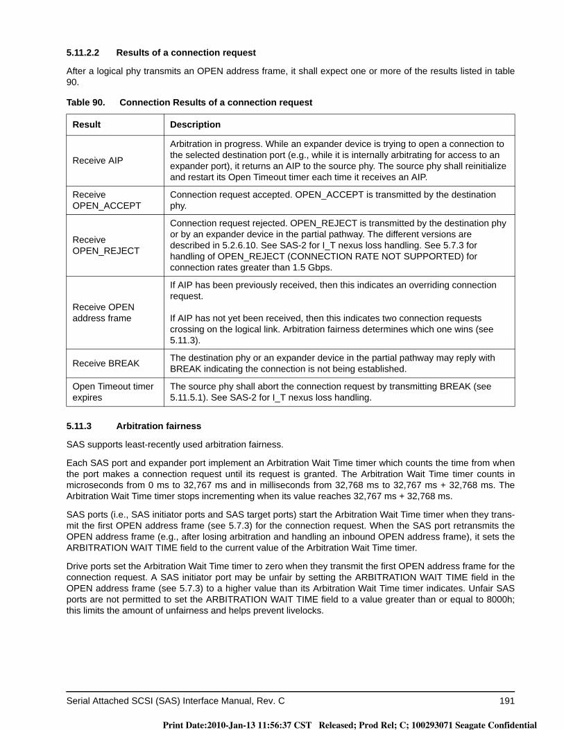
Serial Attached SCSI (SAS) Interface Manual, Rev. C 191
5.11.2.2 Results of a connection request
After a logical phy transmits an OPEN address frame, it shall expect one or more of the results listed in table 90.
5.11.3 Arbitration fairness
SAS supports least-recently used arbitration fairness.
Each SAS port and expander port implement an Arbitration Wait Time timer which counts the time from when the port makes a connection request until its request is granted. The Arbitration Wait Time timer counts in microseconds from 0 ms to 32,767 ms and in milliseconds from 32,768 ms to 32,767 ms + 32,768 ms. The Arbitration Wait Time timer stops incrementing when its value reaches 32,767 ms + 32,768 ms.
SAS ports (i.e., SAS initiator ports and SAS target ports) start the Arbitration Wait Time timer when they trans-mit the first OPEN address frame (see 5.7.3) for the connection request. When the SAS port retransmits the OPEN address frame (e.g., after losing arbitration and handling an inbound OPEN address frame), it sets the ARBITRATION WAIT TIME field to the current value of the Arbitration Wait Time timer.
Drive ports set the Arbitration Wait Time timer to zero when they transmit the first OPEN address frame for the connection request. A SAS initiator port may be unfair by setting the ARBITRATION WAIT TIME field in the OPEN address frame (see 5.7.3) to a higher value than its Arbitration Wait Time timer indicates. Unfair SAS ports are not permitted to set the ARBITRATION WAIT TIME field to a value greater than or equal to 8000h; this limits the amount of unfairness and helps prevent livelocks.
Table 90. Connection Results of a connection request
Result Description
Receive AIP
Arbitration in progress. While an expander device is trying to open a connection to the selected destination port (e.g., while it is internally arbitrating for access to an expander port), it returns an AIP to the source phy. The source phy shall reinitialize and restart its Open Timeout timer each time it receives an AIP.
Receive OPEN_ACCEPT
Connection request accepted. OPEN_ACCEPT is transmitted by the destination phy.
Receive OPEN_REJECT
Connection request rejected. OPEN_REJECT is transmitted by the destination phy or by an expander device in the partial pathway. The different versions are described in 5.2.6.10. See SAS-2 for I_T nexus loss handling. See 5.7.3 for handling of OPEN_REJECT (CONNECTION RATE NOT SUPPORTED) for connection rates greater than 1.5 Gbps.
Receive OPEN address frame
If AIP has been previously received, then this indicates an overriding connection request.
If AIP has not yet been received, then this indicates two connection requests crossing on the logical link. Arbitration fairness determines which one wins (see 5.11.3).
Receive BREAK The destination phy or an expander device in the partial pathway may reply with BREAK indicating the connection is not being established.
Open Timeout timer expires
The source phy shall abort the connection request by transmitting BREAK (see 5.11.5.1). See SAS-2 for I_T nexus loss handling.
Print Date:2010-Jan-13 11:56:37 CST Released; Prod Rel; C; 100293071 Seagate Confidential
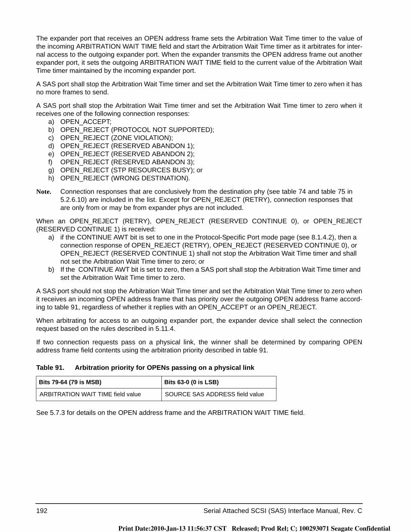
192 Serial Attached SCSI (SAS) Interface Manual, Rev. C
The expander port that receives an OPEN address frame sets the Arbitration Wait Time timer to the value of the incoming ARBITRATION WAIT TIME field and start the Arbitration Wait Time timer as it arbitrates for inter-nal access to the outgoing expander port. When the expander transmits the OPEN address frame out another expander port, it sets the outgoing ARBITRATION WAIT TIME field to the current value of the Arbitration Wait Time timer maintained by the incoming expander port.
A SAS port shall stop the Arbitration Wait Time timer and set the Arbitration Wait Time timer to zero when it has no more frames to send.
A SAS port shall stop the Arbitration Wait Time timer and set the Arbitration Wait Time timer to zero when it receives one of the following connection responses:
a) OPEN_ACCEPT;b) OPEN_REJECT (PROTOCOL NOT SUPPORTED);c) OPEN_REJECT (ZONE VIOLATION);d) OPEN_REJECT (RESERVED ABANDON 1);e) OPEN_REJECT (RESERVED ABANDON 2);f) OPEN_REJECT (RESERVED ABANDON 3);g) OPEN_REJECT (STP RESOURCES BUSY); orh) OPEN_REJECT (WRONG DESTINATION).
Note. Connection responses that are conclusively from the destination phy (see table 74 and table 75 in 5.2.6.10) are included in the list. Except for OPEN_REJECT (RETRY), connection responses that are only from or may be from expander phys are not included.
When an OPEN_REJECT (RETRY), OPEN_REJECT (RESERVED CONTINUE 0), or OPEN_REJECT (RESERVED CONTINUE 1) is received:
a) if the CONTINUE AWT bit is set to one in the Protocol-Specific Port mode page (see 8.1.4.2), then a connection response of OPEN_REJECT (RETRY), OPEN_REJECT (RESERVED CONTINUE 0), or OPEN_REJECT (RESERVED CONTINUE 1) shall not stop the Arbitration Wait Time timer and shall not set the Arbitration Wait Time timer to zero; or
b) If the CONTINUE AWT bit is set to zero, then a SAS port shall stop the Arbitration Wait Time timer and set the Arbitration Wait Time timer to zero.
A SAS port should not stop the Arbitration Wait Time timer and set the Arbitration Wait Time timer to zero when it receives an incoming OPEN address frame that has priority over the outgoing OPEN address frame accord-ing to table 91, regardless of whether it replies with an OPEN_ACCEPT or an OPEN_REJECT.
When arbitrating for access to an outgoing expander port, the expander device shall select the connection request based on the rules described in 5.11.4.
If two connection requests pass on a physical link, the winner shall be determined by comparing OPEN address frame field contents using the arbitration priority described in table 91.
See 5.7.3 for details on the OPEN address frame and the ARBITRATION WAIT TIME field.
Table 91. Arbitration priority for OPENs passing on a physical link
Bits 79-64 (79 is MSB) Bits 63-0 (0 is LSB)
ARBITRATION WAIT TIME field value SOURCE SAS ADDRESS field value
Print Date:2010-Jan-13 11:56:37 CST Released; Prod Rel; C; 100293071 Seagate Confidential
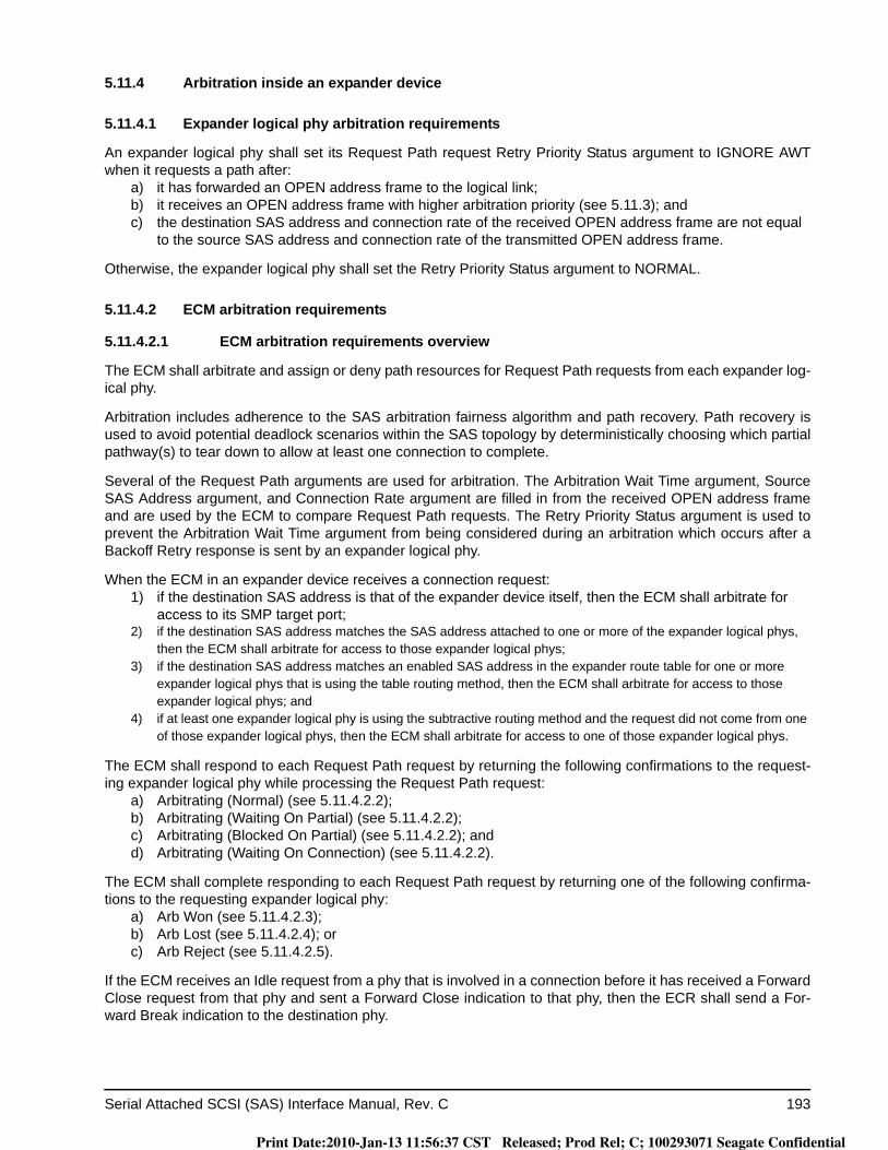
Serial Attached SCSI (SAS) Interface Manual, Rev. C 193
5.11.4 Arbitration inside an expander device
5.11.4.1 Expander logical phy arbitration requirements
An expander logical phy shall set its Request Path request Retry Priority Status argument to IGNORE AWT when it requests a path after:
a) it has forwarded an OPEN address frame to the logical link;b) it receives an OPEN address frame with higher arbitration priority (see 5.11.3); andc) the destination SAS address and connection rate of the received OPEN address frame are not equal
to the source SAS address and connection rate of the transmitted OPEN address frame.
Otherwise, the expander logical phy shall set the Retry Priority Status argument to NORMAL.
5.11.4.2 ECM arbitration requirements
5.11.4.2.1 ECM arbitration requirements overview
The ECM shall arbitrate and assign or deny path resources for Request Path requests from each expander log-ical phy.
Arbitration includes adherence to the SAS arbitration fairness algorithm and path recovery. Path recovery is used to avoid potential deadlock scenarios within the SAS topology by deterministically choosing which partial pathway(s) to tear down to allow at least one connection to complete.
Several of the Request Path arguments are used for arbitration. The Arbitration Wait Time argument, Source SAS Address argument, and Connection Rate argument are filled in from the received OPEN address frame and are used by the ECM to compare Request Path requests. The Retry Priority Status argument is used to prevent the Arbitration Wait Time argument from being considered during an arbitration which occurs after a Backoff Retry response is sent by an expander logical phy.
When the ECM in an expander device receives a connection request:1) if the destination SAS address is that of the expander device itself, then the ECM shall arbitrate for
access to its SMP target port;2) if the destination SAS address matches the SAS address attached to one or more of the expander logical phys,
then the ECM shall arbitrate for access to those expander logical phys;3) if the destination SAS address matches an enabled SAS address in the expander route table for one or more
expander logical phys that is using the table routing method, then the ECM shall arbitrate for access to those expander logical phys; and
4) if at least one expander logical phy is using the subtractive routing method and the request did not come from one of those expander logical phys, then the ECM shall arbitrate for access to one of those expander logical phys.
The ECM shall respond to each Request Path request by returning the following confirmations to the request-ing expander logical phy while processing the Request Path request:
a) Arbitrating (Normal) (see 5.11.4.2.2);b) Arbitrating (Waiting On Partial) (see 5.11.4.2.2);c) Arbitrating (Blocked On Partial) (see 5.11.4.2.2); andd) Arbitrating (Waiting On Connection) (see 5.11.4.2.2).
The ECM shall complete responding to each Request Path request by returning one of the following confirma-tions to the requesting expander logical phy:
a) Arb Won (see 5.11.4.2.3);b) Arb Lost (see 5.11.4.2.4); orc) Arb Reject (see 5.11.4.2.5).
If the ECM receives an Idle request from a phy that is involved in a connection before it has received a Forward Close request from that phy and sent a Forward Close indication to that phy, then the ECR shall send a For-ward Break indication to the destination phy.
Print Date:2010-Jan-13 11:56:37 CST Released; Prod Rel; C; 100293071 Seagate Confidential

194 Serial Attached SCSI (SAS) Interface Manual, Rev. C
5.11.4.2.2 Arbitrating confirmations
The ECM shall send an Arbitrating (Normal) confirmation after it has received a Request Path request.
The ECM shall send an Arbitrating (Waiting On Partial) confirmation if it is waiting on a partial pathway. The ECM is waiting on a partial pathway if:
a) there is a destination port capable of routing to the requested destination SAS address;b) at least one expander logical phy within the destination port supports the requested connection rate;c) each of the expander logical phys within the destination port is returning a Phy Status (Partial
Pathway) or Phy Status (Blocked Partial Pathway) response; andd) at least one of the expander logical phys within the destination port is returning a Phy Status (Partial
Pathway) response.
The ECM shall send an Arbitrating (Blocked On Partial) confirmation if it is waiting on a blocked partial path-way. The ECM is waiting on a blocked partial pathway if:
a) there is a destination port capable of routing to the requested destination SAS address;b) at least one expander logical phy within the destination port supports the requested connection rate;
andc) each of the expander logical phys within the destination port is returning a Phy Status (Blocked Partial
Pathway) response.
The ECM shall send an Arbitrating (Waiting On Connection) confirmation if it is waiting on a connection to com-plete. The ECM is waiting on a connection to complete if:
a) the connection request is blocked by an active connection; orb) there are insufficient routing resources within the expander to complete the connection request.
A connection request shall be considered blocked by an active connection when:a) there is a destination port capable of routing to the requested destination SAS address;b) at least one expander logical phy within the destination port supports the requested connection rate;c) each of the expander logical phys within the destination port is returning a Phy Status (Partial
Pathway) response, a Phy Status (Blocked Partial Pathway) response, a Phy Status (Breaking Connection) response, or a Phy Status (Connection) response; and
d) at least one of the expander logical phys within the destination port is returning a Phy Status (Connection) response.
5.11.4.2.3 Arb Won confirmation
The ECM shall generate the Arb Won confirmation when all of the following conditions are met:a) the Request Path request maps to a destination expander logical phy that:
A) supports the connection rate; andB) is not reporting a Phy Status (Partial Pathway) response, a Phy Status (Blocked Partial Pathway)
response, a Phy Status (Breaking Connection) response, or a Phy Status (Connection) response unless that expander logical phy is arbitrating for the requesting expander logical phy;
b) there are sufficient routing resources to complete the connection request;c) no higher priority Request Path requests are present with the requesting expander logical phy as the
destination; andd) the Request Path request is the highest priority Request Path request (see table 92 and table 93)
mapping to the destination expander logical phy (i.e., only send one Arb Won confirmation for Request Path requests to the same destination phy).
Print Date:2010-Jan-13 11:56:37 CST Released; Prod Rel; C; 100293071 Seagate Confidential

Serial Attached SCSI (SAS) Interface Manual, Rev. C 195
If two or more Request Path requests contend and all of the Request Path requests include a Retry Priority Status argument set to NORMAL, then the ECM shall select the winner by comparing the OPEN address frame contents described in table 92.
If two or more Request Path requests contend and one or more of the Request Path requests include a Retry Priority Status argument set to IGNORE AWT, then the ECM shall select the winner from the set of Request Path requests with Retry Priority Status arguments set to IGNORE AWT by comparing the OPEN address frame contents described in table 93.
5.11.4.2.4 Arb Lost confirmation
The ECM shall generate the Arb Lost confirmation when all of the following conditions are met:a) the Request Path request maps to a destination expander logical phy that:
A) supports the connection rate; andB) is not reporting a Phy Status (Partial Pathway) response, a Phy Status (Blocked Partial Pathway)
response, a Phy Status (Breaking Connection) response, or a Phy Status (Connection) response unless that expander logical phy is arbitrating for the requesting expander logical phy;
b) there are sufficient routing resources to complete the connection request; andc) one of the following conditions are met:
A) the destination expander logical phy is making a Request Path request with the requesting expander logical phy as its destination (i.e., when two expander logical phys both receive an OPEN address frame destined for each other, the ECM provides the Arb Lost confirmation to the expander logical phy that received the lowest priority OPEN address frame); or
B) the ECM is sending an Arb Won confirmation to another expander logical phy that is using the requesting expander logical phy as the destination.
Table 92. Arbitration priority for contending Request Path requests in the ECM when all requests have Retry Priority Status arguments of NORMAL
Bits 83-68 (83 is MSB) Bits 67-4 Bits 3-0 (0 is LSB)
ARBITRATION WAIT TIME field value SOURCE SAS ADDRESS field value CONNECTION RATE field value
Table 93. Arbitration priority for contending Request Path requests in the ECM among requests with Retry Priority Status arguments of IGNORE AWT
Bits 67-4 (67 is MSB) Bits 3-0 (0 is LSB)
SOURCE SAS ADDRESS field value CONNECTION RATE field value
Print Date:2010-Jan-13 11:56:37 CST Released; Prod Rel; C; 100293071 Seagate Confidential
196 Serial Attached SCSI (SAS) Interface Manual, Rev. C
5.11.4.2.5 Arb Reject confirmation
The ECM shall generate one of the following Arb Reject confirmations when any of the following conditions are met and all the Arb Won conditions (see 5.11.4.2.3) are not met:
1) an Arb Reject (Bad Destination) confirmation if the source expander logical phy and destination expander logical phy(s) are in the same expander port and are using the direct routing method;
2) an Arb Reject (Retry) confirmation if the expander device is unable to process the connection request because it has reduced functionality;
3) if the source expander logical phy and destination expander logical phy(s) are in the same expander port and are using the table routing method or the subtractive routing method:A) an Arb Reject (No Destination) confirmation if the expander device is not configuring; orB) an Arb Reject (Retry) confirmation if the expander device is configuring;
4) if there are no destination expander logical phys (i.e., there is no direct routing or table routing match and there is no subtractive phy):A) an Arb Reject (No Destination) confirmation if the expander device is not configuring; orB) an Arb Reject (Retry) confirmation if the expander device is configuring;
5) if access to the destination expander logical phy(s) is prohibited by zoning:A) an Arb Reject (Zone Violation) confirmation if the zoning expander device is unlocked; orB) an Arb Reject (Retry) confirmation if the zoning expander device is locked;
6) an Arb Reject (Connection Rate Not Supported) confirmation if none of the destination expander logical phys supports the connection rate; and
7) an Arb Reject (Pathway Blocked) confirmation if all the destination expander logical phys that support the connection rate contain blocked partial pathways (i.e., are all returning Phy Status (Blocked Partial Pathway) confirmations) and pathway recovery rules require this Request Path request be rejected to release path resources (see 5.11.4.5).
5.11.4.3 Arbitration status
Arbitration status is conveyed between expander devices and by expander devices to SAS endpoints using AIP primitives. This status is used to monitor the progress of connection attempts and to facilitate pathway recovery as part of deadlock recovery.
The arbitration status of an expander phy is set to the last type of AIP received.
5.11.4.4 Partial Pathway Timeout timer
Each expander logical phy shall maintain a Partial Pathway Timeout timer. This timer is used to identify poten-tial deadlock conditions and to request resolution by the ECM. An expander logical phy shall initialize the Par-tial Pathway Timeout timer to the time reported in the PARTIAL PATHWAY TIMEOUT VALUE field in the SMP DISCOVER response (see SAS-2) and run the Partial Pathway Timeout timer whenever the ECM provides confirmation to the expander logical phy that all expander logical phys within the requested destination port are blocked waiting on partial pathways.
Note. The partial pathway timeout value allows flexibility in specifying how long an expander device waits before attempting pathway recovery. The recommended default value was chosen to cover a wide range of topologies. Selecting small partial pathway timeout value values within a large topology may compromise performance because of the time a device waits after receiving OPEN_REJECT (PATHWAY BLOCKED) before retrying the connection request. Similarly, selecting large partial pathway timeout value values within a small topology may compromise performance due to waiting longer than necessary to detect pathway blockage.
When the Partial Pathway Timeout timer is not running, an expander logical phy shall initialize and start the Partial Pathway Timeout timer when all expander logical phys within the requested destination port contain a blocked partial pathway (i.e., are returning Phy Status (Blocked Partial Pathway)).
Note. The Partial Pathway Timeout timer is not initialized and started if one or more of the expander logi-cal phys within a requested destination port are being used for a connection.
Print Date:2010-Jan-13 11:56:37 CST Released; Prod Rel; C; 100293071 Seagate Confidential
Serial Attached SCSI (SAS) Interface Manual, Rev. C 197
When one of the conditions above is not met, the expander logical phy shall stop the Partial Pathway Timeout timer. If the timer expires, then pathway recovery shall occur (see 5.11.4.5).
5.11.4.5 Pathway recovery
Pathway recovery provides a means to abort connection requests in order to prevent deadlock using pathway recovery priority comparisons. Pathway recovery priority comparisons compare the PATHWAY BLOCKED COUNT fields and SOURCE SAS ADDRESS fields of the OPEN address frames of the blocked connection requests as described in table 94.
When the Partial Pathway Timeout timer for an arbitrating expander logical phy expires (i.e., reaches a value of zero), the ECM shall determine whether to continue the connection request or to abort the connection request.
The ECM shall reply to a connection request with Arb Reject (Pathway Blocked) when:a) the Partial Pathway Timeout timer expires; andb) the pathway recovery priority of the arbitrating expander logical phy (i.e., the expander logical phy
requesting the connection) is less than or equal to the pathway recovery priority of any of the expander logical phys within the destination port that are sending Phy Status (Blocked Partial Pathway) responses to the ECM.
The pathway blocked count and source SAS address values used to form the pathway recovery priority of a destination phy are those of the Request Path request if the expander logical phy sent a Request Path request to the ECM or those of the Forward Open indication if the expander logical phy received a Forward Open indi-cation from the ECR.
5.11.5 BREAK handling
A logical phy aborts a connection request (see 5.11.5.1) and breaks a connection (see 5.11.5.3) by transmitting a BREAK primitive sequence.
Logical phys shall enable the BREAK_REPLY method of responding to received BREAK primitive sequences when:
a) the BREAK_REPLY CAPABLE bit transmitted by the logical phy in the outgoing IDENTIFY address frame is set to one; and
b) the BREAK_REPLY CAPABLE bit received by the logical phy in the incoming IDENTIFY address frame is set to one.
Logical phys shall disable the BREAK_REPLY method of responding to received BREAK primitive sequences if the BREAK_REPLY CAPABLE bit received by the logical phy in the incoming IDENTIFY address frame is set to zero.
Logical phys contained within SAS devices or expander devices that are compliant with this manual shall set the BREAK_REPLY CAPABLE bit to one in their outgoing IDENTIFY address frame.
If the BREAK_REPLY method of responding to received BREAK primitive sequences is enabled, then the logi-cal phy shall transmit a BREAK_REPLY primitive sequence in response to a received BREAK primitive sequence.
Table 94. Pathway recovery priority
Bits 71-65 (71 is MSB) Bits 63-0
PATHWAY BLOCKED COUNT field value SOURCE SAS ADDRESS field value
Print Date:2010-Jan-13 11:56:37 CST Released; Prod Rel; C; 100293071 Seagate Confidential
198 Serial Attached SCSI (SAS) Interface Manual, Rev. C
If the BREAK_REPLY method of responding to received BREAK primitive sequences is disabled, then the log-ical phy shall transmit a BREAK primitive sequence in response to a received BREAK primitive sequence.
Note. Phys compliant with earlier versions of this manual do not set the BREAK_REPLY CAPABLE bit in their outgoing IDENTIFY address frames.
5.11.5.1 Aborting a connection request
BREAK may be used to abort a connection request. The source phy transmits a BREAK after the Open Time-out timer expires or if it chooses to abort its request for any other reason.
After transmitting BREAK, the source phy initializes a Break Timeout timer to 1 ms and start the Break Timeout timer.
After a source phy transmits a BREAK to abort a connection request, it shall expect one of the results listed in table 95.
When a logical phy transmitting a BREAK is attached to an expander device, the BREAK or BREAK_REPLY response to the logical phy is generated by the expander logical phy to which the logical phy is attached, not the other SAS logical phy in the connection. If the expander device has transmitted a connection request to the destination, then it shall also transmit BREAK to the destination. If the expander device has not transmitted a connection request to the destination, then it shall not transmit BREAK to the destination. After transmitting
Table 95. Abort connection responses
BREAK_REPLY method of responding to received BREAK primitive sequences
Result Description
DisabledReceive BREAK This confirms that the connection request
has been aborted.Receive BREAK_REPLY Ignore the BREAK_REPLY.
EnabledReceive BREAK
The originating phy shall transmit BREAK_REPLY and wait to receive BREAK_REPLY or for the BREAK Timeout timer to expire.
Receive BREAK_REPLY This confirms that the connection request has been aborted.
Enabled or disabled Break Timeout timer expires The originating phy shall assume the
connection request has been aborted.
Print Date:2010-Jan-13 11:56:37 CST Released; Prod Rel; C; 100293071 Seagate Confidential
Serial Attached SCSI (SAS) Interface Manual, Rev. C 199
BREAK or BREAK_REPLY back to the source phy, the expander device shall ensure that a connection response does not occur (i.e., the expander device shall no longer forward dwords from the destination). Fig-ure 80 shows an example of BREAK usage.
Figure 80. Aborting a connection request with BREAK
Expanderdevice
Expander phy
Expander phy
Expanderdevice
Expander phy
Expander phy
Expanderdevice Expander
phyExpander
phy
Source phy
Expanderdevice
Destination phy
OPEN address frame idle
Source phy Destination phy
OPEN address frame
OPEN address frame
Source phy Destination phy
BREAK
idle
idleidle
idle idle
Source phy Destination phy
BREAK BREAK
BREAK_REPLY
Case 2: OPEN address frame has propagated through the expander device:
Case 1 result: expander device transmits BREAK_REPLY to the source phy
Case 2 result: Expander device transmits BREAK_REPLY to the source phy and BREAK to the destination phy, then waits for BREAK_REPLY from the destination phy
BREAK_REPLY
idle
BREAK_REPLY
Note: If the BREAK_REPLY method of responding to BREAK primitive sequences is disabled, phys transmit BREAK rather than BREAK_REPLY in response to BREAK.
Expander phy
Expander phy
Forward Break
Forward Open
(none)
(none)
Print Date:2010-Jan-13 11:56:37 CST Released; Prod Rel; C; 100293071 Seagate Confidential
200 Serial Attached SCSI (SAS) Interface Manual, Rev. C
Figure 81 shows the sequence for a connection request where the Open Timeout timer expires.
Figure 81. Connection request timeout example
5.11.5.2 Closing a connection
CLOSE is used to close a connection. See 5.11.7.6 for details on closing SSP connections.
After transmitting CLOSE, the source phy initializes a Close Timeout timer to 1 ms and start the Close Timeout timer.
Table 96 lists the responses to a CLOSE being transmitted.
No additional dwords for the connection follow the CLOSE. Expanders closes the full-duplex connection upon detecting a CLOSE in each direction.
When a phy has both transmitted and received CLOSE, it considers the connection closed.
Table 96. Close connection responses
Response Description
Receive CLOSE This confirms that the connection has been closed.Close Timeout timer expires The originating phy attempts to break the connection (see 5.11.5.3).
OPEN address frameReset Open Timeout timer
AIP
Transmit BREAK or BREAK_REPLY primitive sequence
AIP
Transmit BREAK primitive sequence
Receive 1 ms of idle dwords without AIP - Open Timeout timer
expires
Reset Open Timeout timer
Reset Open Timeout timer
timetime
transmitter receiver
Receive BREAK primitive sequence
Receive BREAK or BREAK_REPLY primitive sequence
Note: If the BREAK_REPLY method of responding to BREAK primitive sequences is disabled, phys transmit BREAK rather than BREAK_REPLY in response to BREAK.
Print Date:2010-Jan-13 11:56:37 CST Released; Prod Rel; C; 100293071 Seagate Confidential
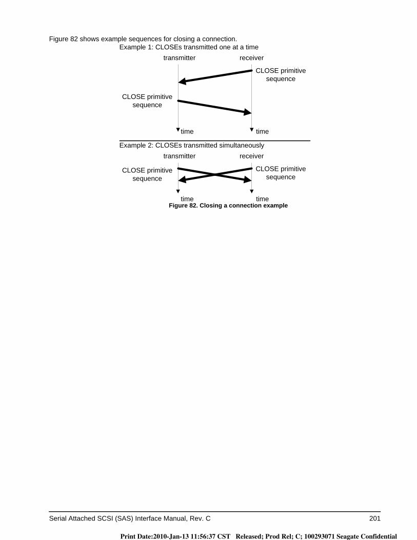
Serial Attached SCSI (SAS) Interface Manual, Rev. C 201
Figure 82 shows example sequences for closing a connection.
Figure 82. Closing a connection example
CLOSE primitive sequence
CLOSE primitive sequence
timetime
transmitter receiver
CLOSE primitive sequence
CLOSE primitive sequence
timetime
transmitter receiver
Example 2: CLOSEs transmitted simultaneously
Example 1: CLOSEs transmitted one at a time
Print Date:2010-Jan-13 11:56:37 CST Released; Prod Rel; C; 100293071 Seagate Confidential
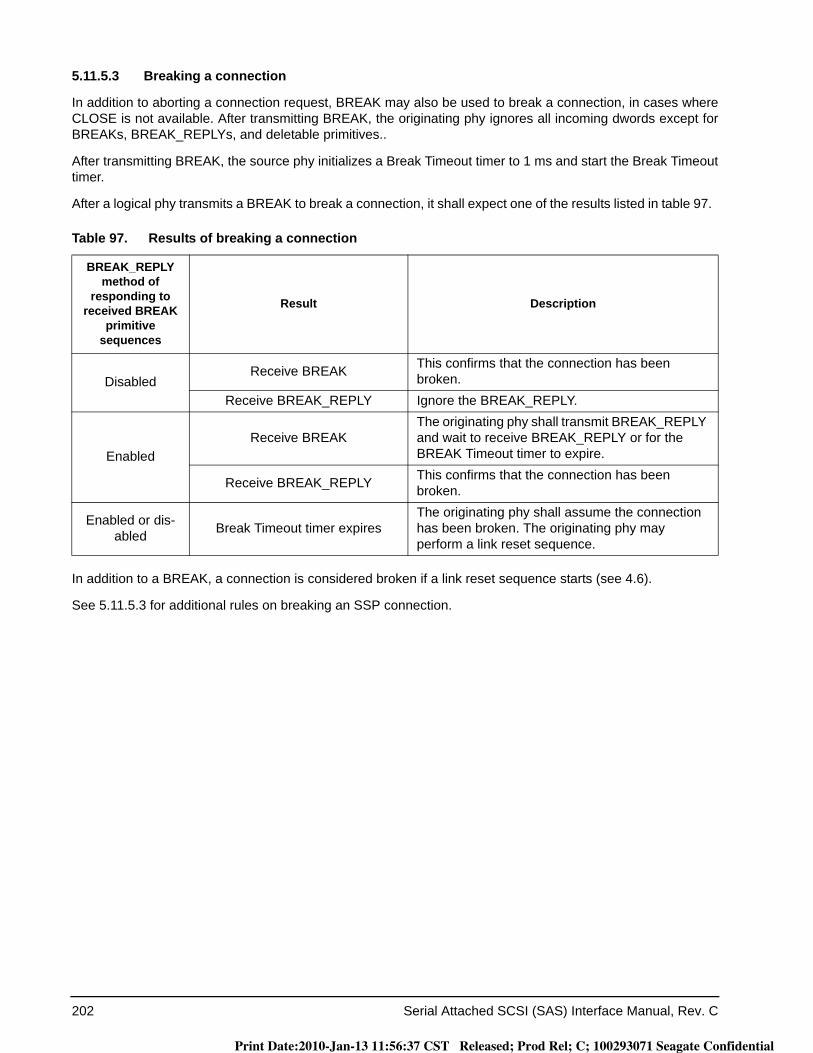
202 Serial Attached SCSI (SAS) Interface Manual, Rev. C
5.11.5.3 Breaking a connection
In addition to aborting a connection request, BREAK may also be used to break a connection, in cases where CLOSE is not available. After transmitting BREAK, the originating phy ignores all incoming dwords except for BREAKs, BREAK_REPLYs, and deletable primitives..
After transmitting BREAK, the source phy initializes a Break Timeout timer to 1 ms and start the Break Timeout timer.
After a logical phy transmits a BREAK to break a connection, it shall expect one of the results listed in table 97.
In addition to a BREAK, a connection is considered broken if a link reset sequence starts (see 4.6).
See 5.11.5.3 for additional rules on breaking an SSP connection.
Table 97. Results of breaking a connection
BREAK_REPLY method of
responding to received BREAK
primitive sequences
Result Description
DisabledReceive BREAK This confirms that the connection has been
broken.Receive BREAK_REPLY Ignore the BREAK_REPLY.
EnabledReceive BREAK
The originating phy shall transmit BREAK_REPLY and wait to receive BREAK_REPLY or for the BREAK Timeout timer to expire.
Receive BREAK_REPLY This confirms that the connection has been broken.
Enabled or dis-abled Break Timeout timer expires
The originating phy shall assume the connection has been broken. The originating phy may perform a link reset sequence.
Print Date:2010-Jan-13 11:56:37 CST Released; Prod Rel; C; 100293071 Seagate Confidential

Serial Attached SCSI (SAS) Interface Manual, Rev. C 203
5.11.6 Rate matching
Each successful connection request contains the connection rate (see 2.1.11) of the pathway.
Each logical phy in the pathway shall insert deletable primitives between dwords if its logical link rate is faster than the connection rate as described in table 98.
Deletable primitives inserted for rate matching are in addition to deletable primitives inserted for physical link rate tolerance management (see 5.3). See (SAS-2) for a summary of their combined requirements.
Every phy in the physical link inserts ALIGNs or NOTIFYs between dwords to match the connection rate. Phys receiving ALIGNs and NOTIFYs delete them regardless of whether the ALIGNs and NOTIFYs were inserted for clock skew management (see 5.3) or for rate matching.
The faster phy rotates between ALIGN (0), ALIGN (1), ALIGN (2), and ALIGN (3) to reduce long strings of repeated patterns appearing on the physical link. NOTIFYs may be used to replace ALIGNs (see 5.2.6.8).
Table 98. Rate matching deletable primitive insertion requirements
Logical link rate Connection rate Requirement
1.5 Gbps 1.5 Gbps None
3 Gbps1.5 Gbps
One deletable primitive within every 2 dwords that are not physical link rate toler-ance management deletable primitives (i.e., every overlapping window of 2 dwords)(e.g., a repeating pattern of a deletable primitive followed by a dword, or a repeating pattern of a dword followed by an deletable primitive)
3 Gbps None
6 Gbps
1.5 GbpsThree deletable primitives within every 4 dwords that are not physical link rate tol-erance management deletable primitives (i.e., 3 in every overlapping window of 4 dwords)
3 Gbps
One deletable primitive within every 2 dwords that are not physical link rate toler-ance management deletable primitives (i.e., every overlapping window of 2 dwords)(e.g., a repeating pattern of a deletable primitive followed by a dword, or a repeating pattern of a dword followed by an deletable primitive)
6 Gbps None
Print Date:2010-Jan-13 11:56:37 CST Released; Prod Rel; C; 100293071 Seagate Confidential
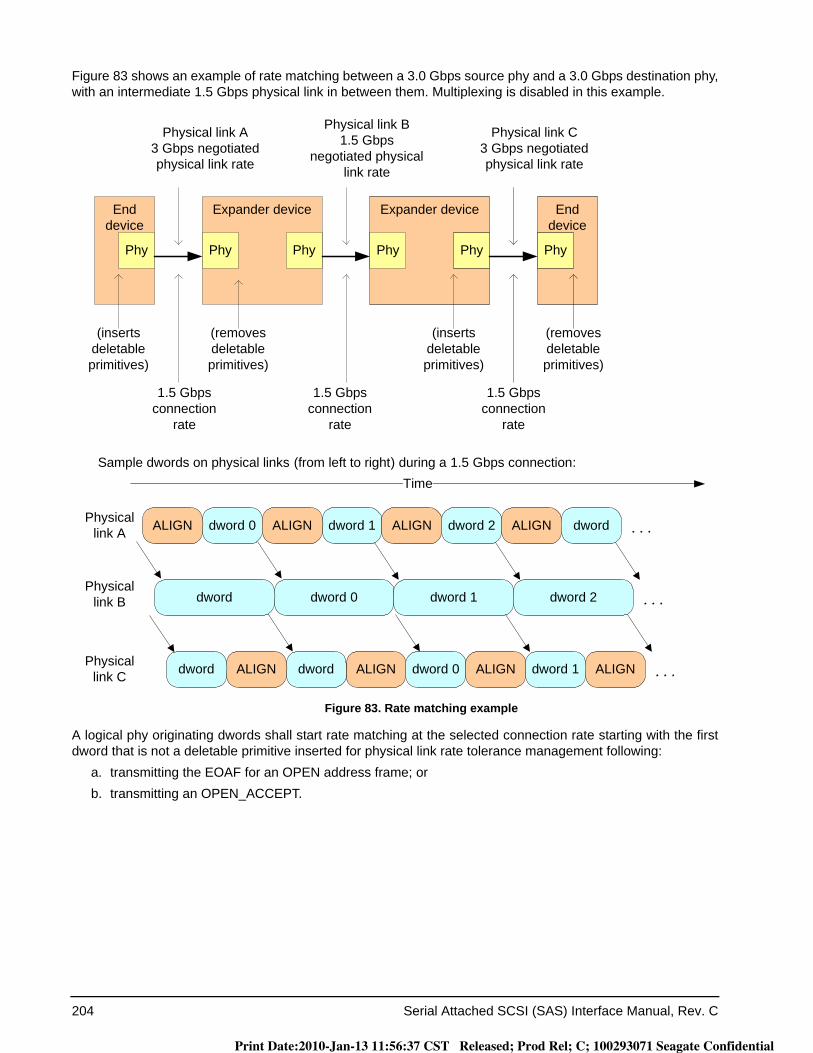
204 Serial Attached SCSI (SAS) Interface Manual, Rev. C
Figure 83 shows an example of rate matching between a 3.0 Gbps source phy and a 3.0 Gbps destination phy, with an intermediate 1.5 Gbps physical link in between them. Multiplexing is disabled in this example.
Figure 83. Rate matching example
A logical phy originating dwords shall start rate matching at the selected connection rate starting with the first dword that is not a deletable primitive inserted for physical link rate tolerance management following:
a. transmitting the EOAF for an OPEN address frame; orb. transmitting an OPEN_ACCEPT.
End device
End device
Physical link A3 Gbps negotiated physical link rate
Phy
Expander device
Phy Phy
Expander device
Phy Phy Phy
(inserts deletable primitives)
Physical link B1.5 Gbps
negotiated physical link rate
Physical link C3 Gbps negotiated physical link rate
(removes deletable primitives)
(inserts deletable primitives)
(removes deletable primitives)
1.5 Gbps connection
rate
1.5 Gbps connection
rate
1.5 Gbps connection
rate
dword 0
dword 0
ALIGN dword 1ALIGN
dword 1
Time
dword 0ALIGN dword 1ALIGN dword 2ALIGNPhysical link A
ALIGN
dword 2Physical
link B
Physical link C dwordALIGNdword
dword
ALIGN dword
Sample dwords on physical links (from left to right) during a 1.5 Gbps connection:
Print Date:2010-Jan-13 11:56:37 CST Released; Prod Rel; C; 100293071 Seagate Confidential
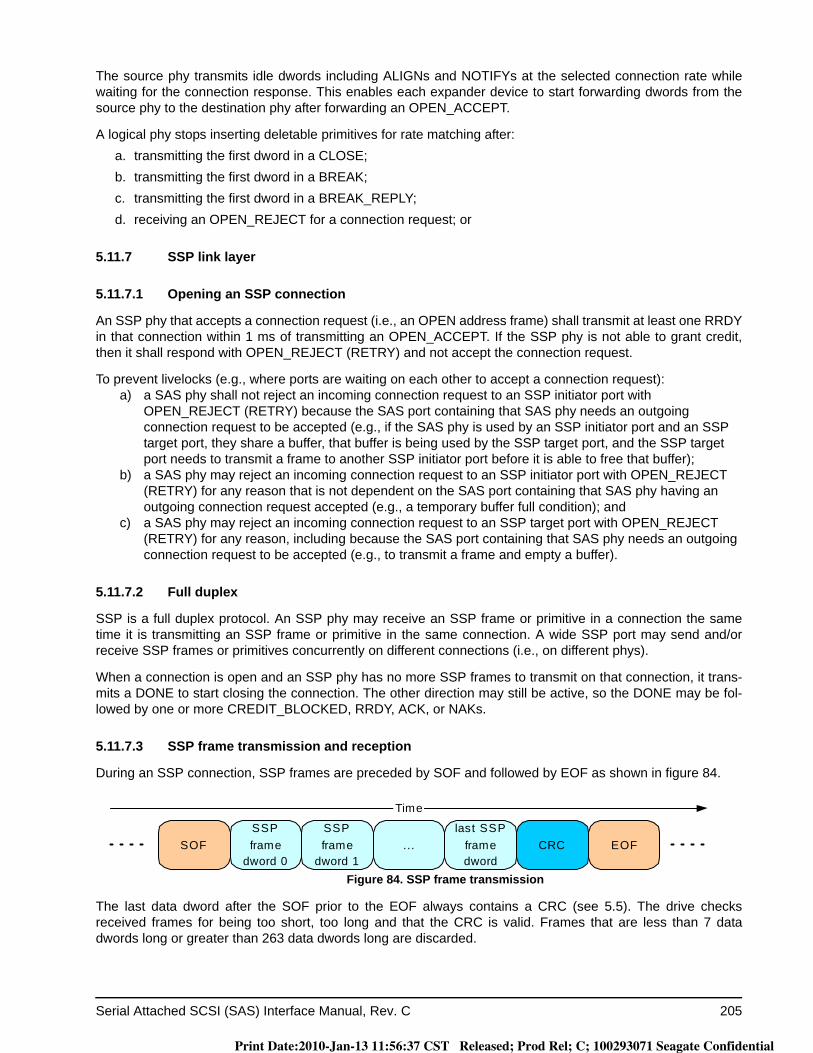
Serial Attached SCSI (SAS) Interface Manual, Rev. C 205
The source phy transmits idle dwords including ALIGNs and NOTIFYs at the selected connection rate while waiting for the connection response. This enables each expander device to start forwarding dwords from the source phy to the destination phy after forwarding an OPEN_ACCEPT.
A logical phy stops inserting deletable primitives for rate matching after:a. transmitting the first dword in a CLOSE;b. transmitting the first dword in a BREAK;c. transmitting the first dword in a BREAK_REPLY;d. receiving an OPEN_REJECT for a connection request; or
5.11.7 SSP link layer
5.11.7.1 Opening an SSP connection
An SSP phy that accepts a connection request (i.e., an OPEN address frame) shall transmit at least one RRDY in that connection within 1 ms of transmitting an OPEN_ACCEPT. If the SSP phy is not able to grant credit, then it shall respond with OPEN_REJECT (RETRY) and not accept the connection request.
To prevent livelocks (e.g., where ports are waiting on each other to accept a connection request):a) a SAS phy shall not reject an incoming connection request to an SSP initiator port with
OPEN_REJECT (RETRY) because the SAS port containing that SAS phy needs an outgoing connection request to be accepted (e.g., if the SAS phy is used by an SSP initiator port and an SSP target port, they share a buffer, that buffer is being used by the SSP target port, and the SSP target port needs to transmit a frame to another SSP initiator port before it is able to free that buffer);
b) a SAS phy may reject an incoming connection request to an SSP initiator port with OPEN_REJECT (RETRY) for any reason that is not dependent on the SAS port containing that SAS phy having an outgoing connection request accepted (e.g., a temporary buffer full condition); and
c) a SAS phy may reject an incoming connection request to an SSP target port with OPEN_REJECT (RETRY) for any reason, including because the SAS port containing that SAS phy needs an outgoing connection request to be accepted (e.g., to transmit a frame and empty a buffer).
5.11.7.2 Full duplex
SSP is a full duplex protocol. An SSP phy may receive an SSP frame or primitive in a connection the same time it is transmitting an SSP frame or primitive in the same connection. A wide SSP port may send and/or receive SSP frames or primitives concurrently on different connections (i.e., on different phys).
When a connection is open and an SSP phy has no more SSP frames to transmit on that connection, it trans-mits a DONE to start closing the connection. The other direction may still be active, so the DONE may be fol-lowed by one or more CREDIT_BLOCKED, RRDY, ACK, or NAKs.
5.11.7.3 SSP frame transmission and reception
During an SSP connection, SSP frames are preceded by SOF and followed by EOF as shown in figure 84.
Figure 84. SSP frame transmission
The last data dword after the SOF prior to the EOF always contains a CRC (see 5.5). The drive checks received frames for being too short, too long and that the CRC is valid. Frames that are less than 7 data dwords long or greater than 263 data dwords long are discarded.
SOFSSPframe
dword 0
SSPframe
dword 1... EOFCRC
last SSPframedword
Time
Print Date:2010-Jan-13 11:56:37 CST Released; Prod Rel; C; 100293071 Seagate Confidential

206 Serial Attached SCSI (SAS) Interface Manual, Rev. C
The drive acknowledges received SSP frames within 1 ms if not discarded with either:a) ACK (i.e., positive acknowledgement) if the SSP frame was received into a frame buffer without errors;
orb) NAK (CRC ERROR) (i.e., negative acknowledgement) if the SSP frame was received with a CRC error
(i.e., a bad CRC), an invalid dword, or an ERROR primitive.
Either the transport layer (see 7.2.5) retries sending SSP frames that encounter a link layer error (e.g., are NAKed or create an ACK/NAK timeout), or the SCSI application layer aborts the SCSI command associated with the SSP frame that encountered a link layer error.
5.11.7.4 SSP flow control
An SSP phy uses RRDY to grant credit for permission for the other SSP phy in the connection to transmit frames. Each RRDY increments credit by one frame. Frame transmission decrements credit by one frame. Credit of zero frames is established at the beginning of each connection.
SSP phys shall not increment credit past 255 frames.
To prevent deadlocks where an SSP initiator port and SSP target port are both waiting on each other to provide credit, an SSP initiator port shall not refuse to provide credit by withholding RRDY because it needs to transmit a frame itself. An SSP initiator port may refuse to provide credit for other reasons (e.g., temporary buffer full conditions).
An SSP target port may refuse to provide credit for any reason, including because it needs to transmit a frame itself.
If credit is zero, SSP phys that are going to be unable to provide credit for 1 ms may send CREDIT_BLOCKED. The other phy may use this to avoid waiting 1 ms to transmit DONE (CREDIT TIMEOUT).
If credit is nonzero, SSP phys that are going to be unable to provide additional credit for 1 ms, even if they receive frames per the existing credit, may transmit CREDIT_BLOCKED.
After sending CREDIT_BLOCKED, an SSP phy shall not transmit any additional RRDYs in the connection.
5.11.7.5 Interlocked frames
Table 99 shows indicates which SSP frames are interlocked and which are non-interlocked.
Before transmitting an interlocked frame, an SSP phy waits for all SSP frames to be acknowledged with ACK or NAK, even if credit is available. After transmitting an interlocked frame, an SSP phy does not transmit another SSP frame until it has been acknowledged with ACK or NAK, even if credit is available.
Table 99. SSP frame interlock requirements
SSP frame type Interlock requirement
COMMAND INTERLOCKED
TASK INTERLOCKED
XFER_RDY INTERLOCKED
DATA NON-INTERLOCKED
RESPONSE INTERLOCKED
Print Date:2010-Jan-13 11:56:37 CST Released; Prod Rel; C; 100293071 Seagate Confidential
Serial Attached SCSI (SAS) Interface Manual, Rev. C 207
Before transmitting a non-interlocked frame, an SSP phy waits for:a. all non-interlocked frames with different tags; andb. all interlocked frames;
to be acknowledged with ACK or NAK, even if credit is available.
After transmitting a non-interlocked frame, an SSP phy may transmit another non-interlocked frame with the same tag if credit is available. The phy does not transmit:
a. a non-interlocked frame with a different tag; orb. an interlocked frame;
until all SSP frames have been acknowledged with ACK or NAK, even if credit is available.
Interlocking does not prevent transmitting and receiving interlocked frames simultaneously (e.g., an SSP initia-tor phy could be transmitting a COMMAND frame while receiving XFER_RDY, DATA, or RESPONSE frames for a different command).
An SSP phy may transmit primitives responding to traffic it is receiving (e.g. an ACK or NAK to acknowledge an SSP frame, an RRDY to grant more receive credit, or a CREDIT_BLOCKED to indicate credit is not forthcom-ing) while waiting for an interlocked frame it transmitted to be acknowledged. These primitives may also be interspersed within an SSP frame.
Figure 85 shows an example of interlocked frame transmission.
Figure 85. Interlocked frames
Interlocked frame
Interlocked frame
ACK or NAK
ACK or NAK
transmitter receiver
timetime
Print Date:2010-Jan-13 11:56:37 CST Released; Prod Rel; C; 100293071 Seagate Confidential
208 Serial Attached SCSI (SAS) Interface Manual, Rev. C
Figure 86 shows an example of non-interlocked frame transmission with the same tags.
Figure 86. Non-interlocked frames with the same initiator port trasfer tag
Figure 87 shows an example of non-interlocked frame transmission with different tags.
Figure 87. Non-interlocked frames with different initiator port transfer tags
5.11.7.6 Breaking an SSP connection
In addition to the actions described in 5.11.5.3, the following shall be the responses by an SSP phy to a broken connection:
a) received frames having no CRC error may be considered valid regardless of whether an ACK has been transmitted in response to the frame prior to the broken connection;
b) transmitted frames for which an ACK has been received prior to a broken connection shall be considered successfully transmitted; and
c) transmitted frames for which an ACK or NAK has not been received prior to a broken connection shall be considered not successfully transmitted.
Non-interlocked frameNon-interlocked frameNon-interlocked frameNon-interlocked frame
Non-interlocked frameNon-interlocked frame
ACK or NAKACK or NAK
ACK or NAKACK or NAKACK or NAKACK or NAK
All non-interlocked
frames in this example have
the same initiator port transfer tag
transmitter receiver
timetime
Non-interlocked frame initiator port transfer tag A
ACK or NAKACK or NAK
Non-interlocked frame initiator port transfer tag B
Non-interlocked frame initiator port transfer tag C
ACK or NAKACK or NAKACK or NAKACK or NAK
ACK or NAK
Non-interlocked frame initiator port transfer tag C
Non-interlocked frame initiator port transfer tag ANon-interlocked frame initiator port transfer tag ANon-interlocked frame initiator port transfer tag A
Non-interlocked frame initiator port transfer tag ANon-interlocked frame initiator port transfer tag A
timetime
transmitter receiver
Print Date:2010-Jan-13 11:56:37 CST Released; Prod Rel; C; 100293071 Seagate Confidential
Serial Attached SCSI (SAS) Interface Manual, Rev. C 209
5.11.7.7 Closing an SSP connection
DONE is exchanged prior to closing an SSP connection. There are several versions of the DONE primitive indicating additional information about why the SSP connection is being closed:
a. DONE (NORMAL) indicates normal completion; the transmitter has no more SSP frames to transmit;b. DONE (CREDIT TIMEOUT) indicates the transmitter still has SSP frames to transmit, but did not receive
an RRDY granting frame credit within 1 ms; andc. DONE (ACK/NAK TIMEOUT) indicates the transmitter transmitted an SSP frame but did not receive the
corresponding ACK or NAK within 1 ms. As a result, the ACK/NAK count is not balanced and the trans-mitter is going to transmit a BREAK in 1 ms unless the recipient replies with DONE and the connection is closed.
After transmitting DONE, the transmitting phy initializes and starts a 1 ms DONE Timeout timer.
After transmitting DONE, the transmitting phy shall not transmit any additional frames during this connection. However, the phy may transmit ACK, NAK, RRDY, and CREDIT_BLOCKED after transmitting DONE if the other phy is still transmitting SSP frames in the reverse direction. Once an SSP phy has both transmitted and received DONE, it closes the connection by transmitting CLOSE (NORMAL) (see 5.11.5.2).
Figure 88 shows the sequence for a closing an SSP connection.
Figure 88. Closing an SSP connection example
5.12 SL (link layer for SAS logical phys) state machines
The SL (link layer for SAS logical phys) state machines control connections, handling both connection requests (OPEN address frames), CLOSEs, and BREAKs. The SL state machines are as follows:
a) SL_RA (receive OPEN address frame) state machine (see SPL); andb) SL_CC (connection control) state machine (see SPL).
DONE
CLOSE primitive sequence
DONE
CLOSE primitive sequence
timetime
transmitter receiver
(ACK, NAK, RRDY, and CREDIT_BLOCKED may be
transmitted after the first DONE)
Print Date:2010-Jan-13 11:56:37 CST Released; Prod Rel; C; 100293071 Seagate Confidential
210 Serial Attached SCSI (SAS) Interface Manual, Rev. C
6.0 Port layer
6.1 Port layer overview
The port layer (PL) state machines interface with one or more SAS link layer state machines and one or more SSP, SMP, and STP transport layer state machines to establish port connections and disconnections. The port layer state machines also interpret or pass transmit data, receive data, commands, and confirmations. Refer-ence SPL for the definition of the port layer state machines.
Print Date:2010-Jan-13 11:56:37 CST Released; Prod Rel; C; 100293071 Seagate Confidential
Serial Attached SCSI (SAS) Interface Manual, Rev. C 211
7.0 Transport layer
7.1 Transport layer overview
The transport layer defines frame formats. Transport layer interfaces to the application layer and port layer and construct and parses frame contents. For SSP, the transport layer only receives frames from the port layer that are going to be ACKed by the link layer.
7.2 SSP transport layer
7.2.1 SSP frame format
Table 100 defines the SSP frame format.
Table 100. SSP frame format
Byte\Bit 7 6 5 4 3 2 1 0
0 FRAME TYPE
1 (MSB)HASHED DESTINATION SAS ADDRESS
3 (LSB)
4 Reserved
5 (MSB)HASHED SOURCE SAS ADDRESS
7 (LSB)
8 Reserved
9 Reserved
10 Reserved TLR CONTROLRETRY DATA
FRAMES
RETRANS-MIT
CHANGING DATA
POINTER
11 Reserved NUMBER OF FILL BYTES
12 Reserved
13Reserved
15
Print Date:2010-Jan-13 11:56:37 CST Released; Prod Rel; C; 100293071 Seagate Confidential

212 Serial Attached SCSI (SAS) Interface Manual, Rev. C
FRAME TYPE fieldTable 101 defines the FRAME TYPE field, which defines the format of the INFORMATION UNIT field.
HASHED DESTINATION SAS ADDRESS field The HASHED DESTINATION SAS ADDRESS field contains the hashed value (see 2.2.3) of the destination SAS address. The drive port compares the HASHED DESTINATION SAS ADDRESS field in received frames with its hashed value of the port’s Port Identifier. If the compare fails, the drive discards the frame.
16 (MSB)INITIATOR PORT TRANSFER TAG
17 (LSB)
18 (MSB)TARGET PORT TRANSFER TAG
19 (LSB)
20 (MSB)DATA OFFSET
23 (LSB)
24INFORMATION UNIT
m
Fill bytes, if needed
n - 3 (MSB)CRC
n (LSB)
Table 101. FRAME TYPE field
Code Name of frame Information unit OriginatorInformation
unit size(bytes)
Reference
01h DATA frame Data SSP initiator port or SSP target port 1 to 1 024 7.2.2.4
05h XFER_RDY frame Transfer ready SSP target port 12 7.2.2.3
06h COMMAND frame Command SSP initiator port 28 to 284 7.2.2.1
07h RESPONSE frame Response SSP target port 24 to 1 024 7.2.2.5
16h TASK frame Task management function SSP initiator port 28 7.2.2.2
F0h - FFh Vendor specific
All others Reserved
Table 100. SSP frame format
Byte\Bit 7 6 5 4 3 2 1 0
Print Date:2010-Jan-13 11:56:37 CST Released; Prod Rel; C; 100293071 Seagate Confidential
Serial Attached SCSI (SAS) Interface Manual, Rev. C 213
HASHED SOURCE SAS ADDRESS fieldThe HASHED SOURCE SAS ADDRESS field contains the hashed value of the source SAS address. The drive port com-pares the HASHED SOURCE SAS ADDRESS field in received frames with the HASHED SOURCE SAS ADDRESSreceived in the OPEN address frame for the connection. If the compare fails, the drive discards the frame. If the HASHED SOURCE SAS ADDRESS field doesn’t match for a Command or Task frame, the drive will send a Response frame with DATAPRES=RESONSE DATA, and a Response code of INVALID FRAME.
TLR CONTROL fieldTable 102 defines the TLR CONTROL field for COMMAND frames. The TLR CONTROL field is reserved for all other frame types.
If an SSP initiator port supports transport layer retries, then it shall set the TLR CONTROL field to 01b in each COMMAND frame that it sends unless it has determined that the I_T_L nexus does not support the TLR CON-TROL field.
If an SSP initiator port does not support transport layer retries, then it shall set the TLR CONTROL field to 10b in each COMMAND frame that it sends unless it has determined that the I_T_L nexus does not support the TLR CONTROL field.
An SSP initiator port determines that an I_T_L nexus does not support the TLR CONTROL field if it sends a COMMAND frame with the TLR CONTROL field set to 01b or 10b and receives a RESPONSE frame with the DATAPRES field set to RESPONSE_DATA and the RESPONSE CODE field set to 02h (i.e., INVALID FRAME). After determining that an I_T_L nexus does not support the TLR CONTROL field, the SSP initiator port shall set the TLR CONTROL field to 00b for subsequent COMMAND frames for that I_T_L nexus.
Note. Initiator ports compliant with previous versions of this manual always set the TLR CONTROL field to 00b.
Table 102. TLR CONTROL field for COMMAND frames
Code a Description
00b or 11b
The SSP target port shall use the TRANSPORT LAYER RETRIES bit in the Protocol-Specific Logical Unit mode page (see 8.1.4.3) to enable or disable transport layer retries for this command as follows:
a) if the TRANSPORT LAYER RETRIES bit is set to one, then the SSP target port shall set the RETRY DATA FRAMES bit to one in any XFER_RDY frames that the SSP target port transmits for this command; or
b) if the TRANSPORT LAYER RETRIES bit is set to zero, then the SSP target port shall set the RETRY DATA FRAMES bit to zero in any XFER_RDY frames that the SSP target port transmits for this command.
01b
The SSP target port may enable transport layer retries for this command.
If the SSP target port enables transport layer retries, then it shall set the RETRY DATA FRAMES bit to one in any XFER_RDY frames that it transmits for this command.
If the SSP target port does not enable transport layer retries, then it shall set the RETRY DATA FRAMES bit to zero in any XFER_RDY frames that it transmits for this command.
10b
The SSP target port shall:a) disable transport layer retries for this command; andb) set the RETRY DATA FRAMES bit to zero in any XFER_RDY frames that it transmits for
this command.
a If the SSP target port receives a non-zero value in the TLR CONTROL field and does not support non-zero values in the TLR CONTROL field, then it shall reply with a RESPONSE frame with the DATAPRES field set to RESPONSE_DATA and the RESPONSE CODE field set to 02h (i.e., INVALID FRAME).
Print Date:2010-Jan-13 11:56:37 CST Released; Prod Rel; C; 100293071 Seagate Confidential

214 Serial Attached SCSI (SAS) Interface Manual, Rev. C
Note. The TLR CONTROL SUPPORTED field in the Protocol-Specific Logical Unit Information VPD page (see 8.1.6) indicates if the SSP target port supports the TLR CONTROL field set to a non-zero value.
RETRY DATA FRAMES bitThe RETRY DATA FRAMES bit is set to one for XFER_RDY frames under the conditions defined in 7.2.4 and shall be set to zero for all other frame types. When set to one this bit specifies that the SSP initiator port may retry write DATA frames that fail.
RETRANSMIT bitThe RETRANSMIT bit is set to one for RESPONSE frames under certain conditions (see 7.2.2.5) and shall be set to zero for all other frame types. This bit indicates the frame is a retransmission after the SSP target port failed in its previous attempt to transmit the frame.
CHANGING DATA POINTER bitThe CHANGING DATA POINTER bit is set to one for DATA frames under the conditions defined in 7.2.4 and shall be set to zero for all other frame types. When set to one this bit specifies that the frame is a retransmission after the SSP target port failed in its previous attempt to transmit the frame or a subsequent frame and the DATA OFFSET field of the frame may not be sequentially increased from that of the previous frame.
NUMBER OF FILL BYTES field
The NUMBER OF FILL BYTES field indicates the number of fill bytes between the INFORMATION UNIT field and the CRC field. The NUMBER OF FILL BYTES field shall be set to zero for all frame types except DATA frames (i.e., all other frame types are already four-byte aligned).
TAG fieldThe TAG field contains a value that allows the SSP initiator port to establish a context for commands and task management functions.
For COMMAND and TASK frames, the SSP initiator port shall set the TAG field to a value that is unique for the I_T nexus established by the connection (see 5.11). An SSP initiator port shall not reuse the same tag when transmitting COMMAND or TASK frames to different LUNs in the same SSP target port; it may reuse a tag when transmitting frames to different SSP target ports. The TAG field in a COMMAND frame contains the tag defined in SAM-4. The TAG field in a TASK frame does not correspond to a SAM-4 tag, but corresponds to an SAM-4 association. The tag space used in the TAG fields is shared across COMMAND and TASK frames (e.g., if a tag is used for a COMMAND frame, it is not simultaneously used for a TASK frame).
For DATA, XFER_RDY, and RESPONSE frames, the drive sets the TAG field to the tag of the command or task manage-ment function to which the frame pertains.
TARGET PORT TRANSFER TAG fieldThe TARGET PORT TRANSFER TAG field is used by the drive port to establish a write data context when receiving DATA frames. The drive port sets the field in every XFER_RDY frame to a value that is unique for the L_Q portion of the I_T_L_Q nexus. The drive may set the Target Port Transfer Tag to any value when transmitting other frames.
SSP initiator ports set the TARGET PORT TRANSFER TAG field as follows:a. For each DATA frame that is sent in response to a XFER_RDY frame, the SSP initiator port sets the TARGET PORT
TRANSFER TAG field to the value that was in the corresponding XFER_RDY frame;b. For each DATA frame that is sent containing first burst data (see 7.2.2.4), the SSP initiator port sets the TARGET
PORT TRANSFER TAG field to FFFFh; andc. For frames other than DATA frames, the SSP initiator port sets the TARGET PORT TRANSFER TAG field to FFFFh.
For DATA frames, the DATA OFFSET field is described in 7.2.2.4. For all other frame types, the DATA OFFSET field is ignored.
INFORMATION UNIT fieldThe INFORMATION UNIT field contains the information unit, the format of which is defined by the FRAME TYPE field. The maximum size of the INFORMATION UNIT field is 1,024 bytes, making the maximum size of the frame 1,052 bytes (1,024 bytes of data + 24 bytes of header + 4 bytes of CRC).
Print Date:2010-Jan-13 11:56:37 CST Released; Prod Rel; C; 100293071 Seagate Confidential

Serial Attached SCSI (SAS) Interface Manual, Rev. C 215
Fill bytesFill bytes shall be included after the INFORMATION UNIT field so the CRC field is aligned on a four byte boundary. The number of fill bytes are indicated by the NUMBER OF FILL BYTES field. The contents of the fill bytes are vendor specific.
CRC fieldThe CRC field contains a CRC value (see 5.5) that is computed over the entire SSP frame prior to the CRC field including the fill bytes (i.e., all data dwords between the SOF and EOF). The CRC field is checked by the link layer (see 5.11.7), not the transport layer.
Print Date:2010-Jan-13 11:56:37 CST Released; Prod Rel; C; 100293071 Seagate Confidential

216 Serial Attached SCSI (SAS) Interface Manual, Rev. C
7.2.2 Information units
7.2.2.1 COMMAND frame - COMMAND information unit
The COMMAND frame is sent by an SSP initiator port to request that a command be processed by a device server in a logical unit.
Table 103 defines the Command information unit used in the COMMAND frame.
LOGICAL UNIT NUMBER fieldThe LOGICAL UNIT NUMBER field contains the address of the logical unit. Drives supported by this manual implement only logical unit zero. Except for Inquiry, Request Sense, and Reports LUNs, the drive returns a check condition, Illegal Request LUN Not Supported if the LOGICAL UNIT NUMBER field is not zero.
ENABLE FIRST BURST bit 0 An ENABLE FIRST BURST bit set to zero specifies that the SSP target port shall not expect first burst data for the
command (i.e., that the FIRST BURST SIZE field in the Disconnect-Reconnect mode page shall be ignored). 1 An ENABLE FIRST BURST bit set to one specifies that the SSP target port shall expect first burst data for the com-
mand as defined by the FIRST BURST SIZE field in the Disconnect-Reconnect mode page (see the SCSI Com-mands Reference Manual).
COMMAND PRIORITY fieldThe COMMAND PRIORITY field specifies the relative scheduling importance of a command with the TASK ATTRIBUTEfield set to 000b (i.e., SIMPLE) in relation to other commands already in the task set with SIMPLE task attributes (see SAM-4).
Table 103. COMMAND information unit
Byte\Bit 7 6 5 4 3 2 1 0
0 (MSB)LOGICAL UNIT NUMBER
7 (LSB)
8 Reserved
9ENABLE FIRST BURST
COMMAND PRIORITY TASK ATTRIBUTE
10 Reserved
11 ADDITIONAL CDB LENGTH (n dwords) Reserved
12CDB
27
28ADDITIONAL CDB BYTES
27+n× 4
Print Date:2010-Jan-13 11:56:37 CST Released; Prod Rel; C; 100293071 Seagate Confidential
Serial Attached SCSI (SAS) Interface Manual, Rev. C 217
TASK ATTRIBUTE fieldThe TASK ATTRIBUTE field is defined in table 104. The drive processes all commands as tagged.
ADDITONAL CDB LENGTH fieldThe ADDITONAL CDB LENGTH field contains the length in dwords (four bytes) of the ADDITONAL CDB field.
CDB field and ADDITONAL CDB BYTES fieldThe CDB field and ADDITONAL CDB BYTES field together contain the CDB to be interpreted by the addressed logical unit. Any bytes between the end of the CDB and the end of the two fields are ignored (e.g., a six-byte CDB occupies the first six bytes of the CDB field; the remaining ten bytes are ignored; and the ADDITONAL CDB BYTES field is not present).
The contents of the CDB are defined in the SCSI Commands Reference Manual.
7.2.2.2 TASK information unit
Table 105 defines the task management function IU. The TASK frame is sent by an SSP initiator port to request that a task management function be processed by a task manager in a logical unit.
Table 104. TASK ATTRIBUTE field
Code Task attribute Description
000b SIMPLERequests that the task be managed according to the rules for a simple task attri-bute (see SAM-4).
001b HEAD OF QUEUERequests that the task be managed according to the rules for a head of queue task attribute (see SAM-4).
010b ORDEREDRequests that the task be managed according to the rules for an ordered task attribute (see SAM-4).
011b Reserved
100b ACARequests that the task be managed according to the rules for an automatic con-tingent allegiance task attribute (see SAM-4).
101b-111b Reserved
Table 105. TASK information unit
Byte\Bit 7 6 5 4 3 2 1 0
0 (MSB)LOGICAL UNIT NUMBER
7 (LSB)
8 Reserved
9 Reserved
10 TASK MANAGEMENT FUNCTION
11 Reserved
12 (MSB)INITIATOR PORT TRANSPORT TAG OF TASK TO BE MANAGED
13 (LSB)
14Reserved
27
Print Date:2010-Jan-13 11:56:37 CST Released; Prod Rel; C; 100293071 Seagate Confidential

218 Serial Attached SCSI (SAS) Interface Manual, Rev. C
LOGICAL UNIT NUMBER fieldThe LOGICAL UNIT NUMBER field contains the address of the logical unit. The structure of the logical unit number field shall be as defined in SAM-4. If the addressed logical unit does not exist, the task manager returns a RESPONSE frame with the DATAPRES field set to RESPONSE_DATA and its RESPONSE CODE field set to INVALID LOGICAL UNIT.
TASK MANAGEMENT FUNCTION fieldTable 106 defines the TASK MANAGEMENT FUNCTION field.
Table 106. Task management functions
CodeTask
management function
Uses LOGICAL
UNIT NUMBER
field
Uses INITIATOR
PORT TRANSFER
TAG TO MANAGE
field
Description
01h ABORT TASK yes yes
The task manager shall perform the ABORT TASK task man-agement function with L set to the value of the LOGICAL UNIT NUMBER and Q set to the value of the INITIATOR PORT TRANSPORT TAG OF TASK TO BE MANAGED field (see SAM-4).
02h ABORT TASK SET yes no
The task manager shall perform the ABORT TASK SET task management function with L set to the value of the LOGICAL UNIT NUMBER field (see SAM-4).
04h CLEAR TASK SET yes no
The task manager shall perform the CLEAR TASK SET task management function with L set to the value of the LOGICAL UNIT NUMBER field (see SAM-4).
08h LOGICAL UNIT RESET yes no
The task manager shall perform the LOGICAL UNIT RESET task management function with L set to the value of the LOGI-CAL UNIT NUMBER field (see SAM-4).
10h I_T NEXUS RESET
no no The task manager shall perform the I_T NEXUS RESET task management function (see SAM-4).
20h Reserved a
40h CLEAR ACA yes noThe task manager shall perform the CLEAR ACA task man-agement function with L set to the value of the LOGICAL UNIT NUMBER field (see SAM-4).
80h QUERY TASK yes yes
The task manager shall perform the QUERY TASK task man-agement function with L set to the value of the LOGICAL UNIT NUMBER and Q set to the value of the INITIATOR PORT TRANSPORT TAG OF TASK TO BE MANAGED field (see SAM-4).
81h QUERY TASK SET
yes no The task manager shall perform the QUERY TASK SET task management function with L set to the value of the LOGICAL UNIT NUMBER (see SAM-4).
82h QUERY ASYN-CHRONOUS
EVENT
yes no The task manager shall perform the QUERY ASYNCHRO-NOUS EVENT task management function with L set to the value of the LOGICAL UNIT NUMBER field (see SAM-4).
All others Reserved
a The TARGET RESET task management function defined in SAM-4 is not supported.
Print Date:2010-Jan-13 11:56:37 CST Released; Prod Rel; C; 100293071 Seagate Confidential

Serial Attached SCSI (SAS) Interface Manual, Rev. C 219
TASK MANAGEMENT FUNCTION fieldIf TASK MANAGEMENT FUNCTION field contains a reserved or unsupported value, the task manager returns a RESPONSE frame with the DATA PRES field set to RESPONSE_DATA and its RESPONSE CODE field set to TASK MAN-AGEMENT FUNCTION NOT SUPPORTED.
If TASK MANAGEMENT FUNCTION field is set to ABORT TASK or QUERY TASK, the INITIATOR PORT TRANSPORT TAG OF TASK TO BE MANAGED field specifies the TAG value from the COMMAND frame that contained the task to be aborted or checked. For all other task management functions, the INITIATOR PORT TRANSPORT TAG OF TASK TO BE MANAGED field is ignored.
Print Date:2010-Jan-13 11:56:37 CST Released; Prod Rel; C; 100293071 Seagate Confidential

220 Serial Attached SCSI (SAS) Interface Manual, Rev. C
7.2.2.3 XFER_RDY information unit
Table 107 defines the transfer ready IU. The XFER_RDY frame is sent by an SSP target port to request write data from the SSP initiator port.
REQUESTED OFFSET fieldThe REQUESTED OFFSET field contains the application client buffer offset of the segment of write data the SSP initiator port may transmit to the logical unit (using DATA frames). The requested offset is a multiple of four (i.e., each DATA frame shall begin transferring data on a dword boundary). The drive sets the REQUESTED OFFSET field to zero for the first XFER_RDY frame of a command.
WRITE DATA LENGTH fieldTheWRITE DATA LENGTH field contains the number of bytes of write data the SSP initiator port may transmit to the logical unit (using DATA frames) from the application client buffer starting at the requested offset. The drive sets the WRITE DATA LENGTH field to a value greater than or equal to 00000001h. If the value in the MAXIMUM BURST SIZE field in the Dis-connect-Reconnect mode page is not zero, the drive sets the WRITE DATA LENGTH field to a value less than or equal to the value in the MAXIMUM BURST SIZE field.
Only the last XFER_RDY frame for a command may contain a WRITE DATA LENGTH field that is not divisible by four.
Table 107. XFER_RDY information unit
Byte\Bit 7 6 5 4 3 2 1 0
0 (MSB)REQUESTED OFFSET
3 (LSB)
4 (MSB)WRITE DATA LENGTH
7 (LSB)
8Reserved
11
Print Date:2010-Jan-13 11:56:37 CST Released; Prod Rel; C; 100293071 Seagate Confidential
Serial Attached SCSI (SAS) Interface Manual, Rev. C 221
7.2.2.4 DATA information unit
Table 108 defines the data IU. The DATA frame is sent by an SSP initiator port to deliver write data and is sent by an SSP target port to deliver read data. The maximum size of the data IU is the maximum size of any IU in an SSP frame (see 7.2.1). The minimum size of the data IU is one byte.
DATA fieldThe DATA field contains the read or write data.
An SSP initiator port shall only transmit a DATA frame to the drive in response to an XFER_RDY frame. The drive discards received data frames without an associated outstanding XFER_RDY.
The size of the DATA field (i.e., the data length) is determined by subtracting the following values from the DATA frame size (i.e., the number of bytes between SOF and EOF (see 5.11.7.3)) :
a) the number of bytes in frame header (i.e., 28);b) the number of bytes in the CRC field (i.e., 4); andc) the number of fill bytes, specified by the NUMBER OF FILL BYTES field in the frame header (see 7.2.1).
The maximum size of the DATA information unit (i.e., the DATA field) is the maximum size of any information unit in an SSP frame (see 7.2.1). The minimum size of the Data information unit is one byte.
If the value in the MAXIMUM BURT SIZE field on the Disconnect-Reconnect mode page is not zero, then the maximum amount of data that is transferred at one time by an SSP target port per I_T_L_Q nexus is limited by the value in the MAX-IMUM BURT SIZE field (see the SCSI Commands Reference Manual).
A write DATA frame shall only contain write data for a single XFER_RDY frame.
An SSP initiator port shall set the NUMBER OF FILL BYTES field to 00b in the frame header (see 7.2.1) in all write DATA frames that it transmits in response to an XFER_RDY frame except the last write DATA frame for that XFER_RDY frame. An SSP initiator port may set the NUMBER OF FILL BYTES field to a non-zero value in the last DATA frame that it trans-mits in response to an XFER_RDY.
Note. Combined with the restrictions on the WRITE DATA LENGTH field in the XFER_RDY frame (see 7.2.2.3), this ensures that only the last write DATA frame for a command may have data with a length that is not a multiple of four).
An SSP target port shall set the NUMBER OF FILL BYTES field to 00b in the frame header (see 7.2.1) in all read DATA frames for a command except the last read DATA frame for that command. The SSP target port may set the NUMBER OF FILL BYTES field to a non-zero value in the last read DATA frame for a command (i.e., only the last read DATA frame for a command may contain data with a length that is not a multiple of four).
An SSP initiator port shall not transmit a write DATA frame for a given I_T_L_Q nexus after it has sent a TASK frame that terminates that command (e.g., an ABORT TASK).
The DATA OFFSET field in the frame header (see 7.2.1) contains the application client buffer offset as described by SAM-4. For read DATA frames, this is the offset into the application client’s data-in buffer; for write DATA frames, this is the offset into the application client’s data-out buffer. The data offset shall be a multiple of four (i.e., each DATA frame shall transfer data beginning on a dword boundary).
The DATA OFFSET field shall be set to 00000000h in the initial read DATA frame for a command. If any additional read DATA frames are required for the command and transport layer retries are not being used, then the DATA OFFSET field shall be set to the sum of the data offset and data length of the previous read DATA frame.
The DATA OFFSET field shall be set to 00000000h in the initial write DATA frame for a command. If any additional write DATA frames are required for the command and transport layer retries are not being used, then the DATA OFFSET field shall be set to the sum of the data offset and data length of the previous write DATA frame.
The value in the DATA OFFSET field plus the size of the DATA field shall not be greater than 1_00000000h (i.e., a SCSI command shall not transfer more than 232 bytes of write data and/or more than 232 bytes of read data).
Table 108. DATA information unit
Byte\Bit 7 6 5 4 3 2 1 0
0DATA
n
Print Date:2010-Jan-13 11:56:37 CST Released; Prod Rel; C; 100293071 Seagate Confidential
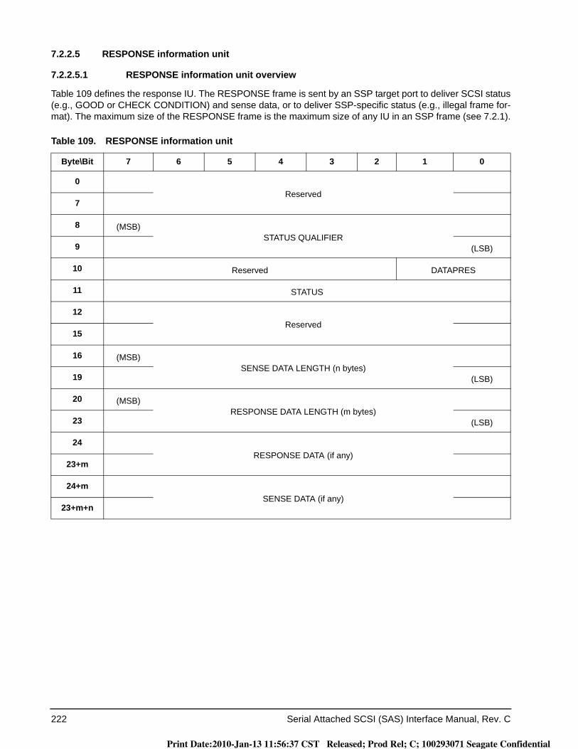
222 Serial Attached SCSI (SAS) Interface Manual, Rev. C
7.2.2.5 RESPONSE information unit
7.2.2.5.1 RESPONSE information unit overview
Table 109 defines the response IU. The RESPONSE frame is sent by an SSP target port to deliver SCSI status (e.g., GOOD or CHECK CONDITION) and sense data, or to deliver SSP-specific status (e.g., illegal frame for-mat). The maximum size of the RESPONSE frame is the maximum size of any IU in an SSP frame (see 7.2.1).
Table 109. RESPONSE information unit
Byte\Bit 7 6 5 4 3 2 1 0
0Reserved
7
8 (MSB)STATUS QUALIFIER
9 (LSB)
10 Reserved DATAPRES
11 STATUS
12Reserved
15
16 (MSB)SENSE DATA LENGTH (n bytes)
19 (LSB)
20 (MSB)RESPONSE DATA LENGTH (m bytes)
23 (LSB)
24RESPONSE DATA (if any)
23+m
24+mSENSE DATA (if any)
23+m+n
Print Date:2010-Jan-13 11:56:37 CST Released; Prod Rel; C; 100293071 Seagate Confidential

Serial Attached SCSI (SAS) Interface Manual, Rev. C 223
DATAPRES field
Table 110 defines the DATAPRES field, which indicates the format and content of the STATUS field,SENSE DATA LENGTH field, RESPONSE DATA LENGTH field, RESPONSE DATA field, and SENSE DATA field.
The drive returns a RESPONSE frame with the DATAPRES field set to NO_DATA if a command completes without sense data to return.
The drive returns a RESPONSE frame with the DATAPRES field set to RESPONSE_DATA in response to every TASK frame and in response to errors that occur while the transport layer is processing a COMMAND frame.
The drive returns a RESPONSE frame with the DATAPRES field set to SENSE_DATA if a command completes with sense data to return (e.g., CHECK CONDITION status).
If the DATAPRES field is set to a reserved value, then the SSP initiator port discards the RESPONSE frame.
7.2.2.5.2 RESPONSE information unit NO_DATA format
If the DATAPRES field is set to NO_DATA, then:a) the STATUS field contains the status code for a command that has ended (see the SCSI Commands
Reference Manual);b) the SSP target port shall set the STATUS QUALIFIER field to the status qualifier for the command (see
SAM-4);c) the SENSE DATA LENGTH field and the RESPONSE DATA LENGTH field are set to zero and ignored
by the SSP initiator port; andd) the SENSE DATA field and the RESPONSE DATA field are not present.
7.2.2.5.3 RESPONSE information unit RESPONSE_DATA format
If the DATAPRES field is set to RESPONSE_DATA, then:a) the STATUS field and the SENSE DATA LENGTH field are set to zero and ignored by the SSP initiator
port;b) the SENSE DATA field is not present;c) the RESPONSE DATA LENGTH field is set to four; andd) the RESPONSE DATA field is present.
Table 110. DATAPRES field
Code Name Description Reference
00b NO DATA No data present 7.2.2.5.2
01b RESPONSE_DATA Response data present 7.2.2.5.3
10b SENSE_DATA Sense data present 7.2.2.5.4
11b Reserved
Print Date:2010-Jan-13 11:56:37 CST Released; Prod Rel; C; 100293071 Seagate Confidential
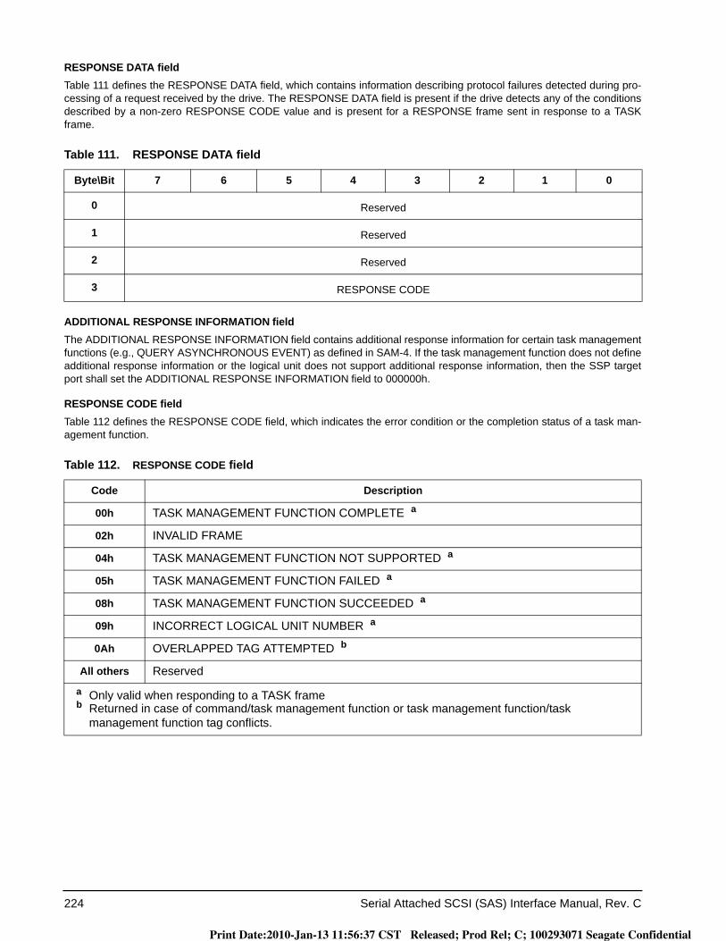
224 Serial Attached SCSI (SAS) Interface Manual, Rev. C
RESPONSE DATA fieldTable 111 defines the RESPONSE DATA field, which contains information describing protocol failures detected during pro-cessing of a request received by the drive. The RESPONSE DATA field is present if the drive detects any of the conditions described by a non-zero RESPONSE CODE value and is present for a RESPONSE frame sent in response to a TASK frame.
ADDITIONAL RESPONSE INFORMATION fieldThe ADDITIONAL RESPONSE INFORMATION field contains additional response information for certain task management functions (e.g., QUERY ASYNCHRONOUS EVENT) as defined in SAM-4. If the task management function does not define additional response information or the logical unit does not support additional response information, then the SSP target port shall set the ADDITIONAL RESPONSE INFORMATION field to 000000h.
RESPONSE CODE fieldTable 112 defines the RESPONSE CODE field, which indicates the error condition or the completion status of a task man-agement function.
Table 111. RESPONSE DATA field
Byte\Bit 7 6 5 4 3 2 1 0
0 Reserved
1 Reserved
2 Reserved
3 RESPONSE CODE
Table 112. RESPONSE CODE field
Code Description
00h TASK MANAGEMENT FUNCTION COMPLETE a
02h INVALID FRAME
04h TASK MANAGEMENT FUNCTION NOT SUPPORTED a
05h TASK MANAGEMENT FUNCTION FAILED a
08h TASK MANAGEMENT FUNCTION SUCCEEDED a
09h INCORRECT LOGICAL UNIT NUMBER a
0Ah OVERLAPPED TAG ATTEMPTED b
All others Reserveda Only valid when responding to a TASK frameb Returned in case of command/task management function or task management function/task
management function tag conflicts.
Print Date:2010-Jan-13 11:56:37 CST Released; Prod Rel; C; 100293071 Seagate Confidential
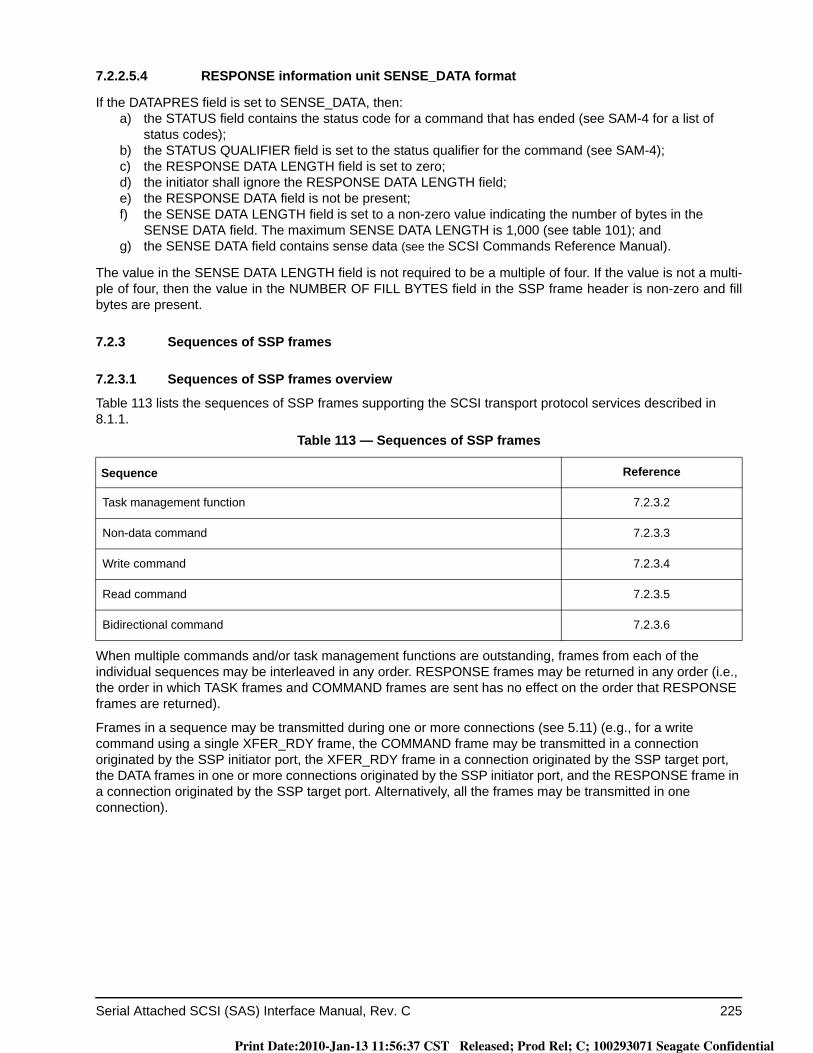
Serial Attached SCSI (SAS) Interface Manual, Rev. C 225
7.2.2.5.4 RESPONSE information unit SENSE_DATA format
If the DATAPRES field is set to SENSE_DATA, then:a) the STATUS field contains the status code for a command that has ended (see SAM-4 for a list of
status codes);b) the STATUS QUALIFIER field is set to the status qualifier for the command (see SAM-4);c) the RESPONSE DATA LENGTH field is set to zero; d) the initiator shall ignore the RESPONSE DATA LENGTH field;e) the RESPONSE DATA field is not be present;f) the SENSE DATA LENGTH field is set to a non-zero value indicating the number of bytes in the
SENSE DATA field. The maximum SENSE DATA LENGTH is 1,000 (see table 101); andg) the SENSE DATA field contains sense data (see the SCSI Commands Reference Manual).
The value in the SENSE DATA LENGTH field is not required to be a multiple of four. If the value is not a multi-ple of four, then the value in the NUMBER OF FILL BYTES field in the SSP frame header is non-zero and fill bytes are present.
7.2.3 Sequences of SSP frames
7.2.3.1 Sequences of SSP frames overview
Table 113 lists the sequences of SSP frames supporting the SCSI transport protocol services described in 8.1.1.
When multiple commands and/or task management functions are outstanding, frames from each of the individual sequences may be interleaved in any order. RESPONSE frames may be returned in any order (i.e., the order in which TASK frames and COMMAND frames are sent has no effect on the order that RESPONSE frames are returned).
Frames in a sequence may be transmitted during one or more connections (see 5.11) (e.g., for a write command using a single XFER_RDY frame, the COMMAND frame may be transmitted in a connection originated by the SSP initiator port, the XFER_RDY frame in a connection originated by the SSP target port, the DATA frames in one or more connections originated by the SSP initiator port, and the RESPONSE frame in a connection originated by the SSP target port. Alternatively, all the frames may be transmitted in one connection).
Table 113 — Sequences of SSP frames
Sequence Reference
Task management function 7.2.3.2
Non-data command 7.2.3.3
Write command 7.2.3.4
Read command 7.2.3.5
Bidirectional command 7.2.3.6
Print Date:2010-Jan-13 11:56:37 CST Released; Prod Rel; C; 100293071 Seagate Confidential
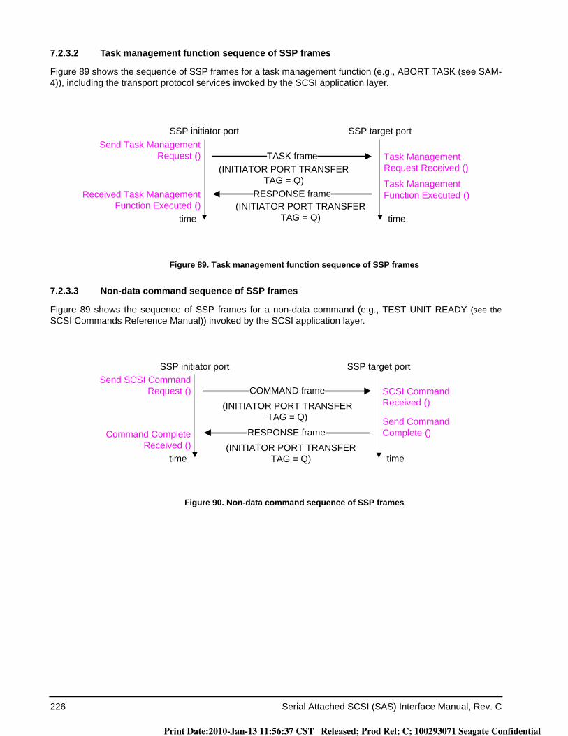
226 Serial Attached SCSI (SAS) Interface Manual, Rev. C
7.2.3.2 Task management function sequence of SSP frames
Figure 89 shows the sequence of SSP frames for a task management function (e.g., ABORT TASK (see SAM-4)), including the transport protocol services invoked by the SCSI application layer.
Figure 89. Task management function sequence of SSP frames
7.2.3.3 Non-data command sequence of SSP frames
Figure 89 shows the sequence of SSP frames for a non-data command (e.g., TEST UNIT READY (see the SCSI Commands Reference Manual)) invoked by the SCSI application layer.
Figure 90. Non-data command sequence of SSP frames
TASK frame
RESPONSE frame
SSP initiator port SSP target port
time time
Send Task Management Request () Task Management
Request Received ()
Received Task Management Function Executed ()
Task Management Function Executed ()
(INITIATOR PORT TRANSFER TAG = Q)
(INITIATOR PORT TRANSFER TAG = Q)
COMMAND frame
RESPONSE frame
SSP initiator port SSP target port
time time
Send SCSI Command Request () SCSI Command
Received ()
Command Complete Received ()
Send Command Complete ()
(INITIATOR PORT TRANSFER TAG = Q)
(INITIATOR PORT TRANSFER TAG = Q)
Print Date:2010-Jan-13 11:56:37 CST Released; Prod Rel; C; 100293071 Seagate Confidential
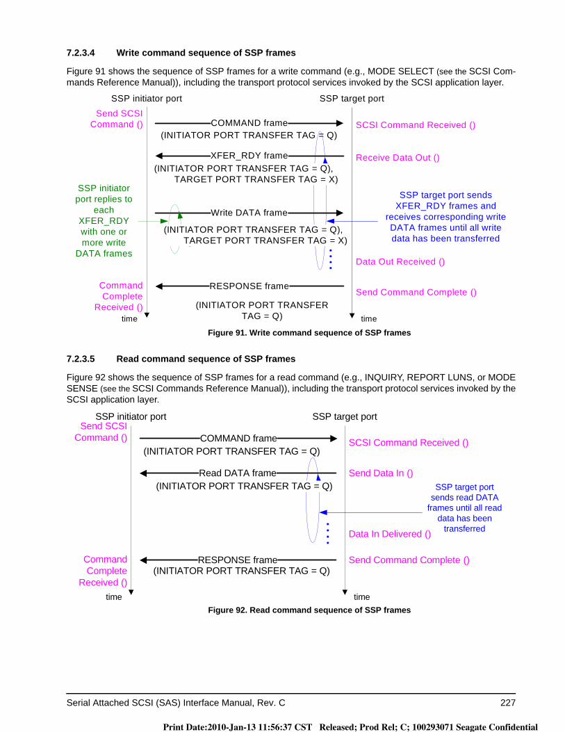
Serial Attached SCSI (SAS) Interface Manual, Rev. C 227
7.2.3.4 Write command sequence of SSP frames
Figure 91 shows the sequence of SSP frames for a write command (e.g., MODE SELECT (see the SCSI Com-mands Reference Manual)), including the transport protocol services invoked by the SCSI application layer.
Figure 91. Write command sequence of SSP frames
7.2.3.5 Read command sequence of SSP frames
Figure 92 shows the sequence of SSP frames for a read command (e.g., INQUIRY, REPORT LUNS, or MODE SENSE (see the SCSI Commands Reference Manual)), including the transport protocol services invoked by the SCSI application layer.
Figure 92. Read command sequence of SSP frames
COMMAND frame
SSP initiator port SSP target port
time time
Write DATA frame
RESPONSE frame
SSP initiator port replies to
each XFER_RDY with one or more write
DATA frames
SSP target port sends XFER_RDY frames and
receives corresponding write DATA frames until all write data has been transferred
Send SCSI Command () SCSI Command Received ()
Command Complete
Received ()Send Command Complete ()
Receive Data Out ()
Data Out Received ()
XFER_RDY frame
(INITIATOR PORT TRANSFER TAG = Q)
(INITIATOR PORT TRANSFER TAG = Q)
(INITIATOR PORT TRANSFER TAG = Q),TARGET PORT TRANSFER TAG = X)
(INITIATOR PORT TRANSFER TAG = Q),TARGET PORT TRANSFER TAG = X)
COMMAND frame
Read DATA frame
SSP initiator port SSP target port
time time
RESPONSE frame
SSP target port sends read DATA
frames until all read data has been
transferred
Send SCSI Command () SCSI Command Received ()
Command Complete
Received ()
Send Command Complete ()
Send Data In ()
Data In Delivered ()
(INITIATOR PORT TRANSFER TAG = Q)
(INITIATOR PORT TRANSFER TAG = Q)
(INITIATOR PORT TRANSFER TAG = Q)
Print Date:2010-Jan-13 11:56:37 CST Released; Prod Rel; C; 100293071 Seagate Confidential
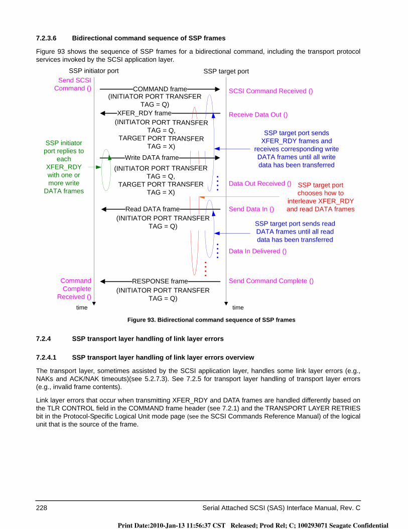
228 Serial Attached SCSI (SAS) Interface Manual, Rev. C
7.2.3.6 Bidirectional command sequence of SSP frames
Figure 93 shows the sequence of SSP frames for a bidirectional command, including the transport protocol services invoked by the SCSI application layer.
Figure 93. Bidirectional command sequence of SSP frames
7.2.4 SSP transport layer handling of link layer errors
7.2.4.1 SSP transport layer handling of link layer errors overview
The transport layer, sometimes assisted by the SCSI application layer, handles some link layer errors (e.g., NAKs and ACK/NAK timeouts)(see 5.2.7.3). See 7.2.5 for transport layer handling of transport layer errors (e.g., invalid frame contents).
Link layer errors that occur when transmitting XFER_RDY and DATA frames are handled differently based on the TLR CONTROL field in the COMMAND frame header (see 7.2.1) and the TRANSPORT LAYER RETRIESbit in the Protocol-Specific Logical Unit mode page (see the SCSI Commands Reference Manual) of the logical unit that is the source of the frame.
COMMAND frame
XFER_RDY frame
SSP initiator port SSP target port
time time
Write DATA frame
SSP initiator port replies to
each XFER_RDY with one or more write
DATA frames
SSP target port sends XFER_RDY frames and
receives corresponding write DATA frames until all write data has been transferred
Read DATA frame
SSP target port sends read DATA frames until all read data has been transferred
RESPONSE frame
SSP target port chooses how to
interleave XFER_RDY and read DATA frames
Send SCSI Command () SCSI Command Received ()
Command Complete
Received ()
Send Command Complete ()
Send Data In ()
Data Out Received ()
Data In Delivered ()
Receive Data Out ()
(INITIATOR PORT TRANSFER TAG = Q)
(INITIATOR PORT TRANSFER TAG = Q)
(INITIATOR PORT TRANSFER TAG = Q,
TARGET PORT TRANSFER TAG = X)
(INITIATOR PORT TRANSFER TAG = Q)
(INITIATOR PORT TRANSFER TAG = Q,
TARGET PORT TRANSFER TAG = X)
Print Date:2010-Jan-13 11:56:37 CST Released; Prod Rel; C; 100293071 Seagate Confidential
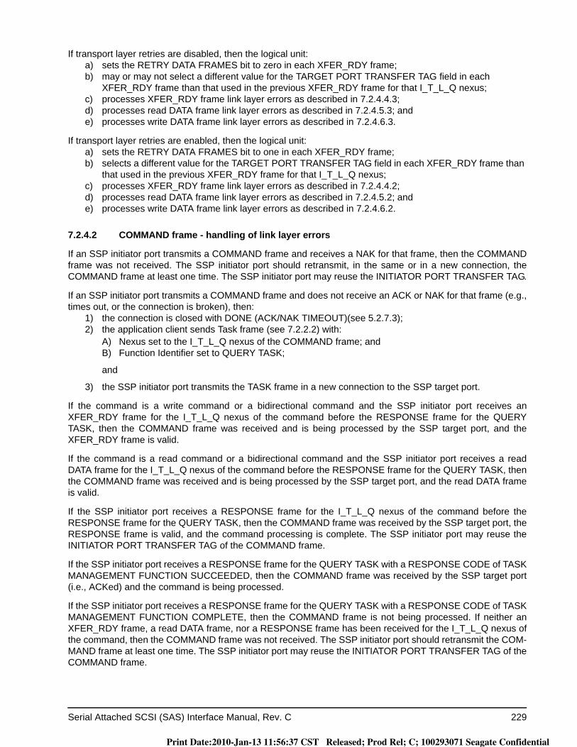
Serial Attached SCSI (SAS) Interface Manual, Rev. C 229
If transport layer retries are disabled, then the logical unit:a) sets the RETRY DATA FRAMES bit to zero in each XFER_RDY frame;b) may or may not select a different value for the TARGET PORT TRANSFER TAG field in each
XFER_RDY frame than that used in the previous XFER_RDY frame for that I_T_L_Q nexus;c) processes XFER_RDY frame link layer errors as described in 7.2.4.4.3;d) processes read DATA frame link layer errors as described in 7.2.4.5.3; ande) processes write DATA frame link layer errors as described in 7.2.4.6.3.
If transport layer retries are enabled, then the logical unit:a) sets the RETRY DATA FRAMES bit to one in each XFER_RDY frame;b) selects a different value for the TARGET PORT TRANSFER TAG field in each XFER_RDY frame than
that used in the previous XFER_RDY frame for that I_T_L_Q nexus;c) processes XFER_RDY frame link layer errors as described in 7.2.4.4.2;d) processes read DATA frame link layer errors as described in 7.2.4.5.2; ande) processes write DATA frame link layer errors as described in 7.2.4.6.2.
7.2.4.2 COMMAND frame - handling of link layer errors
If an SSP initiator port transmits a COMMAND frame and receives a NAK for that frame, then the COMMAND frame was not received. The SSP initiator port should retransmit, in the same or in a new connection, the COMMAND frame at least one time. The SSP initiator port may reuse the INITIATOR PORT TRANSFER TAG.
If an SSP initiator port transmits a COMMAND frame and does not receive an ACK or NAK for that frame (e.g., times out, or the connection is broken), then:
1) the connection is closed with DONE (ACK/NAK TIMEOUT)(see 5.2.7.3);2) the application client sends Task frame (see 7.2.2.2) with:
A) Nexus set to the I_T_L_Q nexus of the COMMAND frame; andB) Function Identifier set to QUERY TASK;
and
3) the SSP initiator port transmits the TASK frame in a new connection to the SSP target port.
If the command is a write command or a bidirectional command and the SSP initiator port receives an XFER_RDY frame for the I_T_L_Q nexus of the command before the RESPONSE frame for the QUERY TASK, then the COMMAND frame was received and is being processed by the SSP target port, and the XFER_RDY frame is valid.
If the command is a read command or a bidirectional command and the SSP initiator port receives a read DATA frame for the I_T_L_Q nexus of the command before the RESPONSE frame for the QUERY TASK, then the COMMAND frame was received and is being processed by the SSP target port, and the read DATA frame is valid.
If the SSP initiator port receives a RESPONSE frame for the I_T_L_Q nexus of the command before the RESPONSE frame for the QUERY TASK, then the COMMAND frame was received by the SSP target port, the RESPONSE frame is valid, and the command processing is complete. The SSP initiator port may reuse the INITIATOR PORT TRANSFER TAG of the COMMAND frame.
If the SSP initiator port receives a RESPONSE frame for the QUERY TASK with a RESPONSE CODE of TASK MANAGEMENT FUNCTION SUCCEEDED, then the COMMAND frame was received by the SSP target port (i.e., ACKed) and the command is being processed.
If the SSP initiator port receives a RESPONSE frame for the QUERY TASK with a RESPONSE CODE of TASK MANAGEMENT FUNCTION COMPLETE, then the COMMAND frame is not being processed. If neither an XFER_RDY frame, a read DATA frame, nor a RESPONSE frame has been received for the I_T_L_Q nexus of the command, then the COMMAND frame was not received. The SSP initiator port should retransmit the COM-MAND frame at least one time. The SSP initiator port may reuse the INITIATOR PORT TRANSFER TAG of the COMMAND frame.
Print Date:2010-Jan-13 11:56:37 CST Released; Prod Rel; C; 100293071 Seagate Confidential
230 Serial Attached SCSI (SAS) Interface Manual, Rev. C
7.2.4.3 TASK frame - handling of link layer errors
If an SSP initiator port transmits a TASK frame and receives a NAK for that frame, then the TASK frame was not received. The SSP initiator port should retransmit, in the same or in a new connection, the TASK frame at least one time with the RETRANSMIT bit set to one. The SSP initiator port may reuse the INITIATOR PORT TRANSFER TAG.
If an SSP initiator port transmits a TASK frame and does not receive an ACK or NAK for that frame (e.g., times out, or the connection is broken), then:
1) the connection is closed with DONE (ACK/NAK TIMEOUT) (see 5.2.7.3);2) the SSP initiator port transmits the TASK frame using the same INITIATOR PORT TRANSFER TAG
with the RETRANSMIT bit set to one in a new connection to the SSP target port.
If the SSP initiator port receives a RESPONSE frame for the TASK frame that arrives before the ACK or NAK for the TASK frame, then the TASK frame was received by the SSP target port (i.e., ACKed), the RESPONSE frame is valid, and the task management function is complete. The initiator port may reuse the INITIATOR PORT TRANSFER TAG of the TASK frame.
7.2.4.4 XFER_RDY frame - handling of link layer errors
7.2.4.4.1 XFER_RDY frame overview
If transport layer retries are enabled, then the SSP target port processes link layer errors that occur while trans-mitting XFER_RDY frames as described in 7.2.4.4.2.
If transport layer retries are disabled, then the SSP target port processes link layer errors that occur while transmitting XFER_RDY frames as described in 7.2.4.4.3.
7.2.4.4.2 XFER_RDY frame with transport layer retries enabled
If an SSP target port transmits an XFER_RDY frame and receives a NAK for that frame, then the SSP target port retransmits, in the same or a new connection, the XFER_RDY frame at least one time with:
a) a different value in the TARGET PORT TRANSFER TAG field;b) the RETRANSMIT bit set to one; andc) the other fields set to the same values as in the original XFER_RDY frame.
If an SSP target port transmits an XFER_RDY frame and does not receive an ACK or NAK for that frame (e.g., times out, or the connection is broken), then:
1) the connection is closed with DONE (ACK/NAK TIMEOUT) (see 5.2.7.3); and 2) the SSP target port retransmits, in a new connection, the XFER_RDY frame with:
A) the TARGET PORT TRANSFER TAG field set to a different value than in the original XFER_RDY frame;
B) the RETRANSMIT bit set to one; andC) the other fields set to the same values as in the original XFER_RDY frame.
If an SSP initiator port receives a new XFER_RDY frame with the RETRANSMIT bit set to one while process-ing the previous XFER_RDY frame for that I_T_L_Q nexus, then processing the previous XFER_RDY frame stops (i.e., stops transmitting write DATA frames) and starts servicing the new XFER_RDY frame. No write DATA frames for the previous XFER_RDY frame are transmitted after transmitting a write DATA frame for the new XFER_RDY frame.
The SSP target port may reuse the value in the TARGET PORT TRANSFER TAG field from the previous XFER_RDY frame after it receives a write DATA frame for the new XFER_RDY frame.
An SSP target port retransmits each XFER_RDY frame that does not receive an ACK or NAK at least one time.
The number of times an SSP target port retransmits each XFER_RDY frame is vendor-specific. When it reaches its vendor-specific limit, it follows the procedure for transport layer retries disabled described in 7.2.4.4.3.
Print Date:2010-Jan-13 11:56:37 CST Released; Prod Rel; C; 100293071 Seagate Confidential
Serial Attached SCSI (SAS) Interface Manual, Rev. C 231
7.2.4.4.3 XFER_RDY frame with transport layer retries disabled
If an SSP target port transmits an XFER_RDY frame and receives a NAK for that frame, then:1) the device server returns CHECK CONDITION status for that command with the sense key set to
ABORTED COMMAND and the additional sense code set to NAK RECEIVED (see SAS-2); and2) the SSP target port transmits the RESPONSE frame in the same or a new connection.
If an SSP target port transmits an XFER_RDY frame and does not receive an ACK or NAK for that frame (e.g., times out, or the connection is broken), then:
1) the connection is closed with DONE (ACK/NAK TIMEOUT)(see 5.2.7.3);2) the device server returns CHECK CONDITION status for that command with the sense key set to
ABORTED COMMAND and the additional sense code set to ACK/NAK TIMEOUT (see the SCSI Commands Reference Manual); and
3) the SSP target port transmits the RESPONSE frame in a new connection.
7.2.4.5 Read DATA frame - handling of link layer errors
7.2.4.5.1 Read DATA frame overview
If an SSP target port transmits a read DATA frame for a command with transport layer retries enabled, then the SSP target port processes link layer errors that occur while transmitting read DATA frames as described in 7.2.4.5.2.
If an SSP target port transmits a read DATA frame for a command with transport layer retries disabled, then the SSP target port processes link layer errors that occur while transmitting read DATA frames as described in 7.2.4.5.3.
7.2.4.5.2 Read DATA frame with transport layer retries enabled
If an SSP target port transmits a read DATA frame and receives a NAK for that frame, then the read DATA frame was not received. The SSP target port retransmits, in the same or in a new connection, all the read DATA frames for that I_T_L_Q nexus since a previous time when ACK/NAK balance occurred at least one time.
If an SSP target port transmits a read DATA frame and does not receive an ACK or NAK for that frame (e.g., times out, or the connection is broken), then:
1) the connection is closed with DONE (ACK/NAK TIMEOUT)(see 5.2.7.3); and2) the device server retransmits, in a new connection, all the read DATA frames for that I_T_L_Q nexus
since a previous time when ACK/NAK balance occurred at least one time.
The CHANGING DATA POINTER bit is set to one in the first retransmitted read DATA frame and the CHANG-ING DATA POINTER bit is set to zero in subsequent read DATA frames.
Each read DATA frame is retransmited that does not receive an ACK at least one time.
The number of times an SSP target port retransmits each read DATA frame is vendor-specific. When it reaches its vendor-specific limit, it follows the procedure for transport layer retries disabled described in 7.2.4.5.3.
7.2.4.5.3 Read DATA frame with transport layer retries disabled
If an SSP target port transmits a read DATA frame and receives a NAK for that frame, then:1) the device server returns CHECK CONDITION status for that command with the sense key set to
ABORTED COMMAND and the additional sense code set to NAK RECEIVED (see the SCSI Commands Reference Manual); and
2) the target port transmits the RESPONSE frame in the same or a new connection.
Print Date:2010-Jan-13 11:56:37 CST Released; Prod Rel; C; 100293071 Seagate Confidential

232 Serial Attached SCSI (SAS) Interface Manual, Rev. C
If an SSP target port transmits a read DATA frame and does not receive an ACK or NAK for that frame (e.g., times out, or the connection is broken), then:
1) the connection is closed with DONE (ACK/NAK TIMEOUT)(see 5.2.7.3);2) the device server returns CHECK CONDITION status for that command with the sense key set to
ABORTED COMMAND and the additional sense code set to ACK/NAK TIMEOUT (see the SCSI Commands Reference Manual); and
3) the target port transmits the RESPONSE frame in a new connection.
7.2.4.6 Write DATA frame - handling of link layer errors
7.2.4.6.1 Write DATA frame overview
An SSP initiator port processes link layer errors that occur while transmitting write DATA frames transmitted in response to an XFER_RDY frame that has its RETRY DATA FRAMES bit set to one as described in 7.2.4.6.2.
An SSP initiator port processes link layer errors that occur while transmitting write DATA frames in response to an XFER_RDY frame that has its RETRY DATA FRAMES bit set to zero as described in 7.2.4.6.3.
7.2.4.6.2 Write DATA frame with transport layer retries enabled
If an SSP initiator port transmits a write DATA frame and receives a NAK for that frame, then the write DATA frame was not received. All the write DATA frames for the previous XFER_RDY are retransmited.
If an SSP initiator port transmits a write DATA frame and does not receive an ACK or NAK for that frame (e.g., times out, or the connection is broken), then:
1) the connection is closed with DONE (ACK/NAK TIMEOUT)(see 5.2.7.3); and2) the device server retransmits, in a new connection, all the write DATA frames for the previous
XFER_RDY frame.
If that SSP initiator port receives a new XFER_RDY frame or a RESPONSE frame for the command while retransmitting or preparing to retransmit the write DATA frames, then the XFER_RDY frame or RESPONSE frame is processed and retransmitting the write DATA frames stops. Write DATA frames for the previous XFER_RDY frame are not transmitted after transmitting a write DATA frame in response to the new XFER_RDY frame.
The CHANGING DATA POINTER bit is set to one in the first retransmitted write DATA frame and the CHANG-ING DATA POINTER bit is set to zero in subsequent write DATA frames.
The devices server retransmits each write DATA frame that does not receive an ACK at least one time.
The number of times an SSP initiator port retransmits each write DATA frame is vendor-specific. When it reaches its vendor-specific limit, it follows the procedure for transport layer retries disabled described in 7.2.4.6.3.
7.2.4.6.3 Write DATA frame with transport layer retries disabled
If an SSP initiator port transmits a write DATA frame and does not receive an ACK or NAK for that frame (e.g., times out, or the connection is broken, then):
1) the connection is closed with DONE (ACK/NAK TIMEOUT)(see 5.2.7.3); and2) the application client aborts the command (see SAS-2).
If an SSP initiator port transmits a write DATA frame and receives a NAK for that frame, then the application cli-ent aborts the command (see SAS-2).
Print Date:2010-Jan-13 11:56:37 CST Released; Prod Rel; C; 100293071 Seagate Confidential

Serial Attached SCSI (SAS) Interface Manual, Rev. C 233
7.2.4.7 RESPONSE frame - handling of link layer errors
If an SSP target port transmits a RESPONSE frame and receives a NAK for that frame, then the target port retransmits, in the same or a new connection, the RESPONSE frame at least one time with the RETRANSMITbit set to one and with the other fields set to the same values as in the original RESPONSE frame.
If an SSP target port transmits a RESPONSE frame and does not receive an ACK or NAK for that frame (e.g., times out, or the connection is broken), then:
1) the connection closes with DONE (ACK/NAK TIMEOUT)(see 5.2.7.3); and2) the target port retransmits, in a new connection, the RESPONSE frame with:
A) the RETRANSMIT bit set to one; andB) the other fields set to the same values as in the original RESPONSE frame.
The device server retransmits each RESPONSE frame that does not receive an ACK at least one time. The number of times an SSP target port retransmits each RESPONSE frame is vendor-specific.
If an SSP initiator port receives a RESPONSE frame with a RETRANSMIT bit set to one, and it has previously received a RESPONSE frame for the same I_T_L_Q nexus, then the extra RESPONSE frame is discarded. If a previous RESPONSE frame for the I_T_L_Q nexus was not received, then it processes the RESPONSE frame.
7.2.5 SSP transport layer error handling summary
7.2.5.1 SSP transport layer error handling summary introduction
This subclause contains a summary of how SSP ports process transport layer errors. This summary does not include every error case. See 7.2.4 for transport layer handling of link layer errors (e.g., using transport layer retries).
7.2.5.2 SSP initiator port transport layer error handling summary
If an SSP initiator port receives a COMMAND or TASK frame or an unsupported frame type, the frame is dis-carded.
If an SSP initiator port receives an XFER_RDY, read DATA, or RESPONSE frame with an unknown INITIATOR PORT TRANSFER TAGINITIATOR PORT TRANSFER TAG field value, the frame is discarded. The applica-tion client may then abort the command with that INITIATOR PORT TRANSFER TAG.
If an SSP initiator port receives an XFER_RDY frame with a Transfer Ready information unit that is not 12 bytes long, the frame is discarded. The application client may then abort the command.
If an SSP initiator port receives an XFER_RDY frame in response to a command with no write data, then the frame is discarded, and the application client aborts the command (see SAS-2).
If an SSP initiator port receives an XFER_RDY frame requesting more write data than expected, then the frame is discarded, and the application client aborts the command (see SAS-2).
If an SSP initiator port receives an XFER_RDY frame requesting zero bytes, then the frame is discarded, and the application client aborts the command (see SAS-2).
If transport layer retries are disabled and an SSP initiator port receives an XFER_RDY frame with a requested offset that was not expected, the frame is discarded, and the application client aborts the command (see SAS-2).
If an SSP initiator port receives a read DATA frame in response to a command with no read data, the frame is discarded, and the application client aborts the command (see SAS-2).
Print Date:2010-Jan-13 11:56:37 CST Released; Prod Rel; C; 100293071 Seagate Confidential
234 Serial Attached SCSI (SAS) Interface Manual, Rev. C
If an SSP initiator port receives a read DATA frame with more read data than expected, the frame is discarded, and the application client aborts the command (see SAS-2). The SSP initiator port may receive a RESPONSE for the command before being able to abort the command.
If an SSP initiator port receives a read DATA frame with zero bytes, the frame is discarded, and the application client aborts the command (see SAS-2). The SSP initiator port may receive a RESPONSE for the command before being able to abort the command.
If transport layer retries are disabled and an SSP initiator port receives a read DATA frame with a data offset that was not expected, then that frame is discarded and any subsequent read DATA frames received for that command, and the application client aborts the command (see SAS-2). The SSP initiator port may receive a RESPONSE for the command before being able to abort the command.
If an SSP initiator port receives a RESPONSE frame that is not the correct length, then the command or task management function is considered completed with an error and discards the frame.
7.2.5.3 target port transport layer error handling summary
If an SSP target port receives an XFER_RDY or RESPONSE frame or another unsupported frame type, the frame discarded.
If an SSP target port receives a COMMAND frame and:a) the frame is too short to contain a LOGICAL UNIT NUMBER field;b) the frame is too short to contain a CDB;c) the ADDITIONAL CDB LENGTH field specifies that the frame should be a different length; ord) the TLR CONTROL field is set to a non-zero value and non-zero values are not supported,
then a RESPONSE frame is returned with the DATAPRES field set to RESPONSE_DATA and the RESPONSE CODE field set to INVALID FRAME.
If an SSP target port receives a TASK frame that is too short, a RESPONSE frame is returned with the DAT-APRES field set to RESPONSE_DATA and the RESPONSE CODE field set to INVALID FRAME.
If an SSP target port receives a COMMAND frame with an INITIATOR PORT TRANSFER TAG that is already in use for another command, then the device server may return CHECK CONDITION status with the sense key set to ABORTED COMMAND and the additional sense code set to OVERLAPPED COMMANDS ATTEMPTED (see SAS-2).
If an SSP target port receives:a) a COMMAND frame with an INITIATOR PORT TRANSFER TAG that is already in use for a task
management function; orb) a TASK frame with an INITIATOR PORT TRANSFER TAG that is already in use for a command or
another task management function,
then the task router and task manager(s) return a RESPONSE frame with the RESPONSE CODE field set to OVERLAPPED INITIATOR PORT TRANSFER TAG ATTEMPTED (see SAS-2).
If an SSP target port receives a write DATA frame with an unknown INITIATOR PORT TRANSFER TAG, the frame is discarded.
If an SSP target port receives a write DATA frame that does not contain first burst data and for which there is no XFER_RDY frame outstanding (i.e., it has received all requested write data), the frame is discarded.
If an SSP target port receives a TASK frame with an unknown logical unit number, a RESPONSE frame IS RETURNED with the DATAPRES field set to RESPONSE_DATA and the RESPONSE CODE field set to INCORRECT LOGICAL UNIT NUMBER (see SAS-2).
If an SSP target port receives a COMMAND frame or TASK frame with a TARGET PORT TRANSFER TAGfield set to a value other than FFFFh, then the SSP target may return a RESPONSE frame with the DAT-APRES field set to RESPONSE_DATA and the RESPONSE CODE field set to INVALID FRAME (see SAS-2).
Print Date:2010-Jan-13 11:56:37 CST Released; Prod Rel; C; 100293071 Seagate Confidential
Serial Attached SCSI (SAS) Interface Manual, Rev. C 235
If an SSP target port is using TARGET PORT TRANSFER TAGs and receives a write DATA frame with an unknown TARGET PORT TRANSFER TAG, the frame is discarded.
If transport layer retries are disabled and an SSP target port receives a write DATA frame with a data offset that was not expected, the frame is discarded, and the device server terminates the command with CHECK CON-DITION status with the sense key set to ABORTED COMMAND and the additional sense code set to DATA OFFSET ERROR (see SAS-2).
If an SSP target port receives a write DATA frame with more write data than expected (i.e., the write DATA frame contains data in excess of that requested by an XFER_RDY frame or, for first burst data, indicated by the FIRST BURST LENGTH field in the Disconnect-Reconnect mode page), the frame is discarded, and the device server terminates the command with CHECK CONDITION status with the sense key set to ABORTED COMMAND and the additional sense code set to TOO MUCH WRITE DATA (see SAS-2).
If an SSP target port receives a write DATA frame with zero bytes, the frame is discarded, and the device server terminates the command with CHECK CONDITION status with the sense key set to ABORTED COM-MAND and the additional sense code set to INFORMATION UNIT TOO SHORT (see SAS-2).
7.2.6 ST (transport layer for SSP ports) state machines overview
The ST state machines perform the following functions:a) receive and process transport protocol service requests and transport protocol service responses from
the SCSI application layer;b) receive and process other SAS connection management requests from the SCSI application layer;c) send transport protocol service indications and transport protocol service confirmations to the SCSI
application layer;d) send requests to the port layer to transmit frames and manage SAS connections; ande) receive confirmations from the port layer.
Reference SPL for the definition of the ST (transport layer for SSP ports) state machines.
7.3 STP transport layer
The STP transport layer is used by STP initiator ports to communicate with STP target ports in a SAS domain. Reference SPL for the definition of the STP protocol.
7.4 SMP transport layer
The SMP transport layer used by SMP initiator ports to communicate with SMP target ports in a SAS domain.Reference SPL for the definition of the SMP protocol.
Print Date:2010-Jan-13 11:56:37 CST Released; Prod Rel; C; 100293071 Seagate Confidential
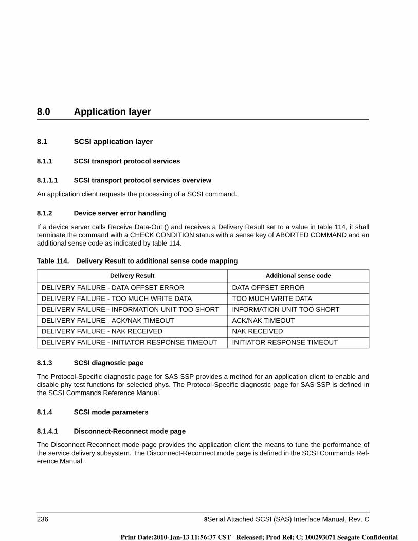
236 8Serial Attached SCSI (SAS) Interface Manual, Rev. C
8.0 Application layer
8.1 SCSI application layer
8.1.1 SCSI transport protocol services
8.1.1.1 SCSI transport protocol services overview
An application client requests the processing of a SCSI command.
8.1.2 Device server error handling
If a device server calls Receive Data-Out () and receives a Delivery Result set to a value in table 114, it shall terminate the command with a CHECK CONDITION status with a sense key of ABORTED COMMAND and an additional sense code as indicated by table 114.
8.1.3 SCSI diagnostic page
The Protocol-Specific diagnostic page for SAS SSP provides a method for an application client to enable and disable phy test functions for selected phys. The Protocol-Specific diagnostic page for SAS SSP is defined in the SCSI Commands Reference Manual.
8.1.4 SCSI mode parameters
8.1.4.1 Disconnect-Reconnect mode page
The Disconnect-Reconnect mode page provides the application client the means to tune the performance of the service delivery subsystem. The Disconnect-Reconnect mode page is defined in the SCSI Commands Ref-erence Manual.
Table 114. Delivery Result to additional sense code mapping
Delivery Result Additional sense code
DELIVERY FAILURE - DATA OFFSET ERROR DATA OFFSET ERRORDELIVERY FAILURE - TOO MUCH WRITE DATA TOO MUCH WRITE DATADELIVERY FAILURE - INFORMATION UNIT TOO SHORT INFORMATION UNIT TOO SHORTDELIVERY FAILURE - ACK/NAK TIMEOUT ACK/NAK TIMEOUTDELIVERY FAILURE - NAK RECEIVED NAK RECEIVEDDELIVERY FAILURE - INITIATOR RESPONSE TIMEOUT INITIATOR RESPONSE TIMEOUT
Print Date:2010-Jan-13 11:56:37 CST Released; Prod Rel; C; 100293071 Seagate Confidential

Serial Attached SCSI (SAS) Interface Manual, Rev. C 237
8.1.4.2 Protocol-Specific Port mode page
The Protocol-Specific Port mode page and subpages contains parameters that affect SSP target port opera-tion. The Protocol-Specific Port mode page and subpages are defined in the SCSI Commands Reference Man-ual.
8.1.4.3 Protocol-Specific Logical Unit mode page
The Protocol-Specific Logical Unit mode page contains parameters that affect SSP target port operation on behalf of the logical unit. The Protocol-Specific Logical Unit mode page is defined in the SCSI Commands Ref-erence Manual.
8.1.5 Protocol-Specific log page
The Protocol Specific log page for SAS defined in the SCSI Commands Reference Manual.
8.1.6 SCSI vital product data (VPD)
Each logical unit in a SAS target device that is a SCSI target device includes the identification descriptors listed in the SCSI Commands Reference Manual.
8.1.7 SCSI power conditions
The drive power condition states from the Power Condition mode page (see the SCSI Commands Reference Manual) and START STOP UNIT command (see the SCSI Commands Reference Manual), if implemented, shall interact with the NOTIFY (ENABLE SPINUP) primitive (see 5.2.5.3) to control temporary consumption of additional power (e.g., to spin up rotating media) as described in this subclause.
The drive uses NOTIFY (ENABLE SPINUP) to:
a) allow initial temporary consumption of additional power after power on;b) delay temporary consumption of additional power requested by START STOP UNIT commands; andc) delay temporary consumption of additional power after the Power Condition mode page standby
condition timer expires.
Reference SPL for definition of the Power Control (PC) state machine.
Print Date:2010-Jan-13 11:56:37 CST Released; Prod Rel; C; 100293071 Seagate Confidential

238 8Serial Attached SCSI (SAS) Interface Manual, Rev. C
Print Date:2010-Jan-13 11:56:37 CST Released; Prod Rel; C; 100293071 Seagate Confidential

Print Date:2010-Jan-13 11:56:37 CST Released; Prod Rel; C; 100293071 Seagate Confidential

Seagate Technology LLC920 Disc Drive, Scotts Valley, California 95066-4544, USAPublication Number: 100293071, Rev. C, Printed in USA
Print Date:2010-Jan-13 11:56:37 CST Released; Prod Rel; C; 100293071 Seagate Confidential