Embed Size (px)
Citation preview
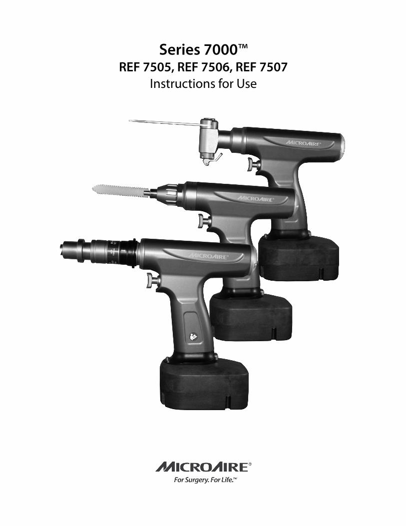
Series 7000™REF 7505, REF 7506, REF 7507
Instructions for Use
TABLE OF CONTENTS
Series 7000 Large-Power Battery System REF 7505, REF 7506, REF 7507
Instruction Manual
Intended Use and Introduction ................................................................1
General Warnings .......................................................................................1-3
Markings ........................................................................................................4-6
List of Compatible Accessories ..................................................................6
Environmental Parameters .........................................................................7
REF 7505 Drill Reamer Handpiece ........................................................7-9
REF 7506 Oscillating Saw Handpice ...............................................10-12
REF 7505 Reciprocating Saw Handpiece ......................................13-15
Series 7000 Battery Instructions ......................................................15-16
Drive Couplers ........................................................................................16-21
Instrument Cleaning and Sterilization Instructions ..................21-24
Warranty, Service and Repair .................................................................. 25
Troubleshooting ....................................................................................25-26
Electromagnetic Compatibility ........................................................27-28
1 IM-7505 Rev H
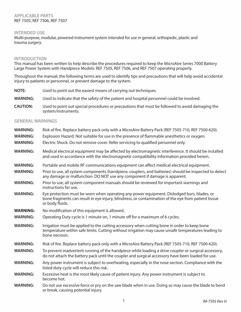
APPLICABLE PARTS REF 7505, REF 7506, REF 7507
INTENDED USEMulti-purpose, modular, powered instrument system intended for use in general, orthopedic, plastic and trauma surgery.
INTRODUCTIONThis manual has been written to help describe the procedures required to keep the MicroAire Series 7000 Battery Large Power System with Handpiece Models: REF 7505, REF 7506, and REF 7507 operating properly.
Throughout the manual, the following terms are used to identify tips and precautions that will help avoid accidental injury to patients or personnel, or prevent damage to the system.
NOTE: Used to point out the easiest means of carrying out techniques.
WARNING: Used to indicate that the safety of the patient and hospital personnel could be involved.
CAUTION: Used to point out special procedures or precautions that must be followed to avoid damaging the system/instruments.
GENERAL WARNINGS
WARNING: Risk of fire. Replace battery pack only with a MicroAire Battery Pack (REF 7505-710, REF 7500-620).WARNING: Explosion Hazard. Not suitable for use in the presence of flammable anesthetics or oxygen.WARNING: Electric Shock. Do not remove cover. Refer servicing to qualified personnel only.
WARNING: Medical electrical equipment may be affected by electromagnetic interference. It should be installed and used in accordance with the electromagnetic compatibility information provided herein.
WARNING: Portable and mobile RF communications equipment can affect medical electrical equipment.WARNING: Prior to use, all system components (handpiece, couplers, and batteries) should be inspected to detect
any damage or malfunction. DO NOT use any component if damage is apparent.WARNING: Prior to use, all system component manuals should be reviewed for important warnings and
instructions for use.WARNING: Eye protection must be worn when operating any power equipment. Dislodged burs, blades, or
bone fragments can result in eye injury, blindness, or contamination of the eye from patient tissue or body fluids.
WARNING: No modification of this equipment is allowed.WARNING: Operating Duty cycle is 1 minute on, 1 minute off for a maximum of 6 cycles.
WARNING: Irrigation must be applied to the cutting accessory when cutting bone in order to keep bone temperature within safe limits. Cutting without irrigation may cause unsafe temperatures leading to bone necrosis.
WARNING: Risk of fire. Replace battery pack only with a MicroAire Battery Pack (REF 7505-710, REF 7500-620).
WARNING: To prevent inadvertent running of the handpiece while loading a drive coupler or surgical accessory, do not attach the battery pack until the coupler and surgical accessory have been loaded for use.
WARNING: Any power instrument is subject to overheating, especially in the nose section. Compliance with the listed duty cycle will reduce this risk.WARNING: Excessive heat is the most likely cause of patient injury. Any power instrument is subject to become hot. WARNING: Do not use excessive force or pry on the saw blade when in use. Doing so may cause the blade to bend or break, causing potential injury.
2IM-7505 Rev H
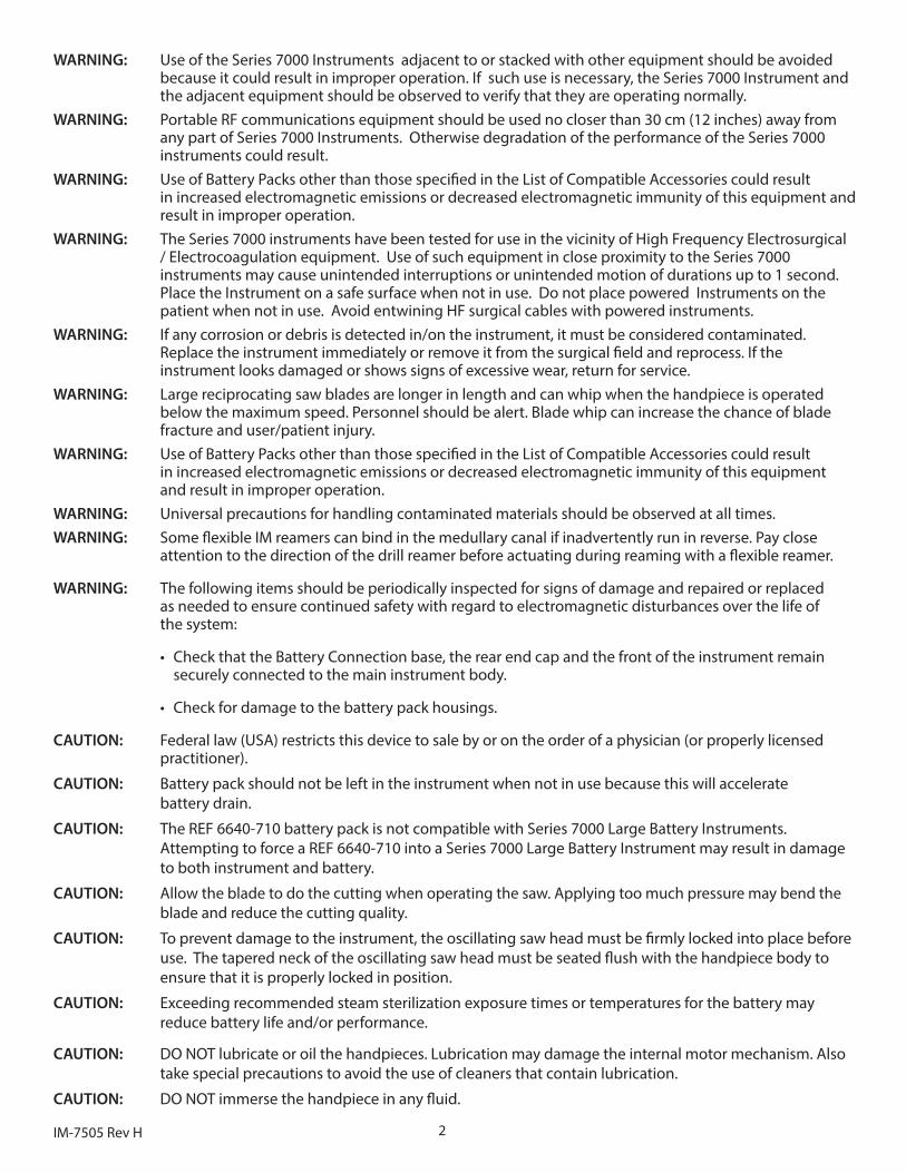
WARNING: Use of the Series 7000 Instruments adjacent to or stacked with other equipment should be avoided because it could result in improper operation. If such use is necessary, the Series 7000 Instrument and the adjacent equipment should be observed to verify that they are operating normally. WARNING: Portable RF communications equipment should be used no closer than 30 cm (12 inches) away from any part of Series 7000 Instruments. Otherwise degradation of the performance of the Series 7000 instruments could result. WARNING: Use of Battery Packs other than those specified in the List of Compatible Accessories could result in increased electromagnetic emissions or decreased electromagnetic immunity of this equipment and result in improper operation. WARNING: The Series 7000 instruments have been tested for use in the vicinity of High Frequency Electrosurgical / Electrocoagulation equipment. Use of such equipment in close proximity to the Series 7000 instruments may cause unintended interruptions or unintended motion of durations up to 1 second. Place the Instrument on a safe surface when not in use. Do not place powered Instruments on the patient when not in use. Avoid entwining HF surgical cables with powered instruments. WARNING: If any corrosion or debris is detected in/on the instrument, it must be considered contaminated. Replace the instrument immediately or remove it from the surgical field and reprocess. If the instrument looks damaged or shows signs of excessive wear, return for service. WARNING: Large reciprocating saw blades are longer in length and can whip when the handpiece is operated below the maximum speed. Personnel should be alert. Blade whip can increase the chance of blade fracture and user/patient injury. WARNING: Use of Battery Packs other than those specified in the List of Compatible Accessories could result in increased electromagnetic emissions or decreased electromagnetic immunity of this equipment and result in improper operation. WARNING: Universal precautions for handling contaminated materials should be observed at all times. WARNING: Some flexible IM reamers can bind in the medullary canal if inadvertently run in reverse. Pay close attention to the direction of the drill reamer before actuating during reaming with a flexible reamer.
WARNING: The following items should be periodically inspected for signs of damage and repaired or replaced as needed to ensure continued safety with regard to electromagnetic disturbances over the life of the system:
• Check that the Battery Connection base, the rear end cap and the front of the instrument remain securely connected to the main instrument body.
• Check for damage to the battery pack housings.
CAUTION: Federal law (USA) restricts this device to sale by or on the order of a physician (or properly licensed practitioner).
CAUTION: Battery pack should not be left in the instrument when not in use because this will accelerate battery drain.
CAUTION: The REF 6640-710 battery pack is not compatible with Series 7000 Large Battery Instruments. Attempting to force a REF 6640-710 into a Series 7000 Large Battery Instrument may result in damage to both instrument and battery.
CAUTION: Allow the blade to do the cutting when operating the saw. Applying too much pressure may bend the blade and reduce the cutting quality.
CAUTION: To prevent damage to the instrument, the oscillating saw head must be firmly locked into place before use. The tapered neck of the oscillating saw head must be seated flush with the handpiece body to ensure that it is properly locked in position.
CAUTION: Exceeding recommended steam sterilization exposure times or temperatures for the battery may reduce battery life and/or performance.
CAUTION: DO NOT lubricate or oil the handpieces. Lubrication may damage the internal motor mechanism. Also take special precautions to avoid the use of cleaners that contain lubrication.
CAUTION: DO NOT immerse the handpiece in any fluid.
3 IM-7505 Rev H
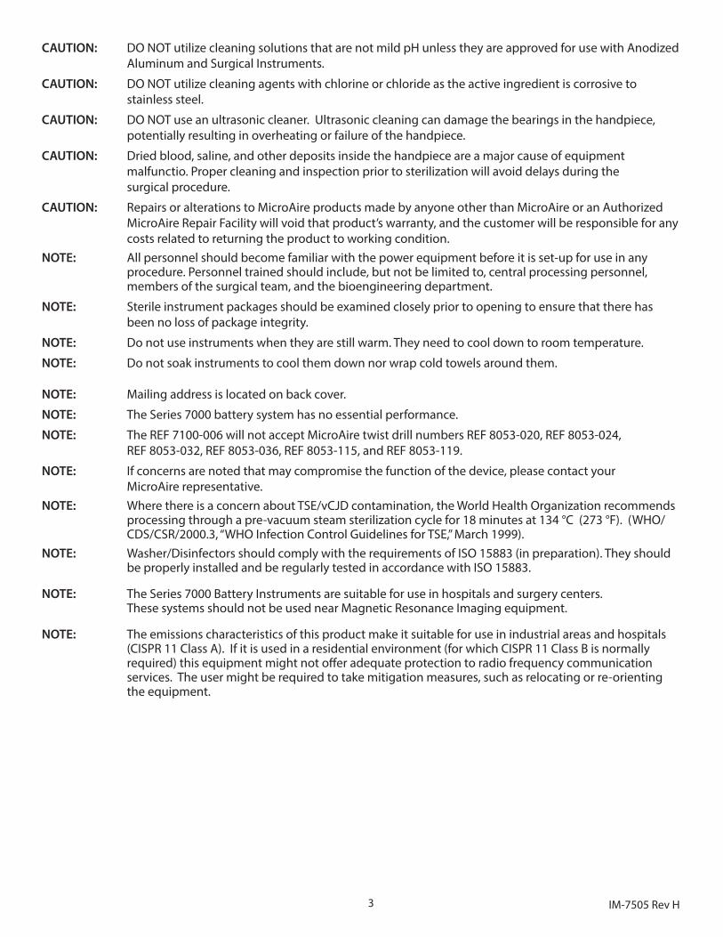
CAUTION: DO NOT utilize cleaning solutions that are not mild pH unless they are approved for use with Anodized Aluminum and Surgical Instruments.
CAUTION: DO NOT utilize cleaning agents with chlorine or chloride as the active ingredient is corrosive to stainless steel.
CAUTION: DO NOT use an ultrasonic cleaner. Ultrasonic cleaning can damage the bearings in the handpiece, potentially resulting in overheating or failure of the handpiece.
CAUTION: Dried blood, saline, and other deposits inside the handpiece are a major cause of equipment malfunctio. Proper cleaning and inspection prior to sterilization will avoid delays during the surgical procedure.
CAUTION: Repairs or alterations to MicroAire products made by anyone other than MicroAire or an Authorized MicroAire Repair Facility will void that product’s warranty, and the customer will be responsible for any costs related to returning the product to working condition.
NOTE: All personnel should become familiar with the power equipment before it is set-up for use in any procedure. Personnel trained should include, but not be limited to, central processing personnel, members of the surgical team, and the bioengineering department.
NOTE: Sterile instrument packages should be examined closely prior to opening to ensure that there has been no loss of package integrity.
NOTE: Do not use instruments when they are still warm. They need to cool down to room temperature.
NOTE: Do not soak instruments to cool them down nor wrap cold towels around them.
NOTE: Mailing address is located on back cover.
NOTE: The Series 7000 battery system has no essential performance.
NOTE: The REF 7100-006 will not accept MicroAire twist drill numbers REF 8053-020, REF 8053-024, REF 8053-032, REF 8053-036, REF 8053-115, and REF 8053-119.
NOTE: If concerns are noted that may compromise the function of the device, please contact your MicroAire representative.NOTE: Where there is a concern about TSE/vCJD contamination, the World Health Organization recommends processing through a pre-vacuum steam sterilization cycle for 18 minutes at 134 °C (273 °F). (WHO/ CDS/CSR/2000.3, “WHO Infection Control Guidelines for TSE,” March 1999). NOTE: Washer/Disinfectors should comply with the requirements of ISO 15883 (in preparation). They should be properly installed and be regularly tested in accordance with ISO 15883.
NOTE: The Series 7000 Battery Instruments are suitable for use in hospitals and surgery centers. These systems should not be used near Magnetic Resonance Imaging equipment.
NOTE: The emissions characteristics of this product make it suitable for use in industrial areas and hospitals (CISPR 11 Class A). If it is used in a residential environment (for which CISPR 11 Class B is normally required) this equipment might not offer adequate protection to radio frequency communication services. The user might be required to take mitigation measures, such as relocating or re-orienting the equipment.
4IM-7505 Rev H
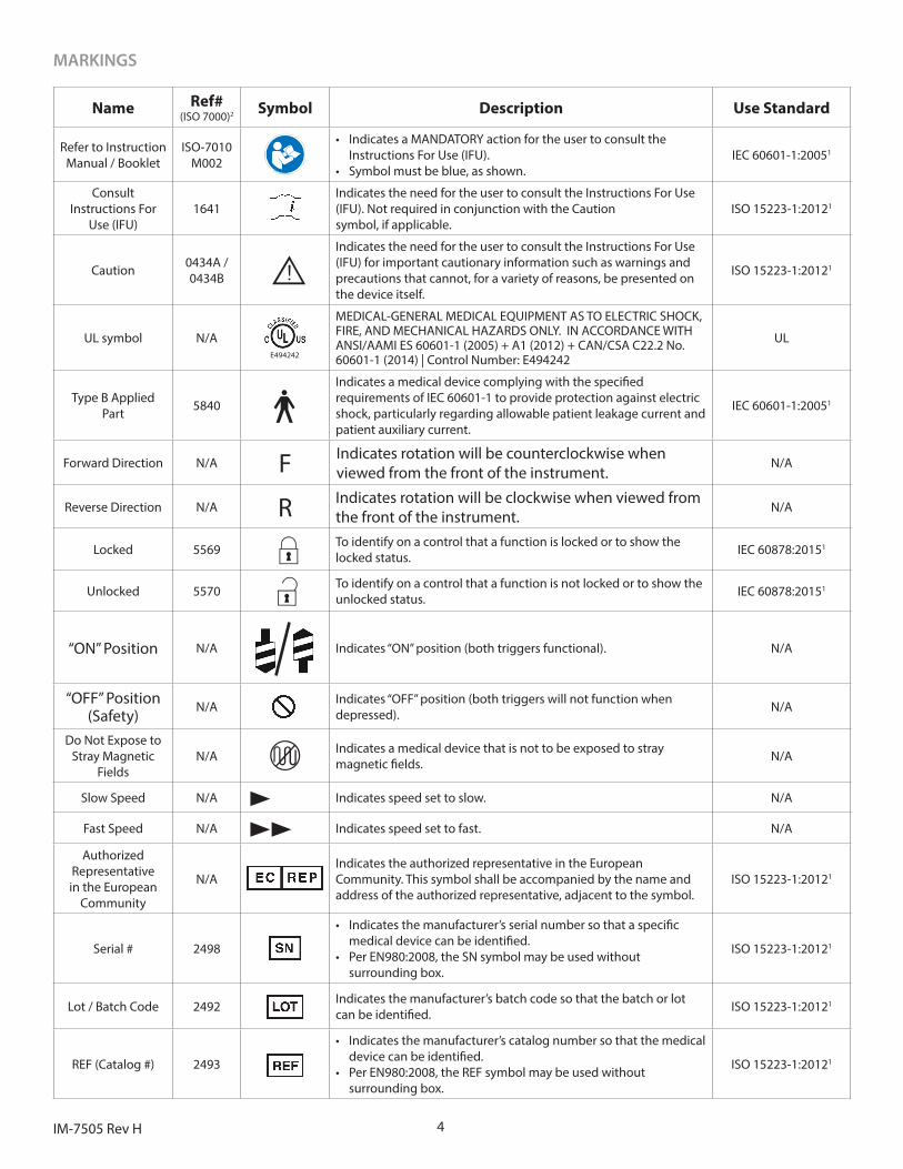
MARKINGS
Name Ref# (ISO 7000)2 Symbol Description Use Standard
Refer to Instruction Manual / Booklet
ISO-7010 M002
• Indicates a MANDATORY action for the user to consult the Instructions For Use (IFU).
• Symbol must be blue, as shown.IEC 60601-1:20051
Consult Instructions For
Use (IFU)1641
Indicates the need for the user to consult the Instructions For Use (IFU). Not required in conjunction with the Caution symbol, if applicable.
ISO 15223-1:20121
Caution 0434A /0434B C
Indicates the need for the user to consult the Instructions For Use (IFU) for important cautionary information such as warnings and precautions that cannot, for a variety of reasons, be presented on the device itself.
ISO 15223-1:20121
UL symbol N/AE494242
MEDICAL-GENERAL MEDICAL EQUIPMENT AS TO ELECTRIC SHOCK, FIRE, AND MECHANICAL HAZARDS ONLY. IN ACCORDANCE WITH ANSI/AAMI ES 60601-1 (2005) + A1 (2012) + CAN/CSA C22.2 No. 60601-1 (2014) | Control Number: E494242
UL
Type B AppliedPart 5840 B
Indicates a medical device complying with the specified requirements of IEC 60601-1 to provide protection against electricshock, particularly regarding allowable patient leakage current and patient auxiliary current.
IEC 60601-1:20051
Forward Direction N/A F Indicates rotation will be counterclockwise when viewed from the front of the instrument.
N/A
Reverse Direction N/A R Indicates rotation will be clockwise when viewed from the front of the instrument.
N/A
Locked 5569 To identify on a control that a function is locked or to show the locked status. IEC 60878:20151
Unlocked 5570 To identify on a control that a function is not locked or to show the unlocked status. IEC 60878:20151
“ON” Position N/A Indicates “ON” position (both triggers functional). N/A
“OFF” Position (Safety)
N/A Indicates “OFF” position (both triggers will not function when depressed). N/A
Do Not Expose to Stray Magnetic
FieldsN/A Indicates a medical device that is not to be exposed to stray
magnetic fields. N/A
Slow Speed N/A p Indicates speed set to slow. N/A
Fast Speed N/A pp Indicates speed set to fast. N/A
Authorized Representative in the European
Community
N/AIndicates the authorized representative in the European Community. This symbol shall be accompanied by the name and address of the authorized representative, adjacent to the symbol.
ISO 15223-1:20121
Serial # 2498
• Indicates the manufacturer’s serial number so that a specific medical device can be identified.
• Per EN980:2008, the SN symbol may be used without surrounding box.
ISO 15223-1:20121
Lot / Batch Code 2492 Indicates the manufacturer’s batch code so that the batch or lot can be identified. ISO 15223-1:20121
REF (Catalog #) 2493
• Indicates the manufacturer’s catalog number so that the medical device can be identified.
• Per EN980:2008, the REF symbol may be used without surrounding box.
ISO 15223-1:20121
5 IM-7505 Rev H
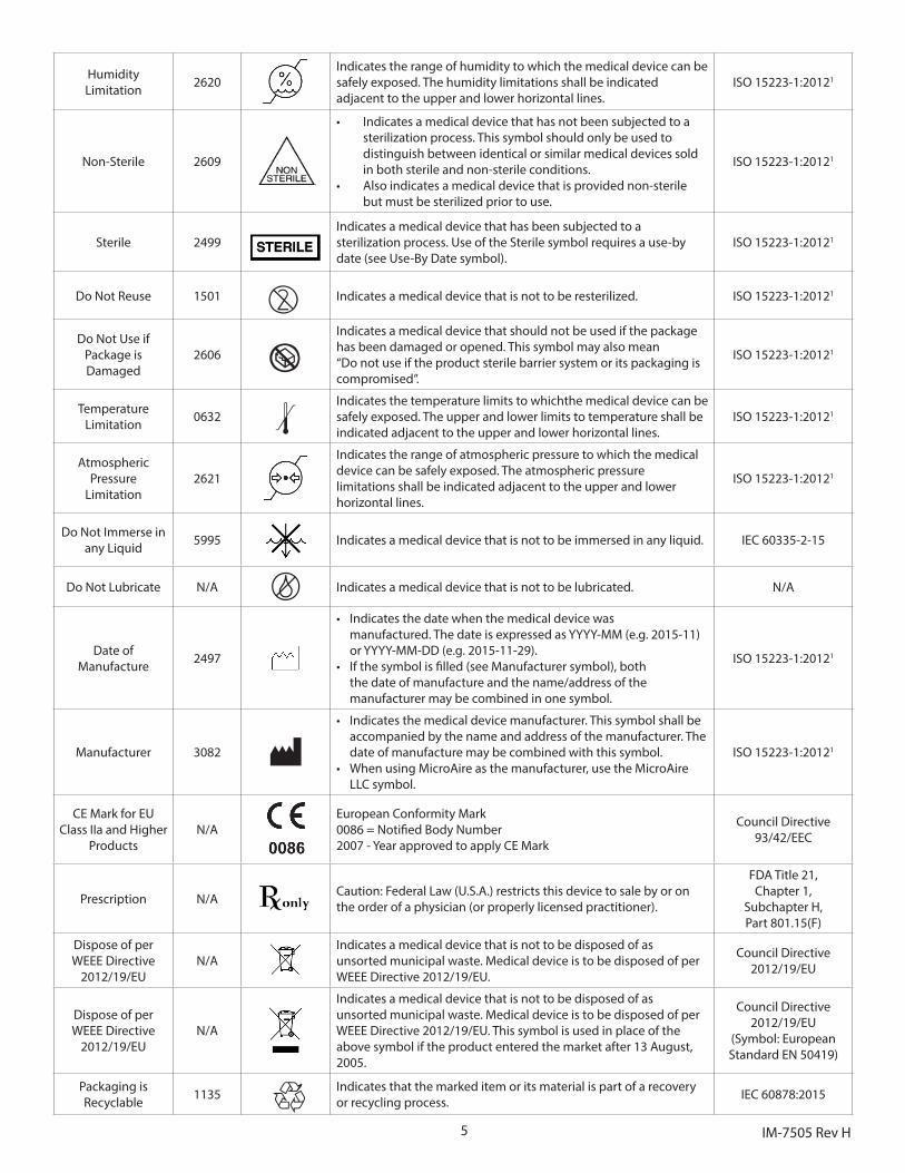
Humidity Limitation 2620
Indicates the range of humidity to which the medical device can be safely exposed. The humidity limitations shall be indicatedadjacent to the upper and lower horizontal lines.
ISO 15223-1:20121
Non-Sterile 2609
• Indicates a medical device that has not been subjected to a sterilization process. This symbol should only be used to distinguish between identical or similar medical devices sold in both sterile and non-sterile conditions.
• Also indicates a medical device that is provided non-sterile but must be sterilized prior to use.
ISO 15223-1:20121
Sterile 2499Indicates a medical device that has been subjected to a sterilization process. Use of the Sterile symbol requires a use-by date (see Use-By Date symbol).
ISO 15223-1:20121
Do Not Reuse 1501 2 Indicates a medical device that is not to be resterilized. ISO 15223-1:20121
Do Not Use ifPackage isDamaged
2606 wIndicates a medical device that should not be used if the package has been damaged or opened. This symbol may also mean “Do not use if the product sterile barrier system or its packaging is compromised”.
ISO 15223-1:20121
TemperatureLimitation 0632 >
Indicates the temperature limits to whichthe medical device can be safely exposed. The upper and lower limits to temperature shall be indicated adjacent to the upper and lower horizontal lines.
ISO 15223-1:20121
Atmospheric Pressure
Limitation2621
Indicates the range of atmospheric pressure to which the medical device can be safely exposed. The atmospheric pressurelimitations shall be indicated adjacent to the upper and lower horizontal lines.
ISO 15223-1:20121
Do Not Immerse in any Liquid 5995 Indicates a medical device that is not to be immersed in any liquid. IEC 60335-2-15
Do Not Lubricate N/A Indicates a medical device that is not to be lubricated. N/A
Date of Manufacture 2497
• Indicates the date when the medical device was manufactured. The date is expressed as YYYY-MM (e.g. 2015-11) or YYYY-MM-DD (e.g. 2015-11-29).
• If the symbol is filled (see Manufacturer symbol), both the date of manufacture and the name/address of the manufacturer may be combined in one symbol.
ISO 15223-1:20121
Manufacturer 3082
• Indicates the medical device manufacturer. This symbol shall be accompanied by the name and address of the manufacturer. The date of manufacture may be combined with this symbol.
• When using MicroAire as the manufacturer, use the MicroAire LLC symbol.
ISO 15223-1:20121
CE Mark for EU Class IIa and Higher
ProductsN/A
European Conformity Mark 0086 = Notified Body Number 2007 - Year approved to apply CE Mark
Council Directive93/42/EEC
Prescription N/A Caution: Federal Law (U.S.A.) restricts this device to sale by or on the order of a physician (or properly licensed practitioner).
FDA Title 21, Chapter 1,
Subchapter H, Part 801.15(F)
Dispose of per WEEE Directive
2012/19/EUN/A
Indicates a medical device that is not to be disposed of as unsorted municipal waste. Medical device is to be disposed of per WEEE Directive 2012/19/EU.
Council Directive 2012/19/EU
Dispose of per WEEE Directive
2012/19/EUN/A
Indicates a medical device that is not to be disposed of as unsorted municipal waste. Medical device is to be disposed of per WEEE Directive 2012/19/EU. This symbol is used in place of the above symbol if the product entered the market after 13 August, 2005.
Council Directive 2012/19/EU
(Symbol: European Standard EN 50419)
Packaging is Recyclable 1135 Indicates that the marked item or its material is part of a recovery
or recycling process. IEC 60878:2015
6IM-7505 Rev H
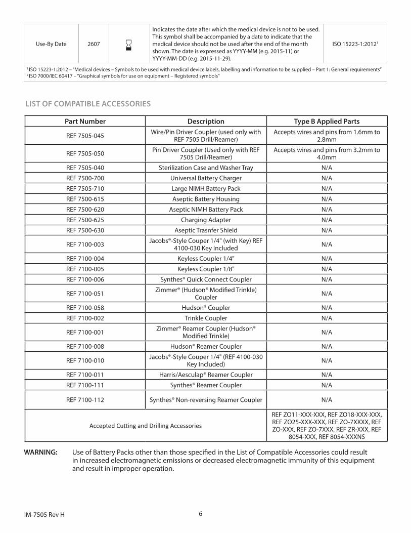
LIST OF COMPATIBLE ACCESSORIES
Part Number Description Type B Applied Parts
REF 7505-045 Wire/Pin Driver Coupler (used only with REF 7505 Drill/Reamer)
Accepts wires and pins from 1.6mm to 2.8mm
REF 7505-050 Pin Driver Coupler (Used only with REF 7505 Drill/Reamer)
Accepts wires and pins from 3.2mm to 4.0mm
REF 7505-040 Sterilization Case and Washer Tray N/A
REF 7500-700 Universal Battery Charger N/A
REF 7505-710 Large NIMH Battery Pack N/A
REF 7500-615 Aseptic Battery Housing N/A
REF 7500-620 Aseptic NIMH Battery Pack N/A
REF 7500-625 Charging Adapter N/A
REF 7500-630 Aseptic Trasnfer Shield N/A
REF 7100-003 Jacobs®-Style Couper 1/4" (with Key) REF 4100-030 Key Included N/A
REF 7100-004 Keyless Coupler 1/4" N/A
REF 7100-005 Keyless Coupler 1/8" N/A
REF 7100-006 Synthes® Quick Connect Coupler N/A
REF 7100-051 Zimmer® (Hudson® Modified Trinkle) Coupler N/A
REF 7100-058 Hudson® Coupler N/A
REF 7100-002 Trinkle Coupler N/A
REF 7100-001 Zimmer® Reamer Coupler (Hudson® Modified Trinkle) N/A
REF 7100-008 Hudson® Reamer Coupler N/A
REF 7100-010 Jacobs®-Style Couper 1/4" (REF 4100-030 Key Included) N/A
REF 7100-011 Harris/Aesculap® Reamer Coupler N/A
REF 7100-111 Synthes® Reamer Coupler N/A
REF 7100-112 Synthes® Non-reversing Reamer Coupler N/A
Accepted Cutting and Drilling Accessories
REF ZO11-XXX-XXX, REF ZO18-XXX-XXX, REF ZO25-XXX-XXX, REF ZO-7XXXX, REF ZO-XXX, REF ZO-7XXX, REF ZR-XXX, REF
8054-XXX, REF 8054-XXXNS
WARNING: Use of Battery Packs other than those specified in the List of Compatible Accessories could result in increased electromagnetic emissions or decreased electromagnetic immunity of this equipment and result in improper operation.
Use-By Date 2607 tIndicates the date after which the medical device is not to be used. This symbol shall be accompanied by a date to indicate that the medical device should not be used after the end of the month shown. The date is expressed as YYYY-MM (e.g. 2015-11) or YYYY-MM-DD (e.g. 2015-11-29).
ISO 15223-1:20121
1 ISO 15223-1:2012 – “Medical devices – Symbols to be used with medical device labels, labelling and information to be supplied – Part 1: General requirements” 2 ISO 7000/IEC 60417 – “Graphical symbols for use on equipment – Registered symbols”
7 IM-7505 Rev H
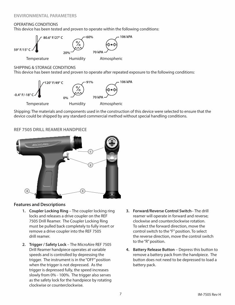
ENVIRONMENTAL PARAMETERS
OPERATING CONDITIONS This device has been tested and proven to operate within the following conditions:
Temperature Humidity Atmospheric
59° F/15° C
80.6° F/27° C
> 20%
60%
70 kPA
106 kPA
SHIPPING & STORAGE CONDITIONSThis device has been tested and proven to operate after repeated exposure to the following conditions:
Temperature Humidity Atmospheric
-0.4° F/-18° C
120° F/49° C
> 0%
91%
70 kPA
106 kPA
Shipping: The materials and components used in the construction of this device were selected to ensure that the device could be shipped by any standard commercial method without special handling conditions.
REF 7505 DRILL REAMER HANDPIECE
1
2
34
Features and Descriptions1. Coupler Locking Ring – The coupler locking ring
locks and releases a drive coupler on the REF 7505 Drill Reamer. The Coupler Locking Ring must be pulled back completely to fully insert or remove a drive coupler into the REF 7505 drill reamer.
2. Trigger / Safety Lock – The MicroAire REF 7505 Drill Reamer handpiece operates at variable speeds and is controlled by depressing the trigger. The instrument is in the “OFF” position when the trigger is not depressed. As the trigger is depressed fully, the speed increases slowly from 0% - 100%. The trigger also serves as the safety lock for the handpiece by rotating clockwise or counterclockwise.
3. Forward/Reverse Control Switch– The drill reamer will operate in forward and reverse; clockwise and counterclockwise rotation. To select the forward direction, move the control switch to the “F” position. To select the reverse direction, move the control switch to the “R” position.
4. Battery Release Button – Depress this button to remove a battery pack from the handpiece. The button does not need to be depressed to load a battery pack.
8IM-7505 Rev H
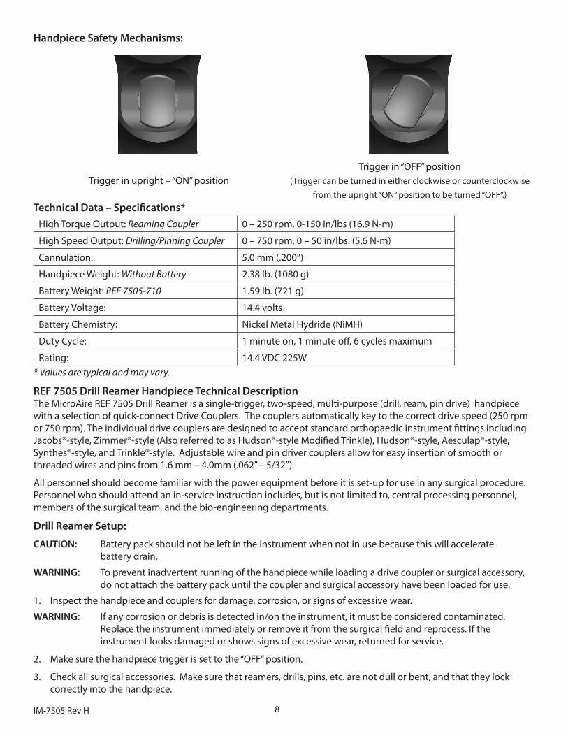
Handpiece Safety Mechanisms:
Trigger in upright – “ON” positionTrigger in “OFF” position
(Trigger can be turned in either clockwise or counterclockwise from the upright “ON” position to be turned “OFF”.)
Technical Data – Specifications*High Torque Output: Reaming Coupler 0 – 250 rpm, 0-150 in/lbs (16.9 N-m)
High Speed Output: Drilling/Pinning Coupler 0 – 750 rpm, 0 – 50 in/lbs. (5.6 N-m)
Cannulation: 5.0 mm (.200”)
Handpiece Weight: Without Battery 2.38 lb. (1080 g)
Battery Weight: REF 7505-710 1.59 lb. (721 g)
Battery Voltage: 14.4 volts
Battery Chemistry: Nickel Metal Hydride (NiMH)
Duty Cycle: 1 minute on, 1 minute off, 6 cycles maximum
Rating: 14.4 VDC 225W* Values are typical and may vary.
REF 7505 Drill Reamer Handpiece Technical DescriptionThe MicroAire REF 7505 Drill Reamer is a single-trigger, two-speed, multi-purpose (drill, ream, pin drive) handpiece with a selection of quick-connect Drive Couplers. The couplers automatically key to the correct drive speed (250 rpm or 750 rpm). The individual drive couplers are designed to accept standard orthopaedic instrument fittings including Jacobs®-style, Zimmer®-style (Also referred to as Hudson®-style Modified Trinkle), Hudson®-style, Aesculap®-style, Synthes®-style, and Trinkle®-style. Adjustable wire and pin driver couplers allow for easy insertion of smooth or threaded wires and pins from 1.6 mm – 4.0mm (.062” – 5/32”).
All personnel should become familiar with the power equipment before it is set-up for use in any surgical procedure. Personnel who should attend an in-service instruction includes, but is not limited to, central processing personnel, members of the surgical team, and the bio-engineering departments.
Drill Reamer Setup:
CAUTION: Battery pack should not be left in the instrument when not in use because this will accelerate battery drain.
WARNING: To prevent inadvertent running of the handpiece while loading a drive coupler or surgical accessory, do not attach the battery pack until the coupler and surgical accessory have been loaded for use.
1. Inspect the handpiece and couplers for damage, corrosion, or signs of excessive wear.
WARNING: If any corrosion or debris is detected in/on the instrument, it must be considered contaminated. Replace the instrument immediately or remove it from the surgical field and reprocess. If the instrument looks damaged or shows signs of excessive wear, returned for service.
2. Make sure the handpiece trigger is set to the “OFF” position.
3. Check all surgical accessories. Make sure that reamers, drills, pins, etc. are not dull or bent, and that they lock correctly into the handpiece.
9 IM-7505 Rev H
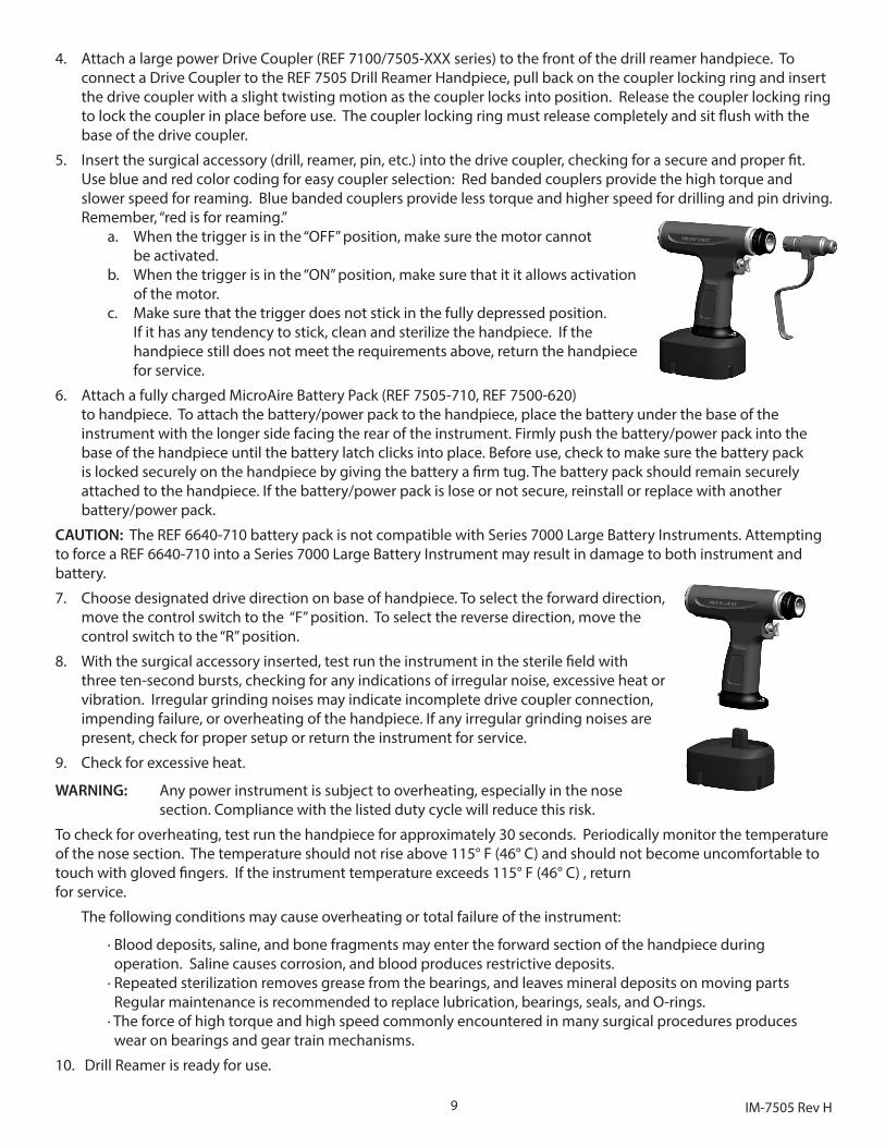
4. Attach a large power Drive Coupler (REF 7100/7505-XXX series) to the front of the drill reamer handpiece. To connect a Drive Coupler to the REF 7505 Drill Reamer Handpiece, pull back on the coupler locking ring and insert the drive coupler with a slight twisting motion as the coupler locks into position. Release the coupler locking ring to lock the coupler in place before use. The coupler locking ring must release completely and sit flush with the base of the drive coupler.
5. Insert the surgical accessory (drill, reamer, pin, etc.) into the drive coupler, checking for a secure and proper fit. Use blue and red color coding for easy coupler selection: Red banded couplers provide the high torque and slower speed for reaming. Blue banded couplers provide less torque and higher speed for drilling and pin driving. Remember, “red is for reaming.”
a. When the trigger is in the “OFF” position, make sure the motor cannot be activated.
b. When the trigger is in the “ON” position, make sure that it it allows activation of the motor.
c. Make sure that the trigger does not stick in the fully depressed position. If it has any tendency to stick, clean and sterilize the handpiece. If the handpiece still does not meet the requirements above, return the handpiece for service.
6. Attach a fully charged MicroAire Battery Pack (REF 7505-710, REF 7500-620) to handpiece. To attach the battery/power pack to the handpiece, place the battery under the base of the instrument with the longer side facing the rear of the instrument. Firmly push the battery/power pack into the base of the handpiece until the battery latch clicks into place. Before use, check to make sure the battery pack is locked securely on the handpiece by giving the battery a firm tug. The battery pack should remain securely attached to the handpiece. If the battery/power pack is lose or not secure, reinstall or replace with another battery/power pack.
CAUTION: The REF 6640-710 battery pack is not compatible with Series 7000 Large Battery Instruments. Attempting to force a REF 6640-710 into a Series 7000 Large Battery Instrument may result in damage to both instrument and battery.
7. Choose designated drive direction on base of handpiece. To select the forward direction, move the control switch to the “F” position. To select the reverse direction, move the control switch to the “R” position.
8. With the surgical accessory inserted, test run the instrument in the sterile field with three ten-second bursts, checking for any indications of irregular noise, excessive heat or vibration. Irregular grinding noises may indicate incomplete drive coupler connection, impending failure, or overheating of the handpiece. If any irregular grinding noises are present, check for proper setup or return the instrument for service.
9. Check for excessive heat.
WARNING: Any power instrument is subject to overheating, especially in the nose section. Compliance with the listed duty cycle will reduce this risk.
To check for overheating, test run the handpiece for approximately 30 seconds. Periodically monitor the temperature of the nose section. The temperature should not rise above 115° F (46° C) and should not become uncomfortable to touch with gloved fingers. If the instrument temperature exceeds 115° F (46° C) , return for service.
The following conditions may cause overheating or total failure of the instrument:
· Blood deposits, saline, and bone fragments may enter the forward section of the handpiece during operation. Saline causes corrosion, and blood produces restrictive deposits. · Repeated sterilization removes grease from the bearings, and leaves mineral deposits on moving parts Regular maintenance is recommended to replace lubrication, bearings, seals, and O-rings. · The force of high torque and high speed commonly encountered in many surgical procedures produces wear on bearings and gear train mechanisms.
10. Drill Reamer is ready for use.
10IM-7505 Rev H
REF 7506 OSCILLATING SAW HANDPIECE
2
3
45
1
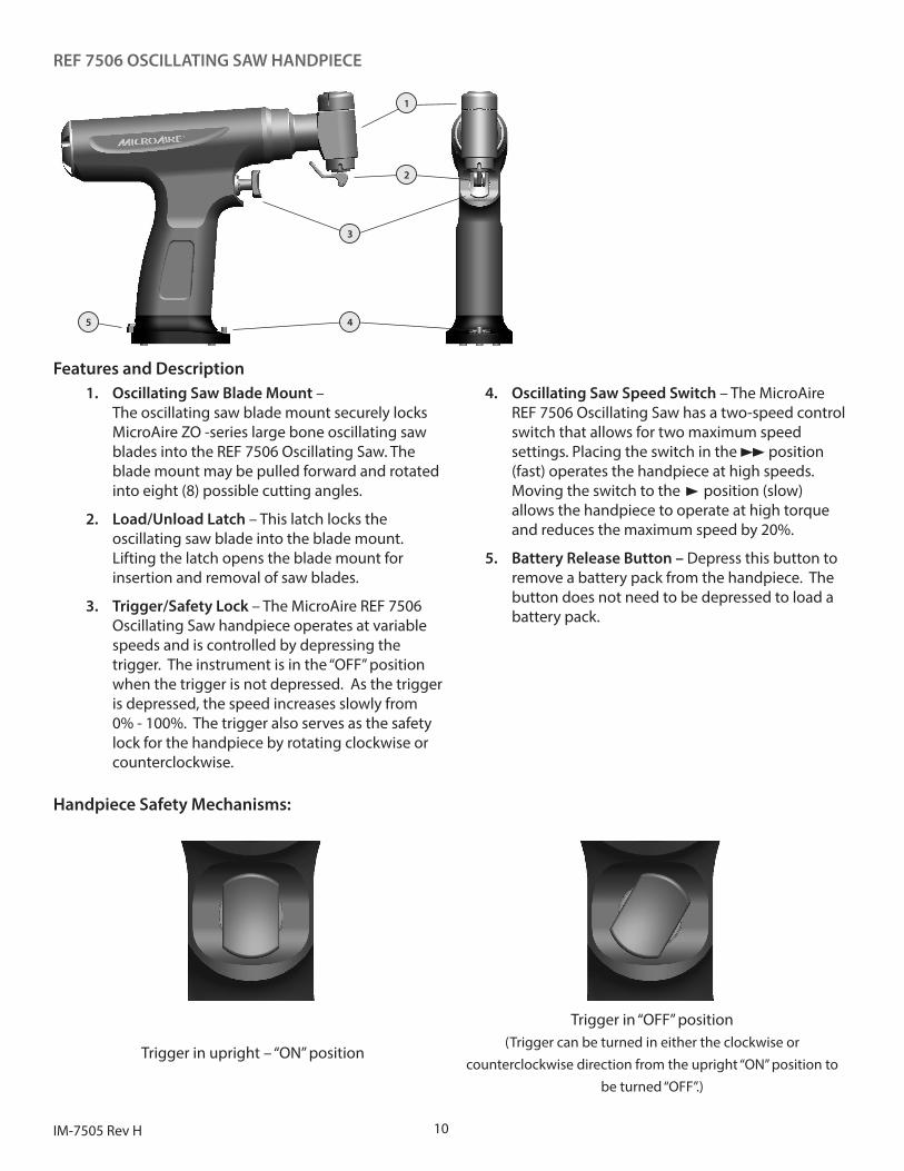
Features and Description1. Oscillating Saw Blade Mount –
The oscillating saw blade mount securely locks MicroAire ZO -series large bone oscillating saw blades into the REF 7506 Oscillating Saw. The blade mount may be pulled forward and rotated into eight (8) possible cutting angles.
2. Load/Unload Latch – This latch locks the oscillating saw blade into the blade mount. Lifting the latch opens the blade mount for insertion and removal of saw blades.
3. Trigger/Safety Lock – The MicroAire REF 7506 Oscillating Saw handpiece operates at variable speeds and is controlled by depressing the trigger. The instrument is in the “OFF” position when the trigger is not depressed. As the trigger is depressed, the speed increases slowly from 0% - 100%. The trigger also serves as the safety lock for the handpiece by rotating clockwise or counterclockwise.
4. Oscillating Saw Speed Switch – The MicroAire REF 7506 Oscillating Saw has a two-speed control switch that allows for two maximum speed settings. Placing the switch in the position (fast) operates the handpiece at high speeds. Moving the switch to the p position (slow) allows the handpiece to operate at high torque and reduces the maximum speed by 20%.
5. Battery Release Button – Depress this button to remove a battery pack from the handpiece. The button does not need to be depressed to load a battery pack.
Handpiece Safety Mechanisms:
Trigger in upright – “ON” position
Trigger in “OFF” position(Trigger can be turned in either the clockwise or
counterclockwise direction from the upright “ON” position to be turned “OFF”.)
11 IM-7505 Rev H
Technical Data – Specifications*Oscillating Saw Speed: 0 – 15,000 cpm,
Setting: 0 – 15,000 cpm maximum
p Setting: 0 – 12,000 cpm maximum
Blade Cutting Arc: 4°
Handpiece Weight: Without Battery 2.63 lb. (1196 g)
Battery Weight: REF 7505-710 1.59 lb. (721 g)
Battery Voltage: 14.4 volts
Battery Chemistry: Nickel Metal Hydride (NiMH)
Duty Cycle: 1 minute on, 1 minute off, 6 cycles maximumRating: 14.4 VDC 225 W
* Values are typical and may vary
REF 7506 Oscillating Saw Handpiece Technical DescriptionThe MicroAire REF 7506 Oscillating Saw is a single-trigger, variable speed, multi-purpose handpiece designed for total joint arthroplasty. The saw’s heavy-duty high-speed oscillating mechanism is designed to drive the extra-long and wide saw blades required for total knee osteotomies. The oscillating saw may also be used in total hip arthroplasty, trauma, and revision sternotomies.
All personnel should become familiar with the power equipment before it is set-up for use in any surgical procedure. Personnel who should attend an in-service instruction includes, but is not limited to, central processing personnel, members of the surgical team, and the bio-engineering departments.
Oscillating Saw Setup:CAUTION: Battery pack should not be left in the instrument when not in use because this will accelerate battery drain.
WARNING: To prevent inadvertent running of the handpiece while loading a saw blade, do not attach the battery pack until the saw blade has been securely locked into place and is ready for use.
1. Inspect the handpiece for damage, corrosion, or signs of excessive wear.
WARNING: If any corrosion or debris is detected in/on the instrument, it must be considered contaminated. Replace the instrument immediately or remove it from the surgical field and reprocess. If the instrument looks damaged or shows signs of excessive wear, return for service.
2. Make sure the handpiece trigger is set to the “OFF” position.
3. Check all surgical accessories. Make sure that saw blades are not dull or bent, and that they lock correctly into the handpiece.
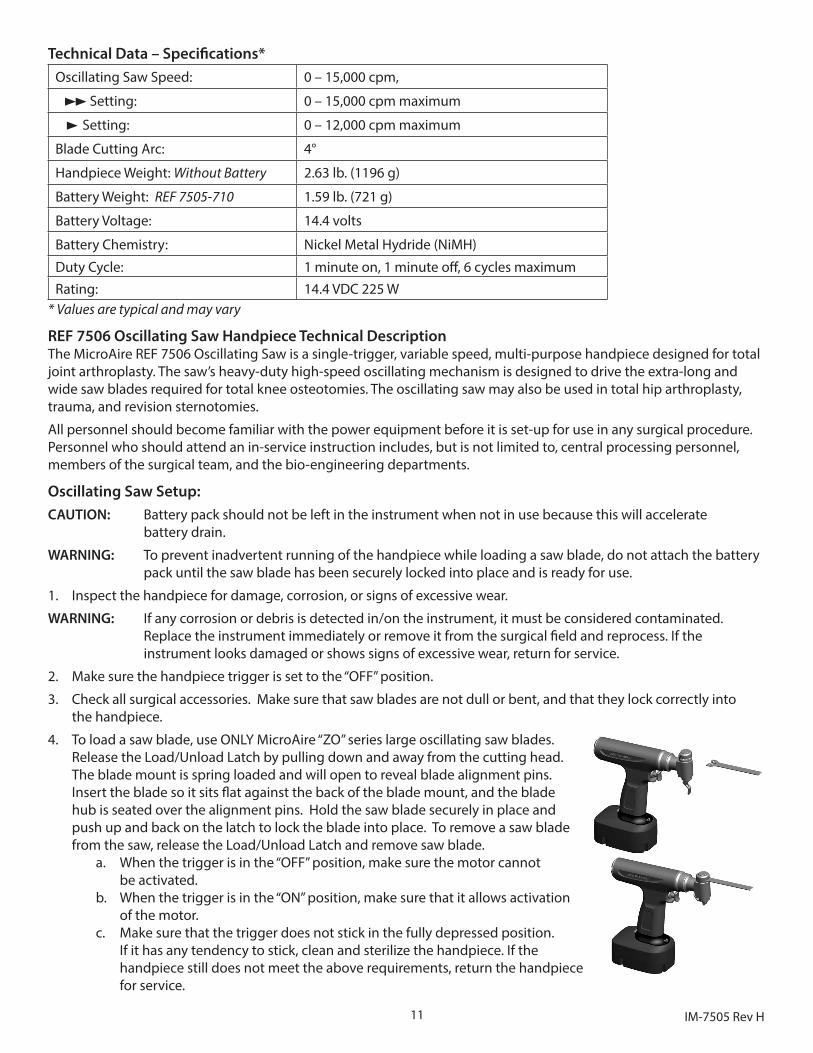
4. To load a saw blade, use ONLY MicroAire “ZO” series large oscillating saw blades. Release the Load/Unload Latch by pulling down and away from the cutting head. The blade mount is spring loaded and will open to reveal blade alignment pins. Insert the blade so it sits flat against the back of the blade mount, and the blade hub is seated over the alignment pins. Hold the saw blade securely in place and push up and back on the latch to lock the blade into place. To remove a saw blade from the saw, release the Load/Unload Latch and remove saw blade.
a. When the trigger is in the “OFF” position, make sure the motor cannot be activated.
b. When the trigger is in the “ON” position, make sure that it allows activation of the motor.
c. Make sure that the trigger does not stick in the fully depressed position. If it has any tendency to stick, clean and sterilize the handpiece. If the handpiece still does not meet the above requirements, return the handpiece for service.
12IM-7505 Rev H
5. Attach a fully charged MicroAire Battery Pack (REF 7505-710, REF 7500-620) to handpiece. To attach the battery/power pack to the handpiece, place the battery under the base of the instrument with the longer side facing the rear of the instrument. Firmly push the battery/power pack into the base of the handpiece until the battery latch clicks into place. Before use, check to make sure the battery pack is locked securely on the handpiece by giving the battery a firm tug. The battery pack should remain securely attached to the handpiece. If the battery/power pack is lose or not secure, reinstall or replace with another battery/power pack.
CAUTION: The REF 6640-710 battery pack is not compatible with Series 7000 Large Battery Instruments. Attempting to force a REF 6640-710 into a Series 7000 Large Battery Instrument may result in damage to both instrument and battery.
6. Choose designated speed control option on base of handpiece. To select the standard (high-speed) setting, move the control switch to the position. To select the slow (reduced speed) p setting, move the control switch to the p position.
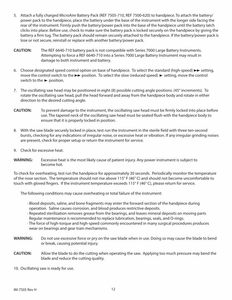
7. The oscillating saw head may be positioned in eight (8) possible cutting angle positions. (45° increments). To rotate the oscillating saw head, pull the head forward and away from the handpiece body and rotate in either direction to the desired cutting angle.
CAUTION: To prevent damage to the instrument, the oscillating saw head must be firmly locked into place before use. The tapered neck of the oscillating saw head must be seated flush with the handpiece body to ensure that it is properly locked in position.
8. With the saw blade securely locked in place, test run the instrument in the sterile field with three ten-second bursts, checking for any indications of irregular noise, or excessive heat or vibration. If any irregular grinding noises are present, check for proper setup or return the instrument for service.
9. Check for excessive heat.
WARNING: Excessive heat is the most likely cause of patient injury. Any power instrument is subject to become hot.
To check for overheating, test run the handpiece for approximately 30 seconds. Periodically monitor the temperature of the nose section. The temperature should not rise above 115° F (46° C) and should not become uncomfortable to touch with gloved fingers. If the instrument temperature exceeds 115° F (46° C), please return for service.
The following conditions may cause overheating or total failure of the instrument:
· Blood deposits, saline, and bone fragments may enter the forward section of the handpiece during operation. Saline causes corrosion, and blood produces restrictive deposits. · Repeated sterilization removes grease from the bearings, and leaves mineral deposits on moving parts Regular maintenance is recommended to replace lubrication, bearings, seals, and O-rings. · The force of high-torque and high-speed commonly encountered in many surgical procedures produces wear on bearings and gear train mechanisms.
WARNING: Do not use excessive force or pry on the saw blade when in use. Doing so may cause the blade to bend or break, causing potential injury.
CAUTION: Allow the blade to do the cutting when operating the saw. Applying too much pressure may bend the blade and reduce the cutting quality.
10. Oscillating saw is ready for use.
13 IM-7505 Rev H
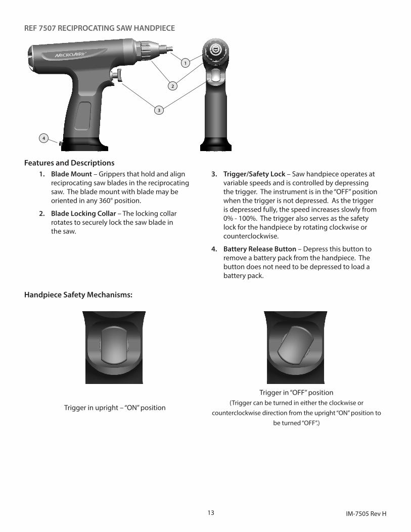
REF 7507 RECIPROCATING SAW HANDPIECE
1
2
3
4
Features and Descriptions1. Blade Mount – Grippers that hold and align
reciprocating saw blades in the reciprocating saw. The blade mount with blade may be oriented in any 360° position.
2. Blade Locking Collar – The locking collar rotates to securely lock the saw blade in the saw.
3. Trigger/Safety Lock – Saw handpiece operates at variable speeds and is controlled by depressing the trigger. The instrument is in the “OFF” position when the trigger is not depressed. As the trigger is depressed fully, the speed increases slowly from 0% - 100%. The trigger also serves as the safety lock for the handpiece by rotating clockwise or counterclockwise.
4. Battery Release Button – Depress this button to remove a battery pack from the handpiece. The button does not need to be depressed to load a battery pack.
Handpiece Safety Mechanisms:
Trigger in upright – “ON” position
Trigger in “OFF” position(Trigger can be turned in either the clockwise or
counterclockwise direction from the upright “ON” position to be turned “OFF”.)
14IM-7505 Rev H
Technical Data – Specifications*Reciprocating Saw Speed: 0 – 15,000 cpm
Blade Cutting Stroke: 3.2 mm (.125”)
Handpiece Weight: Without Battery 2.59 lbs. (1175 g)
Battery Weight: REF 7505-710 1.59 lbs. (721 g)
Battery Voltage: 14.4 volts
Battery Chemistry: Nickel Metal Hydride (NiMH)Duty Cycle: 1 minute on, 1 minute off, 6 cycles maximumRating: 14.4 VDC 225W
* Values are typical and may vary.
REF 7507 Reciprocating Saw Handpiece Technical DescriptionThe MicroAire REF 7507 Reciprocating Saw handpiece is a single-trigger, variable speed, multi-purpose handpiece designed for linear bone cutting in total joint arthroplasy and other large-bone orthopaedic procedures.
All personnel should become familiar with the power equipment before it is setup for use in any surgical procedure. Personnel who should attend an in-service instruction includes, but is not limited to, central processing personnel, members of the surgical team, and the bio-engineering departments.
Reciprocating Saw Setup:
CAUTION: Battery pack should not be left in the instrument when not in use because this will accelerate battery drain.
WARNING: To prevent inadvertent running of the handpiece while loading a drive coupler or surgical accessory, do not attach the battery pack until the coupler and surgical accessory have been loaded for use.
1. Inspect the handpiece for damage, corrosion, or signs of excessive wear.
WARNING: If any corrosion or debris is detected in/on the instrument, it must be considered contaminated. Replace the instrument immediately or remove it from the surgical field and reprocess. If the instrument looks damaged or shows signs of excessive wear, return for service.
2. Make sure the handpiece trigger is set to the “OFF” position.
3. Check all surgical accessories. Make sure that saw blades are not dull or bent, and that they lock correctly into the handpiece.
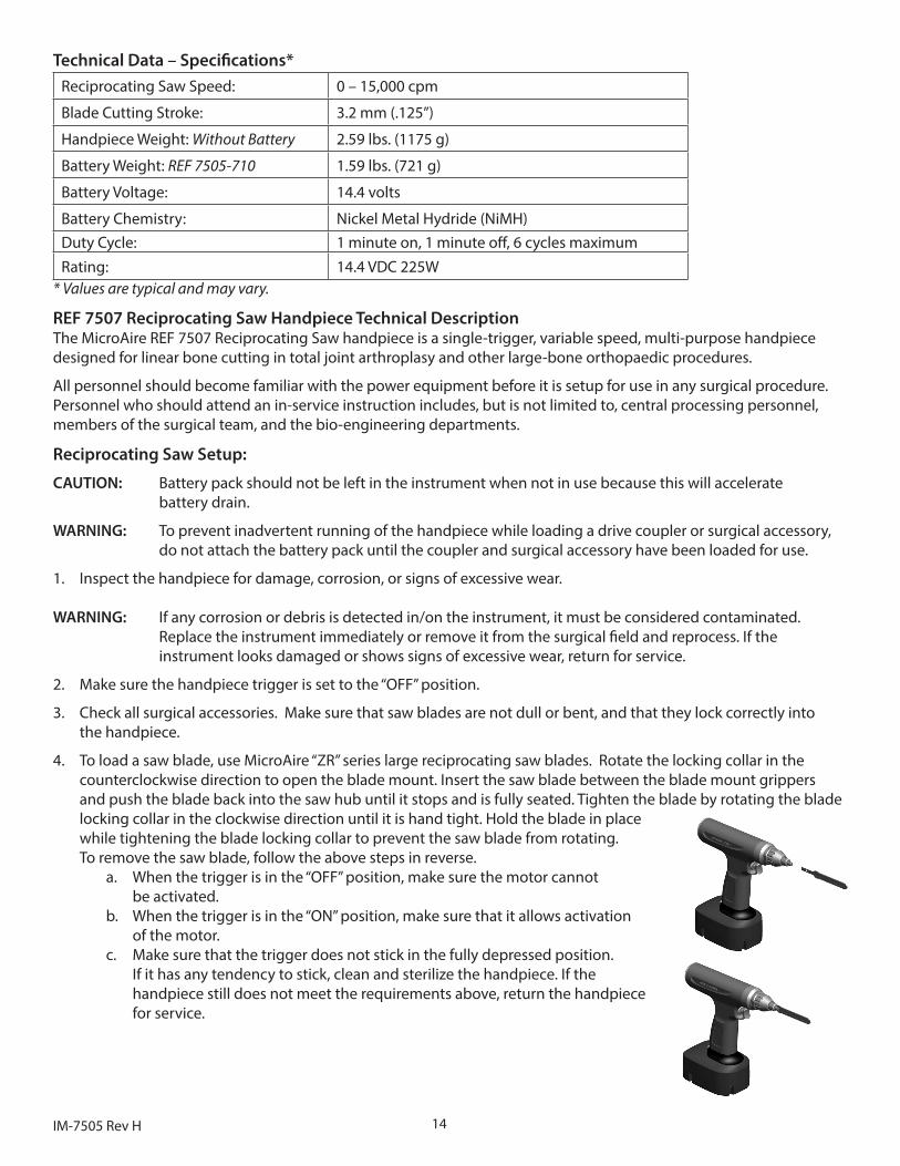
4. To load a saw blade, use MicroAire “ZR” series large reciprocating saw blades. Rotate the locking collar in the counterclockwise direction to open the blade mount. Insert the saw blade between the blade mount grippers and push the blade back into the saw hub until it stops and is fully seated. Tighten the blade by rotating the blade locking collar in the clockwise direction until it is hand tight. Hold the blade in place while tightening the blade locking collar to prevent the saw blade from rotating. To remove the saw blade, follow the above steps in reverse.
a. When the trigger is in the “OFF” position, make sure the motor cannot be activated.
b. When the trigger is in the “ON” position, make sure that it allows activation of the motor.
c. Make sure that the trigger does not stick in the fully depressed position. If it has any tendency to stick, clean and sterilize the handpiece. If the handpiece still does not meet the requirements above, return the handpiece for service.
15 IM-7505 Rev H
5. Attach a fully charged MicroAire Battery Pack (REF 7505-710, REF 7500-620) to handpiece. To attach the battery/power pack to the handpiece, place the battery under the base of the instrument with the longer side facing the rear of the instrument. Firmly push the battery/power pack into the base of the handpiece until the battery latch clicks into place. Before use, check to make sure the battery pack is locked securely on the handpiece by giving the battery a firm tug. The battery pack should remain securely attached to the handpiece. If the battery/power pack is lose or not secure, reinstall or replace with another battery/power pack.
CAUTION: The REF 6640-710 battery pack is not compatible with Series 7000 Large Battery Instruments. Attempting to force a REF 6640-710 into a Series 7000 Large Battery Instrument may result in damage to both instrument and battery.
6. With the saw blade securely locked in place, test run the instrument in the sterile field with three ten-second bursts, checking for any indications of irregular noise, or excessive heat or vibration. Irregular grinding noises may indicate impending failure or over heating of the handpiece. If any irregular grinding noises are present, check for proper setup or return the instrument for service.
7. Check for excessive heat.
WARNING: Excessive heat is the most likely cause of patient injury. Any power instrument is subject to become hot.
To check for overheating, test run the handpiece for approximately 30 seconds. Periodically monitor the temperature of the nose section. The temperature should not rise above 115° F (46° C) and should not become uncomfortable to touch with gloved fingers. If the instrument temperature exceeds 115° F (46° C), please return for service.
The following conditions may cause overheating or total failure of the instrument:
· Blood deposits, saline, and bone fragments may enter the forward section of the handpiece during operation. Saline causes corrosion, and blood produces restrictive deposits. · Repeated sterilization removes grease from the bearings, and leaves mineral deposits on moving parts. Regular maintenance is recommended to replace lubrication, bearings, seals, and o-rings. · The force of high torque and high speed commonly encountered in many surgical procedures produces wear on bearings and gear train mechanisms.
WARNING: Large reciprocating saw blades are longer in length and can whip when the handpiece is operated below the maximum speed. Personnel should be alert. Blade whip can increase the chance of blade fracture and user/patient injury.
WARNING: Do not use excessive force or pry on the saw blade when in use. Doing so may cause the blade to bend or break, causing potential injury.
CAUTION: Allow the blade to do the cutting when operating the saw. Applying too much pressure may bend the blade and reduce the cutting quality.
8. Reciprocating saw is ready for use.
SERIES 7000 BATTERY INSTRUCTIONS
Battery ChargingSee separate operating instructions provided with the MicroAire UL Classified Battery Charger (REF 7500-700).
Battery InstallationThe Series 7000 Battery Large Power System must have a fully charged MicroAire battery pack (REF 7505-710 or Aseptic Battery installed before each use). To attach the battery to the handpiece, place the battery under the base of the instrument with the longer side facing the rear of the instrument. Firmly push the battery into the base of the handpiece until the battery latch clicks into place. Before use, check to make sure the battery pack is locked securely on the handpiece by giving the battery a firm tug. The battery pack should remain securely attached to the handpiece. If the battery pack is lose or not secure, reinstall or replace with another battery.
16IM-7505 Rev H
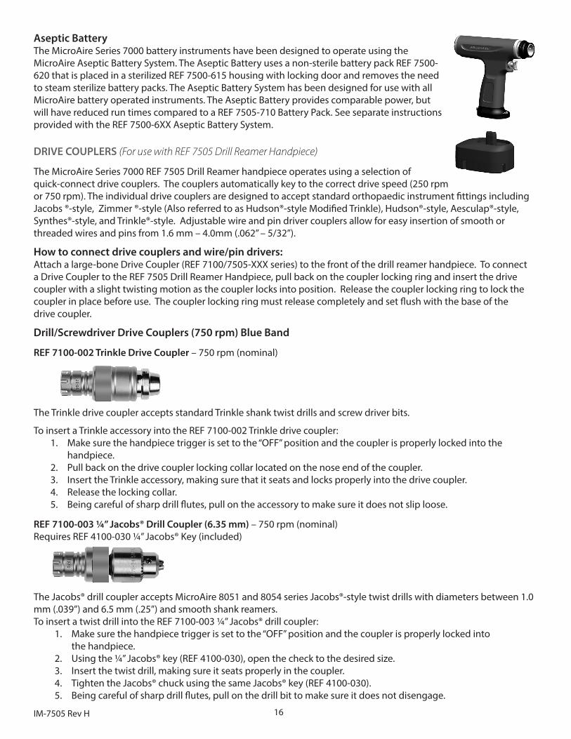
Aseptic Battery The MicroAire Series 7000 battery instruments have been designed to operate using the MicroAire Aseptic Battery System. The Aseptic Battery uses a non-sterile battery pack REF 7500-620 that is placed in a sterilized REF 7500-615 housing with locking door and removes the need to steam sterilize battery packs. The Aseptic Battery System has been designed for use with all MicroAire battery operated instruments. The Aseptic Battery provides comparable power, but will have reduced run times compared to a REF 7505-710 Battery Pack. See separate instructions provided with the REF 7500-6XX Aseptic Battery System.
DRIVE COUPLERS (For use with REF 7505 Drill Reamer Handpiece)
The MicroAire Series 7000 REF 7505 Drill Reamer handpiece operates using a selection of quick-connect drive couplers. The couplers automatically key to the correct drive speed (250 rpm or 750 rpm). The individual drive couplers are designed to accept standard orthopaedic instrument fittings including Jacobs ®-style, Zimmer ®-style (Also referred to as Hudson®-style Modified Trinkle), Hudson®-style, Aesculap®-style, Synthes®-style, and Trinkle®-style. Adjustable wire and pin driver couplers allow for easy insertion of smooth or threaded wires and pins from 1.6 mm – 4.0mm (.062” – 5/32”).
How to connect drive couplers and wire/pin drivers:Attach a large-bone Drive Coupler (REF 7100/7505-XXX series) to the front of the drill reamer handpiece. To connect a Drive Coupler to the REF 7505 Drill Reamer Handpiece, pull back on the coupler locking ring and insert the drive coupler with a slight twisting motion as the coupler locks into position. Release the coupler locking ring to lock the coupler in place before use. The coupler locking ring must release completely and set flush with the base of the drive coupler.
Drill/Screwdriver Drive Couplers (750 rpm) Blue Band
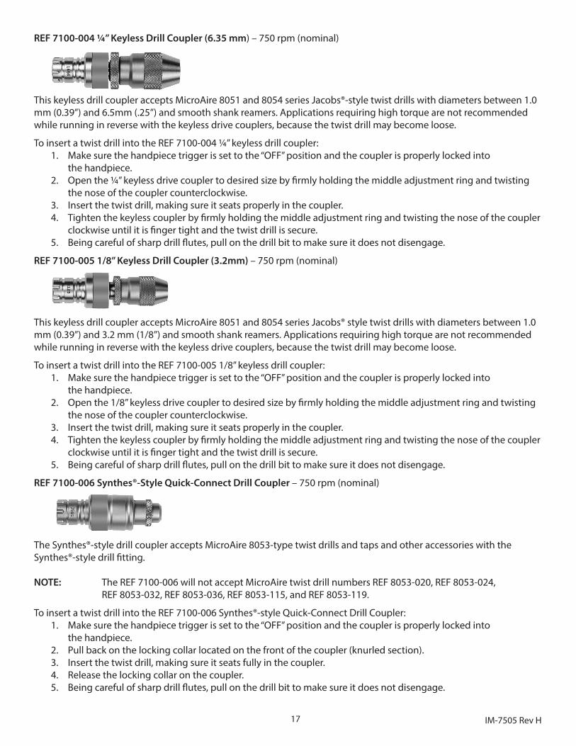
REF 7100-002 Trinkle Drive Coupler – 750 rpm (nominal)
The Trinkle drive coupler accepts standard Trinkle shank twist drills and screw driver bits.
To insert a Trinkle accessory into the REF 7100-002 Trinkle drive coupler:1. Make sure the handpiece trigger is set to the “OFF” position and the coupler is properly locked into the
handpiece.2. Pull back on the drive coupler locking collar located on the nose end of the coupler.3. Insert the Trinkle accessory, making sure that it seats and locks properly into the drive coupler.4. Release the locking collar.5. Being careful of sharp drill flutes, pull on the accessory to make sure it does not slip loose.
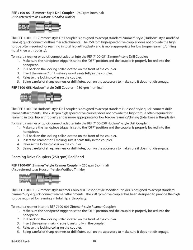
REF 7100-003 ¼” Jacobs® Drill Coupler (6.35 mm) – 750 rpm (nominal) Requires REF 4100-030 ¼” Jacobs® Key (included)
The Jacobs® drill coupler accepts MicroAire 8051 and 8054 series Jacobs®-style twist drills with diameters between 1.0 mm (.039”) and 6.5 mm (.25”) and smooth shank reamers.To insert a twist drill into the REF 7100-003 ¼” Jacobs® drill coupler:
1. Make sure the handpiece trigger is set to the “OFF” position and the coupler is properly locked into the handpiece.
2. Using the ¼” Jacobs® key (REF 4100-030), open the check to the desired size.3. Insert the twist drill, making sure it seats properly in the coupler.4. Tighten the Jacobs® chuck using the same Jacobs® key (REF 4100-030).5. Being careful of sharp drill flutes, pull on the drill bit to make sure it does not disengage.
17 IM-7505 Rev H
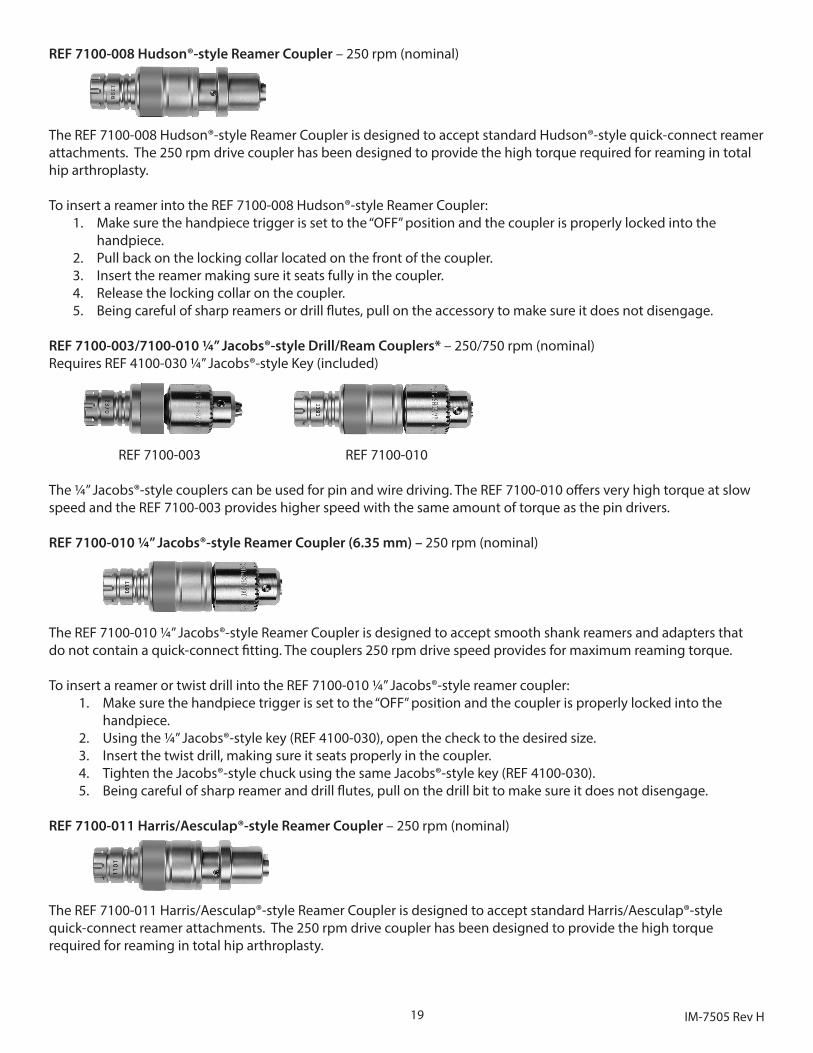
REF 7100-004 ¼” Keyless Drill Coupler (6.35 mm) – 750 rpm (nominal)
This keyless drill coupler accepts MicroAire 8051 and 8054 series Jacobs®-style twist drills with diameters between 1.0 mm (0.39”) and 6.5mm (.25”) and smooth shank reamers. Applications requiring high torque are not recommended while running in reverse with the keyless drive couplers, because the twist drill may become loose.
To insert a twist drill into the REF 7100-004 ¼” keyless drill coupler:1. Make sure the handpiece trigger is set to the “OFF” position and the coupler is properly locked into
the handpiece.2. Open the ¼” keyless drive coupler to desired size by firmly holding the middle adjustment ring and twisting
the nose of the coupler counterclockwise.3. Insert the twist drill, making sure it seats properly in the coupler.4. Tighten the keyless coupler by firmly holding the middle adjustment ring and twisting the nose of the coupler
clockwise until it is finger tight and the twist drill is secure.5. Being careful of sharp drill flutes, pull on the drill bit to make sure it does not disengage.
REF 7100-005 1/8” Keyless Drill Coupler (3.2mm) – 750 rpm (nominal)
This keyless drill coupler accepts MicroAire 8051 and 8054 series Jacobs® style twist drills with diameters between 1.0 mm (0.39”) and 3.2 mm (1/8”) and smooth shank reamers. Applications requiring high torque are not recommended while running in reverse with the keyless drive couplers, because the twist drill may become loose.
To insert a twist drill into the REF 7100-005 1/8” keyless drill coupler:1. Make sure the handpiece trigger is set to the “OFF” position and the coupler is properly locked into
the handpiece.2. Open the 1/8” keyless drive coupler to desired size by firmly holding the middle adjustment ring and twisting
the nose of the coupler counterclockwise.3. Insert the twist drill, making sure it seats properly in the coupler.4. Tighten the keyless coupler by firmly holding the middle adjustment ring and twisting the nose of the coupler
clockwise until it is finger tight and the twist drill is secure.5. Being careful of sharp drill flutes, pull on the drill bit to make sure it does not disengage.
REF 7100-006 Synthes®-Style Quick-Connect Drill Coupler – 750 rpm (nominal)
The Synthes®-style drill coupler accepts MicroAire 8053-type twist drills and taps and other accessories with the Synthes®-style drill fitting.
NOTE: The REF 7100-006 will not accept MicroAire twist drill numbers REF 8053-020, REF 8053-024, REF 8053-032, REF 8053-036, REF 8053-115, and REF 8053-119.
To insert a twist drill into the REF 7100-006 Synthes®-style Quick-Connect Drill Coupler:1. Make sure the handpiece trigger is set to the “OFF” position and the coupler is properly locked into
the handpiece.2. Pull back on the locking collar located on the front of the coupler (knurled section).3. Insert the twist drill, making sure it seats fully in the coupler.4. Release the locking collar on the coupler.5. Being careful of sharp drill flutes, pull on the drill bit to make sure it does not disengage.
18IM-7505 Rev H
REF 7100-051 Zimmer®-Style Drill Coupler – 750 rpm (nominal) (Also referred to as Hudson® Modified Trinkle)
The REF 7100-051 Zimmer®-style Drill coupler is designed to accept standard Zimmer®-style (Hudson®-style modified Trinkle) quick-connect drill/reamer attachments. The 750 rpm high-speed drive coupler does not provide the high torque often required for reaming in total hip arthroplasty and is more appropriate for low torque reaming/drilling (total knee arthroplasty).
To insert a reamer or quick-connect adapter into the REF 7100-051 Zimmer®-style Drill Coupler:1. Make sure the handpiece trigger is set to the “OFF” position and the coupler is properly locked into the
handpiece.2. Pull back on the locking collar located on the front of the coupler. 3. Insert the reamer/ drill making sure it seats fully in the coupler.4. Release the locking collar on the coupler.5. Being careful of sharp reamers or drill flutes, pull on the accessory to make sure it does not disengage.
REF 7100-058 Hudson®-style Drill Coupler – 750 rpm (nominal)
The REF 7100-058 Hudson®-style Drill coupler is designed to accept standard Hudson®-style quick-connect drill/reamer attachments. The 750 rpm high speed drive coupler does not provide the high torque often required for reaming in total hip arthroplasty and is more appropriate for low torque reaming/drilling (total knee arthroplasty).
To insert a reamer or quick-connect adapter into the REF 7100-058 Hudson® -style Drill Coupler:1. Make sure the handpiece trigger is set to the “OFF” position and the coupler is properly locked into the
handpiece.2. Pull back on the locking collar located on the front of the coupler. 3. Insert the reamer/ drill making sure it seats fully in the coupler.4. Release the locking collar on the coupler.5. Being careful of sharp reamers or drill flutes, pull on the accessory to make sure it does not disengage.
Reaming Drive Couplers (250 rpm) Red Band
REF 7100-001 Zimmer®-style Reamer Coupler – 250 rpm (nominal)(Also referred to as Hudson®-style Modified Trinkle)
The REF 7100-001 Zimmer®-style Reamer Coupler (Hudson®-style Modified Trinkle) is designed to accept standard Zimmer®-style quick-connect reamer attachments. The 250 rpm drive coupler has been designed to provide the high torque required for reaming in total hip arthroplasty.
To insert a reamer into the REF 7100-001 Zimmer®-style Reamer Coupler:1. Make sure the handpiece trigger is set to the “OFF” position and the coupler is properly locked into the
handpiece.2. Pull back on the locking collar located on the front of the coupler. 3. Insert the reamer making sure it seats fully in the coupler.4. Release the locking collar on the coupler.5. Being careful of sharp reamers or drill flutes, pull on the accessory to make sure it does not disengage.
19 IM-7505 Rev H
REF 7100-008 Hudson®-style Reamer Coupler – 250 rpm (nominal)
The REF 7100-008 Hudson®-style Reamer Coupler is designed to accept standard Hudson®-style quick-connect reamer attachments. The 250 rpm drive coupler has been designed to provide the high torque required for reaming in total hip arthroplasty.
To insert a reamer into the REF 7100-008 Hudson®-style Reamer Coupler:1. Make sure the handpiece trigger is set to the “OFF” position and the coupler is properly locked into the
handpiece.2. Pull back on the locking collar located on the front of the coupler. 3. Insert the reamer making sure it seats fully in the coupler.4. Release the locking collar on the coupler.5. Being careful of sharp reamers or drill flutes, pull on the accessory to make sure it does not disengage.
REF 7100-003/7100-010 ¼” Jacobs®-style Drill/Ream Couplers* – 250/750 rpm (nominal)Requires REF 4100-030 ¼” Jacobs®-style Key (included)
REF 7100-003 REF 7100-010
The ¼” Jacobs®-style couplers can be used for pin and wire driving. The REF 7100-010 offers very high torque at slow speed and the REF 7100-003 provides higher speed with the same amount of torque as the pin drivers.
REF 7100-010 ¼” Jacobs®-style Reamer Coupler (6.35 mm) – 250 rpm (nominal)
The REF 7100-010 ¼” Jacobs®-style Reamer Coupler is designed to accept smooth shank reamers and adapters that do not contain a quick-connect fitting. The couplers 250 rpm drive speed provides for maximum reaming torque.
To insert a reamer or twist drill into the REF 7100-010 ¼” Jacobs®-style reamer coupler:1. Make sure the handpiece trigger is set to the “OFF” position and the coupler is properly locked into the
handpiece.2. Using the ¼” Jacobs®-style key (REF 4100-030), open the check to the desired size.3. Insert the twist drill, making sure it seats properly in the coupler.4. Tighten the Jacobs®-style chuck using the same Jacobs®-style key (REF 4100-030).5. Being careful of sharp reamer and drill flutes, pull on the drill bit to make sure it does not disengage.
REF 7100-011 Harris/Aesculap®-style Reamer Coupler – 250 rpm (nominal)
The REF 7100-011 Harris/Aesculap®-style Reamer Coupler is designed to accept standard Harris/Aesculap®-style quick-connect reamer attachments. The 250 rpm drive coupler has been designed to provide the high torque required for reaming in total hip arthroplasty.
20IM-7505 Rev H
To insert a reamer into the REF 7100-011 Harris/Aesculap®-style Reamer Coupler:1. Make sure the handpiece trigger is set to the “OFF” position and the coupler is properly locked into the
handpiece.2. Pull back on the locking collar located on the front of the coupler. 3. Insert the reamer making sure it seats fully in the coupler.4. Release the locking collar on the coupler.5. Being careful of sharp reamers or drill flutes, pull on the accessory to make sure it does not disengage.
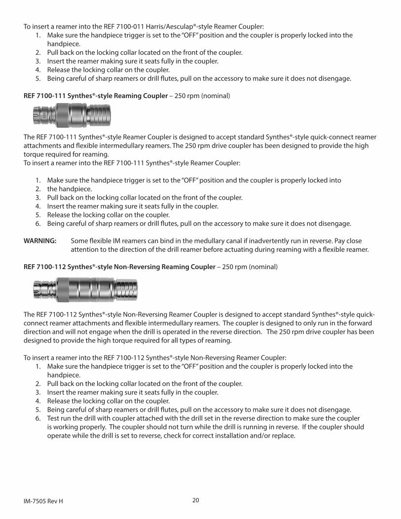
REF 7100-111 Synthes®-style Reaming Coupler – 250 rpm (nominal)
The REF 7100-111 Synthes®-style Reamer Coupler is designed to accept standard Synthes®-style quick-connect reamer attachments and flexible intermedullary reamers. The 250 rpm drive coupler has been designed to provide the high torque required for reaming.To insert a reamer into the REF 7100-111 Synthes®-style Reamer Coupler:
1. Make sure the handpiece trigger is set to the “OFF” position and the coupler is properly locked into 2. the handpiece.3. Pull back on the locking collar located on the front of the coupler. 4. Insert the reamer making sure it seats fully in the coupler.5. Release the locking collar on the coupler.6. Being careful of sharp reamers or drill flutes, pull on the accessory to make sure it does not disengage.
WARNING: Some flexible IM reamers can bind in the medullary canal if inadvertently run in reverse. Pay close attention to the direction of the drill reamer before actuating during reaming with a flexible reamer.
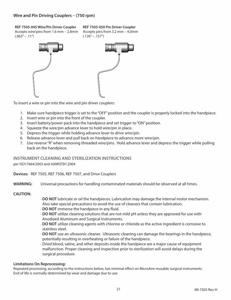
REF 7100-112 Synthes®-style Non-Reversing Reaming Coupler – 250 rpm (nominal)
The REF 7100-112 Synthes®-style Non-Reversing Reamer Coupler is designed to accept standard Synthes®-style quick-connect reamer attachments and flexible intermedullary reamers. The coupler is designed to only run in the forward direction and will not engage when the drill is operated in the reverse direction. The 250 rpm drive coupler has been designed to provide the high torque required for all types of reaming.
To insert a reamer into the REF 7100-112 Synthes®-style Non-Reversing Reamer Coupler:1. Make sure the handpiece trigger is set to the “OFF” position and the coupler is properly locked into the
handpiece.2. Pull back on the locking collar located on the front of the coupler. 3. Insert the reamer making sure it seats fully in the coupler.4. Release the locking collar on the coupler.5. Being careful of sharp reamers or drill flutes, pull on the accessory to make sure it does not disengage.6. Test run the drill with coupler attached with the drill set in the reverse direction to make sure the coupler
is working properly. The coupler should not turn while the drill is running in reverse. If the coupler should operate while the drill is set to reverse, check for correct installation and/or replace.
21 IM-7505 Rev H
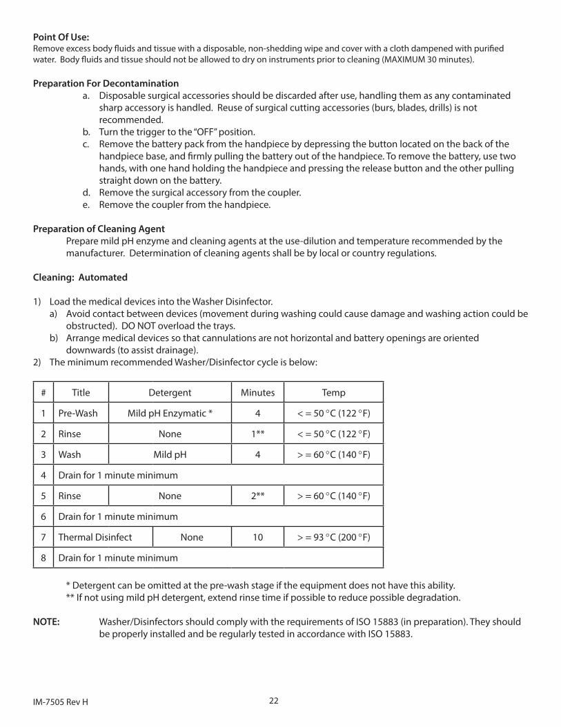
Wire and Pin Driving Couplers – (750 rpm)
REF 7505-045 Wire/Pin Driver CouplerAccepts wire/pins from 1.6 mm – 2.8mm (.063” – .11”)
REF 7505-050 Pin Driver CouplerAccepts pins from 3.2 mm – 4.0mm (.126” – .157”)
To insert a wire or pin into the wire and pin driver couplers:
1. Make sure handpiece trigger is set to the “OFF” position and the coupler is properly locked into the handpiece.2. Insert wire or pin into the front of the coupler.3. Insert battery/power pack into the handpiece and set trigger to “ON” position.4. Squeeze the wire/pin advance lever to hold wire/pin in place.5. Depress the trigger while holding advance lever to drive wire/pin.6. Release advance lever and pull back on handpiece to advance more wire/pin.7. Use reverse “R” when removing threaded wire/pins. Hold advance lever and depress the trigger while pulling
back on the handpiece.
INSTRUMENT CLEANING AND STERILIZATION INSTRUCTIONSper ISO17664:2003 and AAMIST81:2004
Devices: REF 7505, REF 7506, REF 7507, and Drive Couplers
WARNING: Universal precautions for handling contaminated materials should be observed at all times.
CAUTION: · DO NOT lubricate or oil the handpieces. Lubrication may damage the internal motor mechanism. Also take special precautions to avoid the use of cleaners that contain lubrication. · DO NOT immerse the handpiece in any fluid. · DO NOT utilize cleaning solutions that are not mild pH unless they are approved for use with Anodized Aluminum and Surgical Instruments. · DO NOT utilize cleaning agents with chlorine or chloride as the active ingredient is corrosive to stainless steel. · DO NOT use an ultrasonic cleaner. Ultrasonic cleaning can damage the bearings in the handpiece, potentially resulting in overheating or failure of the handpiece. · Dried blood, saline, and other deposits inside the handpiece are a major cause of equipment malfunction. Proper cleaning and inspection prior to sterilization will avoid delays during the surgical procedure.
Limitations On Reprocessing:Repeated processing, according to the instructions below, has minimal effect on MicroAire reusable surgical instruments. End of life is normally determined by wear and damage due to use.
22IM-7505 Rev H
Point Of Use:Remove excess body fluids and tissue with a disposable, non-shedding wipe and cover with a cloth dampened with purified water. Body fluids and tissue should not be allowed to dry on instruments prior to cleaning (MAXIMUM 30 minutes).
Preparation For Decontamination a. Disposable surgical accessories should be discarded after use, handling them as any contaminated
sharp accessory is handled. Reuse of surgical cutting accessories (burs, blades, drills) is not recommended.
b. Turn the trigger to the “OFF” position.c. Remove the battery pack from the handpiece by depressing the button located on the back of the
handpiece base, and firmly pulling the battery out of the handpiece. To remove the battery, use two hands, with one hand holding the handpiece and pressing the release button and the other pulling straight down on the battery.
d. Remove the surgical accessory from the coupler.e. Remove the coupler from the handpiece.
Preparation of Cleaning AgentPrepare mild pH enzyme and cleaning agents at the use-dilution and temperature recommended by the manufacturer. Determination of cleaning agents shall be by local or country regulations.
Cleaning: Automated
1) Load the medical devices into the Washer Disinfector.a) Avoid contact between devices (movement during washing could cause damage and washing action could be
obstructed). DO NOT overload the trays.b) Arrange medical devices so that cannulations are not horizontal and battery openings are oriented
downwards (to assist drainage).2) The minimum recommended Washer/Disinfector cycle is below:
# Title Detergent Minutes Temp
1 Pre-Wash Mild pH Enzymatic * 4 < = 50 °C (122 °F)
2 Rinse None 1** < = 50 °C (122 °F)
3 Wash Mild pH 4 > = 60 °C (140 °F)
4 Drain for 1 minute minimum
5 Rinse None 2** > = 60 °C (140 °F)
6 Drain for 1 minute minimum
7 Thermal Disinfect None 10 > = 93 °C (200 °F)
8 Drain for 1 minute minimum
* Detergent can be omitted at the pre-wash stage if the equipment does not have this ability.** If not using mild pH detergent, extend rinse time if possible to reduce possible degradation.
NOTE: Washer/Disinfectors should comply with the requirements of ISO 15883 (in preparation). They should be properly installed and be regularly tested in accordance with ISO 15883.
23 IM-7505 Rev H
Cleaning: Manual
1. Clean the device immediately with warm water (> 60 °C / 140 °F), mild pH enzymatic detergent, and a soft brush. Scrub the handpiece with the brush, paying close attention to instrument crevices. Make sure the handpiece is held upright as often as possible during cleaning and rinsing to keep moisture away from the battery receptacle.
2. Use a cannulation brush on cannulation of the REF 7505 drill reamer and cannulated drive couplers. a. Clean the cannulated shaft of the wire/pin drivers with the small cylindrical wire driver cannulation
brush (9600-063), or equivalent brush or pipe-cleaner.b. Continue to brush clean the cannulation in the handpiece and drive couplers until the brush comes
out clean and no longer contains signs of blood or tissue.3. Rinse thoroughly under running water (< 50 °C / 122 °F) for a minimum of 2 minutes.4. Clean the handpiece thoroughly with warm water (> 60 °C / 140 °F), mild pH detergent, and a soft brush.
Scrub the handpiece with the brush, paying close attention to the instrument crevices. 5. Flush the lumens of instruments and the nose of drills and wire drivers with a Water-Pik or similar device.
Flushing removes blood, debris, and saline deposits. 6. Rinse all items thoroughly under running water (< 50 °C / 122 °F) for a minimum of 2 minutes.
If possible, use distilled water for the final rinse.
Disinfection:Disinfection is only acceptable as an adjunct to full terminal sterilization for reusable surgical instruments. See sterilization section below.
Drying:Wipe off any water from the handpiece with a soft lint-free towel. An air gun can also be used to dry the handpiece.
Maintenance, Inspection and Function Testing:
1. Carefully inspect each device to ensure that all visible blood and soil has been removed.2. Visually inspect for damage and/or wear.3. Check the action of moving parts to ensure smooth operation throughout the intended range of motion.4. Where instruments form part of a larger assembly, check that the devices assemble with mating components
NOTE: If concerns are noted that may compromise the function of the device, please contact your MicroAire representative.
Accidental ImmersionIf a handpiece is accidentally immersed in saline, disinfectant, cleaning fluid or any other corrosive substance, take the following steps to save the handpiece:
a. Totally immerse the handpiece in distilled water for 1 minute to dilute the corrosive fluid. DO NOT allow water to dry in the handpiece.
b. Immediately after soaking, steam sterilize in a pre vacuum sterilizer at 270°F (132°C) for 4 minutes followed by a minimum drying time of 8 minutes. Sterilizing will dry out the handpiece, avoid rusting, and prevent contamination from collecting in the motor.
c. Return the handpiece to MicroAire or MicroAire authorized service center for service.
Packaging:
1. Single Instruments – A standard medical grade steam sterilization wrap may be used. Ensure that the wrap is large enough to contain the instrument without stressing the packaging. (ANSI/AAMI ST46-1993)
2. Sets of Instruments – sets of instruments may be loaded into dedicated instrument trays or general purpose sterilization trays for sterilization. If applicable, use standard medical grade steam sterilization wrap following the AAMI double wrap method (ANSI/AAMI ST46-1993)
24IM-7505 Rev H
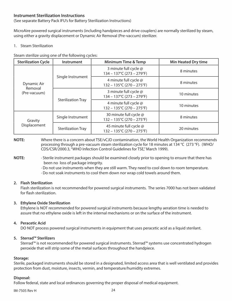
Instrument Sterilization Instructions(See separate Battery Pack IFU’s for Battery Sterilization Instructions)
MicroAire powered surgical instruments (including handpieces and drive couplers) are normally sterilized by steam, using either a gravity displacement or Dynamic Air Removal (Pre-vaccum) sterilizer.
1. Steam Sterilization
Steam sterilize using one of the following cycles:
Sterilization Cycle Instrument Minimum Time & Temp Min Heated Dry time
Dynamic Air Removal
(Pre-vacuum)
Single Instrument
3 minute full cycle @ 134 – 137°C (273 – 279°F) 8 minutes
4 minute full cycle @ 132 – 135°C (270 – 275°F) 8 minutes
Sterilization Tray
3 minute full cycle @ 134 – 137°C (273 – 279°F) 10 minutes
4 minute full cycle @ 132 – 135°C (270 – 275°F) 10 minutes
Gravity Displacement
Single Instrument 30 minute full cycle @ 132 – 135°C (270 – 275°F) 8 minutes
Sterilization Tray 45 minute full cycle @ 132 – 135°C (270 – 275°F) 20 minutes
NOTE: Where there is a concern about TSE/vCJD contamination, the World Health Organization recommends processing through a pre-vacuum steam sterilization cycle for 18 minutes at 134 °C (273 °F). (WHO/ CDS/CSR/2000.3, “WHO Infection Control Guidelines for TSE,” March 1999).
NOTE: · Sterile instrument packages should be examined closely prior to opening to ensure that there has been no loss of package integrity.
· Do not use instruments when they are still warm. They need to cool down to room temperature.· Do not soak instruments to cool them down nor wrap cold towels around them.
2. Flash SterilizationFlash sterilization is not recommended for powered surgical instruments. The series 7000 has not been validated for flash sterilization.
3. Ethylene Oxide SterilizationEthylene is NOT recommended for powered surgical instruments because lengthy aeration time is needed to assure that no ethylene oxide is left in the internal mechanisms or on the surface of the instrument.
4. Peracetic AcidDO NOT process powered surgical instruments in equipment that uses peracetic acid as a liquid sterilant.
5. Sterrad™ SterilizersSterrad™ is not recommended for powered surgical instruments. Sterrad™ systems use concentrated hydrogen peroxide that will strip some of the metal surfaces throughout the handpiece.
Storage:Sterile, packaged instruments should be stored in a designated, limited access area that is well ventilated and provides protection from dust, moisture, insects, vermin, and temperature/humidity extremes.
Disposal:Follow federal, state and local ordinances governing the proper disposal of medical equipment.
25 IM-7505 Rev H
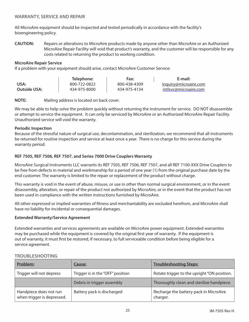
WARRANTY, SERVICE AND REPAIR
All MicroAire equipment should be inspected and tested periodically in accordance with the facility’s bioengineering policy.
CAUTION: Repairs or alterations to MicroAire products made by anyone other than MicroAire or an Authorized MicroAire Repair Facility will void that product’s warranty, and the customer will be responsible for any costs related to returning the product to working condition.
MicroAire Repair ServiceIf a problem with your equipment should arise, contact MicroAire Customer Service:
Telephone: Fax: E-mail:USA: 800-722-0822 800-438-4309 [email protected] USA: 434-975-8000 434-975-4134 [email protected]
NOTE: Mailing address is located on back cover.
We may be able to help solve the problem quickly without returning the instrument for service. DO NOT disassemble or attempt to service the equipment. It can only be serviced by MicroAire or an Authorized MicroAire Repair Facility. Unauthorized service will void the warranty.
Periodic InspectionBecause of the stressful nature of surgical use, decontamination, and sterilization, we recommend that all instruments be returned for routine inspection and service at least once a year. There is no charge for this service during the warranty period.
REF 7505, REF 7506, REF 7507, and Series 7000 Drive Couplers Warranty
MicroAire Surgical Instruments LLC warrants its REF 7505, REF 7506, REF 7507, and all REF 7100-XXX Drive Couplers to be free from defects in material and workmanship for a period of one year (1) from the original purchase date by the end customer. The warranty is limited to the repair or replacement of the product without charge.
This warranty is void in the event of abuse, misuse, or use in other than normal surgical environment, or in the event disassembly, alteration, or repair of the product not authorized by MicroAire, or in the event that the product has not been used in compliance with the written instructions furnished by MicroAire.
All other expressed or implied warranties of fitness and merchantability are excluded herefrom, and MicroAire shall have no liability for incidental or consequential damages.
Extended Warranty/Service Agreement
Extended warranties and services agreements are available on MicroAire power equipment. Extended warranties may be purchased while the equipment is covered by the original first year of warranty. If the equipment is out of warranty, it must first be restored, if necessary, to full serviceable condition before being eligible for a service agreement.
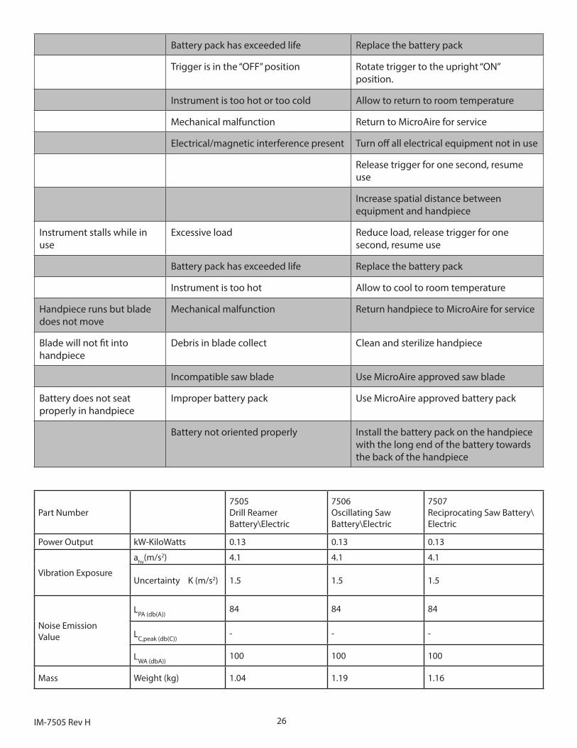
TROUBLESHOOTING
Problem: Cause: Troubleshooting Steps:
Trigger will not depress Trigger is in the “OFF” position Rotate trigger to the upright “ON position.
Debris in trigger assembly Thoroughly clean and sterilize handpiece.
Handpiece does not run when trigger is depressed.
Battery pack is discharged Recharge the battery pack in MicroAire charger.
26IM-7505 Rev H
Battery pack has exceeded life Replace the battery pack
Trigger is in the “OFF” position Rotate trigger to the upright “ON” position.
Instrument is too hot or too cold Allow to return to room temperature
Mechanical malfunction Return to MicroAire for service
Electrical/magnetic interference present Turn off all electrical equipment not in use
Release trigger for one second, resume use
Increase spatial distance between equipment and handpiece
Instrument stalls while in use
Excessive load Reduce load, release trigger for one second, resume use
Battery pack has exceeded life Replace the battery pack
Instrument is too hot Allow to cool to room temperature
Handpiece runs but blade does not move
Mechanical malfunction Return handpiece to MicroAire for service
Blade will not fit into handpiece
Debris in blade collect Clean and sterilize handpiece
Incompatible saw blade Use MicroAire approved saw blade
Battery does not seat properly in handpiece
Improper battery pack Use MicroAire approved battery pack
Battery not oriented properly Install the battery pack on the handpiece with the long end of the battery towards the back of the handpiece
Part Number7505Drill Reamer Battery\Electric
7506Oscillating Saw Battery\Electric
7507Reciprocating Saw Battery\Electric
Power Output kW-KiloWatts 0.13 0.13 0.13
Vibration Exposure
ahv(m/s2) 4.1 4.1 4.1
Uncertainty K (m/s2) 1.5 1.5 1.5
Noise Emission Value
LPA (db(A))84 84 84
LC,peak (db(C))- - -
LWA (dbA))100 100 100
Mass Weight (kg) 1.04 1.19 1.16
27 IM-7505 Rev H
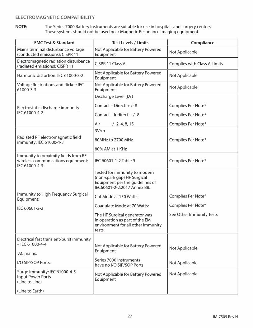
ELECTROMAGNETIC COMPATIBILITY
NOTE: The Series 7000 Battery Instruments are suitable for use in hospitals and surgery centers. These systems should not be used near Magnetic Resonance Imaging equipment.
EMC Test & Standard Test Levels / Limits ComplianceMains terminal disturbance voltage (conducted emissions): CISPR 11
Not Applicable for Battery Powered Equipment Not Applicable
Electromagnetic radiation disturbance (radiated emissions): CISPR 11 CISPR 11 Class A Complies with Class A Limits
Harmonic distortion: IEC 61000-3-2 Not Applicable for Battery Powered Equipment Not Applicable
Voltage fluctuations and flicker: IEC 61000-3-3
Not Applicable for Battery Powered Equipment Not Applicable
Electrostatic discharge immunity: IEC 61000-4-2
Discharge Level (kV)
Contact – Direct: + /- 8
Contact – Indirect: +/- 8
Air +/- 2, 4, 8, 15
Complies Per Note*
Complies Per Note*
Complies Per Note*
Radiated RF electromagnetic field immunity: IEC 61000-4-3
3V/m
80MHz to 2700 MHz
80% AM at 1 KHz
Complies Per Note*
Immunity to proximity fields from RF wireless communications equipment: IEC 61000-4-3
IEC 60601-1-2 Table 9 Complies Per Note*
Immunity to High Frequency Surgical Equipment:
IEC 60601-2-2
Tested for immunity to modern (non-spark gap) HF Surgical Equipment per the guidelines of IEC60601-2-2:2017 Annex BB.
Cut Mode at 150 Watts:
Coagulate Mode at 70 Watts:
The HF Surgical generator was in operation as part of the EM environment for all other immunity tests.
Complies Per Note*
Complies Per Note*
See Other Immunity Tests
Electrical fast transient/burst immunity – IEC 61000-4-4
AC mains:
I/O SIP/SOP Ports:
Not Applicable for Battery Powered Equipment
Series 7000 Instruments have no I/O SIP/SOP Ports
Not Applicable
Not Applicable
Surge Immunity: IEC 61000-4-5 Input Power Ports (Line to Line)
(Line to Earth)
Not Applicable for Battery Powered Equipment
Not Applicable
28IM-7505 Rev H
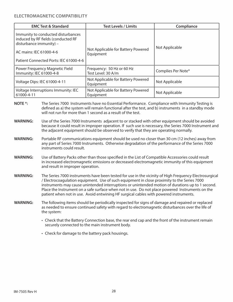
ELECTROMAGNETIC COMPATIBILITY
EMC Test & Standard Test Levels / Limits Compliance
Immunity to conducted disturbances induced by RF fields (conducted RF disturbance immunity) –
AC mains: IEC 61000-4-6
Patient Connected Ports: IEC 61000-4-6
Not Applicable for Battery Powered Equipment
Not Applicable
Power Frequency Magnetic Field Immunity: IEC 61000-4-8
Frequency: 50 Hz or 60 Hz Test Level: 30 A/m Complies Per Note*
Voltage Dips: IEC 61000-4-11 Not Applicable for Battery Powered Equipment Not Applicable
Voltage Interruptions Immunity: IEC 61000-4-11
Not Applicable for Battery Powered Equipment Not Applicable
NOTE *: The Series 7000 Instruments have no Essential Performance. Compliance with Immunity Testing is defined as a) the system will remain functional after the test, and b) instruments in a standby mode will not run for more than 1 second as a result of the test.
WARNING: Use of the Series 7000 Instruments adjacent to or stacked with other equipment should be avoided because it could result in improper operation. If such use is necessary, the Series 7000 Instrument and the adjacent equipment should be observed to verify that they are operating normally.
WARNING: Portable RF communications equipment should be used no closer than 30 cm (12 inches) away from any part of Series 7000 Instruments. Otherwise degradation of the performance of the Series 7000 instruments could result. WARNING: Use of Battery Packs other than those specified in the List of Compatible Accessories could result in increased electromagnetic emissions or decreased electromagnetic immunity of this equipment and result in improper operation. WARNING: The Series 7000 instruments have been tested for use in the vicinity of High Frequency Electrosurgical / Electrocoagulation equipment. Use of such equipment in close proximity to the Series 7000 instruments may cause unintended interruptions or unintended motion of durations up to 1 second. Place the Instrument on a safe surface when not in use. Do not place powered Instruments on the patient when not in use. Avoid entwining HF surgical cables with powered instruments.
WARNING: The following items should be periodically inspected for signs of damage and repaired or replaced as needed to ensure continued safety with regard to electromagnetic disturbances over the life of the system:
• Check that the Battery Connection base, the rear end cap and the front of the instrument remain securely connected to the main instrument body.
• Check for damage to the battery pack housings.

29 IM-7505 Rev H
The following companies are not affiliated with MicroAire Surgical Instruments LLC.
Zimmer® is a registered trademark of Zimmer Biomet. Synthes® is a registered trademark of Depuy Synthes (USA). Sterrad® is a registered trademark of Advanced Surgical Products. Aesculap® is a registered trademark of B. Braun Medical Inc.Jacobs ® is a registered trademark of Jacobs.
©2019 MicroAire Surgical Instruments LLC | IM-7505, Rev. H
MicroAire Surgical Instruments, LLC 3590 Grand Forks Boulevard Charlottesville, Virginia 22911 USA Phone: (800) 722-0822 (434) 975-8000 Order Fax: (800) 648-4309 or (434) 975-4131 www.microaire.com
MediMark Europe 11, rue Emile Zola - BP 2332 F-38033 Grenoble Cedex 2 France
2007


![[ABNT-NBR 7505] - Armazenagem de Petróleo e Seus Derivados](https://img.pdfslide.net/doc/110x75/557201544979599169a14eb6/abnt-nbr-7505-armazenagem-de-petroleo-e-seus-derivados.jpg)