Embed Size (px)
Citation preview
IOM-F -RP
I N S T A L L A T I O N , O P E R A T I O N , M A I N T E N A N C E
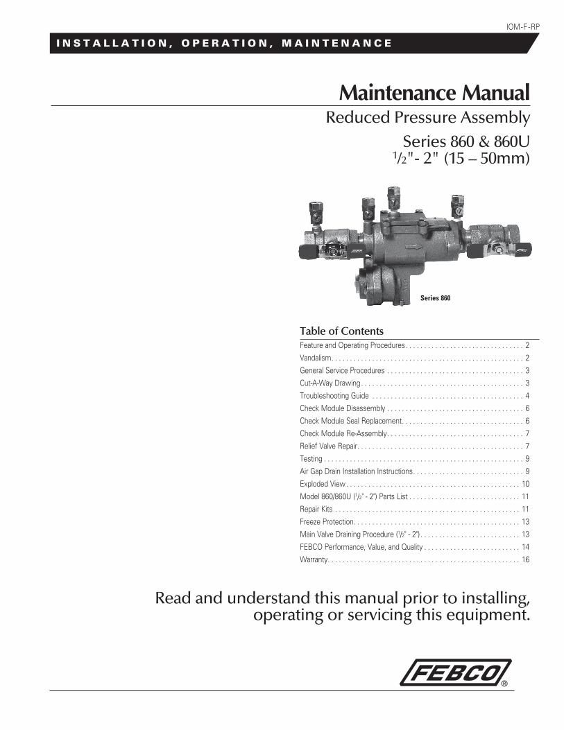
Maintenance ManualReduced Pressure Assembly
Series 860 & 860U 1/2"- 2" (15 – 50mm)
Read and understand this manual prior to installing, operating or servicing this equipment.
Series 860
Table of ContentsFeature and Operating Procedures . . . . . . . . . . . . . . . . . . . . . . . . . . . . . . . . 2
Vandalism . . . . . . . . . . . . . . . . . . . . . . . . . . . . . . . . . . . . . . . . . . . . . . . . . . . . 2
General Service Procedures . . . . . . . . . . . . . . . . . . . . . . . . . . . . . . . . . . . . . 3
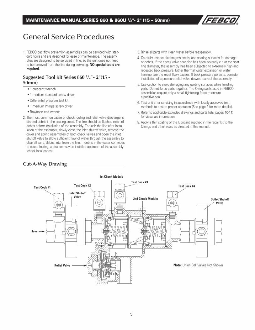
Cut-A-Way Drawing . . . . . . . . . . . . . . . . . . . . . . . . . . . . . . . . . . . . . . . . . . . . 3
Troubleshooting Guide . . . . . . . . . . . . . . . . . . . . . . . . . . . . . . . . . . . . . . . . . 4
Check Module Disassembly . . . . . . . . . . . . . . . . . . . . . . . . . . . . . . . . . . . . . 6
Check Module Seal Replacement . . . . . . . . . . . . . . . . . . . . . . . . . . . . . . . . . 6
Check Module Re-Assembly . . . . . . . . . . . . . . . . . . . . . . . . . . . . . . . . . . . . . 7
Relief Valve Repair . . . . . . . . . . . . . . . . . . . . . . . . . . . . . . . . . . . . . . . . . . . . . 7
Testing . . . . . . . . . . . . . . . . . . . . . . . . . . . . . . . . . . . . . . . . . . . . . . . . . . . . . . 9
Air Gap Drain Installation Instructions . . . . . . . . . . . . . . . . . . . . . . . . . . . . . . 9
Exploded View . . . . . . . . . . . . . . . . . . . . . . . . . . . . . . . . . . . . . . . . . . . . . . . 10
Model 860/860U (1/2" - 2") Parts List . . . . . . . . . . . . . . . . . . . . . . . . . . . . . . 11
Repair Kits . . . . . . . . . . . . . . . . . . . . . . . . . . . . . . . . . . . . . . . . . . . . . . . . . . 11
Freeze Protection . . . . . . . . . . . . . . . . . . . . . . . . . . . . . . . . . . . . . . . . . . . . . 13
Main Valve Draining Procedure (1/2" - 2") . . . . . . . . . . . . . . . . . . . . . . . . . . . 13
FEBCO Performance, Value, and Quality . . . . . . . . . . . . . . . . . . . . . . . . . . 14
Warranty . . . . . . . . . . . . . . . . . . . . . . . . . . . . . . . . . . . . . . . . . . . . . . . . . . . . 16
2
Feature and Operating Procedures
MAINTENANCE MANUAL SERIES 860 & 860U 1/2"- 2" (15 – 50mm)
The FEBCO Reduced Pressure Backflow Preventer Assembly consists of two independently operating, spring loaded check valves with a pressure differential relief valve located between the two checks . The pressure drop across the first check valve is approximately 7 .0 psid with no flow . The relief valve consists of a hydraulically balanced diaphragm with the high pressure side hydraulically connected to the upstream pressure zone . The relief valve remains closed during normal operation . The low pressure side of the diaphragm is spring loaded to force the relief valve open when the pressure drop across the first check and across the dia-phragm reduced to approximately 3 .0 psid . A complete assembly includes two shutoff valves and four test cocks .
VandalismIf the unit is installed where vandalism may be a problem, the assembly should be protected and secured . On 1/2" through 2" (15 – 50mm) units the handles of shutoff valves can be removed to discourage tampering . A protective enclosure can be installed over the unit to discourage van-dals . If an enclosure is used, it should be installed so that adequate clear-ance is available for maintenance and testing . Consult local codes before installing any type of protective enclosure .
3
General Service Procedures
MAINTENANCE MANUAL SERIES 860 & 860U 1/2"- 2" (15 – 50mm)
1 . FEBCO backflow prevention assemblies can be serviced with stan-dard tools and are designed for ease of maintenance . The assem-blies are designed to be serviced in line, so the unit does not need to be removed from the line during servicing . NO special tools are required.
Suggested Tool Kit Series 860 1/2" - 2"(15 - 50mm) •1crescentwrench
•1mediumstandardscrewdriver
•Differentialpressuretestkit
•1mediumPhillipsscrewdriver
•Box/openendwrench
2 . The most common cause of check fouling and relief valve discharge is dirt and debris in the seating areas . The line should be flushed clean of debris before installation of the assembly . To flush the line after instal-lation of the assembly, slowly close the inlet shutoff valve, remove the cover and spring assemblies of both check valves and open the inlet shutoff valve to allow sufficient flow of water through the assembly to clear all sand, debris, etc . from the line . If debris in the water continues to cause fouling, a strainer may be installed upstream of the assembly (check local codes) .
3 . Rinse all parts with clean water before reassembly .
4 . Carefully inspect diaphragms, seals, and seating surfaces for damage or debris . If the check valve seat disc has been severely cut at the seat ring diameter, the assembly has been subjected to extremely high and repeated back pressure . Either thermal water expansion or water hammer are the most likely causes . If back pressure persists, consider installation of a pressure relief valve downstream of the assembly .
5 . Use caution to avoid damaging any guiding surfaces while handling parts . Do not force parts together . The O-ring seals used in FEBCO assemblies require only a small tightening force to ensure a positive seal .
6 . Test unit after servicing in accordance with locally approved test methods to ensure proper operation (See page 9 for more details) .
7 . Refer to applicable exploded drawings and parts lists (pages 10-11) for visual aid information .
8 . Apply a thin coating of the lubricant supplied in the repair kit to the O-rings and other seals as directed in this manual .
Test Cock #3Test Cock #4
2nd Check Module
Relief Valve
Test Cock #1
Inlet Shutoff Valve
Outlet Shutoff Valve
1st Check Module
Flow
Test Cock #2
Note: Union Ball Valves Not Shown
Cut-A-Way Drawing
4
MAINTENANCE MANUAL SERIES 860 & 860U 1/2"- 2" (15 – 50mm)
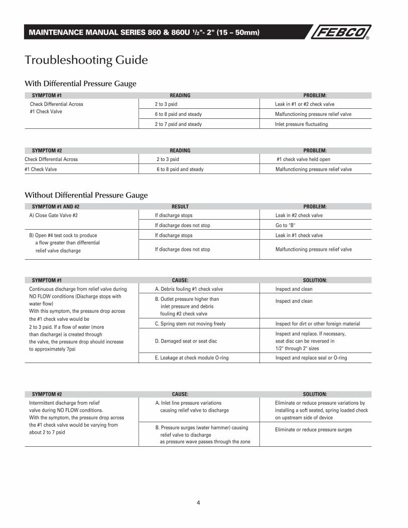
Troubleshooting Guide
With Differential Pressure Gauge SyMpTOM #1 ReadIng pRObleM:
Check Differential Across 2 to 3 psid Leak in #1 or #2 check valve
#1 Check Valve 6 to 8 psid and steady Malfunctioning pressure relief valve
2 to 7 psid and steady Inlet pressure fluctuating
SyMpTOM #2 ReadIng pRObleM:
Check Differential Across 2 to 3 psid #1 check valve held open
#1 Check Valve 6 to 8 psid and steady Malfunctioning pressure relief valve
SyMpTOM #1 CauSe: SOluTIOn:
Continuous discharge from relief valve during A. Debris fouling #1 check valve Inspect and clean
NO FLOW conditions (Discharge stops with B. Outlet pressure higher than Inspect and clean water flow) inlet pressure and debris With this symptom, the pressure drop across fouling #2 check valve
the #1 check valve would be
C. Spring stem not moving freely Inspect for dirt or other foreign material
2 to 3 psid. If a flow of water (more
Inspect and replace. If necessary,
than discharge) is created through D. Damaged seat or seat disc seat disc can be reversed in
the valve, the pressure drop should increase
1/2" through 2" sizes
to approximately 7psi
E. Leakage at check module O-ring Inspect and replace seal or O-ring
SyMpTOM #2 CauSe: SOluTIOn:
Intermittent discharge from relief A. Inlet line pressure variations Eliminate or reduce pressure variations by valve during NO FLOW conditions. causing relief valve to discharge installing a soft seated, spring loaded check With the symptom, the pressure drop across on upstream side of device
the #1 check valve would be varying from B. Pressure surges (water hammer) causing Eliminate or reduce pressure surges about 2 to 7 psid relief valve to discharge as pressure wave passes through the zone
Without Differential Pressure Gauge SyMpTOM #1 and #2 ReSulT pRObleM:
A) Close Gate Valve #2 If discharge stops Leak in #2 check valve
If discharge does not stop Go to "B"
B) Open #4 test cock to produce If discharge stops Leak in #1 check valve
a flow greater than differential If discharge does not stop
Malfunctioning pressure relief valve
relief valve discharge
5
MAINTENANCE MANUAL SERIES 860 & 860U 1/2"- 2" (15 – 50mm)
Troubleshooting Guide (Continued)
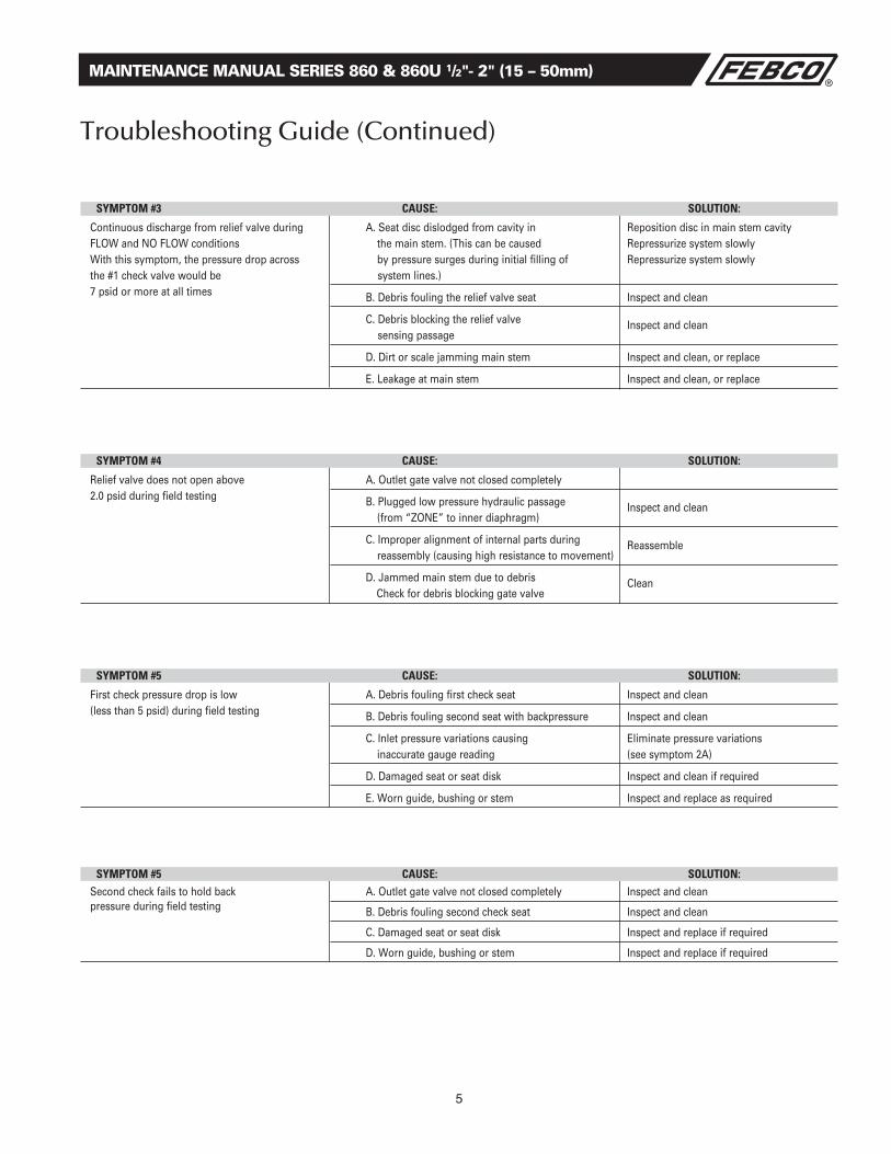
SyMpTOM #3 CauSe: SOluTIOn:
Continuous discharge from relief valve during A. Seat disc dislodged from cavity in Reposition disc in main stem cavity FLOW and NO FLOW conditions the main stem. (This can be caused Repressurize system slowly With this symptom, the pressure drop across by pressure surges during initial filling of Repressurize system slowly the #1 check valve would be system lines.)
7 psid or more at all times B. Debris fouling the relief valve seat Inspect and clean
C. Debris blocking the relief valve Inspect and clean sensing passage
D. Dirt or scale jamming main stem Inspect and clean, or replace
E. Leakage at main stem Inspect and clean, or replace
SyMpTOM #4 CauSe: SOluTIOn:
Relief valve does not open above A. Outlet gate valve not closed completely
2.0 psid during field testing B. Plugged low pressure hydraulic passage Inspect and clean (from “ZONE” to inner diaphragm)
C. Improper alignment of internal parts during Reassemble reassembly (causing high resistance to movement)
D. Jammed main stem due to debris Clean Check for debris blocking gate valve
SyMpTOM #5 CauSe: SOluTIOn:
First check pressure drop is low A. Debris fouling first check seat Inspect and clean
(less than 5 psid) during field testing B. Debris fouling second seat with backpressure Inspect and clean
C. Inlet pressure variations causing Eliminate pressure variations inaccurate gauge reading (see symptom 2A)
D. Damaged seat or seat disk Inspect and clean if required
E. Worn guide, bushing or stem Inspect and replace as required
SyMpTOM #5 CauSe: SOluTIOn: Second check fails to hold back A. Outlet gate valve not closed completely Inspect and clean
pressure during field testing B. Debris fouling second check seat Inspect and clean
C. Damaged seat or seat disk Inspect and replace if required
D. Worn guide, bushing or stem Inspect and replace if required
Check Module Seal ReplacementBoth check assemblies are disassembled and reassembled in the same manner . To service the checks, you may replace the check modules with new ones by using check module assembly kits available from FEBCO . Or, you may also replace the rubber components in the check modules by using the replacement rubber parts kits available from FEBCO . For details on parts and kits, please see pages 10 - 12 .
1 . To disassemble, grasp the seat section (Item 3) in one hand and the guide section (Item 7) in the other hand and then rotate in a counter clock wise direction (approx . 1/8 turn) until the two parts disengage .
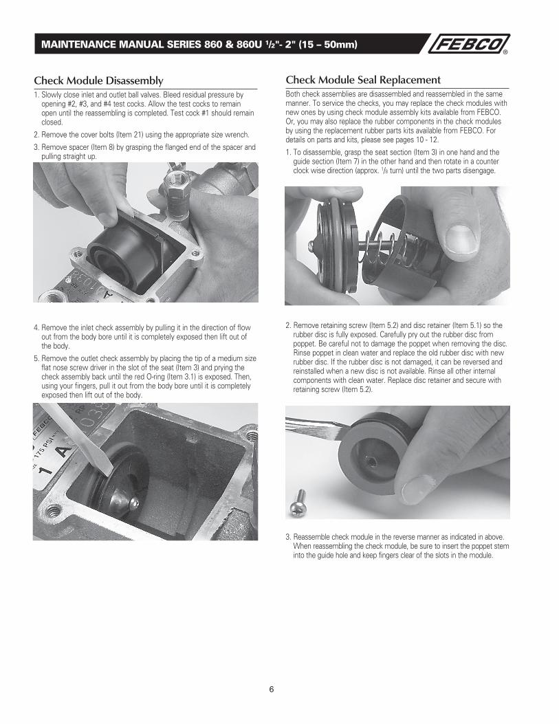
2 . Remove retaining screw (Item 5 .2) and disc retainer (Item 5 .1) so the rubber disc is fully exposed . Carefully pry out the rubber disc from poppet . Be careful not to damage the poppet when removing the disc . Rinse poppet in clean water and replace the old rubber disc with new rubber disc . If the rubber disc is not damaged, it can be reversed and reinstalled when a new disc is not available . Rinse all other internal components with clean water . Replace disc retainer and secure with retaining screw (Item 5 .2) .
3 . Reassemble check module in the reverse manner as indicated in above . When reassembling the check module, be sure to insert the poppet stem into the guide hole and keep fingers clear of the slots in the module .
Check Module Disassembly1 . Slowly close inlet and outlet ball valves . Bleed residual pressure by
opening #2, #3, and #4 test cocks . Allow the test cocks to remain open until the reassembling is completed . Test cock #1 should remain closed .
2 . Remove the cover bolts (Item 21) using the appropriate size wrench .
3 . Remove spacer (Item 8) by grasping the flanged end of the spacer and pulling straight up .
4 . Remove the inlet check assembly by pulling it in the direction of flow out from the body bore until it is completely exposed then lift out of the body .
5 . Remove the outlet check assembly by placing the tip of a medium size flat nose screw driver in the slot of the seat (Item 3) and prying the check assembly back until the red O-ring (Item 3 .1) is exposed . Then, using your fingers, pull it out from the body bore until it is completely exposed then lift out of the body .
6
MAINTENANCE MANUAL SERIES 860 & 860U 1/2"- 2" (15 – 50mm)
7
MAINTENANCE MANUAL SERIES 860 & 860U 1/2"- 2" (15 – 50mm)
Check Module Re-AssemblyUse reverse procedure for assembly with the following special instructions .
1 . Inspect the check module O-ring (Item 3 .1) for damage and replace if necessary . To ease assembly, apply a thin coating of supplied lubricant to the O-ring (Item 3 .1) prior to installing in body . CAUTION: Excess lubricant may cause foreign debris to collect on internal components which could foul the check assembly and result in a test failure .
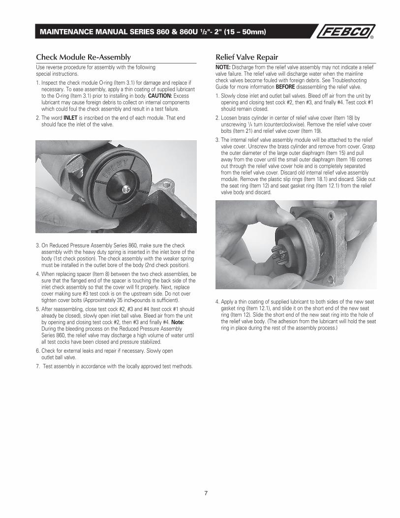
2 . The word INLET is inscribed on the end of each module . That end should face the inlet of the valve .
3 . On Reduced Pressure Assembly Series 860, make sure the check assembly with the heavy duty spring is inserted in the inlet bore of the body (1st check position) . The check assembly with the weaker spring must be installed in the outlet bore of the body (2nd check position) .
4 . When replacing spacer (Item 8) between the two check assemblies, be sure that the flanged end of the spacer is touching the back side of the inlet check assembly so that the cover will fit properly . Next, replace cover making sure #3 test cock is on the upstream side . Do not over tighten cover bolts (Approximately 35 inch•pounds is sufficient) .
5 . After reassembling, close test cock #2, #3 and #4 (test cock #1 should already be closed), slowly open inlet ball valve . Bleed air from the unit by opening and closing test cock #2, then #3 and finally #4 . Note: During the bleeding process on the Reduced Pressure Assembly Series 860, the relief valve may discharge a high volume of water until all test cocks have been closed and pressure stabilized .
6 . Check for external leaks and repair if necessary . Slowly open outlet ball valve .
7 . Test assembly in accordance with the locally approved test methods .
Relief Valve RepairNOTE: Discharge from the relief valve assembly may not indicate a relief valve failure . The relief valve will discharge water when the mainline check valves become fouled with foreign debris . See Troubleshooting Guide for more information BEFORE disassembling the relief valve .
1 . Slowly close inlet and outlet ball valves . Bleed off air from the unit by opening and closing test cock #2, then #3, and finally #4 . Test cock #1 should remain closed .
2 . Loosen brass cylinder in center of relief valve cover (Item 18) by unscrewing 1/4 turn (counterclockwise) . Remove the relief valve cover bolts (Item 21) and relief valve cover (Item 19) .
3 . The internal relief valve assembly module will be attached to the relief valve cover . Unscrew the brass cylinder and remove from cover . Grasp the outer diameter of the large outer diaphragm (Item 15) and pull away from the cover until the small outer diaphragm (Item 16) comes out through the relief valve cover hole and is completely separated from the relief valve cover . Discard old internal relief valve assembly module . Remove the plastic slip rings (Item 18 .1) and discard . Slide out the seat ring (Item 12) and seat gasket ring (Item 12 .1) from the relief valve body and discard .
4 . Apply a thin coating of supplied lubricant to both sides of the new seat gasket ring (Item 12 .1), and slide it on the short end of the new seat ring (Item 12) . Slide the short end of the new seat ring into the hole of the relief valve body . (The adhesion from the lubricant will hold the seat ring in place during the rest of the assembly process .)
8
MAINTENANCE MANUAL SERIES 860 & 860U 1/2"- 2" (15 – 50mm)
Relief Valve Repair - continued5 . Before installing the new internal relief valve assembly module, apply
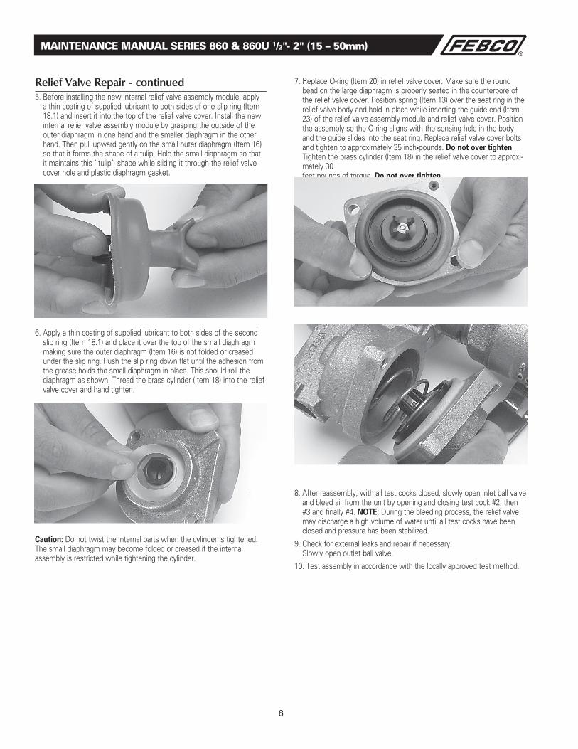
a thin coating of supplied lubricant to both sides of one slip ring (Item 18 .1) and insert it into the top of the relief valve cover . Install the new internal relief valve assembly module by grasping the outside of the outer diaphragm in one hand and the smaller diaphragm in the other hand . Then pull upward gently on the small outer diaphragm (Item 16) so that it forms the shape of a tulip . Hold the small diaphragm so that it maintains this “tulip” shape while sliding it through the relief valve cover hole and plastic diaphragm gasket .
6 . Apply a thin coating of supplied lubricant to both sides of the second slip ring (Item 18 .1) and place it over the top of the small diaphragm making sure the outer diaphragm (Item 16) is not folded or creased under the slip ring . Push the slip ring down flat until the adhesion from the grease holds the small diaphragm in place . This should roll the diaphragm as shown . Thread the brass cylinder (Item 18) into the relief valve cover and hand tighten .
Caution: Do not twist the internal parts when the cylinder is tightened . The small diaphragm may become folded or creased if the internal assembly is restricted while tightening the cylinder .
7 . Replace O-ring (Item 20) in relief valve cover . Make sure the round bead on the large diaphragm is properly seated in the counterbore of the relief valve cover . Position spring (Item 13) over the seat ring in the relief valve body and hold in place while inserting the guide end (Item 23) of the relief valve assembly module and relief valve cover . Position the assembly so the O-ring aligns with the sensing hole in the body and the guide slides into the seat ring . Replace relief valve cover bolts and tighten to approximately 35 inch•pounds . Do not over tighten . Tighten the brass cylinder (Item 18) in the relief valve cover to approxi-mately 30 feet pounds of torque . Do not over tighten .
8 . After reassembly, with all test cocks closed, slowly open inlet ball valve and bleed air from the unit by opening and closing test cock #2, then #3 and finally #4 . NOTE: During the bleeding process, the relief valve may discharge a high volume of water until all test cocks have been closed and pressure has been stabilized .
9 . Check for external leaks and repair if necessary . Slowly open outlet ball valve .
10 . Test assembly in accordance with the locally approved test method .
9
MAINTENANCE MANUAL SERIES 860 & 860U 1/2"- 2" (15 – 50mm)
TestingAll mechanical devices should be inspected on a regular basis to ensure they are working correctly . The assembly should be tested at time of initial installation, after servicing or maintenance, and at least annually thereafter . Acceptable test procedures are published by Foundation for Cross-Connection Control and Hydraulic Research at the University of Southern California (USC), The American Water Works Association (AWWA), The American Society of Sanitary Engineering (ASSE Series 5000)andtheCanadianStandardsAssociation(CAN/CSAB64•10).Pleaseconsult the regulatory authority in your area for more specific information .
Air Gap Drain Installation Instructions1 . Before installation check local codes . This type of drain may not be
approved for use in some areas .
CAUTION: This drain is intended to catch moderate relief valve discharges due to line pressure fluctuations and minor check valve fouling. Under certain conditions relief valves can discharge water at rates greater than the air gap drain capacity.
2 . If installed indoors, the assembly should be installed near a floor drain sized to adequately handle discharge . A Strainer before the backflow assembly is strongly suggested on indoor installation .
3 . After installation of backflow assembly and piping, attach drain funnel to relief as shown, using self tapping screws provided in kit to join drain funnel halves together, making sure that the slots in the drain fun-nel are located over tabs on relief valve port .
Note: Discharge of drain funnel is a slip fit design . Drain funnel was not designed to, nor is it able to support drainpipe weight .
plaSTIC MeTal ValVe SIze paRT nO. paRT nO.
1/2" 905358 905532
3/4" 905358 905532
1" 905358 905532
11/4" 905359 905533
11/2" 905359 905533
2" 905359 905533
Air Gap Part Number
10
MAINTENANCE MANUAL SERIES 860 & 860U 1/2"- 2" (15 – 50mm)
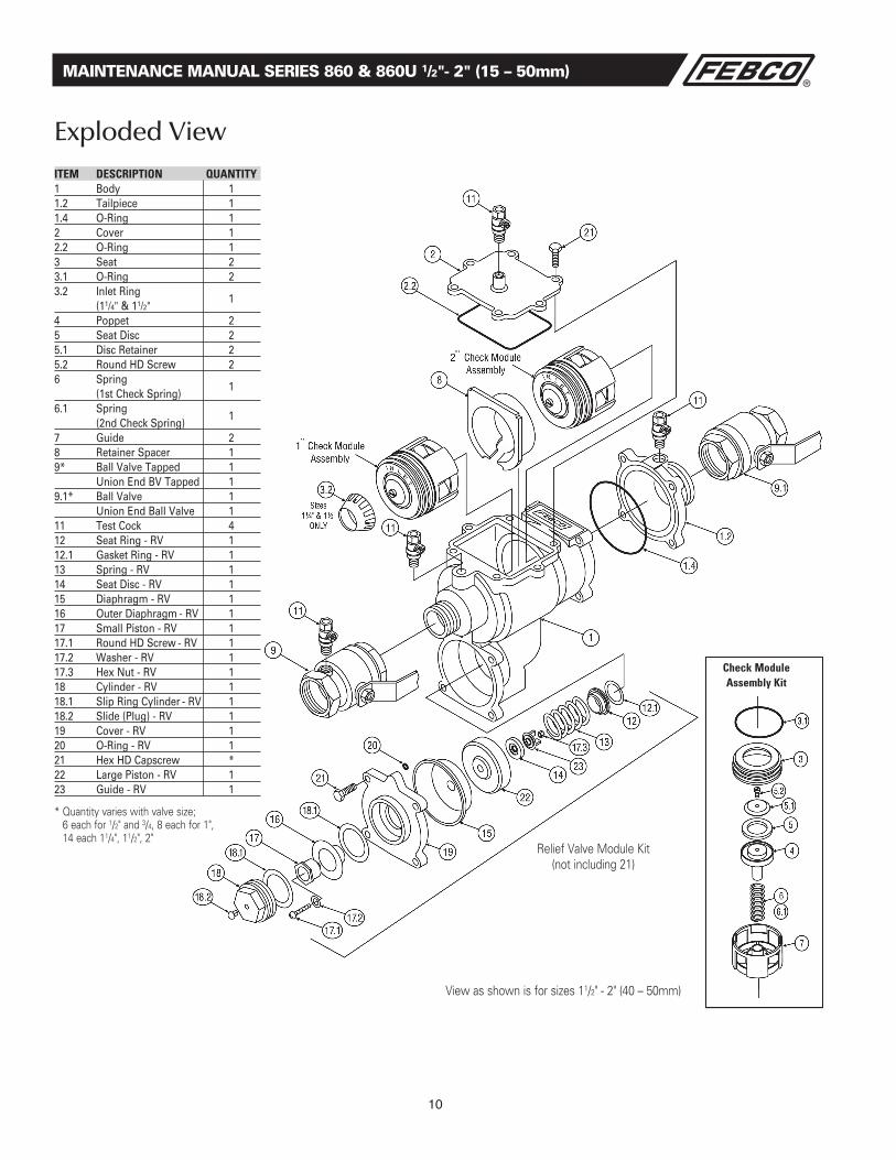
Exploded View
View as shown is for sizes 11/2" - 2" (40 – 50mm)
Relief Valve Module Kit(not including 21)
* Quantity varies with valve size; 6 each for 1/2" and 3/4, 8 each for 1", 14 each 11/4", 11/2", 2"
Check Moduleassembly Kit
ITeM deSCRIpTIOn quanTITy1 Body 11.2 Tailpiece 11.4 O-Ring 12 Cover 12.2 O-Ring 13 Seat 23.1 O-Ring 23.2 Inlet Ring
1
(11/4" & 11/2"4 Poppet 25 Seat Disc 25.1 Disc Retainer 25.2 Round HD Screw 26 Spring
1
(1st Check Spring)6.1 Spring
1
(2nd Check Spring) 7 Guide 28 Retainer Spacer 19* Ball Valve Tapped 1 Union End BV Tapped 19.1* Ball Valve 1 Union End Ball Valve 111 Test Cock 412 Seat Ring - RV 112.1 Gasket Ring - RV 113 Spring - RV 114 Seat Disc - RV 115 Diaphragm - RV 116 Outer Diaphragm - RV 117 Small Piston - RV 117.1 Round HD Screw - RV 117.2 Washer - RV 117.3 Hex Nut - RV 118 Cylinder - RV 118.1 Slip Ring Cylinder - RV 118.2 Slide (Plug) - RV 119 Cover - RV 120 O-Ring - RV 121 Hex HD Capscrew *22 Large Piston - RV 123 Guide - RV 1
11
MAINTENANCE MANUAL SERIES 860 & 860U 1/2"- 2" (15 – 50mm)
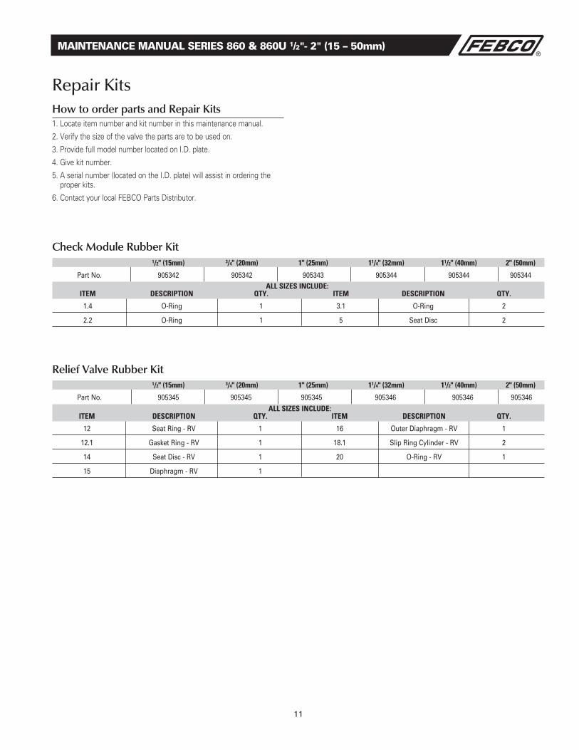
Repair KitsHow to order parts and Repair Kits1 . Locate item number and kit number in this maintenance manual .
2 . Verify the size of the valve the parts are to be used on .
3 . Provide full model number located on I .D . plate .
4 . Give kit number .
5 . A serial number (located on the I .D . plate) will assist in ordering the proper kits .
6 . Contact your local FEBCO Parts Distributor .
Check Module Rubber Kit 1/2" (15mm) 3/4" (20mm) 1" (25mm) 11/4" (32mm) 11/2" (40mm) 2" (50mm)
Part No. 905342 905342 905343 905344 905344 905344 all SIzeS InClude: ITeM deSCRIpTIOn qTy. ITeM deSCRIpTIOn qTy.
1.4 O-Ring 1 3.1 O-Ring 2
2.2 O-Ring 1 5 Seat Disc 2
Relief Valve Rubber Kit 1/2" (15mm) 3/4" (20mm) 1" (25mm) 11/4" (32mm) 11/2" (40mm) 2" (50mm)
Part No. 905345 905345 905345 905346 905346 905346 all SIzeS InClude: ITeM deSCRIpTIOn qTy. ITeM deSCRIpTIOn qTy.
12 Seat Ring - RV 1 16 Outer Diaphragm - RV 1
12.1 Gasket Ring - RV 1 18.1 Slip Ring Cylinder - RV 2
14 Seat Disc - RV 1 20 O-Ring - RV 1
15 Diaphragm - RV 1
12
MAINTENANCE MANUAL SERIES 860 & 860U 1/2"- 2" (15 – 50mm)
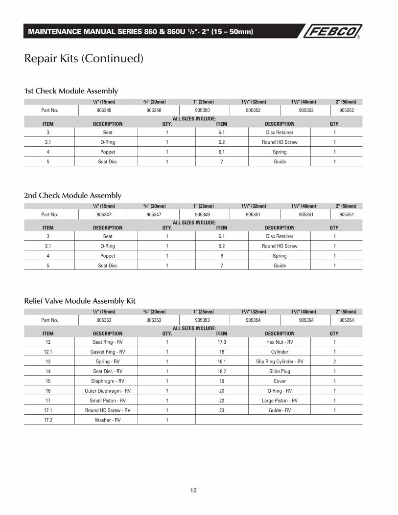
Repair Kits (Continued)
Relief Valve Module Assembly Kit 1/2" (15mm) 3/4" (20mm) 1" (25mm) 11/4" (32mm) 11/2" (40mm) 2" (50mm)
Part No. 905353 905353 905353 905354 905354 905354
all SIzeS InClude: ITeM deSCRIpTIOn qTy. ITeM deSCRIpTIOn qTy.
12 Seat Ring - RV 1 17.3 Hex Nut - RV 1
12.1 Gasket Ring - RV 1 18 Cylinder 1
13 Spring - RV 1 18.1 Slip Ring Cylinder - RV 2
14 Seat Disc - RV 1 18.2 Slide Plug 1
15 Diaphragm - RV 1 19 Cover 1
16 Outer Diaphragm - RV 1 20 O-Ring - RV 1
17 Small Piston - RV 1 22 Large Piston - RV 1
17.1 Round HD Screw - RV 1 23 Guide - RV 1
17.2 Washer - RV 1
2nd Check Module Assembly 1/2" (15mm) 3/4" (20mm) 1" (25mm) 11/4" (32mm) 11/2" (40mm) 2" (50mm)
Part No. 905347 905347 905349 905351 905351 905351
all SIzeS InClude: ITeM deSCRIpTIOn qTy. ITeM deSCRIpTIOn qTy.
3 Seat 1 5.1 Disc Retainer 1
3.1 O-Ring 1 5.2 Round HD Screw 1
4 Poppet 1 6 Spring 1
5 Seat Disc 1 7 Guide 1
1st Check Module Assembly 1/2" (15mm) 3/4" (20mm) 1" (25mm) 11/4" (32mm) 11/2" (40mm) 2" (50mm)
Part No. 905348 905348 905350 905352 905352 905352
all SIzeS InClude: ITeM deSCRIpTIOn qTy. ITeM deSCRIpTIOn qTy.
3 Seat 1 5.1 Disc Retainer 1
3.1 O-Ring 1 5.2 Round HD Screw 1
4 Poppet 1 6.1 Spring 1
5 Seat Disc 1 7 Guide 1
13
MAINTENANCE MANUAL SERIES 860 & 860U 1/2"- 2" (15 – 50mm)
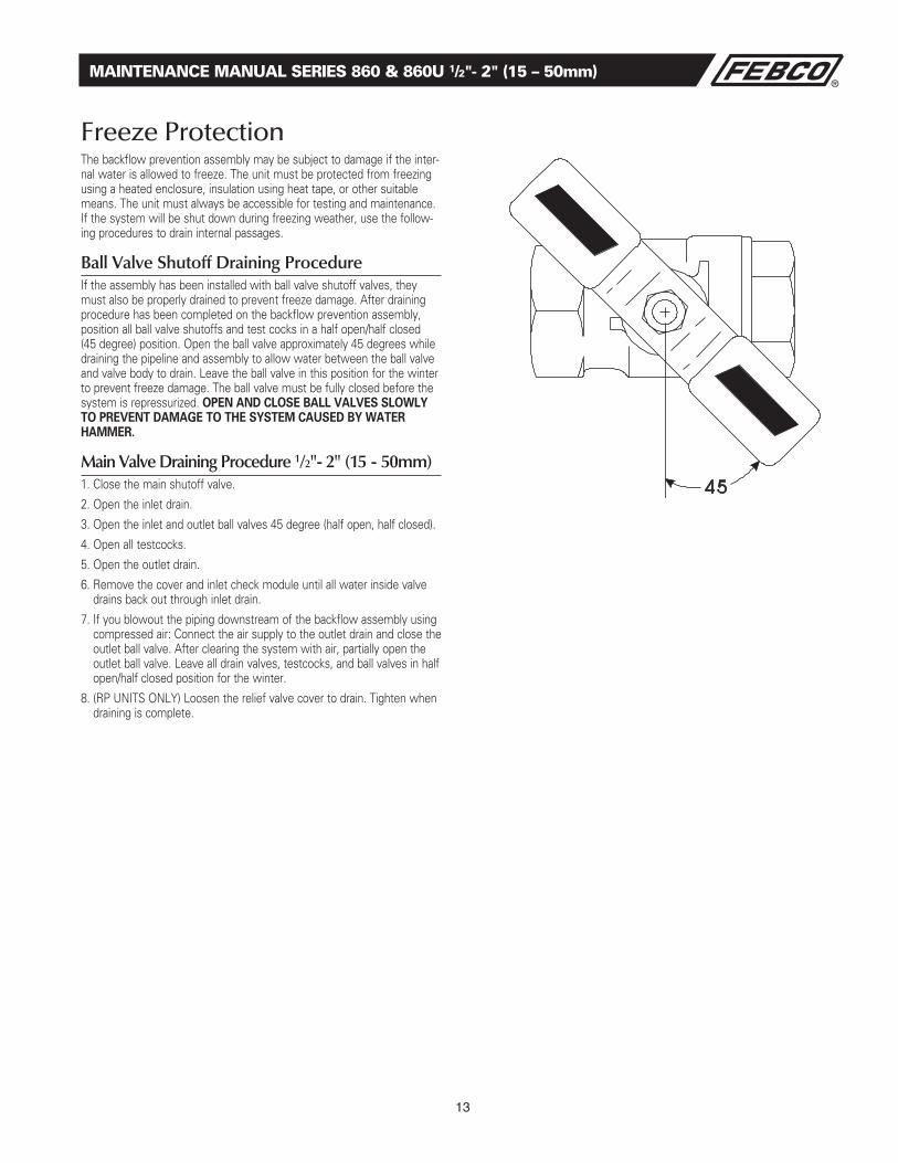
Freeze ProtectionThe backflow prevention assembly may be subject to damage if the inter-nal water is allowed to freeze . The unit must be protected from freezing using a heated enclosure, insulation using heat tape, or other suitable means . The unit must always be accessible for testing and maintenance . If the system will be shut down during freezing weather, use the follow-ing procedures to drain internal passages .
Ball Valve Shutoff Draining ProcedureIf the assembly has been installed with ball valve shutoff valves, they must also be properly drained to prevent freeze damage . After draining procedure has been completed on the backflow prevention assembly, position all ball valve shutoffs and test cocks in a half open/half closed (45 degree) position . Open the ball valve approximately 45 degrees while draining the pipeline and assembly to allow water between the ball valve and valve body to drain . Leave the ball valve in this position for the winter to prevent freeze damage . The ball valve must be fully closed before the system is repressurized . OPEN AND CLOSE BALL VALVES SLOWLY TO PREVENT DAMAGE TO THE SYSTEM CAUSED BY WATER HAMMER.
Main Valve Draining Procedure 1/2" - 2" (15 - 50mm)1 . Close the main shutoff valve .
2 . Open the inlet drain .
3 . Open the inlet and outlet ball valves 45 degree (half open, half closed) .
4 . Open all testcocks .
5 . Open the outlet drain .
6 . Remove the cover and inlet check module until all water inside valve drains back out through inlet drain .
7 . If you blowout the piping downstream of the backflow assembly using compressed air: Connect the air supply to the outlet drain and close the outlet ball valve . After clearing the system with air, partially open the outlet ball valve . Leave all drain valves, testcocks, and ball valves in half open/half closed position for the winter .
8 . (RP UNITS ONLY) Loosen the relief valve cover to drain . Tighten when draining is complete .
14
MAINTENANCE MANUAL SERIES 860 & 860U 1/2"- 2" (15 – 50mm)
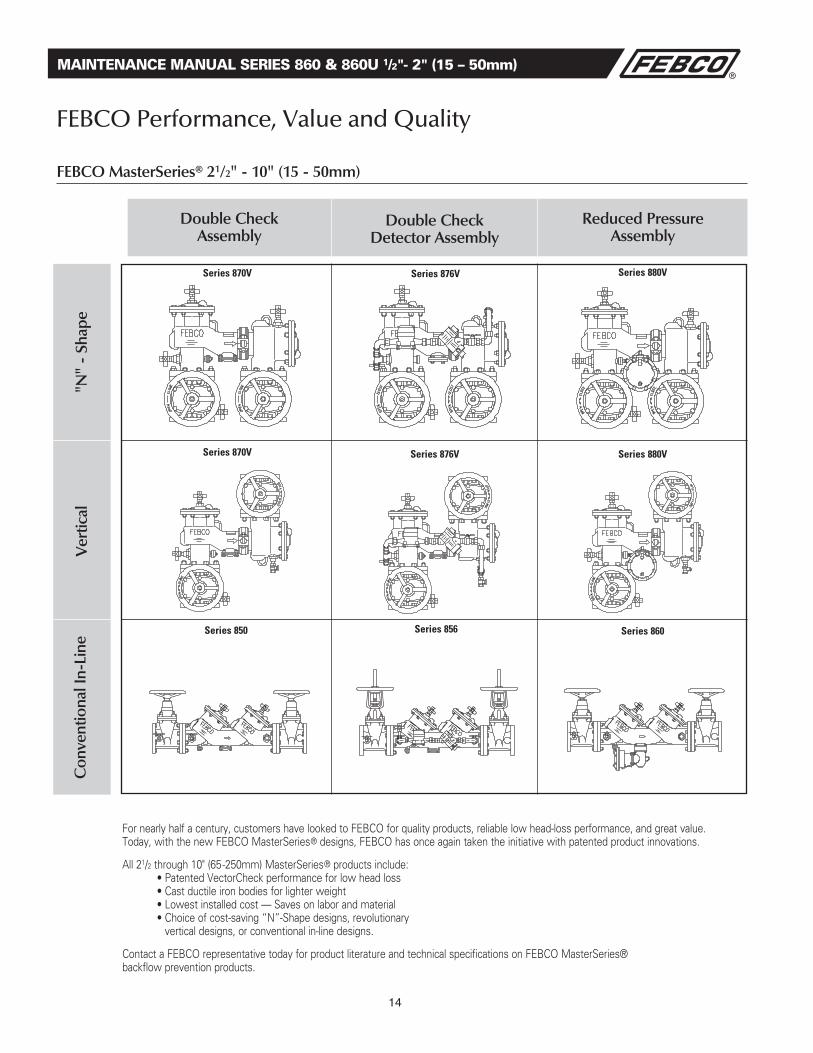
FEBCO Performance, Value and Quality
FEBCO MasterSeries® 21/2" - 10" (15 - 50mm)
For nearly half a century, customers have looked to FEBCO for quality products, reliable low head-loss performance, and great value . Today, with the new FEBCO MasterSeries® designs, FEBCO has once again taken the initiative with patented product innovations .
All 21/2 through 10" (65-250mm) MasterSeries® products include: •PatentedVectorCheckperformanceforlowheadloss •Castductileironbodiesforlighterweight •Lowestinstalledcost—Savesonlaborandmaterial •Choiceofcost-saving“N”-Shapedesigns,revolutionary
vertical designs, or conventional in-line designs .
Contact a FEBCO representative today for product literature and technical specifications on FEBCO MasterSeries® backflow prevention products .
Double Check Assembly
Double Check Detector Assembly
Reduced Pressure Assembly
Series 870V Series 876V Series 880V
Series 870V Series 876V Series 880V
Series 850 Series 856 Series 860
Con
vent
iona
l In-
Line
Ver
tical
"N"
- Sh
ape
15
MAINTENANCE MANUAL SERIES 860 & 860U 1/2"- 2" (15 – 50mm)
Notes:
For additional information, visit our web site at: www.FEBCOonline.com
A Division of Watts Water Technologies, Inc. USA: 4381 N. Brawley • Ste. 102 • Fresno, CA • 93722 • Tel. (559) 441-5300 • Fax: (559) 441-5301 • www.FEBCOonline.comCanada: 5435 North Service Rd. • Burlington, ONT. • L7L 5H7 • Tel. (905) 332-4090 • Fax: (905) 332-7068 • www.FEBCOonline.ca
IOM-F-RP 0845 EDP# 1915983 © FEBCO, 2008
Limited Warranty: FEBCO warrants each product to be free from defects in material and workmanship under normal usage for a period of one year from the date of original shipment. In the event of such defects within the warranty period, the Company will, at its option, replace or recondition the product without charge. THE WARRANTY SET FORTH HEREIN IS GIVEN EXPRESSLY AND IS THE ONLY WARRANTY GIVEN BY THE COMPANY WITH RESPECT TO THE PRODUCT. THE COMPANY MAKES NO OTHER WARRANTIES, EXPRESS OR IMPLIED. THE COMPANY HEREBY SPECIFICALLY DISCLAIMS ALL OTHER WARRANTIES, EXPRESS OR IMPLIED, INCLUDING BUT NOT LIMITED TO THE IMPLIED WARRANTIES OF MERCHANTABILITY AND FITNESS FOR A PARTICULAR PURPOSE.The remedy described in the first paragraph of this warranty shall constitute the sole and exclusive remedy for breach of warranty, and the Company shall not be responsible for any incidental, special or consequential damages, including without limitation, lost profits or the cost of repairing or replacing other property which is damaged if this product does not work properly, other costs resulting from labor charges, delays, vandalism, negligence, fouling caused by foreign material, damage from adverse water conditions, chemical, or any other circumstances over which the Company has no control. This warranty shall be invalidated by any abuse, misuse, misapplication, improper installation or improper maintenance or alteration of the product. Some States do not allow limitations on how long an implied warranty lasts, and some States do not allow the exclusion or limitation of incidental or consequential damages. Therefore the above limitations may not apply to you. This Limited Warranty gives you specific legal rights, and you may have other rights that vary from State to State. You should consult applicable state laws to determine your rights. SO FAR AS IS CONSISTENT WITH APPLICABLE STATE LAW, ANY IMPLIED WARRANTIES THAT MAY NOT BE DISCLAIMED, INCLUDING THE IMPLIED WARRANTIES OF MERCHANTABILITY AND FITNESS FOR A PARTICULAR PURPOSE, ARE LIMITED IN DURATION TO ONE YEAR FROM THE DATE OF ORIGINAL SHIPMENT.