Embed Size (px)
Citation preview
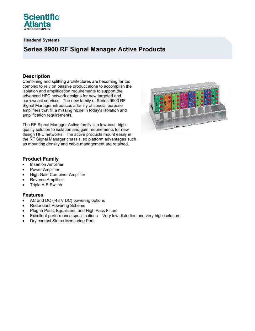
Description Combining and splitting architectures are becoming far too complex to rely on passive product alone to accomplish the isolation and amplification requirements to support the advanced HFC network designs for new targeted and narrowcast services. The new family of Series 9900 RF Signal Manager introduces a family of special purpose amplifiers that fill a missing niche in today’s isolation and amplification requirements. The RF Signal Manager Active family is a low-cost, high-quality solution to isolation and gain requirements for new design HFC networks. The active products mount easily in the RF Signal Manager chassis, so platform advantages such as mounting density and cable management are retained. Product Family • Insertion Amplifier • Power Amplifier • High Gain Combiner Amplifier • Reverse Amplifier • Triple A-B Switch Features • AC and DC (-48 V DC) powering options • Redundant Powering Scheme • Plug-in Pads, Equalizers, and High Pass Filters • Excellent performance specifications – Very low distortion and very high isolation • Dry contact Status Monitoring Port
Series 9900 RF Signal Manager Active Products Headend Systems
Series 9900 RF Signal Manager Active Products
2
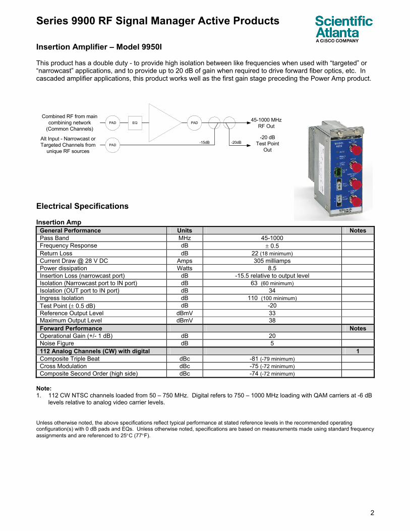
Insertion Amplifier – Model 9950I This product has a double duty - to provide high isolation between like frequencies when used with “targeted” or “narrowcast” applications, and to provide up to 20 dB of gain when required to drive forward fiber optics, etc. In cascaded amplifier applications, this product works well as the first gain stage preceding the Power Amp product.
PAD EQ PAD
PAD-15dB
Combined RF from main combining network
(Common Channels)
Alt Input - Narrowcast or Targeted Channels from
unique RF sources
45-1000 MHzRF Out
-20dB -20 dB
Test PointOut
Electrical Specifications Insertion Amp
General Performance Units Notes Pass Band MHz 45-1000 Frequency Response dB ± 0.5 Return Loss dB 22 (18 minimum) Current Draw @ 28 V DC Amps 305 milliamps Power dissipation Watts 8.5 Insertion Loss (narrowcast port) dB -15.5 relative to output level Isolation (Narrowcast port to IN port) dB 63 (60 minimum) Isolation (OUT port to IN port) dB 34 Ingress Isolation dB 110 (100 minimum) Test Point (± 0.5 dB) dB -20 Reference Output Level dBmV 33 Maximum Output Level dBmV 38 Forward Performance Notes Operational Gain (+/- 1 dB) dB 20 Noise Figure dB 5 112 Analog Channels (CW) with digital 1 Composite Triple Beat dBc -81 (-79 minimum) Cross Modulation dBc -75 (-72 minimum) Composite Second Order (high side) dBc -74 (-72 minimum)
Note: 1. 112 CW NTSC channels loaded from 50 – 750 MHz. Digital refers to 750 – 1000 MHz loading with QAM carriers at -6 dB
levels relative to analog video carrier levels. Unless otherwise noted, the above specifications reflect typical performance at stated reference levels in the recommended operating configuration(s) with 0 dB pads and EQs. Unless otherwise noted, specifications are based on measurements made using standard frequency assignments and are referenced to 25°C (77°F).
Series 9900 RF Signal Manager Active Products
3
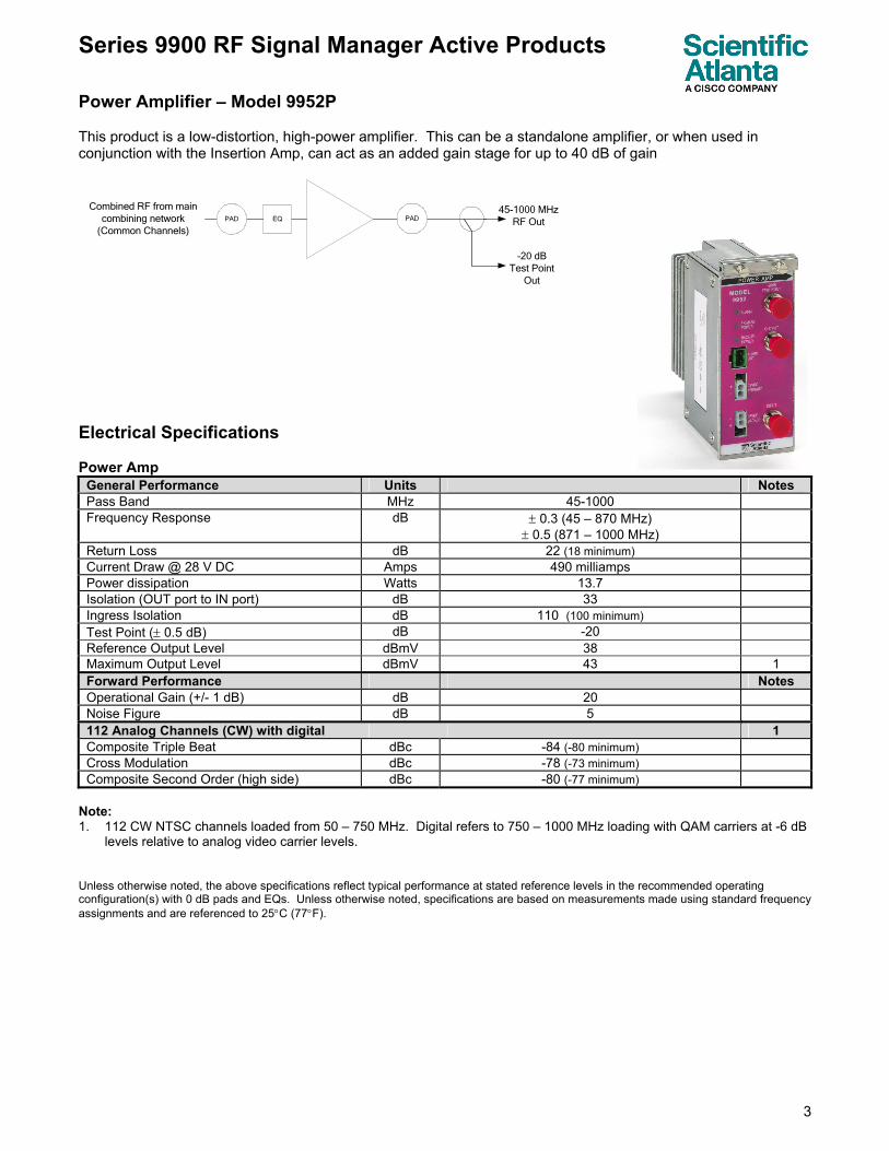
Power Amplifier – Model 9952P This product is a low-distortion, high-power amplifier. This can be a standalone amplifier, or when used in conjunction with the Insertion Amp, can act as an added gain stage for up to 40 dB of gain
PAD EQ
Combined RF from main combining network
(Common Channels)
45-1000 MHzRF Out
-20 dB Test Point
Out
PAD
Electrical Specifications Power Amp
General Performance Units Notes Pass Band MHz 45-1000 Frequency Response dB ± 0.3 (45 – 870 MHz)
± 0.5 (871 – 1000 MHz)
Return Loss dB 22 (18 minimum) Current Draw @ 28 V DC Amps 490 milliamps Power dissipation Watts 13.7 Isolation (OUT port to IN port) dB 33 Ingress Isolation dB 110 (100 minimum) Test Point (± 0.5 dB) dB -20 Reference Output Level dBmV 38 Maximum Output Level dBmV 43 1 Forward Performance Notes Operational Gain (+/- 1 dB) dB 20 Noise Figure dB 5 112 Analog Channels (CW) with digital 1 Composite Triple Beat dBc -84 (-80 minimum) Cross Modulation dBc -78 (-73 minimum) Composite Second Order (high side) dBc -80 (-77 minimum)
Note: 1. 112 CW NTSC channels loaded from 50 – 750 MHz. Digital refers to 750 – 1000 MHz loading with QAM carriers at -6 dB
levels relative to analog video carrier levels. Unless otherwise noted, the above specifications reflect typical performance at stated reference levels in the recommended operating configuration(s) with 0 dB pads and EQs. Unless otherwise noted, specifications are based on measurements made using standard frequency assignments and are referenced to 25°C (77°F).
Series 9900 RF Signal Manager Active Products
4
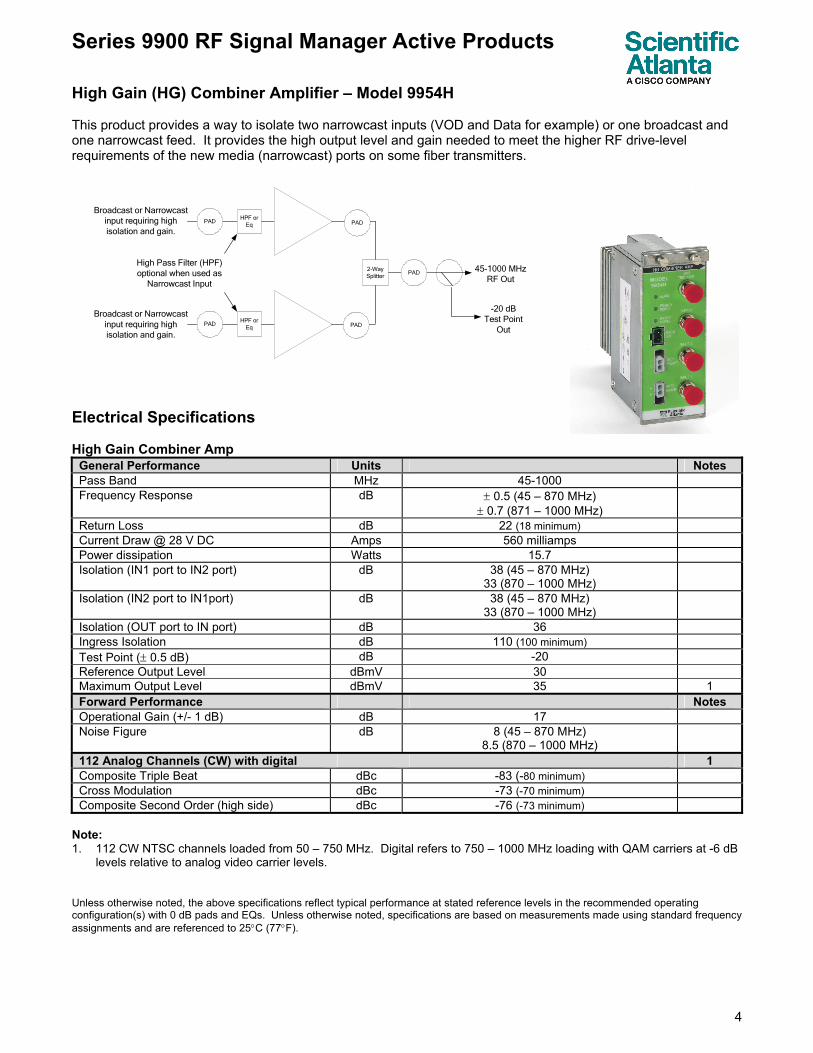
High Gain (HG) Combiner Amplifier – Model 9954H This product provides a way to isolate two narrowcast inputs (VOD and Data for example) or one broadcast and one narrowcast feed. It provides the high output level and gain needed to meet the higher RF drive-level requirements of the new media (narrowcast) ports on some fiber transmitters. Electrical Specifications High Gain Combiner Amp
General Performance Units Notes Pass Band MHz 45-1000 Frequency Response dB ± 0.5 (45 – 870 MHz)
± 0.7 (871 – 1000 MHz)
Return Loss dB 22 (18 minimum) Current Draw @ 28 V DC Amps 560 milliamps Power dissipation Watts 15.7 Isolation (IN1 port to IN2 port) dB 38 (45 – 870 MHz)
33 (870 – 1000 MHz)
Isolation (IN2 port to IN1port) dB 38 (45 – 870 MHz) 33 (870 – 1000 MHz)
Isolation (OUT port to IN port) dB 36 Ingress Isolation dB 110 (100 minimum) Test Point (± 0.5 dB) dB -20 Reference Output Level dBmV 30 Maximum Output Level dBmV 35 1 Forward Performance Notes Operational Gain (+/- 1 dB) dB 17 Noise Figure dB 8 (45 – 870 MHz)
8.5 (870 – 1000 MHz)
112 Analog Channels (CW) with digital 1 Composite Triple Beat dBc -83 (-80 minimum) Cross Modulation dBc -73 (-70 minimum) Composite Second Order (high side) dBc -76 (-73 minimum)
Note: 1. 112 CW NTSC channels loaded from 50 – 750 MHz. Digital refers to 750 – 1000 MHz loading with QAM carriers at -6 dB
levels relative to analog video carrier levels. Unless otherwise noted, the above specifications reflect typical performance at stated reference levels in the recommended operating configuration(s) with 0 dB pads and EQs. Unless otherwise noted, specifications are based on measurements made using standard frequency assignments and are referenced to 25°C (77°F).
PADHPF or
Eq
2-WaySplitter
PADHPF or
Eq
PAD
Broadcast or Narrowcast input requiring high isolation and gain.
Broadcast or Narrowcast input requiring high isolation and gain.
High Pass Filter (HPF) optional when used as
Narrowcast Input
45-1000 MHzRF Out
-20 dB Test Point
Out
PAD
PAD
Series 9900 RF Signal Manager Active Products
5
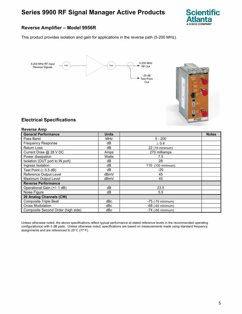
Reverse Amplifier – Model 9956R This product provides isolation and gain for applications in the reverse path (5-200 MHz). Electrical Specifications Reverse Amp
General Performance Units Notes Pass Band MHz 5 - 200 Frequency Response dB ± 0.4 Return Loss dB 22 (19 minimum) Current Draw @ 28 V DC Amps 270 milliamps Power dissipation Watts 7.5 Isolation (OUT port to IN port) dB 28 Ingress Isolation dB 110 (100 minimum) Test Point (± 0.5 dB) dB -20 Reference Output Level dBmV 45 Maximum Output Level dBmV 45 Reverse Performance Operational Gain (+/- 1 dB) dB 23.5 Noise Figure dB 5.5 26 Analog Channels (CW) Composite Triple Beat dBc -75 (-70 minimum) Cross Modulation dBc -68 (-65 minimum) Composite Second Order (high side) dBc -74 (-66 minimum)
Unless otherwise noted, the above specifications reflect typical performance at stated reference levels in the recommended operating configuration(s) with 0 dB pads. Unless otherwise noted, specifications are based on measurements made using standard frequency assignments and are referenced to 25°C (77°F).
PAD PAD5-200 MHz RF Input
Reverse Signals
5-200 MHzRF Out
-20 dB Test Point
Out
Series 9900 RF Signal Manager Active Products
6
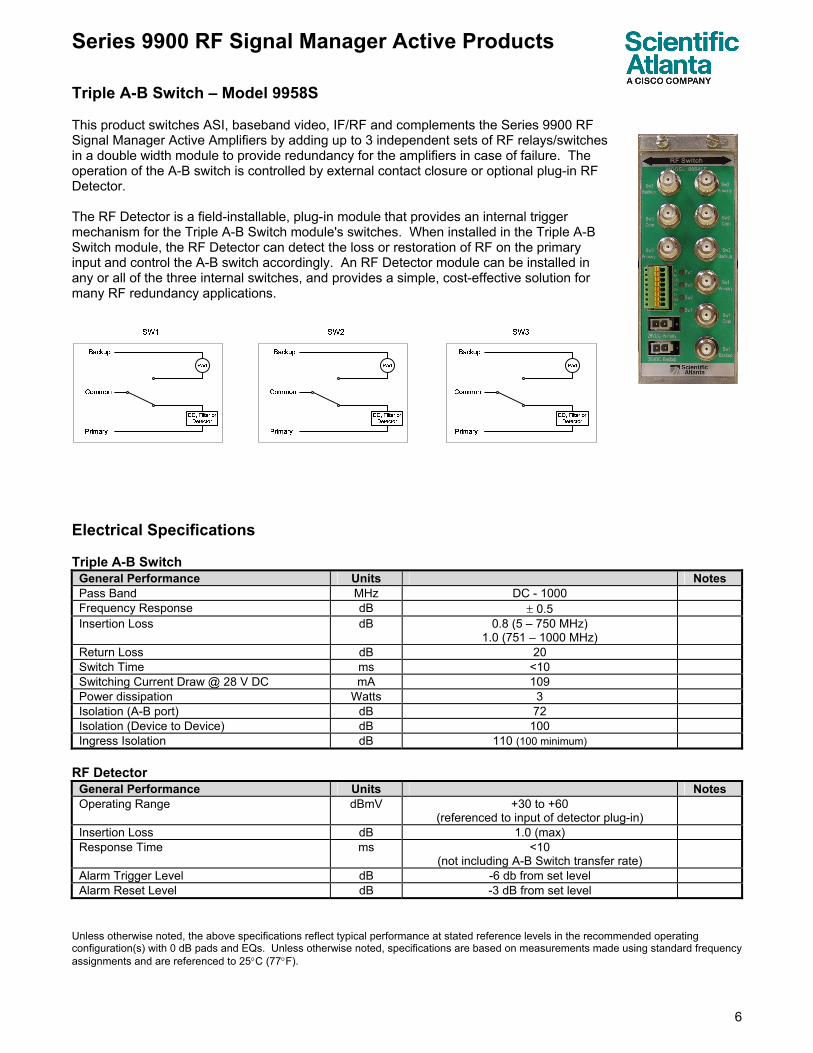
Triple A-B Switch – Model 9958S This product switches ASI, baseband video, IF/RF and complements the Series 9900 RF Signal Manager Active Amplifiers by adding up to 3 independent sets of RF relays/switches in a double width module to provide redundancy for the amplifiers in case of failure. The operation of the A-B switch is controlled by external contact closure or optional plug-in RF Detector. The RF Detector is a field-installable, plug-in module that provides an internal trigger mechanism for the Triple A-B Switch module's switches. When installed in the Triple A-B Switch module, the RF Detector can detect the loss or restoration of RF on the primary input and control the A-B switch accordingly. An RF Detector module can be installed in any or all of the three internal switches, and provides a simple, cost-effective solution for many RF redundancy applications.
Electrical Specifications Triple A-B Switch
General Performance Units Notes Pass Band MHz DC - 1000 Frequency Response dB ± 0.5 Insertion Loss dB 0.8 (5 – 750 MHz)
1.0 (751 – 1000 MHz)
Return Loss dB 20 Switch Time ms <10 Switching Current Draw @ 28 V DC mA 109 Power dissipation Watts 3 Isolation (A-B port) dB 72 Isolation (Device to Device) dB 100 Ingress Isolation dB 110 (100 minimum)
RF Detector
General Performance Units Notes Operating Range dBmV +30 to +60
(referenced to input of detector plug-in)
Insertion Loss dB 1.0 (max) Response Time ms <10
(not including A-B Switch transfer rate)
Alarm Trigger Level dB -6 db from set level Alarm Reset Level dB -3 dB from set level
Unless otherwise noted, the above specifications reflect typical performance at stated reference levels in the recommended operating configuration(s) with 0 dB pads and EQs. Unless otherwise noted, specifications are based on measurements made using standard frequency assignments and are referenced to 25°C (77°F).
Series 9900 RF Signal Manager Active Products
7
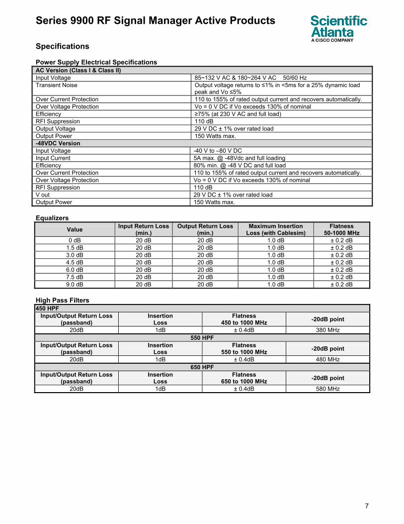
Specifications Power Supply Electrical Specifications AC Version (Class I & Class II) Input Voltage 85~132 V AC & 180~264 V AC 50/60 Hz Transient Noise Output voltage returns to ≤1% in <5ms for a 25% dynamic load
peak and Vo ≤5% Over Current Protection 110 to 155% of rated output current and recovers automatically. Over Voltage Protection Vo = 0 V DC if Vo exceeds 130% of nominal Efficiency ≥75% (at 230 V AC and full load) RFI Suppression 110 dB Output Voltage 29 V DC ± 1% over rated load Output Power 150 Watts max. -48VDC Version Input Voltage -40 V to –80 V DC Input Current 5A max. @ -48Vdc and full loading Efficiency 80% min. @ -48 V DC and full load Over Current Protection 110 to 155% of rated output current and recovers automatically. Over Voltage Protection Vo = 0 V DC if Vo exceeds 130% of nominal RFI Suppression 110 dB V out 29 V DC ± 1% over rated load Output Power 150 Watts max. Equalizers
Value Input Return Loss (min.)
Output Return Loss (min.)
Maximum Insertion Loss (with Cablesim)
Flatness 50-1000 MHz
0 dB 20 dB 20 dB 1.0 dB ± 0.2 dB 1.5 dB 20 dB 20 dB 1.0 dB ± 0.2 dB 3.0 dB 20 dB 20 dB 1.0 dB ± 0.2 dB 4.5 dB 20 dB 20 dB 1.0 dB ± 0.2 dB 6.0 dB 20 dB 20 dB 1.0 dB ± 0.2 dB 7.5 dB 20 dB 20 dB 1.0 dB ± 0.2 dB 9.0 dB 20 dB 20 dB 1.0 dB ± 0.2 dB
High Pass Filters 450 HPF
Input/Output Return Loss (passband)
Insertion Loss
Flatness 450 to 1000 MHz -20dB point
20dB 1dB ± 0.4dB 380 MHz 550 HPF
Input/Output Return Loss (passband)
Insertion Loss
Flatness 550 to 1000 MHz -20dB point
20dB 1dB ± 0.4dB 480 MHz 650 HPF
Input/Output Return Loss (passband)
Insertion Loss
Flatness 650 to 1000 MHz -20dB point
20dB 1dB ± 0.4dB 580 MHz
Series 9900 RF Signal Manager Active Products
8
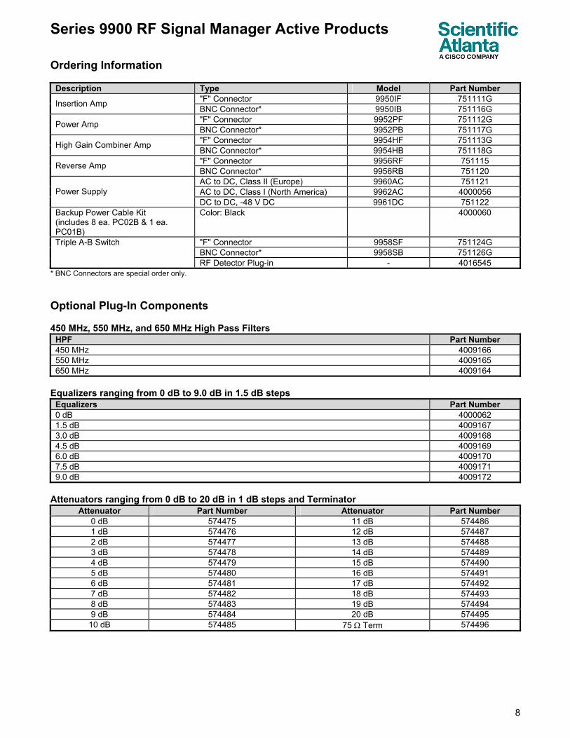
Ordering Information
Description Type Model Part Number "F" Connector 9950IF 751111G Insertion Amp BNC Connector* 9950IB 751116G "F" Connector 9952PF 751112G Power Amp BNC Connector* 9952PB 751117G "F" Connector 9954HF 751113G High Gain Combiner Amp BNC Connector* 9954HB 751118G "F" Connector 9956RF 751115 Reverse Amp BNC Connector* 9956RB 751120 AC to DC, Class II (Europe) 9960AC 751121 AC to DC, Class I (North America) 9962AC 4000056 Power Supply DC to DC, -48 V DC 9961DC 751122
Backup Power Cable Kit (includes 8 ea. PC02B & 1 ea. PC01B)
Color: Black 4000060
"F" Connector 9958SF 751124G BNC Connector* 9958SB 751126G
Triple A-B Switch
RF Detector Plug-in - 4016545 * BNC Connectors are special order only. Optional Plug-In Components 450 MHz, 550 MHz, and 650 MHz High Pass Filters
HPF Part Number 450 MHz 4009166 550 MHz 4009165 650 MHz 4009164
Equalizers ranging from 0 dB to 9.0 dB in 1.5 dB steps
Equalizers Part Number 0 dB 4000062 1.5 dB 4009167 3.0 dB 4009168 4.5 dB 4009169 6.0 dB 4009170 7.5 dB 4009171 9.0 dB 4009172
Attenuators ranging from 0 dB to 20 dB in 1 dB steps and Terminator
Attenuator Part Number Attenuator Part Number 0 dB 574475 11 dB 574486 1 dB 574476 12 dB 574487 2 dB 574477 13 dB 574488 3 dB 574478 14 dB 574489 4 dB 574479 15 dB 574490 5 dB 574480 16 dB 574491 6 dB 574481 17 dB 574492 7 dB 574482 18 dB 574493 8 dB 574483 19 dB 574494 9 dB 574484 20 dB 574495 10 dB 574485 75 Ω Term 574496
Series 9900 RF Signal Manager Active Products
9
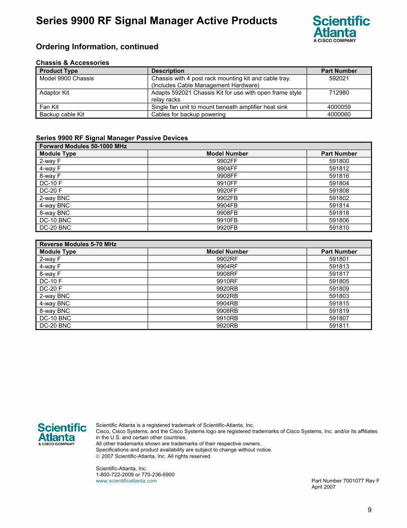
Ordering Information, continued Chassis & Accessories
Product Type Description Part Number Model 9900 Chassis Chassis with 4 post rack mounting kit and cable tray.
(Includes Cable Management Hardware) 592021
Adaptor Kit Adapts 592021 Chassis Kit for use with open frame style relay racks
712980
Fan Kit Single fan unit to mount beneath amplifier heat sink 4000059 Backup cable Kit Cables for backup powering 4000060
Series 9900 RF Signal Manager Passive Devices
Forward Modules 50-1000 MHz Module Type Model Number Part Number 2-way F 9902FF 591800 4-way F 9904FF 591812 8-way F 9908FF 591816 DC-10 F 9910FF 591804 DC-20 F 9920FF 591808 2-way BNC 9902FB 591802 4-way BNC 9904FB 591814 8-way BNC 9908FB 591818 DC-10 BNC 9910FB 591806 DC-20 BNC 9920FB 591810
Reverse Modules 5-70 MHz Module Type Model Number Part Number 2-way F 9902RF 591801 4-way F 9904RF 591813 8-way F 9908RF 591817 DC-10 F 9910RF 591805 DC-20 F 9920RB 591809 2-way BNC 9902RB 591803 4-way BNC 9904RB 591815 8-way BNC 9908RB 591819 DC-10 BNC 9910RB 591807 DC-20 BNC 9920RB 591811
Scientific Atlanta is a registered trademark of Scientific-Atlanta, Inc. Cisco, Cisco Systems, and the Cisco Systems logo are registered trademarks of Cisco Systems, Inc. and/or its affiliates in the U.S. and certain other countries. All other trademarks shown are trademarks of their respective owners. Specifications and product availability are subject to change without notice. © 2007 Scientific-Atlanta, Inc. All rights reserved. Scientific-Atlanta, Inc. 1-800-722-2009 or 770-236-6900 www.scientificatlanta.com Part Number 7001077 Rev F April 2007