Embed Size (px)
Citation preview
Towards Faster Computations and Accurate Execution of Real-Time Hybrid Simulation
Khalid M. Mosalam, Professor, PI of nees@berkeley
Selim Günay, Project Scientist, nees@berkeley
Structural Engineering, Mechanics, and Materials
Department of Civil and Environmental Engineering
University of California, Berkeley
SERIES Concluding Workshop – Joint with US-NEES, JRC-Ispra, May 28-30, 2013
1

SERIES Concluding Workshop – Joint with US-NEES, JRC-Ispra, May 28-30, 2013 2
National Science Foundation (NSF) & Network for Earthquake Engineering Simulation (NEES)
Acknowledgment:
California Department of Transportation (Caltrans) & Pacific Earthquake Engineering Research (PEER) Center
US Department of Energy (DOE) & California Institute for Energy and Environment (CIEE)
SERIES Concluding Workshop – Joint with US-NEES, JRC-Ispra, May 28-30, 2013
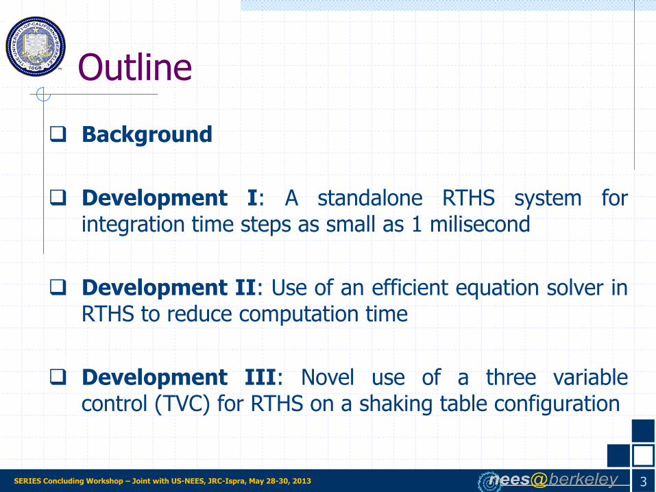
Outline
3
Background
Development I: A standalone RTHS system for integration time steps as small as 1 milisecond
Development II: Use of an efficient equation solver in RTHS to reduce computation time
Development III: Novel use of a three variable control (TVC) for RTHS on a shaking table configuration
SERIES Concluding Workshop – Joint with US-NEES, JRC-Ispra, May 28-30, 2013
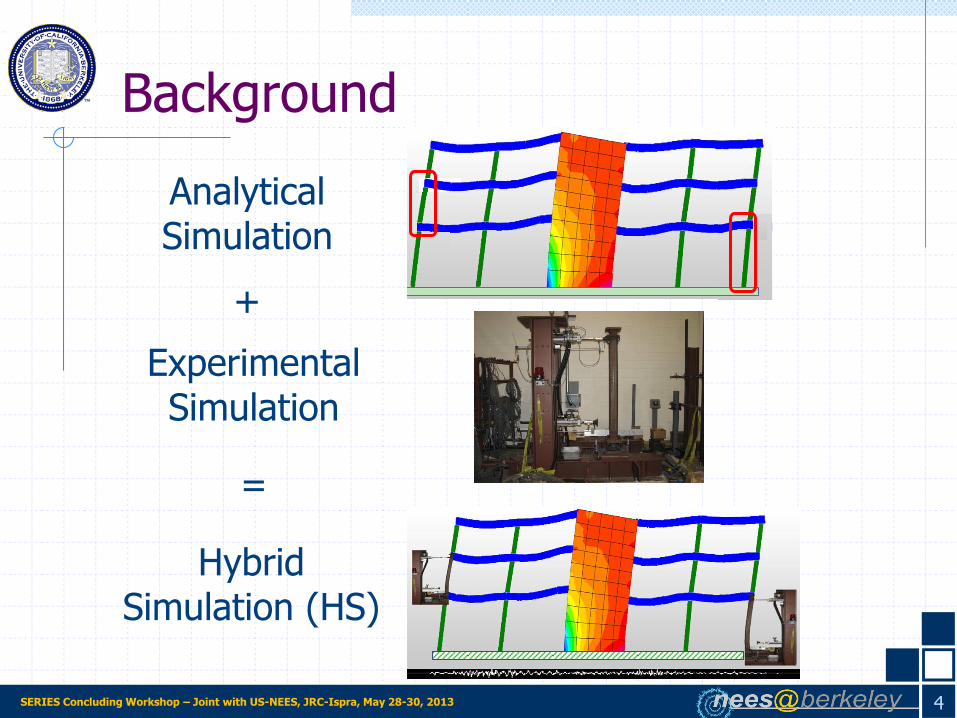
Background
Analytical Simulation
Hybrid Simulation (HS)
=
Experimental Simulation
+
4

SERIES Concluding Workshop – Joint with US-NEES, JRC-Ispra, May 28-30, 2013
Background u2
u1
m2
m1
Objective of analytical simulation: Solve the equations of motion using numerical integration methods
g
2
1
1
21
2
1
2221
1211
2
1
2
1u
m
m
u
u
cc
cc
u
u
m0
0m
f
ff
pfucum
m u c u f p
Analytical Simulation:
5

SERIES Concluding Workshop – Joint with US-NEES, JRC-Ispra, May 28-30, 2013
Background
Bottom spring replaced with a test specimen
Analytical substructure
u2
u1
m2
m1
u2
u1
m2
m1
g
2
1
2
1
2221
1211
2
1
2
1u
m
m
u
u
cc
cc
u
u
m0
0m
a
ea
f
ff
Experimental substructure
Measured
Computed
(-)
6

SERIES Concluding Workshop – Joint with US-NEES, JRC-Ispra, May 28-30, 2013
HS Classification
Background
7
HS duration = N×Δt
Real-time Hybrid Simulation
u2
u1
m2
m1
HS duration > N×Δt
Slow Hybrid Simulation
Shaking Table Configuration Actuator + Shaking Table Configuration
mkc
mkc
Bus
Experimental substructure
on a shaking table &
connected to an actuator
Actuator Configuration
u1
m, Im
u2

SERIES Concluding Workshop – Joint with US-NEES, JRC-Ispra, May 28-30, 2013
Background
Requirement for Real Time HS (RTHS):
Loading rate = Computed velocity
Slow HS is sufficient for most cases when rate effects are not important.
RTHS is essential for rate-dependent materials and devices, e.g. viscous
dampers or friction pendulum isolators.
8

SERIES Concluding Workshop – Joint with US-NEES, JRC-Ispra, May 28-30, 2013
Uniaxial shaking table
Test specimen: Insulator
Controller
DAQ & Computational platform (DSP)
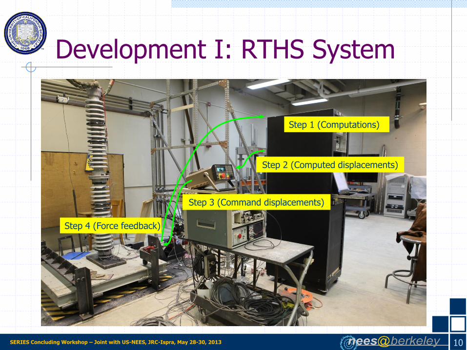
Development I: RTHS System
9
RTHS system capable of executing an integration time step of 1 millisecond
Step 1 (Computations)
Step 2 (Computed displacements)
Step 3 (Command displacements)
Step 4 (Force feedback)
SERIES Concluding Workshop – Joint with US-NEES, JRC-Ispra, May 28-30, 2013
Step 2 (Computed displacements)
Step 3 (Command displacements)
Step 4 (Force feedback)
Development I: RTHS System
10
Step 1 (Computations)
SERIES Concluding Workshop – Joint with US-NEES, JRC-Ispra, May 28-30, 2013
Development I: RTHS System
11 0 10 20 30 40 50 60 70-1.2-0.6
00.61.2
X a
cc. (g
)
19.489619.489719.489819.4899 19.49 19.490119.490219.490319.4904
0.8
1
1.2
Y a
cc. (g
)
0 10 20 30 40 50 60 70-1.2-0.6
00.61.2
Time (sec)
Z a
cc. (g
)
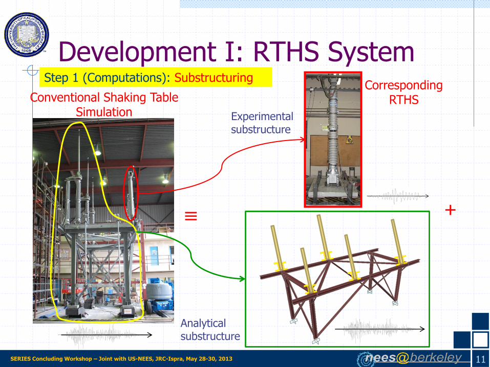
Conventional Shaking Table Simulation
≡
0 10 20 30 40 50 60 70-1.2-0.6
00.61.2
X a
cc. (g
)
19.489619.489719.489819.4899 19.49 19.490119.490219.490319.4904
0.8
1
1.2
Y a
cc. (g
)
0 10 20 30 40 50 60 70-1.2-0.6
00.61.2
Time (sec)
Z a
cc. (g
)
Analytical substructure
Step 1 (Computations): Substructuring Corresponding
RTHS
+ 0 10 20 30 40 50 60 70-10
-5
0
5
10
Dis
pla
cem
ent (in)
550 kV Switch Test
0 10 20 30 40 50 60 70-100
-50
0
50
100
Velo
city
(in
/sec)
0 10 20 30 40 50 60 70-4
-2
0
2
4
Time (sec)
Accele
ratio
n (
in/s
ec2)
Experimental substructure
SERIES Concluding Workshop – Joint with US-NEES, JRC-Ispra, May 28-30, 2013
m
k c gu
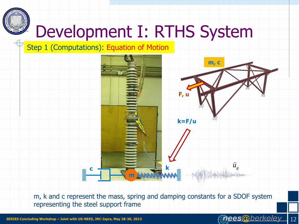
k=F/u
F, u
m, c
m, k and c represent the mass, spring and damping constants for a SDOF system representing the steel support frame
Development I: RTHS System
12
Step 1 (Computations): Equation of Motion

SERIES Concluding Workshop – Joint with US-NEES, JRC-Ispra, May 28-30, 2013
m k c guf
gumfkucvma
Force f includes the inertial and damping forces acting on the insulator since the
hybrid simulation is conducted in real time.
Development I: RTHS System
13
Step 1 (Computations): Equation of Motion

SERIES Concluding Workshop – Joint with US-NEES, JRC-Ispra, May 28-30, 2013
1 Step toGo 8)
1iiSet 7)
uγΔtuu 6)
mmpu 5)
ucfukump 4)
f Measure & u Apply 3)
u2ΔtuΔtuu 2)
uγ1Δtuu 1)
1i c,γΔtmm,u,u,u Initialize
iii
tableeffeffi
iiigeff
ii
1-i2
1-i1-ii
1-i1-ii
eff000
~
~
~
14
Development I: RTHS System Step 1 (Computations): Computational Algorithm of Explicit Newmark
Step 2 (Computed displacements)
Step 3 (Command displacements)
Step 4 (Force feedback)
Step 1 (Computations)

SERIES Concluding Workshop – Joint with US-NEES, JRC-Ispra, May 28-30, 2013
Digital signal processor (DSP) I/O module of Pacific Instruments (PI) DAQ system Programming in Reverse Polish Notation (RPN)
15
Development I: RTHS System Step 1 (Computations): Implementation of Computational Algorithm

SERIES Concluding Workshop – Joint with US-NEES, JRC-Ispra, May 28-30, 2013
10 10.2 10.4 10.6 10.8 11-1.2
-1
-0.8
-0.6
-0.4
-0.2
0
0.2
0.4
0.6
0.8
1
1.2
Time(sec)
Dis
pla
ce
me
nt(
inch
)
Command
Feedback
-40 -30 -20 -10 0 10 20 30 40-1
-0.8
-0.6
-0.4
-0.2
0
0.2
0.4
0.6
0.8
1
Velocity (v) [inch/sec]
Err
or
(e)
[inch]
e = 0.042v+0.513
e = 0.0174v
e=0.042v-0.513
Add the error to the computed displacement
16
Development I: RTHS System Step 1 (Computations): Feed-forward error compensation

SERIES Concluding Workshop – Joint with US-NEES, JRC-Ispra, May 28-30, 2013
10 10.2 10.4 10.6 10.8 11-1.2
-1
-0.8
-0.6
-0.4
-0.2
0
0.2
0.4
0.6
0.8
1
1.2
Time(sec)
Dis
pla
ce
me
nt(
inch
)
Command
Feedback
No correction
Feed-forward error correction
10 10.2 10.4 10.6 10.8 11
-1
-0.8
-0.6
-0.4
-0.2
0
0.2
0.4
0.6
0.8
1
Time(sec)
Dis
pla
ce
me
nt(
inch
)
Command
Feedback
17
Development I: RTHS System
-40 -30 -20 -10 0 10 20 30 40-1
-0.8
-0.6
-0.4
-0.2
0
0.2
0.4
0.6
0.8
1
Velocity (v) [inch/sec]
Err
or
(e)
[inch]
e = 0.042v+0.513
e = 0.0174v
e=0.042v-0.513
V=0.0 Correction=0.0
Step 1 (Computations): Feed-forward error compensation

SERIES Concluding Workshop – Joint with US-NEES, JRC-Ispra, May 28-30, 2013
Step 3 (Command displacements)
Step 4 (Force feedback)
Step 1 (Computations)
Development I: RTHS System
18
Step 2 (Computed displacements)
SERIES Concluding Workshop – Joint with US-NEES, JRC-Ispra, May 28-30, 2013
Development I: RTHS System
19
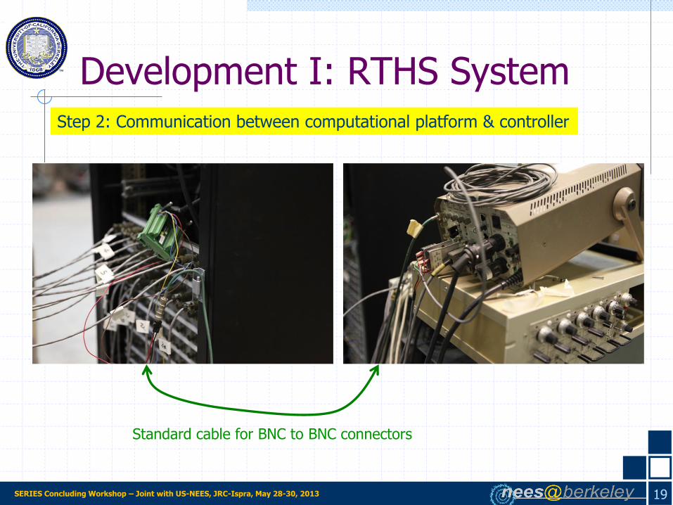
Step 2: Communication between computational platform & controller
Standard cable for BNC to BNC connectors

SERIES Concluding Workshop – Joint with US-NEES, JRC-Ispra, May 28-30, 2013
Step 1 (Computations)
Step 2 (Computed displacements)
Development I: RTHS System
20
Step 4 (Force feedback)
Step 3 (Command displacements)

SERIES Concluding Workshop – Joint with US-NEES, JRC-Ispra, May 28-30, 2013
Development I: RTHS System
21
Benefits of 1 milisecond integration capability:
Increase of the application range of Explicit integration
πT
Δt
n
milisec 1 Δt nTmilisec32.0

SERIES Concluding Workshop – Joint with US-NEES, JRC-Ispra, May 28-30, 2013
Development I: RTHS System
22
Benefits of 1 milisecond integration capability:
Eliminating approximation introduced by application of a predictor-corrector smoothing algorithm
Predict
Correct
Displacement Integration time step: 10 milisecond
ti ti+1
5 milisec 5 milisec
Integration time step: 1
milisecond
Time

SERIES Concluding Workshop – Joint with US-NEES, JRC-Ispra, May 28-30, 2013
Comparison with conventional shaking table tests
Courtesy of
Southern States
Conventional shaking table test (PEER, 2008) RTHS (UC Berkeley, 2011)
23
Development I: RTHS System
SERIES Concluding Workshop – Joint with US-NEES, JRC-Ispra, May 28-30, 2013
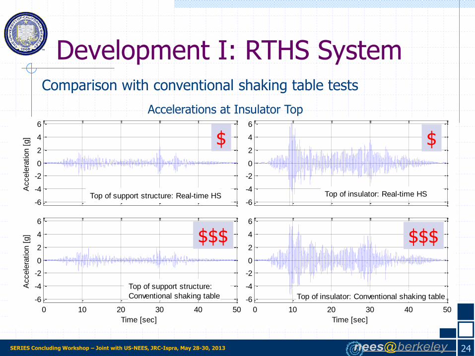
Comparison with conventional shaking table tests
Accelerations at Insulator Top
0 10 20 30 40 50
-6
-4
-2
0
2
4
6
Time [sec]
Accele
ration [
g]
-6
-4
-2
0
2
4
6
Accele
ration [
g]
0 10 20 30 40 50
-6
-4
-2
0
2
4
6
Time [sec]
-6
-4
-2
0
2
4
6
Top of support structure: Real-time HS
Top of support structure:
Conventional shaking table
Top of insulator: Real-time HS
Top of insulator: Conventional shaking table
24
Development I: RTHS System
$$$
$
$$$
$
SERIES Concluding Workshop – Joint with US-NEES, JRC-Ispra, May 28-30, 2013
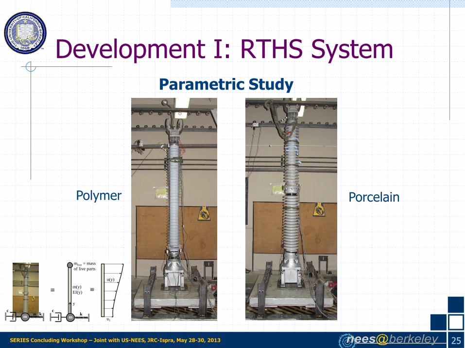
Parametric Study
Polymer Porcelain
25
Development I: RTHS System
kc
m
≡
kc
m
m(y)
EI(y)
u(y)
u1
≡
mlive = mass
of live parts
y
SERIES Concluding Workshop – Joint with US-NEES, JRC-Ispra, May 28-30, 2013
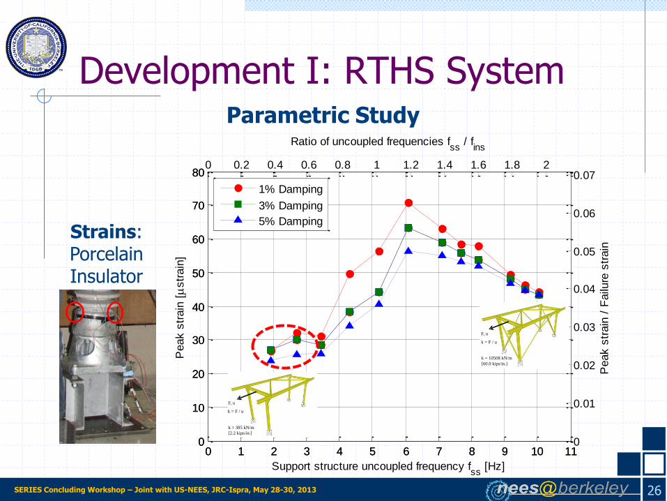
Strains: Porcelain Insulator
0 1 2 3 4 5 6 7 8 9 10 110
10
20
30
40
50
60
70
80
Support structure uncoupled frequency fss
[Hz]
Peak s
train
[
str
ain
]
0 0.2 0.4 0.6 0.8 1 1.2 1.4 1.6 1.8 2
0
10
20
30
40
50
60
70
80
Ratio of uncoupled frequencies fss
/ fins
0 1 2 3 4 5 6 7 8 9 10 110
0.01
0.02
0.03
0.04
0.05
0.06
0.07
Peak s
train
/ F
ailu
re s
train
1% Damping
3% Damping
5% Damping
26
Development I: RTHS System Parametric Study
F, u
k = F / u
k = 10508 kN/m
[60.0 kips/in.]
F, u
k = 385 kN/m
[2.2 kips/in.]
k = F / u

SERIES Concluding Workshop – Joint with US-NEES, JRC-Ispra, May 28-30, 2013
Displacements: Porcelain Insulator
0 1 2 3 4 5 6 7 8 9 10 110
0.25
0.5
0.75
1
1.25
1.5
1.75
2
Analytical substructure uncoupled frequency fss
Dis
pla
cem
ent
[in.]
0 0.2 0.4 0.6 0.8 1 1.2 1.4 1.6 1.8 2
0
0.25
0.5
0.75
1
1.25
1.5
1.75
2
Ratio of uncoupled frequencies fss
/ fins
1% damping
3% damping
5% damping
Relative displacement of
insulator w.r.t. ground
27
Parametric Study
Development I: RTHS System
F, u
k = F / u
k = 10508 kN/m
[60.0 kips/in.]
F, u
k = 385 kN/m
[2.2 kips/in.]
k = F / u

SERIES Concluding Workshop – Joint with US-NEES, JRC-Ispra, May 28-30, 2013 28
Development II: Efficient Equation Solver
Computational Platform Options for RTHS
I. Individual Platforms, e.g. programming in RPN on the DSP card, as in Development I
II. Simulink
III. Publicly available computational platforms, e.g. OpenSees
Options I and II:
Faster computation capabilities
Not versatile, case-specific, and problematic for novel users
Option III, OpenSees:
Slower than Options I & II
Well-established, versatile, research-oriented & HS compatible
Use of an efficient equation solver in OpenSees for faster computations

SERIES Concluding Workshop – Joint with US-NEES, JRC-Ispra, May 28-30, 2013 29
Development II: Efficient Equation Solver
• 3D analytical substructure
• Straightforward OpenSees model
• 12 DOF per element
• Increased matrix bandwidth
• Increased duration of coefficient matrix (keff) factorization
•
eff1 pukeff i
• Problems with real-time execution
An efficient linear solver in OpenSees: “system UmfPack –factorOnce”
Factorization of Jacobian only once at the beginning of the simulation

SERIES Concluding Workshop – Joint with US-NEES, JRC-Ispra, May 28-30, 2013 30
Development II: Efficient Equation Solver
Complements HS-compatible integrators (including nonlinear substructures): 1) Explicit & 2) Operator Splitting
Explicit Newmark Integration
1) Compute the displacements
iiii
tt uuuu
2
2
1
eff1 pumeff i
2) Compute/measure the restoring force corresponding to
3) Compute the accelerations
4) Compute the velocities 11 1 iiii γγt uuuu
uucfpucm iiiii γtγt 1111
5) Increment i
f 1i 1iu
Constant during integration Factorization is sufficient in the beginning

SERIES Concluding Workshop – Joint with US-NEES, JRC-Ispra, May 28-30, 2013 31
Development II: Efficient Equation Solver
Complements HS-compatible integrators (including nonlinear substructures): 1) Explicit & 2) Operator Splitting
Operator Splitting Integration
1) Compute the predicted displacements
eff1 pumeff i
2) Compute/measure the restoring force corresponding to
3) Compute the accelerations
5) Compute the velocities 11 1 iiii γγt uuuu
6) Increment i
ii
ttii uuuu 21
2
~2
1
1
~if 1
~iu
iiiiiI γtβtγt uucfpukcm 1~
111
2
11
2
1~
iii t uuu 4) Compute the corrected displacements
Constant during integration Factorization is sufficient in the beginning

SERIES Concluding Workshop – Joint with US-NEES, JRC-Ispra, May 28-30, 2013 32
Development II: Efficient Equation Solver
0 1000 2000 3000 4000 5000 6000 70000
10
20
30
40
# of DOF
Co
mp
uta
tio
n T
ime
pe
r T
ime
Ste
p [
ms
]
OpenSees: Multiple Factorization
OpenSees: Single Factorization
“system UmfPack –factorOnce”: Available in recent OpenSees versions

SERIES Concluding Workshop – Joint with US-NEES, JRC-Ispra, May 28-30, 2013 33
Development II: Efficient Equation Solver
N Story M bay
RTHS with 720 DOF using efficient solver
0 10 20 30 40 50 60 70 80 90 100-0.8
-0.6
-0.4
-0.2
0
0.2
0.4
0.6
0.8Force Feedback
Time [sec]
Forc
e [
kip
]
Pure Simulation
Hybrid Simulation
0 10 20 30 40 50 60 70 80 90 100-0.06
-0.04
-0.02
0
0.02
0.04
0.06Computed Acceleration (Top Node of Experimental Element)
Time [sec]
Accele
ration [
g]
Pure Simulation
Hybrid Simulation
Computed Acceleration
Experimental Element Force
-5 0 5 10
x 10-4
-20
-15
-10
-5
0
5
10
15
20
Curvature [1/inch]
Mo
me
nt
[kip
-in
ch
]
Hybrid Simulation
Pure Simulation

SERIES Concluding Workshop – Joint with US-NEES, JRC-Ispra, May 28-30, 2013
Development III: Three Variable Control (TVC) Implementation
34
Demonstration of the effect of
control-loop errors
Reliability of the HS depends on the accuracy of the force feedback
All errors that contribute to deviation of “correct” force feedback affect the HS
Command Overshoot
Measured
force
Increased
Damping
Overshooting
Displacement
Restoring
Force Restoring
Force
Displacement
Negative
Damping &
Instability
Undershooting or Delay
Displacement
Restoring
Force
SERIES Concluding Workshop – Joint with US-NEES, JRC-Ispra, May 28-30, 2013
Development III: TVC Implementation
35
How to reduce control errors?
Slow HS: Make sure that command is realized by explicit checking
RTHS:
Actuator configuration: Error compensation & tuning
Shaking table configuration: Development III

SERIES Concluding Workshop – Joint with US-NEES, JRC-Ispra, May 28-30, 2013
Development III: TVC Implementation
0 20 40 60 80 100-2
-1
0
1
2
Time (sec)
Dis
pla
cem
ent
(inches)
command
feedbackAlmost perfect displacement tracking
Acceleration mismatch at low periods
Requirement for acceleration and velocity control
0 0.5 1 1.50
0.5
1
1.5
2
Period (sec)
Sa (
g)
Target
Measured
36
Three Variable Control (TVC), developed by MTS, is a well-established displacement-velocity-acceleration control method

SERIES Concluding Workshop – Joint with US-NEES, JRC-Ispra, May 28-30, 2013
Development III: TVC Implementation
37
Dsp reference
Ref
eren
ce
gen
erat
or
Fee
db
ack
gen
erat
orDsp measurement
Acc measurement
Dsp cmd
Vel cmd
Acc cmd
Gain for Dsp cmd
Gain for Vel cmd
Gain for Acc cmd
Ʃ
Dsp fdbk
Vel fdbk
Acc fdbk
-
-
-
Gain for D error
Gain for V error
Gain for A error
Ʃ
dP measurementHigh-pass
filter
dP feedback Gain for dP
ʃ dtGain for
integrated D errorClipping
Integral
authority
Ʃ
+
+-
Notch
filters
Valve
cmd
d/dt
d/dt
Low-pass
filter
Dsp
cmd
Vel
cmd
Acc
cmd
Dsp
reference
Low-pass
filter+
ʃ ʃ dt2
d/dt
ʃ dt
d2/dt2
High-pass
filter+
+
Dsp
measurement
Acc
measurement
Dsp fdbk
Vel fdbk
Acc fdbk
Feedback generatorReference generator
Dsp: Displacement
Vel: Velocity
Acc: Acceleration
Dp: Differential pressure
cmd: Command
fdbk: Feedback
TVC Schematic as implemented in nees@berkeley

SERIES Concluding Workshop – Joint with US-NEES, JRC-Ispra, May 28-30, 2013
Three Variable Control
38
Implementation in simulink models both for Shaking Table Tests and Hybrid Simulations
Development III: TVC Implementation
Dsp reference
Ref
eren
ce
gen
erat
or
Fee
dbac
k
gen
erat
orDsp measurement
Acc measurement
Dsp cmd
Vel cmd
Acc cmd
Gain for Dsp cmd
Gain for Vel cmd
Gain for Acc cmd
Ʃ
Dsp fdbk
Vel fdbk
Acc fdbk
-
-
-
Gain for D error
Gain for V error
Gain for A error
Ʃ
dP measurementHigh-pass
filter
dP feedback Gain for dP
ʃ dtGain for
integrated D errorClipping
Integral
authority
Ʃ
+
+-
Notch
filters
Valve
cmd
d/dt
d/dt
Low-pass
filter
Dsp
cmd
Vel
cmd
Acc
cmd
Dsp
reference
Low-pass
filter+
ʃ ʃ dt2
d/dt
ʃ dt
d2/dt2
High-pass
filter+
+
Dsp
measurement
Acc
measurement
Dsp fdbk
Vel fdbk
Acc fdbk
Feedback generatorReference generator
Dsp: Displacement
Vel: Velocity
Acc: Acceleration
Dp: Differential pressure
cmd: Command
fdbk: Feedback

SERIES Concluding Workshop – Joint with US-NEES, JRC-Ispra, May 28-30, 2013
Implementation in simulink models both for Shaking Table Tests and Hybrid Simulations
39
Dsp reference
Ref
eren
ce
gen
erat
or
Fee
dbac
k
gen
erat
orDsp measurement
Acc measurement
Dsp cmd
Vel cmd
Acc cmd
Gain for Dsp cmd
Gain for Vel cmd
Gain for Acc cmd
Ʃ
Dsp fdbk
Vel fdbk
Acc fdbk
-
-
-
Gain for D error
Gain for V error
Gain for A error
Ʃ
dP measurementHigh-pass
filter
dP feedback Gain for dP
ʃ dtGain for
integrated D errorClipping
Integral
authority
Ʃ
+
+-
Notch
filters
Valve
cmd
d/dt
d/dt
Low-pass
filter
Dsp
cmd
Vel
cmd
Acc
cmd
Dsp
reference
Low-pass
filter+
ʃ ʃ dt2
d/dt
ʃ dt
d2/dt2
High-pass
filter+
+
Dsp
measurement
Acc
measurement
Dsp fdbk
Vel fdbk
Acc fdbk
Feedback generatorReference generator
Dsp: Displacement
Vel: Velocity
Acc: Acceleration
Dp: Differential pressure
cmd: Command
fdbk: Feedback
Development III: TVC Implementation
Three Variable Control

SERIES Concluding Workshop – Joint with US-NEES, JRC-Ispra, May 28-30, 2013
Enhancement of Acceleration Feedback with TVC
0 0.5 1 1.50
0.5
1
1.5
2
Period (sec)
Sa (
g)
Target
Displacement Control (STS)
40
Development III: TVC Implementation
SERIES Concluding Workshop – Joint with US-NEES, JRC-Ispra, May 28-30, 2013
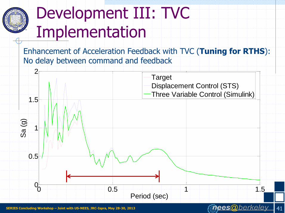
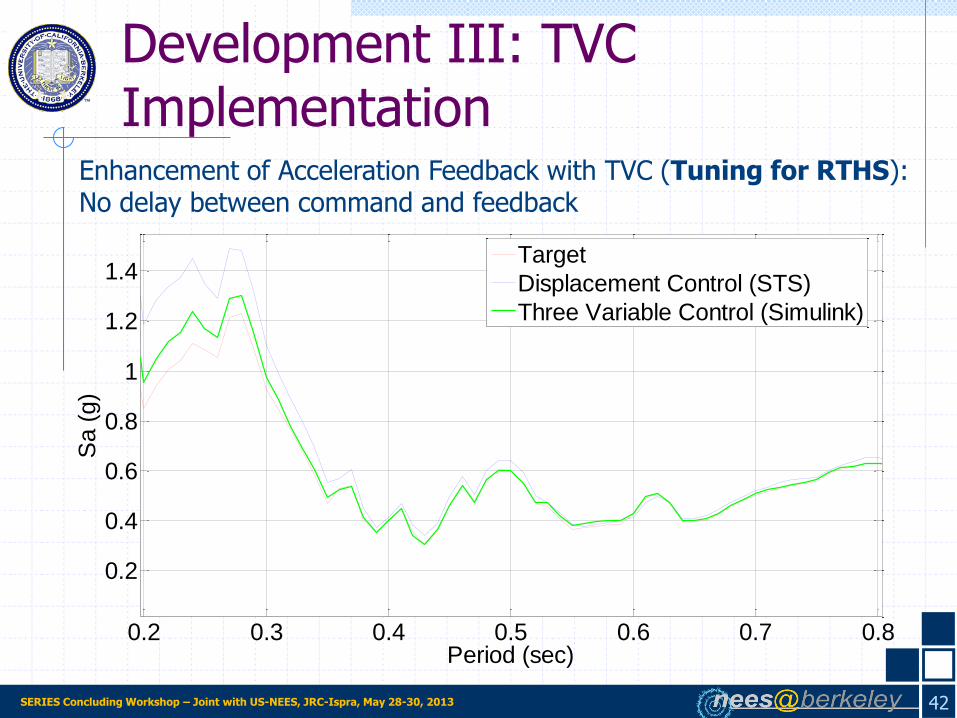
Enhancement of Acceleration Feedback with TVC (Tuning for RTHS): No delay between command and feedback
0 0.5 1 1.50
0.5
1
1.5
2
Period (sec)
Sa (
g)
Target
Displacement Control (STS)
Three Variable Control (Simulink)
41
Development III: TVC Implementation
SERIES Concluding Workshop – Joint with US-NEES, JRC-Ispra, May 28-30, 2013 42
Development III: TVC Implementation
0.2 0.3 0.4 0.5 0.6 0.7 0.8
0.2
0.4
0.6
0.8
1
1.2
1.4
Period (sec)
Sa (
g)
Target
Displacement Control (STS)
Three Variable Control (Simulink)
Enhancement of Acceleration Feedback with TVC (Tuning for RTHS): No delay between command and feedback
SERIES Concluding Workshop – Joint with US-NEES, JRC-Ispra, May 28-30, 2013
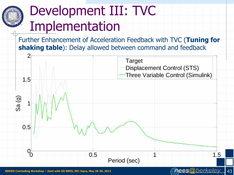
Further Enhancement of Acceleration Feedback with TVC (Tuning for shaking table): Delay allowed between command and feedback
43
Development III: TVC Implementation
0 0.5 1 1.50
0.5
1
1.5
2
Period (sec)
Sa (
g)
Target
Displacement Control (STS)
Three Variable Control (Simulink)

SERIES Concluding Workshop – Joint with US-NEES, JRC-Ispra, May 28-30, 2013
In Development I, a RTHS system is developed and can execute integration time steps of 1 milisecond.
Towards the objective of improving a general and versatile tool (OpenSees), an efficient solver is utilized in Development II to decrease computation time.
Additional challenge introduced by the control of accelerations in HS on a shaking table is addressed in the Development III by the adaptation of the three variable control for HS.
44
Recap
On-going/Future Development
Physical
Computational
SERIES Concluding Workshop – Joint with US-NEES, JRC-Ispra, May 28-30, 2013
Thank You!
Questions? Comments?
45