Embed Size (px)
Citation preview
Serpentine Coil Topology for BNL Direct Wind Superconducting Magnets
BNL-74876-2005-CP
Brett Parker and John Escallier
May 16,2005
Superconducting Magnet Division
Brookhaven National Laboratory Operated by
Brookhaven Science Associates Upton, NY 1 1973
Under Contract with the United States Department of Energy Contract Number DE-AC02-98CH10886
DlSCLAl MER
This report was prepared as an account of work sponsored by an agency of the United States Government. Neither the United States Government nor any agency thereof, nor any of their employees, nor any of their contractors, subcontractors or their employees, makes any warranty, express or implied, or assumes any legal liability or responsibility for the accuracy, completeness, or any third party's use or the results of such use of any information, apparatus, product, or process disclosed, or represents that its use would not infringe privately owned rights. Reference herein to any specific commercial product, process, or service by trade name, trademark, manufacturer, or otherwise, does not necessary constitute or imply its endorsement, recommendation, or favoring by the United States Government or any agency thereof or its contractors or subcontractors. The views and opinions of authors expresses herein do not necessarily state to reflect those of the United States Government or any agency thereof.
SERPENTINE COIL TOPOLOGY FOR BNL DIRECT WIND SUPERCONDUCTING MAGNETS*
B. Parker' and 3. Escallier, BNL, Upton, NY 11973, U.S.A.
Abstmct Serpentine winding, a recent innovation developed at
BNL for direct winding superconducting magnets, allows winding a coil layer of arbitrary multipolarity in one continuous winding process and greatly simplifies magnet design and production compared to the planar pattenis used before. Serpentine windings were used for the BEPC-I1 Upgrade and JPARC magnets and are proposed to make compact final focus magnets for the EC. Serpentine patterns exhibit a direct connection between 2D body harmonics and harmonics derived from the integral fields. Straightforward 2D optimization yields good integral field quality with uniformly spaced (natural) coil ends. This and other surprising features of Serpentine windings are addressed in this paper.
BNL DIRECT WIND HISTQRY RHIC corrector magnets were made by bonding coated
conductor in spiraling paths, here identified as "planar patterns," on flat substrate. The flat coil was wrapped around a tube for support and firmly secured in place with a tensioned Kevlar string overwrap[l]. When faced with demanding harmonic goals for the HERA-11 Upgrade, we modified this process to lay single-strand round wire and round seven-strand cable, under full computer control, directly on support tubes with substrate already attached in order to improve conductor placement accuracy[2].
But even with direct winding on support tubes, J3ERA- II patterns were fundamentally planar and suffered from limitations illustrated in Fig. 1. The spiral name of planar patterns has conductor next to the pole trapped by turns further away. This was partially mitigated by winding poles in clockwise/counterclockwise pairs but leads were still trapped and had to be bent sharply to be brought out over the final conductor pack. Leads coming from the pole interfere with later winding and are exposed and vulnerable during. subseattent txocessing. stem.
- .... .-
Figure 1. Planer Coil Schematic and HEW-II GO Quad. ~- "This manuscript has been authored by Brookhaven Science Associates. LLC under Contract No. DE-AC02-9SCH1-886 with the US. Department of Energy. The United States Government retains. and the publisher. by accepting article for publication. acknovJedges. a world- wide license to publish or reproduce published form of this manuscnpt. or aliow others to do so, for the United states Government purposes. '[email protected]
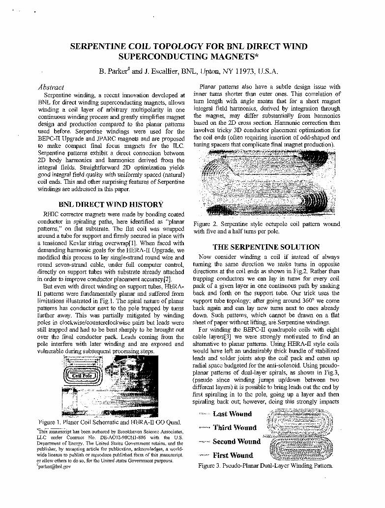
Planar patterns also have a subtle design issue with inner turns shorter than outer ones. This correlation of tun1 length with angle means that for a short magnet integral field harmonics, derived by integration through. the magnet, may differ substantially from harmonics based on the 2D cross section. Harmonic correction then involves tricky 3D conductor placement optimization for the coil ends (often requiring insertion of odd-shaped end tuning spacers that complicate final magnet production).
Figure 2. Serpentine style octupole coil pattern wound with five and a half turns per pole.
THE SERPENTINE SOLUTION Now consider winding a coil if instead of always
turning the same direction we make tuins in opposite directions at the coil ends as shown in Fig.2. Rather than trapping conductors we can lay in I m s for every coil pack of a given layer in one continuous path by snaking back and forth on the support tube. Our trick uses the support tube topology; after going around 360" we come back again and can lay new turns next to ones already down. Such patterns, which cannot be drawn on a flat sheet of paper without lifting, are Serpentine windings.
For winding the BEPC-11 quadrupole coils with eight cable layers[3] we were strongly motivated to find an alternative to planar patterns. Using €ERA-I1 style coils would have left an undesirably thick bundle of stabilized leads and solder joints atop the coil pack and eaten up radial space budgeted for the anti-solenoid. Using pseudo- planar patterns of dual-layer spirals, as shown in Fig.3, (pseudo since winding jumps upldown between two different layers) it is possible to bring leads out the end by first spiraling in to the pole, going up a layer and then spiraling back out; however, doing this strongly impacts
Figure 3. Pseudo-Planar Dual-Layer Winding Pattern.
coil production eficiency. Our standard winding process for =I mm diameter round cable uses thin GI0 cutout pieces to fill at poles and harmonic tuning spacers and alumina-filled matched expansion epoxy filling between turns and small remaining gaps. Winding two pole layers sequentially on top of each other means having to stop, fill with G10 and epoxy, cure the epoxy and then add a partial strip of fresh substrate (it cannot be spiral wound ahead of time) at each pole during coil winding.
For an eight-layer quadrupole, and especially the octupole shown in Fig.2, overhead from interrupting coil winding many times is prohibitive. Serpentine winding only stops once per layer and many of the most labor intensive steps can be done with the coil off the windmg machine freeing the machine to do other work in parallel.
We usually wind Serpentine coils in layer-pairs for the following reason. Since an N-turn Serpentine pattern snakes fully around the tube N-times, it is easy to see that a single-layer Serpentine generates not only a transverse multipole field but an N-turn solenoid. In accelerator applications when a net solenoidal field is not desirable we are carefd to wind the same number of turns, but with opposite helicity, in another layer so there is no net winding around the support tube and no extra solenoidal field. Note that 2D (ang~dar) cross sections do not need to be the same in the two layers: we only require that there be no net winding around the tube. In many situations it is desirable to use quite different patterns in each layer
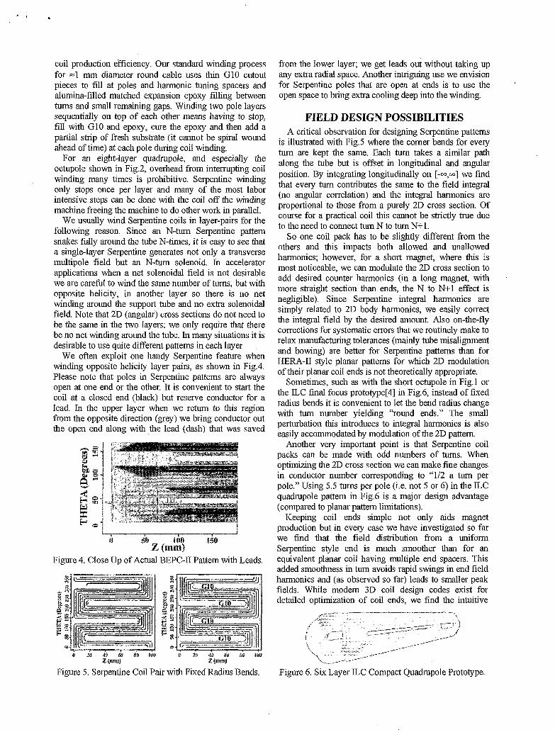
We often exploit one handy Serpentine feature when winding opposite helicity layer pairs, as shown in Fig.4. Please note that poles in Serpentine patterns are always open at one end or the other. It is convenient to start the coil at a closed end (black) but reserve conductor for a lead. In the upper layer when we return to this region from the opposite direction (grey) we bring conductor out the open end along with the lead (dash) that was saved
Figure 4. Close Up of Actual BEPC-II Pattern with Leads.
from the lower layer; we get leads out without taking up any extra radial space. Another intriguing use we envision for Serpentine poles that are open at ends is to use the open space to bring extra cooling deep into the winding.
.
FIELD DESIGN POSSIBILITIES A critical observation for designing Serpentine patterns
is illustrated with Fig.5 where the comer bends for every turn are kept the same. Each turn takes a similar path along the tube but is offset in longitudinal and angular position. By integrating longitudinally on [--,-I we find that every turn contributes the same to the field integral (no angular correlation) and the integral harmonics are proportional to those from a purely 2D cross section. O f course for a practical coil this cannot be strictly true due to the need to connect tum N to turn N+1.
So one coil pack has to be slightly different fi-om the others and this impacts both allowed and unallowed harmonics; however, for a short magnet, where this is most noticeable, we can modulate the 2D cross section to add desired counter harmonics (in a long magnet, with more straight section than ends, the N to N+1 effect is negligible). Since Serpentine integral hannonics are simply related to 2D body harmonics, we easily correct the integral field by the desired amount. Also on-the-fly corrections for systematic errors that we routinely make to relax manufacturing tolerances (mainly tube misalignment and bowing) are better for Serpentine patterns than for HEM-I1 style planar patterns for which 2D modulation of their planar coil ends is not theoretically appropriate.
Sometimes, such as with the short octupole in Fig.1 or the ILC final focus prototype[4] in Fig.6, instead of fixed radius bends it is convenient to let the bend radius change with turn number yielding “round ends.” The small perturbation this introduces to integral harmonics is also easily accommodated by modulation of the 2D pattern.
Another very important point is that Serpentine coil packs can be made with odd numbers of turns. When optimizing the 2D cross section we can make fine changes in conductor number corresponding to “112 a turn per pole.” Using 5.5 turns per pole (i.e. not 5 or 6) in the ILC quadrupole pattern in Fig.6 is a major design advantage (compared to planar pattern limitations).
Keeping coil ends simple not only aids magnet production but in every case we have investigated so far we find that the field distribution from a uniform Serpentine style end is much smoother than for an equivalent planar coil having multiple end spacers. This added smoothness in turn avoids rapid swings in end field harmonics and (as observed so far) leads to smaller peak fields. While modem 3D coil design codes exist for detailed optimization of coil ends, we find the intuitive
Figure 6. Six Layer ILC Compact Quadrupole Prototype.
simplicity of Serpentine coils and relative speed of 2D optimization to be effective for quickly generating new coil solutions to meet a variety of accelerator physics challenges (i.e. tapered-coil compensator magnets, non- symmetric combined function magnets, multiple aperture septumless magnets, super-septum magnets and more); not worrying about how to make coil ends is liberating.
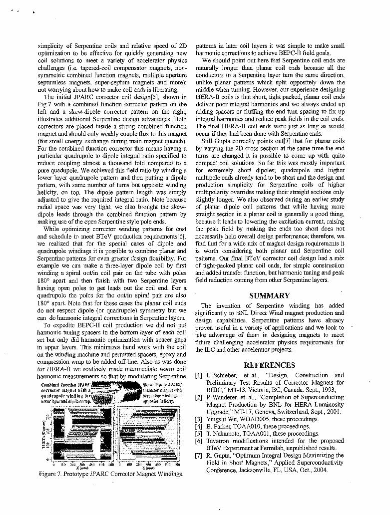
The initial JPARC corrector coil design[5], shown in Fig.7 with a combined function corrector pattern on the left and a skew-dipole corrector pattern on the right, illustrates additional Serpentine design advantages. Both correctors are placed inside a strong combined function magnet and should only weakly couple flux to this magnet (for small energy exchange during main magnet quench). For the combined function corrector this means having a particular quadrupole to dipole integral ratio specified to reduce coupling almost a thousand fold compared to a pure quadupole. We achieved this field ratio by winding a lower layer quadrupole pattern and then putting a dipole pattern, with same number of turns but opposite winding helicity, on top. The dipole pattern length was simply adjusted to give the required integral ratio. Note because radial space was very tight, we also brought the skew- dipole leads through the combined function pattern by making use of the open Serpentine style pole ends.
While optimizing corrector winding patterns for cost and schedule to meet BTeV production requirements[6], we realized that for the special cases of dipole and quadrupole windings it is possible to combine planar and Serpentine patterns for even greater design flexibility. For example we can make a three-layer dipole coil by first winding a spiral outlin coil pair on the tube with poles 180” apart and then finish with two Serpentine layers having open poles to get leads out the coil end. For a quadrupole the poles for the outlin spiral pair are also 180” apart. Note that for these cases the planar coil ends do not respect dipole (or quadrupole) symmetry but we can do harmonic integral corrections in Serpentine layers.
To expedite BEPC-I1 coil production we did not put harmonic tuning spacers in the bottom layer of each coil set but only did harmonic optimization with spacer gaps in upper layers. This minimizes hand work with the coil on the winding machine and permitted spacers, epoxy and compression wrap to be added off-line. Also as was done for HERA-I1 we routinely made interniediate warm coil harmonic measurements so that by modulating Serpentine
patterns in later coil layers it was simple to make small harmonic corrections to achieve BEPC-I1 field goals.
We should point out here that Serpentine coil ends are naturally longer than planar coil ends because all the conductors in a Serpentine layer tum the same direction, unlike planar patterns which split oppositely down the middle when tuming. However, our experience designing HEM-II coils is that short, tight packed, planar coil ends deliver poor integral harmonics and we always ended up adding spacers or fluffing the end turn spacing to fix up integral harmonics and reduce peak fields in the coil ends. The final HERA-II coil ends were just as long as would occur if they had been done with Serpentine ends.
Still Gupta correctly points out[7] that for planar coils by varying the 2D cross section at the same time the end turns are changed it is possible to come up with quite compact coil solutions. So far this was mostly important for extremely short dipoles; quadrupole and higher multipole ends already tend to be short and the design and production simplicity for Serpentine coils of higher multipolarity overrides making their straight sections only slightly longer. We also observed during an earlier study of planar dipole coil patterns that while having more straight section in a planar coil is generally a good thing, because it leads to lowering the excitation current, raising the peak field by making the ends too short does not necessarily help overall design performance; therefore, we find that for a wide mix of magnet design requirements it is worth considering both planar and Serpentine coil patterns. Our final BTeV corrector coil design had a mix of tight-packed planar coil ends, for simple construction and added transfer function, but harmonic tuning and peak field reduction coming from other Serpentine layers.
SUMMARY The invention of Seipentine winding has added
significantly to BNL Direct Wind magnet production and design capabilities. Serpentine patterns have already proven useful in a variety of applications and we look to take advantage of them in designing magnets to meet future challenging accelerator physics requirements for the ILC and other accelerator projects.
REFERENCES [I] L. Schieber, et. al., “Design, Construction and
Preliminary Test Results of Corrector Magnets for RHIC,” MT-13, Victoria, BC, Canada. Sept., 1993,
[2] P. Wanderer, et. al., “Completion of Superconducting Magnet Production by BNL for HERA Luminosity Upgrade,” MT-17, Geneva, Switzerland, Sept., 2001.
[3] Yingshi Wu, WOADOOS, these proceedings. [4] B. Parker, TOAAO10, these proceedings. [5] T. Nakamoto, TOAA001, these proceedings. [6] Tevatron modifications intended for the proposed
BTeV Experiment at Fermilab, unpublished results. [7] R. Gupt% “Optimum Integral Design Maxiinizing the
Field in Short Magnets,” Applied Superconductivity Conference, Jacksonville, FL, USA, Oct., 2004.


![Design Report BNL - E951 15T Pulsed Magnet for Mercury ... · [8] "Case Studies in Superconducting Magnets" Design and operational Issues, by Yukikazu Iwasa , Plenum Press, New York](https://img.pdfslide.net/doc/110x75/604c5a005682e707122e73d1/design-report-bnl-e951-15t-pulsed-magnet-for-mercury-8-case-studies.jpg)