Embed Size (px)
Citation preview
Service and Installation Manual
Machine parts and electrical drawings
V3.4
G2504 Girotec RDL 1800 G0804 Girotec PL 2000/PLB 2000 G1005 Girotec ST 2000/STB 2000 G1205 Girotec ST 1800 G2905 Girotec ST3 2000 G1304 Girotec WT2 2000 G1504 Girotec WT3 2000
INSTALLATION
SEM
I-A
UT
OM
ATIC
MA
CH
INES
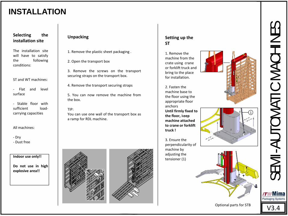
Selecting the installation site The installation site will have to satisfy the following conditions: ST and WT machines: - Flat and level surface - Stable floor with sufficient load-carrying capacities All machines: - Dry - Dust free Indoor use only!! Do not use in high explosive area!!
Unpacking 1. Remove the plastic sheet packaging . 2. Open the transport box 3. Remove the screws on the transport securing straps on the transport box. 4. Remove the transport securing straps 5. You can now remove the machine from the box. TIP: You can use one wall of the transport box as a ramp for RDL machine.
Setting up the ST 1. Remove the machine from the crate using crane or forklift truck and bring to the place for installation. 2. Fasten the machine base to the floor using the appropriate floor anchors Until firmly fixed to the floor, keep machine attached to crane or forklift truck ! 3. Ensure the perpendicularity of machine by adjusting the tensioner (1)
V3.4
1
Optional parts for STB
INSTALLATION
SEM
I-A
UT
OM
ATIC
MA
CH
INES
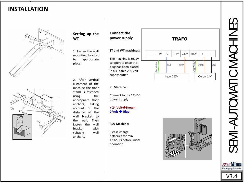
Setting up the WT 1. Fasten the wall mounting bracket to appropriate place. 2. After vertical alignment of the machine the floor stand is fastened using the appropriate floor anchors, taking account of the distance of the wall bracket to the wall. Then fasten the wall bracket with suitable wall anchors.
Connect the power supply ST and WT machines: The machine is ready to operate once the plug has been placed in a suitable 230 volt supply outlet. PL Machine: Connect to the 24VDC power supply + 24 VoltBrown 0 Volt Blue RDL Machine: Please charge batteries for min. 12 hours before initial operation.
V3.4

KEEP UP INSTRUCTION
SEM
I-A
UT
OM
ATIC
MA
CH
INES
V3.4
Weekly -Wipe off dust and dirt from the whole machine using dry cloth.
-Wipe off dust and dirt from the film distributor using dry cloth( especially from the photocell). - Wipe off dust and dirt from the film distributor roller (1) using cloth with cleaning spray
Monthly -Wipe off dust and dirt from the guiding profile (3) using cloth with cleaning spray.
-Use silicon spray to lubricate the path (3) and sliding pieces (2). -Check the brake plate has a minimum of 0,5mm of material. -Lubricate the brake system bushing. -Lubricate the lifting leverages and bushings. -Lubricate the bushings of the hydraulic system.
1
2
3
KEEP UP INSTRUCTION
SEM
I-A
UT
OM
ATIC
MA
CH
INES
V3.4
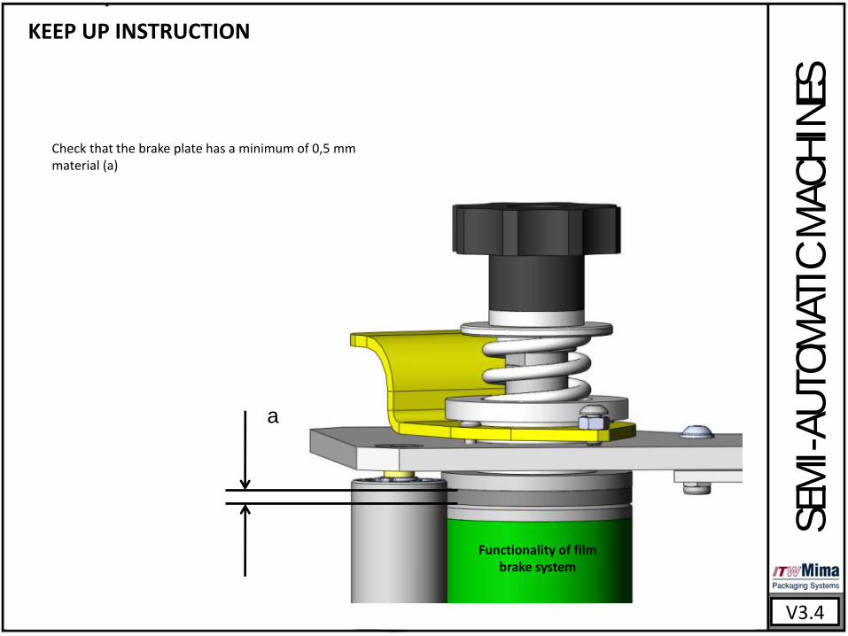
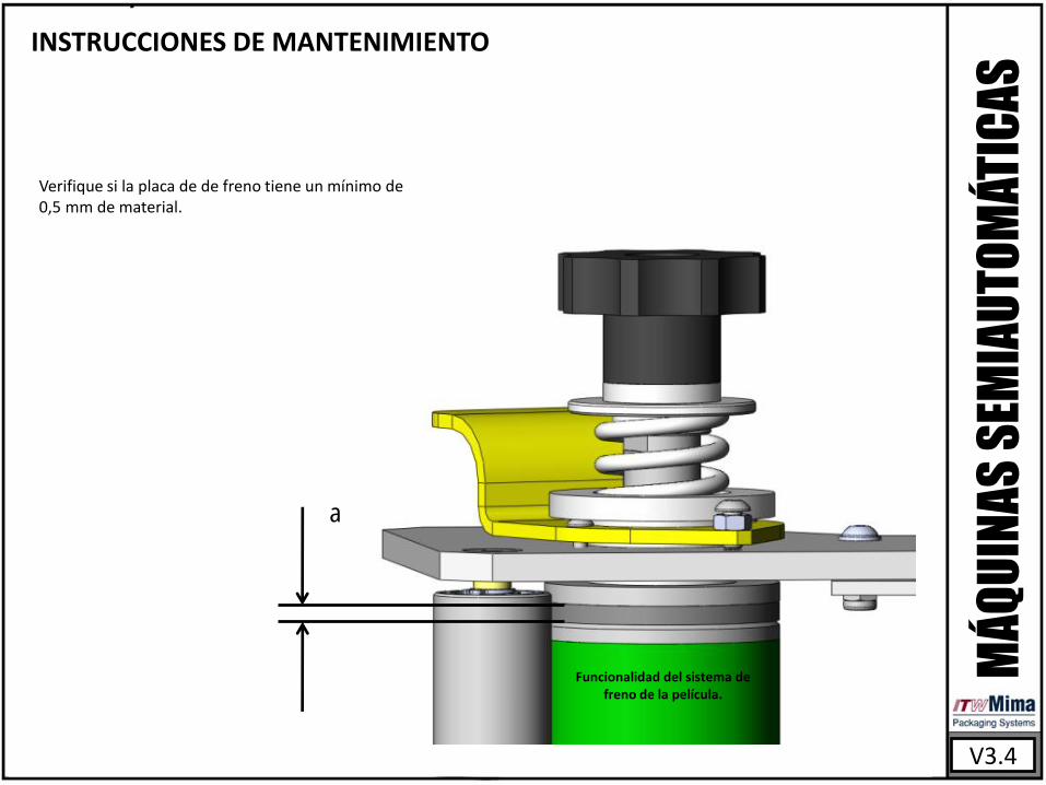
Check that the brake plate has a minimum of 0,5 mm material (a)
Functionality of film brake system
a
KEEP UP INSTRUCTION
SEM
I-A
UT
OM
ATIC
MA
CH
INES
V3.4
1
2
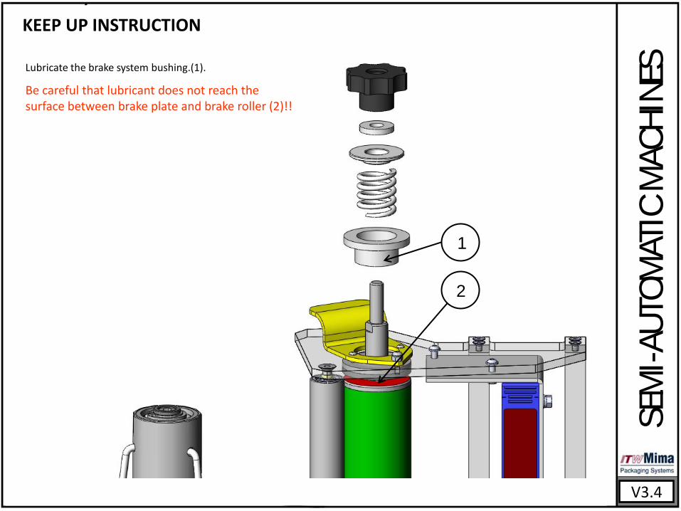
Lubricate the brake system bushing.(1).
Be careful that lubricant does not reach the surface between brake plate and brake roller (2)!!

Kundensienst- und Montageeinleitung
Maschinenteile und Strompläne
V3.4
G2504 Girotec RDL 1800 G0804 Girotec PL 2000/PLB 2000 G1005 Girotec ST 2000/STB 2000 G1205 Girotec ST 1800 G2905 Girotec ST3 2000 G1304 Girotec WT2 2000 G1504 Girotec WT3 2000

MONTAGE
V3.4
Auswahl des Montageortes Der Montageort soll folgenden Bedingungen entsprechen: Für Maschinen Stund WT: -Ebene und horizontale Oberfläche.
-Robster Boden mit ausreichend Tragfähigkeit 1.Der Platz soll trocken sein
2.Staubfrei
Nur in geschlossenen Räumen verwenden!! Nicht in Bereichen mit erhöhter Explosionsgefahr betreiben!!
Auspacken 1. Die Verpackung aus Kunstoffbogen und Festpappe entfernen. 2. Die Transportkiste öffnen. 3. Die Bänder für die Sicherung der Maschine während des Transportes von der Transportkiste lockern. 4. Die Sichrungsbänder entfernen. 5. Jetzt können Sie die Maschine aus der Kiste holen. NÜTZLICHER RAT: Sie können eine der Wänder der Maschine als Rampe für die Maschine RDL verwenden.
Installation von ST 1. Nehmen Sie die Maschine aus der Holzkiste mit der Hilfe des Krans oder Gabelstapplers heraus und bringen Sie zum Platz der Installation.
2. Befestigen Sie Grundplatte der Maschine mit Ankerbolzen zum Boden. Bis die Maschine nicht fest am Boden verankert wird, soll sie nicht vom Kran oder Gabelstappler entfernt werden!
3. Versichern Sie die Rechtwinklichkeit der Maschine durch Einstellen der Spannstange (1).
HA
LBA
UT
OM
ATIS
CH
E M
AS
CH
INEN
1
Optional parts for STB
MONTAGE
HA
LBA
UT
OM
ATIS
CH
E M
AS
CH
INEN
V3.4
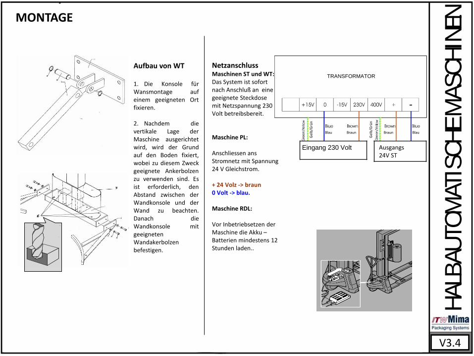
Aufbau von WT 1. Die Konsole für Wansmontage auf einem geeigneten Ort fixieren. 2. Nachdem die vertikale Lage der Maschine ausgerichtet wird, wird der Grund auf den Boden fixiert, wobei zu diesem Zweck geeignete Ankerbolzen zu verwenden sind. Es ist erforderlich, den Abstand zwischen der Wandkonsole und der Wand zu beachten. Danach die Wandkonsole mit geeigneten Wandakerbolzen befestigen.
Netzanschluss Maschinen ST und WT: Das System ist sofort nach Anschluß an eine geeignete Steckdose mit Netzspannung 230 Volt betreibsbereit. Maschine PL: Anschliessen ans Stromnetz mit Spannung 24 V Gleichstrom. + 24 Volz -> braun 0 Volt -> blau. Maschine RDL: Vor Inbetriebsetzen der Maschine die Akku – Batterien mindestens 12 Stunden laden..
Eingang 230 Volt Ausgangs 24V ST
TRANSFORMATOR
Gel
b/G
rün
Blau Braun Braun Blau
Gel
b/G
rün
WARTUNGSANWEISUNGEN
V3.4
Einmal in der Woche
Einmal im Monat
HA
LBA
UT
OM
ATIS
CH
E M
AS
CH
INEN
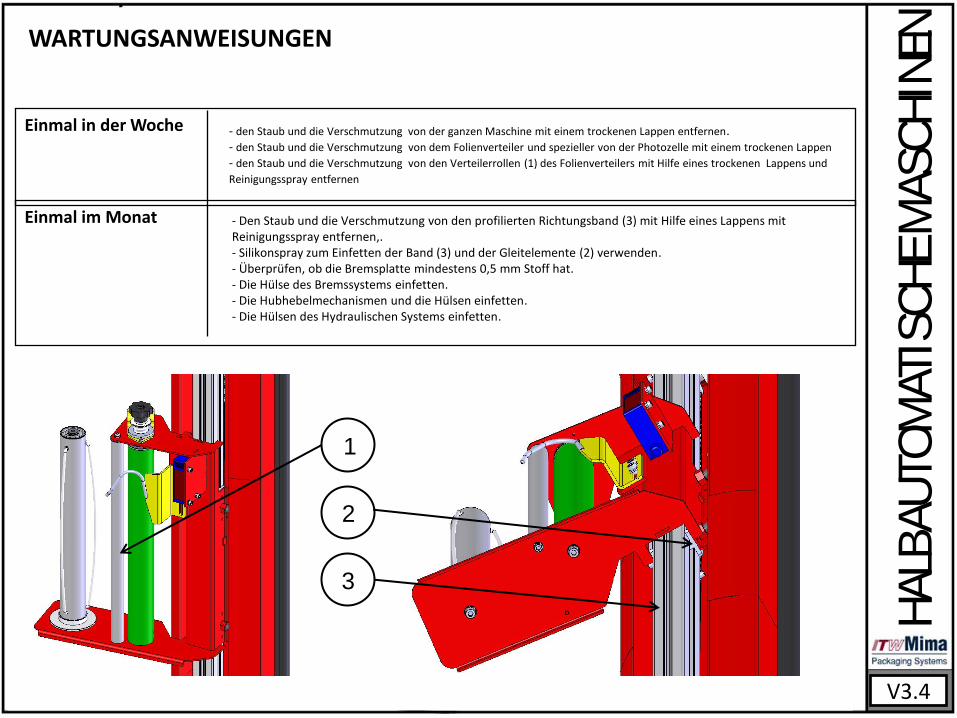
- den Staub und die Verschmutzung von der ganzen Maschine mit einem trockenen Lappen entfernen. - den Staub und die Verschmutzung von dem Folienverteiler und spezieller von der Photozelle mit einem trockenen Lappen
- den Staub und die Verschmutzung von den Verteilerrollen (1) des Folienverteilers mit Hilfe eines trockenen Lappens und
Reinigungsspray entfernen
- Den Staub und die Verschmutzung von den profilierten Richtungsband (3) mit Hilfe eines Lappens mit Reinigungsspray entfernen,. - Silikonspray zum Einfetten der Band (3) und der Gleitelemente (2) verwenden. - Überprüfen, ob die Bremsplatte mindestens 0,5 mm Stoff hat. - Die Hülse des Bremssystems einfetten. - Die Hubhebelmechanismen und die Hülsen einfetten. - Die Hülsen des Hydraulischen Systems einfetten.
1
2
3

WARTUNGSANWEISUNG
V3.4
Überprüfen, ob die Bremsplatte mindestens 0,5 mm Stoff (Stoffe) hat.
HA
LBA
UT
OM
ATIS
CH
E M
AS
CH
INEN
a
Funktionalität des Bremssystems für die
Folie.
WARTUNGSANWEISUNGEN
V3.4
HA
LBA
UT
OM
ATIS
CH
E M
AS
CH
INEN
1
2
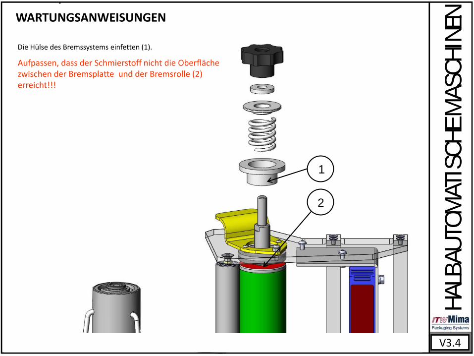
Die Hülse des Bremssystems einfetten (1).
Aufpassen, dass der Schmierstoff nicht die Oberfläche zwischen der Bremsplatte und der Bremsrolle (2) erreicht!!!

Manuel d’entretien et d’installation Composants de la machine et schémas de l’équipement électrique
V3.4
G2504 Girotec RDL 1800 G0804 Girotec PL 2000/PLB 2000 G1005 Girotec ST 2000/STB 2000 G1205 Girotec ST 1800 G2905 Girotec ST3 2000 G1304 Girotec WT2 2000 G1504 Girotec WT3 2000
INSTALLATION
MA
CH
INES
SEM
I-A
UT
OM
ATIQ
UES
V3.4
Choix d’un palier d’installation
Le palier d’installation doit correspondre aux exigences suivantes : POUR DES MACHINES ST et WT: -surface plane et horizontale.
-sol stable possédant une capacité de charge suffisante.
Pour toutes les machines: -Le palier doit être sec. -il ne doit pas y avoir de poussière.
Exploitation uniquement en lieu clos !! Ne pas utiliser dans des zones explosibles !!
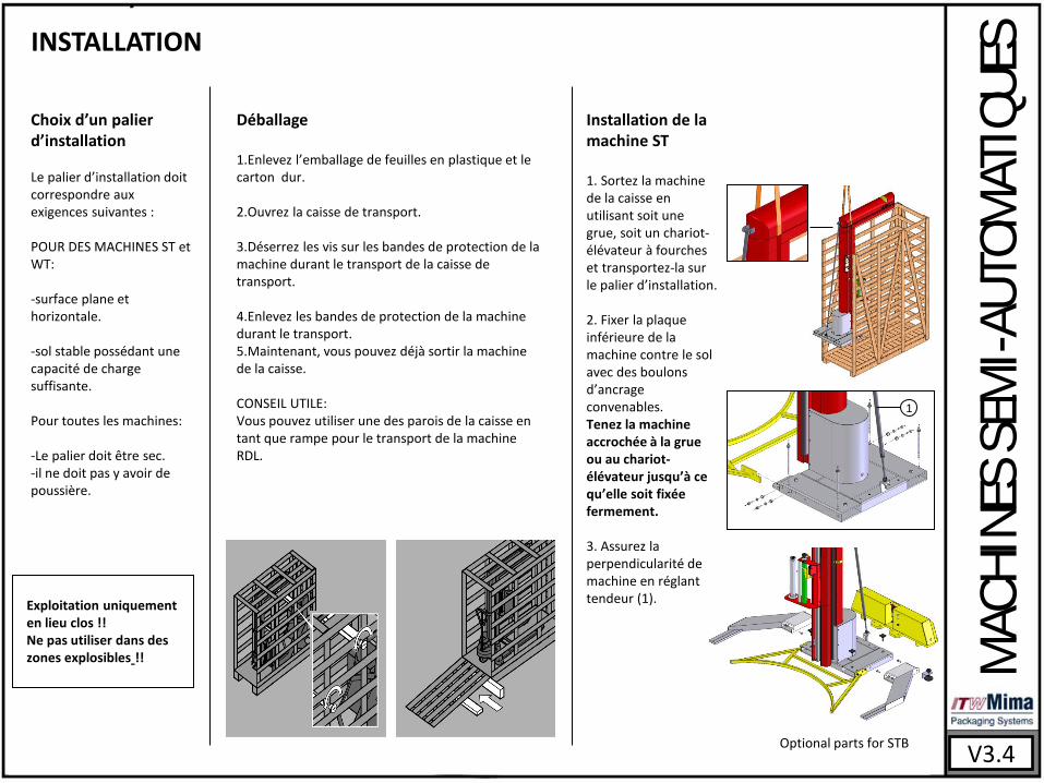
Déballage 1.Enlevez l’emballage de feuilles en plastique et le carton dur.
2.Ouvrez la caisse de transport.
3.Déserrez les vis sur les bandes de protection de la machine durant le transport de la caisse de transport.
4.Enlevez les bandes de protection de la machine durant le transport. 5.Maintenant, vous pouvez déjà sortir la machine de la caisse.
CONSEIL UTILE: Vous pouvez utiliser une des parois de la caisse en tant que rampe pour le transport de la machine RDL.
Installation de la machine ST 1. Sortez la machine de la caisse en utilisant soit une grue, soit un chariot-élévateur à fourches et transportez-la sur le palier d’installation. 2. Fixer la plaque inférieure de la machine contre le sol avec des boulons d’ancrage convenables. Tenez la machine accrochée à la grue ou au chariot-élévateur jusqu’à ce qu’elle soit fixéе fermement. 3. Assurez la perpendicularité de la machine en réglant le tendeur (1).
1
Optional parts for STB
INSTALLATION
V3.4
MA
CH
INES
SEM
I-A
UT
OM
ATIQ
UES
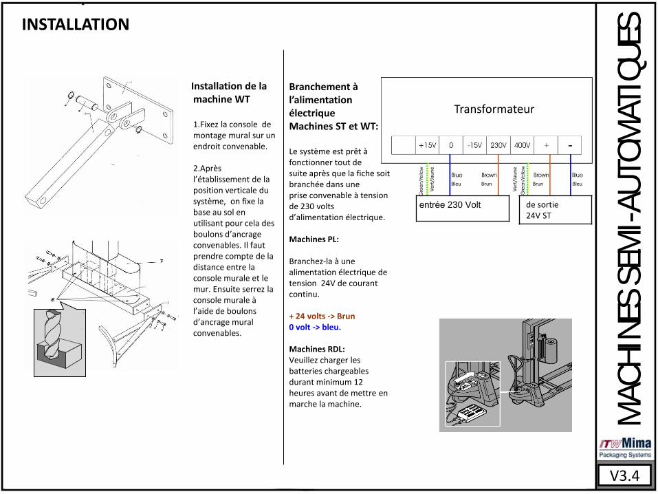
Installation de la machine WT
1.Fixez la console de
montage mural sur un endroit convenable.
2.Après l’établissement de la position verticale du système, on fixe la base au sol en utilisant pour cela des boulons d’ancrage convenables. Il faut prendre compte de la distance entre la console murale et le mur. Ensuite serrez la console murale à l’aide de boulons d’ancrage mural convenables.
entrée 230 Volt de sortie 24V ST
Transformateur
Ver
t/Ja
un
e
Bleu Brun Brun Bleu
Ver
t/Ja
un
e
Branchement à l’alimentation électrique Machines ST et WT: Le système est prêt à fonctionner tout de suite après que la fiche soit branchée dans une prise convenable à tension de 230 volts d’alimentation électrique. Machines PL: Branchez-la à une alimentation électrique de tension 24V de courant continu. + 24 volts -> Brun 0 volt -> bleu. Machines RDL: Veuillez charger les batteries chargeables durant minimum 12 heures avant de mettre en marche la machine.
CONSIGNES D’ENTRETIEN
V3.4
Une fois par semaine
Une fois par mois
MA
CH
INES
SEM
I-A
UT
OM
ATIQ
UES
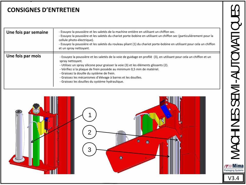
- Essuyez la poussière et les saletés de la machine entière en utilisant un chiffon sec. - Essuyez la poussière et les saletés du chariot porte-bobine en utilisant un chiffon sec (particulièrement pour la cellule photo-électrique). - Essuyez la poussière et les saletés du rouleau pliant (1) du chariot porte-bobine en utilisant pour cela un chiffon et un spray nettoyant.
- Essuyez la poussière et les saletés de la voie de guidage en profilé (3), en utilisant pour cela un chiffon et un spray nettoyant. - Utilisez un spray silicone pour graisser la voie (3) et les éléments glissants (2). - Vérifiez si la plaque de frein possède au minimum 0,5 mm de matériel. - Graissez la douille du système de frein. - Graissez les mécanismes d’élévage à barres et les douilles. - Graissez les douilles du système hydraulique.
1
2
3
V3.4
MA
CH
INES
SEM
I-A
UT
OM
ATIQ
UES
CONSIGNES D’ENTRETIEN
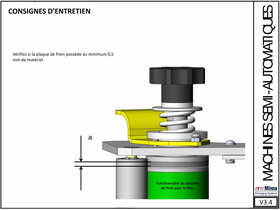
Vérifiez si la plaque de frein possède au minimum 0,5 mm de matériel.
a
Fonctionnalité du système de frein pour le film.
V3.4
MA
CH
INES
SEM
I-A
UT
OM
ATIQ
UES
CONSIGNES D’ENTRETIEN
1
2
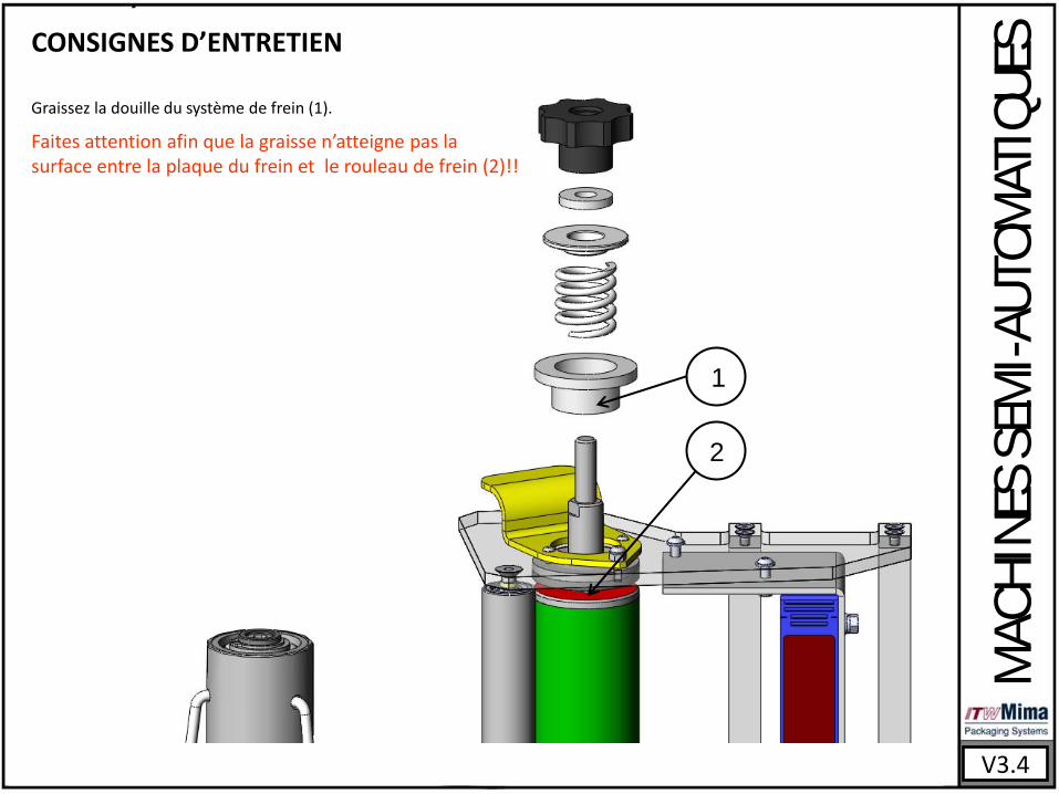
Graissez la douille du système de frein (1).
Faites attention afin que la graisse n’atteigne pas la surface entre la plaque du frein et le rouleau de frein (2)!!

Instrucciones de servicio y montaje Partes de la máquina y esquemas eléctricas
V3.4
G2504 Girotec RDL 1800 G0804 Girotec PL 2000/PLB 2000 G1005 Girotec ST 2000/STB 2000 G1205 Girotec ST 1800 G2905 Girotec ST3 2000 G1304 Girotec WT2 2000 G1504 Girotec WT3 2000
MONTAJE
MÁ
QU
INA
S S
EMIA
UT
OM
ÁT
ICA
S
V3.4
No utilize al aire libre!!No utilize en zonas clasificadas con riesgo de explosión!!
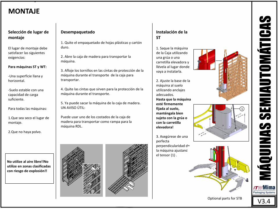
Selección de lugar de montaje El lugar de montaje debe satisfacer las siguientes exigencias: Para máquinas ST y WT: -Una superficie llana y horizontal.
-Suelo estable con una capacidad de carga suficiente.
Para todas las máquinas: 1.Que sea seco el lugar de montaje.
2.Que no haya polvo.
Desempaquetado 1. Quite el empaquetado de hojas plásticas y cartón duro.
2. Abre la caja de madera para transportar la máquina.
3. Afloje los tornillos en las cintas de protección de la máquina durante el transporte de la caja para transportar.
4. Quite las cintas que sirven para la protección de la máquina durante el transporte.
5. Ya puede sacar la máquina de la caja de madera. UN AVISO ÚTIL: Puede usar uno de los costados de la caja de madera para transportar como rampa para la máquina RDL.
Instalación de la ST 1. Saque la máquina de la Caja utilizando una grúa o una carretilla elevadora y llévela al lugar donde vaya a instalarla.
2. Ajuste la base de la máquina al suelo utilizando anclajes adecuados. Hasta que la máquina esté firmemente fijada al suelo, manténgala bien sujeta con la grúa o con la carretilla elevadora! 3. Asegúrese de una perfecta perpendicularidad de la máquina ajustando el tensor (1) .
1
Optional parts for STB
MONTAJE
V3.4
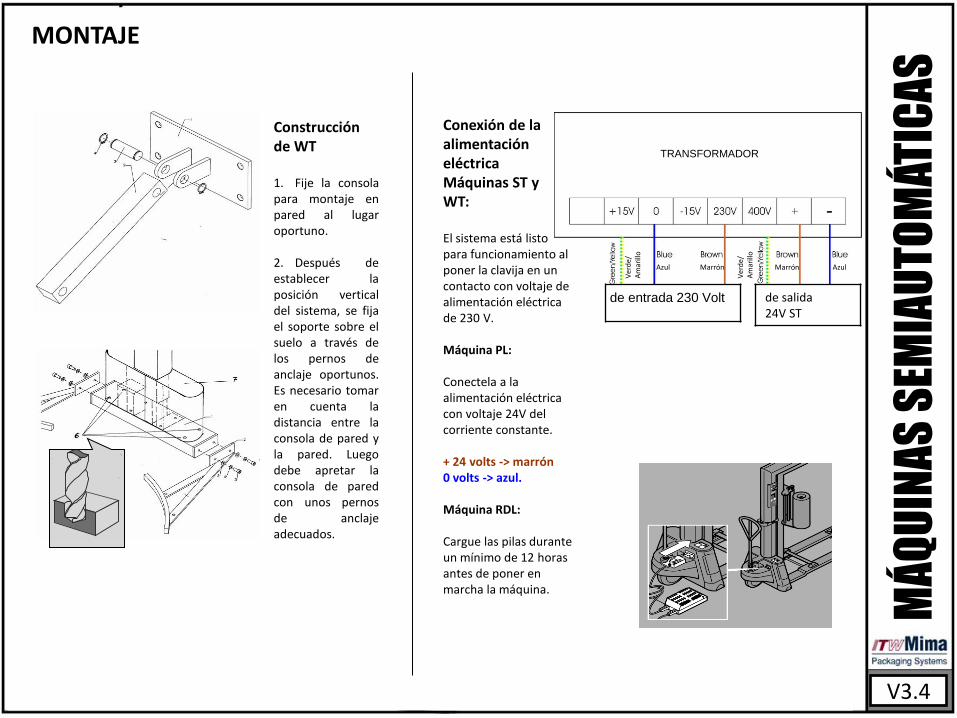
Construcción de WT 1. Fije la consola para montaje en pared al lugar oportuno. 2. Después de establecer la posición vertical del sistema, se fija el soporte sobre el suelo a través de los pernos de anclaje oportunos. Es necesario tomar en cuenta la distancia entre la consola de pared y la pared. Luego debe apretar la consola de pared con unos pernos de anclaje adecuados.
MÁ
QU
INA
S S
EMIA
UT
OM
ÁT
ICA
S
de entrada 230 Volt de salida 24V ST
TRANSFORMADOR
Ver
de/
A
mar
illo
Azul Marrón Marrón Azul
Ver
de/
A
mar
illo
Conexión de la alimentación eléctrica Máquinas ST y WT: El sistema está listo para funcionamiento al poner la clavija en un contacto con voltaje de alimentación eléctrica de 230 V. Máquina PL: Conectela a la alimentación eléctrica con voltaje 24V del corriente constante. + 24 volts -> marrón 0 volts -> azul. Máquina RDL: Cargue las pilas durante un mínimo de 12 horas antes de poner en marcha la máquina.
INSTRUCCIONES PARA MANTENIMINTO
V3.4
Semanalmente
Mensualmente
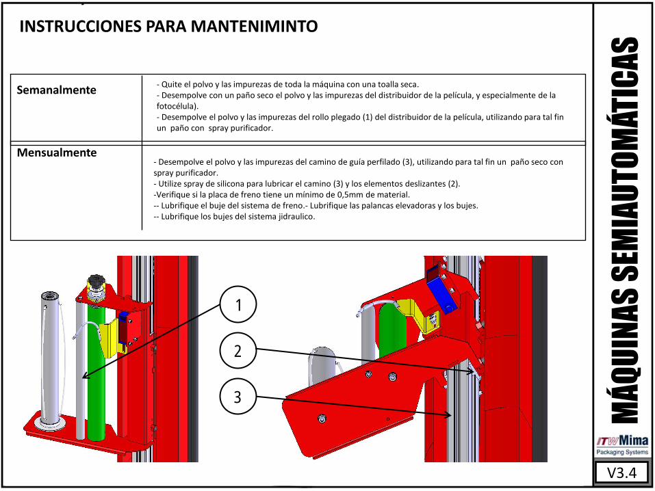
- Quite el polvo y las impurezas de toda la máquina con una toalla seca. - Desempolve con un paño seco el polvo y las impurezas del distribuidor de la película, y especialmente de la fotocélula). - Desempolve el polvo y las impurezas del rollo plegado (1) del distribuidor de la película, utilizando para tal fin un paño con spray purificador.
- Desempolve el polvo y las impurezas del camino de guía perfilado (3), utilizando para tal fin un paño seco con spray purificador. - Utilize spray de silicona para lubricar el camino (3) y los elementos deslizantes (2). -Verifique si la placa de freno tiene un mínimo de 0,5mm de material. -- Lubrifique el buje del sistema de freno.- Lubrifique las palancas elevadoras y los bujes. -- Lubrifique los bujes del sistema jidraulico.
MÁ
QU
INA
S S
EMIA
UT
OM
ÁT
ICA
S
1
2
3
V3.4
INSTRUCCIONES DE MANTENIMIENTO
Verifique si la placa de de freno tiene un mínimo de 0,5 mm de material.
MÁ
QU
INA
S S
EMIA
UT
OM
ÁT
ICA
S
a
Funcionalidad del sistema de freno de la película.
V3.4
INSTRUCCIONES PARA MANTENIMIENTO
MÁ
QU
INA
S S
EMIA
UT
OM
ÁT
ICA
S
1
2
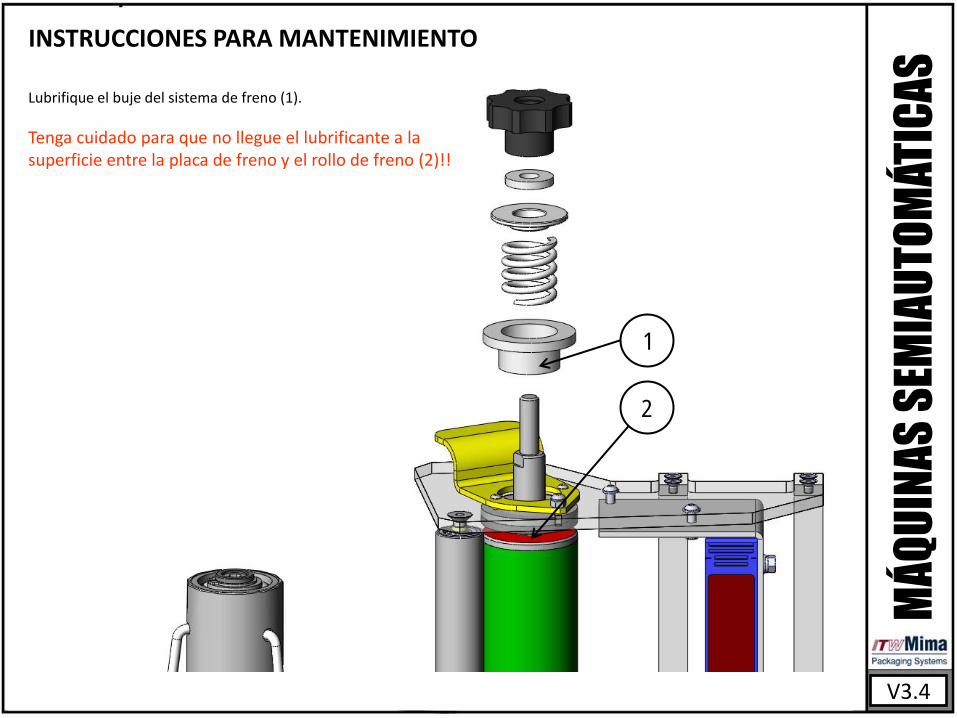
Lubrifique el buje del sistema de freno (1).
Tenga cuidado para que no llegue el lubrificante a la superficie entre la placa de freno y el rollo de freno (2)!!
AB
1
22
4
56
7
8
1314
15
3
16
17
18
1920 21
232
A
9
10
11
12
25
26
B
27
G0153700
04.04.2006
Girotec RDL1800
200 kg1:15PBaPBa Model Number
Page2 / 3
Drawing Number
Date
Replaced Scale
Description
DrawnDesigner Weight
This
doc
umen
t mus
t not
be
copi
ed w
ithou
t ou
r writ
ten
prem
issi
on a
nd th
e co
nten
ts th
ereo
f m
ust n
ot b
e im
pert
ed to
a th
ird p
arty
nor
be
used
fo
r any
una
utho
rized
pur
pose
con
trav
entio
n w
ill b
e pr
osec
uted
ITW
Mim
a Pa
ckag
ing
Syst
ems
540
210
165
1350210
720
2050 - Rotation diameter
1650 - Wrapping diameter
180 - Film diameter
1000
- Pa
llet d
imen
sion
1200 - Pallet dimension
1562
44
1056
335
1895
G0153700Girotec RDL1800
200 kg1:10PBa Model Number
Page3 / 3
Drawing Number
Date
Replaced Scale
Description
DrawnDesigner Weight
This
doc
umen
t mus
t not
be
copi
ed w
ithou
t ou
r writ
ten
prem
issi
on a
nd th
e co
nten
ts th
ereo
f m
ust n
ot b
e im
pert
ed to
a th
ird p
arty
nor
be
used
fo
r any
una
utho
rized
pur
pose
con
trav
entio
n w
ill b
e pr
osec
uted
ITW
Mim
a Pa
ckag
ing
Syst
ems
PBa
04.04.2006
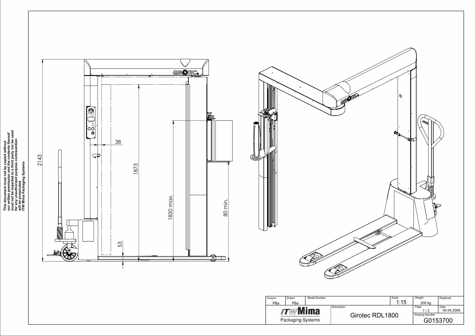
2143
53
80m
in.
1850
max
.
3818
73
Girotec RDL1800G0153700
04.04.2006
200 kg1:15PBaPBa Model Number
Page1 / 3
Drawing Number
Date
Replaced Scale
Description
DrawnDesigner Weight
This
doc
umen
t mus
t not
be
copi
ed w
ithou
t ou
r writ
ten
prem
issi
on a
nd th
e co
nten
ts th
ereo
f m
ust n
ot b
e im
pert
ed to
a th
ird p
arty
nor
be
used
fo
r any
una
utho
rized
pur
pose
con
trav
entio
n w
ill b
e pr
osec
uted
ITW
Mim
a Pa
ckag
ing
Syst
ems
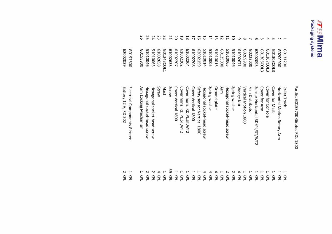
1G
01
31
20
0P
allet Truck
1K
PL
2G
02
00
90
0H
orizo
ntal M
otio
n R
otary A
rm1
KP
L
3G
01
30
8C
OL3
Co
ver for M
ast1
KP
L
4G
01
30
7C
OL3
Co
ver for C
on
sole
1K
PL
5G
01
30
6C
OL3
Co
ver for A
rm1
KP
L
66
20
02
09
3Sen
sor H
orizo
ntal R
D/P
L/ST/WT2
1K
PL
7G
02
23
00
0Film
Distrib
uto
r1
KP
L
8G
02
09
90
0V
ertical Mo
tion
18
00
1K
PL
96
10
02
67
1W
ed
ge Nu
t4
KP
L
10
51
01
00
46
Sprin
g wash
er2
KP
L
11
51
01
00
65
Hexago
nal so
cket-h
ead screw
2K
PL
12
G0
12
50
00
Arm
1K
PL
13
51
01
00
15
Gro
un
d p
late4
KP
L
14
51
01
00
05
Sprin
g wash
er4
KP
L
15
51
01
00
14
Hexago
nal so
cket-h
ead screw
4K
PL
16
62
00
21
59
Safety sen
sor V
ertical 18
00
1K
PL
17
61
00
22
08
Co
ver Vertical 1
80
01
KP
L
18
61
00
22
04
Co
ver ho
riz. RD
,PL,ST,W
T21
KP
L
19
61
00
22
02
Co
ver ho
riz. RD
,PL,ST,W
T21
KP
L
20
61
00
22
07
Co
ver Vertical 1
80
01
KP
L
21
61
00
26
33
Screw5
9K
PL
22
G0
12
43
CO
L1M
ast1
KP
L
23
61
00
26
58
Screw4
KP
L
24
51
01
00
65
Hexago
nal so
cket-h
ead screw
2K
PL
25
51
01
00
46
Hexago
nal so
cket-h
ead screw
2K
PL
26
G0
15
59
00
Arm
Lockin
g Mech
anism
1K
PL
G0
19
76
00
Electrical Co
mp
on
ents G
irote
c1
KP
L
62
00
20
39
Batte
ry 12
V, R
D 2
02
2K
PL
Partlist G
01
53
70
0 G
irote
c RD
L 18
00
60
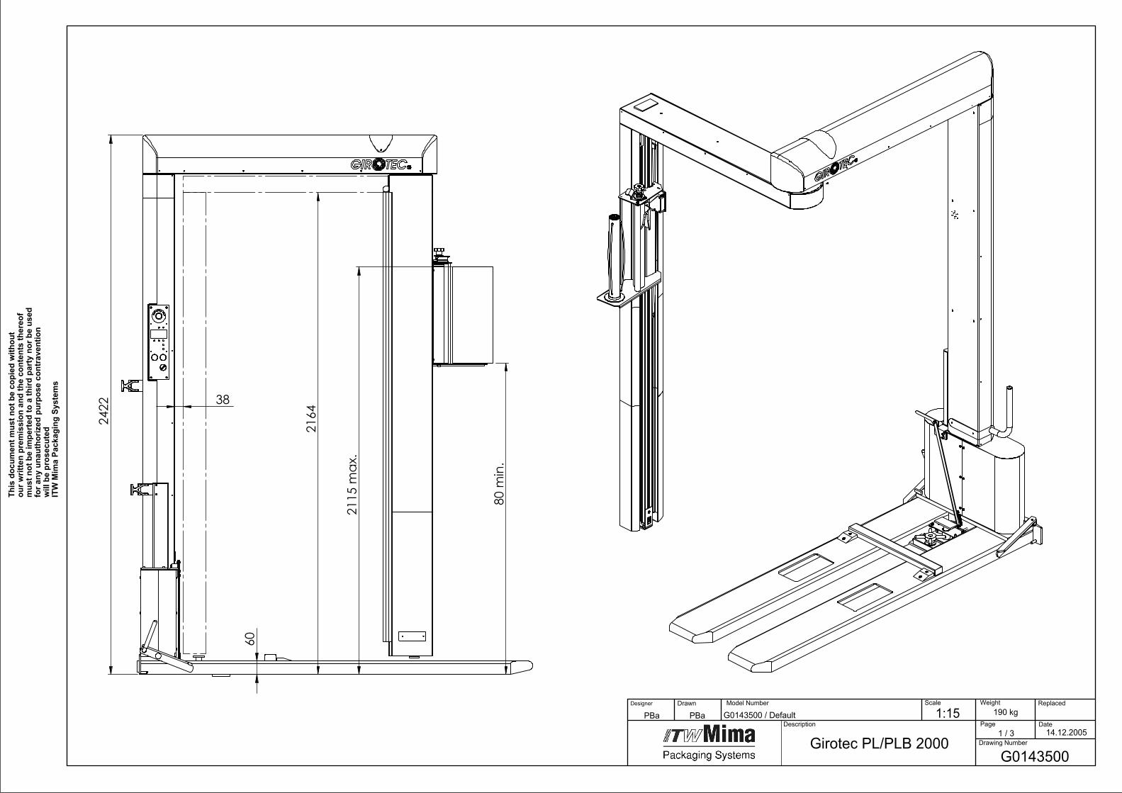
2422
80 m
in.
2115
max
.
2164
38
Girotec PL/PLB 2000G0143500
14.12.2005
1:15 190 kg Model Number
Page1 / 3
Drawing Number
Date
Replaced Scale
Description
DrawnDesigner
This
doc
umen
t mus
t not
be
copi
ed w
ithou
t ou
r writ
ten
prem
issi
on a
nd th
e co
nten
ts th
ereo
f m
ust n
ot b
e im
pert
ed to
a th
ird p
arty
nor
be
used
fo
r any
una
utho
rized
pur
pose
con
trav
entio
n w
ill b
e pr
osec
uted
ITW
Mim
a Pa
ckag
ing
Syst
ems
Weight
G0143500 / DefaultPBa PBa
A
1
24
56
7
8
19
3
13
14
15
1617 18
20
24
27
2625
A
9
10
11
12
22
23
G0143500 / DefaultPBaPBa
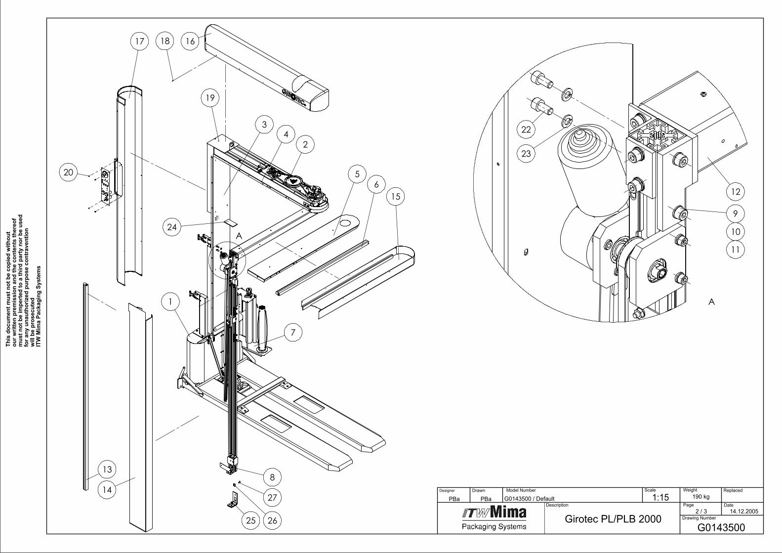
Girotec PL/PLB 2000G0143500
1:15 190 kg Model Number
Page2 / 3
Drawing Number
Date
Replaced Scale
Description
DrawnDesigner Weight
This
doc
umen
t mus
t not
be
copi
ed w
ithou
t ou
r writ
ten
prem
issi
on a
nd th
e co
nten
ts th
ereo
f m
ust n
ot b
e im
pert
ed to
a th
ird p
arty
nor
be
used
fo
r any
una
utho
rized
pur
pose
con
trav
entio
n w
ill b
e pr
osec
uted
ITW
Mim
a Pa
ckag
ing
Syst
ems
14.12.2005
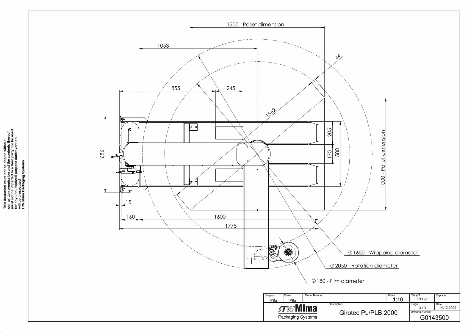
205
580
170
1600160
1775
15
686
245855
2050 - Rotation diameter
1650 - Wrapping diameter
180 - Film diameter
1000
- Pa
llet d
imen
sion
1200 - Pallet dimension
1562
44
1053
G0143500
14.12.2005
Girotec PL/PLB 2000
190 kg1:10PBaPBa Model Number
Page3 / 3
Drawing Number
Date
Replaced Scale
Description
DrawnDesigner Weight
This
doc
umen
t mus
t not
be
copi
ed w
ithou
t ou
r writ
ten
prem
issi
on a
nd th
e co
nten
ts th
ereo
f m
ust n
ot b
e im
pert
ed to
a th
ird p
arty
nor
be
used
fo
r any
una
utho
rized
pur
pose
con
trav
entio
n w
ill b
e pr
osec
uted
ITW
Mim
a Pa
ckag
ing
Syst
ems

1G
01
43
60
0P
L Stand
1P
cs
1G
01
44
70
0P
LB Stan
d1
Pcs
2G
02
00
90
0H
orizo
ntal M
otio
n R
otary A
rm1
Pcs
3G
01
36
8C
OL3
Co
ver for M
ast 20
00
1P
cs
4G
01
30
7C
OL3
Co
ver for C
on
sole
1P
cs
5G
01
30
6C
OL3
Co
ver for A
rm1
Pcs
66
20
02
09
3Sen
sor H
orizo
ntal R
D/P
L/ST/WT2
1P
cs
7G
02
23
00
0Film
Distrib
uto
r1
Pcs
8G
02
10
00
0V
ertical Mo
tion
20
00
1P
cs
96
10
02
67
1W
ed
ge Nu
t4
Pcs
10
51
01
00
46
Sprin
g Wash
er2
Pcs
11
51
01
00
65
Screw2
Pcs
12
G0
12
50
00
Arm
1P
cs
13
62
00
21
59
Safety sen
sor V
ertical 18
00
1P
cs
14
61
00
22
10
Arm
Co
ver Vertical 2
00
01
Pcs
15
61
00
22
04
Arm
Co
ver ho
riz. RD
,PL,ST,W
T21
Pcs
16
61
00
22
02
Mast C
over H
oriz. R
D,P
L,ST,WT2
1P
cs
17
61
00
22
09
Mast C
over vertical 2
00
01
Pcs
18
61
00
34
47
Self Tapp
ing screw
59
Pcs
19
G0
13
58
CO
L1M
ast 20
00
1P
cs
20
61
00
26
58
Screw4
Pcs
22
51
01
00
65
Screw2
Pcs
23
51
01
00
46
Sprin
g Wash
er2
Pcs
24
G0
14
40
00
Ru
bb
er plate fo
r fixation
1P
cs
25
G0
14
43
00
Leg1
Pcs
26
61
00
26
63
Blo
ck M6
1P
cs
27
61
00
05
56
Sun
k screw1
Pcs
G0
19
76
00
Electrical Co
mp
on
ents G
irote
c1
Pcs
Partlist G
01
43
50
0 G
irote
c PL/P
LB 2
00
0
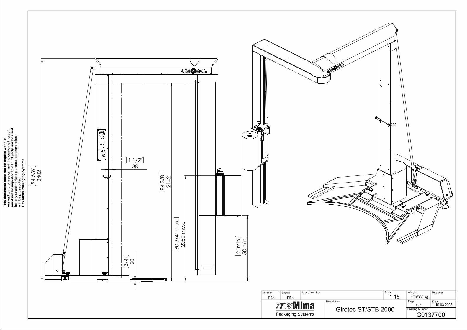
2402
94 5
/8"
203/4"
50m
in.
2"m
in.
2050
max
.80
3/4
"max
.
381 1/2"
2142
84 3
/8"
Girotec ST/STB 2000G0137700
10.03.2008
170/330 kg1:15PBaPBa Model Number
Page1 / 3
Drawing Number
Date
Replaced Scale
Description
DrawnDesigner Weight
This
doc
umen
t mus
t not
be
copi
ed w
ithou
t ou
r writ
ten
prem
issi
on a
nd th
e co
nten
ts th
ereo
f m
ust n
ot b
e im
pert
ed to
a th
ird p
arty
nor
be
used
fo
r any
una
utho
rized
pur
pose
con
trav
entio
n w
ill b
e pr
osec
uted
ITW
Mim
a Pa
ckag
ing
Syst
ems
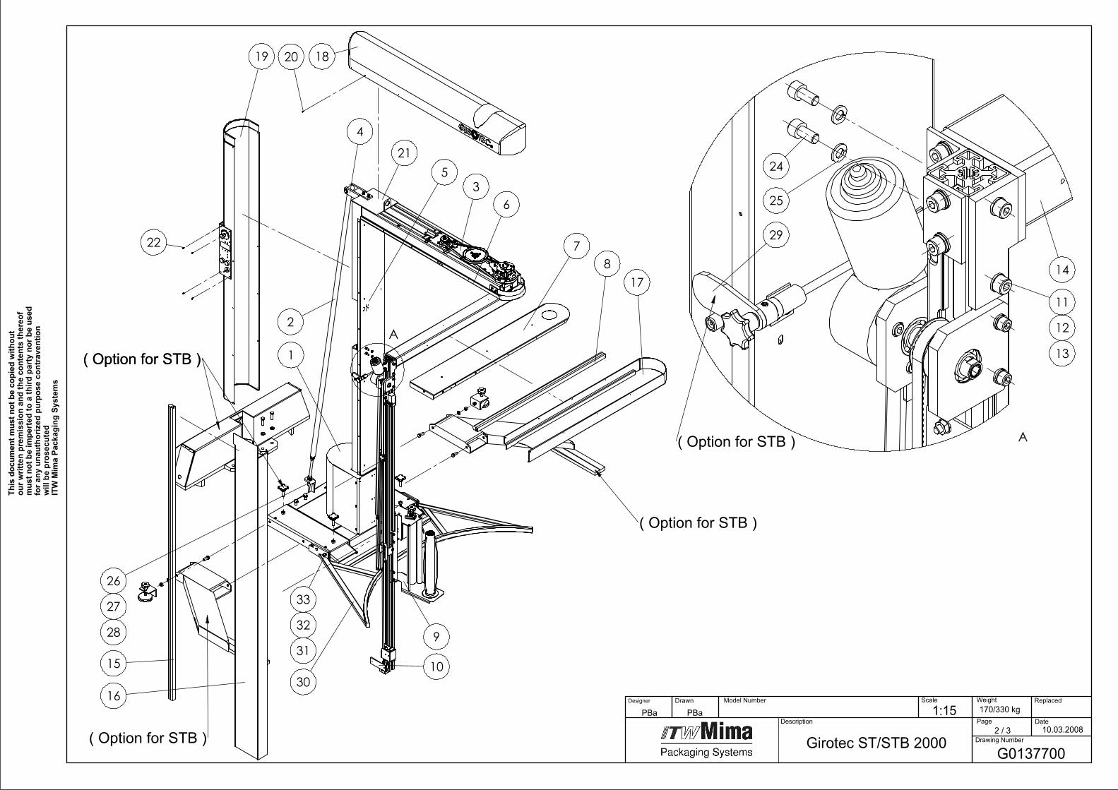
A1
36
78
9
10
5
15
16
17
1819 20
22
4
2
26
27
28
( Option for STB )
( Option for STB )
( Option for STB )( Option for STB )
21
30
33
32
31
A
11
12
13
14
24
25
29
( Option for STB )
G0137700
10.03.2008
Girotec ST/STB 2000
1:15PBaPBa 170/330 kg Model Number
Page2 / 3
Drawing Number
Date
Replaced Scale
Description
DrawnDesigner Weight
This
doc
umen
t mus
t not
be
copi
ed w
ithou
t ou
r writ
ten
prem
issi
on a
nd th
e co
nten
ts th
ereo
f m
ust n
ot b
e im
pert
ed to
a th
ird p
arty
nor
be
used
fo
r any
una
utho
rized
pur
pose
con
trav
entio
n w
ill b
e pr
osec
uted
ITW
Mim
a Pa
ckag
ing
Syst
ems
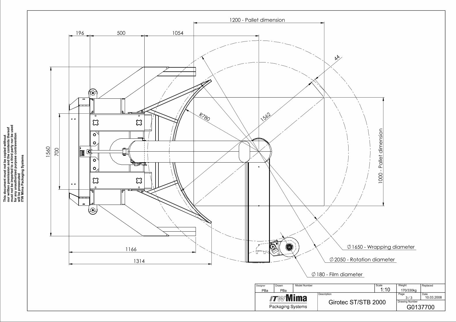
1054500196
1314
1166
1560
R780
700
2050 - Rotation diameter
1650 - Wrapping diameter
180 - Film diameter
1000
- Pa
llet d
imen
sion
1200 - Pallet dimension
1562
44
G0137700
10.03.2008
Girotec ST/STB 2000
170/330kg1:10PBaPBa Model Number
Page3 / 3
Drawing Number
Date
Replaced Scale
Description
DrawnDesigner Weight
This
doc
umen
t mus
t not
be
copi
ed w
ithou
t ou
r writ
ten
prem
issi
on a
nd th
e co
nten
ts th
ereo
f m
ust n
ot b
e im
pert
ed to
a th
ird p
arty
nor
be
used
fo
r any
una
utho
rized
pur
pose
con
trav
entio
n w
ill b
e pr
osec
uted
ITW
Mim
a Pa
ckag
ing
Syst
ems

1G
02
29
70
0B
ase ST1
Pcs
1G
02
29
90
0B
ase STB1
Pcs
2G
01
37
4C
OL1
Ten
sion
er 20
00
1P
cs
3G
02
00
90
0H
orizo
ntal M
otio
n R
otary A
rm1
Pcs
4G
01
35
40
0Ear - Set
1P
cs
5G
01
36
8C
OL3
Co
ver for M
ast 20
00
1P
cs
6G
01
30
7C
OL3
Co
ver for C
on
sole
1P
cs
7G
01
30
6C
OL3
Co
ver for A
rm1
Pcs
86
20
02
09
3Sen
sor H
orizo
ntal R
D/P
L/ST/WT2
1P
cs
9G
02
23
00
0Film
Distrib
uto
r1
Pcs
10
G0
21
00
00
Vertical M
otio
n 2
00
01
Pcs
11
61
00
26
71
We
dge N
ut
4P
cs
12
51
01
00
46
Sprin
g Wash
er2
Pcs
13
51
01
00
65
Screw2
Pcs
14
G0
12
50
00
Arm
1P
cs
15
62
00
21
59
Safety Senso
r Vertical 1
80
01
Pcs
16
61
00
22
10
Arm
Co
ver Vertical 2
00
01
Pcs
17
61
00
22
04
Arm
Co
ver ho
riz. RD
,PL,ST,W
T21
Pcs
18
61
00
22
02
Mast C
over H
oriz. R
D,P
L,ST,WT2
1P
cs
19
61
00
22
09
Mast C
over vertical 2
00
01
Pcs
20
61
00
34
47
Self Tapp
ing screw
59
Pcs
21
G0
13
58
CO
L1M
ast 20
00
1P
cs
22
61
00
26
58
Screw4
Pcs
24
51
01
00
65
Screw2
Pcs
25
51
01
00
46
Sprin
g Wash
er2
Pcs
26
51
01
00
22
Wash
er1
Pcs
27
51
01
00
03
Sprin
g Wash
er1
Pcs
28
51
01
00
39
Nu
t1
Pcs
29
G0
15
59
00
Arm
Lockin
g Mech
anism
1P
cs
30
G0
22
96
CO
L2P
allet Frame ST/STB
1P
cs
31
G0
17
53
00
01
Sleeve
4P
cs
32
51
01
00
05
Sprin
g Wash
er4
Pcs
33
51
01
00
76
Screw4
Pcs
G0
19
76
00
Electrical Co
mp
on
ents G
irote
c1
Pcs
Partlist G
01
37
70
0 G
irote
c ST/STB 2
00
0
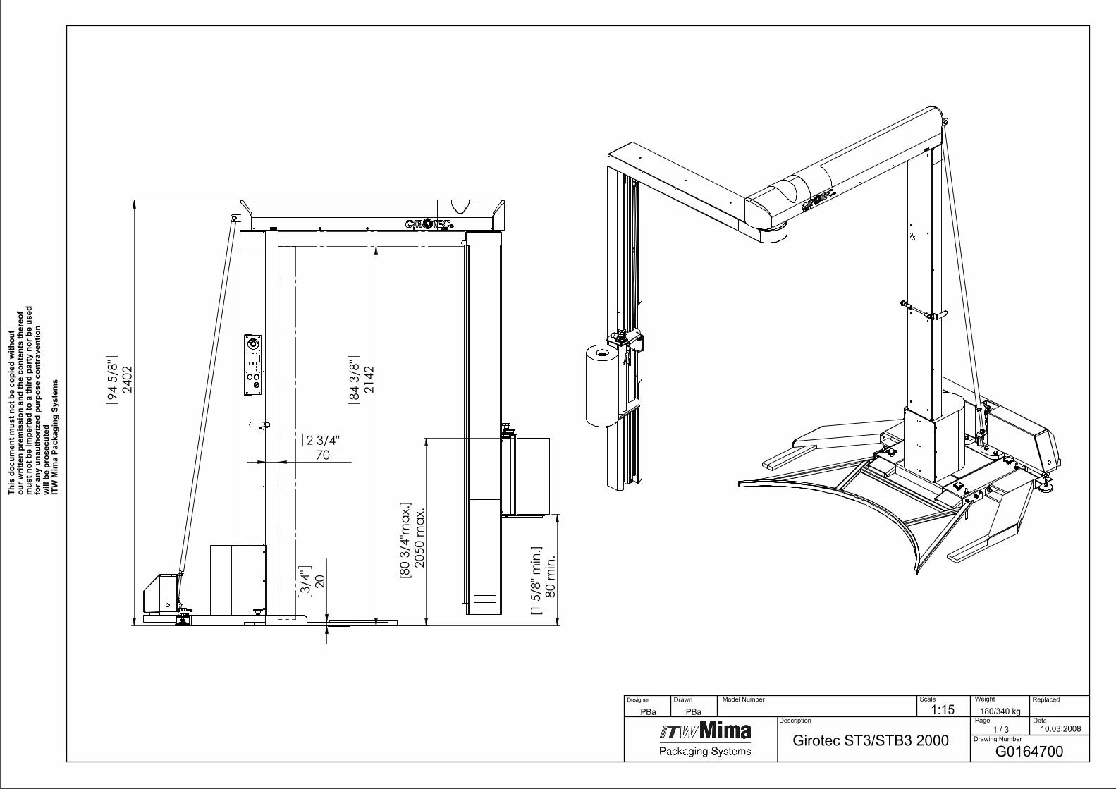
203/4"
2402
94 5
/8"
80
min
.[1
5/8
" min
.]
205
0 m
ax.
[80
3/4"
max
.]
702 3/4"
2142
84 3
/8"
Girotec ST3/STB3 200010.03.2008
180/340 kg1:15PBaPBa Model Number
Page1 / 3
Drawing Number
Date
Replaced Scale
Description
DrawnDesigner Weight
This
doc
umen
t mus
t not
be
copi
ed w
ithou
t ou
r writ
ten
prem
issi
on a
nd th
e co
nten
ts th
ereo
f m
ust n
ot b
e im
pert
ed to
a th
ird p
arty
nor
be
used
fo
r any
una
utho
rized
pur
pose
con
trav
entio
n w
ill b
e pr
osec
uted
ITW
Mim
a Pa
ckag
ing
Syst
ems
G0164700
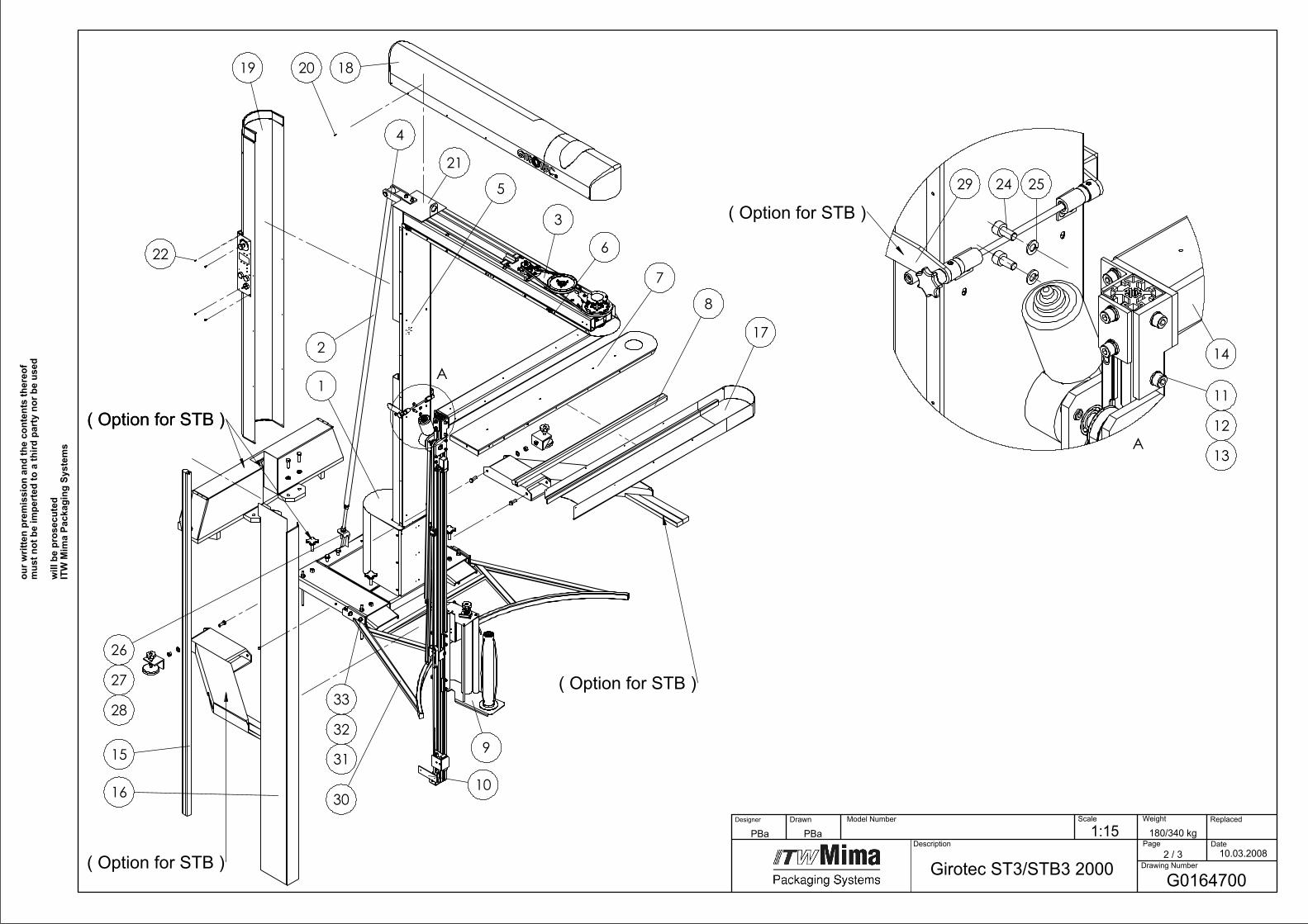
A1
3
6
7
8
9
10
5
15
16
1819 20
22
4
2
26
27
28
( Option for STB )
( Option for STB )
( Option for STB )( Option for STB )
21
17
30
33
32
31
A
11
12
13
14
2529
( Option for STB )
24
10.03.2008
Girotec ST3/STB3 2000
1:15PBaPBa 180/340 kg Model Number
Page2 / 3
Drawing Number
Date
Replaced Scale
Description
DrawnDesigner Weight
our w
ritte
n pr
emis
sion
and
the
cont
ents
ther
eof
mus
t not
be
impe
rted
to a
third
par
ty n
or b
e us
ed
will
be
pros
ecut
edIT
W M
ima
Pack
agin
g Sy
stem
s
G0164700
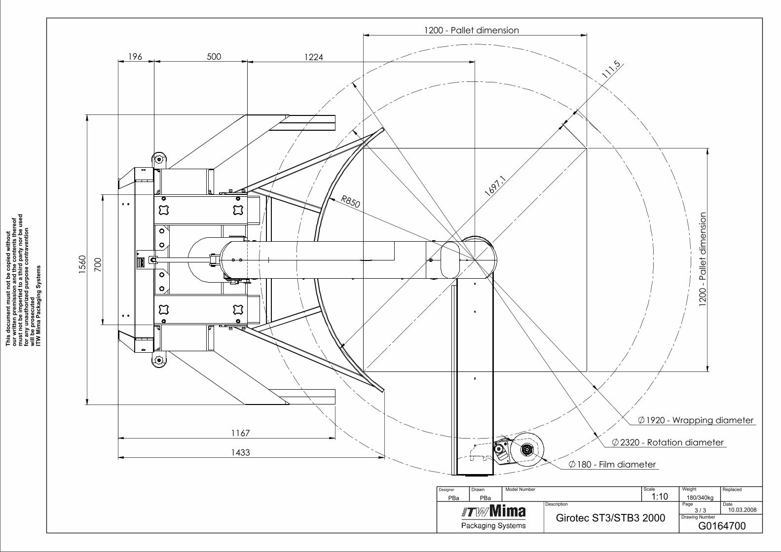
1224
R850
1167
1560
500
1433
196
700
2320 - Rotation diameter
1920 - Wrapping diameter
180 - Film diameter
1200
- Pa
llet d
imen
sion
1200 - Pallet dimension
1697
,1
111,5
10.03.2008Girotec ST3/STB3 2000
180/340kg1:10PBaPBa Model Number
Page3 / 3
Drawing Number
Date
Replaced Scale
Description
DrawnDesigner Weight
This
doc
umen
t mus
t not
be
copi
ed w
ithou
t ou
r writ
ten
prem
issi
on a
nd th
e co
nten
ts th
ereo
f m
ust n
ot b
e im
pert
ed to
a th
ird p
arty
nor
be
used
fo
r any
una
utho
rized
pur
pose
con
trav
entio
n w
ill b
e pr
osec
uted
ITW
Mim
a Pa
ckag
ing
Syst
ems
G0164700

1G
02
29
70
0B
ase ST1
Pcs
1G
02
29
90
0B
ase STB1
Pcs
2G
01
37
4C
OL1
Ten
sion
er 20
00
1P
cs
3G
02
00
90
0H
orizo
ntal M
otio
n R
otary A
rm1
Pcs
4G
01
35
40
0Ear - Set
1P
cs
5G
01
36
8C
OL3
Co
ver for M
ast 20
00
1P
cs
6G
01
36
7C
OL3
Co
ver for C
on
sole W
T31
Pcs
7G
01
36
6C
OL3
Co
ver for A
rm W
T31
Pcs
86
20
02
09
3Sen
sor H
orizo
ntal R
D/P
L/ST/WT2
1P
cs
9G
02
23
00
0Film
Distrib
uto
r1
Pcs
10
G0
21
00
00
Vertical M
otio
n 2
00
01
Pcs
11
61
00
26
71
We
dge N
ut
4P
cs
12
51
01
00
46
Sprin
g Wash
er2
Pcs
13
51
01
00
65
Screw2
Pcs
14
G0
13
62
00
Arm
WT3
1P
cs
15
62
00
21
59
Safety sen
sor V
ertical 18
00
1P
cs
16
61
00
22
10
Co
ver Vertical 2
00
01
Pcs
17
61
00
22
05
Co
ver Ho
rizon
tal WT3
1P
cs
18
61
00
22
03
Co
ver ho
rizon
tal WT3
1P
cs
19
61
00
22
09
Co
ver vertical 20
00
1P
cs
20
61
00
34
47
Self Tapp
ing screw
59
Pcs
21
G0
13
60
CO
L1M
ast 20
00
WT3
1P
cs
22
61
00
26
58
Screw4
Pcs
24
51
01
00
65
Screw2
Pcs
25
51
01
00
46
Sprin
g Wash
er2
Pcs
26
51
01
00
22
Wash
er1
Pcs
27
51
01
00
03
Sprin
g Wash
er1
Pcs
28
51
01
00
39
Nu
t1
Pcs
29
G0
16
65
00
Arm
Lockin
g Mech
anism
GW
35
00
1P
cs
30
G0
22
98
CO
L2P
allet Frame ST3
/STB3
1P
cs
31
G0
17
53
00
01
Sleeve
4P
cs
32
51
01
00
05
Sprin
g Wash
er4
Pcs
33
51
01
00
76
Screw4
Pcs
G0
19
76
00
Electrical Co
mp
on
ents G
irote
c1
Pcs
Partlist G
01
64
70
0 G
irote
c ST3/STB
3 2
00
0
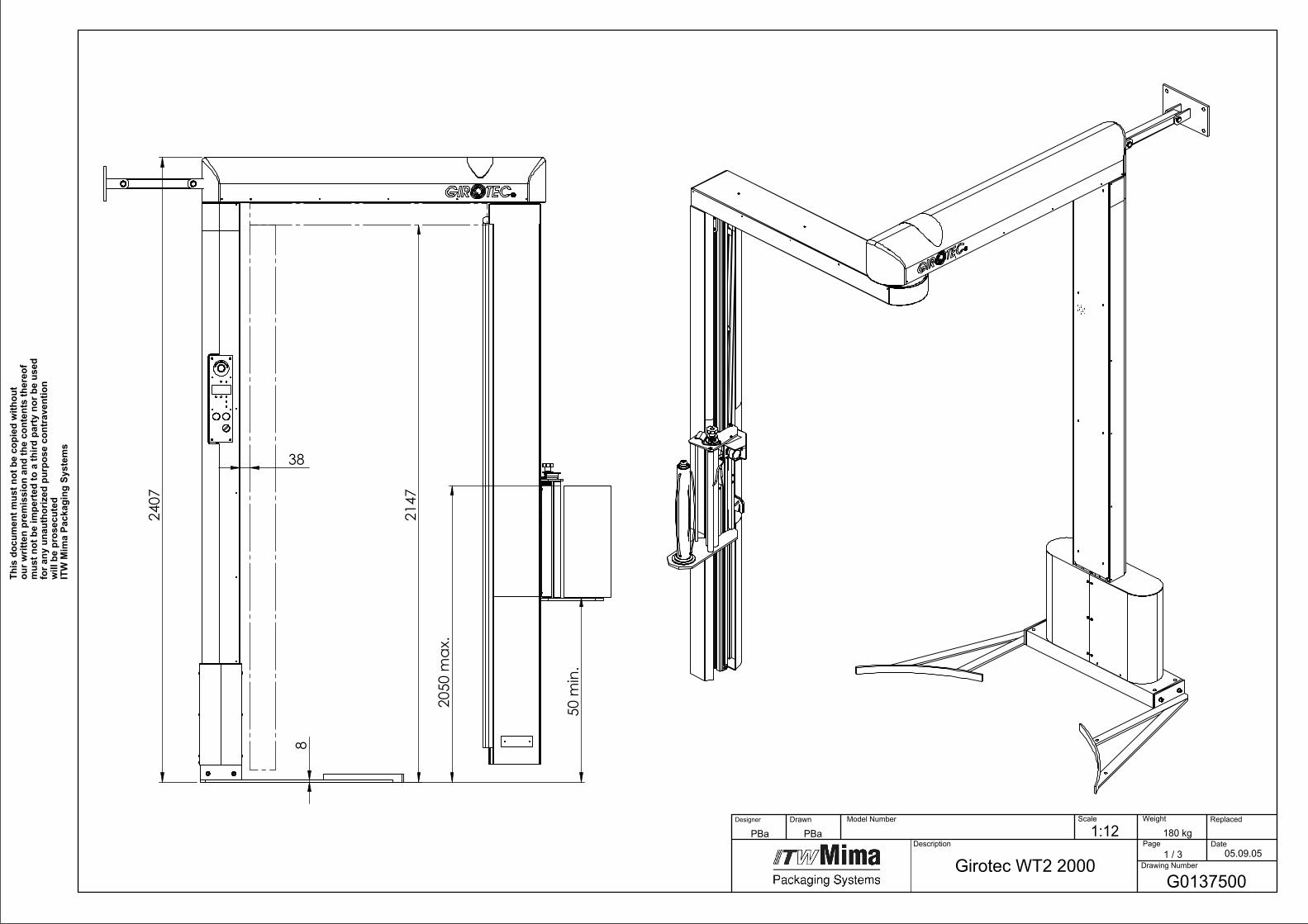
2407
8
50m
in.
2050
max
.38
2147
Girotec WT2 2000G0137500
05.09.05
180 kg1:12PBaPBa Model Number
Page1 / 3
Drawing Number
Date
Replaced Scale
Description
DrawnDesigner Weight
This
doc
umen
t mus
t not
be
copi
ed w
ithou
t ou
r writ
ten
prem
issi
on a
nd th
e co
nten
ts th
ereo
f m
ust n
ot b
e im
pert
ed to
a th
ird p
arty
nor
be
used
fo
r any
una
utho
rized
pur
pose
con
trav
entio
n w
ill b
e pr
osec
uted
ITW
Mim
a Pa
ckag
ing
Syst
ems
A
1
25
67
8
9
4
14
15
16
1718 19
21
320
25
26
29
28
27
A
10
11
12
13
23
24
G0137500
05.09.05Girotec WT2 2000
1:15PBaPBa 180 kg Model Number
Page2 / 3
Drawing Number
Date
Replaced Scale
Description
DrawnDesigner Weight
This
doc
umen
t mus
t not
be
copi
ed w
ithou
t ou
r writ
ten
prem
issi
on a
nd th
e co
nten
ts th
ereo
f m
ust n
ot b
e im
pert
ed to
a th
ird p
arty
nor
be
used
fo
r any
una
utho
rized
pur
pose
con
trav
entio
n w
ill b
e pr
osec
uted
ITW
Mim
a Pa
ckag
ing
Syst
ems
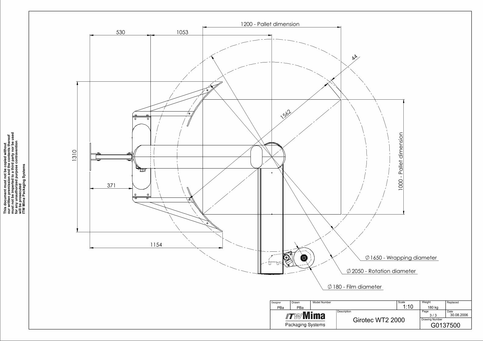
530
1310
1154
371
2050 - Rotation diameter
1650 - Wrapping diameter
180 - Film diameter
1000
- Pa
llet d
imen
sion
1200 - Pallet dimension
1562
44
1053
G0137500
30.08.2006Girotec WT2 2000
180 kg1:10PBaPBa Model Number
Page3 / 3
Drawing Number
Date
Replaced Scale
Description
DrawnDesigner Weight
This
doc
umen
t mus
t not
be
copi
ed w
ithou
t ou
r writ
ten
prem
issi
on a
nd th
e co
nten
ts th
ereo
f m
ust n
ot b
e im
pert
ed to
a th
ird p
arty
nor
be
used
fo
r any
una
utho
rized
pur
pose
con
trav
entio
n w
ill b
e pr
osec
uted
ITW
Mim
a Pa
ckag
ing
Syst
ems

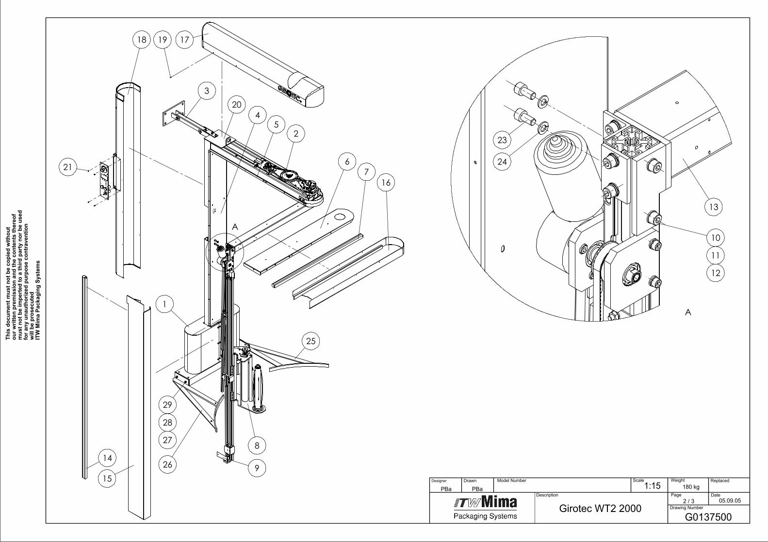
1G
02
30
70
0Stan
d W
T1
Pcs
2G
02
00
90
0H
orizo
ntal M
otio
n R
otary A
rm1
Pcs
3G
01
34
70
0W
all Mo
un
ting
1P
cs
4G
01
36
8C
OL3
Co
ver for M
ast 20
00
1P
cs
5G
01
30
7C
OL3
Co
ver for C
on
sole
1P
cs
6G
01
30
6C
OL3
Co
ver for A
rm1
Pcs
76
20
02
09
3Sen
sor H
orizo
ntal R
D/P
L/ST/WT2
1P
cs
8G
02
23
00
0Film
Distrib
uto
r1
Pcs
9G
02
10
00
0V
ertical Mo
tion
20
00
1P
cs
10
61
00
26
71
We
dge N
ut
4P
cs
11
51
01
00
46
Sprin
g Wash
er2
Pcs
12
51
01
00
65
Wash
er2
Pcs
13
G0
12
50
00
Arm
1P
cs
14
62
00
21
59
Safety sen
sor V
ertical 18
00
1P
cs
15
61
00
22
10
Arm
Co
ver Vertical 2
00
01
Pcs
16
61
00
22
04
Arm
Co
ver ho
riz. RD
,PL,ST,W
T21
Pcs
17
61
00
22
02
Mast C
over H
oriz. R
D,P
L,ST,WT2
1P
cs
18
61
00
22
09
Mast C
over vertical 2
00
01
Pcs
19
61
00
34
47
Self Tapp
ing screw
59
Pcs
20
G0
13
58
CO
L1M
ast 20
00
1P
cs
21
61
00
26
58
Screw2
Pcs
23
51
01
00
65
Screw2
Pcs
24
51
01
00
46
Sprin
g Wash
er2
Pcs
25
G0
13
40
CO
L2R
ight Fram
e1
Pcs
26
G0
13
39
CO
L2Left Fram
e1
Pcs
27
51
01
00
20
Wash
er4
Pcs
28
51
01
00
46
Sprin
g Wash
er4
Pcs
29
51
01
00
65
Screw4
Pcs
G0
19
76
00
Electrical Co
mp
on
ents G
irote
c1
Pcs
Partlist G
01
37
50
0 G
irote
c WT2
20
00
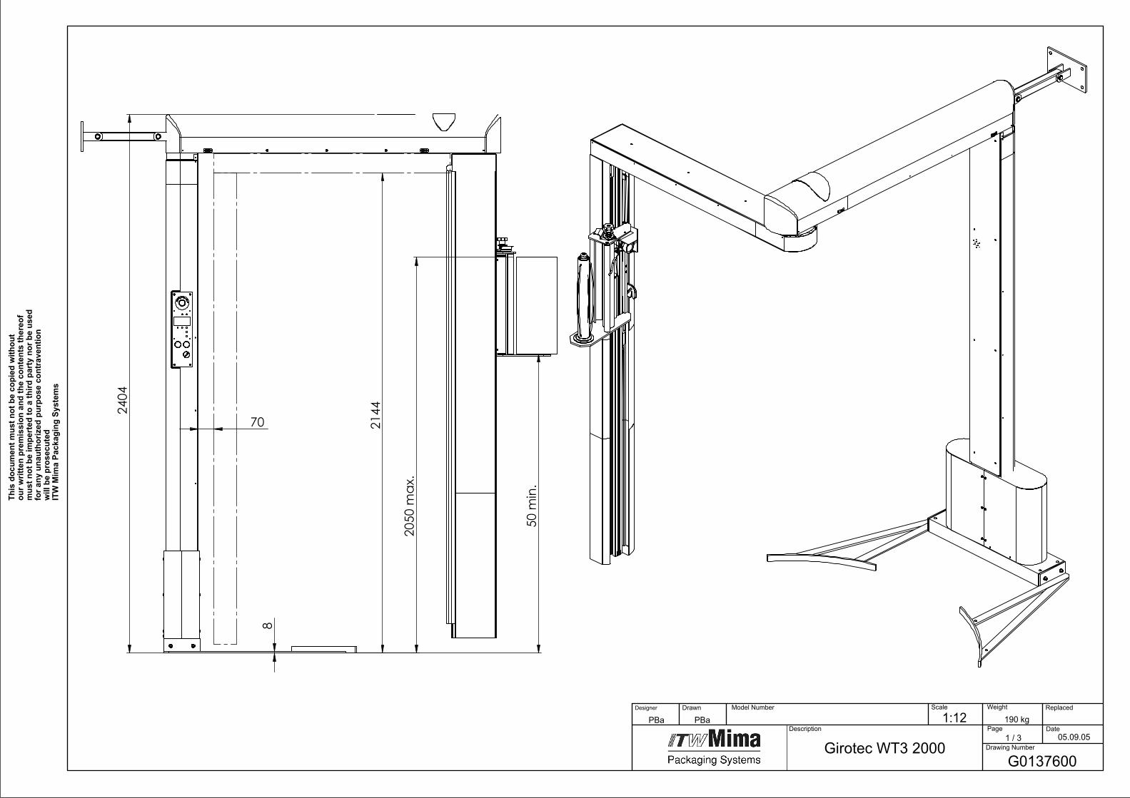
2404
50m
in.
2050
max
.
8
2144
70
Girotec WT3 2000G0137600
05.09.05
190 kg1:12PBaPBa Model Number
Page1 / 3
Drawing Number
Date
Replaced Scale
Description
DrawnDesigner Weight
This
doc
umen
t mus
t not
be
copi
ed w
ithou
t ou
r writ
ten
prem
issi
on a
nd th
e co
nten
ts th
ereo
f m
ust n
ot b
e im
pert
ed to
a th
ird p
arty
nor
be
used
fo
r any
una
utho
rized
pur
pose
con
trav
entio
n w
ill b
e pr
osec
uted
ITW
Mim
a Pa
ckag
ing
Syst
ems
A
1
25
67
8
9
4
14
16
1718 19
21
3
15
20
25
26
29
28
27
A
10
11
12
13
23
24
G0137600
05.09.05Girotec WT3 2000
190kg1:15PBaPBa Model Number
Page2 / 3
Drawing Number
Date
Replaced Scale
Description
DrawnDesigner Weight
our w
ritte
n pr
emis
sion
and
the
cont
ents
ther
eof
mus
t not
be
impe
rted
to a
third
par
ty n
or b
e us
ed
will
be
pros
ecut
edIT
W M
ima
Pack
agin
g Sy
stem
s
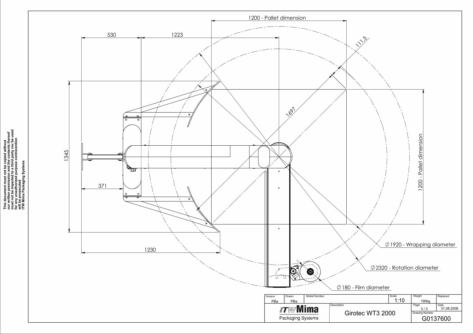
530
1345
1230
371
2320 - Rotation diameter
1920 - Wrapping diameter
180 - Film diameter
1200
- Pa
llet d
imen
sion
1200 - Pallet dimension
1697
111,5
1223
G0137600
31.08.2006Girotec WT3 2000
1:10PBaPBa 190kg Model Number
Page3 / 3
Drawing Number
Date
Replaced Scale
Description
DrawnDesigner Weight
This
doc
umen
t mus
t not
be
copi
ed w
ithou
t ou
r writ
ten
prem
issi
on a
nd th
e co
nten
ts th
ereo
f m
ust n
ot b
e im
pert
ed to
a th
ird p
arty
nor
be
used
fo
r any
una
utho
rized
pur
pose
con
trav
entio
n w
ill b
e pr
osec
uted
ITW
Mim
a Pa
ckag
ing
Syst
ems

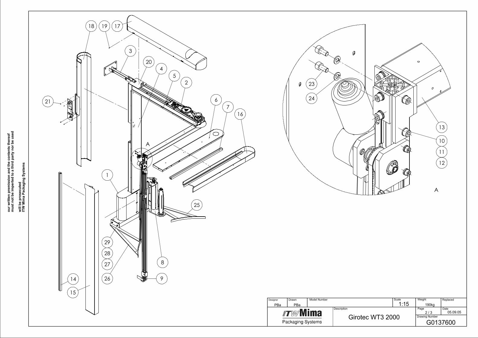
1G
02
30
70
0Stan
d W
T1
Pcs
2G
02
00
90
0H
orizo
ntal M
otio
n R
otary A
rm1
Pcs
3G
01
34
70
0W
all Mo
un
ting
1P
cs
4G
01
36
8C
OL3
Co
ver for M
ast 20
00
1P
cs
5G
01
36
7C
OL3
Co
ver for C
on
sole W
T31
Pcs
6G
01
36
6C
OL3
Co
ver for A
rm W
T31
Pcs
76
20
02
09
3Sen
sor H
orizo
ntal R
D/P
L/ST/WT2
1P
cs
8G
02
23
00
0Film
Distrib
uto
r1
Pcs
9G
02
10
00
0V
ertical Mo
tion
20
00
1P
cs
10
61
00
26
71
We
dge N
ut
4P
cs
11
51
01
00
46
Sprin
g Wash
er2
Pcs
12
51
01
00
65
Screw2
Pcs
13
G0
13
62
00
Arm
WT3
1P
cs
14
62
00
21
59
Safety sen
sor V
ertical 18
00
1P
cs
15
61
00
22
10
Arm
Co
ver Vertical 2
00
01
Pcs
16
61
00
22
05
Arm
Co
ver Ho
rizon
tal WT3
1P
cs
17
61
00
22
03
Mast C
over h
orizo
ntal W
T31
Pcs
18
61
00
22
09
Mast C
over vertical 2
00
01
Pcs
19
61
00
34
47
Self Tapp
ing screw
59
Pcs
20
G0
13
60
CO
L1M
ast 20
00
WT3
1P
cs
21
61
00
26
58
Screw2
Pcs
23
51
01
00
65
Screw2
Pcs
24
51
01
00
46
Sprin
g Wash
er2
Pcs
25
G0
13
43
CO
L2R
ight Fram
e1
Pcs
26
G0
13
42
CO
L2Left Fram
e1
Pcs
27
51
01
00
20
Wash
er4
Pcs
28
51
01
00
46
Sprin
g Wash
er4
Pcs
29
51
01
00
65
Screw4
Pcs
G0
19
76
00
Electrical Co
mp
on
ents G
irote
c1
Pcs
Partlist G
01
37
60
0 G
irote
c WT3
20
00
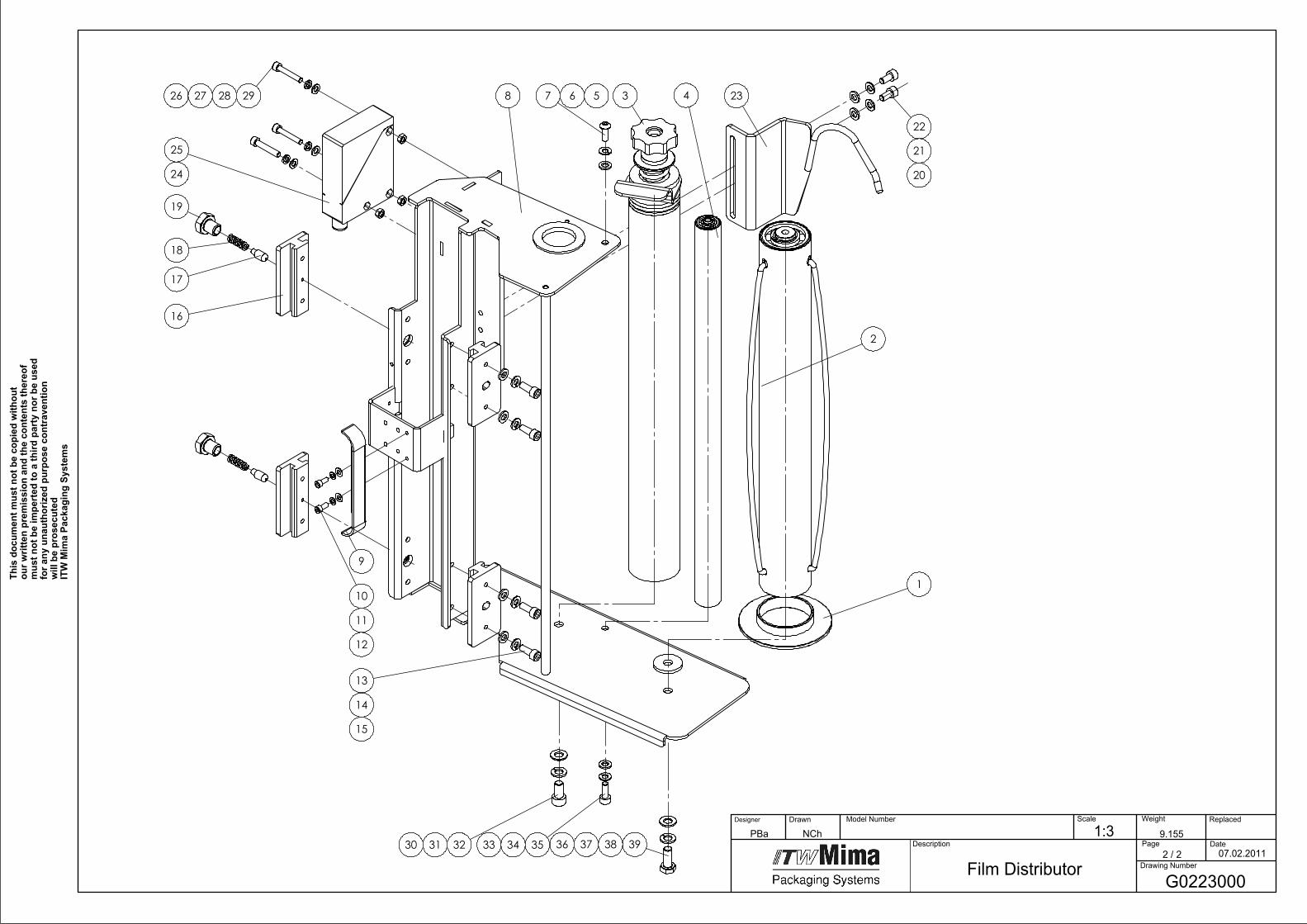
1
2
3 4 23
22
21
20
29282726
25
24
19
18
17
16
9
8
13
14
15
10
11
12
323130 353433
7 6 5
39383736
G0223000
07.02.2011
Film Distributor
9.1551:3NChPBa Model Number
Page2 / 2
Drawing Number
Date
Replaced Scale
Description
DrawnDesigner Weight
This
doc
umen
t mus
t not
be
copi
ed w
ithou
t ou
r writ
ten
prem
issi
on a
nd th
e co
nten
ts th
ereo
f m
ust n
ot b
e im
pert
ed to
a th
ird p
arty
nor
be
used
fo
r any
una
utho
rized
pur
pose
con
trav
entio
n w
ill b
e pr
osec
uted
ITW
Mim
a Pa
ckag
ing
Syst
ems

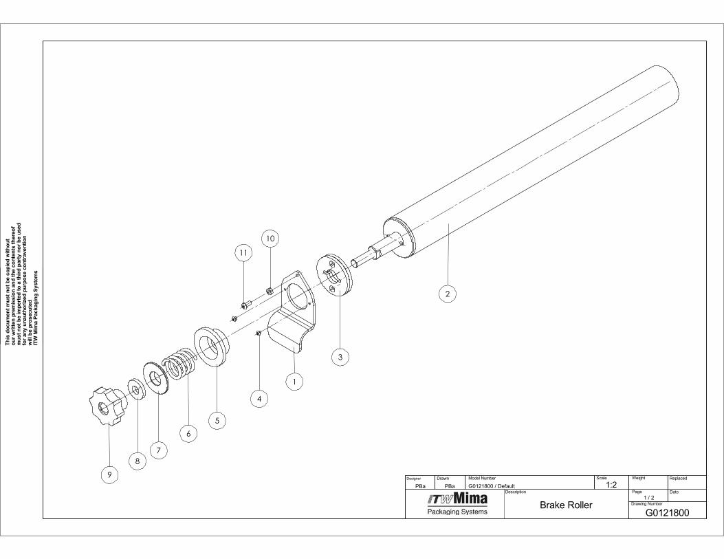
1G
01
20
40
0Slee
ve1
Pcs
2G
01
21
40
0Film
Re
el Ho
lder
1P
cs
3G
01
21
80
0B
rake Ro
ller1
Pcs
4G
01
21
10
0R
oller
1P
cs
56
10
02
65
0Screw
1P
cs
65
10
10
01
3Sp
ring w
asher
1P
cs
75
10
10
01
7G
rou
nd
plate
1P
cs
8G
02
23
1C
OL3
Carrier
1P
cs
9G
01
20
8C
OL1
Cam
1P
cs
10
51
01
10
93
Hexago
n so
cket cap
screw2
Pcs
11
61
00
20
73
Sprin
g wash
er2
Pcs
12
51
01
03
19
Gro
un
d p
late2
Pcs
13
51
01
00
90
Hexago
n so
cket cap
screw4
Pcs
14
51
01
00
13
Sprin
g wash
er4
Pcs
15
51
01
00
17
Gro
un
d p
late4
Pcs
16
G0
22
32
00
Pro
file4
Pcs
17
G0
22
34
00
01
Pin
2P
cs
18
G0
22
33
00
01
Sprin
g2
Pcs
19
G0
22
35
00
01
Gu
idin
g Screw2
Pcs
20
51
01
00
49
Hexago
n so
cket cap
screw2
Pcs
21
51
01
00
13
Sprin
g wash
er2
Pcs
22
51
01
00
17
Gro
un
d p
late2
Pcs
23
G0
16
33
CO
L2R
op
ing D
evice1
Pcs
24
62
00
13
18
Ph
oto
cell1
Pcs
25
62
00
29
19
Cab
le with
Socke
t M1
21
Pcs
26
51
01
04
82
Hexago
n so
cket cap
screw3
Pcs
27
51
01
09
19
Sprin
g Wash
er3
Pcs
28
51
01
01
10
Gro
un
d p
late3
Pcs
29
51
01
01
09
Hexago
n n
ut
3P
cs
30
51
01
01
34
Hexago
n so
cket cap
screw1
Pcs
31
51
01
00
46
Sprin
g wash
er1
Pcs
32
51
01
00
20
Gro
un
d p
late1
Pcs
33
51
01
00
90
Hexago
n so
cket cap
screw1
Pcs
34
51
01
00
13
Sprin
g wash
er1
Pcs
35
51
01
00
17
Gro
un
d p
late1
Pcs
36
51
01
00
19
Hexago
nal screw
,full th
readed
1P
cs
37
51
01
00
46
Sprin
g wash
er1
Pcs
38
51
01
00
20
Gro
un
d p
late1
Pcs
39
61
00
24
54
Gro
un
d p
late1
Pcs
Partlist G
02
23
00
0 Film
Distrib
uto
r
������������� ���
������������ ��������
����������
��������������
����
�������� ���
�!������ �
�������!���� �"��#�
���������� �� ��� ������������� �� �
������ ����������������� ������ �� �� �������
� ��� �������� ��� ���� �������� �������������
���������� ������������������ ����� ����
�������������� ��
��������������������� ��
������������$����
�
�
�
�
��
��
�
��

��������;
<=?=F<<;:����;�
���������;=
=<=?=>$
%�?
��&��=���
?<=ACC<<
��--��;�
�����=���
@<=??F<<
:����;�
���=���
AC=<<?CB>
)���2
?���
B<=??@<<<=
$��#1
=���
C<=??A<<<=
)1����
=���
D<=??B<<<=
)�11���;�
���=���
F<=??C<<<=
+��3��
=���
>C=<<?CBD
����/�
=���
=<B=<=<=D@
��4����;���
=���
==C=<<?CBF
)���2
=���
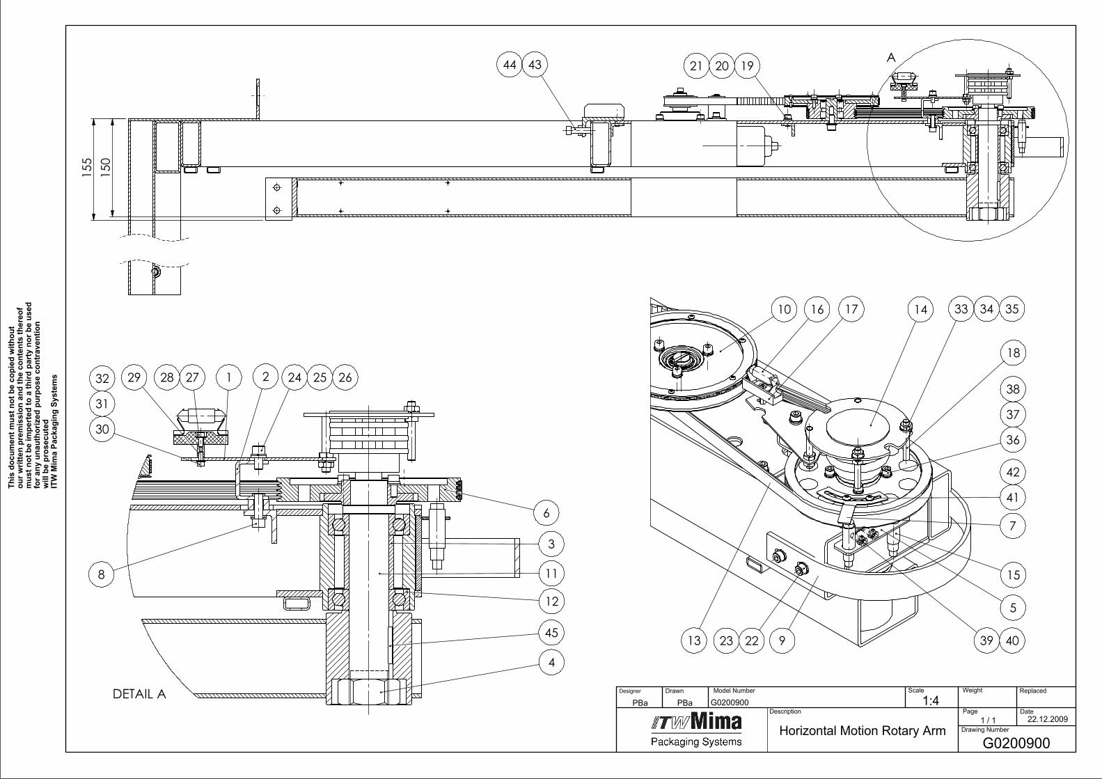
155
150
A1920214344
DETAIL A
1
3
4
2
6
11
24 25 262728
30
31
32 29
45
12
8
5
10 14
15
16 17
18
33 34 35
36
37
38
392223 9 4013
41
7
42
G0200900
Horizontal Motion Rotary ArmG0200900
1:4 Model Number
Page1 / 1
Drawing Number
Date
Replaced Scale
Description
Weight
This
doc
umen
t mus
t not
be
copi
ed w
ithou
t ou
r writ
ten
prem
issi
on a
nd th
e co
nten
ts th
ereo
f m
ust n
ot b
e im
pert
ed to
a th
ird p
arty
nor
be
used
fo
r any
una
utho
rized
pur
pose
con
trav
entio
n w
ill b
e pr
osec
uted
ITW
Mim
a Pa
ckag
ing
Syst
ems
22.12.2009
PBa PBaDesigner Drawn

1G
01
27
2C
OL1
Bo
ard fo
r Co
llector
1P
cs
2G
02
02
0C
OL1
Stand
1P
cs
3G
01
26
70
0R
emo
te Sleeve
1P
cs
4G
01
26
80
00
1N
ut M
30
x1,5
1P
cs
5G
02
06
7C
OL1
Do
ub
le Stand
1P
cs
6G
02
01
70
0En
d D
riving W
hee
l1
Pcs
7G
02
05
8C
OL1
Co
ntact P
late1
Pcs
85
10
10
09
0Screw
1P
cs
9G
01
59
9C
OL1
Sup
po
rt for U
pp
er Co
ver1
Pcs
10
G0
20
10
00
Drivin
g Un
it1
Pcs
11
G0
12
65
00
Ou
tpu
t Shaft
1P
cs
12
51
01
70
96
Ball B
earing
2P
cs
13
61
00
33
71
Micro
V-b
elt1
Pcs
14
62
00
34
63
Slip R
ing
1P
cs
15
62
00
29
86
Ind
uctive Sw
itch2
Pcs
16
62
00
18
46
Bu
lb1
Pcs
17
61
00
19
92
Bu
lb H
old
er1
Pcs
18
61
00
19
97
Stud
2P
cs
19
51
01
00
17
Wash
er6
Pcs
20
51
01
00
13
Sprin
g wash
er6
Pcs
21
51
01
00
49
Screw6
Pcs
22
51
01
00
13
Sprin
g wash
er4
Pcs
23
51
01
00
49
Screw4
Pcs
24
51
01
00
17
Wash
er1
Pcs
25
51
01
00
13
Sprin
g wash
er1
Pcs
26
51
01
00
49
Screw1
Pcs
27
51
01
03
89
Wash
er1
Pcs
28
51
01
11
08
Screw1
Pcs
29
61
00
19
93
Bu
shin
g1
Pcs
30
51
01
11
08
Screw1
Pcs
31
61
00
19
51
Sprin
g wash
er1
Pcs
32
51
01
03
89
Wash
er1
Pcs
33
51
01
00
50
Nu
t 4
Pcs
34
51
01
00
13
Sprin
g wash
er4
Pcs
35
51
01
00
50
Nu
t4
Pcs
36
51
01
01
10
Wash
er4
Pcs
37
51
01
09
19
Sprin
g wash
er4
Pcs
38
51
01
06
26
Screw4
Pcs
39
51
01
09
19
Sprin
g wash
er2
Pcs
40
51
01
06
26
Screw2
Pcs
41
61
00
20
73
Sprin
g wash
er2
Pcs
42
61
00
26
58
Screw2
Pcs
43
51
01
00
41
Nu
t 1
Pcs
44
51
01
01
98
Screw1
Pcs
45
51
01
00
96
We
dge
1P
cs
Partlist G
02
00
90
0 H
orizo
ntal M
otio
n R
otary A
rm
396
495545
165
39
54
A
A
1231323334
240.
7mm
423
0.7m
m3
0.5m
m
A-A 1 2 3 67 8
11
1026 27
282930
4
16
17
18 24
13 19
21
22
23 25
14
15
20
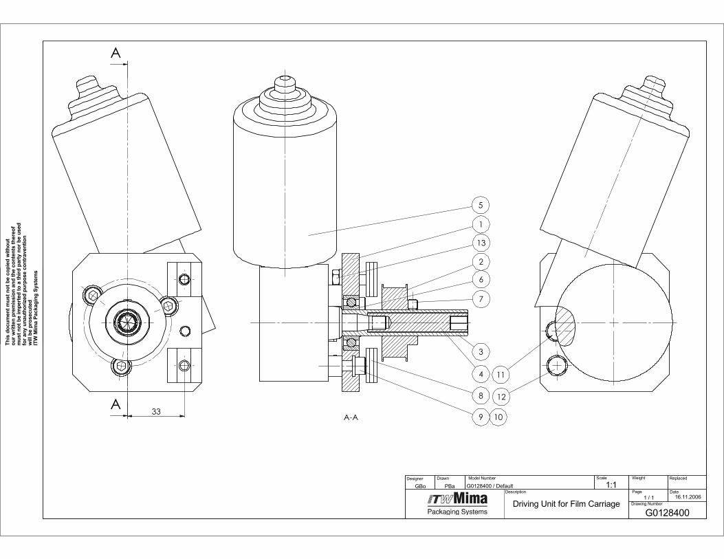
G0201000
24.09.2009
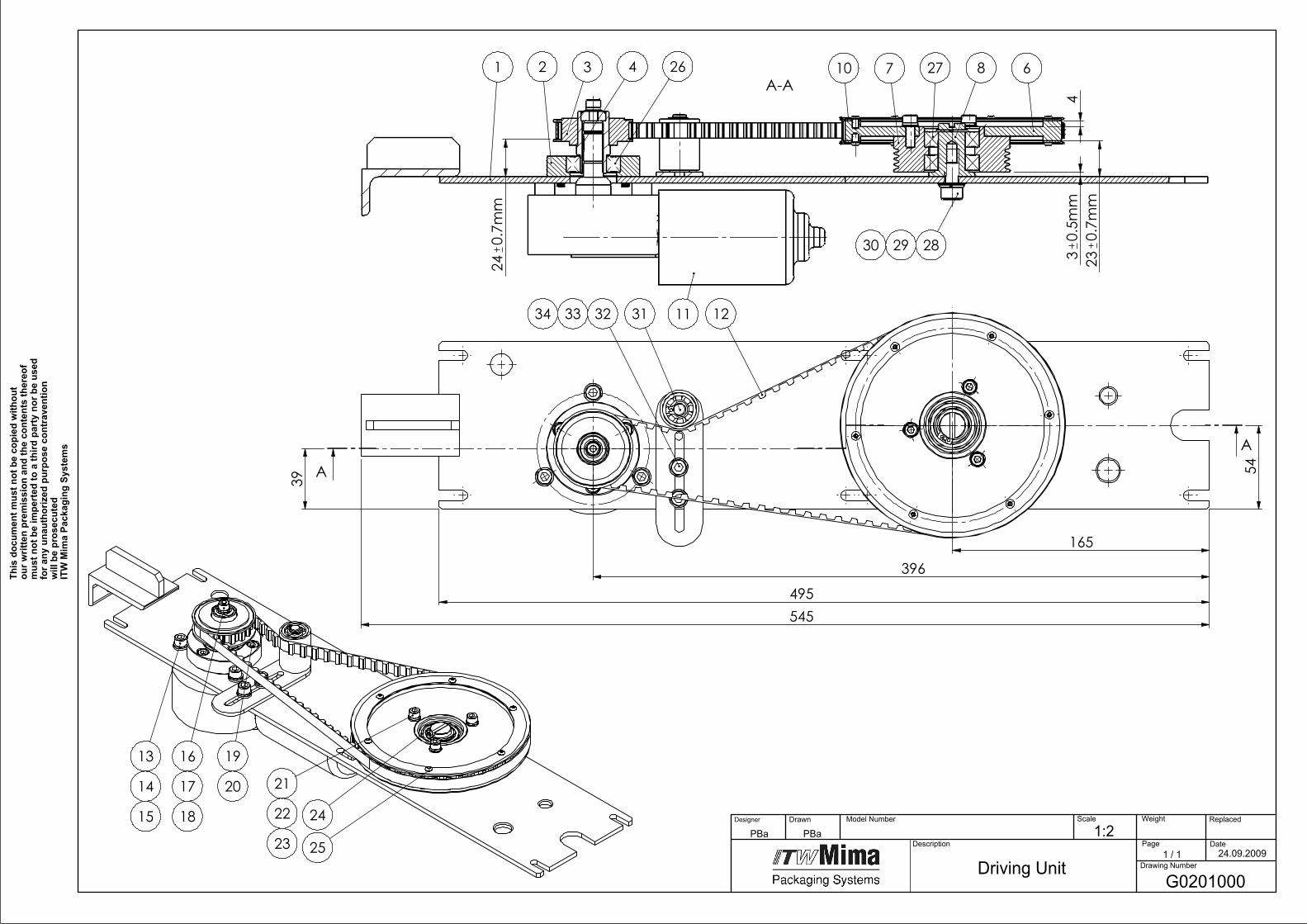
Driving Unit
1:2PBaPBa Model Number
Page1 / 1
Drawing Number
Date
Replaced Scale
Description
DrawnDesigner Weight
This
doc
umen
t mus
t not
be
copi
ed w
ithou
t ou
r writ
ten
prem
issi
on a
nd th
e co
nten
ts th
ereo
f m
ust n
ot b
e im
pert
ed to
a th
ird p
arty
nor
be
used
fo
r any
una
utho
rized
pur
pose
con
trav
entio
n w
ill b
e pr
osec
uted
ITW
Mim
a Pa
ckag
ing
Syst
ems
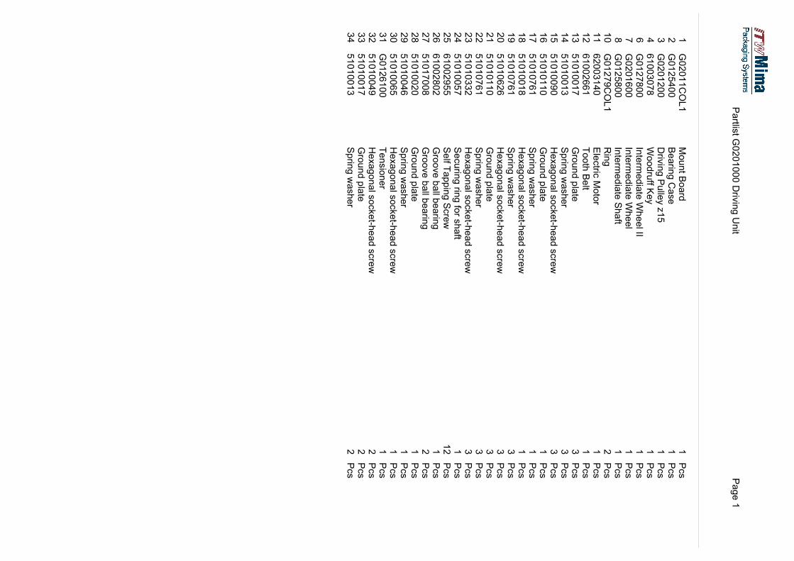
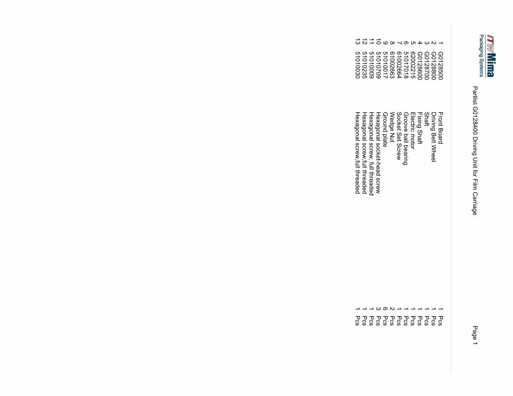
Partlis
t G0201000 Driv
ing Unit
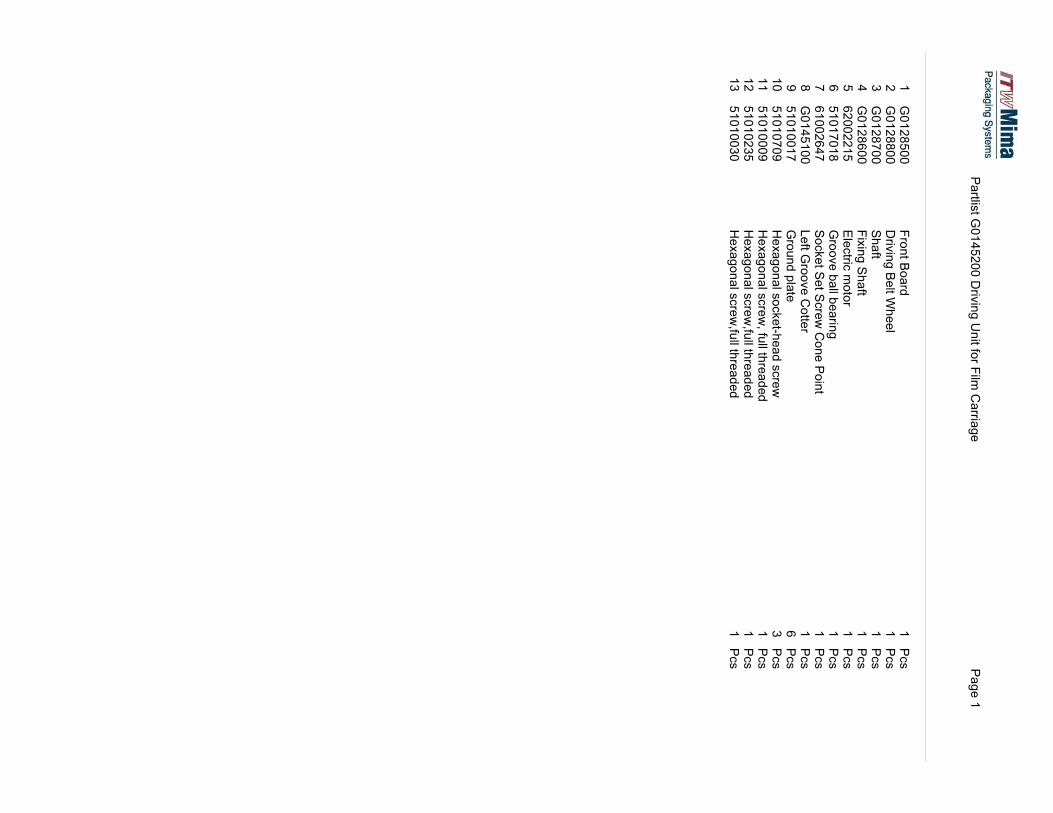
Page 1
1G02011COL1
Mount B
oard
1Pcs
2G0125400
Bearin
g Case
1Pcs
3G0201200
Driv
ing Pulle
y z15
1Pcs
461003078
Woodruff K
ey
1Pcs
6G0127800
Interm
ediate W
heel II
1Pcs
7G0201600
Interm
ediate W
heel
1Pcs
8G0125800
Interm
ediate Shaft
1Pcs
10
G01279COL1
Ring
2Pcs
11
62003140
Electric
Motor
1Pcs
12
61002661
Tooth Belt
1Pcs
13
51010017
Ground plate
3Pcs
14
51010013
Sprin
g washer
3Pcs
15
51010090
Hexagonal socket-h
ead screw
3Pcs
16
51010110
Ground plate
1Pcs
17
51010761
Sprin
g washer
1Pcs
18
51010018
Hexagonal socket-h
ead screw
1Pcs
19
51010761
Sprin
g washer
3Pcs
20
51010626
Hexagonal socket-h
ead screw
3Pcs
21
51010110
Ground plate
3Pcs
22
51010761
Sprin
g washer
3Pcs
23
51010332
Hexagonal socket-h
ead screw
3Pcs
24
51010057
Securin
g rin
g fo
r shaft
1Pcs
25
61002955
Self T
apping Screw
12
Pcs
26
61002802
Groove ball b
earin
g1
Pcs
27
51017008
Groove ball b
earin
g2
Pcs
28
51010020
Ground plate
1Pcs
29
51010046
Sprin
g washer
1Pcs
30
51010065
Hexagonal socket-h
ead screw
1Pcs
31
G0126100
Tensioner
1Pcs
32
51010049
Hexagonal socket-h
ead screw
2Pcs
33
51010017
Ground plate
2Pcs
34
51010013
Sprin
g washer
2Pcs
1 2 3
45
6
78 91011
12
17
16 131415
18 19 20 25262721222324
28
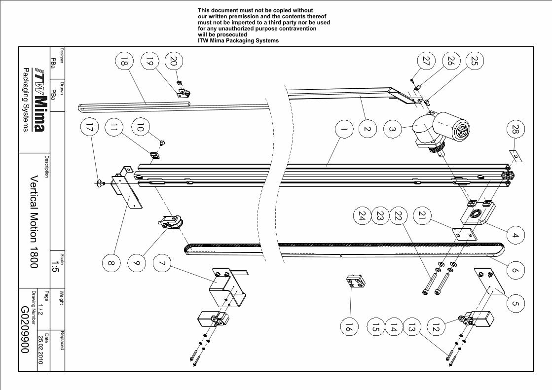
G0209900
25.02.2010Vertical M
otion 1800 1:51 / 2
PBaPBa
Weight
Designer
Draw
n Scale
Replaced
Description
Page D
ate
Draw
ing Num
ber
This document must not be copied without our written premission and the contents thereof must not be imperted to a third party nor be used for any unauthorized purpose contravention will be prosecutedITW Mima Packaging Systems
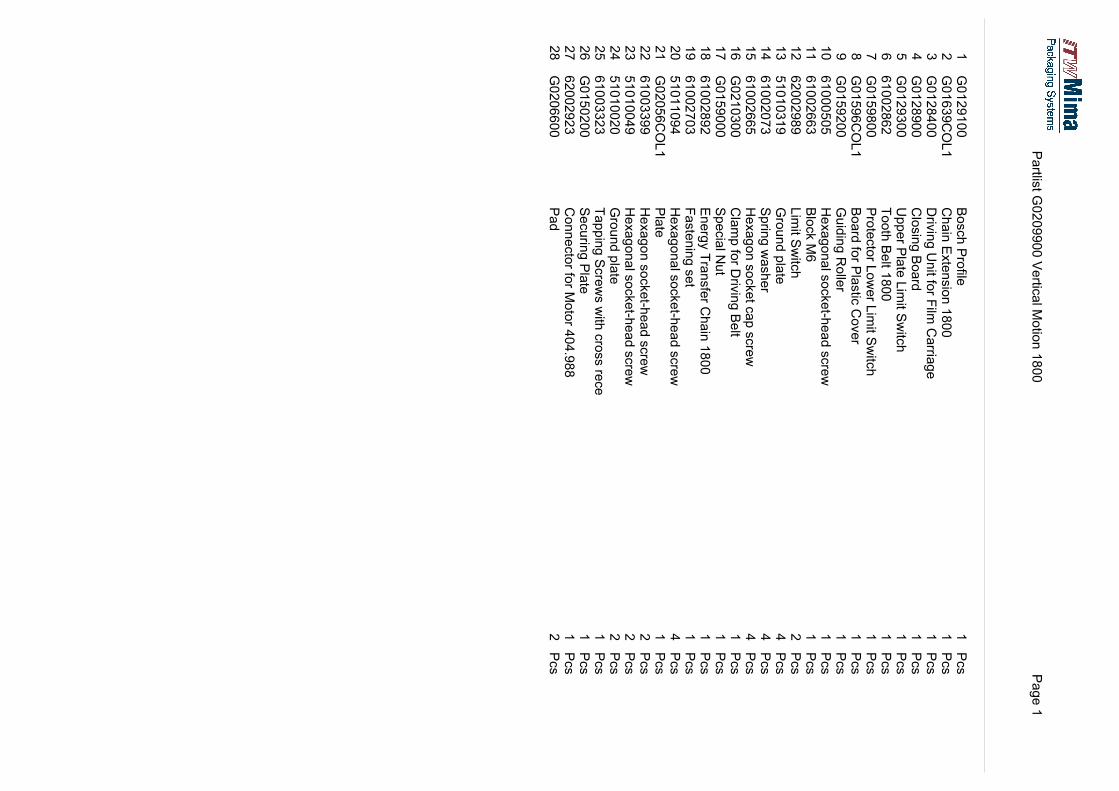
Partlis
t G0209900 Vertic
al M
otion 1800
Page 1
1G0129100
Bosch Profile
1Pcs
2G01639COL1
Chain Extension 1800
1Pcs
3G0128400
Driving Unit fo
r Film
Carria
ge
1Pcs
4G0128900
Closing Board
1Pcs
5G0129300
Upper P
late Limit S
witch
1Pcs
661002862
Tooth Belt 1
800
1Pcs
7G0159800
Protector L
ower L
imit S
witch
1Pcs
8G01596COL1
Board fo
r Plastic Cover
1Pcs
9G0159200
Guiding Roller
1Pcs
10
61000505
Hexagonal socket-h
ead screw
1Pcs
11
61002663
Block M6
1Pcs
12
62002989
Limit S
witch
2Pcs
13
51010319
Ground plate
4Pcs
14
61002073
Spring washer
4Pcs
15
61002665
Hexagon socket cap screw
4Pcs
16
G0210300
Clamp fo
r Driving Belt
1Pcs
17
G0159000
Special N
ut
1Pcs
18
61002892
Energy Transfer C
hain 1800
1Pcs
19
61002703
Fastening set
1Pcs
20
51011094
Hexagonal socket-h
ead screw
4Pcs
21
G02056COL1
Plate
1Pcs
22
61003399
Hexagon socket-h
ead screw
2Pcs
23
51010049
Hexagonal socket-h
ead screw
2Pcs
24
51010020
Ground plate
2Pcs
25
61003323
Tapping Screws with cross re
ce
1Pcs
26
G0150200
Securing Plate
1Pcs
27
62002923
Connector fo
r Motor 4
04.988
1Pcs
28
G0206600
Pad
2Pcs
1 2 3
45
6
78 9101117
1216 131415
181920
252627
21222324
28
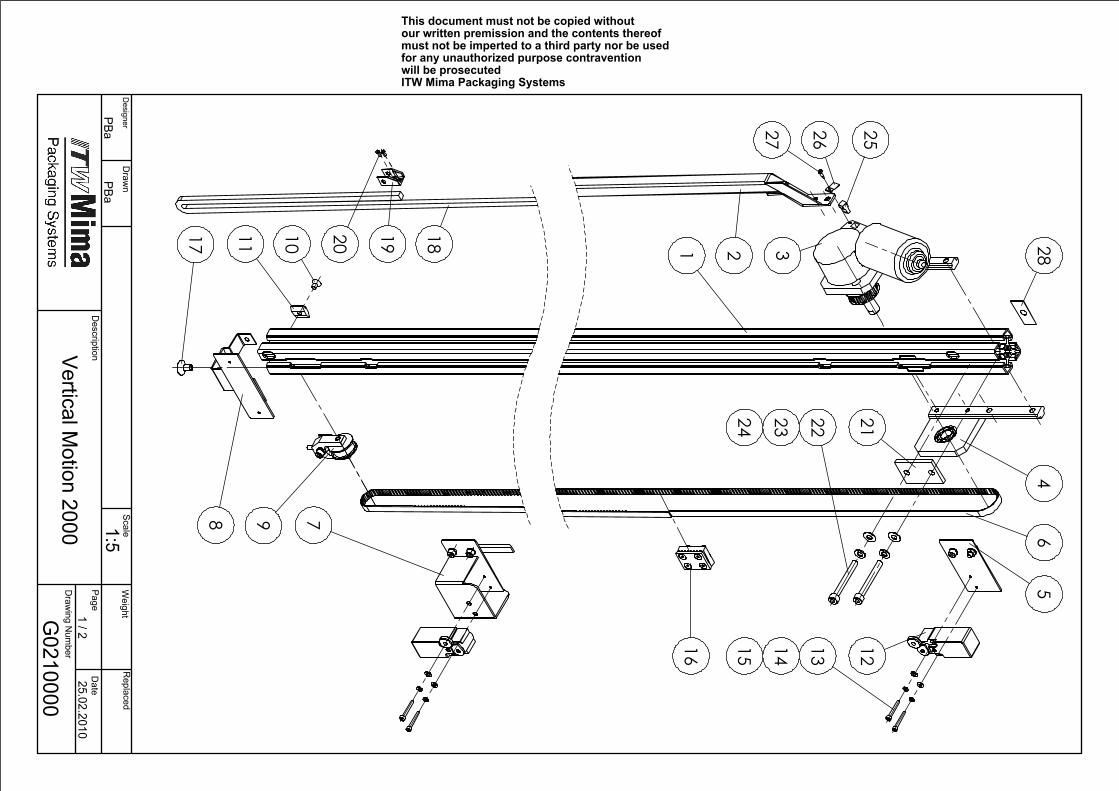
G0210000
25.02.2010Vertical M
otion 2000 1:51 / 2
PBaPBa
Weight
Designer
Draw
n Scale
Replaced
Description
Page D
ate
Draw
ing Num
ber
This document must not be copied without our written premission and the contents thereof must not be imperted to a third party nor be used for any unauthorized purpose contravention will be prosecutedITW Mima Packaging Systems
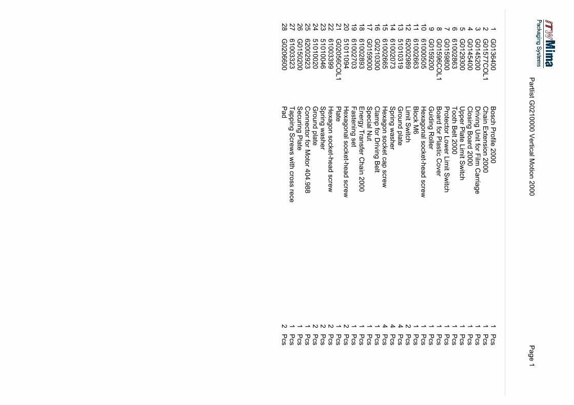
Partlis
t G0210000 Vertic
al M
otio
n 2000
Page 1
1G0136400
Bosch Profile
2000
1Pcs
2G01577COL1
Chain Extension 2000
1Pcs
3G0145200
Driv
ing Unit fo
r Film
Carria
ge
1Pcs
4G0145400
Closing Board 2000
1Pcs
5G0129300
Upper P
late Lim
it Switc
h1
Pcs
661002863
Tooth Belt 2
000
1Pcs
7G0159800
Protector L
ower L
imit S
witch
1Pcs
8G01596COL1
Board fo
r Plastic Cover
1Pcs
9G0159200
Guiding Rolle
r1
Pcs
10
61000505
Hexagonal socket-h
ead screw
1Pcs
11
61002663
Block M
61
Pcs
12
62002989
Lim
it Switch
2Pcs
13
51010319
Ground plate
4Pcs
14
61002073
Sprin
g washer
4Pcs
15
61002665
Hexagon socket c
ap screw
4Pcs
16
G0210300
Clamp fo
r Driv
ing Belt
1Pcs
17
G0159000
Special N
ut
1Pcs
18
61002893
Energy Transfer C
hain 2000
1Pcs
19
61002703
Fastening set
1Pcs
20
51011094
Hexagonal socket-h
ead screw
2Pcs
21
G02056COL1
Plate
1Pcs
22
61003399
Hexagon socket-h
ead screw
2Pcs
23
51010046
Sprin
g washer
2Pcs
24
51010020
Ground plate
2Pcs
25
62002923
Connector fo
r Motor 4
04.988
1Pcs
26
G0150200
Securin
g Plate
1Pcs
27
61003323
Tapping Screws with
cross re
ce
1Pcs
28
G0206600
Pad
2Pcs
��
��
���
�
�
�
�
��
����
�
�
�
�
�
���������������� �������� ������� �����
���������������� ��������������������
��������
�����������������
�� ���
������ ����� �� �
!�
�����"���������
�����
�#�$��%���&%���
��'%��$���
����"��'���� �(���)�
�*��
�!�
���������������������� ��
��������� ���������� ����� �������
������� ���� ������������ ���� ��� � ���
�������� ���� � �������������������� ��� ��
���������*��������
��������;
<=?FA<<;���&���;E
���;'��;,��#;$�������
����;=
=<=?FB<<
,����;:���/
=���
?<=?FF<<
���&���;:
���;+3���
=���
@<=?FD<<
)3�'�
=���
A<=?FC<<
,�4���;)3�'�
=���
BC?<<??=B
9�������;#
����=���
CB=<=D<=F
���&�;-���;-������
=���
DC=<<?CCA
)�����;)
��;)���2
=���
FC=<<?CC@
+�/��;0
��?���
>B=<=<<=D
����/;1����
C���
=<B=<=<D<>
��4������;������G3��/;����2
@���
==B=<=<<<>
��4������;����2
H;'���;�3���/�/=���
=?B=<=<?@B
��4������;����2
H'���;�3���/�/=���
=@B=<=<<@<
��4������;����2
H'���;�3���/�/=���

��
��
��
�
�
�
��
����
�
�
�
�
� �
�
����"
�*� �����������������
�� ����
�������
������ �������������������������
!��!�
����+���
�*�
��'���� �(���)�
���������������������� ��
����+���
�����"���������
�����
�#�$��%���&%���
��'%��$���
��������� ���������� ����� �������
������� ���� ������������ ���� ��� � ���
�������� ���� � �������������������� ��� ��
���������������� �������� ������� �����
������ ����� �� �
����������
��������;
<=AB?<<;���&���;E
���;'��;,��#;$�������
����;=
=<=?FB<<
,����;:���/
=���
?<=?FF<<
���&���;:
���;+3���
=���
@<=?FD<<
)3�'�
=���
A<=?FC<<
,�4���;)3�'�
=���
BC?<<??=B
9�������;#
����=���
CB=<=D<=F
���&�;-���;-������
=���
DC=<<?CAD
)�����;)
��;)���2
;$���;�
����=���
F<=AB=<<
��'�;���&�;$
�����=���
>B=<=<<=D
����/;1����
C���
=<B=<=<D<>
��4������;������G3��/;����2
@���
==B=<=<<<>
��4������;����2
H;'���;�3���/�/=���
=?B=<=<?@B
��4������;����2
H'���;�3���/�/=���
=@B=<=<<@<
��4������;����2
H'���;�3���/�/=���
3750
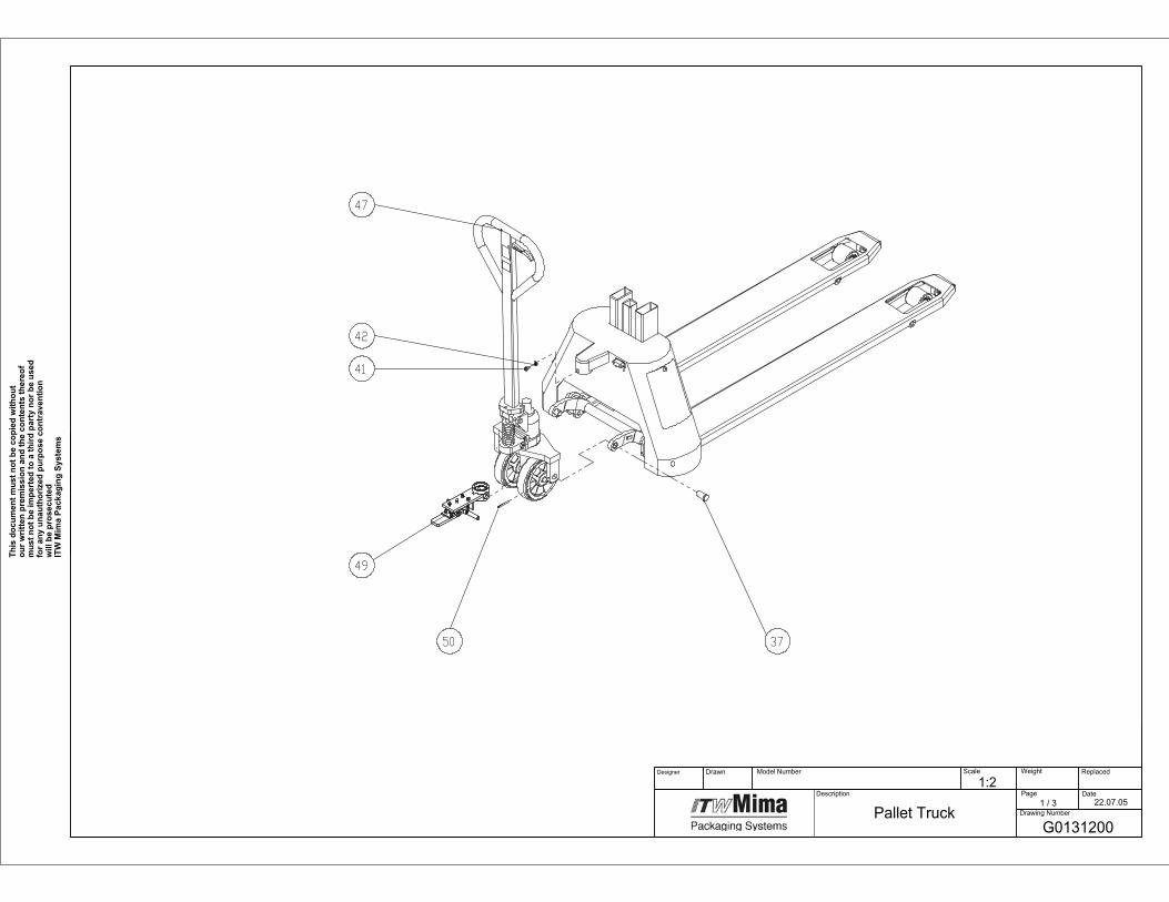
49
41
42
47
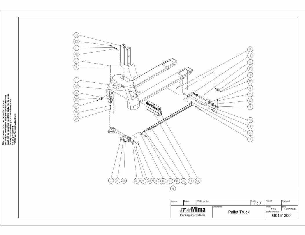
G0131200
22.07.05Pallet Truck
1:2 Model Number
Page1 / 3
Drawing Number
Date
Replaced Scale
Description
DrawnDesigner Weight
This
doc
umen
t mus
t not
be
copi
ed w
ithou
t ou
r writ
ten
prem
issi
on a
nd th
e co
nten
ts th
ereo
f m
ust n
ot b
e im
pert
ed to
a th
ird p
arty
nor
be
used
fo
r any
una
utho
rized
pur
pose
con
trav
entio
n w
ill b
e pr
osec
uted
ITW
Mim
a Pa
ckag
ing
Syst
ems
46
264518
30
15
19
27
28
29
21
25
22
20
23
18
24
17
43102591113147
39
38
32
31
36
40
1
3
37
42
34
35
33
44 48
G0131200
14.07.2006Pallet Truck
1:2.5 Model Number
Page2 / 3
Drawing Number
Date
Replaced Scale
Description
DrawnDesigner Weight
This
doc
umen
t mus
t not
be
copi
ed w
ithou
t ou
r writ
ten
prem
issi
on a
nd th
e co
nten
ts th
ereo
f m
ust n
ot b
e im
pert
ed to
a th
ird p
arty
nor
be
used
fo
r any
una
utho
rized
pur
pose
con
trav
entio
n w
ill b
e pr
osec
uted
ITW
Mim
a Pa
ckag
ing
Syst
ems
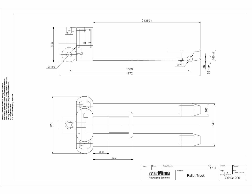
15091772
180
160m
in
55 m
ax35
1350
435
70
163
720
540
300
625
G0131200
22.03.2006
Pallet Truck
1:1.5 Model Number
Page3 / 3
Drawing Number
Date
Replaced Scale
Description
DrawnDesigner Weight
This
doc
umen
t mus
t not
be
copi
ed w
ithou
t ou
r writ
ten
prem
issi
on a
nd th
e co
nten
ts th
ereo
f m
ust n
ot b
e im
pert
ed to
a th
ird p
arty
nor
be
used
fo
r any
una
utho
rized
pur
pose
con
trav
entio
n w
ill b
e pr
osec
uted
ITW
Mim
a Pa
ckag
ing
Syst
ems
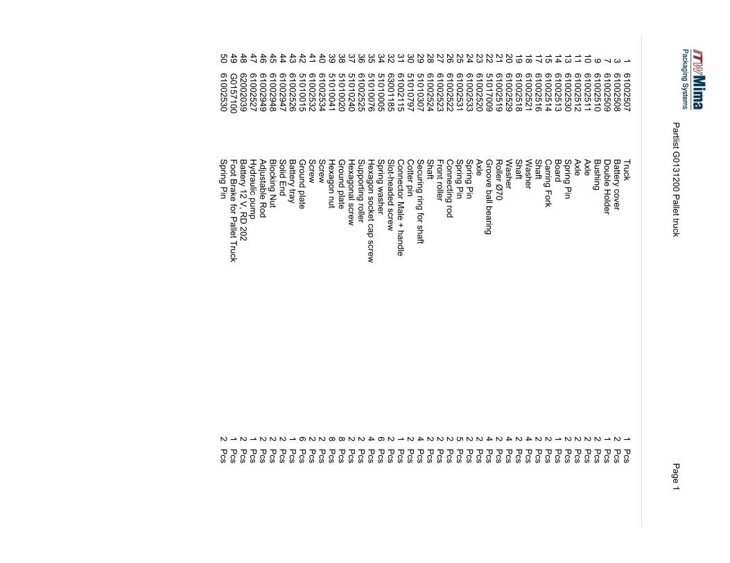
���������
� ���������������
������
������
���������
�����
:�����!���&��
����
�����(
���-����
��/������
(�����
:��3���
����
�������
"4��
����
��������
"4��
����
� ����
)1������
������
�������
:���/
����
��������
$�������,���
����
��������
)3�'�
����
��������
+��3��
����
�(������
)3�'�
����
������(
+��3��
����
�������(
�������K
�����
������(
���&��-����-������
����
� �����
"4��
����
������
)1������
������
������ �
)1������
������
��������
$������������/
����
�������
,���������������
��������
)3�'�
����
�(��� �
)�������������'����3�'�
����
����(�
$������1��
����
�������
$���������
����L�3��/������
�� ����
)���53��/�/�����2
����
�����
)1�����2
��3������
������
��4��������������1�����2
����
�������
)�11�������������
����
������
��4�����������2
����
�����
����/�1����
����
(�����
��4��������
����
����� �
)���2
����
������ �
)���2
����
�������
����/�1����
����
� ������
:�����!����!
����
�����(��
)���/�9
�/����
�����(��
:��������0
������
�����(�(
"/M����-����
�/����
��������
�!/�������1�#
1����
����� (
:�����!����.
7������
����
�(����
,����:�����'����
���������������
�����
)1������
������
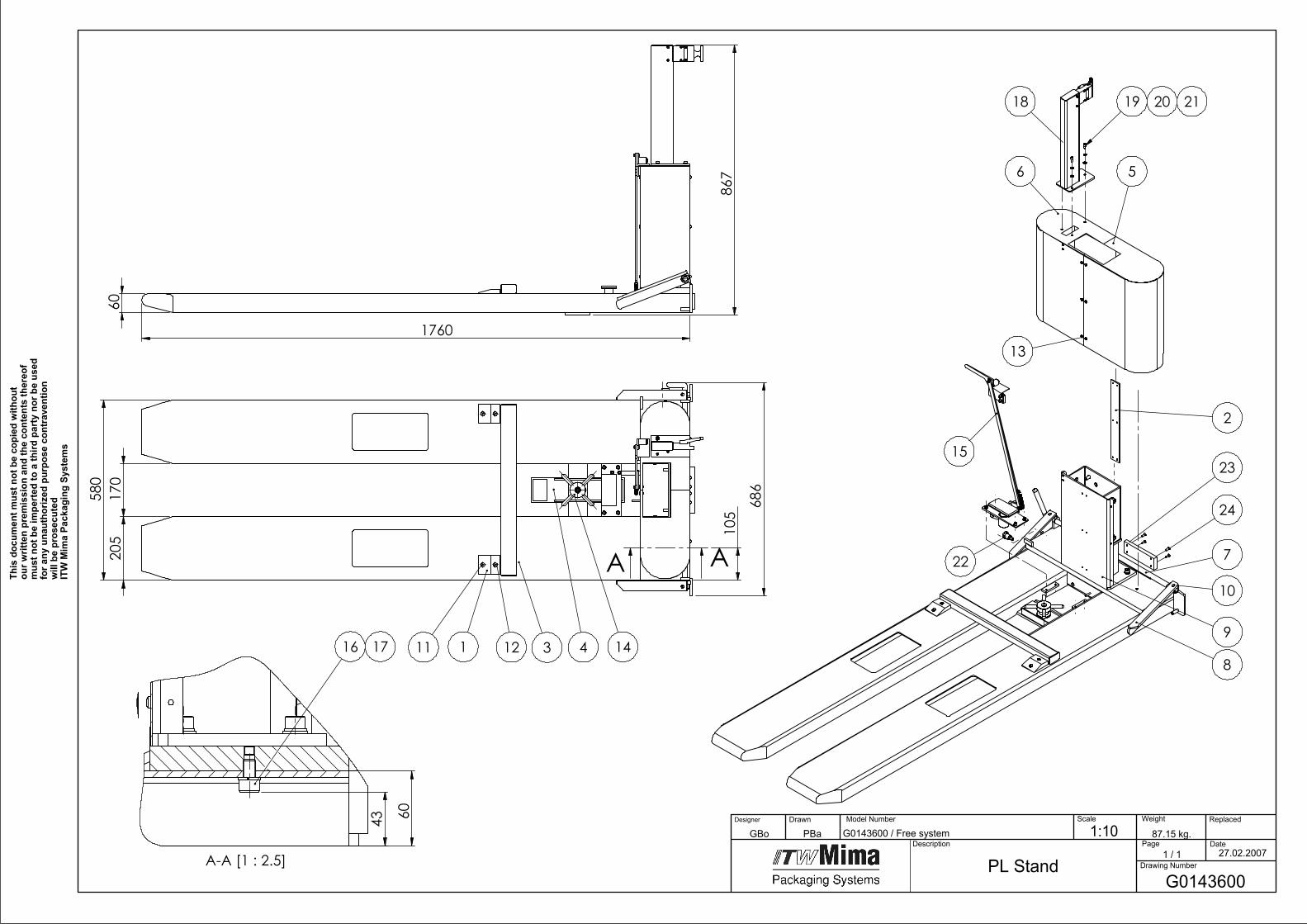
580
205
170
686
105
A A
1 3 411 12 14
1760
60
867
43 60
A-A [1 : 2.5]
16 17
2
7
8
9
10
15
13
6 5
22
19 20 2118
23
24
PL Stand
87.15 kg.
G0143600
1:10 Model Number
Page1 / 1
Drawing Number
Date
Replaced Scale
Description
DrawnDesigner
This
doc
umen
t mus
t not
be
copi
ed w
ithou
t ou
r writ
ten
prem
issi
on a
nd th
e co
nten
ts th
ereo
f m
ust n
ot b
e im
pert
ed to
a th
ird p
arty
nor
be
used
fo
r any
una
utho
rized
pur
pose
con
trav
entio
n w
ill b
e pr
osec
uted
ITW
Mim
a Pa
ckag
ing
Syst
ems
27.02.2007
Weight
G0143600 / Free systemPBaGBo

1G
01
33
10
0W
ed
ge2
Pcs
2G
01
32
7C
OL1
Rib
1P
cs
3G
01
43
7C
OL1
PL B
ase Fram
e1
Pcs
4G
02
00
2C
OL1
Sup
po
rd B
oard
1P
cs
5G
02
29
1C
OL1
Righ
t Co
ver PL
1P
cs
6G
02
29
0C
OL1
Left Co
ver PL
1P
cs
7G
01
32
4C
OL1
Lon
g Arm
1P
cs
8G
01
32
3C
OL1
Arm
1P
cs
9G
01
32
80
0Stan
d - Set
1P
cs
10
51
01
03
84
Pin
1P
cs
11
51
01
01
42
Screw2
Pcs
12
51
01
04
56
Screw2
Pcs
13
61
00
25
34
Screw1
6P
cs
14
G0
20
01
00
01
Kn
ob
1P
cs
15
G0
14
48
00
Fixing M
echan
ism1
Pcs
16
51
01
00
05
Sprin
g Wash
er2
Pcs
17
51
01
00
81
Wash
er2
Pcs
18
G0
22
47
00
Extensio
n Set
1P
cs
19
51
01
00
49
Screw3
Pcs
20
51
01
00
13
Sprin
g Wash
er3
Pcs
21
51
01
00
17
Wash
er3
Pcs
22
61
00
24
37
Bu
shin
g1
Pcs
23
G0
21
87
00
Bu
ffer1
Pcs
24
51
01
05
34
Hexago
nal so
cket-h
ead screw
4P
cs
Partlist G
01
43
60
0 P
L Stand
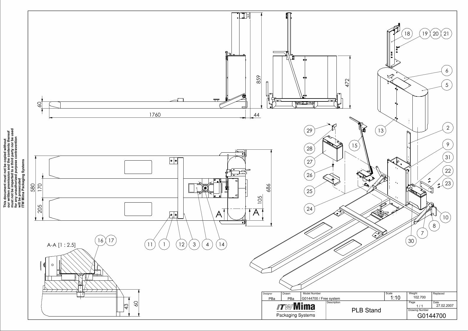
580
205
170
686
105
A A
1 3 411 12 14
1760
60
859
44
472
43 60
A-A [1 : 2.5]16 17
2
78
9
10
15
13
6
5
18
24
25
26
27
28
29
30
31
22
23
19 20 21
PLB StandG0144700
1:10 102.700 Page
1 / 1 Drawing Number
Date
Replaced Scale
Description
DrawnDesigner
This
doc
umen
t mus
t not
be
copi
ed w
ithou
t ou
r writ
ten
prem
issi
on a
nd th
e co
nten
ts th
ereo
f m
ust n
ot b
e im
pert
ed to
a th
ird p
arty
nor
be
used
fo
r any
una
utho
rized
pur
pose
con
trav
entio
n w
ill b
e pr
osec
uted
ITW
Mim
a Pa
ckag
ing
Syst
ems
27.02.2007
Weight
G0144700 / Free systemPBaPBa Model Number

1G
01
33
10
0W
ed
ge2
Pcs
2G
01
32
7C
OL1
Rib
1P
cs
3G
01
43
7C
OL1
PL B
ase Fram
e1
Pcs
4G
02
00
2C
OL1
Sup
po
rt Bo
ard1
Pcs
5G
02
29
1C
OL1
Righ
t Co
ver PL
1P
cs
6G
02
29
0C
OL1
Left Co
ver PL
1P
cs
7G
01
32
4C
OL1
Lon
g Arm
1P
cs
8G
01
32
3C
OL1
Arm
1P
cs
9G
01
32
80
0Stan
d - Set
1P
cs
10
51
01
03
84
Pin
1P
cs
11
51
01
01
42
Screw2
Pcs
12
51
01
04
56
Screw2
Pcs
13
61
00
25
34
Screw1
6P
cs
14
G0
20
01
00
01
Kn
ob
1P
cs
15
G0
14
48
00
Fixing M
echan
ism1
Pcs
16
51
01
00
05
Sprin
g Wash
er2
Pcs
17
51
01
00
81
Screw2
Pcs
18
G0
22
47
00
Extensio
n Set
1P
cs
19
51
01
00
49
Screw3
Pcs
20
51
01
00
13
Sprin
g Wash
er3
Pcs
21
51
01
00
17
Wash
er3
Pcs
22
G0
21
87
00
Bu
ffer1
Pcs
23
51
01
05
34
Hexago
nal so
cket-h
ead screw
4P
cs
24
61
00
24
37
Bu
shin
g1
Pcs
25
G0
15
39
CO
L1R
ight C
asette fo
r Battery
1P
cs
26
51
01
05
94
Hexago
nal so
cket-h
ead screw
2P
cs
27
62
00
29
91
Batte
ry Set for P
LB1
Pcs
28
G0
15
35
CO
L1Left P
late PLB
1P
cs
29
61
00
25
34
Screw2
Pcs
30
G0
15
36
CO
L1R
ight P
late PLB
1P
cs
31
G0
15
38
CO
L1Left C
asette fo
r Battery
1P
cs
Partlist G
01
44
70
0 P
LB Stan
d
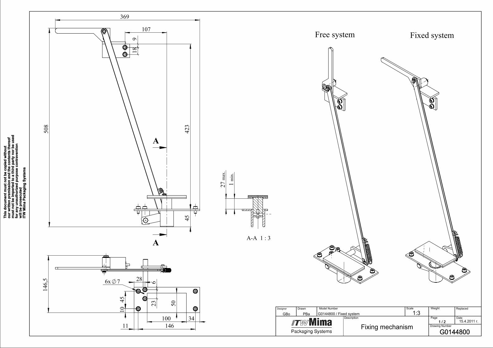
508
369
18
4542
3
9
107
A
A
Fixed system
27m
ax.
1m
in.
A-A 1 : 3
100
50
146
45
23
10
6
11
6x 7
146,
5 28
34
Free system
G0144800 / Fixed system
G0144800
15.4.2011 г.
Fixing mechanism
PBaGBo
1 / 2
This
doc
umen
t mus
t not
be
copi
ed w
ithou
t ou
r writ
ten
prem
issi
on a
nd th
e co
nten
ts th
ereo
f m
ust n
ot b
e im
pert
ed to
a th
ird p
arty
nor
be
used
fo
r any
una
utho
rized
pur
pose
con
trav
entio
n w
ill b
e pr
osec
uted
ITW
Mim
a Pa
ckag
ing
Syst
ems
G0144800
1:3 Model Number
Page1 / 2
Drawing Number
Date
Replaced Scale
Description
DrawnDesigner Weight
This
doc
umen
t mus
t not
be
copi
ed w
ithou
t ou
r writ
ten
prem
issi
on a
nd th
e co
nten
ts th
ereo
f m
ust n
ot b
e im
pert
ed to
a th
ird p
arty
nor
be
used
fo
r any
una
utho
rized
pur
pose
con
trav
entio
n w
ill b
e pr
osec
uted
ITW
Mim
a Pa
ckag
ing
Syst
ems
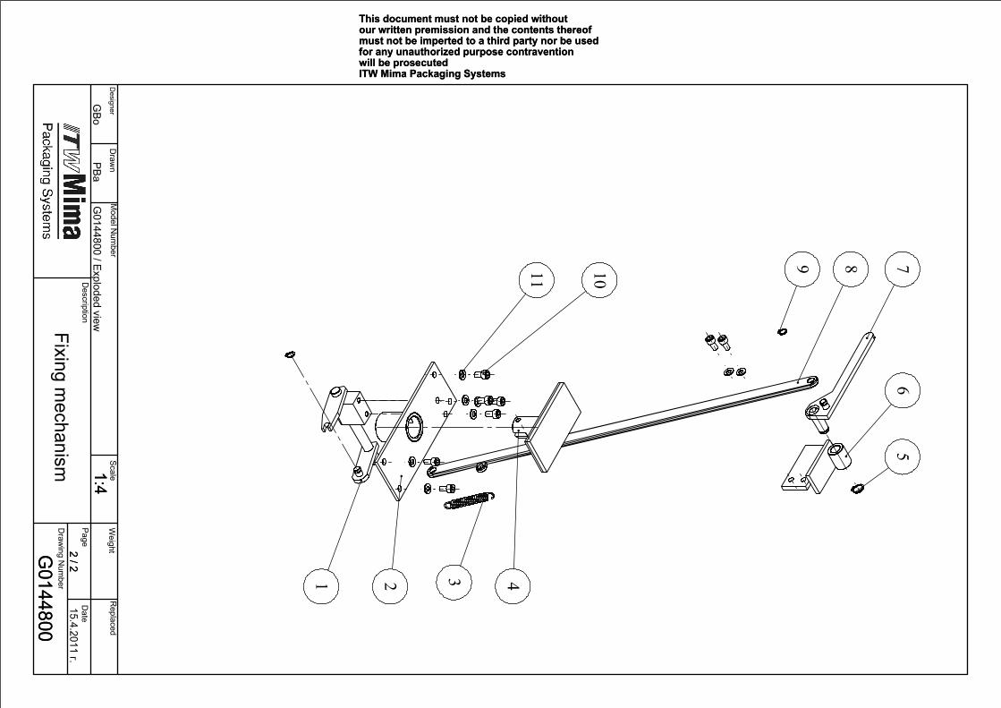
2 4
8
67
5
10
31
11
9
G0144800
15.4.2011 г.
1:42 / 2
G0144800 / Exploded view
PBaG
Bo
This document must not be copied without our written premission and the contents thereof must not be imperted to a third party nor be used for any unauthorized purpose contravention will be prosecutedITW Mima Packaging Systems
Fixing mechanism
G0144800
1:42 / 2
Weight
Designer
Draw
n Scale
Replaced
Description
Page D
ate
Draw
ing Num
ber
This document must not be copied without our written premission and the contents thereof must not be imperted to a third party nor be used for any unauthorized purpose contravention will be prosecutedITW Mima Packaging Systems
Model N
umber

1G
02
06
10
00
1C
arrier1
Pcs
2G
01
38
10
0B
ase Plate
1P
cs
3G
01
52
40
00
1Sp
ring
1P
cs
4G
01
43
80
0B
otto
m H
eel1
Pcs
55
10
10
11
6Secu
ring rin
g for sh
aft1
Pcs
6G
01
38
20
0Su
pp
ort - 1
1P
cs
7G
01
38
00
0Lever
1P
cs
8G
01
44
50
0R
od
1P
cs
95
10
10
30
7Secu
ring rin
g for sh
aft2
Pcs
10
51
01
00
49
Screw8
Pcs
11
51
01
00
13
Sprin
g Wash
er8
Pcs
Partlist G
01
44
80
0 Fixin
g Mech
anism
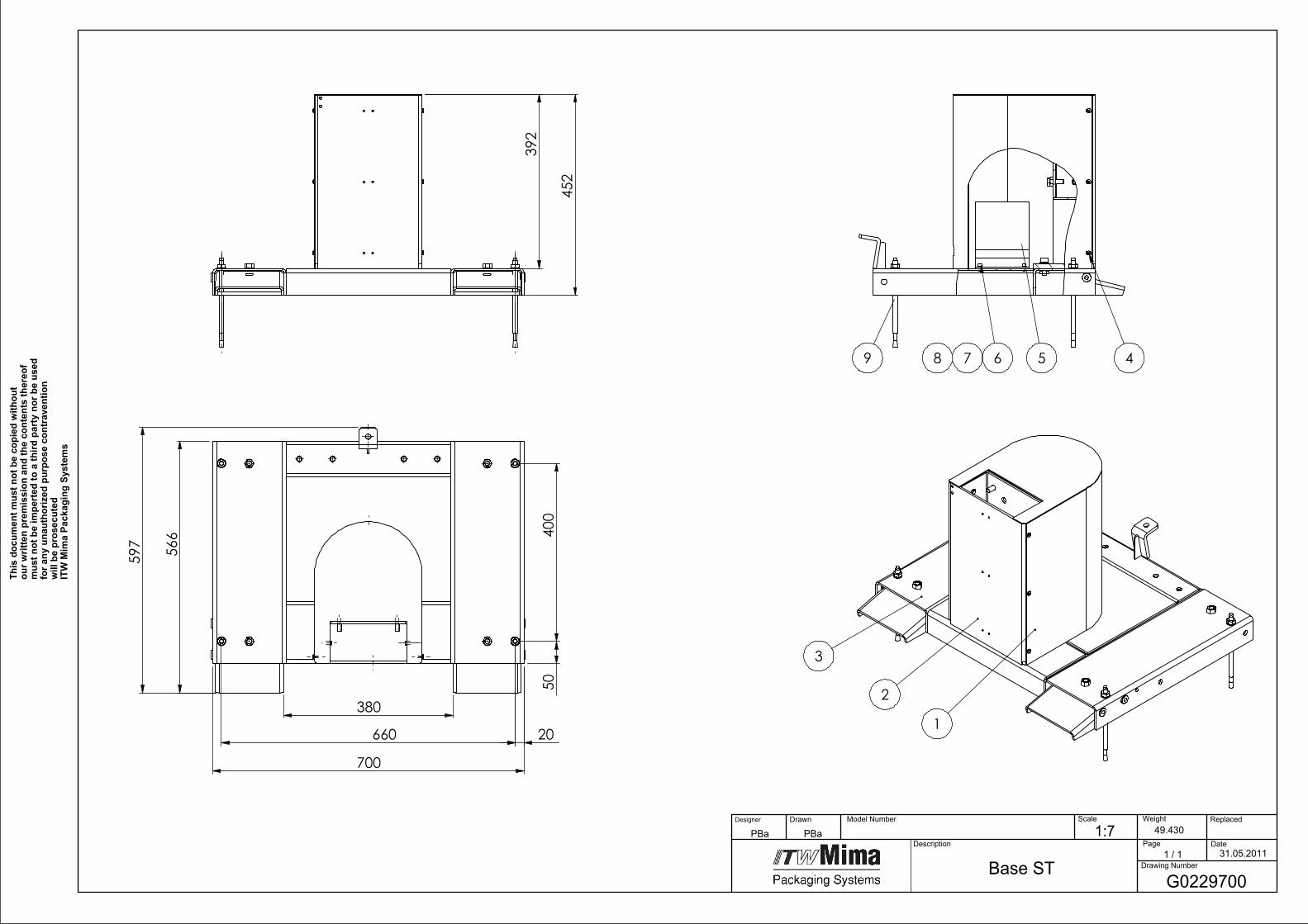
700
380
597
50400
20660
566
2
3
1
452
392
5 49 678
Base STG0229700
31.05.2011
1:7PBaPBa 49.430 Model Number
Page1 / 1
Drawing Number
Date
Replaced Scale
Description
DrawnDesigner Weight
This
doc
umen
t mus
t not
be
copi
ed w
ithou
t ou
r writ
ten
prem
issi
on a
nd th
e co
nten
ts th
ereo
f m
ust n
ot b
e im
pert
ed to
a th
ird p
arty
nor
be
used
fo
r any
una
utho
rized
pur
pose
con
trav
entio
n w
ill b
e pr
osec
uted
ITW
Mim
a Pa
ckag
ing
Syst
ems

1G
01
33
3C
OL1
Co
ver ST1
Pcs
2G
01
32
80
0Stan
d - Set
1P
cs
3G
02
29
5C
OL1
Frame ST/STB
1P
cs
46
10
02
53
4Screw
6P
cs
56
20
03
48
4P
ow
er Su
pp
ly Un
it1
Pcs
65
10
10
62
6H
exagon
al socke
t-head
screw4
Pcs
75
10
10
91
9Sp
ring W
asher
4P
cs
85
10
10
11
0W
asher
4P
cs
96
10
03
46
6A
nch
or B
olt
4P
cs
Partlist G
02
29
70
0 B
ase ST
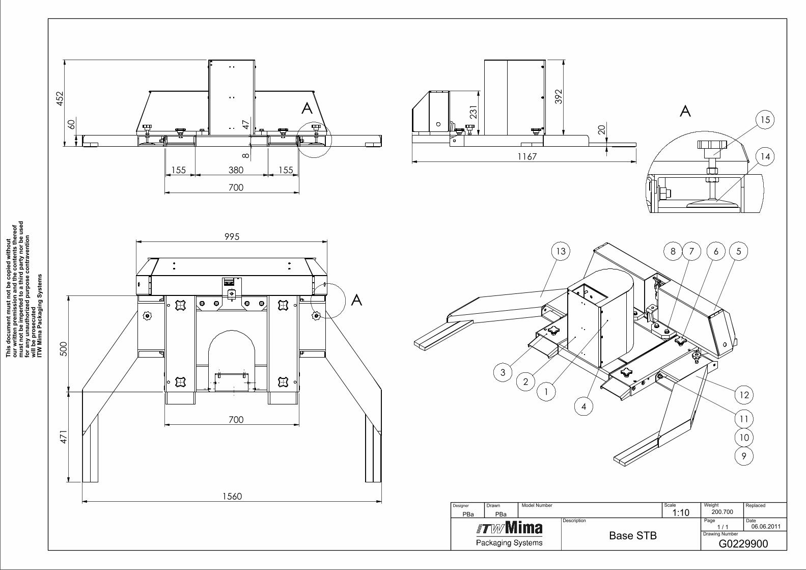
1560
471
500
995
700
A
4
23
1
578 6
11
10
9
12
13
452
60
380155 155
700
847
A 231
20
392
1167 14
15A
Base STBG0229900
06.06.2011
1:10PBaPBa 200.700 Model Number
Page1 / 1
Drawing Number
Date
Replaced Scale
Description
DrawnDesigner Weight
This
doc
umen
t mus
t not
be
copi
ed w
ithou
t ou
r writ
ten
prem
issi
on a
nd th
e co
nten
ts th
ereo
f m
ust n
ot b
e im
pert
ed to
a th
ird p
arty
nor
be
used
fo
r any
una
utho
rized
pur
pose
con
trav
entio
n w
ill b
e pr
osec
uted
ITW
Mim
a Pa
ckag
ing
Syst
ems

1G
01
33
3C
OL1
Co
ver ST1
Pcs
2G
01
32
80
0Stan
d - Set
1P
cs
3G
02
29
5C
OL1
Frame ST/STB
1P
cs
46
10
02
53
4Screw
6P
cs
5G
02
30
00
0P
ow
er B
ox
1P
cs
66
10
02
86
8G
rip w
ith M
12
*40
screw4
Pcs
75
10
10
02
8Screw
4P
cs
85
10
10
02
2W
asher
4P
cs
95
10
10
25
4Screw
4P
cs
10
51
01
00
22
Wash
er4
Pcs
11
51
01
00
39
Nu
t4
Pcs
12
G0
23
02
CO
L1R
ight Stab
ilizer1
Pcs
13
G0
23
03
CO
L1Left Stab
ilizer1
Pcs
14
61
00
37
57
Align
men
t Leg2
Pcs
15
61
00
26
57
Han
dle
2P
cs
Partlist G
02
29
90
0 B
ase STB
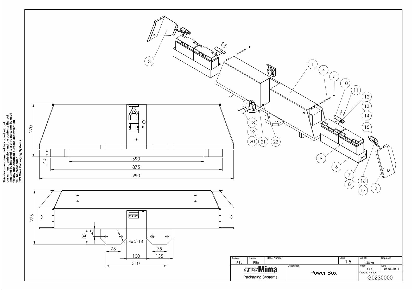
990
40
270
875
690
310
754x 14
40
75100 135
80
276
1
2
3
45
6
9
1011
12
13
1418
19
20
15
21 22
7
8 16
17
G0230000
06.06.2011Power Box
128 kg1:5PBaPBa Model Number
Page1 / 1
Drawing Number
Date
Replaced Scale
Description
DrawnDesigner Weight
This
doc
umen
t mus
t not
be
copi
ed w
ithou
t ou
r writ
ten
prem
issi
on a
nd th
e co
nten
ts th
ereo
f m
ust n
ot b
e im
pert
ed to
a th
ird p
arty
nor
be
used
fo
r any
una
utho
rized
pur
pose
con
trav
entio
n w
ill b
e pr
osec
uted
ITW
Mim
a Pa
ckag
ing
Syst
ems
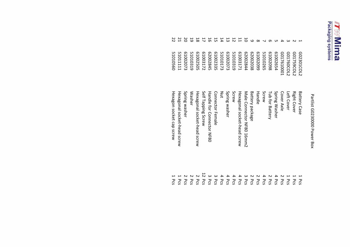
1G
02
30
1C
OL2
Batte
ry Case
1P
cs
2G
01
75
9C
OL2
Righ
t Co
ver1
Pcs
3G
01
76
0C
OL2
Left Co
ver1
Pcs
4G
01
76
10
00
1C
over A
xle2
Pcs
56
10
02
65
4Sp
ring W
asher
4P
cs
66
10
02
09
8Tu
b fo
r Battery
2P
cs
75
10
10
26
5Screw
4P
cs
86
10
02
09
9H
and
le2
Pcs
96
20
02
03
8B
attery p
ackage2
Pcs
10
62
00
28
44
Male C
on
necto
r NF8
0 1
6m
m2
3P
cs
11
61
00
31
71
Hexago
nal so
cket-h
ead screw
4P
cs
12
51
01
03
19
Screw4
Pcs
13
61
00
20
73
Sprin
g wash
er4
Pcs
14
51
01
01
73
Nu
t4
Pcs
15
61
00
23
35
Co
nn
ector Fem
ale3
Pcs
16
62
00
28
45
Han
dle fo
r Co
nn
ector N
F80
3P
cs
17
61
00
31
72
Self Tapp
ing Screw
12
Pcs
18
61
00
25
05
Hexago
nal so
cket-h
ead screw
2P
cs
19
51
01
03
19
Wash
er2
Pcs
20
61
00
20
73
Sprin
g wash
er2
Pcs
21
51
01
11
11
Hexago
nal so
cket-h
ead screw
1P
cs
22
51
01
05
60
Hexago
n so
cket cap
screw1
Pcs
Partlist G
02
30
00
0 P
ow
er B
ox
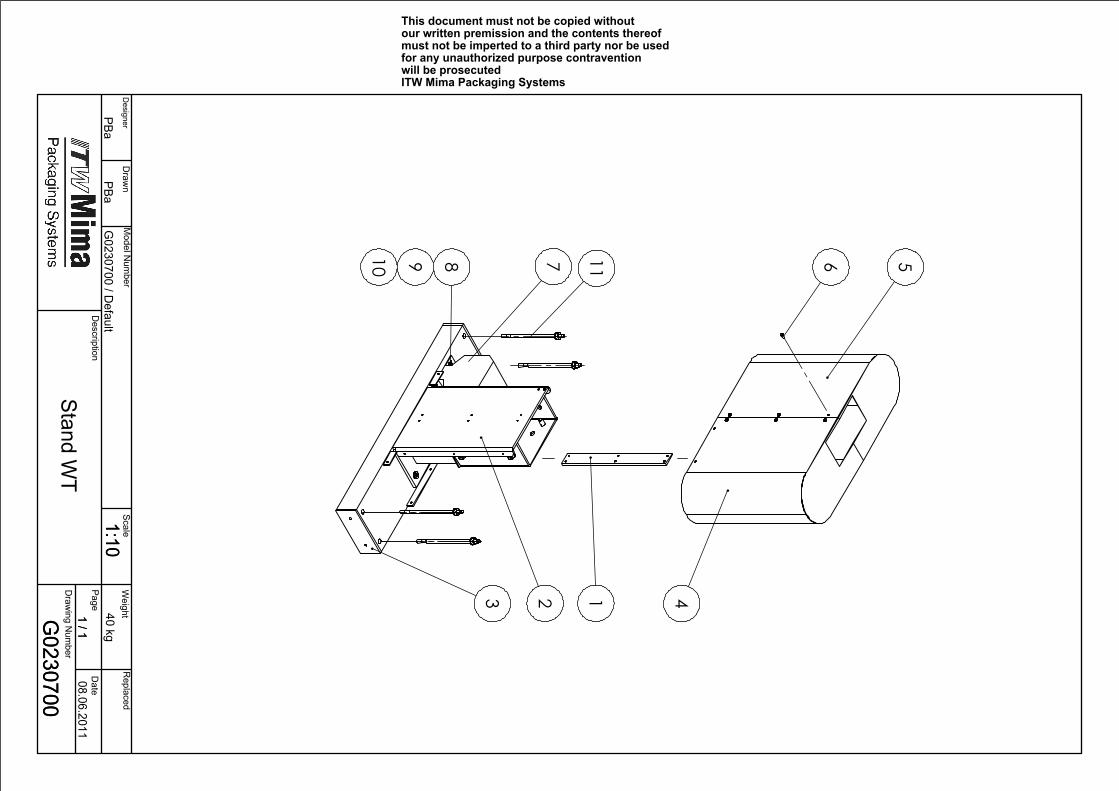
3 2 1 4
6 578910 11
G0230700
08.06.2011Stand W
T
1:101 / 1
G0230700 / D
efaultPBa
PBa
G0230700
1:101 / 1
40 kg W
eightD
esigner D
rawn
ScaleR
eplaced
Description
Page D
ate
Draw
ing Num
ber
This document must not be copied without our written premission and the contents thereof must not be imperted to a third party nor be used for any unauthorized purpose contravention will be prosecutedITW Mima Packaging Systems
Model N
umber

1G
01
32
7C
OL1
Rib
1P
cs
2G
01
32
80
0Stan
d - Set
1P
cs
3G
01
33
8C
OL1
Base
1P
cs
4G
02
06
5C
OL1
Righ
t Co
ver1
Pcs
5G
01
34
5C
OL1
Left Co
ver1
Pcs
66
10
02
53
4Screw
16
Pcs
76
20
02
56
6Tran
sform
er1
Pcs
85
10
10
62
6H
exagon
al socke
t-head
screw4
Pcs
95
10
10
91
9Sp
ring W
asher
4P
cs
10
51
01
01
10
Wash
er4
Pcs
11
61
00
34
66
An
cho
r Bo
lt4
Pcs
Partlist G
02
30
70
0 Stan
d W
T
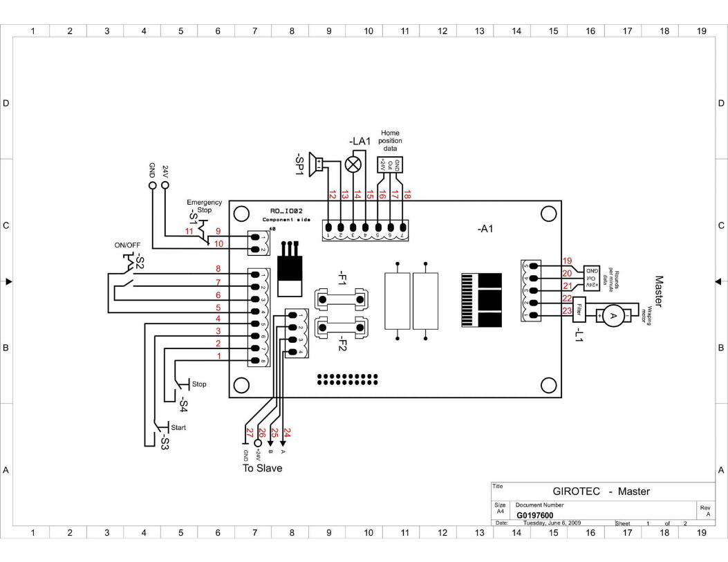
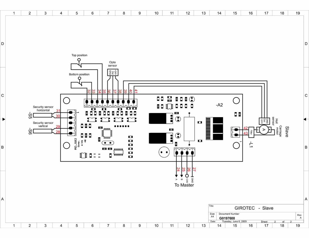

01
A1
62
00
35
36
MA
STER M
od
ule
1P
cs
02
A2
62
00
20
91
SLAV
E mo
du
le1
Pcs
01
S16
20
03
08
4Em
ergency Sto
p w
ith K
ey1
Pcs
01
S26
20
02
08
5Sw
itch 2
-po
s / com
plete
1P
cs
01
S36
20
02
08
2P
ush
bu
tton
Gree
n / C
om
plete
1P
cs
01
S46
20
02
08
3P
ush
bu
tton
red
/ com
plete
1P
cs
61
00
22
38
Co
ntro
l pan
el plate
(Alu
min
ium
)1
Pcs
01
F16
20
02
38
7G
lass tub
e fuse
1P
cs
01
F26
20
02
14
5G
lass tub
e fuse
1P
cs
Partlist G
01
97
70
0 Electrical C
om
po
nen
ts Giro
tec

���������
�� ��������������
����������
������������
��
������������
����������
�������
���
����
���������1��
����
� ������
2����0�������0������
���
� ������
2����0�������0������
���