Embed Size (px)
Citation preview

IT 12 053
Examensarbete 30 hpOktober 2012
Service Discovery for IP-based Wireless Sensor Networks
Martin Russo
Institutionen för informationsteknologiDepartment of Information Technology


Teknisk- naturvetenskaplig fakultet UTH-enheten Besöksadress: Ångströmlaboratoriet Lägerhyddsvägen 1 Hus 4, Plan 0 Postadress: Box 536 751 21 Uppsala Telefon: 018 – 471 30 03 Telefax: 018 – 471 30 00 Hemsida: http://www.teknat.uu.se/student
Abstract
Service Discovery for IP-based Wireless SensorNetworks
Martin Russo
In a Wireless Sensor Network (WSN), the services that each sensor node canprovide must be described according to a standard and possible to discover by otherdevices.Protocols such as the well established UPnP (Universal Plug and Play) aim atfacilitating the advertisement and discovery of network services and already exist inmany computer networks. We suggest to use UPnP for WSNs.Designing protocols for WSNs, engineers often face battery, memory andcomputation constraints, which impose proper evaluations to be conducted and whennecessary, reasonable trade-offs to be adopted.The goal of this thesis project is to allow the sensor nodes to announce, discover anduse services with UPnP and study the efficiency of the solutions put in place in thecontext of low-power embedded networks. Finally, optimizations to the protocol are proposed to render it more lightweight.Among other results, the power consumption of the radio and the latency of ServiceDiscovery are reduced by 20% and over 60% respectively.
Tryckt av: Reprocentralen ITC
Sponsor: SICS, Yanzi NetworksIT 12 053Examinator: Philipp RümmerÄmnesgranskare: Thiemo VoigtHandledare: Joakim Eriksson

i
Acknowledgements
I would like to thank my supervisor, Joakim Eriksson, for helping me define the thesisand providing constant support while the project was carried out.I also want to thank my reviewer, Thiemo Voigt, whose worthy comments allowed meto improve the report.I am also very grateful to everyone else at SICS (Swedish Institute of Computer Sci-ence) who has provided me with advices when dealing with the project’s challenges.Finally, an acknowledgement goes to Yanzi Networks, who provided the first UPnPsource code that was later developed in this project.
ii

iii

Contents
1 Introduction 11.1 Wireless sensor networks . . . . . . . . . . . . . . . . . . . . . . . . 11.2 Service discovery . . . . . . . . . . . . . . . . . . . . . . . . . . . . 21.3 Approach . . . . . . . . . . . . . . . . . . . . . . . . . . . . . . . . 21.4 Results . . . . . . . . . . . . . . . . . . . . . . . . . . . . . . . . . . 31.5 Document structure . . . . . . . . . . . . . . . . . . . . . . . . . . . 3
2 Background 42.1 Contiki and protocol stack . . . . . . . . . . . . . . . . . . . . . . . 42.2 Cooja: a wireless sensor network simulator . . . . . . . . . . . . . . 62.3 Hardware platforms for Contiki . . . . . . . . . . . . . . . . . . . . . 7
2.3.1 Tmote Sky . . . . . . . . . . . . . . . . . . . . . . . . . . . 72.3.2 Wismote . . . . . . . . . . . . . . . . . . . . . . . . . . . . 8
2.4 Service Discovery . . . . . . . . . . . . . . . . . . . . . . . . . . . . 82.4.1 UPnP . . . . . . . . . . . . . . . . . . . . . . . . . . . . . . 82.4.2 mDNS . . . . . . . . . . . . . . . . . . . . . . . . . . . . . 11
2.5 Related work . . . . . . . . . . . . . . . . . . . . . . . . . . . . . . 112.5.1 Service Discovery in Wireless Sensor Networks . . . . . . . . 112.5.2 CoAP . . . . . . . . . . . . . . . . . . . . . . . . . . . . . . 12
3 Design and implementation 133.1 System architecture . . . . . . . . . . . . . . . . . . . . . . . . . . . 133.2 Implementation . . . . . . . . . . . . . . . . . . . . . . . . . . . . . 16
3.2.1 UPnP in Contiki . . . . . . . . . . . . . . . . . . . . . . . . 163.2.2 Development toolchain and UPnP IPv6 client . . . . . . . . . 16
4 Evaluation 214.1 Experiments on hardware platforms . . . . . . . . . . . . . . . . . . 214.2 Energy consumption and latency evaluation . . . . . . . . . . . . . . 214.3 Optimizations to UPnP in Contiki . . . . . . . . . . . . . . . . . . . 234.4 Discussion . . . . . . . . . . . . . . . . . . . . . . . . . . . . . . . . 25
5 Conclusions and Future work 30
iv
List of Figures
2.1 Contiki protocol stack . . . . . . . . . . . . . . . . . . . . . . . . . . 52.2 Cooja Simulator . . . . . . . . . . . . . . . . . . . . . . . . . . . . . 72.3 Tmote Sky . . . . . . . . . . . . . . . . . . . . . . . . . . . . . . . . 82.4 Wismote . . . . . . . . . . . . . . . . . . . . . . . . . . . . . . . . . 8
3.1 UPnP in the protocol stack . . . . . . . . . . . . . . . . . . . . . . . 143.2 System architecture . . . . . . . . . . . . . . . . . . . . . . . . . . . 153.3 UPnP transaction diagram . . . . . . . . . . . . . . . . . . . . . . . 173.4 Simulation architecture . . . . . . . . . . . . . . . . . . . . . . . . . 193.5 UPnP IPv6 client . . . . . . . . . . . . . . . . . . . . . . . . . . . . 20
4.1 Experiment setup . . . . . . . . . . . . . . . . . . . . . . . . . . . . 224.2 Impact of radio duty-cycling on latency . . . . . . . . . . . . . . . . 244.3 Duty-cycle comparison . . . . . . . . . . . . . . . . . . . . . . . . . 264.4 Average latency of one update message comparison . . . . . . . . . . 274.5 Latency reduction with Service Caching . . . . . . . . . . . . . . . . 28
1 Poster for SICS Open House on 26 April, 2012 . . . . . . . . . . . . 34
v

Chapter 1
Introduction
In this chapter some general concepts regarding the technologies involved in the projectand its motivations are introduced.The problem of service discovery in wireless sensor network is formulated, followedby the approach to solve it.
1.1 Wireless sensor networksA Wireless Sensor Network (WSN) is a set of autonomous nodes distributed across aarea and configured to form a network. Each node of the network, commonly referredas sensor node, is normally a tiny embedded device which typically consists of severalcomponents: a microcontroller, a radio transceiver, sensors (and possibly actuators)and a battery supply.Each node has the ability to sense the environment and send (either directly or throughother nodes) the data to a sink node which will store the sensed information, which caneasily be retrieved or even made accessible from the Internet. The software embeddedin the nodes is a small operating system whose main tasks are implementing the net-work protocols stack, interfacing to the sensors and regulating the low power modes.Nowadays WSNs are already a well-known solution in applications areas which in-clude environmental monitoring, military surveillance, medical care, smart grid, struc-tural monitoring, the Internet of things and so forth [1].In environmental monitoring, the sensors can measures physical quantities like light,motion, temperature, humidity, sound etc., collect this information and send it to a sink,which might send a notification over the Internet in case some values go beyond a cer-tain threshold [2].Sensor networks are used in medical care as well to monitor patients’ health [3]. Pa-tients wear sensors that measure e.g. blood pressure, blood oxygen, saturation heartrate, and this information can be displayed on medical machineries as well as on nursesand doctors’ client devices(PCs, smartphones etc.). In this case, patients’ mobility isalso improved thanks to wireless technology.Internet of things is about having smart and mainly wireless devices connected to the
1

Internet. These devices will be able to communicate the information they sense fromthe physical world and retrieve useful data from the Internet as well. Human users ofthe Internet are predicted to be a small minority in a few years [4].In general, sensor nodes might be equipped with any kind of sensor depending on theapplication: mechanical, thermal, biological, chemical, optical, and magnetic sensorsare only some examples. Regardless of their hardware, the protocols through whichthey communicate are lightweight implementations of the ones used in general pur-pose computer networks, such as the protocols of the TCP/IP stack.Since a WSN might consist in dozens (or even hundreds and upwards) of battery oper-ated sensor nodes, possibly deployed in remote or inconvenient environments, chang-ing run-down batteries is often impractical or economically infeasible. It is thereforecrucial to find mechanisms to reduce power consumption and prolong the network’sbattery life time. It is well known that the most energy consuming component is theradio, with its listening, transmitting and receiving operations. The radio must be there-fore turned off for most of the time, and only periodically turned on to transmit dataor to detect transmission attempts by other nodes. This mechanism is called radioduty-cycling, and has been the focus of attentive research aimed at minimizing energyconsumption while still keeping acceptable levels of communication capability in thenetwork. In some cases, the nodes may also rely on solar cells to harvest energy fromthe environment [5].
1.2 Service discoveryGiven a WSN, in order to find out what services are provided by the nodes, a protocolis needed to define how the communication for discovery and usage has to take place.The two main categories of service we can identify in WSNs are reading sensors’ val-ues or controlling an actuator. The aim of service discovery protocols is to facilitatethe detection and the announcement of network services within a local network.
SD discovery protocols can be firstly categorized as centralized and distributed [6].Centralized protocols rely on the presence of one entity in the network (normally aserver) where the nodes register their services and the clients search for them.
In distributed protocols, each node is assumed to be responsible for conveying itsown capabilities upon every client’s query, thus the communication between serviceprovider and user occurs in a peer-to-peer fashion. Examples of distributed servicediscovery protocols are UPnP, used by millions of local network devices as well asTV-sets and mDNS-SD, which is primarily used by Apple’s Bonjour.
1.3 ApproachGiven the presence of little or no infrastructure in a typical WSN, we decided to optfor a distributed SD protocol like UPnP.The UPnP standard defines functionalities such as service discovery, control, event no-
2

tification etc. that are typically utilized in Local Area Networks in order for networkdevices like personal computers, routers, to automatically discover other’s presence onthe network and establish working communication configuration[7].Each node in WSN must be able to answer to multicast requests and convey its capa-bilities, as well as storing locally the standard-defined descriptions for its services.After retrieving the description for a given service, a client knows the interface to thatservice and can start to use it.
1.4 ResultsIn this project the facilities of the UPnP protocol for service discovery and controlhave been implemented and evaluated in Contiki, an operating system for wireless sen-sor networks. The technologies employed in the project are IPv6 over 802.15.4 (with6LowPAN header compression) and RPL.We show that it is possible to run UPnP on sensor node platform such as Wismote,and we evaluate the implementation with regard to energy consumption and latency ofresponse.Moreover, some simplifications are proposed in order to render the protocol morelightweight. Compared to the original version, the power consumption of the radioand the Service Discovery latency are reduced by 20% and over 60% respectively.The use case is a sensor node that can announce and offer the services of reading tem-perature and switching on and off its LEDs.Furthermore, a UPnP IPv6 client has been developed in Java. It runs on the PC sideand its purpose is to test the features developed on the sensor node side, and to have acomplete development toolchain.
1.5 Document structureThis document is structured as follows. Chapter 1 contains introduction to the problemand the solution approach. Chapter 2 describes the protocols and the technology usedin the project. Chapter 3 presents the implementation procedure whose results areevaluated in Chapter 4. The report is finally concluded in Chapter 5.
3

Chapter 2
Background
In this chapter the technical specifics of the technologies chosen to allow Service Dis-covery in Wireless Sensor Networks are presented more in detail.
2.1 Contiki and protocol stackAs previously stated, the goal of this thesis is to implement and evaluate the UPnP pro-tocol in Contiki using 6LowPAN stack of protocols. Contiki is a lightweight, highlyportable operating system for wireless sensor networks [9]. It is designed for runningon resource constrained devices, which are typically equipped with 8-bit microcon-trollers, 20 kilobytes of RAM and code memory in the order of 100 kilobytes. TheContiki kernel uses a hybrid model in order to combine the advantages of event-drivensystems and preemptible threads in order to be responsive to external events even in thecase of lengthy computations. Contiki supports a full TCP/IP stack via the uIP library,as well as the programming abstraction Protothreads.It has been ported to a large variety of microcontroller architectures, including TexasInstruments MSP430 and the Atmel AVR.The protocols stack used in Contiki are shown in Figure 2.1.What follows is a concise bottom-up description of each layer’s properties.
IEEE 802.15.4 defines the interface with the physical transceiver radio, the frequencyused by Contiki is the range of 2400-2483.5 MHz. 16 channels are available [10].Radio Duty Cycling is implemented in ContikiMAC. It allows sensor nodes to savepower by having the radio turned off for most of the time and periodically wake up inorder to be able to receive communication from neighbours[11].CSMA The Carrier Sense Multiple Access (CSMA) is the MAC layer mechanism thatis responsible for avoiding collisions at the radio medium. In case of collision, CSMAdoes a linear back-off before retransmitting the packet. Alternatively to CSMA, Con-tiki provides a NullMAC mechanism, that does not do any MAC-level processing [12].uIPv6 is a tiny IPv6 protocol stack implementation integrated in Contiki. It only re-quires 0.5 KB of RAM for data structures, a minimum of 1.3 KB of RAM for buffering,and 11 KB of Flash for the code [13].
4

Figure 2.1: Contiki protocol stack
5
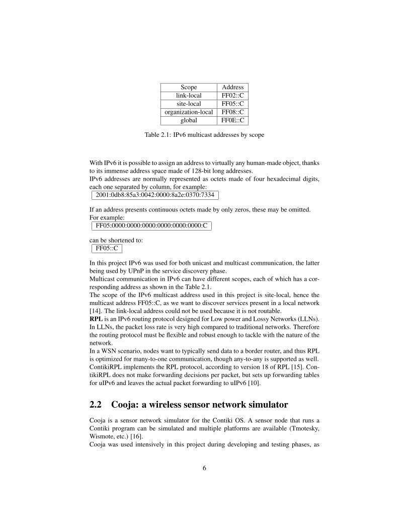
Scope Addresslink-local FF02::Csite-local FF05::C
organization-local FF08::Cglobal FF0E::C
Table 2.1: IPv6 multicast addresses by scope
With IPv6 it is possible to assign an address to virtually any human-made object, thanksto its immense address space made of 128-bit long addresses.IPv6 addresses are normally represented as octets made of four hexadecimal digits,each one separated by column, for example:
2001:0db8:85a3:0042:0000:8a2e:0370:7334
If an address presents continuous octets made by only zeros, these may be omitted.For example:
FF05:0000:0000:0000:0000:0000:0000:C
can be shortened to:FF05::C
In this project IPv6 was used for both unicast and multicast communication, the latterbeing used by UPnP in the service discovery phase.Multicast communication in IPv6 can have different scopes, each of which has a cor-responding address as shown in the Table 2.1.The scope of the IPv6 multicast address used in this project is site-local, hence themulticast address FF05::C, as we want to discover services present in a local network[14]. The link-local address could not be used because it is not routable.RPL is an IPv6 routing protocol designed for Low power and Lossy Networks (LLNs).In LLNs, the packet loss rate is very high compared to traditional networks. Thereforethe routing protocol must be flexible and robust enough to tackle with the nature of thenetwork.In a WSN scenario, nodes want to typically send data to a border router, and thus RPLis optimized for many-to-one communication, though any-to-any is supported as well.ContikiRPL implements the RPL protocol, according to version 18 of RPL [15]. Con-tikiRPL does not make forwarding decisions per packet, but sets up forwarding tablesfor uIPv6 and leaves the actual packet forwarding to uIPv6 [10].
2.2 Cooja: a wireless sensor network simulatorCooja is a sensor network simulator for the Contiki OS. A sensor node that runs aContiki program can be simulated and multiple platforms are available (Tmotesky,Wismote, etc.) [16].Cooja was used intensively in this project during developing and testing phases, as
6

Figure 2.2: Cooja Simulator
doing the same on the real hardware would be very time-consuming. Cooja allows tospeed up, slow down or pause simulations.The Log Listener prints out whatever comes from the nodes’ serial ports. The radiologger permits to analyze packets that are sent and received by nodes, which is a usefulfeature for debugging. The timeline is used to ensure that the nodes’ behaviour iscoherent with the intended purpose.Figure 2.2 is a screenshot that shows the Cooja simulation environment.
2.3 Hardware platforms for ContikiExperiments were performed on two different sensor node platforms: Tmote Sky andWismote. Wismotes have a much bigger flash memory, which came in handy for stor-ing the XML messages used by UPnP.
2.3.1 Tmote SkyTmote Sky has a 8MHz Texas Instruments MSP430 microcontroller, based on a 16-bitRISC architecture. It has 10k of RAM and 48k of Flash memory. For communication ituses a Chipcon Wireless Transceiver CC2420, bit-rate 250kbps, frequency of 2.4GHzand compatible with the IEEE 802.15.4 standard. It is equipped with three LEDs andtemperature, humidity and light sensors [17].
7

Figure 2.3: Tmote Sky
Figure 2.4: Wismote
2.3.2 WismoteThe Wismote platform has a Texas Instruments MSP430 series 5 microcontroller whichallows 20-bit memory addressing, 16kB internal RAM and 256kB Flash. The radio,TI CC2520, is compatible with the IEEE 802.15.4 standard, frequency 2.4GHz withsupport for 6LoWPAN/Zigbee/WirelessHart [18].
2.4 Service Discovery
2.4.1 UPnPThe UPnP Architecture defines a set of protocols designed for being easy-to-use, flex-ible, for providing standards-based connectivity to ad-hoc or unmanaged networkswhether in the home, in a small business, public spaces, or attached to the Internet[7].UPnP is mainly used for dynamically establish network connections and let deviceslearn about each other’s presence and capabilities. After the device has joined a net-
8

work and established connections with its peers, it can perform operations such ascontrol, data transfer etc. [8].UPnP leverages the Internet stack of protocols to attain high levels of compatibility, ontop of which standard format XML messages are exchanged.Further specifications about parts of UPnP used in this project are described in the fol-lowing paragraphs.Service DiscoveryService Discovery in UPnP is done through the Simple Service Discovery Protocol(SSDP). When a device is added to a network, it can advertise its services to the con-trol points (i.e. the clients). It is also possible to communicate the withdrawal of theservice. Control points can execute search operations to discover services present inthe network.Search RequestAccording to the standard, the format of each message is reported:
M-SEARCH * HTTP/1.1HOST: FF05::C:1900MAN: "ssdp:discover"MX: seconds to delay responseST: search targetUSER-AGENT: OS/version UPnP/1.1 product/version
Search requests are sent over UDP and the destination address of the is the IPv6 site-local multicast address FF05::C with port number 1900. A UPnP-enabled device thatis listening on the socket with this address and port number will reply by sending to theclient a UDP unicast packet containing the response.Search Response
HTTP/1.1 200 OKCACHE-CONTROL: max-age = seconds until advertisement expiresDATE: when response was generatedEXT:LOCATION: URL for UPnP description for root deviceSERVER: OS/version UPnP/1.1 product/versionST: search targetUSN: composite identifier for the advertisementBOOTID.UPNP.ORG: number increased each time device sends an initial announceor an update messageCONFIGID.UPNP.ORG: number used for caching description informationSEARCHPORT.UPNP.ORG: number identifies port on which device responds tounicast M-SEARCH
Search responses are sent over UDP and the destination address is the source addressof the search request. In the search response it is important to notice the LOCATIONfield, which can be used by the requesting device to retrieve information about the de-vice type and the services it provides.Control
9

Once the control point has fetched the description file of a device, it knows the lo-cation of the description files of its services. These files must be fetched for eachservice the control points wants to send actions to. Actions to services can be sentthrough the Simple Object Access Protocol (SOAP). SOAP relies on XML messagesover HTTP. When a device receives a SOAP control request from a control point, itparses the SOAP request and executes the required action, returning any specific re-sponse (a SOAP message as well) to the control point (i.e. the client) [7].SOAP control request format
POST path control URL HTTP/1.HOST: hostname:portNumberCONTENT-LENGTH: bytes in bodyCONTENT-TYPE: text/xml; charset="utf-8"USER-AGENT: OS/version UPnP/1.1 product/versionSOAPACTION: "urn:schemas-upnp-org:service:serviceType:v#actionName"<?xml version="1.0"?><s:Envelopexmlns:s="http://schemas.xmlsoap.org/soap/envelope/"s:encodingStyle="http://schemas.xmlsoap.org/soap/encoding/"><s:Body><u:actionName xmlns:u="urn:schemas-upnp-org:service:serviceType:v"><argumentName>in arg value</argumentName><!– other in args and their values go here, if any –></u:actionName></s:Body></s:Envelope>
EventingIn the service description file, devices publish a list of evented variables. Control pointscan subscribe to the events of a service by using the subscription URL located in thedevice description file. Upon subscription they will receive updates when the value ofevented variables change.Event message format
10

NOTIFY delivery path HTTP/1.0HOST: delivery host:delivery portCONTENT-TYPE: text/xml; charset="utf-8"NT: upnp:eventNTS: upnp:propchangeSID: uuid:subscription-UUIDSEQ: event keyCONTENT-LENGTH: bytes in body<?xml version="1.0"?><e:propertyset xmlns:e="urn:schemas-upnp-org:event-1-0"><e:property><variableName>new value</variableName></e:property>Other variable names and values (if any) go here.</e:propertyset>
2.4.2 mDNSAnother technology for discovery of network services is Multicast DNS (mDNS). Itis part of Zeroconf [22], and it is used by Apple’s Bonjour and others. It leveragesthe DNS programming interfaces, packet formats and operating semantics, and it isprimarily intended to operate in small networks where no DNS server is installed. AsUPnP, mDNS also relies on UDP over IP multicast communication.With mDNS, it is possible to do host and service discovery.In host discovery, a client interested in knowing the IP address for a given host namesends a multicast query message in the local network. The host with the queried hostname will reply (also with a multicast message), and all the machines of the subnet willupdate their mDNS cache accordingly.Service discovery is done in a similar way to host discovery, but in the query message itis specified that the target of the search is a PTR (pointer record) instead of A (addressrecord) [19].
2.5 Related work
2.5.1 Service Discovery in Wireless Sensor NetworksThe problem of allowing sensor nodes to advertise the resources they hold is not new.The authors of [20] implemented mDNS in a small wireless sensor network target node.With this implementation sensor nodes can advertise and host services through mDNS.The main benefit of allowing sensor nodes to communicate with UPnP is to achieveinteroperability with millions of local network devices that already use the set of stan-dard protocols specified in the UPnP architecture.By using standard widespread protocols we envision a service-oriented architecture, inwhich the client is not concerned about the technology hosting the services.Resource richer sensor node platforms like Wismote are coming out, and the same time
11

this thesis has investigated how it is possible to shrink UPnP in order to allow tinier de-vices to exploit its advantages.
2.5.2 CoAPThe Constrained Application Protocol (CoAP) is an application layer protocol designedfor resource-constrained network devices (typically sensor nodes with small amountsof ROM and RAM and 8-bit microcontrollers). CoAP is designed to be easily inter-faced to HTTP in order to integrate with web applications while causing a low over-head.The protocol is intended for usage in machine-to-machine (M2M) applications, suchas smart energy and building automation [21].CoAP messages can be of type request and response, which are typically encapsulatedin UDP packets. Clients can use Multicast CoAP to find servers, in which a request ismade to a IP multicast group instead of a CoAP end-point.Service discovery takes place when a client queries a server for its list of hosted re-sources and learns one or more URI that reference resources in the namespace of theserver.The CoAP protocol is interesting because it may be used in future to replace certainparts of a UPnP transaction, for example, the service control part that is currently han-dled by SOAP.
12

Chapter 3
Design and implementation
In this chapter the system architecture is unveiled and the behaviour of the softwarecomponents that were designed and implemented is described.
3.1 System architectureProtocols like SSDP and COAP leverage the the transport layer (UDP and TCP re-spectively). Once a working configuration between two peers has been established,higher-level applications may be using it. Therefore, in the protocols stack, the UPnPset of protocols can be considered as a middleware between the UDP/TCP layer andthe application layer, as represented in Figure 3.1.
In a typical UPnP usage scenario, a client will send search requests to discoverneighbouring devices’ services. Once the client is informed of the services providedby a device, it may begin to use a service by sending commands, and the responder willreply by supplying the requested information or executing an action [7].A full UPnP transaction can be therefore summarized in the following steps:
1. client sends SEARCH request
2. responder sends SEARCH response (containing device description file’s url)
3. client fetches device description file (containing services description file’s url)
4. client fetches description of services in which it is interested
5. client may send:
(a) subscription request to a service
(b) update request of an evented variable
(c) control request (to control url)
13

Figure 3.1: UPnP in the protocol stack
14

Figure 3.2: System architecture
15

6. responder may send:
(a) subscription OK message / updates (notify) upon change of evented vari-able
(b) update (soap)
(c) control OK response
Figure 3.3 shows a possible UPnP transaction represented as a sequence diagram.As shown in the figure, the first phase is service discovery followed by the retrieval
of the device and service description files from the web server. Consequently the clientknows the service’s specifics and can start to use it by sending requests and actions.
3.2 Implementation
3.2.1 UPnP in ContikiThe UPnP-responder implementation in Contiki is divided in two main threads: Re-sponder and Webserver.Responder waits for incoming search requests from control points to the IPv6 multi-cast address FF05::C and at UDP port 1900. When a search request is received, a UDPunicast packet containing the search response will be sent. The search response is thefirst acknowledgement of the device’s presence and contains the URL that locates thedevice’s description file, in addition to other information such as the device type andid. This behaviour is implemented as a process thread.The two main functions of the Webserver thread are to deliver UML descriptions andhandle control requests. The UML descriptions delivered are the device and services’descriptions.The other requests that the Webserver thread handles might be control, subscription orupdate requests. After retrieving the service description files, a control point is awareof the commands it needs to send in order to query a specific service provided by theresponder. Requests to the web server are sent to TCP port number 5790.The Web Server is divided in:
• a process thread that waits for incoming connections
• a protothread that handles serves the incoming requests by supplying the re-quested resource or executing the action by triggering an actuator (i.e. switchlight on or off)
An additional protothread is used to periodically refresh the values read from the sen-sors, which the web server might supply to a client upon request.
3.2.2 Development toolchain and UPnP IPv6 clientUPnP responder: a device that runs Contiki and is able to respond to UPnP multicastsearch requests, as well as executing commands sent by a client in order to receive
16

Figure 3.3: UPnP transaction diagram
17

sensor information or perform actuator control.Slip-radio: a contiki running device that converts the data it receives on the serial portin IP traffic over the radio and vice-versa.Native border router: it is a process running in linux which forwards traffic directedto AAAA::/64 to the serial port. It is the bridge between UPnP clients and the WSN(by communicating directly with slip-radio).UPnP client: The UPnP-client is a process that sends UPnP requests to the IPv6 site-local multicast address FF05::C and receives responses. A java program (the GUI beingshown in Figure 3.5) was developed for this purpose.The primary function of the UPnP client is to send multicast search requests, and dis-play search responses. It can also send HTTP GET requests to fetch device and servicedescription files. Moreover, the GUI allows the user to subscribe and use the servicesof a UPnP-responder node, which in the present case of study is able to provide twoservices: temperature information and lamp switch (simulated by the node’s LEDs).When the client receives updated data from a sensor node in the form of a SOAP mes-sage, this is parsed and the information of interest is shown on the GUI (for examplethe current temperature value or whether the lamp is on or off).For debugging and testing purposes, the UPnP client also has a facility to receive onthe multicast socket (thus being able to receive other device’s search requests as wellas its own). The Web server contained in the responder was also tested with regularweb browsers.Furthermore, it is possible to communicate from an external process with every nodewithin the sensor network simulated in Cooja by using the Native-Border-Router, afeature that was very useful in the project to send the requests from the UPnP client, asshown in Figure 3.4. Extensive simulations were conducted in Cooja during the imple-mentation phase.
18

Figure 3.4: Simulation architecture
19

Figure 3.5: UPnP IPv6 client
20
Chapter 4
Evaluation
The evaluation was conducted by testing and assessing various properties of the UPnPimplementation both in the Cooja simulator and on real nodes, using both Tmote Skyand Wismotes.Radio duty-cycling was also employed to study the relation of energy consumption andlatency of response.In Contiki, a duty-cycling mechanism is implemented under the name of ContikiMAC.Energy consumption of a full UPnP transaction was experimentally quantified whenusing duty-cycling.
4.1 Experiments on hardware platformsThe target hardware platforms used in the project were Tmote Sky and Wismote. Ex-periments were conducted with real hardware in a similar fashion to Cooja simulations,with UPnP IPv6 client and native border router on the Linux side, and the nodes run-ning slip radio and UPnP responder on the WSN side. This schema is shown in Figure4.1, where one Tmote Sky was used as slip-radio and a Wismote as UPnP responder.One problem running UPnP responder on a Tmote sky as target platform, was the sizeof the UPnP messages (e.g. device and service description files) that need to be storedin a responder device. The Tmote Sky quickly ran out of flash memory, hence the needto use a platform with larger memory which made the choice lean towards the Wismoteplatform. The slip-radio node connects the WSN to the rest of the world through thenative border router. For this purpose a Tmote sky is sufficient.
4.2 Energy consumption and latency evaluationAs previously stated, minimizing energy consumption is an important requirement inmany WSNs. In order to attain this, a technique called "Radio Duty-cycling" is used toalternate short periods of radio listening and long periods of radio sleeping.When the nodes need to receive or transmit a message, power is consumed. Evaluation
21

Figure 4.1: Experiment setup
22

UPnP message Size (bytes)Number of
TCP packetsrequired
Device description XML file 776 17Service description XML file 660 14
Temperature update 406 9LED status update 370 8
Table 4.1: Size of UPnP messages and TCP packets required to transmit them
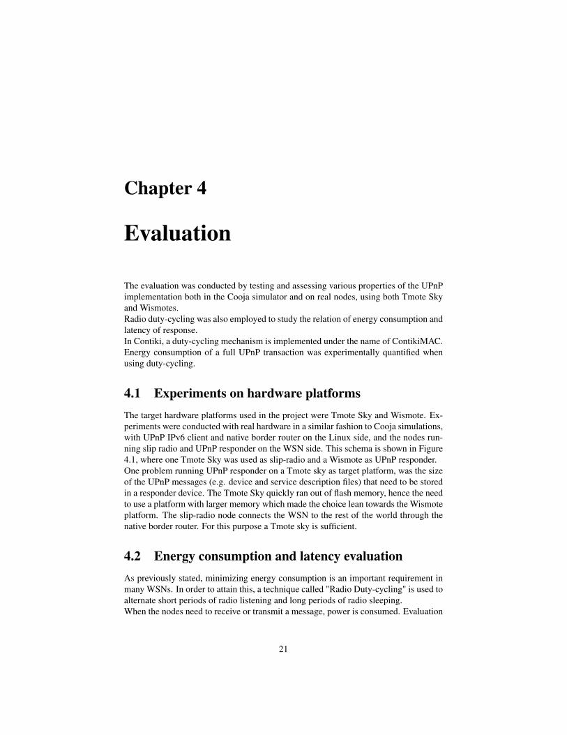
was conducted in order to assess how much the length of the UPnP messages affectsthe overall energy consumption. Duty-cycling increases latency and slows down thenetwork responsiveness. If a sensor node periodically turns off its radio instead oflistening, it will be slower in replying to the UPnP requests that are sent from theclients.
Table 4.1 reports the size and the number of packets needed to transmit each UPnPmessage, combined with information about latency with and without radio duty-cycling.
Figure 4.2 shows that the latency increases roughly of a factory of 3 when duty-cycle is used. The values of the latency are consistent with the messages’ size reportedin 4.1. These measurement were conducted by an automated client program that re-quested each resource 30 times and then calculated the average value.The average duty-cycle value, which means the percentage of time in which the radiowas in ON state (either transmitting, listening or receiving ), was at 0.8% when theseexperiments were carried out.
4.3 Optimizations to UPnP in ContikiIn order to allow the UPnP protocol to run faster and consume less energy on resourceconstrained devices, a number of simplifications were tested on the responder side.This included shrinking update message size to only one TCP packet, by only includ-ing essential information.For example, the content of 4.2 was shortened as shown in 4.3.
Another optimization was having a unique URL for each action (subscribe, update,control) of each service. This allows the responder to immediately identify the type ofrequest and the service involved, without the need to process a lengthy incoming SOAPmessage.In the study case of duty-cycle on and given a UPnP transaction of ten requests fortemperature updates, the average duty-cycle decreased from 0.8 to 0.64, as shown inFigure 4.3. The energy consumption of the radio would thereby be reduced by 20%,
23
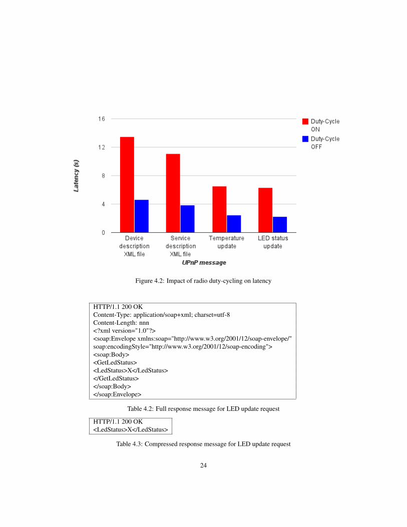
Figure 4.2: Impact of radio duty-cycling on latency
HTTP/1.1 200 OKContent-Type: application/soap+xml; charset=utf-8Content-Length: nnn<?xml version="1.0"?><soap:Envelope xmlns:soap="http://www.w3.org/2001/12/soap-envelope/"soap:encodingStyle="http://www.w3.org/2001/12/soap-encoding"><soap:Body><GetLedStatus><LedStatus>X</LedStatus></GetLedStatus></soap:Body></soap:Envelope>
Table 4.2: Full response message for LED update request
HTTP/1.1 200 OK<LedStatus>X</LedStatus>
Table 4.3: Compressed response message for LED update request
24

which in the long run increases the network’s life-time.Figure 4.4 shows that in case of no duty-cycle the average latency for receiving oneupdate message improves from 4.0 to 3.5 seconds on Tmote Sky. The reason whythe improvement is relatively small even shrinking the response message, is that therequest message has not been shrunk. The transmission of the request message stilldominates the latency.An improvement that could dramatically speed up the service discovery phase is creat-ing standard interfaces for services, and defining standard type of devices that providecertain kinds of services.Figure 4.2 shows most of the time is spent by the client retrieving the device and ser-vice description files. If this phase could be skipped, the client could immediately jumpto using the service after receiving the Search response from the UPnP Responder.If we know by the type of the UPnP-enabled Contiki device that it will always providea certain type of service (e.g. Temperature sensing service), and that the interface foraccessing that service is always the same, we can program smarter clients that are ableto skip the retrieval of the heavy-weight description files.In order to fully take advantage of this mechanism, further work should be conductedto standardize the UPnP implementation in Contiki and create templates of deviceswhose services can be accessed with a standard and well-known interface. Defining astandard service interface primarily means defining standard URLs for sending com-mands to the service.The gain of this optimization was quantified as shown in Figure 4.5, where we can seethat the latency of the service discovery phase would decrease by 65% and 63% withand without radio duty-cycling respectively.
4.4 DiscussionThe primary application scenarios for which the UPnP implementation for Contiki isintended are smart energy, smart plugs, temperature sensors etc.The current implementation only handles uni-hop multicast, which entails that it is pos-sible to reach a responder at a distance of one hop from the border router. Multi-hopmulticast is currently supported in Contiki with netflooding, which is used to spreada message across the network from one point. However in the case of UPnP, with re-sponses that must be sent from each UPnP-responder in the network, difficulties mayarise if these all do so at the same time.In order to make the protocol more efficient and fit it into tinier platform like TmoteSky, the messages describing the device and its services may be shrunk and simplifiedfor the context of WSN. Shrinking the size of the description files may also be benefi-cial from the energy point of view in combination with radio duty-cycling. If the nodescommunicate less and for shorter periods of time they can save energy and prolong thesensor network’s life-time.As we have observed in the evaluation duty-cycling introduces certain latencies. De-pending on the application requirements, the system designers ought to determinereasonable trade-offs between energy consumption and network responsiveness, andwhether to employ radio duty-cycling or not.
25
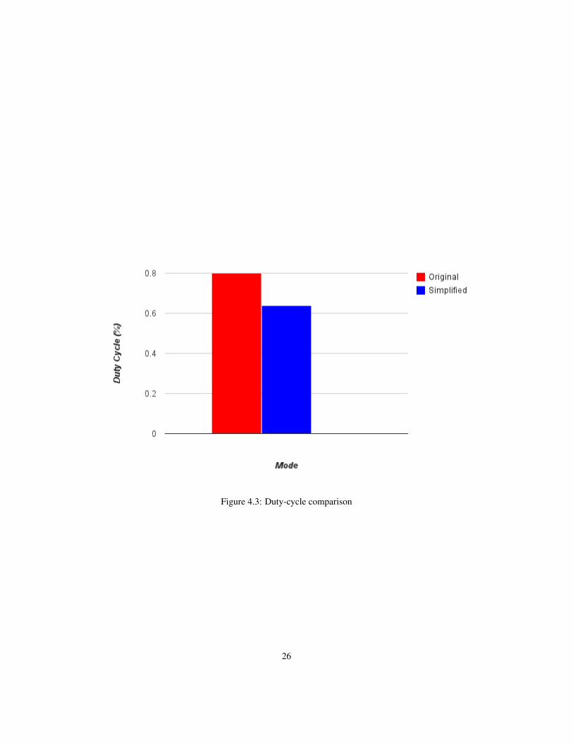
Figure 4.3: Duty-cycle comparison
26

Figure 4.4: Average latency of one update message comparison
27

Figure 4.5: Latency reduction with Service Caching
28

A scenario in which multiple responders are present was studied. In this case, the re-sponders will try to reply to a multicast request at the same time, which might causethe slip-radio to drop some packets and lose one of the responses. A solution to thisproblem could be to respond with a random delay, which would help minimizing theprobability of packet loss.Another issue is that due to the unreliable nature of UDP and the high packet-loss-ratetypical of WSNs, it is possible that a device fails to discover the presence of UPnP-enabled sensor nodes. The UPnP clients must be aware of this and implement mecha-nisms to re-send their requests when needed.
29

Chapter 5
Conclusions and Future work
In this thesis, a UPnP prototype over IPv6 was implemented for Contiki. The con-tribution of this thesis is showing that it is feasible to use the UPnP set of protocolsin wireless sensor networks. The implementation was evaluated with regard to energyconsumption and latency of response. Furthermore, simplifications were made to makethe protocol more efficient.Even without simplifications, the advent of larger platforms such as Wismote is allow-ing sensor nodes to run more and more complex software, therefore UPnP could soonbe run smoothly in many sensor networks application scenarios.This thesis shows that it is possible to do service discovery, as well as utilizing theservices provided by sensor nodes.Depending on the application scenario, the system designer should decide if deployingthe protocol in combination with radio duty-cycling.Tests were conducted both in software and hardware to ensure that the implementationworks and produces expected results.The main obstacles in this project were using Tmote Sky hardware that has very lim-ited flash memory resources. Fitting the program code into these nodes was sometimesimpossible, especially in combination with debug, duty-cycling or power measurementfeatures. Therefore, most of the evaluation was done with Wismote nodes simulated inCooja.Future work in this field may target optimizing, especially on the client side, the UPnPimplementation for applications where low energy consumption or latency are strictrequirements, or the employed platform does not provide enough memory to run fullUPnP.A lighter version of the protocol should be specified and standardized for severely con-strained environments, to make the interaction client-responder faster and simpler.The support for multicast multihop is also an area of interest. The main problem wouldbe avoiding all the responders to simultaneously reply to the same request as it spreadsacross the wireless network, thereby obstructing each other’s response. Further workshould be conducted to find the best solutions.Finally, more features could be added and supported, such as searching for a specificservice by the client.
30

Bibliography
[1] F.L. Lewis. Wireless sensor networks. Smart Environments: Technologies, Pro-tocols, and Applications, pages 11–46, 2004.
[2] J. Polastre, R. Szewczyk, A. Mainwaring, D. Culler, and J. Anderson. Analysis ofwireless sensor networks for habitat monitoring. Wireless sensor networks, pages399–423, 2004.
[3] V. Shnayder, B. Chen, K. Lorincz, T.R.F.F. Jones, and M. Welsh. Sensor networksfor medical care. In Conference On Embedded Networked Sensor Systems: Pro-ceedings of the 3 rd international conference on Embedded networked sensorsystems, volume 2, pages 314–314, 2005.
[4] R. Van Kranenburg, E. Anzelmo, A. Bassi, D. Caprio, S. Dodson, and M. Ratto.The internet of things. A critique of ambient technology and the all-seeing net-work of RFID, Network Notebooks, 2, 2008.
[5] S. Roundy, D. Steingart, L. Frechette, P. Wright, and J. Rabaey. Power sourcesfor wireless sensor networks. Wireless Sensor Networks, pages 1–17, 2004.
[6] F. Zhu, M. Mutka, and L. Ni. Classification of service discovery in pervasivecomputing environments. Michigan State University, East Lansing, available athttp://www. cse. msu. edu/˜ zhufeng/ServiceDiscoverySurvey. pdf MSU-CSE-02-24, 2002.
[7] UPnP Forum. UPnP Device Architecture 1.1, http://upnp.org/specs/arch/UPnP-arch-DeviceArchitecture-v1.1.pdf.
[8] Microsoft Corporation. Understanding Universal Plug and Play, http://www.upnp.org/download/UPNP_understandingUPNP.doc 2000.
[9] A. Dunkels, B. Gronvall, and T. Voigt. Contiki-a lightweight and flexible operat-ing system for tiny networked sensors. In Local Computer Networks, 2004. 29thAnnual IEEE International Conference on, pages 455–462. IEEE, 2004.
[10] J.G. Ko, J. Eriksson, N. Tsiftes, S. Dawson-Haggerty, A. Terzis, A. Dunkels,and D. Culler. Contikirpl and tinyrpl: Happy together. In Proceedings of theworkshop on Extending the Internet to Low power and Lossy Networks (IP+ SN2011), 2011.
31

[11] A. Dunkels. The contikimac radio duty cycling protocol. 2011.
[12] Contiki Wiki. http://www.sics.se/contiki/wiki/index.php/Change_MAC_or_Radio_Duty_Cycling_Protocols.
[13] FinanzNachrichten.de http://www.finanznachrichten.de/nachrichten-2008-10/12014846-atmel-cisco-and-the-swedish-institute-of-computer-science-sics-collaborate-to-support-a-future-where-any-device-can-be-connected-to-the-internet-008.htm.
[14] Network Working Group . Internet Protocol, Version 6 (IPv6). Request for Com-ments: 2460.
[15] T. Winter. Rpl: Ipv6 routing protocol for low-power and lossy networks. 2012.
[16] F. Osterlind, A. Dunkels, J. Eriksson, N. Finne, and T. Voigt. Cross-level sensornetwork simulation with cooja. In Local Computer Networks, Proceedings 200631st IEEE Conference on, pages 641–648. IEEE, 2006.
[17] Tmote Sky datasheet. http://www.eecs.harvard.edu/~konrad/projects/shimmer/references/tmote-sky-datasheet.pdf.
[18] Wismote specifications. http://wismote.org/doku.php?id=specification.
[19] Multicast DNS. http://www.multicastdns.org/.
[20] Å. Östmark, J. Eliasson, P. Lindgren, A. Halteren, and L. Meppelink. An infras-tructure for service oriented sensor networks. Journal of Computers, 1(5):20–29,2006.
[21] CoRE Working Group. Constrained Application Protocol (CoAP). Internet-Draftdraft-ietf-core-coap-11, 2012.
[22] Zeroconf. http://www.zeroconf.org/.
32

Appendix
33

Appendix A
Figure 1: Poster for SICS Open House on 26 April, 2012