Embed Size (px)
Citation preview
Service Instruction43/68-11 EN
Electrical Part Turn Actuators forContinuous Modulating Control
RHD250 ... RHD4000 (Contrac)Rated Torque 250 ... 4000 Nm
(200...3000 ft-lbs)
P R O F I
B U S
PROCESS FIELD BUS
®
Electrical Part Turn Actuators for Continuous Modulating Control RHD250 ... RHD4000 (Contrac)
Service InstructionDocument No. 43/68-11 ENIssued: December 2005
Manufacturer:ABB Automation Products GmbHSchillerstr. 7232425 MindenGermany
Tel: +49 551 905-534Fax: +49 551 905-555
© Copyright 2005 by ABB Automation Products GmbHWe reserve the right to technical amendments
This document is protected by copyright. Information in this document is intended only to assist theuser in safe and efficient operation of the equipment. Its contents are not to be reproduced in full orpart without prior approval of legal owner.
2 Electrical Part Turn Actuators for Continuous Modulating Control RHD250 ... RHD4000 (Contrac) 43/68-11 EN
Content . . . . . . . . . . . . . . . . . . . . . . . . . . . . . . . . . . . . . . . . . . . . . . . . . . . . . . . . . . . . . . . . . . . Page
Important information . . . . . . . . . . . . . . . . . . . . . . . . . . . . . . . . . . . . . . . . . . . . . . . . . . . . . . . . . . . 4General . . . . . . . . . . . . . . . . . . . . . . . . . . . . . . . . . . . . . . . . . . . . . . . . . . . . . . . . . . . . . . . . . . . . . . 4Symbols . . . . . . . . . . . . . . . . . . . . . . . . . . . . . . . . . . . . . . . . . . . . . . . . . . . . . . . . . . . . . . . . . . . . . . 4Transport and storage . . . . . . . . . . . . . . . . . . . . . . . . . . . . . . . . . . . . . . . . . . . . . . . . . . . . . . . . . . . . 4
Introduction . . . . . . . . . . . . . . . . . . . . . . . . . . . . . . . . . . . . . . . . . . . . . . . . . . . . . . . . . . . . . . . . . . . 5Safety and precautions . . . . . . . . . . . . . . . . . . . . . . . . . . . . . . . . . . . . . . . . . . . . . . . . . . . . . . . . . . . . 5Tools . . . . . . . . . . . . . . . . . . . . . . . . . . . . . . . . . . . . . . . . . . . . . . . . . . . . . . . . . . . . . . . . . . . . . . . . 5
Lubrication. . . . . . . . . . . . . . . . . . . . . . . . . . . . . . . . . . . . . . . . . . . . . . . . . . . . . . . . . . . . . . . . . . . . 6Mounting position and filling capacity . . . . . . . . . . . . . . . . . . . . . . . . . . . . . . . . . . . . . . . . . . . . . . . . . . 6Oil specifications . . . . . . . . . . . . . . . . . . . . . . . . . . . . . . . . . . . . . . . . . . . . . . . . . . . . . . . . . . . . . . . . 7
Maintenance . . . . . . . . . . . . . . . . . . . . . . . . . . . . . . . . . . . . . . . . . . . . . . . . . . . . . . . . . . . . . . . . . . 8Lever . . . . . . . . . . . . . . . . . . . . . . . . . . . . . . . . . . . . . . . . . . . . . . . . . . . . . . . . . . . . . . . . . . . . . . . . 8Sealing ring of output drive shaft . . . . . . . . . . . . . . . . . . . . . . . . . . . . . . . . . . . . . . . . . . . . . . . . . . . . 10Sealing ring of hand wheel drive / hand wheel shaft . . . . . . . . . . . . . . . . . . . . . . . . . . . . . . . . . . . . . . . . 11Sealing of the position sensor drive . . . . . . . . . . . . . . . . . . . . . . . . . . . . . . . . . . . . . . . . . . . . . . . . . . . 12RHD1250... RHD4000 . . . . . . . . . . . . . . . . . . . . . . . . . . . . . . . . . . . . . . . . . . . . . . . . . . . . . . . . . . . . 13Motor . . . . . . . . . . . . . . . . . . . . . . . . . . . . . . . . . . . . . . . . . . . . . . . . . . . . . . . . . . . . . . . . . . . . . . . 14Brake adjustment . . . . . . . . . . . . . . . . . . . . . . . . . . . . . . . . . . . . . . . . . . . . . . . . . . . . . . . . . . . . . . . 20
Electrical Connection. . . . . . . . . . . . . . . . . . . . . . . . . . . . . . . . . . . . . . . . . . . . . . . . . . . . . . . . . . . 22General . . . . . . . . . . . . . . . . . . . . . . . . . . . . . . . . . . . . . . . . . . . . . . . . . . . . . . . . . . . . . . . . . . . . . 22Covers . . . . . . . . . . . . . . . . . . . . . . . . . . . . . . . . . . . . . . . . . . . . . . . . . . . . . . . . . . . . . . . . . . . . . . 22Wiring diagrams . . . . . . . . . . . . . . . . . . . . . . . . . . . . . . . . . . . . . . . . . . . . . . . . . . . . . . . . . . . . . . . 23Fuses . . . . . . . . . . . . . . . . . . . . . . . . . . . . . . . . . . . . . . . . . . . . . . . . . . . . . . . . . . . . . . . . . . . . . . . 25
Exchange of position sensor . . . . . . . . . . . . . . . . . . . . . . . . . . . . . . . . . . . . . . . . . . . . . . . . . . . . . 29Dismounting . . . . . . . . . . . . . . . . . . . . . . . . . . . . . . . . . . . . . . . . . . . . . . . . . . . . . . . . . . . . . . . . . . 29Mounting . . . . . . . . . . . . . . . . . . . . . . . . . . . . . . . . . . . . . . . . . . . . . . . . . . . . . . . . . . . . . . . . . . . . 29
Electrical Test Values. . . . . . . . . . . . . . . . . . . . . . . . . . . . . . . . . . . . . . . . . . . . . . . . . . . . . . . . . . . 30Test values (position sensor) . . . . . . . . . . . . . . . . . . . . . . . . . . . . . . . . . . . . . . . . . . . . . . . . . . . . . . . 30Test values . . . . . . . . . . . . . . . . . . . . . . . . . . . . . . . . . . . . . . . . . . . . . . . . . . . . . . . . . . . . . . . . . . . 30Winding resistance (motor) . . . . . . . . . . . . . . . . . . . . . . . . . . . . . . . . . . . . . . . . . . . . . . . . . . . . . . . . 30
Failure detection . . . . . . . . . . . . . . . . . . . . . . . . . . . . . . . . . . . . . . . . . . . . . . . . . . . . . . . . . . . . . . 32LED signals at the local control panel . . . . . . . . . . . . . . . . . . . . . . . . . . . . . . . . . . . . . . . . . . . . . . . . . 32
Trouble Shooting . . . . . . . . . . . . . . . . . . . . . . . . . . . . . . . . . . . . . . . . . . . . . . . . . . . . . . . . . . . . . . 32General . . . . . . . . . . . . . . . . . . . . . . . . . . . . . . . . . . . . . . . . . . . . . . . . . . . . . . . . . . . . . . . . . . . . . 33Failures at brake, fuse or wiring . . . . . . . . . . . . . . . . . . . . . . . . . . . . . . . . . . . . . . . . . . . . . . . . . . . . . 34Operation mode (MAN / AUT) . . . . . . . . . . . . . . . . . . . . . . . . . . . . . . . . . . . . . . . . . . . . . . . . . . . . . . . 35Input configuration . . . . . . . . . . . . . . . . . . . . . . . . . . . . . . . . . . . . . . . . . . . . . . . . . . . . . . . . . . . . . . 36Operation behind step controller . . . . . . . . . . . . . . . . . . . . . . . . . . . . . . . . . . . . . . . . . . . . . . . . . . . . 37Failure Diagram . . . . . . . . . . . . . . . . . . . . . . . . . . . . . . . . . . . . . . . . . . . . . . . . . . . . . . . . . . . . . . . . 37Failure due to response of positioning loop monitoring . . . . . . . . . . . . . . . . . . . . . . . . . . . . . . . . . . . . . . 38General . . . . . . . . . . . . . . . . . . . . . . . . . . . . . . . . . . . . . . . . . . . . . . . . . . . . . . . . . . . . . . . . . . . . . 38User Interface Menus . . . . . . . . . . . . . . . . . . . . . . . . . . . . . . . . . . . . . . . . . . . . . . . . . . . . . . . . . . . . 39
43/68-11 EN Electrical Part Turn Actuators for Continuous Modulating Control RHD250 ... RHD4000 (Contrac) 3
1 Important information
1.1 GeneralRead and save all instructions prior to installing, operating, and servicing this product. If any of theinstructions are not understood, contact your ABB representative for clarification.
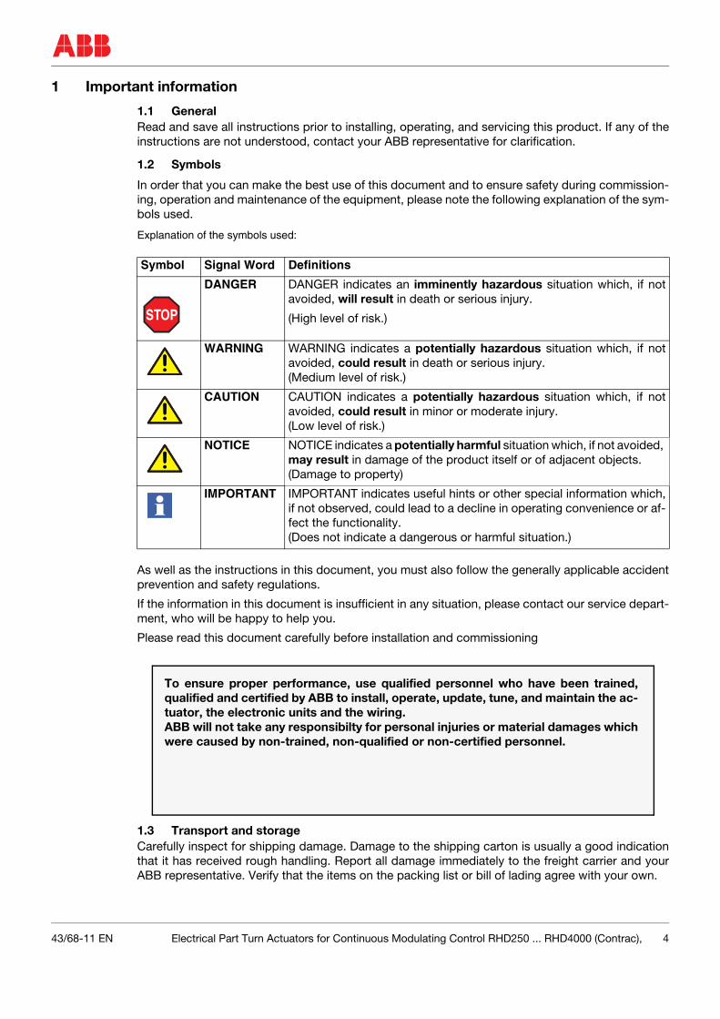
1.2 Symbols
In order that you can make the best use of this document and to ensure safety during commission-ing, operation and maintenance of the equipment, please note the following explanation of the sym-bols used.
Explanation of the symbols used:
As well as the instructions in this document, you must also follow the generally applicable accidentprevention and safety regulations.
If the information in this document is insufficient in any situation, please contact our service depart-ment, who will be happy to help you.
Please read this document carefully before installation and commissioning
1.3 Transport and storageCarefully inspect for shipping damage. Damage to the shipping carton is usually a good indicationthat it has received rough handling. Report all damage immediately to the freight carrier and yourABB representative. Verify that the items on the packing list or bill of lading agree with your own.
Symbol Signal Word Definitions
STOP
DANGER DANGER indicates an imminently hazardous situation which, if notavoided, will result in death or serious injury.
(High level of risk.)
WARNING WARNING indicates a potentially hazardous situation which, if notavoided, could result in death or serious injury.(Medium level of risk.)
CAUTION CAUTION indicates a potentially hazardous situation which, if notavoided, could result in minor or moderate injury.(Low level of risk.)
NOTICE NOTICE indicates a potentially harmful situation which, if not avoided, may result in damage of the product itself or of adjacent objects.(Damage to property)
IMPORTANT IMPORTANT indicates useful hints or other special information which,if not observed, could lead to a decline in operating convenience or af-fect the functionality. (Does not indicate a dangerous or harmful situation.)
To ensure proper performance, use qualified personnel who have been trained,qualified and certified by ABB to install, operate, update, tune, and maintain the ac-tuator, the electronic units and the wiring.ABB will not take any responsibilty for personal injuries or material damages whichwere caused by non-trained, non-qualified or non-certified personnel.
43/68-11 EN Electrical Part Turn Actuators for Continuous Modulating Control RHD250 ... RHD4000 (Contrac), 4
Introduction
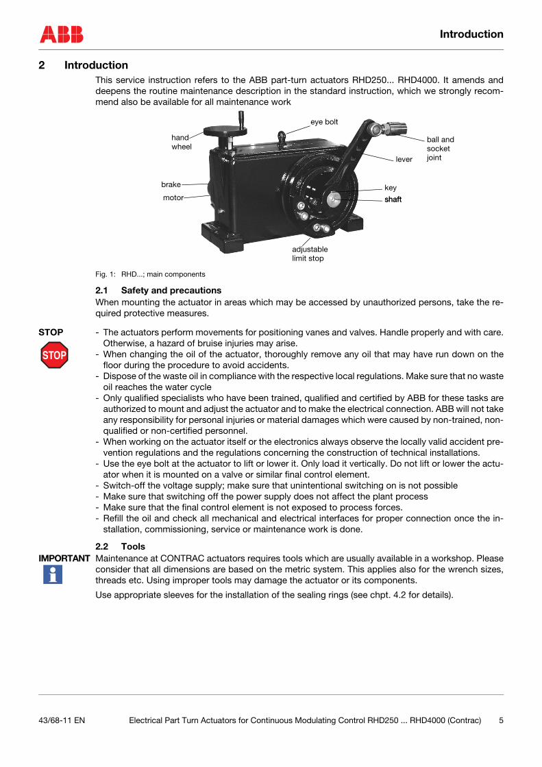
2 IntroductionThis service instruction refers to the ABB part-turn actuators RHD250... RHD4000. It amends anddeepens the routine maintenance description in the standard instruction, which we strongly recom-mend also be available for all maintenance work
Fig. 1: RHD...; main components
2.1 Safety and precautionsWhen mounting the actuator in areas which may be accessed by unauthorized persons, take the re-quired protective measures.
STOP
STOP - The actuators perform movements for positioning vanes and valves. Handle properly and with care.Otherwise, a hazard of bruise injuries may arise.
- When changing the oil of the actuator, thoroughly remove any oil that may have run down on thefloor during the procedure to avoid accidents.
- Dispose of the waste oil in compliance with the respective local regulations. Make sure that no wasteoil reaches the water cycle
- Only qualified specialists who have been trained, qualified and certified by ABB for these tasks areauthorized to mount and adjust the actuator and to make the electrical connection. ABB will not takeany responsibility for personal injuries or material damages which were caused by non-trained, non-qualified or non-certified personnel.
- When working on the actuator itself or the electronics always observe the locally valid accident pre-vention regulations and the regulations concerning the construction of technical installations.
- Use the eye bolt at the actuator to lift or lower it. Only load it vertically. Do not lift or lower the actu-ator when it is mounted on a valve or similar final control element.
- Switch-off the voltage supply; make sure that unintentional switching on is not possible- Make sure that switching off the power supply does not affect the plant process- Make sure that the final control element is not exposed to process forces.- Refill the oil and check all mechanical and electrical interfaces for proper connection once the in-
stallation, commissioning, service or maintenance work is done.
2.2 ToolsIMPORTANT Maintenance at CONTRAC actuators requires tools which are usually available in a workshop. Please
consider that all dimensions are based on the metric system. This applies also for the wrench sizes,threads etc. Using improper tools may damage the actuator or its components.
Use appropriate sleeves for the installation of the sealing rings (see chpt. 4.2 for details).
shaft
key
lever
handwheel
motor
adjustable
shaft
brake
limit stop
ball andsocketjoint
eye bolt
43/68-11 EN Electrical Part Turn Actuators for Continuous Modulating Control RHD250 ... RHD4000 (Contrac) 5
Lubrication
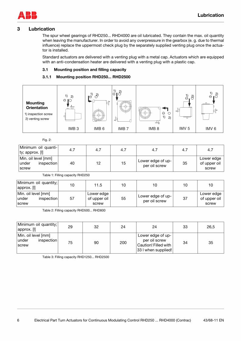
3 LubricationThe spur wheel gearings of RHD250... RHD4000 are oil lubricated. They contain the max. oil quantitywhen leaving the manufacturer. In order to avoid any overpressure in the gearbox (e. g. due to thermalinfluence) replace the uppermost check plug by the separately supplied venting plug once the actua-tor is installed.
Standard actuators are delivered with a venting plug with a metal cap. Actuators which are equippedwith an anti-condensation heater are delivered with a venting plug with a plastic cap.
3.1 Mounting position and filling capacity
3.1.1 Mounting position RHD250... RHD2500
Fig. 2:
Table 1: Filling capacity RHD250
Table 2: Filling capacity RHD500... RHD800
Table 3: Filling capacity RHD1250... RHD2500
IMB 3 IMB 6 IMB 7 IMB 8 IMV 5 IMV 6
1) 2)1) 2)
1) 2)
1) 2)
1) 2)1) 2)
MountingOrientation
1) inspection screw
2) venting screw
Minimum oil quanti-ty; approx. [l]
4.7 4.7 4.7 4.7 4.7 4.7
Min. oil level [mm]under inspectionscrew
40 12 15Lower edge of up-
per oil screw 35
Lower edge of upper oil
screw
Minimum oil quantity;approx. [l]
10 11.5 10 10 10 10
Min. oil level [mm]under inspectionscrew
57Lower edge of upper oil
screw55
Lower edge of up-per oil screw
37Lower edge of upper oil
screw
Minimum oil quantity;approx. [l]
29 32 24 24 33 26,5
Min. oil level [mm]under inspectionscrew
75 90 200
Lower edge of up-per oil screw
Caution! Filled with 33 l when supplied!
34 35
6 Electrical Part Turn Actuators for Continuous Modulating Control RHD250 ... RHD4000 (Contrac) 43/68-11 EN
Lubrication
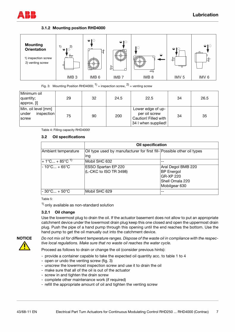
3.1.2 Mounting position RHD4000
Fig. 3: Mounting Position RHD4000; 1) = inspection screw, 2) = venting screw
Table 4: Filling capacity RHD4000!
3.2 Oil specifications
Table 5:
1) only available as non-standard solution
3.2.1 Oil changeUse the lowermost plug to drain the oil. If the actuator basement does not allow to put an appropriatecatchment device under the lowermost drain plug keep this one closed and open the uppermost drainplug. Push the pipe of a hand pump through this opening until the end reaches the bottom. Use thehand pump to get the oil manually out into the catchment device.
NOTICE Do not mix oil for different temperature ranges. Dispose of the waste oil in compliance with the respec-tive local regulations. Make sure that no waste oil reaches the water cycle.
Proceed as follows to drain or change the oil (consider previous hints):
- provide a container capable to take the expected oil quantity acc. to table 1 to 4- open or undo the venting screw (fig. 3)- unscrew the lowermost inspection screw and use it to drain the oil- make sure that all of the oil is out of the actuator- screw in and tighten the drain screw- complete other maintenance work (if required)- refill the appropriate amount of oil and tighten the venting screw
IMB 3 IMB 6 IMB 7 IMB 8 IMV 5 IMV 6
1) 2)
1) inspection screw
2) venting screw
MountingOrientation
Minimum oil quantity; approx. [l]
29 32 24.5 22.5 34 26.5
Min. oil level [mm]under inspectionscrew
75 90 200
Lower edge of up-per oil screw
Caution! Filled with 34 l when supplied!
34 35
Oil specification
Ambient temperature Oil type used by manufacturer for first fill-ing
Possible other oil types
+ 1°C... + 85°C 1) Mobil SHC 632 --- 10°C... + 65°C ESSO Spartan EP 220
(L-CKC to ISO TR 3498)Aral Degol BMB 220 BP EnergolGR-XP 220Shell Omala 220Mobilgear 630
- 30°C... + 50°C Mobil SHC 629 --
43/68-11 EN Electrical Part Turn Actuators for Continuous Modulating Control RHD250 ... RHD4000 (Contrac) 7
Maintenance
4 MaintenanceContrac actuators feature a robust construction. As a result, they are highly reliable and require onlylittle maintenance. The maintenance intervals depend upon the effective load.
The built-in microprocessor evaluates the actual load factors (e.g. torques, movements, temperatures,etc.) and derives the remaining operating time until the next routine maintenance is required. Use theconfiguration program for viewing this information.
CAUTION All maintenance work must be carried out by qualified specialists who have been trained for this task.Switch-off the power supply and protect the actuator against unintentional switch-on prior to anymaintenance. Make sure that disconnecting the power or any mechanical linkage does not endangerthe any process or person. Make sure that the actuator is not exposed to process forces during themaintenance work.
Apart from the load dependent maintenance intervals determined by the microprocessor we recom-mend routine maintenance; at least every 10 years.
The following description of the maintenance work provides that the actuator is disconnected fromthe damper and that all electrical supply is disconnected.
4.1 Lever
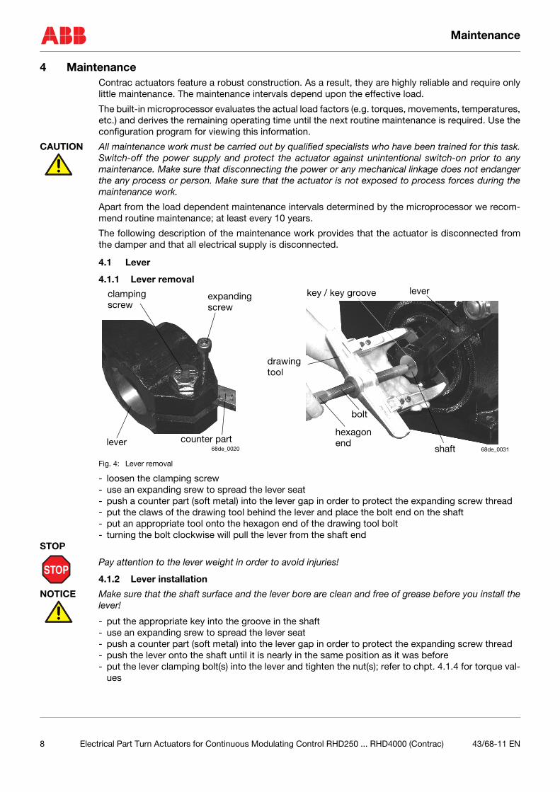
4.1.1 Lever removal
Fig. 4: Lever removal
- loosen the clamping screw- use an expanding srew to spread the lever seat- push a counter part (soft metal) into the lever gap in order to protect the expanding screw thread- put the claws of the drawing tool behind the lever and place the bolt end on the shaft- put an appropriate tool onto the hexagon end of the drawing tool bolt- turning the bolt clockwise will pull the lever from the shaft end
STOP
STOP
Pay attention to the lever weight in order to avoid injuries!
4.1.2 Lever installation
NOTICE Make sure that the shaft surface and the lever bore are clean and free of grease before you install thelever!
- put the appropriate key into the groove in the shaft- use an expanding srew to spread the lever seat- push a counter part (soft metal) into the lever gap in order to protect the expanding screw thread- push the lever onto the shaft until it is nearly in the same position as it was before- put the lever clamping bolt(s) into the lever and tighten the nut(s); refer to chpt. 4.1.4 for torque val-
ues
expanding
counter part
drawingtool
lever
bolt
shaft
hexagonend
lever
screwclampingscrew
key / key groove
68de_0020 68de_0031
8 Electrical Part Turn Actuators for Continuous Modulating Control RHD250 ... RHD4000 (Contrac) 43/68-11 EN
Maintenance
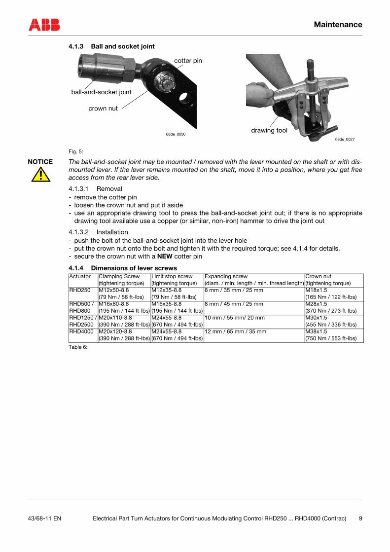
4.1.3 Ball and socket joint
Fig. 5:
NOTICE The ball-and-socket joint may be mounted / removed with the lever mounted on the shaft or with dis-mounted lever. If the lever remains mounted on the shaft, move it into a position, where you get freeaccess from the rear lever side.
4.1.3.1 Removal- remove the cotter pin- loosen the crown nut and put it aside- use an appropriate drawing tool to press the ball-and-socket joint out; if there is no appropriate
drawing tool available use a copper (or similar, non-iron) hammer to drive the joint out
4.1.3.2 Installation- push the bolt of the ball-and-socket joint into the lever hole- put the crown nut onto the bolt and tighten it with the required torque; see 4.1.4 for details.- secure the crown nut with a NEW cotter pin
4.1.4 Dimensions of lever screws
Table 6:
crown nut
ball-and-socket joint
cotter pin
drawing tool68de_0030
68de_0027
Actuator Clamping Screw(tightening torque)
Limit stop screw(tightening torque)
Expanding screw(diam. / min. length / min. thread length)
Crown nut(tightening torque)
RHD250 M12x50-8.8 (79 Nm / 58 ft-lbs)
M12x35-8.8(79 Nm / 58 ft-lbs)
8 mm / 35 mm / 25 mm M18x1.5(165 Nm / 122 ft-lbs)
RHD500 /RHD800
M16x80-8.8(195 Nm / 144 ft-lbs)
M16x35-8.8(195 Nm / 144 ft-lbs)
8 mm / 45 mm / 25 mm M28x1.5(370 Nm / 273 ft-lbs)
RHD1250 /RHD2500
M20x110-8.8(390 Nm / 288 ft-lbs)
M24x55-8.8(670 Nm / 494 ft-lbs)
10 mm / 55 mm/ 20 mm M30x1.5(455 Nm / 336 ft-lbs)
RHD4000 M20x120-8.8(390 Nm / 288 ft-lbs)
M24x55-8.8(670 Nm / 494 ft-lbs)
12 mm / 65 mm / 35 mm M38x1.5(750 Nm / 553 ft-lbs)
43/68-11 EN Electrical Part Turn Actuators for Continuous Modulating Control RHD250 ... RHD4000 (Contrac) 9
Maintenance
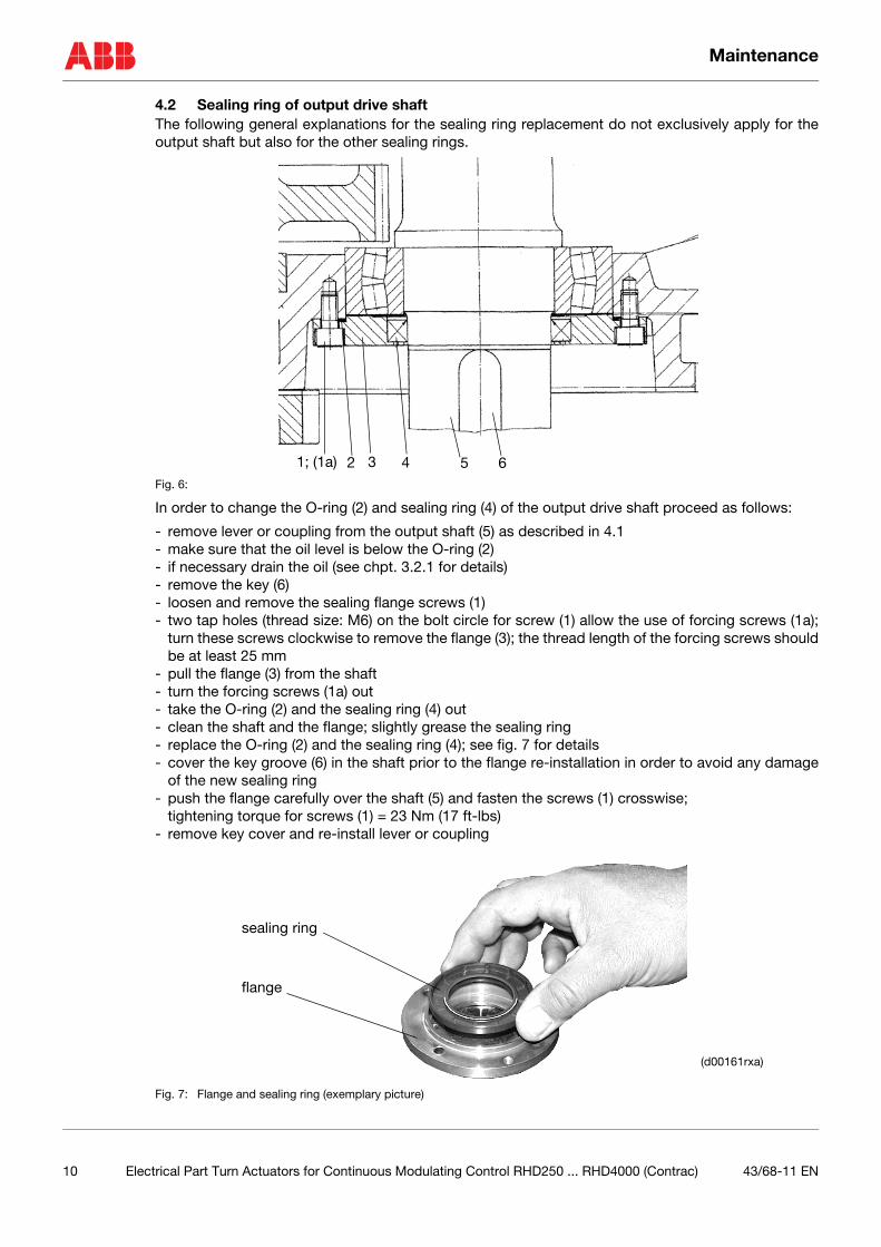
4.2 Sealing ring of output drive shaftThe following general explanations for the sealing ring replacement do not exclusively apply for theoutput shaft but also for the other sealing rings.
Fig. 6:
In order to change the O-ring (2) and sealing ring (4) of the output drive shaft proceed as follows:
- remove lever or coupling from the output shaft (5) as described in 4.1- make sure that the oil level is below the O-ring (2)- if necessary drain the oil (see chpt. 3.2.1 for details)- remove the key (6)- loosen and remove the sealing flange screws (1)- two tap holes (thread size: M6) on the bolt circle for screw (1) allow the use of forcing screws (1a);
turn these screws clockwise to remove the flange (3); the thread length of the forcing screws shouldbe at least 25 mm
- pull the flange (3) from the shaft- turn the forcing screws (1a) out- take the O-ring (2) and the sealing ring (4) out- clean the shaft and the flange; slightly grease the sealing ring- replace the O-ring (2) and the sealing ring (4); see fig. 7 for details- cover the key groove (6) in the shaft prior to the flange re-installation in order to avoid any damage
of the new sealing ring- push the flange carefully over the shaft (5) and fasten the screws (1) crosswise;
tightening torque for screws (1) = 23 Nm (17 ft-lbs)- remove key cover and re-install lever or coupling
Fig. 7: Flange and sealing ring (exemplary picture)
41; (1a) 2 3 5 6
sealing ring
flange
(d00161rxa)
10 Electrical Part Turn Actuators for Continuous Modulating Control RHD250 ... RHD4000 (Contrac) 43/68-11 EN
Maintenance
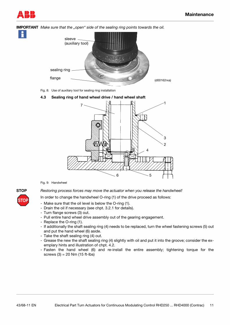
IMPORTANT Make sure that the „open“ side of the sealing ring points towards the oil.
Fig. 8: Use of auxiliary tool for sealing ring installation
4.3 Sealing ring of hand wheel drive / hand wheel shaft
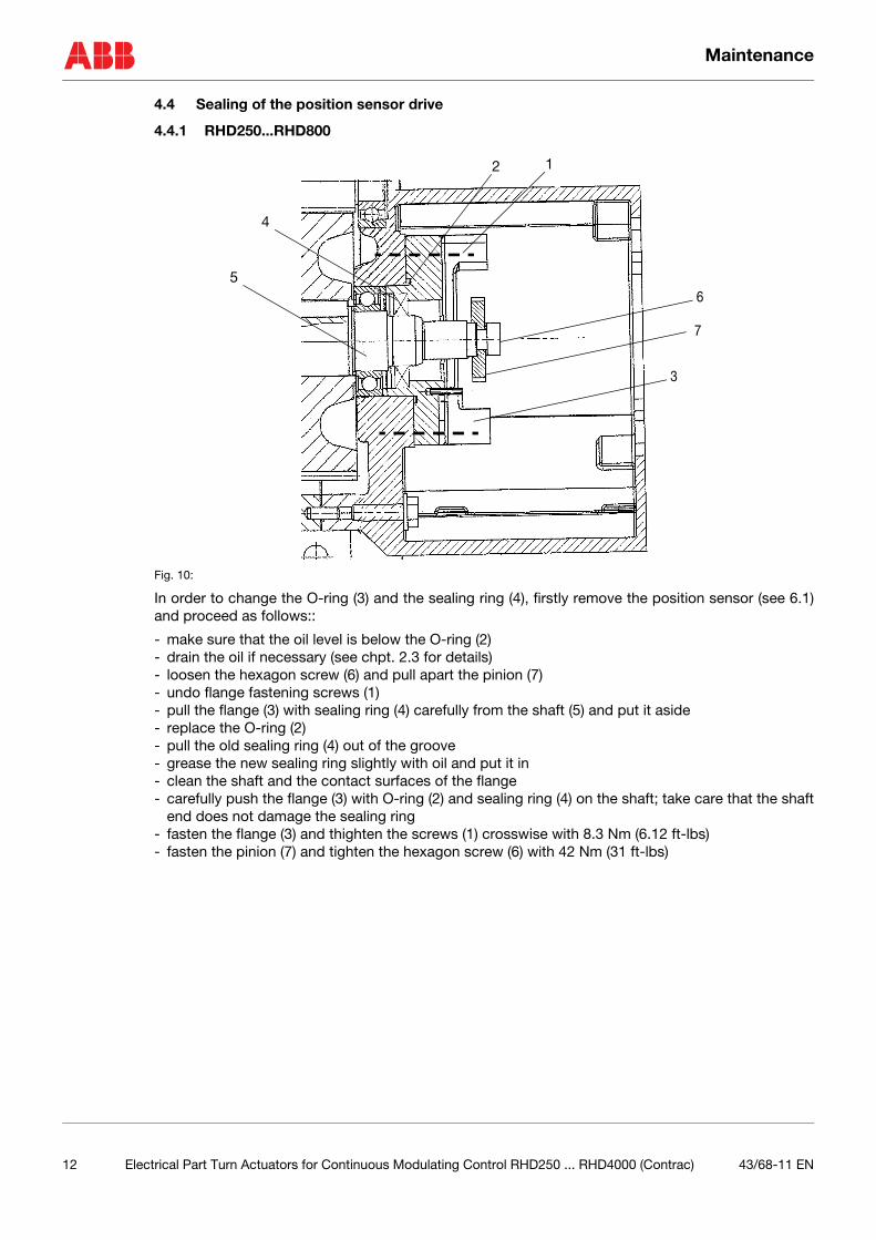
Fig. 9: Handwheel
STOP
STOP Restoring process forces may move the actuator when you release the handwheel!
In order to change the handwheel O-ring (1) of the drive proceed as follows:
- Make sure that the oil level is below the O-ring (1).- Drain the oil if necessary (see chpt. 3.2.1 for details).- Turn flange screws (3) out.- Pull entire hand wheel drive assembly out of the gearing engagement.- Replace the O-ring (1).- If additionally the shaft sealing ring (4) needs to be replaced, turn the wheel fastening screws (5) out
and put the hand wheel (6) aside.- Take the shaft sealing ring (4) out.- Grease the new the shaft sealing ring (4) slightly with oil and put it into the groove; consider the ex-
emplary hints and illustration of chpt. 4.2.- Fasten the hand wheel (6) and re-install the entire assembly; tightening torque for the
screws (3) = 20 Nm (15 ft-lbs)
sleeve
sealing ring
flange(d00162rxa)
(auxiliary tool)
1
3
2
5
4
6
7
43/68-11 EN Electrical Part Turn Actuators for Continuous Modulating Control RHD250 ... RHD4000 (Contrac) 11
Maintenance
4.4 Sealing of the position sensor drive
4.4.1 RHD250...RHD800
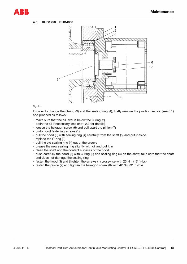
Fig. 10:
In order to change the O-ring (3) and the sealing ring (4), firstly remove the position sensor (see 6.1)and proceed as follows::
- make sure that the oil level is below the O-ring (2)- drain the oil if necessary (see chpt. 2.3 for details)- loosen the hexagon screw (6) and pull apart the pinion (7)- undo flange fastening screws (1)- pull the flange (3) with sealing ring (4) carefully from the shaft (5) and put it aside- replace the O-ring (2)- pull the old sealing ring (4) out of the groove - grease the new sealing ring slightly with oil and put it in- clean the shaft and the contact surfaces of the flange- carefully push the flange (3) with O-ring (2) and sealing ring (4) on the shaft; take care that the shaft
end does not damage the sealing ring- fasten the flange (3) and thighten the screws (1) crosswise with 8.3 Nm (6.12 ft-lbs)- fasten the pinion (7) and tighten the hexagon screw (6) with 42 Nm (31 ft-lbs)
2 1
3
4
6
7
5
12 Electrical Part Turn Actuators for Continuous Modulating Control RHD250 ... RHD4000 (Contrac) 43/68-11 EN
Maintenance
4.5 RHD1250... RHD4000
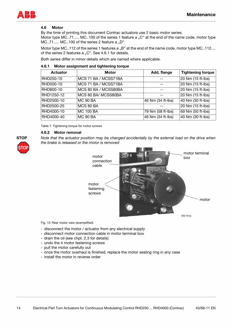
Fig. 11:
In order to change the O-ring (3) and the sealing ring (4), firstly remove the position sensor (see 6.1)and proceed as follows:
- make sure that the oil level is below the O-ring (2)- drain the oil if necessary (see chpt. 2.3 for details)- loosen the hexagon screw (6) and pull apart the pinion (7)- undo hood fastening screws (1)- pull the hood (3) with sealing ring (4) carefully from the shaft (5) and put it aside- replace the O-ring (2)- pull the old sealing ring (4) out of the groove - grease the new sealing ring slightly with oil and put it in- clean the shaft and the contact surfaces of the hood- push carefully the hood (3) with O-ring (2) and sealing ring (4) on the shaft; take care that the shaft
end does not damage the sealing ring- fasten the hood (3) and thighten the screws (1) crosswise with 23 Nm (17 ft-lbs)- fasten the pinion (7) and tighten the hexagon screw (6) with 42 Nm (31 ft-lbs)
1
3
4
2
6
5
7
43/68-11 EN Electrical Part Turn Actuators for Continuous Modulating Control RHD250 ... RHD4000 (Contrac) 13
Maintenance
4.6 MotorBy the time of printing this document Contrac actuators use 2 basic motor series. Motor type MC..71..... MC..100 of the series 1 feature a „C“ at the end of the name code, motor typeMC..71..... MC..100 of the series 2 feature a „D“.
Motor type MC..112 of the series 1 features a „B“ at the end of the name code, motor type MC..112....of the series 2 features a „C“. See 4.6.1 for details.
Both series differ in minor details which are named where applicable.
4.6.1 Motor assignment and tightening torque
Table 7: Tightening torque for motor screws
4.6.2 Motor removal
STOP
STOP Note that the actuator position may be changed accidentally by the external load on the drive whenthe brake is released or the motor is removed
Fig. 12: Rear motor view (exemplified)
- disconnect the motor / actuator from any electrical supply- disconnect motor connection cable in motor terminal box- drain the oil (see chpt. 2.3 for details)- undo the 4 motor fastening screws- pull the motor carefully out- once the motor overhaul is finished, replace the motor sealing ring in any case- install the motor in reverse order
Actuator Motor Add. flange Tightening torque
RHD250-10 MCS 71 BA / MCSS71BA -- 20 Nm (15 ft-lbs)RHD500-10 MCS 71 BA / MCSS71BA -- 20 Nm (15 ft-lbs)RHD800-10 MCS 80 BA / MCSS80BA -- 20 Nm (15 ft-lbs)RHD1250-12 MCS 80 BA/ MCSS80BA -- 20 Nm (15 ft-lbs)RHD2500-10 MC 90 BA 46 Nm (34 ft-lbs) 40 Nm (30 ft-lbs)RHD2500-25 MCS 80 BA -- 20 Nm (15 ft-lbs)RHD4000-10 MC 100 BA 79 Nm (58 ft-lbs) 69 Nm (50 ft-lbs)RHD4000-40 MC 90 BA 46 Nm (34 ft-lbs) 40 Nm (30 ft-lbs)
motor
motor fastening
motor terminalboxmotor
connectioncable
d0214rxa
screws
14 Electrical Part Turn Actuators for Continuous Modulating Control RHD250 ... RHD4000 (Contrac) 43/68-11 EN
Maintenance
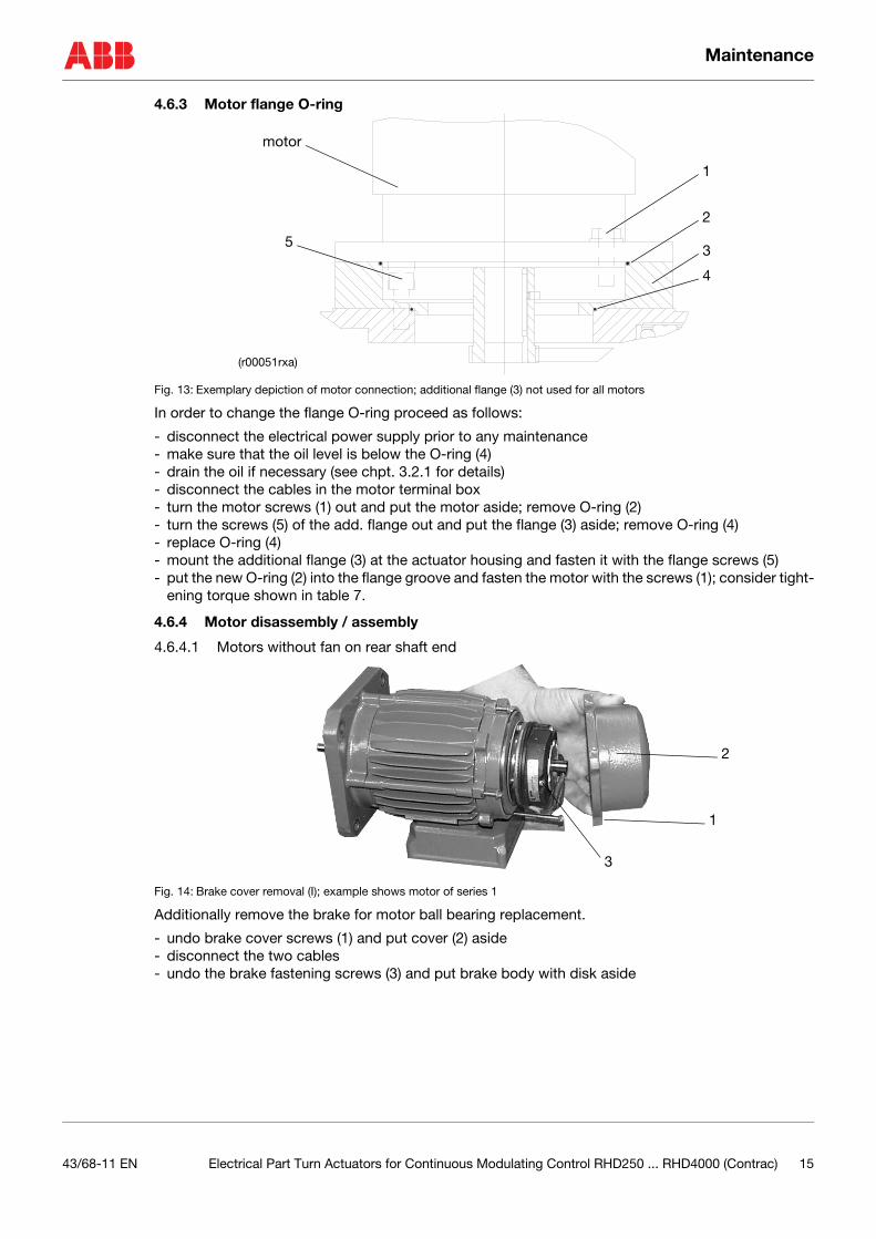
4.6.3 Motor flange O-ring
Fig. 13: Exemplary depiction of motor connection; additional flange (3) not used for all motors
In order to change the flange O-ring proceed as follows:
- disconnect the electrical power supply prior to any maintenance- make sure that the oil level is below the O-ring (4)- drain the oil if necessary (see chpt. 3.2.1 for details)- disconnect the cables in the motor terminal box- turn the motor screws (1) out and put the motor aside; remove O-ring (2)- turn the screws (5) of the add. flange out and put the flange (3) aside; remove O-ring (4)- replace O-ring (4)- mount the additional flange (3) at the actuator housing and fasten it with the flange screws (5)- put the new O-ring (2) into the flange groove and fasten the motor with the screws (1); consider tight-
ening torque shown in table 7.
4.6.4 Motor disassembly / assembly
4.6.4.1 Motors without fan on rear shaft end
Fig. 14: Brake cover removal (I); example shows motor of series 1
Additionally remove the brake for motor ball bearing replacement.
- undo brake cover screws (1) and put cover (2) aside- disconnect the two cables- undo the brake fastening screws (3) and put brake body with disk aside
1
motor
2
3
4
5
(r00051rxa)
1
2
3
43/68-11 EN Electrical Part Turn Actuators for Continuous Modulating Control RHD250 ... RHD4000 (Contrac) 15
Maintenance
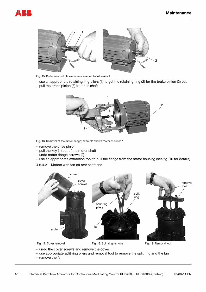
Fig. 15: Brake removal (II); example shows motor of series 1
- use an appropriate retaining ring pliers (1) to get the retaining ring (2) for the brake pinion (3) out- pull the brake pinion (3) from the shaft
Fig. 16: Removal of the motor flange; example shows motor of series 1
- remove the drive pinion- pull the key (1) out of the motor shaft- undo motor flange screws (2)- use an appropriate extraction tool to pull the flange from the stator housing (see fig. 16 for details)
4.6.4.2 Motors with fan on rear shaft end
- undo the cover screws and remove the cover- use appropriate split ring pliers and removal tool to remove the split ring and the fan- remove the fan
Fig. 17: Cover removal Fig. 18: Split ring removal Fig. 19: Removal tool
123
3
2
1
3
cover
cover
motor
screws
split ring
split
fan
ring
pliers
removaltool
16 Electrical Part Turn Actuators for Continuous Modulating Control RHD250 ... RHD4000 (Contrac) 43/68-11 EN
Maintenance
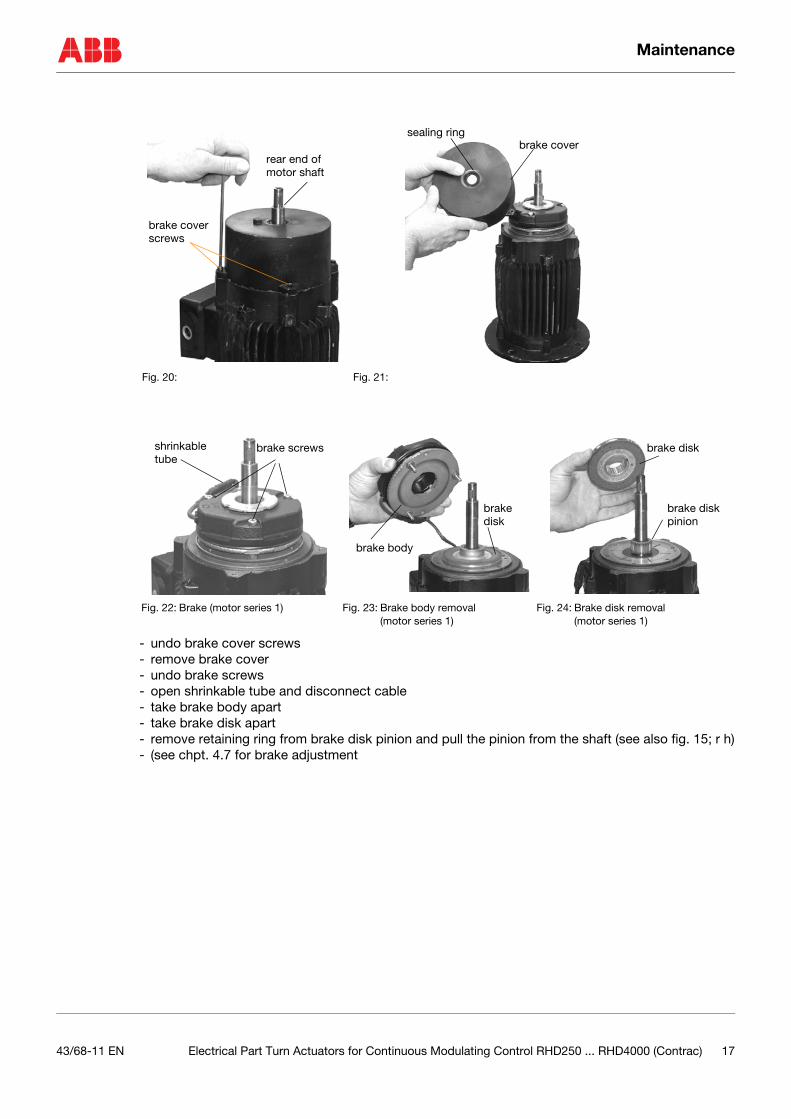
- undo brake cover screws- remove brake cover- undo brake screws- open shrinkable tube and disconnect cable- take brake body apart- take brake disk apart- remove retaining ring from brake disk pinion and pull the pinion from the shaft (see also fig. 15; r h)- (see chpt. 4.7 for brake adjustment
Fig. 20: Fig. 21:
Fig. 22: Brake (motor series 1) Fig. 23: Brake body removal (motor series 1)
Fig. 24: Brake disk removal (motor series 1)
brake coverscrews
rear end of motor shaft
brake coversealing ring
brake screwsshrinkabletube
brake body
brake disk
brake disk
brake disk pinion
43/68-11 EN Electrical Part Turn Actuators for Continuous Modulating Control RHD250 ... RHD4000 (Contrac) 17
Maintenance
)
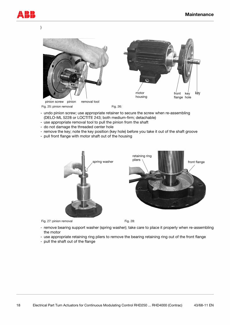
- undo pinion screw; use appropriate retainer to secure the screw when re-assembling (DELO-ML 5228 or LOCTITE 243; both medium-firm; detachable)
- use appropriate removal tool to pull the pinion from the shaft- do not damage the threaded center hole- remove the key; note the key position (key hole) before you take it out of the shaft groove- pull front flange with motor shaft out of the housing
- remove bearing support washer (spring washer); take care to place it properly when re-assemblingthe motor
- use appropriate retaining ring pliers to remove the bearing retaining ring out of the front flange- pull the shaft out of the flange
Fig. 25: pinion removal Fig. 26:
Fig. 27: pinion removal Fig. 28:
pinion screw pinion removal tool
keykeyhole
frontflange
motorhousing
spring washer
retaining ringpliers
front flange
18 Electrical Part Turn Actuators for Continuous Modulating Control RHD250 ... RHD4000 (Contrac) 43/68-11 EN
Maintenance
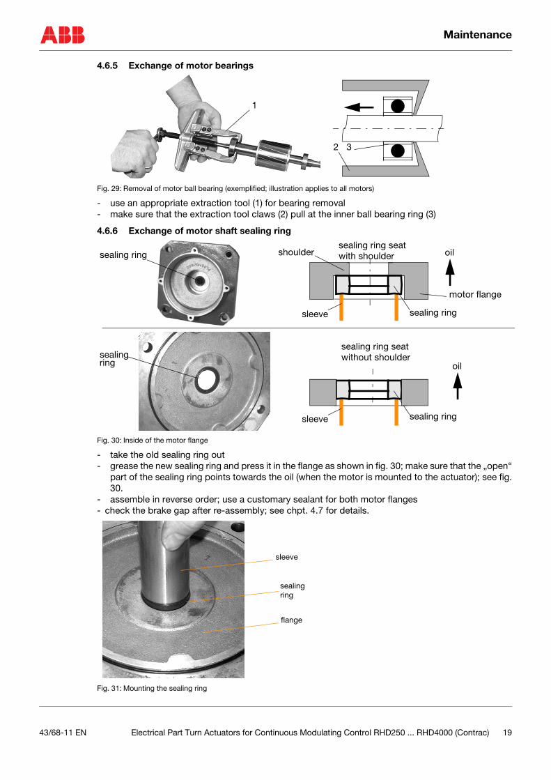
4.6.5 Exchange of motor bearings
Fig. 29: Removal of motor ball bearing (exemplified; illustration applies to all motors)
- use an appropriate extraction tool (1) for bearing removal- make sure that the extraction tool claws (2) pull at the inner ball bearing ring (3)
4.6.6 Exchange of motor shaft sealing ring
Fig. 30: Inside of the motor flange
- take the old sealing ring out- grease the new sealing ring and press it in the flange as shown in fig. 30; make sure that the „open“
part of the sealing ring points towards the oil (when the motor is mounted to the actuator); see fig.30.
- assemble in reverse order; use a customary sealant for both motor flanges- check the brake gap after re-assembly; see chpt. 4.7 for details.
Fig. 31: Mounting the sealing ring
1
2 3
sealing ring
sleeve
motor flange
sealing ring
oil
sleeve sealing ring
sealing ring seatwith shoulder
sealing ring seatwithout shoulder
shoulder
sealing ring oil
sealing ring
sleeve
flange
43/68-11 EN Electrical Part Turn Actuators for Continuous Modulating Control RHD250 ... RHD4000 (Contrac) 19
Maintenance
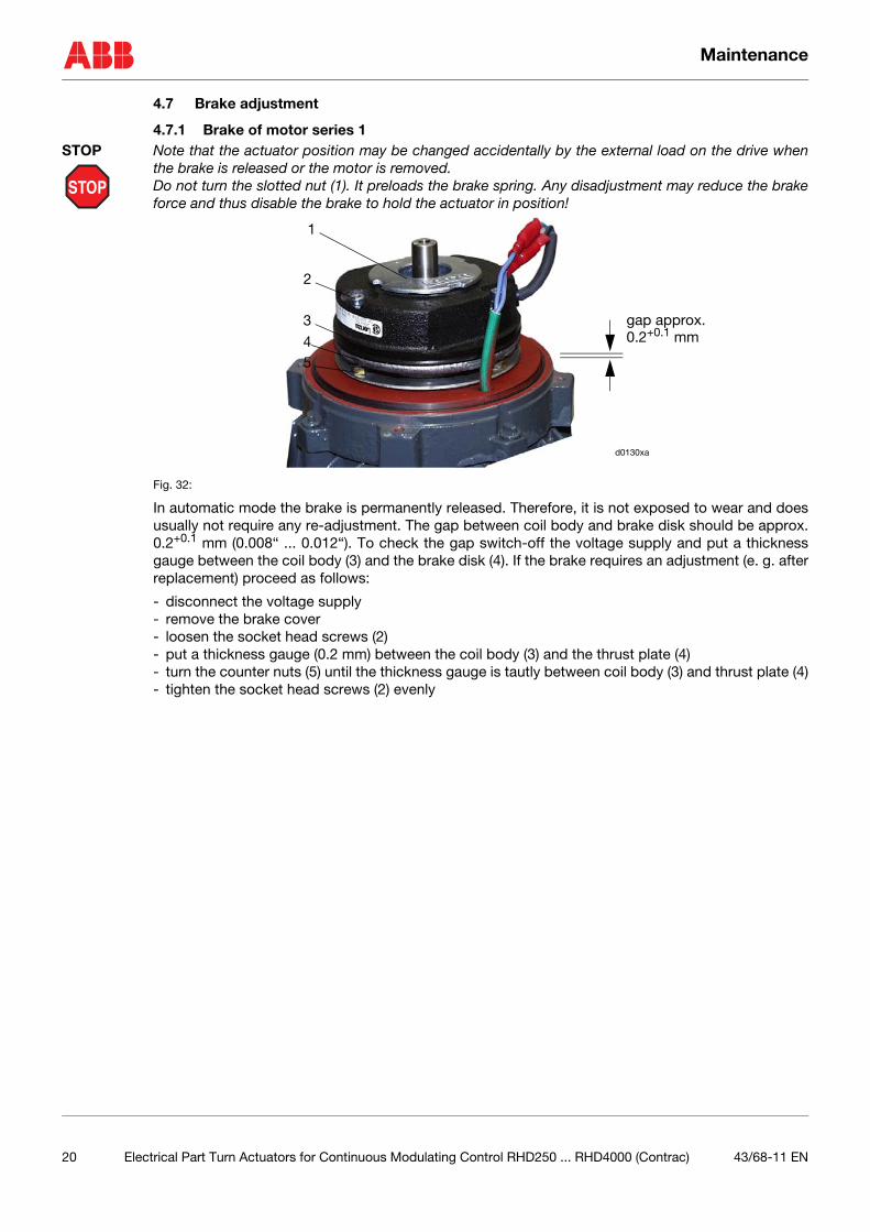
4.7 Brake adjustment
4.7.1 Brake of motor series 1
STOP
STOP Note that the actuator position may be changed accidentally by the external load on the drive whenthe brake is released or the motor is removed.Do not turn the slotted nut (1). It preloads the brake spring. Any disadjustment may reduce the brakeforce and thus disable the brake to hold the actuator in position!
Fig. 32:
In automatic mode the brake is permanently released. Therefore, it is not exposed to wear and doesusually not require any re-adjustment. The gap between coil body and brake disk should be approx.0.2+0.1 mm (0.008“ ... 0.012“). To check the gap switch-off the voltage supply and put a thicknessgauge between the coil body (3) and the brake disk (4). If the brake requires an adjustment (e. g. afterreplacement) proceed as follows:
- disconnect the voltage supply- remove the brake cover- loosen the socket head screws (2)- put a thickness gauge (0.2 mm) between the coil body (3) and the thrust plate (4)- turn the counter nuts (5) until the thickness gauge is tautly between coil body (3) and thrust plate (4)- tighten the socket head screws (2) evenly
1
gap approx. 0.2+0.1 mm
2
3
54
d0130xa
20 Electrical Part Turn Actuators for Continuous Modulating Control RHD250 ... RHD4000 (Contrac) 43/68-11 EN
Maintenance
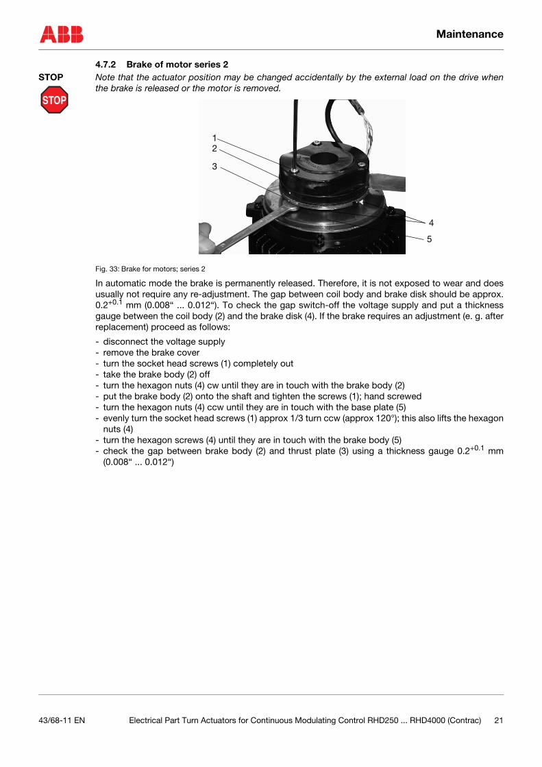
4.7.2 Brake of motor series 2
STOP
STOP Note that the actuator position may be changed accidentally by the external load on the drive whenthe brake is released or the motor is removed.
Fig. 33: Brake for motors; series 2
In automatic mode the brake is permanently released. Therefore, it is not exposed to wear and doesusually not require any re-adjustment. The gap between coil body and brake disk should be approx.0.2+0.1 mm (0.008“ ... 0.012“). To check the gap switch-off the voltage supply and put a thicknessgauge between the coil body (2) and the brake disk (4). If the brake requires an adjustment (e. g. afterreplacement) proceed as follows:
- disconnect the voltage supply- remove the brake cover- turn the socket head screws (1) completely out- take the brake body (2) off- turn the hexagon nuts (4) cw until they are in touch with the brake body (2)- put the brake body (2) onto the shaft and tighten the screws (1); hand screwed- turn the hexagon nuts (4) ccw until they are in touch with the base plate (5)- evenly turn the socket head screws (1) approx 1/3 turn ccw (approx 120°); this also lifts the hexagon
nuts (4)- turn the hexagon screws (4) until they are in touch with the brake body (5)- check the gap between brake body (2) and thrust plate (3) using a thickness gauge 0.2+0.1 mm
(0.008“ ... 0.012“)
21
3
4
5
43/68-11 EN Electrical Part Turn Actuators for Continuous Modulating Control RHD250 ... RHD4000 (Contrac) 21
Electrical Connection
5 Electrical Connection
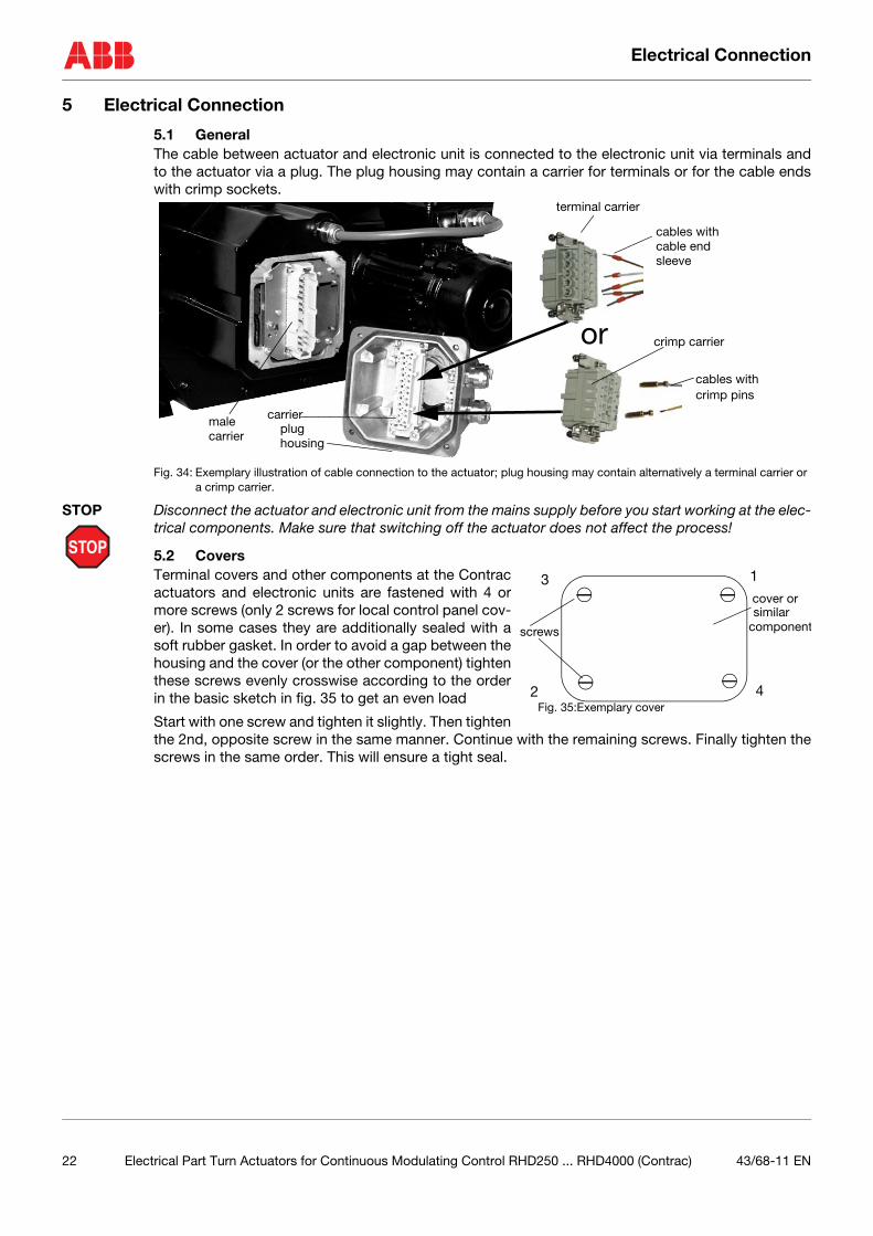
5.1 GeneralThe cable between actuator and electronic unit is connected to the electronic unit via terminals andto the actuator via a plug. The plug housing may contain a carrier for terminals or for the cable endswith crimp sockets.
Fig. 34: Exemplary illustration of cable connection to the actuator; plug housing may contain alternatively a terminal carrier or a crimp carrier.
STOP
STOP Disconnect the actuator and electronic unit from the mains supply before you start working at the elec-trical components. Make sure that switching off the actuator does not affect the process!
5.2 CoversTerminal covers and other components at the Contracactuators and electronic units are fastened with 4 ormore screws (only 2 screws for local control panel cov-er). In some cases they are additionally sealed with asoft rubber gasket. In order to avoid a gap between thehousing and the cover (or the other component) tightenthese screws evenly crosswise according to the orderin the basic sketch in fig. 35 to get an even load
Start with one screw and tighten it slightly. Then tightenthe 2nd, opposite screw in the same manner. Continue with the remaining screws. Finally tighten thescrews in the same order. This will ensure a tight seal.
terminal carrier
crimp carrier
cables with cable end sleeve
cables with crimp pins
carrierplug male
or
carrier housing
1
2
3
4
cover or similar
screws
Fig. 35:Exemplary cover
component
22 Electrical Part Turn Actuators for Continuous Modulating Control RHD250 ... RHD4000 (Contrac) 43/68-11 EN
Electrical Connection
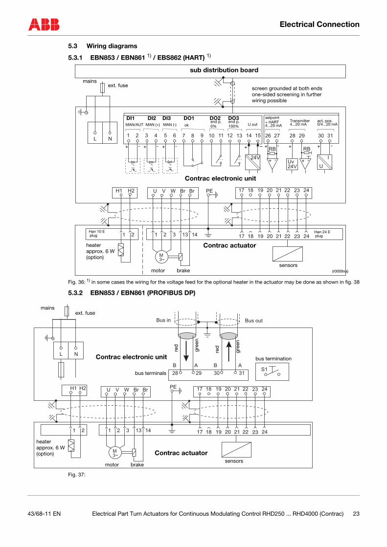
5.3 Wiring diagrams
5.3.1 EBN853 / EBN861 1) / EBS862 (HART) 1)
Fig. 36: 1) in some cases the wiring for the voltage feed for the optional heater in the actuator may be done as shown in fig. 38
5.3.2 EBN853 / EBN861 (PROFIBUS DP)
Fig. 37:
24V
30
+ - -+
RB
+ -
31
I
U
26 271
+ - + - + - + -
72 83 94 10 135 11 146 12 15L N
17 18 19 20 21 22 23 241 21 2 3 13 14
M
3~
17 18 19 20 21 22 23 24U V W Br Br PEH1 H2
Uv
24V
+
RB
+ -
28 29
sub distribution board
screen grounded at both endsone-sided screening in furtherwiring possible
ext. fusemains
Contrac electronic unit
Contrac actuator
Han 24 Eplug
Han 10 Eplug
sensors
heaterapprox. 6 W(option)
motor brake (r0009xa)
setpoint
4...20 mA+ HART 4...20 mA
Transmitter0/4...20 mAact. pos.
MAN/AUT MAN (+) MAN (-) okend p. end p.
100%0% U out
DI1 DI2 DI3 DO1 DO2 DO3
L N
Bus outBus in
28 29 30
B BA A
31S1
17 18 19 20 21 22 23 24U V W BrH1 BrH2
17 18 19 20 21 22 23 241 2 3 13 14
M
3~
PE
1 2
ext. fusemains
bus termination
bus terminals
heaterapprox. 6 W(option) Contrac actuator
Contrac electronic unit
red
gree
n
red
gree
n
sensorsmotor brake
43/68-11 EN Electrical Part Turn Actuators for Continuous Modulating Control RHD250 ... RHD4000 (Contrac) 23
Electrical Connection
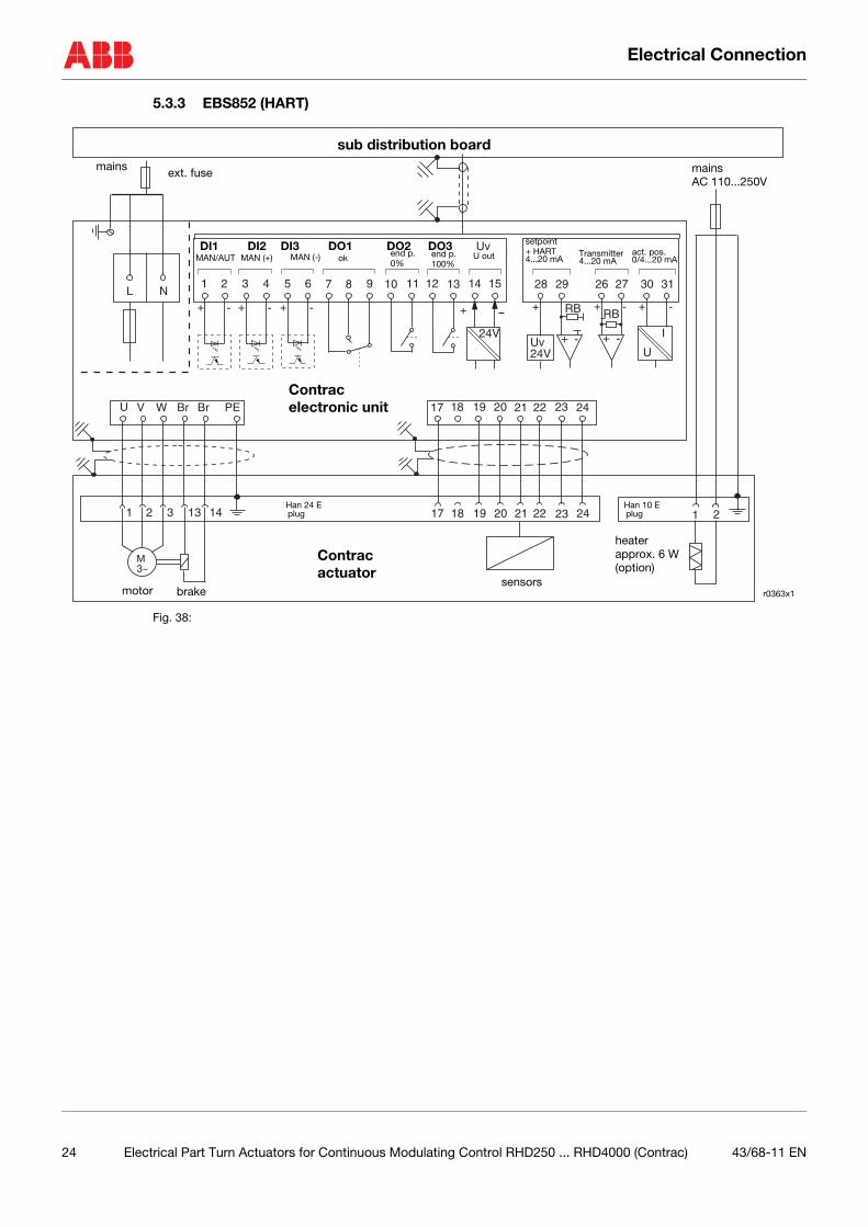
5.3.3 EBS852 (HART)
Fig. 38:
24V
Uv
30+ - -+
RB
+ -
31
I
U
26 271
+ - + - + - + -
72 83 94 10 135 11 146 12 15L N
U V W Br Br PE 17 18 19 20 21 22 23 24
17 18 19 20 21 22 23 241 2 3 13 14
M3~
Uv24V
+RB
+ -
28 29
1 2
r0363x1
Contrac
mainsAC 110...250V
sub distribution board
electronic unit
Contrac actuator
heaterapprox. 6 W(option)
sensorsmotor brake
Han 24 Eplug
Han 10 Eplug
mains ext. fuse
setpoint
4...20 mA+ HART
4...20 mATransmitter
0/4...20 mAact. pos.
MAN/AUT MAN (+) MAN (-) ok end p. end p.100%0%
U outDI1 DI2 DI3 DO1 DO2 DO3
24 Electrical Part Turn Actuators for Continuous Modulating Control RHD250 ... RHD4000 (Contrac) 43/68-11 EN
Electrical Connection
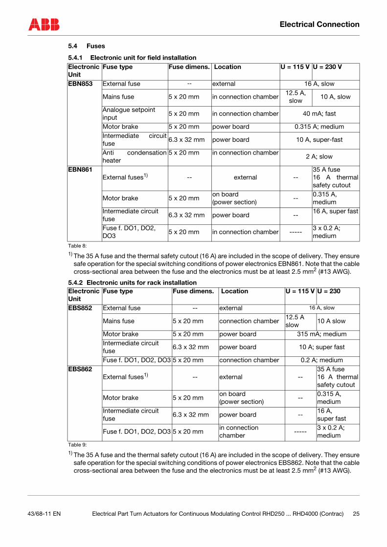
5.4 Fuses
5.4.1 Electronic unit for field installation
Table 8:
1) The 35 A fuse and the thermal safety cutout (16 A) are included in the scope of delivery. They ensuresafe operation for the special switching conditions of power electronics EBN861. Note that the cablecross-sectional area between the fuse and the electronics must be at least 2.5 mm2 (#13 AWG).
5.4.2 Electronic units for rack installation
Table 9:
1) The 35 A fuse and the thermal safety cutout (16 A) are included in the scope of delivery. They ensuresafe operation for the special switching conditions of power electronics EBS862. Note that the cablecross-sectional area between the fuse and the electronics must be at least 2.5 mm2 (#13 AWG).
ElectronicUnit
Fuse type Fuse dimens. Location U = 115 V U = 230 V
EBN853 External fuse -- external 16 A, slow
Mains fuse 5 x 20 mm in connection chamber12.5 A, slow
10 A, slow
Analogue setpoint input
5 x 20 mm in connection chamber 40 mA; fast
Motor brake 5 x 20 mm power board 0.315 A; mediumIntermediate circuitfuse
6.3 x 32 mm power board 10 A, super-fast
Anti condensationheater
5 x 20 mm in connection chamber2 A; slow
EBN861 External fuses1) -- external --
35 A fuse16 A thermalsafety cutout
Motor brake 5 x 20 mmon board (power section)
--0.315 A, medium
Intermediate circuit fuse
6.3 x 32 mm power board --16 A, super fast
Fuse f. DO1, DO2, DO3
5 x 20 mm in connection chamber -----3 x 0.2 A;medium
ElectronicUnit
Fuse type Fuse dimens. Location U = 115 V U = 230
EBS852 External fuse -- external 16 A, slow
Mains fuse 5 x 20 mm connection chamber12.5 Aslow
10 A slow
Motor brake 5 x 20 mm power board 315 mA; mediumIntermediate circuit fuse
6.3 x 32 mm power board 10 A; super fast
Fuse f. DO1, DO2, DO3 5 x 20 mm connection chamber 0.2 A; mediumEBS862
External fuses1) -- external --35 A fuse16 A thermalsafety cutout
Motor brake 5 x 20 mmon board (power section)
--0.315 A, medium
Intermediate circuit fuse
6.3 x 32 mm power board --16 A, super fast
Fuse f. DO1, DO2, DO3 5 x 20 mmin connection chamber
-----3 x 0.2 A;medium
43/68-11 EN Electrical Part Turn Actuators for Continuous Modulating Control RHD250 ... RHD4000 (Contrac) 25
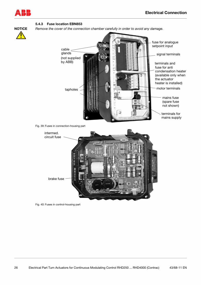
Electrical Connection
5.4.3 Fuse location EBN853NOTICE Remove the cover of the connection chamber carefully in order to avoid any damage.
Fig. 39: Fuses in connection-housing part
Fig. 40: Fuses in control-housing part
tapholes
signal terminals
motor terminals
terminals for
mains fuse
fuse for anti
fuse for analogue setpoint input
cable
condensation heater
mains supply
glands
terminals and
(available only whenthe actuator
(not supplied by ABB)
(spare fusenot shown)
heater is installed)
intermed.
brake fuse
circuit fuse
26 Electrical Part Turn Actuators for Continuous Modulating Control RHD250 ... RHD4000 (Contrac) 43/68-11 EN
Electrical Connection
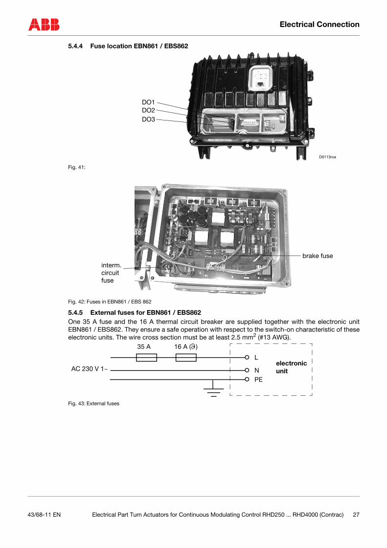
5.4.4 Fuse location EBN861 / EBS862
Fig. 41:
Fig. 42: Fuses in EBN861 / EBS 862
5.4.5 External fuses for EBN861 / EBS862One 35 A fuse and the 16 A thermal circuit breaker are supplied together with the electronic unitEBN861 / EBS862. They ensure a safe operation with respect to the switch-on characteristic of theseelectronic units. The wire cross section must be at least 2.5 mm2 (#13 AWG).
Fig. 43: External fuses
DO1DO2DO3
D0113rxa
brake fuseinterm.circuitfuse
L
AC 230 V 1~
16 A (ϑ)35 A
NPE
electronic unit
43/68-11 EN Electrical Part Turn Actuators for Continuous Modulating Control RHD250 ... RHD4000 (Contrac) 27
Electrical Connection
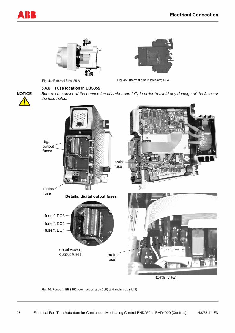
5.4.6 Fuse location in EBS852NOTICE Remove the cover of the connection chamber carefully in order to avoid any damage of the fuses or
the fuse holder.
Fig. 46: Fuses in EBS852; connection area (left) and main pcb (right)
Fig. 44: External fuse; 35 A Fig. 45: Thermal circuit breaker; 16 A
dig. output
mains
brake
brake
(detail view)
fuse
fuses
fuse
fuse
fuse f. DO1
fuse f. DO2
fuse f. DO3
detail view of output fuses
Details: digital output fuses
28 Electrical Part Turn Actuators for Continuous Modulating Control RHD250 ... RHD4000 (Contrac) 43/68-11 EN
Exchange of position sensor
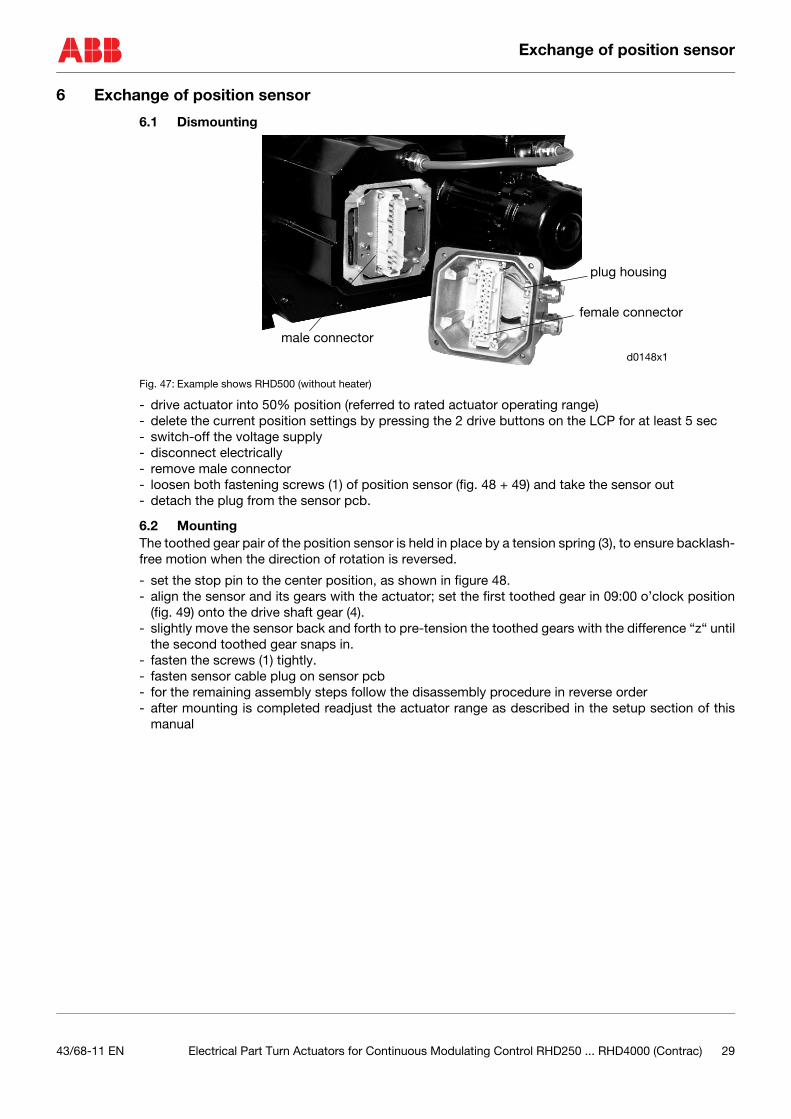
6 Exchange of position sensor
6.1 Dismounting
Fig. 47: Example shows RHD500 (without heater)
- drive actuator into 50% position (referred to rated actuator operating range)- delete the current position settings by pressing the 2 drive buttons on the LCP for at least 5 sec- switch-off the voltage supply- disconnect electrically- remove male connector- loosen both fastening screws (1) of position sensor (fig. 48 + 49) and take the sensor out- detach the plug from the sensor pcb.
6.2 MountingThe toothed gear pair of the position sensor is held in place by a tension spring (3), to ensure backlash-free motion when the direction of rotation is reversed.
- set the stop pin to the center position, as shown in figure 48. - align the sensor and its gears with the actuator; set the first toothed gear in 09:00 o’clock position
(fig. 49) onto the drive shaft gear (4). - slightly move the sensor back and forth to pre-tension the toothed gears with the difference “z“ until
the second toothed gear snaps in. - fasten the screws (1) tightly.- fasten sensor cable plug on sensor pcb- for the remaining assembly steps follow the disassembly procedure in reverse order- after mounting is completed readjust the actuator range as described in the setup section of this
manual
male connector
plug housing
d0148x1
female connector
43/68-11 EN Electrical Part Turn Actuators for Continuous Modulating Control RHD250 ... RHD4000 (Contrac) 29
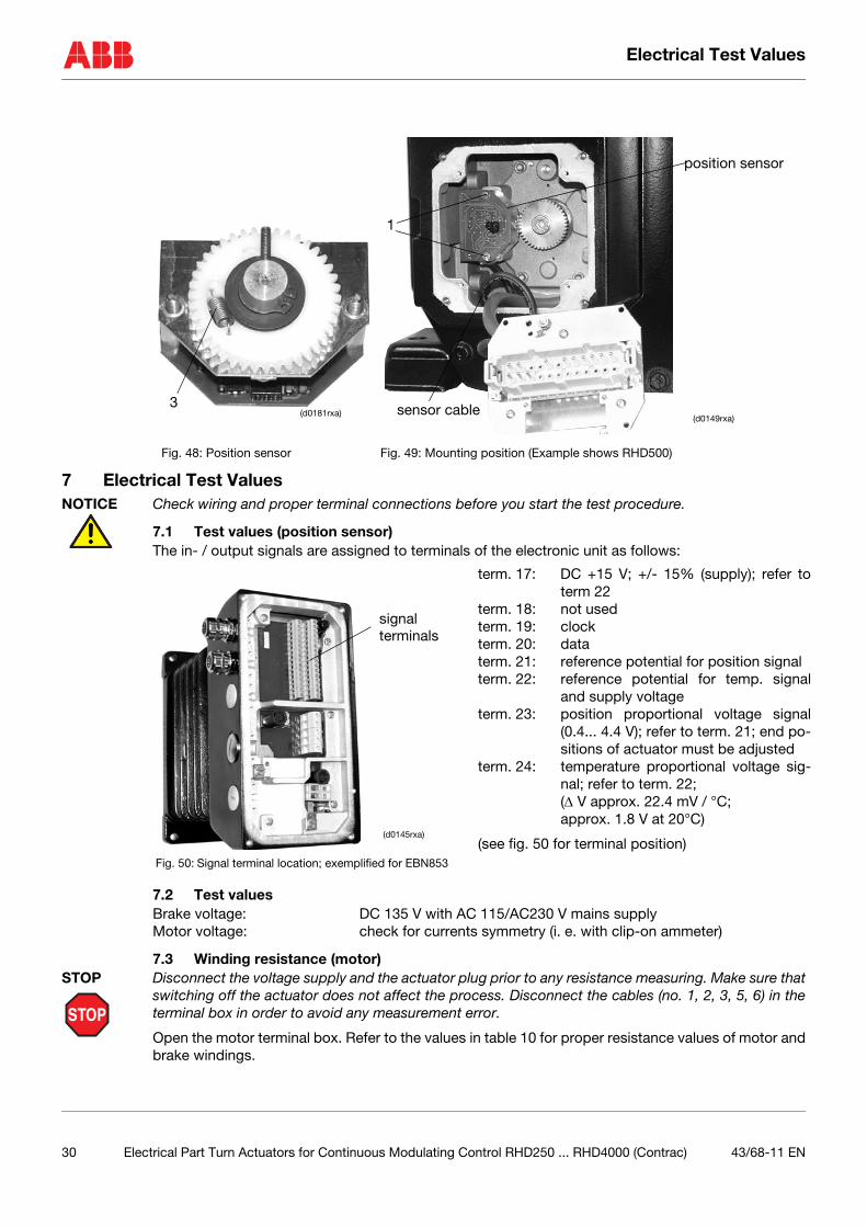
Electrical Test Values
7 Electrical Test ValuesNOTICE Check wiring and proper terminal connections before you start the test procedure.
7.1 Test values (position sensor)The in- / output signals are assigned to terminals of the electronic unit as follows:
7.2 Test valuesBrake voltage: DC 135 V with AC 115/AC230 V mains supplyMotor voltage: check for currents symmetry (i. e. with clip-on ammeter)
7.3 Winding resistance (motor)
STOP
STOP Disconnect the voltage supply and the actuator plug prior to any resistance measuring. Make sure thatswitching off the actuator does not affect the process. Disconnect the cables (no. 1, 2, 3, 5, 6) in theterminal box in order to avoid any measurement error.
Open the motor terminal box. Refer to the values in table 10 for proper resistance values of motor andbrake windings.
Fig. 48: Position sensor Fig. 49: Mounting position (Example shows RHD500)
(d0181rxa)3
position sensor
1
sensor cable(d0149rxa)
term. 17: DC +15 V; +/- 15% (supply); refer toterm 22
term. 18: not usedterm. 19: clockterm. 20: dataterm. 21: reference potential for position signalterm. 22: reference potential for temp. signal
and supply voltageterm. 23: position proportional voltage signal
(0.4... 4.4 V); refer to term. 21; end po-sitions of actuator must be adjusted
term. 24: temperature proportional voltage sig-nal; refer to term. 22;(∆ V approx. 22.4 mV / °C; approx. 1.8 V at 20°C)
(see fig. 50 for terminal position)Fig. 50: Signal terminal location; exemplified for EBN853
signal terminals
(d0145rxa)
30 Electrical Part Turn Actuators for Continuous Modulating Control RHD250 ... RHD4000 (Contrac) 43/68-11 EN
Electrical Test Values
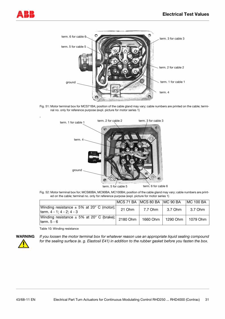
Fig. 51: Motor terminal box for MCS71BA; position of the cable gland may vary; cable numbers are printed on the cable; termi-nal no. only for reference purpose (expl. picture for motor series 1)
.
Fig. 52: Motor terminal box for; MCS80BA, MC90BA, MC100BA; position of the cable gland may vary; cable numbers are print-ed on the cable; terminal no. only for reference purpose (expl. picture for motor series 1)
Table 10: Winding resistance
WARNING If you loosen the motor terminal box for whatever reason use an appropriate liquid sealing compoundfor the sealing surface (e. g. Elastosil E41) in addition to the rubber gasket before you fasten the box.
MCS 71 BA MCS 80 BA MC 90 BA MC 100 BAWinding resistance ± 5% at 20° C (motor);term. 4 - 1; 4 - 2; 4 - 3
21 Ohm 7.7 Ohm 3.7 Ohm 3.7 Ohm
Winding resistance ± 5% at 20° C (brake);term. 5 - 6
2180 Ohm 1660 Ohm 1290 Ohm 1079 Ohm
term. 6 for cable 6
term. 5 for cable 5
term. 3 for cable 3
term. 2 for cable 2
term. 1 for cable 1
term. 4
ground
ground
term. 6 for cable 6term. 5 for cable 5
term. 2 for cable 2 term. 3 for cable 3
term. 4
term. 1 for cable 1
43/68-11 EN Electrical Part Turn Actuators for Continuous Modulating Control RHD250 ... RHD4000 (Contrac) 31
Failure detection
8 Failure detection
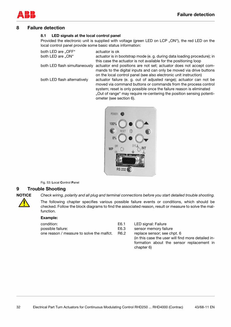
8.1 LED signals at the local control panelProvided the electronic unit is supplied with voltage (green LED on LCP „ON“), the red LED on thelocal control panel provide some basic status information:
both LED are „OFF“ actuator is okboth LED are „ON“ actuator is in bootstrap mode (e. g. during data loading procedure); in
this case the actuator is not available for the positioning loopboth LED flash simultaneously actuator end positions are not set; actuator does not accept com-
mands to the digital inputs and can only be moved via drive buttonson the local control panel (see also electronic unit instruction)
both LED flash alternatively actuator failure (e. g. out of adjusted range); actuator can not bemoved via command buttons or commands from the process controlsystem; reset is only possible once the failure reason is eliminated„Out of range“ may require re-centering the position sensing potenti-ometer (see section 6).
Fig. 53: Local Control Panel
9 Trouble ShootingNOTICE Check wiring, polarity and all plug and terminal connections before you start detailed trouble shooting.
The following chapter specifies various possible failure events or conditions, which should bechecked. Follow the block diagrams to find the associated reason, result or measure to solve the mal-function.
Example:
condition: E6.1 LED signal: Failurepossible failure: E6.3 sensor memory failureone reason / measure to solve the malfct. R6.2 replace sensor; see chpt. 6
(in this case the user will find more detailed in-formation about the sensor replacement inchapter 6)
32 Electrical Part Turn Actuators for Continuous Modulating Control RHD250 ... RHD4000 (Contrac) 43/68-11 EN
Trouble Shooting
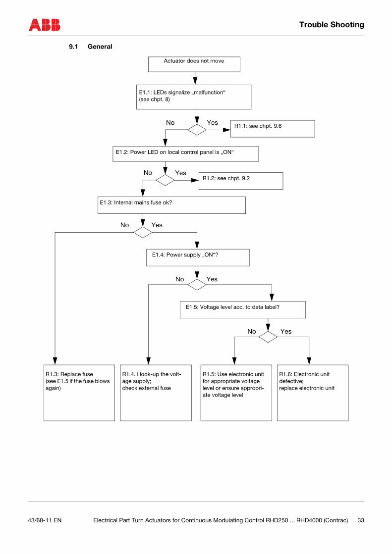
9.1 General
Actuator does not move
E1.1: LEDs signalize „malfunction“(see chpt. 8)
E1.2: Power LED on local control panel is „ON“
No
No Yes
E1.3: Internal mains fuse ok?
E1.4: Power supply „ON“?
E1.5: Voltage level acc. to data label?
R1.3: Replace fuse(see E1.5 if the fuse blows again)
R1.4. Hook-up the volt-age supply;check external fuse
YesNo
YesNo
YesNo
R1.5: Use electronic unit for appropriate voltage level or ensure appropri-ate voltage level
R1.6: Electronic unit defective;replace electronic unit
Yes
R1.1: see chpt. 9.6
R1.2: see chpt. 9.2
43/68-11 EN Electrical Part Turn Actuators for Continuous Modulating Control RHD250 ... RHD4000 (Contrac) 33
Trouble Shooting
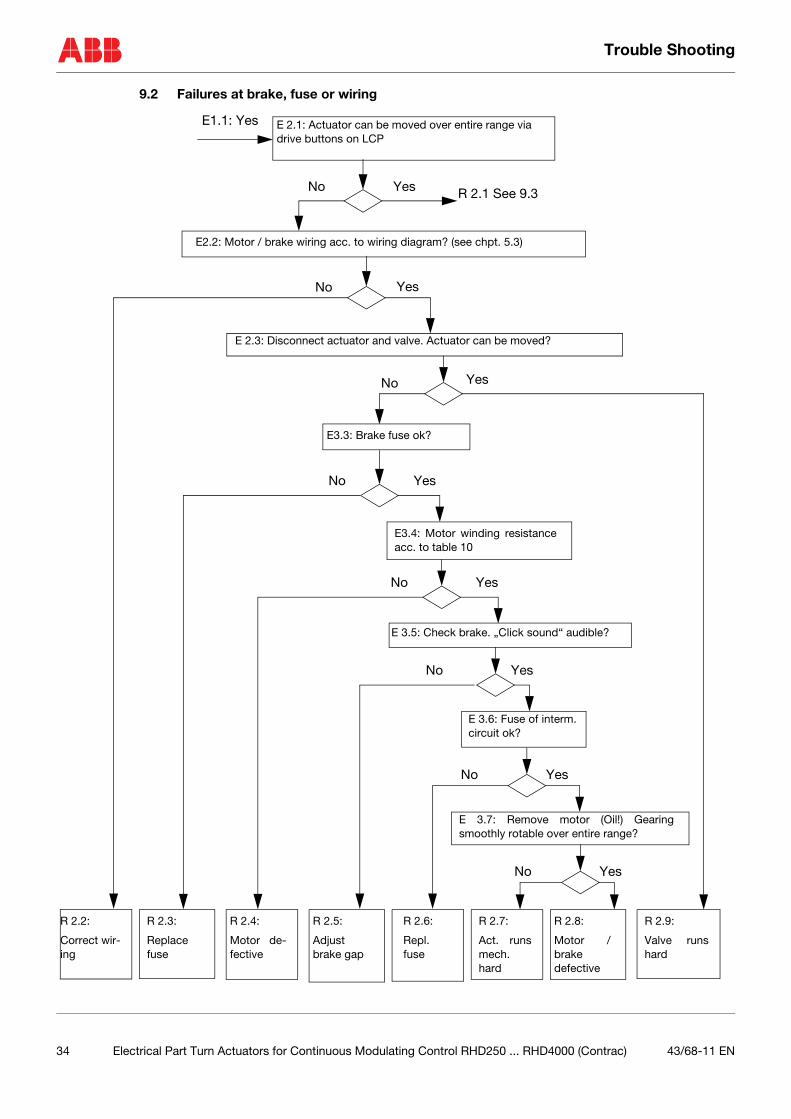
9.2 Failures at brake, fuse or wiring
E 2.1: Actuator can be moved over entire range viadrive buttons on LCP
E2.2: Motor / brake wiring acc. to wiring diagram? (see chpt. 5.3)
No
E1.1: Yes
No Yes
E 2.3: Disconnect actuator and valve. Actuator can be moved?
No Yes
E3.3: Brake fuse ok?
No Yes
E3.4: Motor winding resistanceacc. to table 10
E 3.5: Check brake. „Click sound“ audible?
E 3.6: Fuse of interm.circuit ok?
E 3.7: Remove motor (Oil!) Gearingsmoothly rotable over entire range?
No Yes
No Yes
No Yes
No Yes
Yes
R 2.1 See 9.3
R 2.2:
Correct wir-ing
R 2.3:
Replacefuse
R 2.4:
Motor de-fective
R 2.5:
Adjustbrake gap
R 2.6:
Repl.fuse
R 2.7:
Act. runsmech.hard
R 2.8:
Motor /brake defective
R 2.9:
Valve runshard
34 Electrical Part Turn Actuators for Continuous Modulating Control RHD250 ... RHD4000 (Contrac) 43/68-11 EN
Trouble Shooting
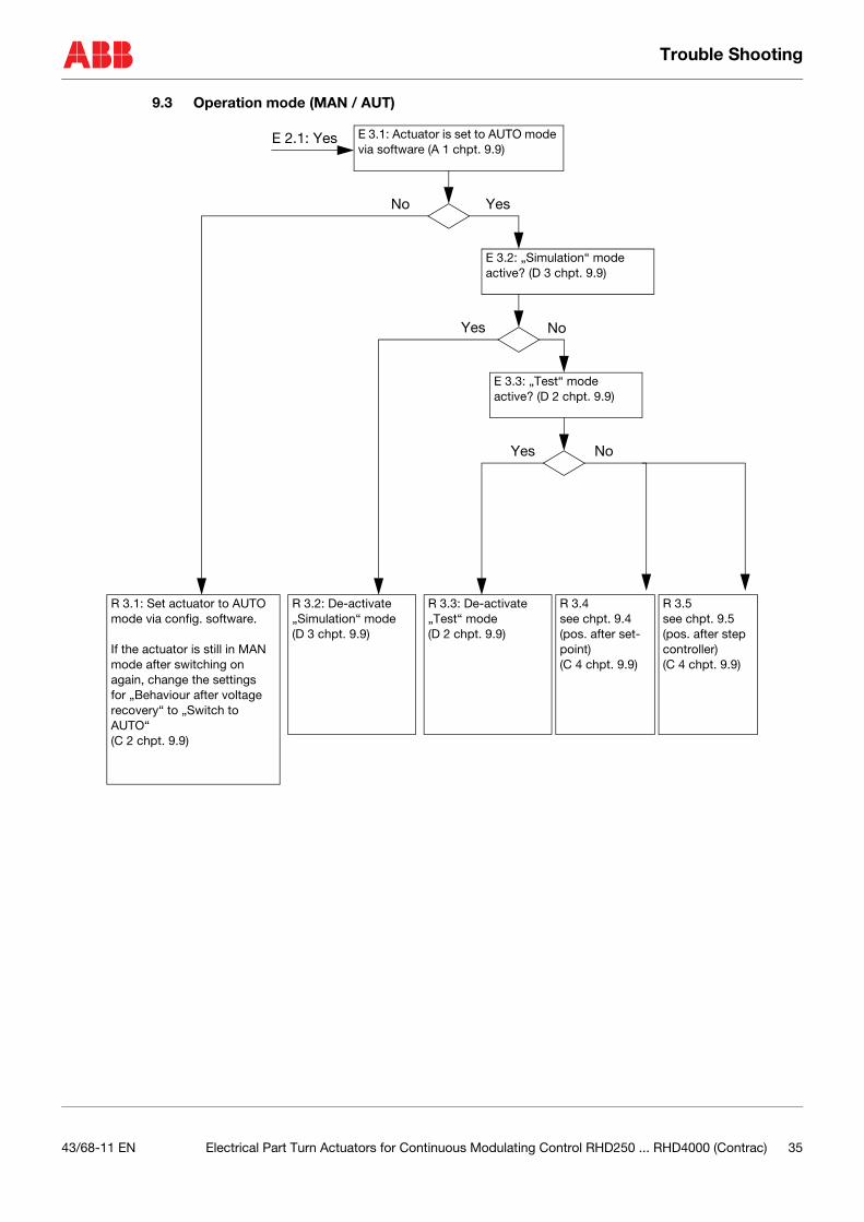
9.3 Operation mode (MAN / AUT)
E 3.1: Actuator is set to AUTO mode via software (A 1 chpt. 9.9)
No Yes
E 2.1: Yes
E 3.2: „Simulation“ mode active? (D 3 chpt. 9.9)
E 3.3: „Test“ mode active? (D 2 chpt. 9.9)
Yes
Yes No
No
R 3.1: Set actuator to AUTO mode via config. software.
If the actuator is still in MAN mode after switching on again, change the settings for „Behaviour after voltage recovery“ to „Switch to AUTO“(C 2 chpt. 9.9)
R 3.2: De-activate „Simulation“ mode (D 3 chpt. 9.9)
R 3.3: De-activate „Test“ mode(D 2 chpt. 9.9)
R 3.4see chpt. 9.4(pos. after set-point)(C 4 chpt. 9.9)
R 3.5 see chpt. 9.5(pos. after step controller)(C 4 chpt. 9.9)
43/68-11 EN Electrical Part Turn Actuators for Continuous Modulating Control RHD250 ... RHD4000 (Contrac) 35
Trouble Shooting
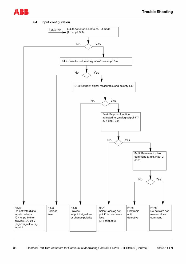
9.4 Input configuration
E 4.1: Actuator is set to AUTO mode(A 1 chpt. 9.9)
E4.2: Fuse for setpoint signal ok? see chpt. 5.4
No
E 3.3: No
E4.3: Setpoint signal measurable and polarity ok?
No Yes
Yes
No Yes
R4.1: De-activate digital input contacts(C 4 chpt. 9.9) orprovide „DC 24 V „high“ signal to dig. input 1
R4.2: Replace fuse
R4.3: Provide setpoint signal and or change polarity
E4.4: Setpoint function adjusted to „analog setpoint“?(C 4 chpt. 9.9)
YesNo
R4.4: Select „analog set-point“ in user inter-face(C 4 chpt. 9.9)
E4.5: Permanent drive command at dig. input 2 or 3?
R4.5: Electronicunitdefective
R4.6: De-activate per-manent drive command
YesNo
36 Electrical Part Turn Actuators for Continuous Modulating Control RHD250 ... RHD4000 (Contrac) 43/68-11 EN
Trouble Shooting
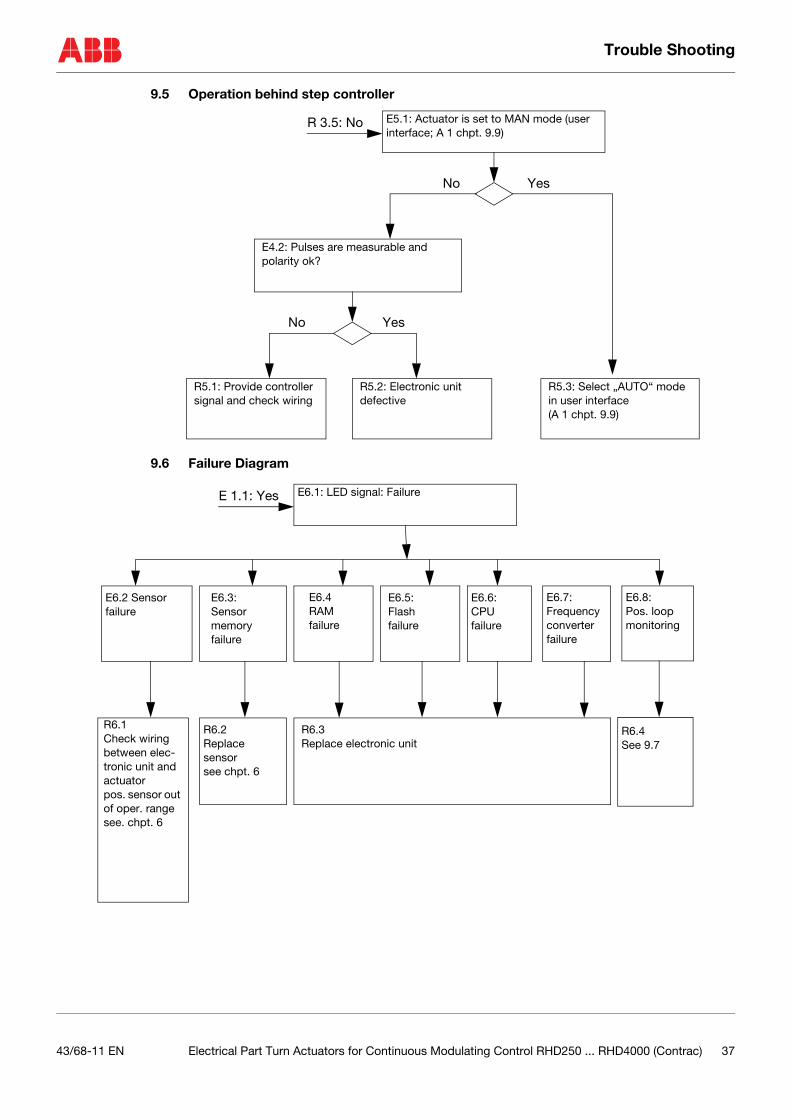
9.5 Operation behind step controller
9.6 Failure Diagram
E5.1: Actuator is set to MAN mode (user interface; A 1 chpt. 9.9)
R 3.5: No
No
R5.3: Select „AUTO“ mode in user interface(A 1 chpt. 9.9)
Yes
E4.2: Pulses are measurable and polarity ok?
Yes
R5.2: Electronic unit defective
R5.1: Provide controller signal and check wiring
No
E6.1: LED signal: FailureE 1.1: Yes
E6.2 Sensor failure
E6.3: Sensor memoryfailure
E6.4RAM failure
E6.5:Flash failure
E6.6:CPU failure
E6.7:Frequency converterfailure
R6.2Replace sensor see chpt. 6
R6.3Replace electronic unit
E6.8:Pos. loopmonitoring
R6.4See 9.7
R6.1Check wiring between elec-tronic unit and actuatorpos. sensor out of oper. rangesee. chpt. 6
43/68-11 EN Electrical Part Turn Actuators for Continuous Modulating Control RHD250 ... RHD4000 (Contrac) 37
Trouble Shooting
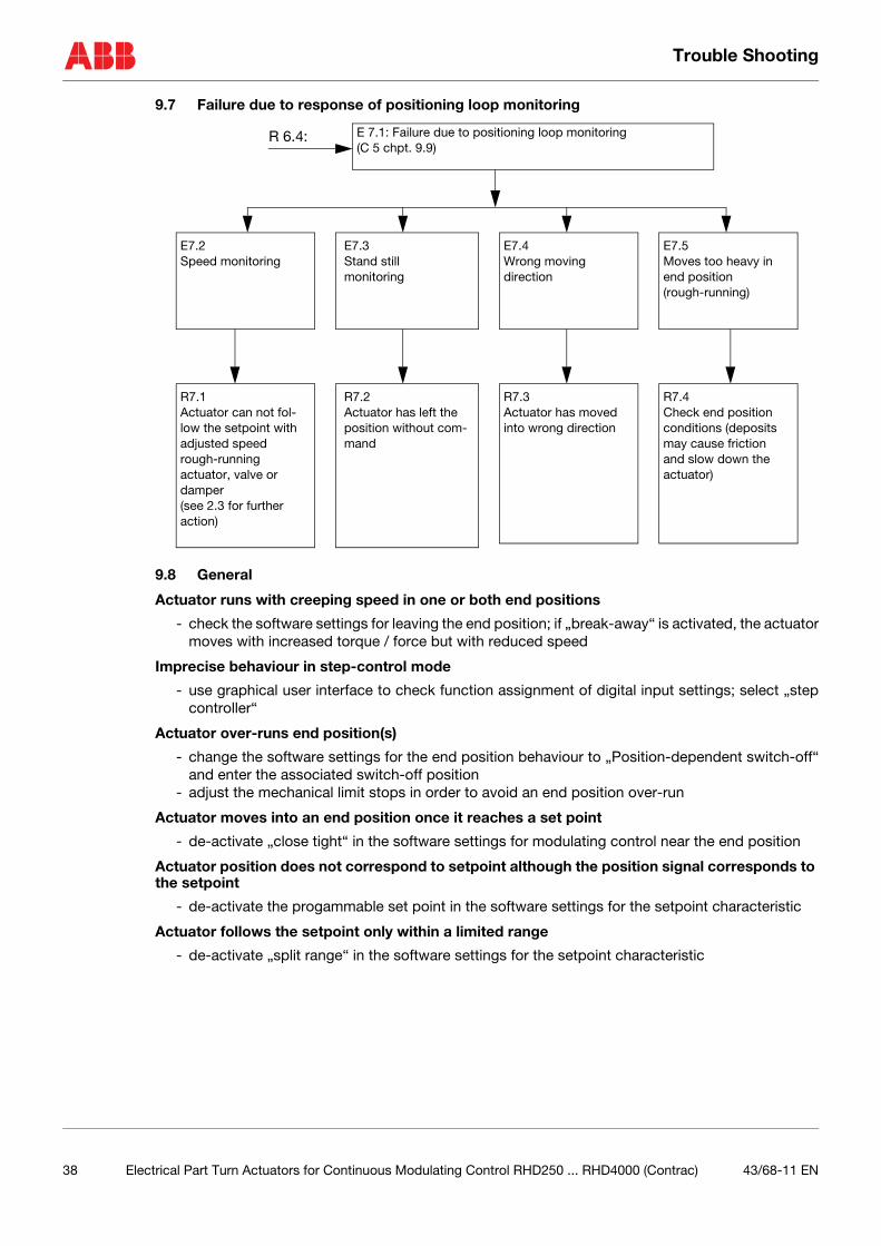
9.7 Failure due to response of positioning loop monitoring
9.8 General
Actuator runs with creeping speed in one or both end positions
- check the software settings for leaving the end position; if „break-away“ is activated, the actuatormoves with increased torque / force but with reduced speed
Imprecise behaviour in step-control mode
- use graphical user interface to check function assignment of digital input settings; select „stepcontroller“
Actuator over-runs end position(s)
- change the software settings for the end position behaviour to „Position-dependent switch-off“and enter the associated switch-off position
- adjust the mechanical limit stops in order to avoid an end position over-run
Actuator moves into an end position once it reaches a set point
- de-activate „close tight“ in the software settings for modulating control near the end position
Actuator position does not correspond to setpoint although the position signal corresponds to the setpoint
- de-activate the progammable set point in the software settings for the setpoint characteristic
Actuator follows the setpoint only within a limited range
- de-activate „split range“ in the software settings for the setpoint characteristic
E 7.1: Failure due to positioning loop monitoring(C 5 chpt. 9.9)
R 6.4:
E7.2Speed monitoring
E7.3Stand still monitoring
E7.4Wrong moving direction
E7.5Moves too heavy in end position(rough-running)
R7.1Actuator can not fol-low the setpoint with adjusted speedrough-running actuator, valve or damper(see 2.3 for further action)
R7.2Actuator has left the position without com-mand
R7.3Actuator has moved into wrong direction
R7.4Check end position conditions (deposits may cause friction and slow down the actuator)
38 Electrical Part Turn Actuators for Continuous Modulating Control RHD250 ... RHD4000 (Contrac) 43/68-11 EN
Trouble Shooting
9.9 User Interface Menus
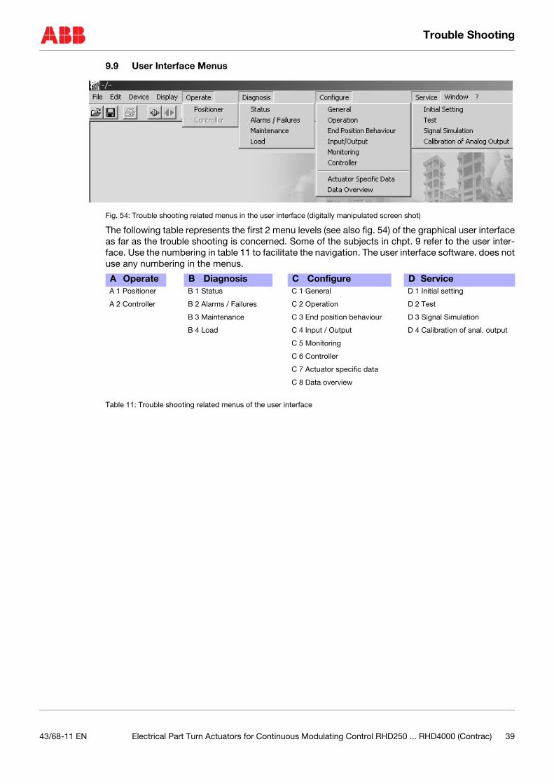
Fig. 54: Trouble shooting related menus in the user interface (digitally manipulated screen shot)
The following table represents the first 2 menu levels (see also fig. 54) of the graphical user interfaceas far as the trouble shooting is concerned. Some of the subjects in chpt. 9 refer to the user inter-face. Use the numbering in table 11 to facilitate the navigation. The user interface software. does notuse any numbering in the menus.
Table 11: Trouble shooting related menus of the user interface
A Operate B Diagnosis C Configure D Service A 1 Positioner B 1 Status C 1 General D 1 Initial setting
A 2 Controller B 2 Alarms / Failures C 2 Operation D 2 Test
B 3 Maintenance C 3 End position behaviour D 3 Signal Simulation
B 4 Load C 4 Input / Output D 4 Calibration of anal. output
C 5 Monitoring
C 6 Controller
C 7 Actuator specific data
C 8 Data overview
43/68-11 EN Electrical Part Turn Actuators for Continuous Modulating Control RHD250 ... RHD4000 (Contrac) 39
43/6
8-11
EN
ABB has Sales & Customer Supportexpertise in over 100 countries worldwide.
www.abb.com/instrumentation
The Company’s policy is one of continuous productimprovement and the right is reserved to modify the
information contained herein without notice.
Printed in the Fed. Rep. of Germany (12.05)
© ABB 2005
ABB Ltd.Salterbeck Trading EstateWorkington, CumbriaCA14 5DSUKTel: +44 (0)1946 830 611Fax: +44 (0)1946 832 661
ABB Inc.125 E. County Line RoadWarminster, PA 18974USATel: +1 215 674 6000Fax: +1 215 674 7183
ABB Automation Products GmbHSchillerstr. 7232425 MindenGermanyTel: +49 551 905-534Fax: +49 551 905-555