Embed Size (px)
Citation preview
SERVICE MANUAL
Dynatron® 125
Dynatron 125
ii
CAUTION: Federal law restricts this device to sale by or on the order of a physician, chiropractor, physical therapist, or dentist licensed by the law of the state in which said person practices to use or order the use of the device.
IMPORTANT: Before treating a patient with the Dynatron 125, read the Contraindications, Warnings, and Precautions in this manual, and observe these whenever treating a patient with this device.
INDICATIONS FOR ULTRASOUND USE: Ultrasound therapy is intended to generate deep heat within body tissues for the treatment of selected medical conditions such as relief of pain, muscle spasms, and joint contractures, but not for the treatment of malignancies.
(21 CFR 890.5300)
Dynatron 125 Service Manual © Copyright 1996 Revised June 2004
Dynatronics Corporation 7030 Park Centre Drive
Salt Lake City, UT 84121 (801) 568-7000 - (800) 874-6251
E-Mail: [email protected] Internet: http://www.dynatronics.com
ALL RIGHTS RESERVED
Rev: 06-04-01
Dynatron 125
Index iii
Table of Contents
Introduction to the Dynatron 125.................................................................................................1 About Ultrasound.......................................................................................................................1
Installation and Features...............................................................................................................2 Unpacking ..................................................................................................................................2 Standard Accessories .................................................................................................................2 Dynatron 125 Physical Features ................................................................................................3 Soundheads ................................................................................................................................5
Treatment Instructions..................................................................................................................6 Soundhead Warming..................................................................................................................6 Turn Soundhead Warming Off / On ..........................................................................................7 Treatment Setup.........................................................................................................................7 Modify a Treatment in Progress ................................................................................................8 Patient Coupling ........................................................................................................................9 Ultrasound Coupling Bar Graph ................................................................................................9 Head Temperature Bar Graph..................................................................................................10 Head Temperature Hot.............................................................................................................11 No Soundhead..........................................................................................................................11 Display Watts or Watts/cm2.....................................................................................................12 Restore Factory Defaults .........................................................................................................12
Battery Operation ........................................................................................................................13 Battery Requirements ..............................................................................................................14 Battery Life ..............................................................................................................................14
Ultrasound With Electrical Stim Input .....................................................................................15
Ultrasound General Information and Usage Cautions ............................................................16 Selecting the Appropriate Soundhead......................................................................................16 Penetration of Ultrasound Waves ............................................................................................17 Types of Delivery ....................................................................................................................18 Treatment Time........................................................................................................................18 Treatment Intensity ..................................................................................................................18 Frequency of Treatment...........................................................................................................19 Continuous Verses Pulsed Ultrasound.....................................................................................19 Duty Cycle ...............................................................................................................................20 Patient Susceptibility ...............................................................................................................20 Potential for Burns or Periosteal Pain......................................................................................20
Dynatron 125
Index iv
Output Power ...........................................................................................................................21 Coupling...................................................................................................................................21 Usage Cautions - Combination Treatments .............................................................................21
Contraindications, Warnings, Precautions ...............................................................................22 Contraindications .....................................................................................................................22 Precautions...............................................................................................................................23 Warnings ..................................................................................................................................23 Usage Cautions - Combination Treatments .............................................................................23 Safety Features of the Dynatron 125 .......................................................................................23
Technical Specifications ..............................................................................................................24 Environmental Conditions .......................................................................................................24 Dynatron 125 Care and Cleaning Instructions.........................................................................25 Suggested Maintenance Schedule............................................................................................25 Routine Calibration Inspections...............................................................................................26 Authorized Service Center.......................................................................................................26 Definition of Symbols..............................................................................................................27 Equipment Classification.........................................................................................................27 Disposal of Equipment and Accessories..................................................................................27
Ultrasound Regulation ................................................................................................................28
Beam Profile .................................................................................................................................30
Enter Soundhead Parameters.....................................................................................................32 New Smart Heads ....................................................................................................................32 Using Older Model Soundheads ..............................................................................................32
Calibration Procedure.................................................................................................................35
Problem Solving ...........................................................................................................................37 Soundhead Temperature Too Hot............................................................................................37 Cooling the Soundhead............................................................................................................37 Whirlpool Treatments ..............................................................................................................37 Soundhead Temperature Too Cold ..........................................................................................38 Error Message in the Display...................................................................................................38
Sending a Unit in for Repair .......................................................................................................39 Return Authorization ...............................................................................................................39 Why the Information is Necessary...........................................................................................39 Packaging and Shipping of Replacement Parts .......................................................................40
Dynatron 125
Index v
Installing Software Updates ........................................................................................................41
Installing Replacement Parts......................................................................................................41
Medical Device Reporting Requirements ..................................................................................41
Schematics and QC Check Lists.................................................................................................42

Dynatron 125
vi
Dynatron 125
Introduction 1
Introduction to the Dynatron 125 Your new Dynatron 125 gives you a wide range of treatment capabilities, yet it is compact, convenient and simple to use. You’ll appreciate the user-friendly touch panel for easy treatment setup. With the Dynatron 125 you can select two different frequencies without changing the soundhead. The 2 cm2, 5 cm2, and 10 cm2 soundheads each operate at 1 and 3 MHz. The desired frequency is easily selected during treatment setup.
Here are some additional highlights of your Dynatron 125:
• Customizable Duty Cycle. Select from 10, 20, 50 percent, and Continuous duty cycle options.
• Head Warming. When the device is ON but idle, the soundhead is warmed automatically. Head warming may be turned OFF, if it is not desired.
• Coupling Sensing. If coupling becomes inadequate during a treatment, the displays flash and an audible beep is sounded to notify the user that coupling should be corrected. If your device is version 1.04 or above, a bar graph will appear.
• Modify Treatments in Progress. You can modify treatment time, power, frequency, or duty cycle, while a treatment is in progress. It is not necessary to stop the treatment.
• Portable. The Dynatron 125’s small, light-weight size makes it readily portable. An optional carry case is available from your Dynatronics dealer.
• Optional Battery Operation. The device may be operated with power supplied by an optional battery, offering greater flexibility in treatment sites.
This manual provides instructions for Ultrasound setup and treatment with the Dynatron 125. Please read this manual, particularly the section on contraindications, warnings and precautions, before treating a patient with this device.
About Ultrasound Ultrasound therapy is supported by a wealth of scientific literature. Channeling sound waves through muscle, nerve, bone and connective tissue has been documented to aid in reducing pain, muscle spasms, and joint contractures. The “Ultrasound Usage Cautions” in this manual provide some general guidelines for Ultrasound treatment to help ensure you deliver safe and effective treatments to your patients. Further information about Ultrasound may be obtained from published medical literature.
Before using your Dynatron 125, be sure to read the operating instructions, contraindications, warnings, and precautions contained in this manual.
Dynatron 125
2
Installation and Features Unpacking
When you receive the unit, immediately unpack it and all accessories and check for possible damage, obvious or concealed. In case of damage, immediately notify the carrier and take any steps necessary to file a claim for the damage sustained. Do not destroy or discard the shipping carton. The carton should be reused if the device must be shipped for any reason. The carton is specially designed to protect the unit from shipping damage. Improper packaging of the unit during transport can result in damage and invalidate the warranty. Complete the warranty registration form found at the back of this manual and return it to Dynatronics within 30 days of purchase. This is essential to insure you are not billed for services that are covered by the warranty policy. Connect the AC power cord, which is equipped with a hospital grade, UL listed plug, to a properly grounded 110/120V 60 Hz AC outlet. The device will automatically switch to 220/240V 50 Hz when connected to a power source with that voltage. Do not place the cord or the device in a place where the cord could be tripped over or accidentally pulled out of its socket during a treatment. Read the operating instructions and the contraindications, warnings and precautions in this manual before proceeding with a treatment.
Standard Accessories Qty Description
1 Dynatron 125 unit 1 Power cord 1 Operator’s manual 1 Applicator soundhead Optional Accessories Additional soundheads are available in sizes 2 cm2, 5 cm2, or 10 cm2. Rechargeable battery pack Pin-to-banana adapter for Stim input Ultrasound coupling gel
Dynatron 125
Installation & Features 3
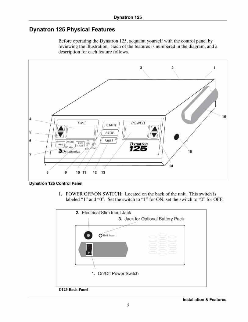
Dynatron 125 Physical Features Before operating the Dynatron 125, acquaint yourself with the control panel by reviewing the illustration. Each of the features is numbered in the diagram, and a description for each feature follows.
1
Dynatronics
FREQ
4
5
9
15
3
1 MHz
3 MHz
DUTYCYCLE
POWERTIME
PAUSE
STOP
START
10%
50%
20%
CONT
1210 11
7
6
8 13
14
16
2
Dynatron 125 Control Panel
1. POWER OFF/ON SWITCH: Located on the back of the unit. This switch is
labeled “1” and “0”. Set the switch to “1” for ON; set the switch to “0” for OFF.
1
0
Batt. Input
2. Electrical Stim Input Jack
1. On/Off Power Switch
3. Jack for Optional Battery Pack
D125 Back Panel
Dynatron 125
Installation & Features 4
2. ELECTRICAL STIM INPUT JACK: This jack is used for combining Ultrasound with electrical stimulation. The output end of a lead connected to a Dynatron electrotherapy device may be plugged into this jack. The current from the Stim device is delivered through the soundhead.
3. BATTERY INPUT: This input located on the back of the device provides
connection to an optional battery power source. Only a Dynatronics-approved battery may be used.
4. TIME DISPLAY: Treatment time is displayed in this window. 5. TIME SELECTION: UP/DOWN ARROW keys are used to set or change the
treatment time. Press the UP ARROW key to increase time, and press the DOWN ARROW key to decrease the treatment time.
6. FREQUENCY KEY: This key is pressed to select the desired frequency during
treatment setup or while a treatment is in progress. Select from 1 or 3 MHz. Continue pressing the FREQUENCY key until the desired frequency is selected.
7. FREQUENCY DISPLAY: LED lights indicate the frequency that is chosen for
the current treatment. Selection is made by pressing the FREQUENCY key. 8. DUTY CYCLE KEY: This key is pressed to select the desired duty cycle during
treatment setup or while a treatment is in progress. Select from 10, 20, 50 percent or Continuous duty cycle. Continue pressing the DUTY CYCLE key until the desired duty cycle is selected.
9. DUTY CYCLE DISPLAY: LED lights indicate the duty cycle that is chosen for
the current treatment. Selection is made by pressing the DUTY CYCLE key.
10. START: When this key is pressed the selected treatment starts. The timer begins counting down and output from the soundhead is started.
11. STOP: Pressing this key stops the output to the applicator head, resets the timer
to zero, and ends the treatment. 12. PAUSE: This key is pressed to pause an Ultrasound treatment in progress. When
the treatment is paused, the treatment timer is stopped, an LED on the PAUSE key is lighted and the output power is stopped. Pressing the START key or the PAUSE key will resume the treatment; the timer resumes counting down, power is delivered to the soundhead, and the PAUSE LED light will be off.
13. POWER DISPLAY: This display shows the power selected for the current
treatment. Power is displayed in watts per square centimeter (WATT/cm2). WATT/cm2 is the intensity of the Ultrasound at the head surface; it is the total watts divided by the effective radiating area of the head. The display may be changed to WATTS, if desired, by pressing both the UP and DOWN power keys at the same time; the decimal in the display will flash continuously when displaying WATTS. The decimal remains solid when displaying WATT/cm2.
Dynatron 125
Installation & Features 5
14. POWER SELECTION KEYS: These UP/DOWN ARROW keys are used to set or change the power setting for a treatment. Press the UP ARROW key to increase power, and press the DOWN ARROW key to decrease power.
15. ULTRASOUND OUTPUT JACK: The soundhead plugs into this jack for
Ultrasound therapy. 16. SOUNDHEAD HOLDER: The soundhead is placed in this holder when not in
use. Soundheads
Soundheads for the Dynatron 125 are available in 2 cm2, 5 cm2, and 10 cm2 sizes. Each soundhead operates at 1, and 3 MHz. The soundheads are waterproof allowing therapy to be administered in water, if desired. Information regarding calibration of soundheads is provided later in this manual.
Dynatron 125
Treatment Instructions 6
Treatment Instructions CAUTION: Use of controls, adjustments or performance of procedures other than those specified herein may result in hazardous exposure to ultrasonic energy.
WARNING
• ALWAYS keep the applicator soundhead in constant motion.
• ALWAYS keep the soundhead properly coupled to the patient’s skin or submerged under water when intensity is turned ON.
• Read and observe the contraindications, warnings, and precautions provided in this manual.
• Be sure to read all instructions given in this manual before treating a patient.
Make sure a soundhead is firmly plugged into the device before turning ON the device. When changing to a different size soundhead, turn the machine OFF first, remove the soundhead, plug in the desired soundhead, then turn the machine ON again. Press the power switch on the back of the device to turn on the Dynatron 125. It is recommended that the unit remain ON throughout the day if it is used regularly. If the device is being powered by the optional battery, unplug the battery or turn the battery OFF after treatment has ended to save battery power. When the unit is first powered ON, it goes through an automatic self-test and head check procedure. After the calibration procedure is completed, the device is available for treatment. To set up a treatment, press keys on the keypad to select time, duty cycle, frequency, and power. Treatment settings may be modified at any time during a treatment. Before treating a patient with the Dynatron 125, you should be familiar with all the features of the device in order to deliver treatments easily, effectively, and safely.
Soundhead Warming
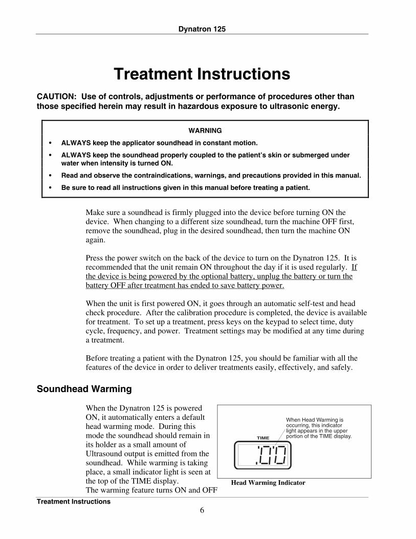
When the Dynatron 125 is powered ON, it automatically enters a default head warming mode. During this mode the soundhead should remain in its holder as a small amount of Ultrasound output is emitted from the soundhead. While warming is taking place, a small indicator light is seen at the top of the TIME display. The warming feature turns ON and OFF
TIME
When Head Warming is occurring, this indicator light appears in the upper portion of the TIME display.
Head Warming Indicator
Dynatron 125
Treatment Instructions 7
automatically as needed to maintain a comfortable temperature. The soundhead warming mode is automatically stopped during a treatment, and resumes automatically as needed after a treatment has ended.
Turn Soundhead Warming Off / On
If you do not wish to use the head warming feature, you can turn the feature OFF with a simple key press: • Press both the PAUSE and the STOP keys simultaneously to turn soundhead
warming OFF or to turn it ON again. These key presses are only necessary if you want to change the current state of head warming.
The head warming setting you select whether OFF or ON is saved and will apply to the device whenever it is used until you change the setting again.
Treatment Setup
CAUTION: Set intensity to MINIMUM POWER before pressing START.
The following is the sequence for setting up a treatment. 1. Set Time: Press the UP/DOWN ARROW keys to set the time for the treatment. When treatment starts, a countdown timer displays the time remaining in the
treatment. 2. Set Duty Cycle: Press the DUTY CYCLE TOGGLE key one or more times to
select the desired duty cycle: Continuous, 50, 20, or 10 percent. Your selection is indicated by a green light next to the selected option.
3. Choose Frequency: Press the FREQ key to select the frequency (1 or 3 MHz).
Your selection is indicated by a green light next to the selected option. 4. Set Power: Using the UP/DOWN ARROW keys, enter the power in watts per
square centimeter (W/cm2). Valid ranges for each soundhead size are found in the Technical Specifications
section of this manual. For patient safety and comfort, it is recommended that you start with 0.1 W/cm2
then increase power to the desired level after the treatment begins. 5. Coupling Agent: Be sure to use a coupling agent such as a gel or lotion designed
for Ultrasound usage, and maintain good coupling throughout the treatment (see Ultrasound Usage Cautions in this manual). Do not hold the soundhead in the air,
Dynatron 125
Treatment Instructions 8
as this will cause the soundhead to overheat. The device provides coupling sensing to help you know when coupling is not adequate. This feature is discussed later in this manual.
6. Press START: When you press START, power is delivered to the soundhead
and the treatment timer begins counting down. When the timer reaches zero, output power is stopped.
7. Treat: Administer the treatment using your preferred Ultrasound protocol.
Modify any treatment parameters during the treatment, if desired. Maintain good coupling throughout the treatment.
8. Stop Treatment: At any time during the treatment you can stop the treatment by
pressing STOP on the keypad. When STOP is pressed during a treatment, the timer goes to zero, the output power is stopped, and a chime sounds. If you press PAUSE during the treatment, the output stops and the timer stops counting down, but the treatment may be resumed by pressing PAUSE again or START.
IMPORTANT For patient safety and comfort, it is recommended that you start with 0.1 W/cm2, and then increase power to the desired level after the treatment begins.
Modify a Treatment in Progress The following parameters may be modified during a treatment: • Frequency. Press the FREQUENCY TOGGLE key • Duty Cycle. Press the DUTY CYCLE TOGGLE key. • Time. Press the UP/DOWN ARROWS to increase or decrease time. • Power. Press the UP/DOWN arrows to increase or decrease power. • Display Power in WATTS or WATTS/cm2. Press both the UP and DOWN
POWER DISPLAY keys simultaneously to change the display. When displaying power in WATTS, the decimal in the POWER DISPLAY will flash. When displaying power in WATTS/cm2, the decimal remains solid.
Pressing the PAUSE key will temporarily stop a treatment in progress; this stops both the timer and the output. To resume the treatment, press the START or PAUSE key. Pressing the STOP key terminates the treatment. The output is stopped and the treatment timer is set to zero.
Dynatron 125
Treatment Instructions 9
Patient Coupling The Dynatron 125 provides the feature of PATIENT COUPLING SENSING which senses the coupling between the soundhead and the patient to ensure proper delivery of the Ultrasonic therapy (this feature is in effect during CONTINUOUS duty cycle only and works best at 1.0 W/cm2 or greater). Coupling (contact between the soundhead and the treatment site) may be provided either via a coupling agent such as a gel or lotion, or in water, as with underwater treatments. Any material used as a coupling agent must be highly conductive of ultrasonic waves. Air is a very poor conductor of ultrasonic waves. Therefore, avoid allowing any air between the soundhead and the treatment area. During the treatment the soundhead should be moved continuously covering an area approximately twice the size of the soundhead in area. The full surface of the soundhead should maintain contact with the patient’s skin (except with underwater treatments). If all or part of the soundhead is not touching the patient, coupling may not be adequate and the patient will not receive the intended dosage of the ultrasonic wave and/or the soundhead may warm up very quickly.
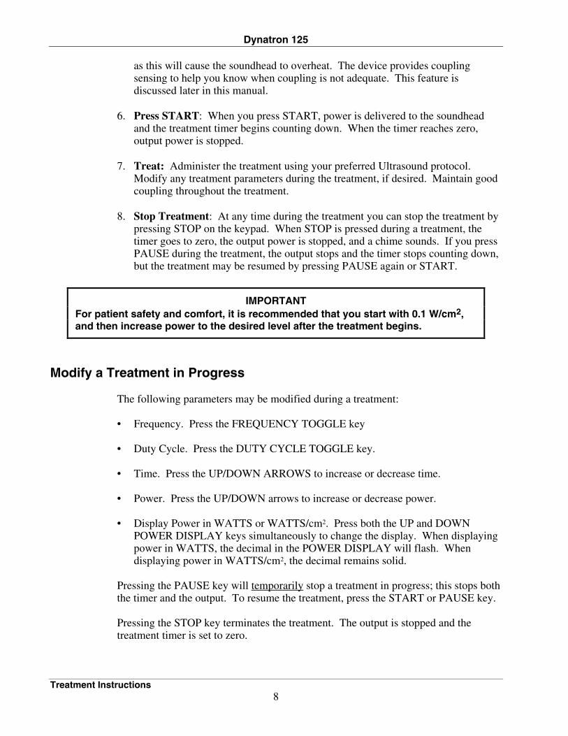
Ultrasound Coupling Bar Graph APPLIES ONLY TO VERSIONS 1.04 AND ABOVE During an Ultrasound treatment, you can display a bar graph to indicate coupling; that is, whether adequate contact is being maintained between the soundhead and the patient’s skin. The bar graph uses the eight segments in the top half of the TIME DISPLAY, with eight lighted segments indicating best conductance, and one lighted segment indicating poorest conductance. In the illustration below, eight of the eight segments are lighted indicating best coupling.
POWERTIMESTART
STOP
PAUSE
Ultrasound Coupling Bar Graph
Press the START and the Time UP arrow keys simultaneously during an ultrasound treatment to view a graph showingsoundhead coupling. Press the START key to return to thetreatment time display.
Coupling Bar Graph: Eight lighted segments indicate good coupling between patient and soundhead.
Dynatron 125
Treatment Instructions 10
To correct poor coupling make sure you are using an adequate amount of Ultrasound conductive gel and the face of the soundhead is making full contact with the patient’s skin. To turn-on the ULTRASOUND COUPLING BAR GRAPH function, press PAUSE and the POWER DOWN ARROW keys simultaneously. Repeat the action to toggle between ON and OFF. Visible in the TIME DISPLAY window: CP1 indicates the bar graph is ON, while CP0 indicates the bar graph is OFF. To display the BAR GRAPH, displayed on the previous page, press the START key and the TIME UP ARROW key simultaneously. The treatment time continues counting down while the bar graph is displayed unless the treatment is paused for any reason. You may alternate (toggle back and forth) between the BAR GRAPH and the treatment TIME by pressing the PAUSE and POWER DOWN ARROW keys simultaneously. When you no longer require the bar graph display, press the START key to turn OFF the BAR GRAPH and redisplay the treatment TIME. Pressing the TIME UP or DOWN ARROW key will also change the display from bar graph to the treatment time display; however, pressing these keys will change the treatment time as well. Changes to the treatment settings including frequency, duty cycle, and size of soundhead will cause some variance in the graph.
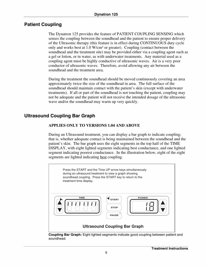
Head Temperature Bar Graph During an Ultrasound treatment, you can view a graph showing the relative soundhead temperature by pressing START and the TIME DOWN ARROW keys simultaneously. As shown in the illustration below, the TIME DISPLAY shows the letter “H” followed by a bar graph with from 1 to 6 segments lighted. The more segments displayed, the hotter the soundhead. This display does not provide an actual temperature reading, but does give a visual indication if the soundhead is becoming too hot. To return to the treatment time display, press the START key.
POWERTIMESTART
STOP
PAUSE
Head Temperature Bar Graph
Press the START and the Time DOWN arrow keys simultaneously during an ultrasound treatment to view a graph showingrelative head temperature. Press the START key to return to thetreatment time display.
Temperature Bar Graph: During an Ultrasound treatment, press START and the TIME Down Arrow keys simultaneously to view a bar graph representing the soundhead temperature.
Dynatron 125
Treatment Instructions 11
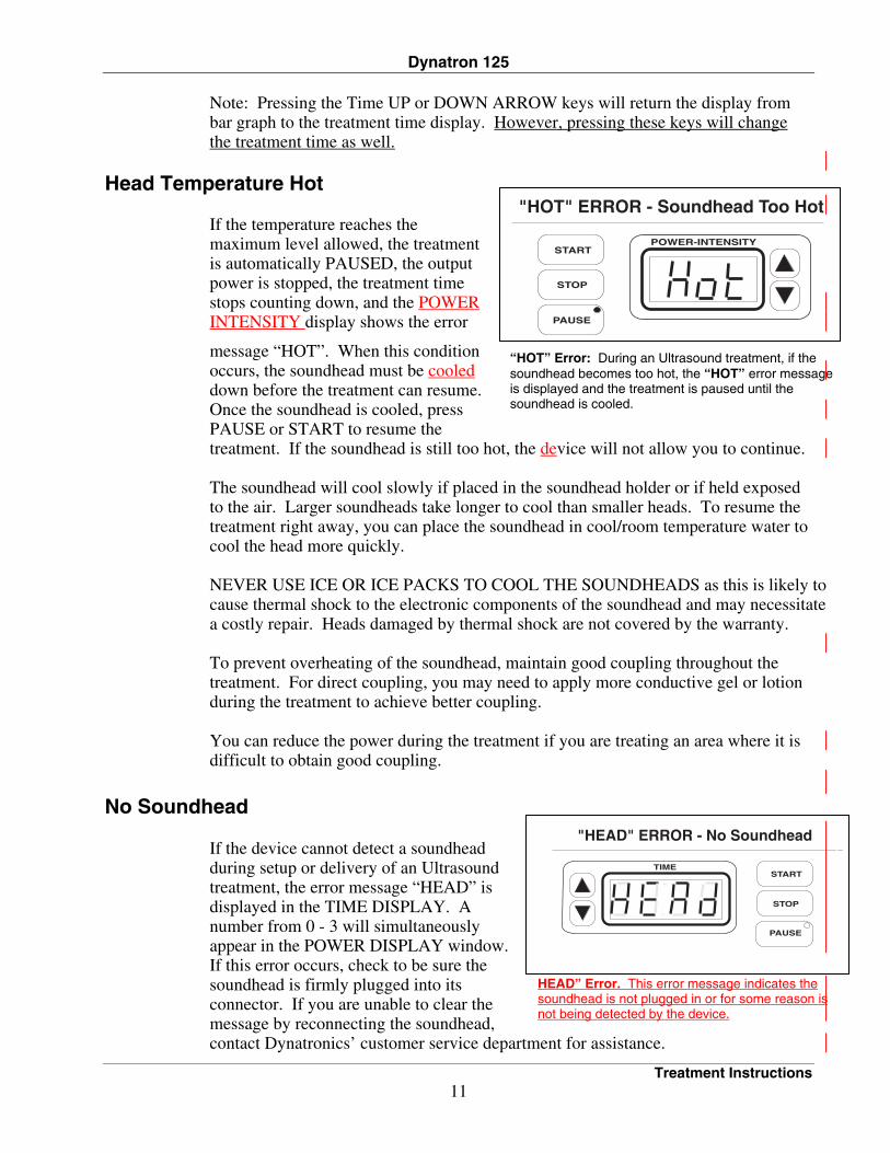
“HOT” Error: During an Ultrasound treatment, if the soundhead becomes too hot, the “HOT” error message is displayed and the treatment is paused until the soundhead is cooled.
POWER-INTENSITYSTART
STOP
PAUSE
"HOT" ERROR - Soundhead Too Hot
Note: Pressing the Time UP or DOWN ARROW keys will return the display from bar graph to the treatment time display. However, pressing these keys will change the treatment time as well.
Head Temperature Hot
If the temperature reaches the maximum level allowed, the treatment is automatically PAUSED, the output power is stopped, the treatment time stops counting down, and the POWER INTENSITY display shows the error
message “HOT”. When this condition occurs, the soundhead must be cooled down before the treatment can resume. Once the soundhead is cooled, press PAUSE or START to resume the treatment. If the soundhead is still too hot, the device will not allow you to continue. The soundhead will cool slowly if placed in the soundhead holder or if held exposed to the air. Larger soundheads take longer to cool than smaller heads. To resume the treatment right away, you can place the soundhead in cool/room temperature water to cool the head more quickly. NEVER USE ICE OR ICE PACKS TO COOL THE SOUNDHEADS as this is likely to cause thermal shock to the electronic components of the soundhead and may necessitate a costly repair. Heads damaged by thermal shock are not covered by the warranty. To prevent overheating of the soundhead, maintain good coupling throughout the treatment. For direct coupling, you may need to apply more conductive gel or lotion during the treatment to achieve better coupling. You can reduce the power during the treatment if you are treating an area where it is difficult to obtain good coupling.
No Soundhead
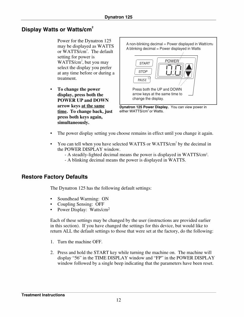
If the device cannot detect a soundhead during setup or delivery of an Ultrasound treatment, the error message “HEAD” is displayed in the TIME DISPLAY. A number from 0 - 3 will simultaneously appear in the POWER DISPLAY window. If this error occurs, check to be sure the soundhead is firmly plugged into its connector. If you are unable to clear the message by reconnecting the soundhead, contact Dynatronics’ customer service department for assistance.
HEAD” Error. This error message indicates the soundhead is not plugged in or for some reason is not being detected by the device.
TIMESTART
STOP
PAUSE
"HEAD" ERROR - No Soundhead
Dynatron 125
Treatment Instructions 12
Display Watts or Watts/cm2
Power for the Dynatron 125 may be displayed as WATTS or WATTS/cm2. The default setting for power is WATTS/cm2, but you may select the display you prefer at any time before or during a treatment.
• To change the power
display, press both the POWER UP and DOWN arrow keys at the same time. To change back, just press both keys again, simultaneously.
• The power display setting you choose remains in effect until you change it again. • You can tell when you have selected WATTS or WATTS/cm2 by the decimal in
the POWER DISPLAY window. - A steadily-lighted decimal means the power is displayed in WATTS/cm2. - A blinking decimal means the power is displayed in WATTS.
Restore Factory Defaults The Dynatron 125 has the following default settings: • Soundhead Warming: ON • Coupling Sensing: OFF • Power Display: Watts/cm2 Each of these settings may be changed by the user (instructions are provided earlier in this section). If you have changed the settings for this device, but would like to return ALL the default settings to those that were set at the factory, do the following: 1. Turn the machine OFF. 2. Press and hold the START key while turning the machine on. The machine will
display “56” in the TIME DISPLAY window and “FP” in the POWER DISPLAY window followed by a single beep indicating that the parameters have been reset.
Dynatron 125 Power Display. You can view power in either WATTS/cm2
or Watts.
Press both the UP and DOWN arrow keys at the same time to change the display.
POWER
PAUSE
STOP
START
A non-blinking decimal = Power displayed in Watt/cm2
A blinking decimal = Power displayed in Watts
Dynatron 125
Battery Operation 13
Battery Operation
Use ONLY a Dynatronics-Approved Battery
Contact Dynatronics or your Dynatronics dealer to purchase the optional battery or to obtain specifications for an acceptable battery that may be used. Do not substitute another battery without first confirming with Dynatronics that the battery you are purchasing may be used with this device. Only use a battery that CANNOT be recharged while it is in use. Disconnect the battery charger from the AC power source before using the battery to supply power to this device.
An optional battery is available for the Dynatron 125, allowing you to deliver battery-powered treatments wherever power may be unavailable or unreliable. To use the optional battery, do the following: 1. Before use, ensure the battery has been adequately charged. DISCONNECT the
battery charging cable from the battery while it is in use for treatment. 2. Plug the battery adapter into the jack labeled BATT on the back of the Dynatron
125 device. Turn the battery pack ON. 3. Set up and deliver treatments as you normally do. 4. When available battery power is reduced to a certain level, the device will flash a
message BATT LO to indicate low battery power. The treatment can continue but you will probably be unable to set up and deliver another treatment when the current treatment has ended.
5. When the available battery power becomes too low to continue operating the
device, the BATT LO message is again displayed, the treatment intensity is ramped down, and the machine is then shut OFF. Before you can continue with battery operation of the device, you must recharge the battery. If battery power is fully depleted, the message BATT BAD is displayed to indicate either a bad battery or to indicate the battery must be recharged. Any treatments that were running at that time will stop.
NOTE: Use the ON/OFF switch on the battery pack to control power to the device during battery operation. While the battery is attached, the battery’s ON/OFF switch controls power to the device.
Dynatron 125
Battery Operation 14
Battery Requirements • 12 volt and at least 5 amps peak current (1.5 ampere hours minimum). Do not substitute the Dynatron battery without first confirming with Dynatronics
that the battery you are purchasing may be used with this device. • Battery Adapter Cord
- Cigarette lighter plug on one end (to attach to the battery pack) and a barrel plug on the other end (to fit a .325 barrel jack).
- The cord must be a high quality gauge wire. (Radio Shack carries a high
quality cord that is recommended. Cat. No. 270-1534D. This cord comes with a 2 amp fuse which must be replaced with a 5 amp fast blow fuse.)
Note: If a low-quality gauge cord is used, you can get the BATT LO error when the battery is not low.
Battery Life The length of time that a unit can be used with a battery pack is dependent on several factors: • The amperage of the battery pack. A larger amperage will provide longer use. • The modality used. Ultrasound requires more power than stim modalities. • The intensity of the treatments. The higher the intensity, the higher the
consumption of power. • The amount of charge remaining on the battery. As a general rule, the unit may be run continuously for 30 minutes to several hours depending on these factors.
Dynatron 125
Ultrasound With Electrical Stim Input 15
Ultrasound With Electrical Stim Input NOTE: The stimulator device to be connected to this unit shall comply with IEC 601-1 and IEC 601-2-10 (general and particular standards) requirements.
The Dynatron 125 allows you to combine electrical stim therapy with Ultrasound therapy. The device accepts input from electrotherapy devices through the Stim Input jack found on the back of the device. This jack accommodates a banana adapter (a pin-to-banana adapter is attached to one output end of a patient lead). The following instructions explain how to use the Dynatron 125 with Dynatronics’ electrotherapy devices. With this type of treatment, the soundhead acts as one of the electrodes in a 2-electrode stim treatment, and stim is delivered through the soundhead. See “Usage Cautions - Combination Treatments” in this manual before using this option. 1. Plug a patient lead into one channel of the Dynatron electrotherapy device. Use a
single lead with two output connectors. Place a pin-to-banana adapter on one output end of the lead, then plug that banana
adapter into Stim Input jack on the back of the Dynatron 125. NOTE: If you do not have a pin-to banana adapter, contact Dynatronics to order.
Attach the other lead output to an electrode (use an electrode that you normally
use with your Dynatron electrotherapy device) and place the electrode in the desired location on the patient’s body. The electrode should be placed slightly outside the area where the Ultrasound will be delivered to allow full movement of the soundhead over the treatment area. Remember the soundhead delivers Stim as well as Ultrasound during the treatment, and therefore, the soundhead acts as the second electrode. Consider this when you determine where to place the electrode and the soundhead on the patient.
2. Set up an Ultrasound treatment with the Dynatron 125. Do not press START. 3. Set up the Stim treatment for the appropriate channel on the Dynatron
electrotherapy device. Use a very low stim intensity for this type of treatment. 4. START the treatments at both devices. During the treatment, the Stim current is delivered through the soundhead and will pass between the soundhead and the electrode which was placed on the patient. At the same time ultrasonic waves are introduced into patient tissue through the soundhead. Avoid touching the electrode with the soundhead during the treatment, and keep the Stim intensity low.
Dynatron 125
Ultrasound Usage Cautions 16
Ultrasound General Information and Usage Cautions
Ultrasound, by its very nature, has the ability to irritate the patient’s skin. While the benefits of Ultrasound far outweigh any disadvantages, certain precautions should be observed to assure maximum safety and comfort for your patients.
A patient’s tendency to have adverse reactions to Ultrasound is dependent upon several factors. Some of these factors are discussed below. In addition to cautions listed below, read the contraindications, warnings, and other precautions in this manual.
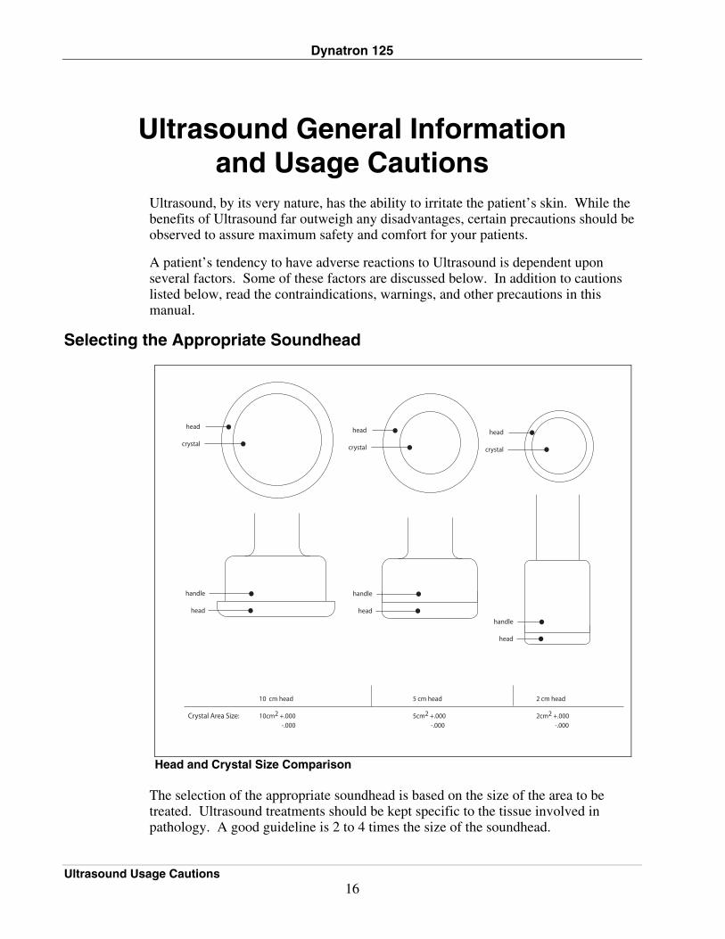
Selecting the Appropriate Soundhead
Head and Crystal Size Comparison The selection of the appropriate soundhead is based on the size of the area to be treated. Ultrasound treatments should be kept specific to the tissue involved in pathology. A good guideline is 2 to 4 times the size of the soundhead.
Dynatron 125
Ultrasound Usage Cautions 17
Multi-Frequency Ultrasound
For example: • A 2 cm2 soundhead can deliver up to 4 Watts and is appropriate for small areas
(i.e. hands, fingers, feet). • A 5 cm2 soundhead can deliver up to 10 Watts and is appropriate for medium
sized areas (i.e. extremities such as arms, legs and cervical areas). • A 10 cm2 soundhead can deliver up to 20 Watts and is appropriate for large areas (i.e. torso and back).
Ultrasound is a directed beam of energy. Therefore, not only will the average spatial intensity be a factor in the dosage the patient receives, but the time delivered and area covered will matter as well. For example, an area of 50 cm2 is treated for 5 minutes. Then an area of 200 cm2 is treated for 5 minutes. Both receive the same intensity. The 200 cm2 area however does not receive the same dosage (only ¼) because as the soundhead is moved around the area it has to cover represents 4 times as much tissue.
The Soundhead area measurement is the ERA (effective radiating area). Each soundhead has an effective radiating area. It is not necessarily the outside diameter of the soundhead, but the area of the crystal inside, therefore special care should be taken in selecting the correct size soundhead for the area to be treated according to the diameter of the crystal. See the Head and Crystal Size Comparison graphic on the previous page.
NOTE: If a patient experiences pain during a treatment, the size of the soundhead may be inappropriate for the area being treated, the intensity is too high or the treatment time is too long.
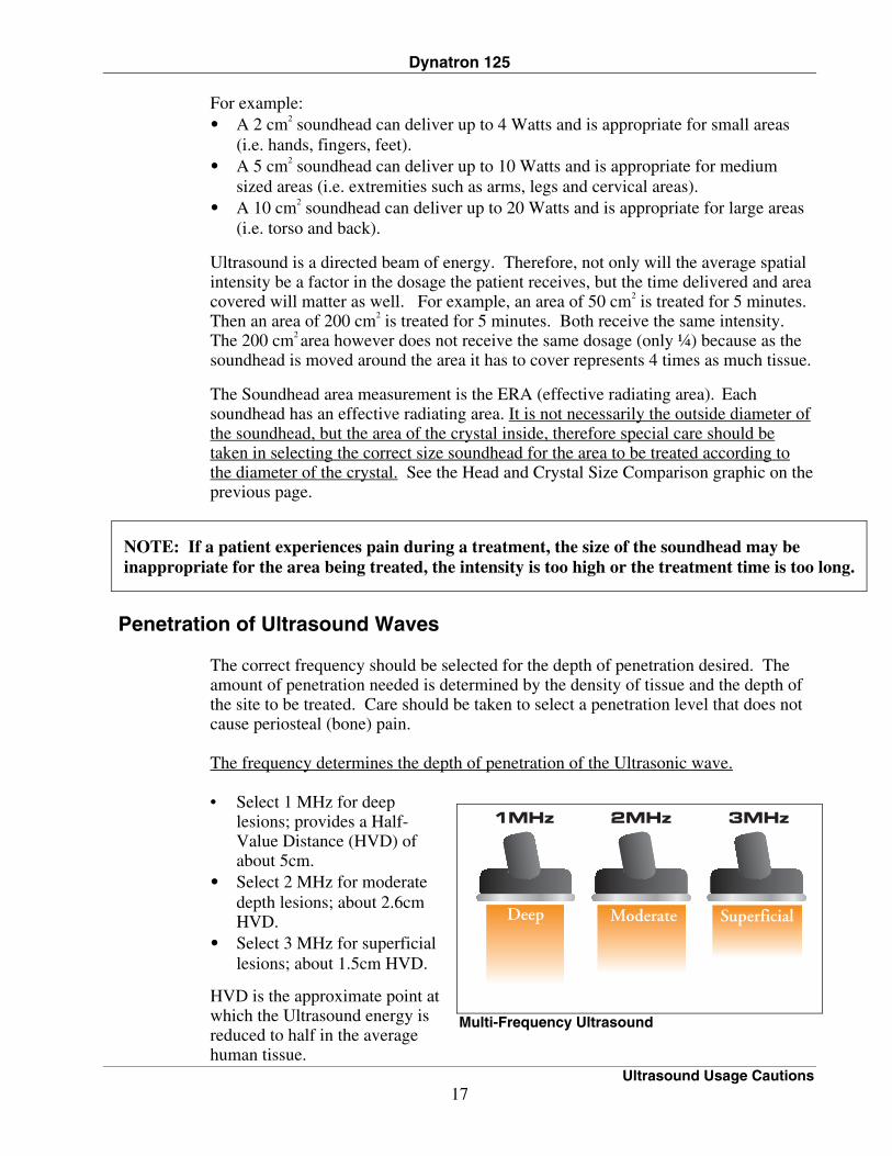
Penetration of Ultrasound Waves
The correct frequency should be selected for the depth of penetration desired. The amount of penetration needed is determined by the density of tissue and the depth of the site to be treated. Care should be taken to select a penetration level that does not cause periosteal (bone) pain. The frequency determines the depth of penetration of the Ultrasonic wave. • Select 1 MHz for deep
lesions; provides a Half-Value Distance (HVD) of about 5cm.
• Select 2 MHz for moderate depth lesions; about 2.6cm HVD.
• Select 3 MHz for superficial lesions; about 1.5cm HVD.
HVD is the approximate point at which the Ultrasound energy is reduced to half in the average human tissue.
Dynatron 125
Ultrasound Usage Cautions 18
Types of Delivery Ultrasound can be delivered in four different ways. You will likely only see two of the four methods in clinical practice. 1. Direct Contact Movable: Here the soundhead is placed in direct contact with the
patient, a coupling agent is used between soundhead and the patient’s skin. The soundhead is moved slowly, but continuously. This is the method of choice.
The rate of speed at which the applicator moves across the skin is very important in determining how much Ultrasonic output is delivered. If the rate is too slow, the patient may feel periosteal pain (bone ache/pain). It the rate is too fast, or if the applicator head becomes uncoupled with the skin, the amount of treatment is reduced. Uncoupling can also cause the soundhead to overheat.
2. Immersion Method: Here the area to be treated is placed underwater. The
soundhead is water tight so it can be immersed with the area to be treated. The water becomes the coupling agent. The head is always moving around the surface area, but not in contact (1/2 to 1 inch away).
3. Hydrogel Disk: For treating crater wounds, cover the wound with a hydrogel disk
and apply the soundhead to the disk. This allows direct wound sonation without bringing the soundhead in direct contact with the wound.
4. Stationary Soundhead: This method is dangerous. Hot spots can develop. Do not
use.
Treatment Time For Sub-Acute Conditions: area to be treated (cm2) = minutes of treatment 1.5 x ERA For Chronic Conditions: area to be treated (cm2) = minutes of treatment
1.0 x ERA For Maximal Thermal Effect: area to be treated (cm2) = minutes of treatment 0.8 x ERA
Treatment Intensity Several factors come into play as one decides the level of intensity for the treatment. 1. Superficial lesions require less intensity. 2. Less intensity should be used if bone is superficial to the treatment field. 3. Less intensity should be used when the stage of the injury makes heating
questionable. 4. Use a little lower intensity for the first treatment to gauge response.
Dynatron 125
Ultrasound Usage Cautions 19
5. Patient feedback is key. A treatment should feel warm, but the patient should never feel heat, pain, stabbing, pricking or dull ache.
Acute Conditions: 0.1 – 0.5 W/cm2 (no appreciable thermal effect). Sub-Acute Conditions: 0.5 – 1.0 W/cm2 (Mild to Moderate thermal effect). Chronic Conditions: 1.0 – 2.0 W/cm2 (Moderate to Strong thermal effect). NOTE: It is very common that intensity is always 1.5 W/cm2. This is incorrect in many cases. A more specific intensity should be used based on patient response and stage of injury.
Frequency of Treatment
Treatment can be given daily. It is not uncommon to give Ultrasound twice daily, but this may be excessive. Some guidelines may be helpful: 1. Daily may be the best maximum frequency. 2. Ultrasound can be effectively given every other day. 3. Ultrasound should give some positive benefits by the 3rd or 4th application. If not,
discontinue the treatment and consider other options. 4. A maximum of 12 to 15 Ultrasound treatments should be given. If the result
desired has not been reached by this point, Ultrasound may not be the proper choice..
EXCEPTION: Some Chronic conditions which cause adhesions.
Continuous Verses Pulsed Ultrasound
Ultrasound can be delivered in one of two modes. Continuous means that the ultrasound energy is delivered uninterrupted form the time the intensity is raised until it is lowered again to zero. Pulsed means that some of the time during every second, the sound energy is interrupted. The peak intensity might be set the same for two treatments, one given continuously and the other given in a pulsed mode. 1. Less total energy will be given in the pulsed mode. 2. Pulsed sound is often used when less thermal effect is desired.
NOTE: The same result could be accomplished by lowering the intensity in continuous mode.
3. Pulsed sound may have applications for wound management.
Dynatron 125
Ultrasound Usage Cautions 20
Duty Cycle Duty Cycle is when the Ultrasound energy is subjected to regular and predictable interruption (pulsed) or no interruption (continuous). The Dynatron 125 can be set at 10%, 20%, 50% or continuous. • Continuous is 100% • 50% Duty Cycle means that during every second of treatment, there is as much
OFF time as ON time (usually microsecond pulses). • 20% means there is four times as much OFF time as ON time. Every second has
20% of the time when energy is flowing and 80% when it is not. • 10% means that for every second, 10% of the time energy is flowing and 90% of
the time, it is not.
Patient Susceptibility
Some patients’ skin is more sensitive to Ultrasound output. This can cause a reaction similar to a heat rash.
Potential for Burns or Periosteal Pain It is possible for a patient to suffer a burn from Ultrasound therapy if the therapy is not administered properly. This can occur for the following reasons: • Intensity (power) too high • Frequency too low • Holding the soundhead in one place on the patient’s skin • Moving the soundhead too slowly • Treating an area where sensory nerve damage is present with a loss of normal
skin sensation • Time (Caution: Don’t treat too long). Bony prominences are especially susceptible, as they reflect sound waves and increase intensity to the periosteum resulting in a burning sensation. Desensitized areas can be overheated or burned without the patient realizing it, so extreme care must be taken with these patients (e.g. diabetes, neural damage, etc.)
Burns can be avoided as long as the treatment causes no pain, tingling, excess heat or aching (for patients with normal skin sensation). Use sufficient coupling agent and make sure there are no bubbles in the gel. When treating in water, clear the bubbles off the soundhead and off the patient’s skin. An uncalibrated unit can also cause tingling, excess heat, aching, or a burning sensation.
Dynatron 125
Ultrasound Usage Cautions 21
Output Power Higher output levels have a greater potential for patient discomfort. Output power may be reduced by simply choosing a lower watt setting. Output power is also effectively reduced by selecting a pulsed duty cycle.
Coupling The term “coupling” refers to the ability to deliver ultrasonic waves from the soundhead to the skin surface with as little impedance or dissipation of power as possible. The best coupling is achieved when the soundhead has full, direct contact over the treatment site or when the treatment site and soundhead are separated only by a substance that provides excellent conductance. For example, water is an excellent conductor of ultrasonic waves. Therefore, Ultrasound treatment in water provides excellent coupling. Air is a poor conductor of ultrasonic waves. If any part of the soundhead is exposed to air during the treatment, coupling is decreased. The air bubbles in a whirlpool, for example, can decrease the effective Ultrasound therapy to the patient. When treating a patient outside of water, the soundhead must maintain good contact with the patient’s skin at all times. In addition, a good conductive gel or lotion should be used to ensure the best possible coupling. Many such products are commercially available specifically for Ultrasound therapy.
Usage Cautions - Combination Treatments When using a Stim device in conjunction with the Dynatron 125 to output Stim through the soundhead, observe all contraindications, warnings, precautions, and usage cautions provided by the manufacturer for that Stim therapy along with all contraindications, warnings, precautions, and usage cautions for Ultrasound therapy provided in this manual.
Dynatron 125
Contraindications, Warnings, Precautions 22
Contraindications, Warnings, Precautions Contraindications
The Dynatron 125 Ultrasound should not be applied in the following conditions: • Pregnancy • Acute and sub-acute thrombosis and thrombophlebitis • Potentially malignant lesions, tumors malignant or benign • Areas or lumps that may be suspected as cancerous or precancerous • Third degree musculo-tendonous lesions • Cardiac pacemaker • Implants of any electrical nature • Skin diseases • Multiple sclerosis • Osteomyelitis • Disturbances in cardiac rhythm • Tissue or bone with acute sepsis • Arteriosclerosis or weakened blood vessels • Hemophilia • Where sensory nerve damage is present with a loss of normal skin sensation. The Dynatron 125 Ultrasound should not be applied to the following areas: • Transcerebrally • To the eye • To the ear • Over a carotid sinus • To the heart • To major subcutaneous nerves and blood vessels • To the spinal cord • Around the bulbar area of the spinal cord • To reproductive organs • Over viscera (stomach, spleen, liver) • Over epiphyseal areas of the bones in growing children • Over stellate ganglion and subcutaneous major nerves • To tissues previously treated by deep x-ray or other radiation • Over the joint capsule in acute or sub-acute arthritic conditions • Over ischemic tissue in patients with vascular disease • Over a laminectomy site • Over total joint replacements (the effect of Ultrasound on the new plastics is
unknown) • Over healing fractures
Dynatron 125
Contraindication, Warnings, Precautions 23
POWER SHOULD BE REDUCED IF PATIENT COMPLAINS OF PERIOSTEAL BONE PAIN (BONE ACHE)
Precautions
The Dynatron 125 must be used cautiously in the presence of any of the following conditions: • When there is a tendency to hemorrhage following acute trauma or fracture. • Acute Bursitis: Do not use in continuous duty cycle mode.
Warnings • Do not use in general area where high-powered, high-frequency transmitting units
are being operated. Short wave diathermy should not be turned on or used at the same time as the Dynatron 125.
• Do not use the same power outlet or line with a whirlpool and certain traction machines.
• In areas which are carpeted and static electricity is present, it may be necessary to use a conductive mat to remove any static charge from the operator.
• Use a surge suppresser if power problems are encountered. • Avoid unnecessary exposure to Ultrasound (patient and therapist) NOTE: For further technical information on therapeutic Ultrasound and its physiological effects, please consult published medical literature.
Usage Cautions - Combination Treatments When using a Stim device in conjunction with the Dynatron 125 to output Stim through the soundhead, observe all contraindications, warnings, precautions, and usage cautions provided by the manufacturer for that Stim therapy along with all contraindications, warnings, precautions, and usage cautions for Ultrasound therapy provided in this manual.
Safety Features of the Dynatron 125 • The device senses coupling and soundhead temperature to help ensure proper
delivery of the ultrasonic therapy and to protect the soundhead crystal. • The device provides complete isolation of patient connection from AC power
line.
Dynatron 125
Technical Specifications 24
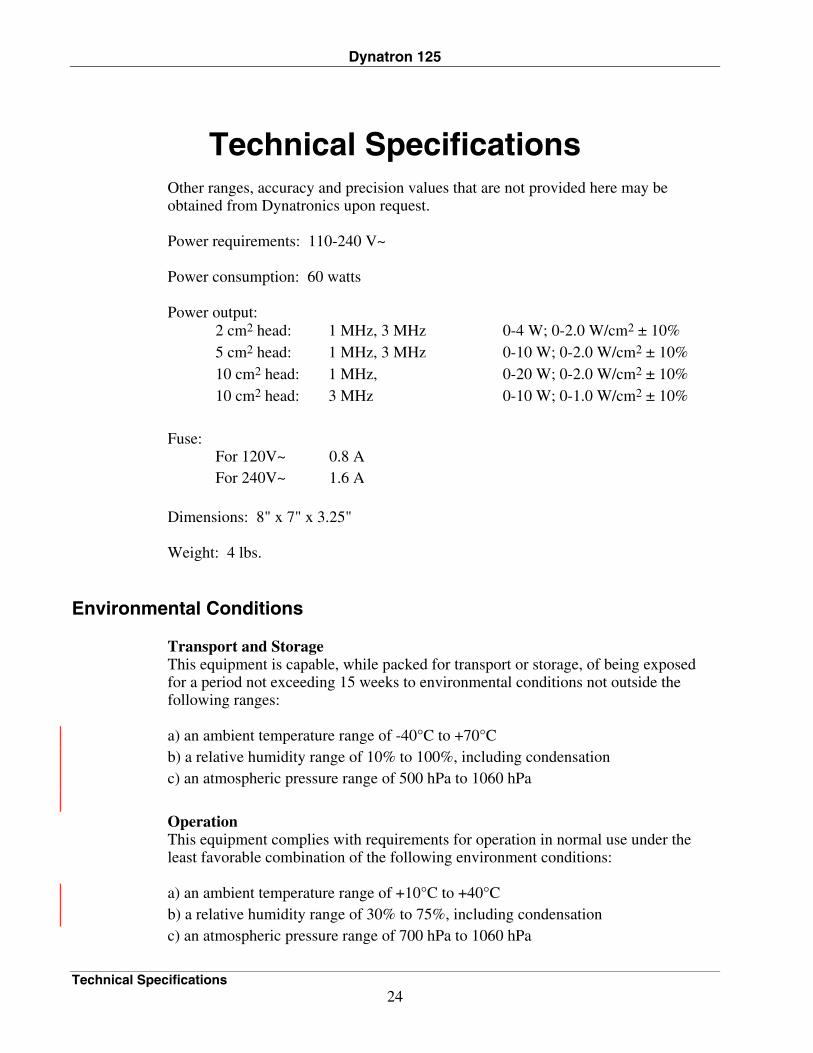
Technical Specifications Other ranges, accuracy and precision values that are not provided here may be obtained from Dynatronics upon request. Power requirements: 110-240 V~ Power consumption: 60 watts Power output: 2 cm2 head: 1 MHz, 3 MHz 0-4 W; 0-2.0 W/cm2 ± 10% 5 cm2 head: 1 MHz, 3 MHz 0-10 W; 0-2.0 W/cm2 ± 10% 10 cm2 head: 1 MHz, 0-20 W; 0-2.0 W/cm2 ± 10% 10 cm2 head: 3 MHz 0-10 W; 0-1.0 W/cm2 ± 10% Fuse: For 120V~ 0.8 A For 240V~ 1.6 A Dimensions: 8" x 7" x 3.25" Weight: 4 lbs.
Environmental Conditions Transport and Storage This equipment is capable, while packed for transport or storage, of being exposed for a period not exceeding 15 weeks to environmental conditions not outside the following ranges: a) an ambient temperature range of -40°C to +70°C b) a relative humidity range of 10% to 100%, including condensation c) an atmospheric pressure range of 500 hPa to 1060 hPa Operation This equipment complies with requirements for operation in normal use under the least favorable combination of the following environment conditions: a) an ambient temperature range of +10°C to +40°C b) a relative humidity range of 30% to 75%, including condensation c) an atmospheric pressure range of 700 hPa to 1060 hPa
Dynatron 125
Technical Specifications 25
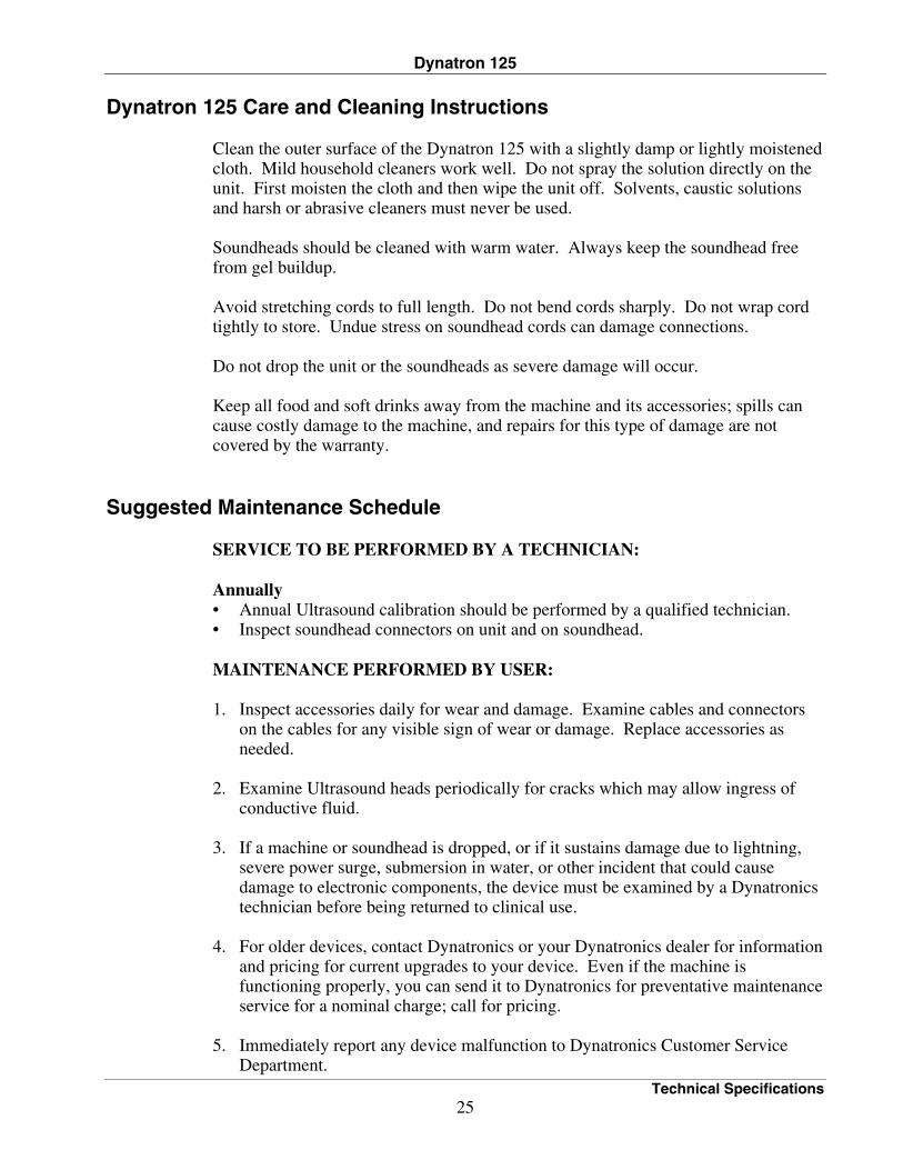
Dynatron 125 Care and Cleaning Instructions Clean the outer surface of the Dynatron 125 with a slightly damp or lightly moistened cloth. Mild household cleaners work well. Do not spray the solution directly on the unit. First moisten the cloth and then wipe the unit off. Solvents, caustic solutions and harsh or abrasive cleaners must never be used. Soundheads should be cleaned with warm water. Always keep the soundhead free from gel buildup. Avoid stretching cords to full length. Do not bend cords sharply. Do not wrap cord tightly to store. Undue stress on soundhead cords can damage connections. Do not drop the unit or the soundheads as severe damage will occur. Keep all food and soft drinks away from the machine and its accessories; spills can cause costly damage to the machine, and repairs for this type of damage are not covered by the warranty.
Suggested Maintenance Schedule SERVICE TO BE PERFORMED BY A TECHNICIAN: Annually • Annual Ultrasound calibration should be performed by a qualified technician. • Inspect soundhead connectors on unit and on soundhead. MAINTENANCE PERFORMED BY USER: 1. Inspect accessories daily for wear and damage. Examine cables and connectors
on the cables for any visible sign of wear or damage. Replace accessories as needed.
2. Examine Ultrasound heads periodically for cracks which may allow ingress of
conductive fluid. 3. If a machine or soundhead is dropped, or if it sustains damage due to lightning,
severe power surge, submersion in water, or other incident that could cause damage to electronic components, the device must be examined by a Dynatronics technician before being returned to clinical use.
4. For older devices, contact Dynatronics or your Dynatronics dealer for information
and pricing for current upgrades to your device. Even if the machine is functioning properly, you can send it to Dynatronics for preventative maintenance service for a nominal charge; call for pricing.
5. Immediately report any device malfunction to Dynatronics Customer Service
Department.
Dynatron 125
Technical Specifications 26
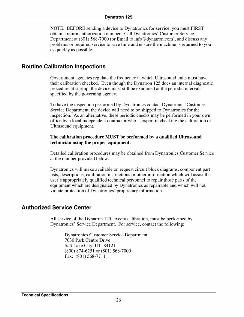
NOTE: BEFORE sending a device to Dynatronics for service, you must FIRST obtain a return authorization number. Call Dynatronics’ Customer Service Department at (801) 568-7000 (or Email to [email protected]), and discuss any problems or required service to save time and ensure the machine is returned to you as quickly as possible.
Routine Calibration Inspections Government agencies regulate the frequency at which Ultrasound units must have their calibration checked. Even though the Dynatron 125 does an internal diagnostic procedure at startup, the device must still be examined at the periodic intervals specified by the governing agency. To have the inspection performed by Dynatronics contact Dynatronics Customer Service Department, the device will need to be shipped to Dynatronics for the inspection. As an alternative, these periodic checks may be performed in your own office by a local independent contractor who is expert in checking the calibration of Ultrasound equipment. The calibration procedure MUST be performed by a qualified Ultrasound technician using the proper equipment. Detailed calibration procedures may be obtained from Dynatronics Customer Service at the number provided below. Dynatronics will make available on request circuit block diagrams, component part lists, descriptions, calibration instructions or other information which will assist the user’s appropriately qualified technical personnel to repair those parts of the equipment which are designated by Dynatronics as repairable and which will not violate protection of Dynatronics’ proprietary information.
Authorized Service Center All service of the Dynatron 125, except calibration, must be performed by Dynatronics’ Service Department. For service, contact the following:
Dynatronics Customer Service Department 7030 Park Centre Drive Salt Lake City, UT 84121 (800) 874-6251 or (801) 568-7000 Fax: (801) 568-7711
Dynatron 125
Technical Specifications 27
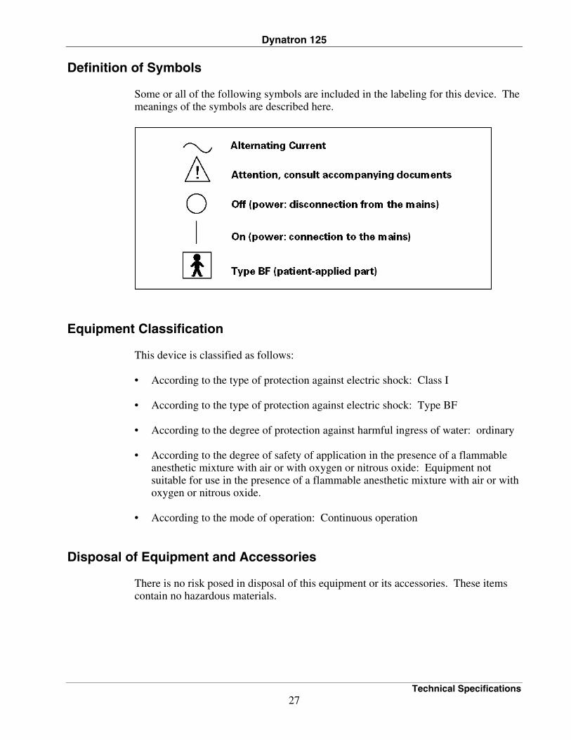
Definition of Symbols Some or all of the following symbols are included in the labeling for this device. The meanings of the symbols are described here.
Equipment Classification
This device is classified as follows: • According to the type of protection against electric shock: Class I • According to the type of protection against electric shock: Type BF • According to the degree of protection against harmful ingress of water: ordinary • According to the degree of safety of application in the presence of a flammable
anesthetic mixture with air or with oxygen or nitrous oxide: Equipment not suitable for use in the presence of a flammable anesthetic mixture with air or with oxygen or nitrous oxide.
• According to the mode of operation: Continuous operation
Disposal of Equipment and Accessories There is no risk posed in disposal of this equipment or its accessories. These items contain no hazardous materials.
Dynatron 125
Ultrasound Regulation 28
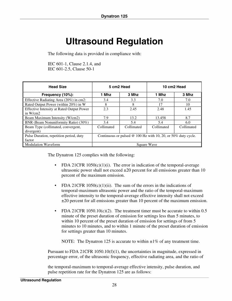
Ultrasound Regulation The following data is provided in compliance with:
IEC 601-1, Clause 2.1.4, and IEC 601-2.5, Clause 50-1
Head Size 5 cm2 Head 10 cm2 Head
Frequency (10%): 1 Mhz 3 Mhz 1 Mhz 3 Mhz Effective Radiating Area (20%) in cm2: 3.4 3.3 7.0 7.0 Rated Output Power (within 20%) in W 8 8 17 10 Effective Intensity at Rated Output Power
in W/cm2 2.3 2.45 2.48 1.45
Beam Maximum Intensity (W/cm2) 7.9 13.2 13.458 8.7 BNR (Beam Nonuniformity Ratio) (30%) 3.4 5.4 5.4 6.0 Beam Type (collimated, convergent,
divergent) Collimated Collimated Collimated Collimated
Pulse Duration, repetition period, duty factor
Continuous or pulsed @ 100 Hz with 10, 20, or 50% duty cycle.
Modulation Waveform Square Wave
The Dynatron 125 complies with the following:
• FDA 21CFR 1050(c)(1)(i). The error in indication of the temporal-average ultrasonic power shall not exceed ±20 percent for all emissions greater than 10 percent of the maximum emission.
• FDA 21CFR 1050(c)(1)(ii). The sum of the errors in the indications of
temporal-maximum ultrasonic power and the ratio of the temporal-maximum effective intensity to the temporal-average effective intensity shall not exceed ±20 percent for all emissions greater than 10 percent of the maximum emission.
• FDA 21CFR 1050.10(c)(2). The treatment timer must be accurate to within 0.5
minute of the preset duration of emission for settings less than 5 minutes, to within 10 percent of the preset duration of emission for settings of from 5 minutes to 10 minutes, and to within 1 minute of the preset duration of emission for settings greater than 10 minutes.
NOTE: The Dynatron 125 is accurate to within ±1% of any treatment time.
Pursuant to FDA 21CFR 1050.10(f)(1), the uncertainties in magnitude, expressed in percentage error, of the ultrasonic frequency, effective radiating area, and the ratio of the temporal-maximum to temporal-average effective intensity, pulse duration, and pulse repetition rate for the Dynatron 125 are as follows:
Dynatron 125
Ultrasound Regulation 29
(1) Ultrasonic frequency ...............................±15% (2) Effective Radiating Area .........................±50% (3) Ratio of the temporal-maximum to temporal-average effective intensity .......±20% (4) Pulse duration ..........................................±10% (5) Pulse repetition rate .................................±10%
Dynatron 125
Beam Profile 30
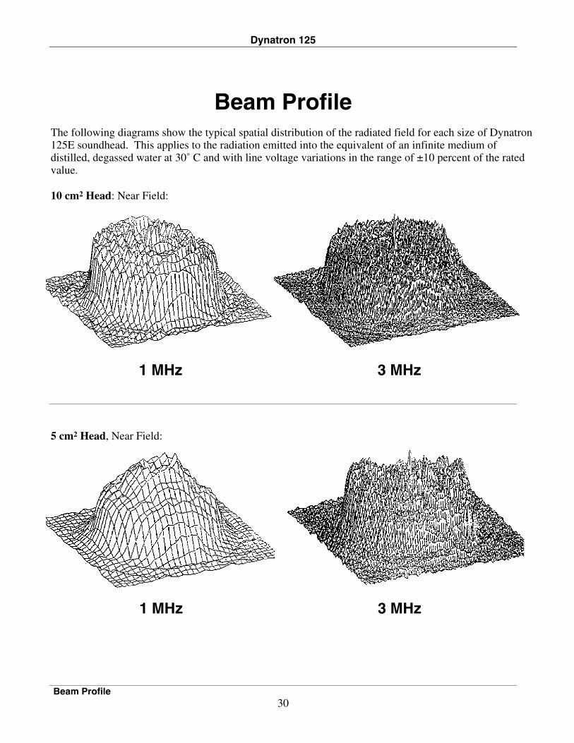
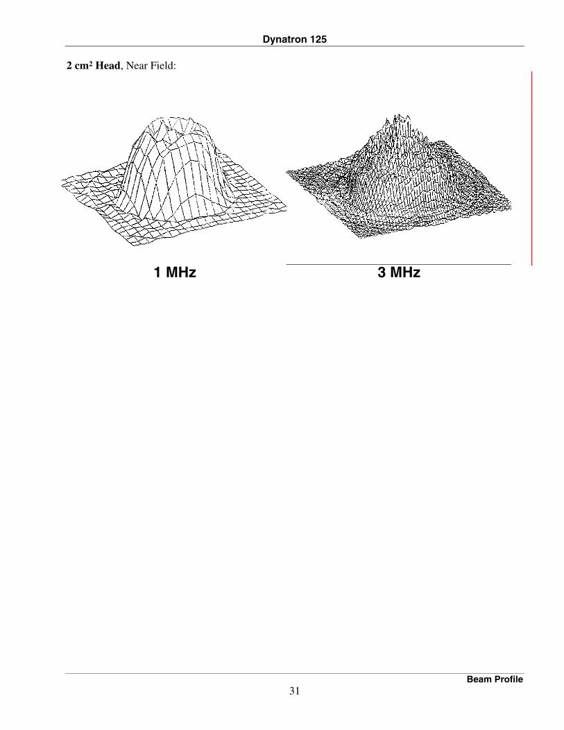
Beam Profile The following diagrams show the typical spatial distribution of the radiated field for each size of Dynatron 125E soundhead. This applies to the radiation emitted into the equivalent of an infinite medium of distilled, degassed water at 30˚ C and with line voltage variations in the range of ±10 percent of the rated value.
10 cm2 Head: Near Field:
1 MHz 3 MHz
5 cm2 Head, Near Field:
1 MHz 3 MHz
Dynatron 125
Beam Profile 31
2 cm2 Head, Near Field:
1 MHz 3 MHz
Dynatron 125
Enter Soundhead Parameters 32
Enter Soundhead Parameters New Smart Heads
The Dynatron 125 features a new Dynatronics soundhead that has all calibration information self-contained. With the new Smart Head, it is not necessary to enter soundhead parameters as with earlier Dynatron devices. The new Smart Heads can be used with all 50 Series PLUS models. Do not use Smart Heads with former Dynatron devices including Dynatron 150, 850, 950, 800, or 300.
Using Older Model Soundheads
Soundheads that were designed for use with the earlier Dynatron 50 Series products may be used with the new Dynatron 125. However, these earlier models do not have the calibration information self-contained and it will be necessary for you to enter the unique parameters for that soundhead into the Dynatron 125 before using the soundhead.
The following instructions are provided only in the event you need to enter soundhead parameters. Be sure to follow these steps carefully to ensure you have entered all parameters correctly. The procedure utilizes keys and displays on the key pad that are normally used for other purposes, but which have specialized applications in the Head Parameters Mode. If you have any questions about the following instructions, contact Dynatronics’ Customer Service Department before proceeding.
NOTE: The following procedure IS NOT REQUIRED if you are using new Smart heads
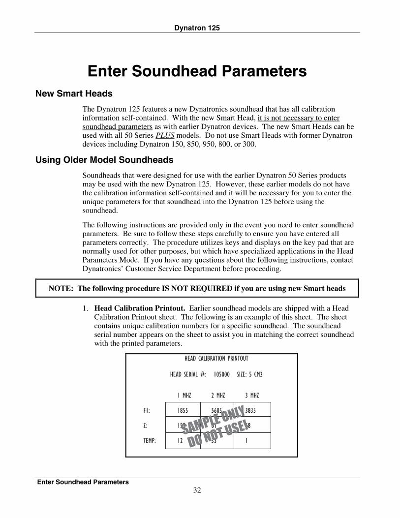
1. Head Calibration Printout. Earlier soundhead models are shipped with a Head Calibration Printout sheet. The following is an example of this sheet. The sheet contains unique calibration numbers for a specific soundhead. The soundhead serial number appears on the sheet to assist you in matching the correct soundhead with the printed parameters.
Dynatron 125
Enter Soundhead Parameters 33
NOTE: THE NUMBERS ON THE PREVIOUS PAGE ARE PROVIDED FOR ILLUSTRATION ONLY AND SHOULD NOT BE ENTERED INTO YOUR DYNATRON DEVICE. USE ONLY THE ACTUAL NUMBERS PROVIDED WITH YOUR OWN SOUNDHEAD. 2. Plug in Soundhead. Turn the Dynatron 125 off, then plug in the new soundhead. 3. Enter Head Parameters Mode. To enter the Head Parameters Mode, press and
hold the Duty Cycle toggle key (10%, 20%, 50%, Cont key) while turning the machine ON. Continue holding down the Duty Cycle toggle key until the device finishes its startup sequence.
The unit senses and displays the head size in the Power-Intensity display. For example, if “5” is displayed, it means the device senses a 5 cm2 head is plugged in.
4. Enter 1 MHz Values. You will begin by entering the 1 MHz values from the Head
Calibration Printout. Make sure that the 1 MHz LED is lighted before entering these values.
Locate the 1 MHz column on the printout. You will enter the values shown for F1, Z, and TEMP. Enter the numbers as follows:
a. Select CONT Duty Cycle: The CONT and 1 MHz LEDs are lighted. Enter the value for F1 – 1 MHz by pressing the time selection keys until the desired value is displayed in the time display.
Use the Time Selection (up/down) keys to enter the desired number. The value you enter is displayed in the TIME display. Press and hold the up or down key to move more quickly to the desired number, or press and release the key to step up or down one digit at a time.
b. Select 50% Duty Cycle: With the 50% LED lighted, enter the value for Z – 1 MHz. c. Select 20% Duty Cycle: With the CONT LED lighted, enter the value for Temp – 1 MHz. d. Select 10% Duty Cycle: With the 10% LED lighted, enter “0” (zero) as the
value for Coupling. The coupling feature is not available with old-style soundheads.
5. Enter 3 MHz Values. Press the FREQ key to select 3 MHz. Make sure the 3 MHz
LED is lighted. Locate the 3 MHz column on the printout, and enter the numbers as follows:
a. Select CONT Duty Cycle: The CONT and 3 MHz LEDs are lighted. Enter
the value for F1 – 3 MHz by pressing the time selection keys until the desired value is displayed in the time display.
b. Select 50% Duty Cycle: With the 50% LED lighted, enter the value for Z – 3 MHz.
Dynatron 125
Enter Soundhead Parameters 34
c. Select 20% Duty Cycle: With the CONT LED lighted, enter the value for Temp – 3 MHz. d. Select 10% Duty Cycle: With the 10% LED lighted, enter “0” (zero) as the
value for Coupling. The coupling feature is not available with old-style soundheads.
6. Store New Parameters. After you have entered all parameters, press START to
store them in the device’s memory. Then press STOP to exit this mode. The above procedure must be performed for each separate soundhead for the device. Turn the device off before attaching the next soundhead, then turn the device on again with the soundhead firmly plugged in.
Dynatron 125
Calibration Procedure 35
Calibration Procedure With the exception of calibration, all service on the Dynatron 125 device should be performed by a Dynatronics service technician. If your Dynatron 125 requires service, contact Dynatronics Customer Service at (800) 874-6251. The calibration procedure MUST be performed by a qualified Ultrasound technician using the proper equipment. Calibration may be performed either by Dynatronics or by an Ultrasound technician in your local area. When to Calibrate: Dynatronics recommends that the Dynatron 125 be calibrated annually to ensure the unit is working at its peak performance. What to Calibrate: You must calibrate all soundheads used for this device at both 1 and 3 MHz frequencies. Equipment Required: You will require an Ultrasound power meter capable of accurately measuring outputs up to 3 MHz. Check the manufacturer’s specifications to confirm your power meter meets this qualification. Ohmic Instrument UPM-DT1 or UPM-DT-10 are recommended for use. Water Quality: Water used in the testing procedure must be degassed water with an oxygen content of four parts per million (4ppm) or less. The following steps are provided to assist the technician with the calibration procedure. A calibration program is built into the software for the device. The procedure utilizes keys and displays on the key pad that are normally used for other purposes, but which have specialized applications in the Calibration Mode. If you have any questions about the following instructions, contact Dynatronics’ Customer Service Department before proceeding. STEPS 1. Begin with the machine turned off. Plug the soundhead to be calibrated into the
Dynatron 125 Ultrasound output jack and center the soundhead over the cone in the Ultrasound power meter.
2. Enter the Dynatron 125’s Calibration Mode by pressing and holding the PAUSE
key while turning the machine on. The display windows first show the soundhead type that is plugged into the machine (see Soundhead Type Table on next page).
Dynatron 125
Calibration Procedure 36
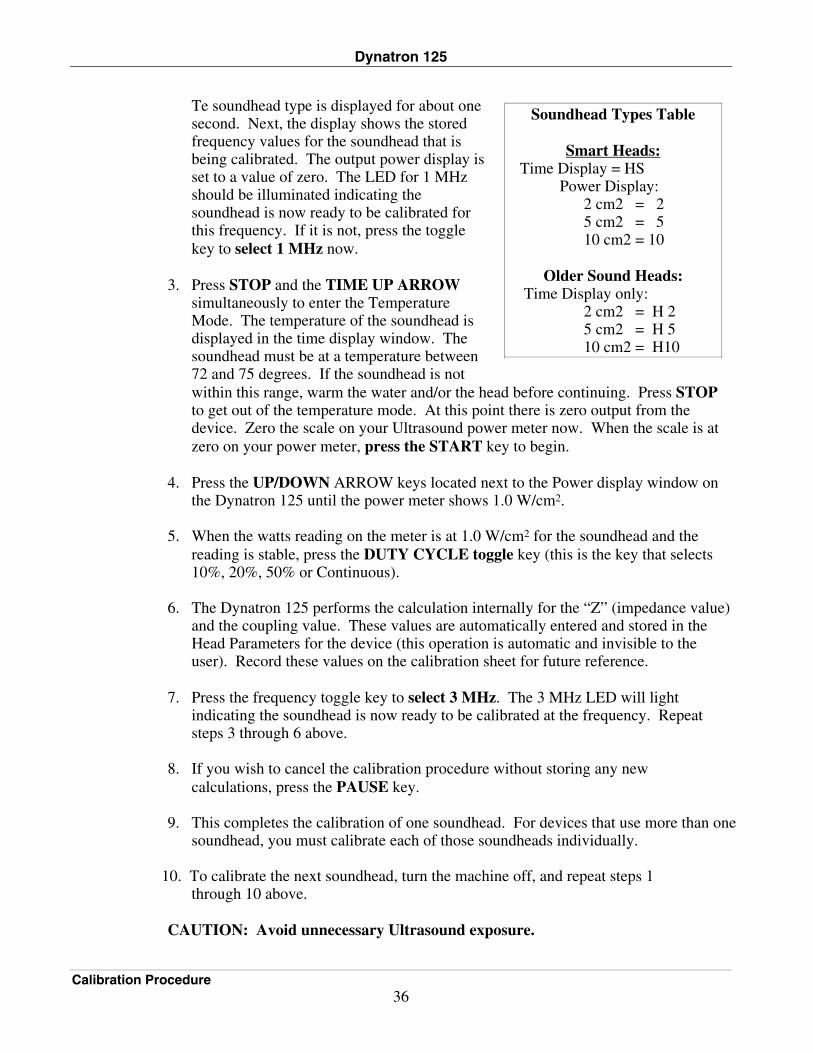
Te soundhead type is displayed for about one second. Next, the display shows the stored frequency values for the soundhead that is being calibrated. The output power display is set to a value of zero. The LED for 1 MHz should be illuminated indicating the soundhead is now ready to be calibrated for this frequency. If it is not, press the toggle key to select 1 MHz now.
3. Press STOP and the TIME UP ARROW
simultaneously to enter the Temperature Mode. The temperature of the soundhead is displayed in the time display window. The soundhead must be at a temperature between 72 and 75 degrees. If the soundhead is not within this range, warm the water and/or the head before continuing. Press STOP to get out of the temperature mode. At this point there is zero output from the device. Zero the scale on your Ultrasound power meter now. When the scale is at zero on your power meter, press the START key to begin.
4. Press the UP/DOWN ARROW keys located next to the Power display window on
the Dynatron 125 until the power meter shows 1.0 W/cm2. 5. When the watts reading on the meter is at 1.0 W/cm2 for the soundhead and the
reading is stable, press the DUTY CYCLE toggle key (this is the key that selects 10%, 20%, 50% or Continuous).
6. The Dynatron 125 performs the calculation internally for the “Z” (impedance value)
and the coupling value. These values are automatically entered and stored in the Head Parameters for the device (this operation is automatic and invisible to the user). Record these values on the calibration sheet for future reference.
7. Press the frequency toggle key to select 3 MHz. The 3 MHz LED will light
indicating the soundhead is now ready to be calibrated at the frequency. Repeat steps 3 through 6 above.
8. If you wish to cancel the calibration procedure without storing any new
calculations, press the PAUSE key. 9. This completes the calibration of one soundhead. For devices that use more than one
soundhead, you must calibrate each of those soundheads individually.
10. To calibrate the next soundhead, turn the machine off, and repeat steps 1 through 10 above. CAUTION: Avoid unnecessary Ultrasound exposure.
Soundhead Types Table
Smart Heads: Time Display = HS Power Display: 2 cm2 = 2 5 cm2 = 5 10 cm2 = 10
Older Sound Heads:
Time Display only: 2 cm2 = H 2 5 cm2 = H 5 10 cm2 = H10
Dynatron 125
Problem Solving 37
Problem Solving The following are problems that could occur with the Dynatron 125. Appropriate actions are also provided.
Soundhead Temperature Too Hot If coupling (the effective degree at which the Ultrasound is delivered from the soundhead to the patient’s body) is not adequate during treatment, the temperature of the soundhead rises (see also “Head Temperature Hot,” page 12). The Dynatron 125 uses several methods to inform the user of the temperature status throughout the treatment: • If the soundhead approaches maximum temperature, the power display begins
flashing to notify the user to improve coupling or reduce the power to prevent the soundhead from becoming too hot.
• If the soundhead reaches maximum temperature the treatment is paused; the
output is stopped, the timer is paused, and the Pause light is lighted. When the soundhead cools sufficiently, the power display and the lights on the soundhead will cease flashing. You can then press PAUSE or START to resume the treatment.
Cooling the Soundhead
The temperature alert not only ensures good coupling throughout the treatment, it helps avoid damage to the soundhead crystal. If the soundhead becomes too hot, it must be allowed to cool down before resuming the treatment. The head will cool slowly if allowed to sit at room temperature. To cool the soundhead quickly, you can place it in room temperature water. Sometimes just applying more conductive gel will adequately cool the head. Larger soundheads will take longer to cool down. DO NOT USE ICE to cool the soundhead as this can cause thermal shock to the crystal and may necessitate a costly repair. Damage caused by thermal shock is not covered under the warranty.
Whirlpool Treatments If you are treating in a whirlpool, you may find the temperature reaches a high enough temperature to cause the display to flash “105˚” (see also, Head Temperature Bar Graph, page 11). This is a warning only to let you know you are approaching the temperature limit. You may, however, continue with the treatment at this level. If your whirlpool temperature is hot enough to cause the treatment to stop, you may need to adjust the temperature of the whirlpool.
Dynatron 125
Problem Solving 38
Soundhead Temperature Too Cold
If the soundhead has been sitting in a cold room or vehicle, it could be too cold to operate when you turn the device on. The keypad may not respond to key presses and you will be unable to use the device until the soundhead is sufficiently warmed. You must raise the temperature of the soundhead to about 60 degrees F. in order for the machine to recognize that the soundhead is present and to proceed with setting up a treatment. You can accomplish this with any of the following methods:
1. Press the flat face of the soundhead against the palm of your hand for 30 to 60 seconds to warm it slightly. This usually provides adequate warmth to the crystal to raise the temperature to the minimum acceptable level. Once the crystal reaches this level, you can proceed with treatment.
2. You can also place the soundhead in room temperature water to warm the crystal. However, do not place the soundhead in very hot water when the crystal is this cold as it could damage the crystal.
Error Message in the Display
Certain conditions can cause an error in operation. When this occurs, the machine will not allow a treatment to be set up or delivered and will display an error message in the LED displays. An error message can consist of any combination of alpha-numeric characters which are not normally expected at any given point in treatment setup or delivery. Some errors are easily resolved by the following methods.
• Press STOP to stop the treatment (if any), and turn the machine off then on again.
• Check to be sure the soundhead has not become disconnected from the machine. The soundhead should be firmly plugged into its port. Only Dynatronics soundheads may be used with this device. If the soundhead has been dropped, it may be damaged. If the device operates normally with one soundhead, but not with another, the problem may be a damaged soundhead and you must contact Dynatronics Customer Service.
• Make sure the soundhead is not too hot. In this case the power LED display will flash. Any other display indicates a problem not related to a soundhead that is too hot. For hot soundheads, follow the instructions provided earlier in this section.
• Check to see if conditions may have caused moisture condensation in the device. This could occur when the machine has become very cold (for example, if left outdoors in a vehicle during winter), then is brought indoors to a warm, humid environment (such as a whirlpool room). Condensation is a not a serious condition. Allow the machine to sit in a dry environment until the condensation dries. The machine will operate normally once the condensation is gone.
If you have tried all of these suggestions, and the error is still displayed on the LEDs, the device may require service by the manufacturer. In this case, contact Dynatronics Customer Service at 1-800-874-6251 for further assistance. Do not send the device to Dynatronics without first contacting the Customer Service Department.
Dynatron 125
Sending a Unit in for Repair 39
Sending a Unit in for Repair Return Authorization
To send a unit to Dynatronics for repair, you MUST first receive authorization from Dynatronics. This authorization is represented by a Return Authorization (RA) number. An RA form is used internally at Dynatronics to help identify who is sending the unit in for repair and why. It shows customer complaint or problem information, and has the address where the unit should be shipped after repair. When a service call is received by Dynatronics, the following information must be supplied before an RA number can be issued: 1. User name and address 2. User phone number 3. Serial number of the unit 4. A description of the problem with the unit. This information is important so we may identify the problem before the unit is shipped and ensure proper handling of the repair or disposition of the unit. The user or dealer name and address, and the serial number of the unit are required before Dynatronics will issue an RA number. When the unit is received at Dynatronics, it is unpacked and inspected for shipping damage. An inventory of the parts that were sent with the unit is taken at that time and recorded on the RA sheet. Any observed damage is also noted on the sheet. The unit is then examined by a repair technician who evaluates the problems with the unit and writes observations on the RA form. The technician completes the repair, again writing the steps taken to repair the unit, listing the parts used, and recording the time taken in the repair. The technician dates and signs the form. The unit then receives a final quality assurance (QA) inspection by quality control staff member who signs the RA form indicating the QA is complete. One copy of the RA form is returned to the user with the unit. This tells the dealer and the user what was done to the unit while it was in for repair.
Why the Information is Necessary Dynatronics, like all medical manufacturing companies, is required by the FDA to keep records on all units sold. This record consists of 1) the date the unit was sold, 2) to whom it was sold, 3) any problems the customer has with that unit in the field, and 4) any information on repairs performed on the unit.
Dynatron 125
Sending a Unit in for Repair 40
The information collected also helps us improve the unit’s performance. It helps us to identify trends and allows us to pinpoint a manufacturing or engineering change that will make the unit function more reliably.
Packaging and Shipping of Replacement Parts All defective or broken parts should be shipped back to Dynatronics in the original shipping container. These containers are designed to withstand the punishment of shipping. If the original containers are not usable, find containers that are similar in protection so damage in shipping will be prevented. The person or company sending the unit to Dynatronics is responsible for any shipping damage resulting from a poorly packaged part or unit.
Dynatron 125
Assy and Test Instructions - DS009C - REV 7.1 – 11/6/03 D125 / 150 Plus/153B&G device
Installing Software Updates Features and function of this device may be updated from time to time by the manufacturer. Such updates are installed via the “COM” port on the device using a handheld download device which is available from Dynatronics. It is recommended that a Dynatronics dealer perform the software update for you. This will ensure the software update is installed successfully, and will save you the expense of purchasing the separate download device. If you have registered your product warranty with the manufacturer, you will be notified of any software updates that may become available in the future.
Installing Replacement Parts Since software updates for the Dynatron 125 are provided from an external connection, it is not necessary to replace the EPROM in the device. This device is not generally serviceable in the field. If you wish to perform any service on the device or replace any internal parts, you must first contact Dynatronics Customer Service for guidance. Keep in mind that if the device is serviced or altered by anyone except authorized Dynatronics service personnel, the warranty on the device is invalidated. For service assistance, contact Dynatronics’ Service Department at 1-800-874-6251.
Medical Device Reporting Requirements Under the Safe Medical Devices Act (SMDA) of November 1990, the manufacturer and distributor are required to report specific incidents to the FDA. In the event of any applicable incident, you should report details of the incident to the Dynatronics Customer Service Department at 1-800-874-6251. Reports should be submitted to the manufacturer immediately to allow the manufacturer to report to the FDA within 10 working days.
Dynatron 125
Installing Software Updates 42
• If you receive information that reasonably suggests a probability that a device caused or contributed to a:
- death - serious injury, or - serious illness • If you receive information that reasonably suggests a device malfunction and
a recurrence will probably cause: - death - serious injury, or - serious illness
Definition of serious injury:
A “serious injury” is an injury that (1) is life threatening, (2) results in permanent impairment of a body function or permanent damage to body structure, or (3) necessitates medical or surgical intervention by a health care professional to (i) preclude permanent impairment of a body function or permanent damage to body structure or (ii) relieve unanticipated temporary impairment of a body function or unanticipated temporary damage to a body structure. Reference: Food and Drug Administration, HHS. 21 CFR Ch. 1 (4-1-90 Edition), 803.9 (h).
Schematics and QC Check Lists The following pages provide the schematics and QC check lists for the Dynatron 125.
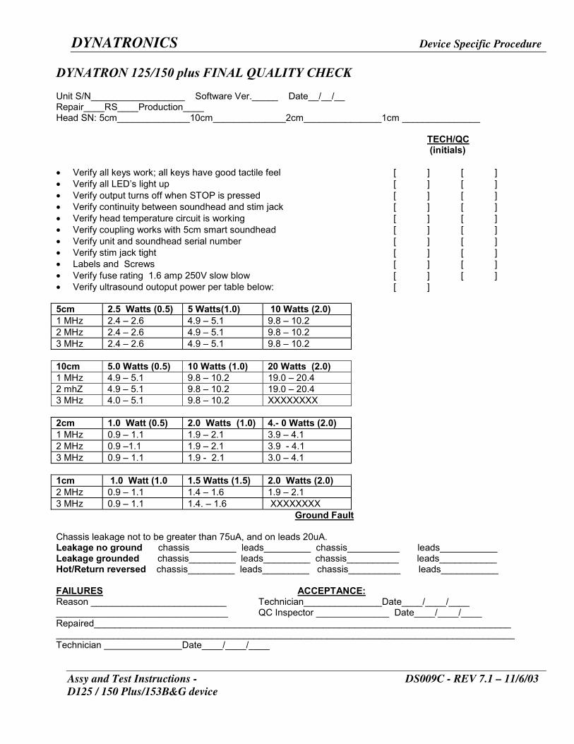
DYNATRONICS Device Specific Procedure
Assy and Test Instructions - DS009C - REV 7.1 – 11/6/03 D125 / 150 Plus/153B&G device
DYNATRON 125/150 plus FINAL QUALITY CHECK Unit S/N__________________ Software Ver._____ Date__/__/__ Repair____RS____Production____ Head SN: 5cm______________10cm______________2cm_______________1cm _______________
TECH/QC
(initials) • Verify all keys work; all keys have good tactile feel [ ] [ ] • Verify all LED’s light up [ ] [ ] • Verify output turns off when STOP is pressed [ ] [ ] • Verify continuity between soundhead and stim jack [ ] [ ] • Verify head temperature circuit is working [ ] [ ] • Verify coupling works with 5cm smart soundhead [ ] [ ] • Verify unit and soundhead serial number [ ] [ ] • Verify stim jack tight [ ] [ ] • Labels and Screws [ ] [ ] • Verify fuse rating 1.6 amp 250V slow blow [ ] [ ] • Verify ultrasound outoput power per table below: [ ] 5cm 2.5 Watts (0.5) 5 Watts(1.0) 10 Watts (2.0) 1 MHz 2.4 – 2.6 4.9 – 5.1 9.8 – 10.2 2 MHz 2.4 – 2.6 4.9 – 5.1 9.8 – 10.2 3 MHz 2.4 – 2.6 4.9 – 5.1 9.8 – 10.2 10cm 5.0 Watts (0.5) 10 Watts (1.0) 20 Watts (2.0) 1 MHz 4.9 – 5.1 9.8 – 10.2 19.0 – 20.4 2 mhZ 4.9 – 5.1 9.8 – 10.2 19.0 – 20.4 3 MHz 4.0 – 5.1 9.8 – 10.2 XXXXXXXX 2cm 1.0 Watt (0.5) 2.0 Watts (1.0) 4.- 0 Watts (2.0) 1 MHz 0.9 – 1.1 1.9 – 2.1 3.9 – 4.1 2 MHz 0.9 –1.1 1.9 – 2.1 3.9 - 4.1 3 MHz 0.9 – 1.1 1.9 - 2.1 3.0 – 4.1 1cm 1.0 Watt (1.0 1.5 Watts (1.5) 2.0 Watts (2.0) 2 MHz 0.9 – 1.1 1.4 – 1.6 1.9 – 2.1 3 MHz 0.9 – 1.1 1.4. – 1.6 XXXXXXXX Ground Fault Chassis leakage not to be greater than 75uA, and on leads 20uA. Leakage no ground chassis_________ leads_________ chassis__________ leads___________ Leakage grounded chassis_________ leads_________ chassis__________ leads___________ Hot/Return reversed chassis_________ leads_________ chassis__________ leads___________ FAILURES ACCEPTANCE: Reason __________________________ Technician_______________Date____/____/____ _________________________________ QC Inspector ______________ Date____/____/____ Repaired________________________________________________________________________________ ________________________________________________________________________________________ Technician Date____/____/____
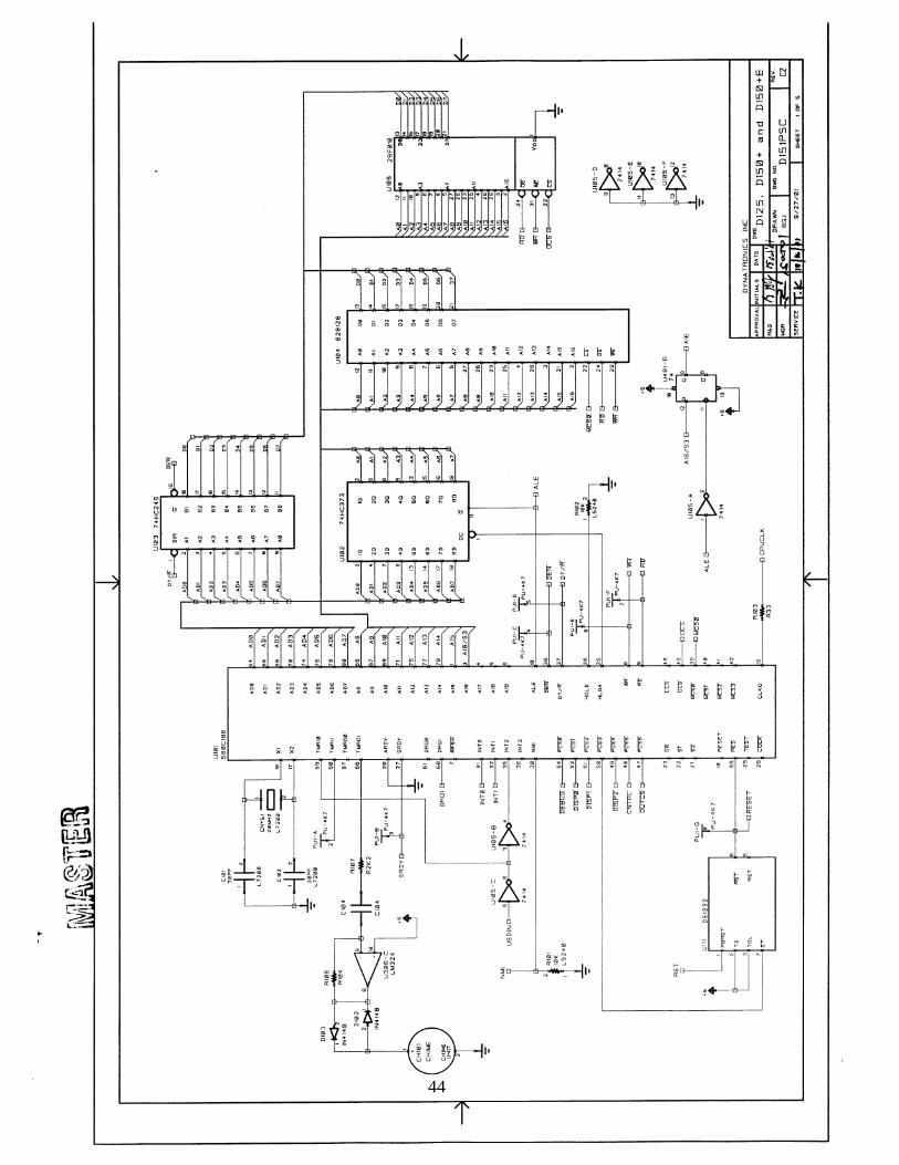
44
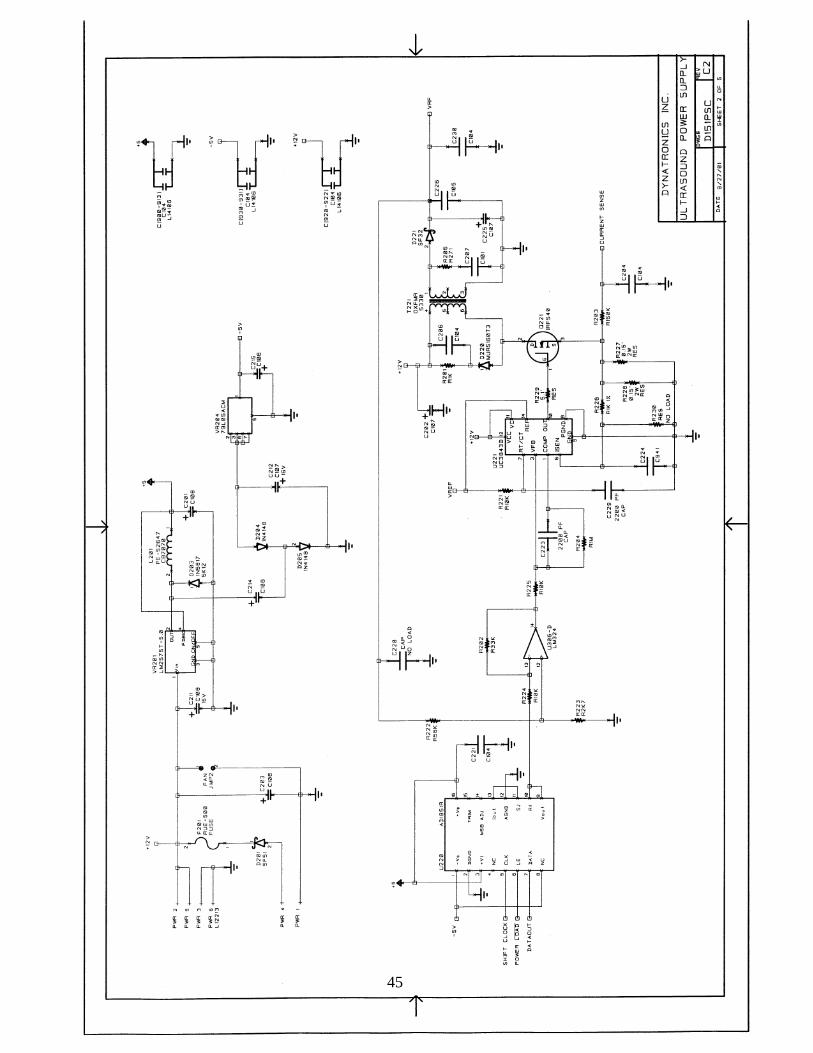
45
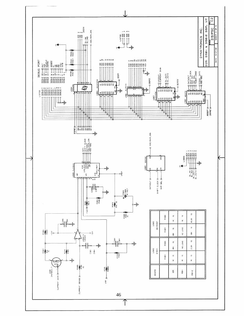
46
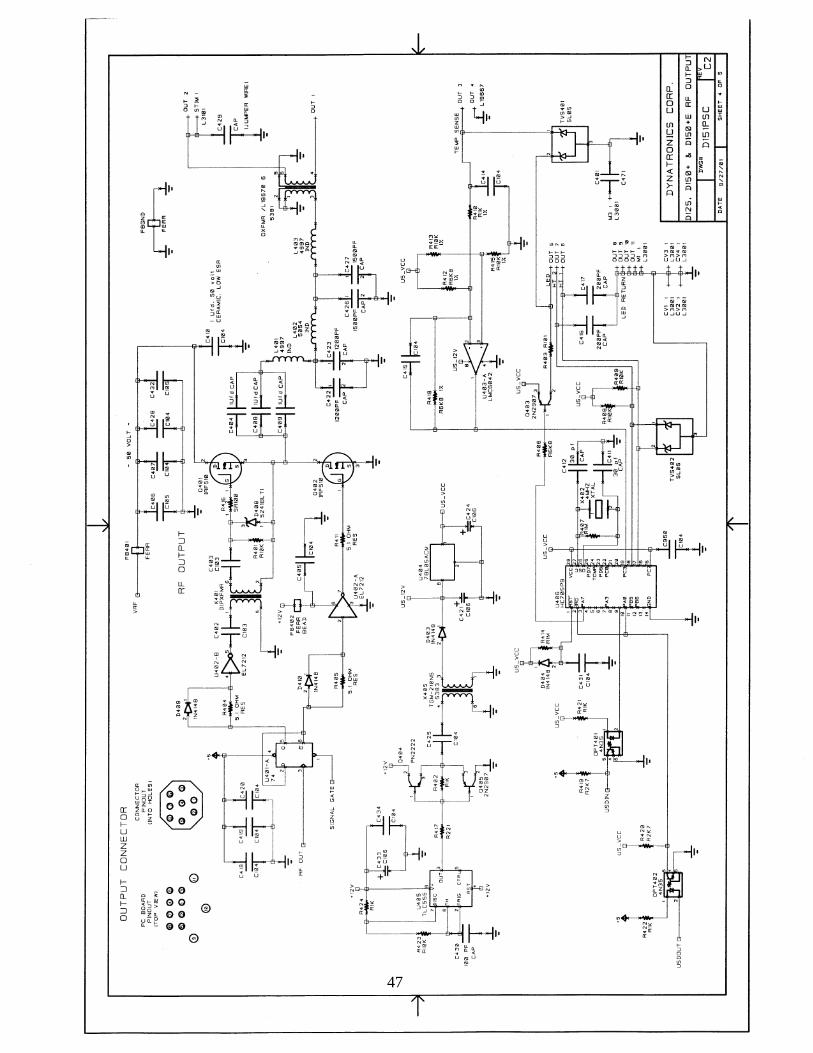
47
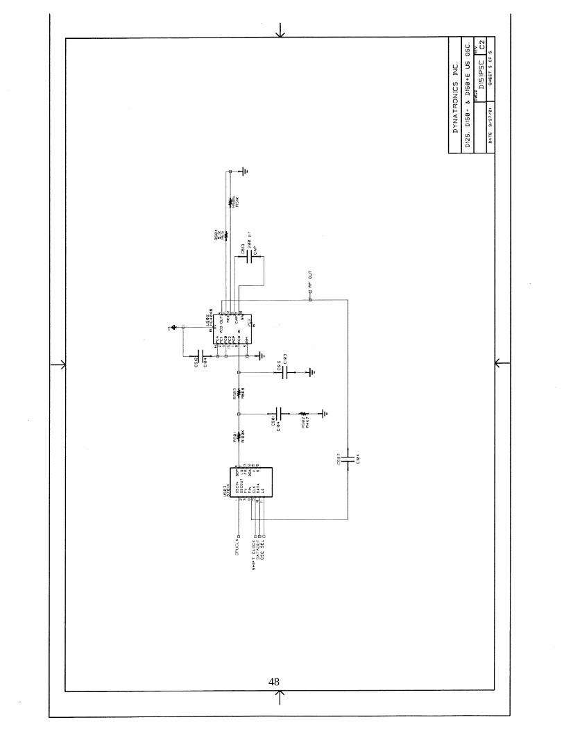
48
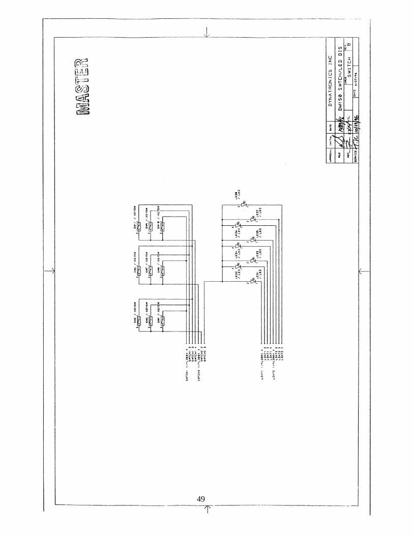
49
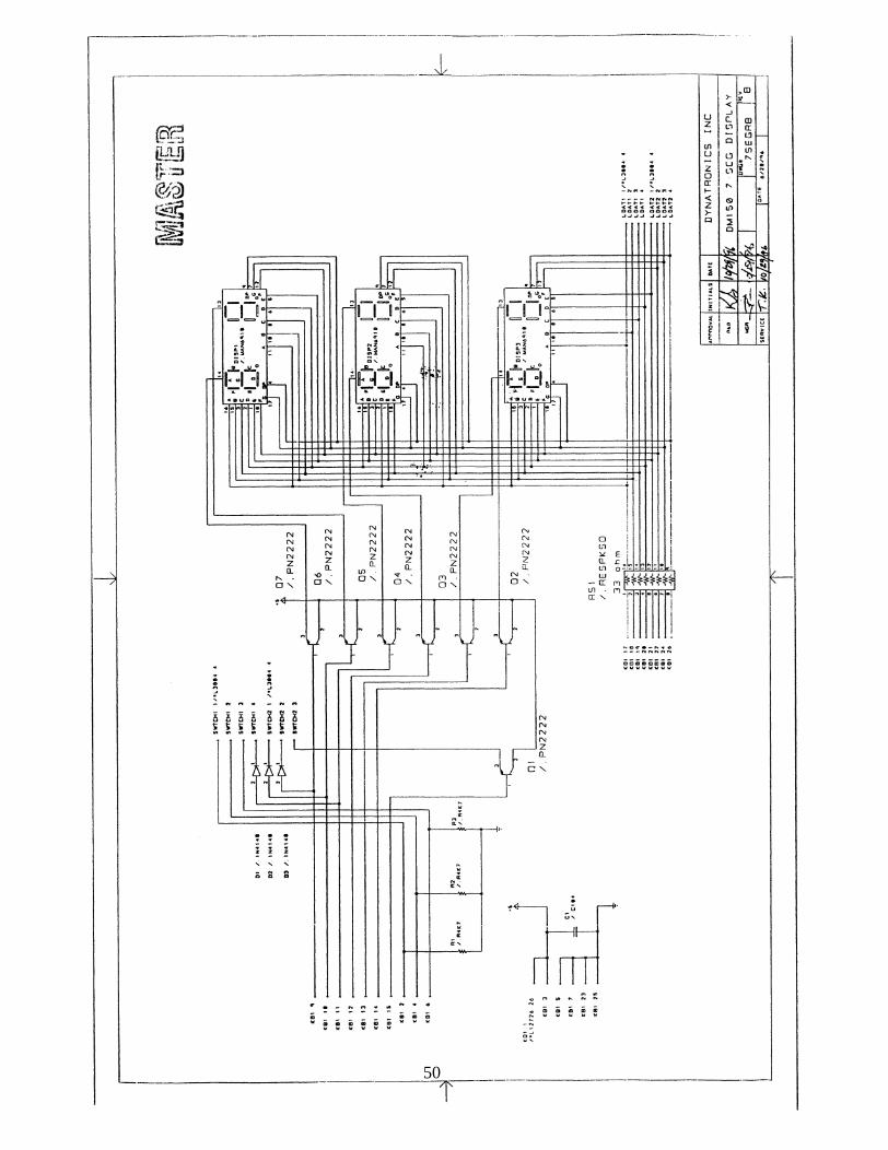
50