Embed Size (px)
Citation preview
1
This Curtis Generation 4 Unit is Factory Pre-Set and Ready to Go Right from the Box.Following are the Factory Settings for your G4 Coffee Brewing System: • Brew Temperature = 200°F • Water Bypass = On for LARGE & MEDIUM Brew Only • Brew Volume = Set to Vessel Requirement.System Requirements: • Water Source 20 – 90 PSI (Minimum Flow Rate of 1 GPM) • Electrical: See attached schematic for standard model or visit www.wilburcurtis.com for your model.
Model G4GEMS
CAUTION: DO NOT connect this brewer to hot water. The inlet valve is
not rated for hot water.
CAUTION: Please use this setup procedure before attempting to use
this brewer. Failure to follow the instructions can result in injury or the voiding of the warranty.
IMPORTANT: Equipment to be installed to comply with applicable govern-
mental plumbing/electrical codes having jurisdiction.
ISO 9001:2008 REGISTERED
WILBUR CURTIS CO., INC.6913 West Acco Street
Montebello, CA 90640-5403For the latest information go to
www.wilburcurtis.comTel: 800-421-6150Fax: 323-837-2410
For the latest specifications and information go to www.wilburcurtis.com
This equipment is designed for commercial use. Any servicing other than cleaning and routine maintenance should be performed by an authorized Wilbur Curtis Company Service Technician. • DONOTimmersetheunitinwateroranyotherliquid • Toreducetheriskoffireorelectricshock,DONOTopenservicepanels.Therearenouserserviceable parts inside. • Keephandsandotheritemsawayfromhotareasoftheunitduringoperation. • Nevercleanwithscouringpowdersorharshchemicals.
Important Safeguards/SymbolsService Manual – G4 Gem Single Head Brewer
Wilbur Curtis Company, inC.
Symbols:
WARNINGS – To help avoid personal injury
Important Notes/Cautions – from the factory
Sanitation Requirements
NSF International requires the following water connection:1. A quick disconnect or additional coiled tubing (at least 2x the depth of the unit) is required so
that the unit can be moved for cleaning.2. This unit must be installed with adequate backflow protection to comply with applicable federal,
state and local codes.3. Water pipe connections and fixtures directly connected to a portable water supply shall be sized,
installed and maintained in accordance with federal, state, and local codes.
3. Connect the unit to an electrical outlet with appropriate amperage rating (see serial tag on machine).4.Oncepowerhasbeensuppliedtotheunit,flipthetoggleswitchtothe‘ON’position(locatedontherearof
theunit),thewatertankwillbegintofill.Whenthewaterlevelinthetankreachestheprobe,theheatingelement(s) will turn on.
5. Water in theheating tankwill requireapproximatelyahalfhourbefore reachingoperating temperature(factorysettingof200°F).Whereapplicable,turnontheUniversalControlModule(UCM).Whentheunitreachesoperatingtemperature,itwilldisplay“READYTOBREW”.
NOTE:Awaterfiltrationsystemmustbeusedtohelpmaintaintrouble-freeoperation.Air must be purged from the cartridge prior to connection to equipment.Inareaswithextremelyhardwater,wehighlyrecommendtheuseofaCurtisapprovedwaterfilter.Forourfulllineoffilters,pleaselogon to www.wilburcurtis.com.
SETUP STEPS1.Theunitshouldbelevel(lefttoright-fronttoback),onasecuresurface.2. Connectthewaterlinetothewaterinletfittingontherearoftheunit.Watervolumeflowtothemachine
shouldbeconsistent.Usetubingsizedsufficientlytoprovideaminimumflowrateofonegallonperminute.
2
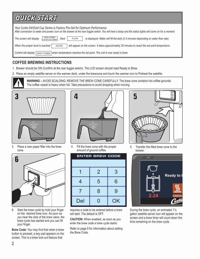
1.BrewershouldbeON(Confirmatthereartoggleswitch).TheLCDscreenshouldreadReadytoBrew.2.Placeanemptysatelliteserveronthewarmerdeck,underthebrewconeandtouchthewarmericontoPreheatthesatellite.
COFFEE BREWING INSTRUCTIONS
6. Startthebrewcyclebyholdyourfingeron the desired brew icon. As soon as youheartheclickofthebrewvalve,thebrew cycle has started and you can lift yourfinger.
Brew Code: Youmayfindthatwhenabrewbuttonispressed,akeypadappearsonthescreen.Thisisabrewlock-outfeaturethat
5. Transferthefilledbrewconetothebrewer.
3. Placeanewpaperfilterintothebrewcone.
4. Fill the brew cone with the proper amount of ground coffee.
WARNING – AVOIDSCALDING:REMOVETHEBREWCONECAREFULLY.Thebrewconecontainshotcoffeegrounds.Thecoffeevesselisheavywhenfull.Takeprecautionstoavoiddroppingwhenmoving.
requires a code to be entered before a brew will start. The default is OFF. CAUTION: Whenenabled,assoonasyouenter the brew code a brew cycle starts.Refer to page 8 for information about setting theBrewCode.
Duringthebrewcycle,ananimated1½ gallon satellite server icon will appear on the screen and a brew timer will count down the time remaining on the brew cycle.
Your Curtis G4/Gold Cup Series is Factory Pre-Set for Optimum Performance.After connection to water and power; turn on the brewer at the rear toggle switch. You will hear a beep and the status lights will come on for a moment.
The screen will display . Next is displayed. Water will fill the tank (2-3 minutes depending on water flow rate).
When the proper level is reached will appear on the screen. It takes approximately 30 minutes to reach the set point temperature.
Control will display when temperature reaches the set point. The unit is now ready to brew.
MODEL NUMBERCONTROL BD NUMBER
READY TO BREW
HEATING
FILLING
3
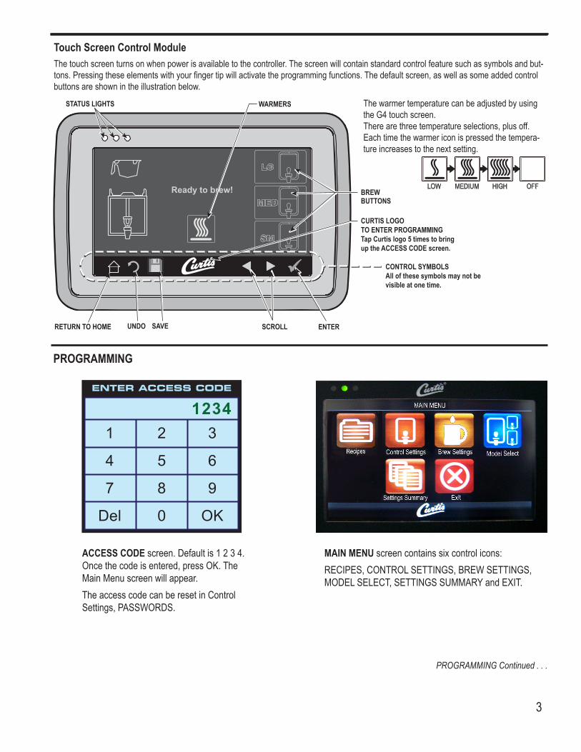
Touch Screen Control ModuleThe touch screen turns on when power is available to the controller. The screen will contain standard control feature such as symbols and but-tons.Pressingtheseelementswithyourfingertipwillactivatetheprogrammingfunctions.Thedefaultscreen,aswellassomeaddedcontrolbuttons are shown in the illustration below.
STATUS LIGHTS
BREW BUTTONS
CURTIS LOGOTO ENTER PROGRAMMINGTap Curtis logo 5 times to bring up the ACCESS CODE screen.
RETURN TO HOME SCROLL ENTER
WARMERS
CONTROL SYMBOLSAll of these symbols may not be visible at one time.
SAVEUNDO
The warmer temperature can be adjusted by using theG4touchscreen.Therearethreetemperatureselections,plusoff.Each time the warmer icon is pressed the tempera-tureincreasestothenextsetting.
MAIN MENUscreencontainssixcontrolicons:RECIPES,CONTROLSETTINGS,BREWSETTINGS,MODELSELECT,SETTINGSSUMMARYandEXIT.
ACCESS CODE screen. Default is 1 2 3 4. Oncethecodeisentered,pressOK.TheMain Menu screen will appear.The access code can be reset in Control Settings,PASSWORDS.
PROGRAMMING
PROGRAMMING Continued . . .
4
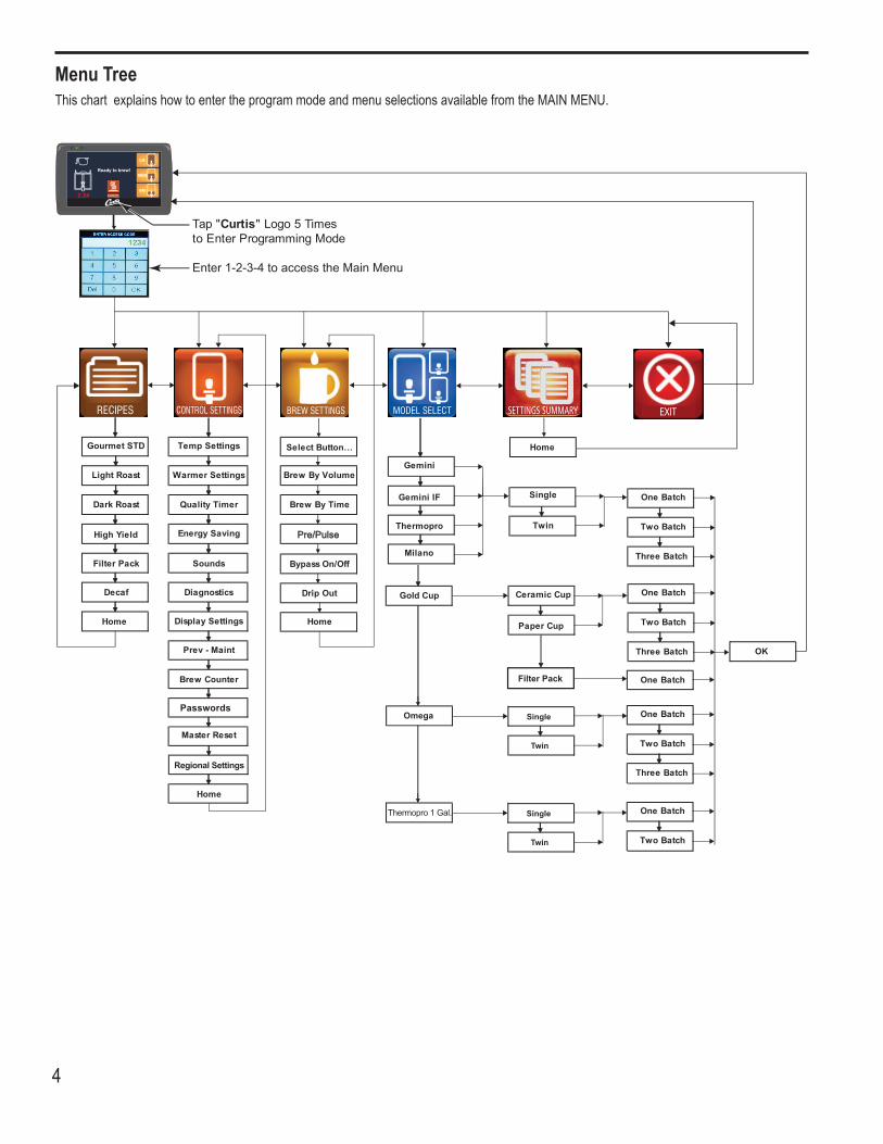
Menu TreeThischartexplainshowtoentertheprogrammodeandmenuselectionsavailablefromtheMAINMENU.
5
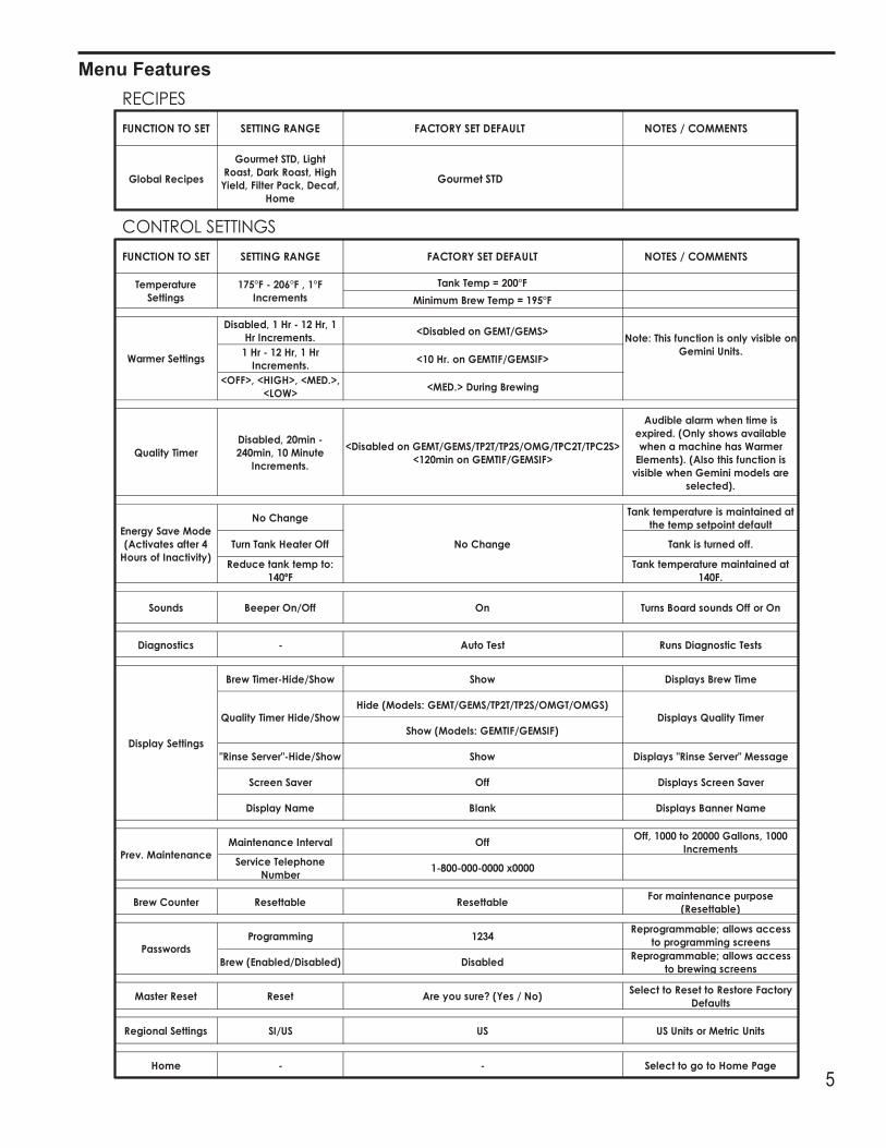
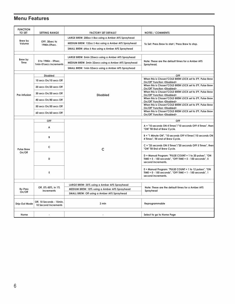
Menu Features
6
Menu Features
7
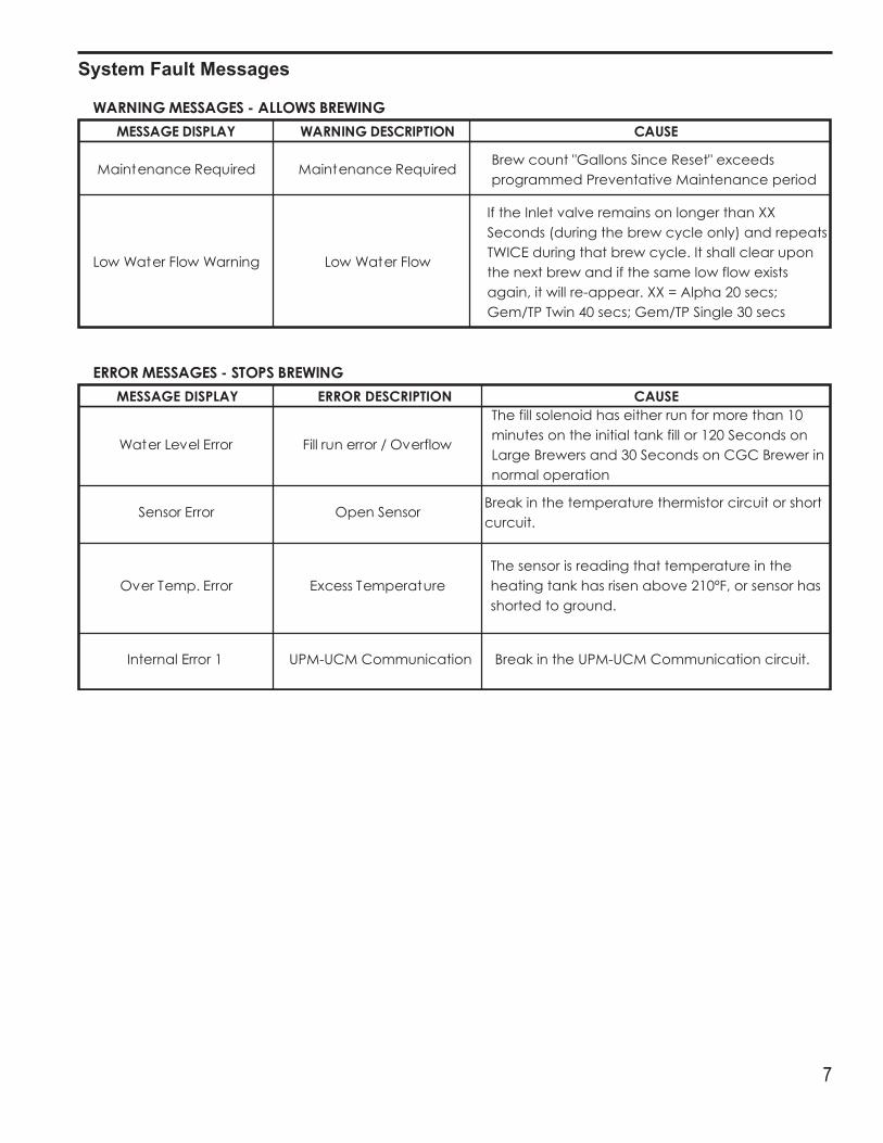
System Fault Messages
8
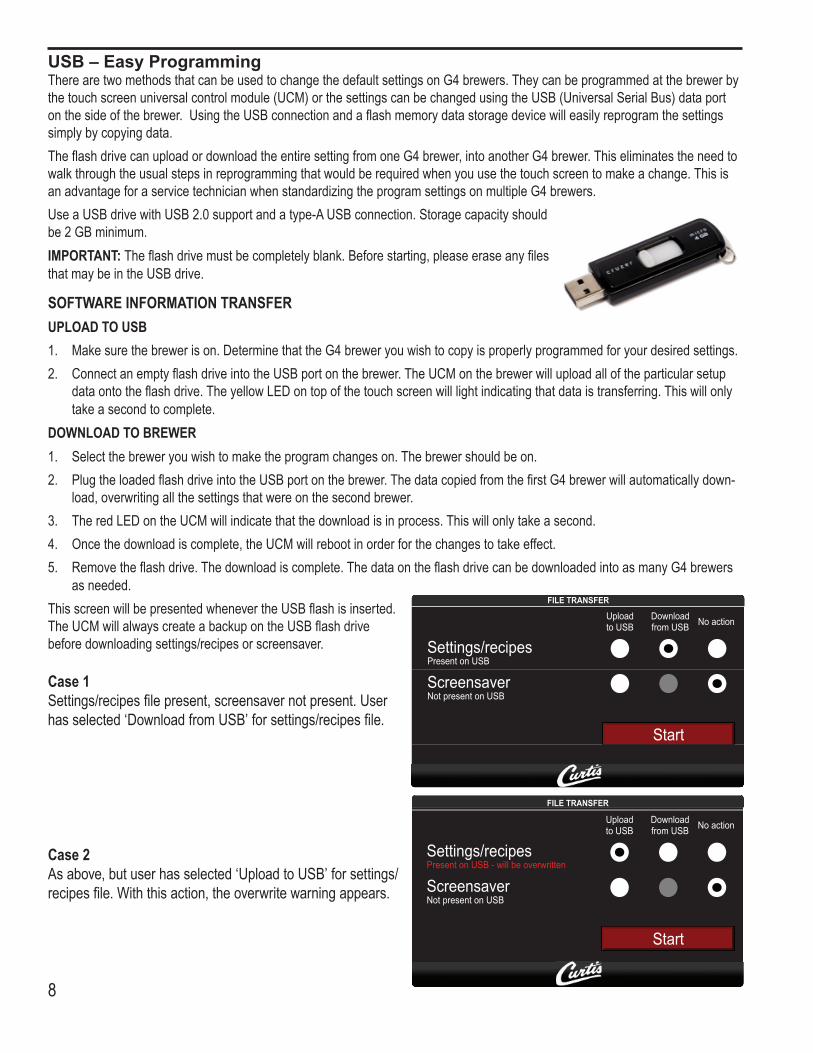
TherearetwomethodsthatcanbeusedtochangethedefaultsettingsonG4brewers.Theycanbeprogrammedatthebrewerbythetouchscreenuniversalcontrolmodule(UCM)orthesettingscanbechangedusingtheUSB(UniversalSerialBus)dataportonthesideofthebrewer.UsingtheUSBconnectionandaflashmemorydatastoragedevicewilleasilyreprogramthesettingssimply by copying data. TheflashdrivecanuploadordownloadtheentiresettingfromoneG4brewer,intoanotherG4brewer.Thiseliminatestheneedtowalkthroughtheusualstepsinreprogrammingthatwouldberequiredwhenyouusethetouchscreentomakeachange.ThisisanadvantageforaservicetechnicianwhenstandardizingtheprogramsettingsonmultipleG4brewers.UseaUSBdrivewithUSB2.0supportandatype-AUSBconnection.Storagecapacityshouldbe2GBminimum.IMPORTANT: Theflashdrivemustbecompletelyblank.Beforestarting,pleaseeraseanyfilesthatmaybeintheUSBdrive.
SOFTWARE INFORMATION TRANSFERUPLOAD TO USB1. Makesurethebrewerison.DeterminethattheG4breweryouwishtocopyisproperlyprogrammedforyourdesiredsettings.2. ConnectanemptyflashdriveintotheUSBportonthebrewer.TheUCMonthebrewerwilluploadalloftheparticularsetup
dataontotheflashdrive.TheyellowLEDontopofthetouchscreenwilllightindicatingthatdataistransferring.Thiswillonlytakeasecondtocomplete.
DOWNLOAD TO BREWER1. Selectthebreweryouwishtomaketheprogramchangeson.Thebrewershouldbeon.2. PlugtheloadedflashdriveintotheUSBportonthebrewer.ThedatacopiedfromthefirstG4brewerwillautomaticallydown-
load,overwritingallthesettingsthatwereonthesecondbrewer.3. TheredLEDontheUCMwillindicatethatthedownloadisinprocess.Thiswillonlytakeasecond.4. Oncethedownloadiscomplete,theUCMwillrebootinorderforthechangestotakeeffect.5. Removetheflashdrive.Thedownloadiscomplete.ThedataontheflashdrivecanbedownloadedintoasmanyG4brewers
as needed.
USB – Easy Programming
ThisscreenwillbepresentedwhenevertheUSBflashisinserted.TheUCMwillalwayscreateabackupontheUSBflashdrivebefore downloading settings/recipes or screensaver.
Case 1 Settings/recipesfilepresent,screensavernotpresent.Userhasselected‘DownloadfromUSB’forsettings/recipesfile.
Case 2Asabove,butuserhasselected‘UploadtoUSB’forsettings/recipesfile.Withthisaction,theoverwritewarningappears.
9
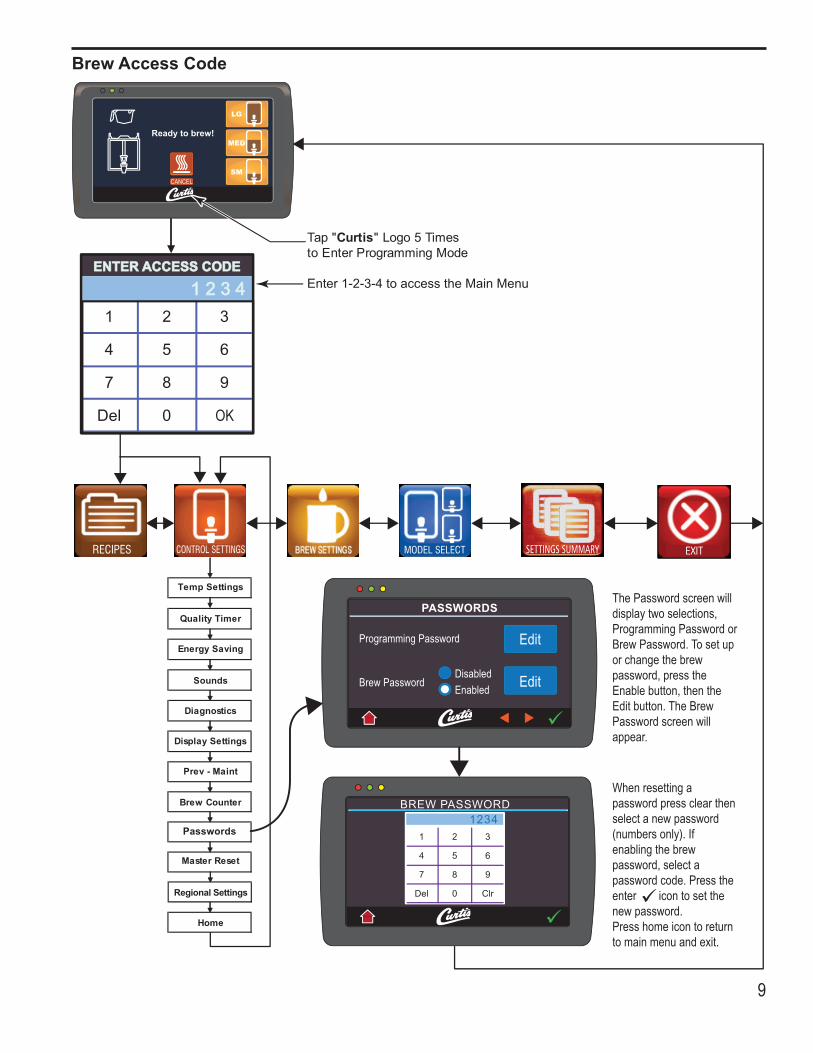
Brew Access Code
10
1
2
3
4
5
6
7
8
9
10
11
12
13
14
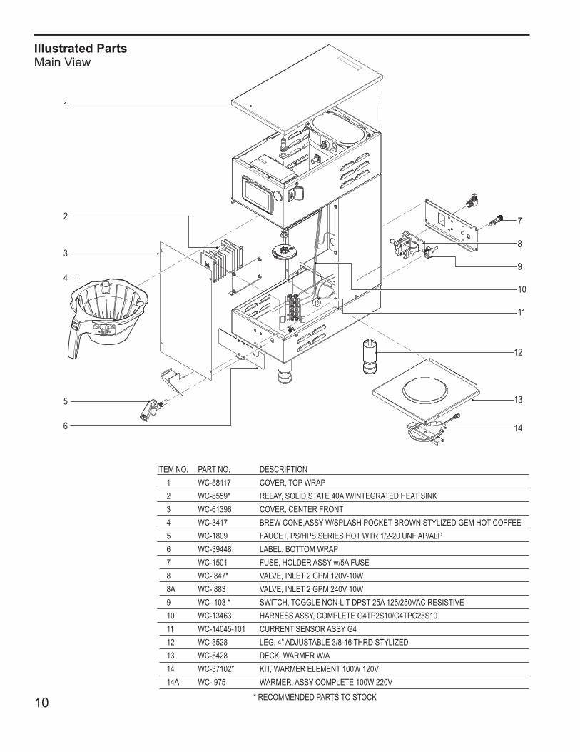
ITEM NO. PART NO. DESCRIPTION1 WC-58117 COVER,TOPWRAP2 WC-8559* RELAY,SOLIDSTATE40AW/INTEGRATEDHEATSINK3 WC-61396 COVER,CENTERFRONT4 WC-3417 BREWCONE,ASSYW/SPLASHPOCKETBROWNSTYLIZEDGEMHOTCOFFEE5 WC-1809 FAUCET,PS/HPSSERIESHOTWTR1/2-20UNFAP/ALP6 WC-39448 LABEL,BOTTOMWRAP7 WC-1501 FUSE,HOLDERASSYw/5AFUSE8 WC-847* VALVE,INLET2GPM120V-10W8A WC-883 VALVE,INLET2GPM240V10W9 WC-103* SWITCH,TOGGLENON-LITDPST25A125/250VACRESISTIVE10 WC-13463 HARNESSASSY,COMPLETEG4TP2S10/G4TPC25S1011 WC-14045-101 CURRENTSENSORASSYG412 WC-3528 LEG,4”ADJUSTABLE3/8-16THRDSTYLIZED13 WC-5428 DECK,WARMERW/A14 WC-37102* KIT,WARMERELEMENT100W120V14A WC-975 WARMER,ASSYCOMPLETE100W220V
*RECOMMENDEDPARTSTOSTOCK
Illustrated PartsMain View
11
15
16
17
18
19
20
21
22
23
24
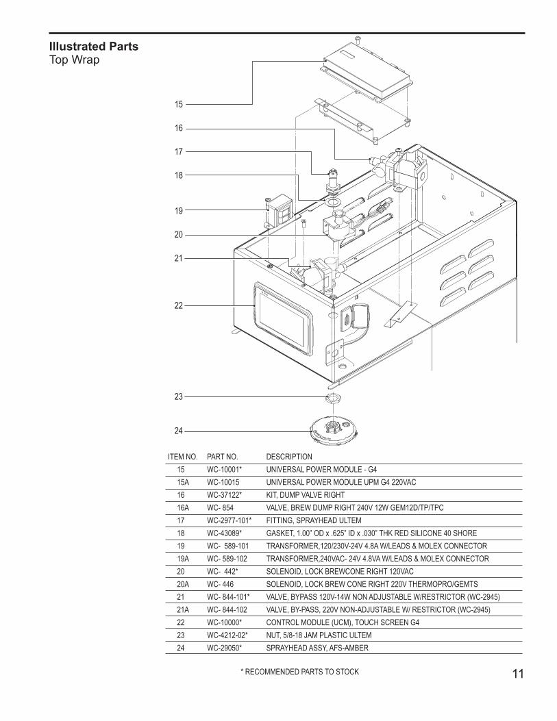
ITEM NO. PART NO. DESCRIPTION15 WC-10001* UNIVERSALPOWERMODULE-G415A WC-10015 UNIVERSALPOWERMODULEUPMG4220VAC16 WC-37122* KIT,DUMPVALVERIGHT16A WC-854 VALVE,BREWDUMPRIGHT240V12WGEM12D/TP/TPC17 WC-2977-101* FITTING,SPRAYHEADULTEM18 WC-43089* GASKET,1.00”ODx.625”IDx.030”THKREDSILICONE40SHORE19 WC-589-101 TRANSFORMER,120/230V-24V4.8AW/LEADS&MOLEXCONNECTOR19A WC-589-102 TRANSFORMER,240VAC-24V4.8VAW/LEADS&MOLEXCONNECTOR20 WC-442* SOLENOID,LOCKBREWCONERIGHT120VAC20A WC-446 SOLENOID,LOCKBREWCONERIGHT220VTHERMOPRO/GEMTS21 WC-844-101* VALVE,BYPASS120V-14WNONADJUSTABLEW/RESTRICTOR(WC-2945)21A WC-844-102 VALVE,BY-PASS,220VNON-ADJUSTABLEW/RESTRICTOR(WC-2945)22 WC-10000* CONTROLMODULE(UCM),TOUCHSCREENG423 WC-4212-02* NUT,5/8-18JAMPLASTICULTEM24 WC-29050* SPRAYHEADASSY,AFS-AMBER
*RECOMMENDEDPARTSTOSTOCK
Illustrated PartsTop Wrap
12
24
25
26
27
28
29
30
31
32
33
34
35
36
37
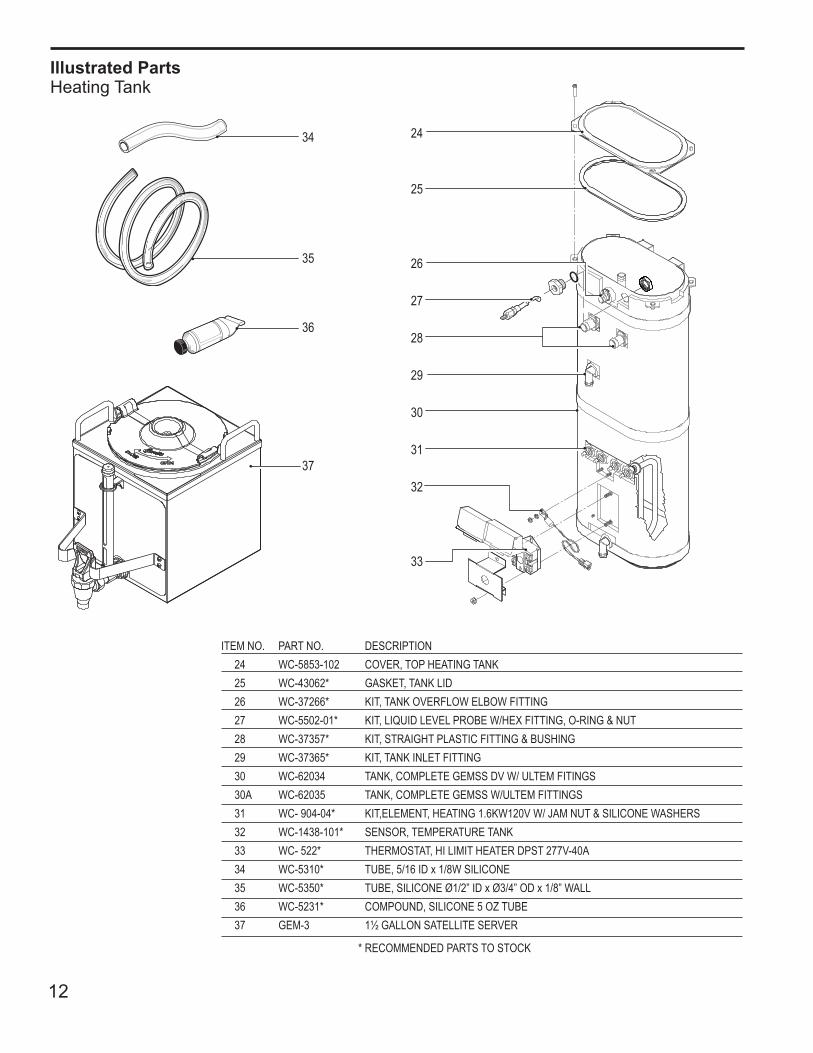
ITEM NO. PART NO. DESCRIPTION24 WC-5853-102 COVER,TOPHEATINGTANK25 WC-43062* GASKET,TANKLID26 WC-37266* KIT,TANKOVERFLOWELBOWFITTING27 WC-5502-01* KIT,LIQUIDLEVELPROBEW/HEXFITTING,O-RING&NUT28 WC-37357* KIT,STRAIGHTPLASTICFITTING&BUSHING 29 WC-37365* KIT,TANKINLETFITTING30 WC-62034 TANK,COMPLETEGEMSSDVW/ULTEMFITINGS30A WC-62035 TANK,COMPLETEGEMSSW/ULTEMFITTINGS31 WC-904-04* KIT,ELEMENT,HEATING1.6KW120VW/JAMNUT&SILICONEWASHERS32 WC-1438-101* SENSOR,TEMPERATURETANK33 WC-522* THERMOSTAT,HILIMITHEATERDPST277V-40A34 WC-5310* TUBE,5/16IDx1/8WSILICONE35 WC-5350* TUBE,SILICONEØ1/2”IDxØ3/4”ODx1/8”WALL36 WC-5231* COMPOUND,SILICONE5OZTUBE37 GEM-3 1½GALLONSATELLITESERVER
*RECOMMENDEDPARTSTOSTOCK
Illustrated PartsHeating Tank
13
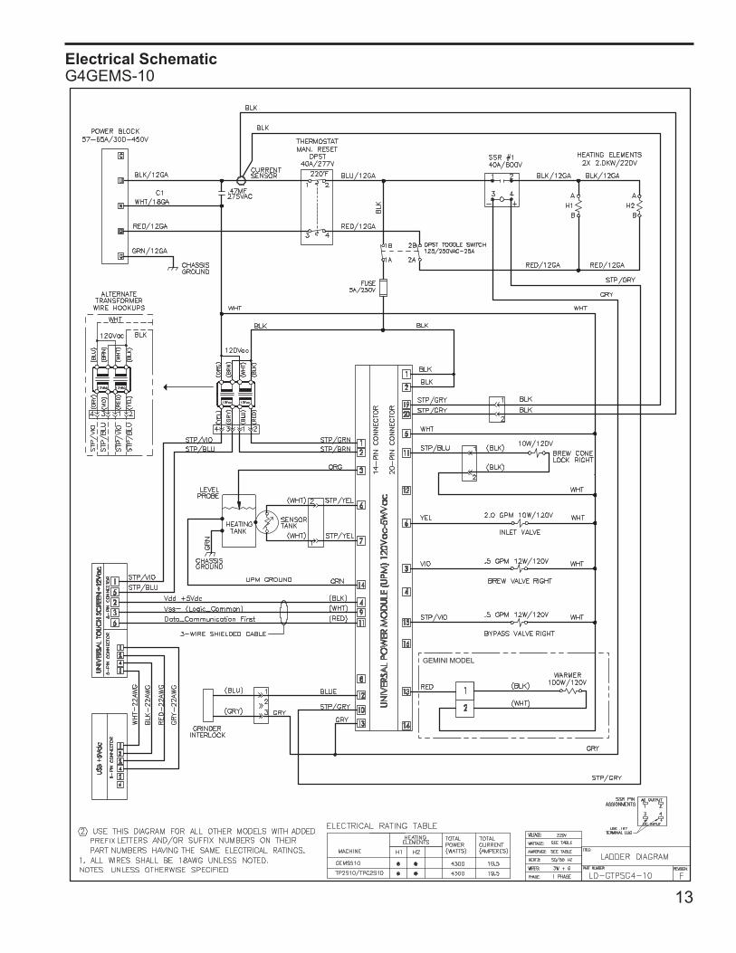
Electrical SchematicG4GEMS-10
14
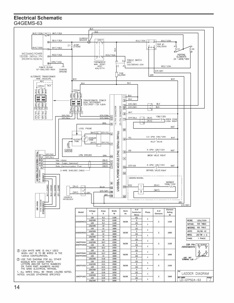
Electrical SchematicG4GEMS-63
15
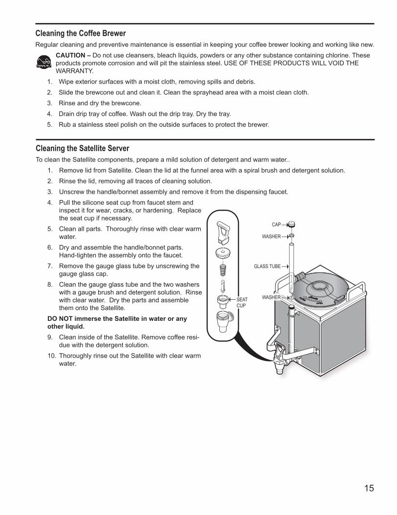
CAP
WASHER
GLASS TUBE
WASHERSEATCUP
Cleaning the Satellite ServerTo clean the Satellite components, prepare a mild solution of detergent and warm water..
1. Remove lid from Satellite. Clean the lid at the funnel area with a spiral brush and detergent solution. 2. Rinse the lid, removing all traces of cleaning solution.3. Unscrew the handle/bonnet assembly and remove it from the dispensing faucet.4. Pull the silicone seat cup from faucet stem and
inspect it for wear, cracks, or hardening. Replace the seat cup if necessary.
5. Clean all parts. Thoroughly rinse with clear warm water.
6. Dry and assemble the handle/bonnet parts. Hand-tighten the assembly onto the faucet.
7. Remove the gauge glass tube by unscrewing the gauge glass cap.
8. Clean the gauge glass tube and the two washers with a gauge brush and detergent solution. Rinse with clear water. Dry the parts and assemble them onto the Satellite.
DO NOT immerse the Satellite in water or any other liquid.9. Clean inside of the Satellite. Remove coffee resi-
due with the detergent solution.10. Thoroughly rinse out the Satellite with clear warm
water.
Cleaning the Coffee BrewerRegular cleaning and preventive maintenance is essential in keeping your coffee brewer looking and working like new.
CAUTION – Do not use cleansers, bleach liquids, powders or any other substance containing chlorine. These products promote corrosion and will pit the stainless steel. USE OF THESE PRODUCTS WILL VOID THE WARRANTY.
1. Wipe exterior surfaces with a moist cloth, removing spills and debris.2. Slide the brewcone out and clean it. Clean the sprayhead area with a moist clean cloth.3. Rinse and dry the brewcone.4. Drain drip tray of coffee. Wash out the drip tray. Dry the tray.5. Rub a stainless steel polish on the outside surfaces to protect the brewer.
16
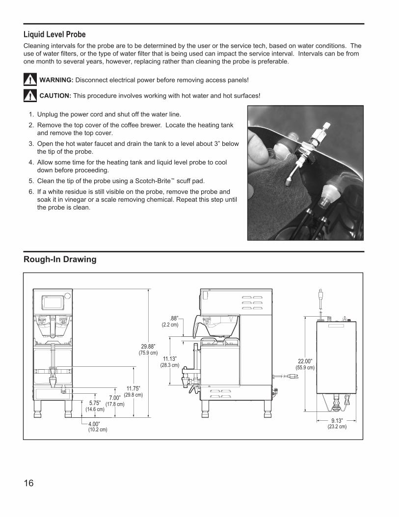
Rough-In Drawing
Liquid Level ProbeCleaning intervals for the probe are to be determined by the user or the service tech, based on water conditions. The use of water filters, or the type of water filter that is being used can impact the service interval. Intervals can be from one month to several years, however, replacing rather than cleaning the probe is preferable.
WARNING: Disconnect electrical power before removing access panels!
CAUTION: This procedure involves working with hot water and hot surfaces!
1. Unplug the power cord and shut off the water line.2. Remove the top cover of the coffee brewer. Locate the heating tank
and remove the top cover.3. Open the hot water faucet and drain the tank to a level about 3” below
the tip of the probe.4. Allow some time for the heating tank and liquid level probe to cool
down before proceeding.5. Clean the tip of the probe using a Scotch-Brite™ scuff pad. 6. If a white residue is still visible on the probe, remove the probe and
soak it in vinegar or a scale removing chemical. Repeat this step until the probe is clean.

17
Page Intentionally Left Blank
ECN 15688 . 4/8/[email protected] . rev EECN 15560 . 12/31/13 @ 7.8 . rev DECN 15339 . 9/18/13 @ 10.8 . rev CECN [email protected]/7/[email protected] . EDR 8034 . EAR 10106
Product Warranty InformationTheWilburCurtisCompanycertifiesthatitsproductsarefreefromdefectsinmaterialandworkmanshipundernormaluse.Thefollowinglimitedwarranties and conditions apply:
3 Years,PartsandLabor,fromOriginalDateofPurchaseondigitalcontrolboards.2 Years,Parts,fromOriginalDateofPurchaseonallotherelectricalcomponents,fittingsandtubing.
1 Year,Labor,fromOriginalDateofPurchaseonallelectricalcomponents,fittingsandtubing.
Additionally, theWilburCurtisCompanywarrants itsGrindingBurrsforForty(40)monthsfromdateofpurchaseor40,000poundsofcoffee,whichevercomesfirst.StainlessSteelcomponentsarewarrantedfortwo(2)yearsfromdateofpurchaseagainstleakingorpittingandreplace-ment parts are warranted for ninety (90) days from date of purchase or for the remainder of the limited warranty period of the equipment in which the component is installed.Allin-warrantyservicecallsmusthavepriorauthorization.ForAuthorization,calltheTechnicalSupportDepartmentat1-800-995-0417.EffectivedateofthispolicyisApril1,2003.Additionalconditionsmayapply.Gotowww.wilburcurtis.com to view the full product warranty information.
CONDITIONS & EXCEPTIONSThewarrantycoversoriginalequipmentattimeofpurchaseonly.TheWilburCurtisCompany,Inc.,assumesnoresponsibilityforsubstitutereplace-ment parts installed on Curtis equipment that have not been purchased from theWilburCurtisCompany,Inc.TheWilburCurtisCompanywillnotacceptanyresponsibilityifthefollowingconditionsarenotmet.Thewarrantydoes not cover and is void under the following circumstances:
1) Improper operation of equipment: The equipment must be used for its designed and intended purpose and function.2) Improper installation of equipment: This equipment must be installed by a professional technician and must comply with all local electrical,
mechanical and plumbing codes.3) Improper voltage: Equipment must be installed at the voltage stated on the serial plate supplied with this equipment.4) Improper water supply: This includes, but is not limited to, excessive or low water pressure, and inadequate or fluctuating water flow
rate.5) Adjustments and cleaning: The resetting of safety thermostats and circuit breakers, programming and temperature adjustments are the
responsibility of the equipment owner. The owner is responsible for proper cleaning and regular maintenance of this equipment.6) Damaged in transit: Equipment damaged in transit is the responsibility of the freight company and a claim should be made with the car-
rier. 7) Abuse or neglect (including failure to periodically clean or remove lime accumulations): Manufacturer is not responsible for variation
in equipment operation due to excessive lime or local water conditions. The equipment must be maintained according to the manufacturer’s recommendations.
8) Replacement of items subject to normal use and wear: This shall include, but is not limited to, light bulbs, shear disks, “0” rings, gaskets, silicone tube, canister assemblies, whipper chambers and plates, mixing bowls, agitation assemblies and whipper propellers.
9) Repairs and/or Replacements are subject to our decision that the workmanship or parts were faulty and the defects showed up under normal use. All labor shall be performed during regular working hours. Overtime charges are the responsibility of the owner. Charges incurred by delays, waiting time, or operating restrictions that hinder the service technician’s ability to perform service is the responsibility of the owner of the equipment. This includes institutional and correctional facilities. The Wilbur Curtis Company will allow up to 100 miles, round trip, per in-warranty service call.
RETURN MERCHANDISE AUTHORIZATION: All claims under this warranty must be submitted to the Wilbur Curtis Company Technical Support Department prior to performing any repair work or return of this equipment to the factory. All returned equipment must be repackaged properly in the original carton. No units will be accepted if they are damaged in transit due to improper packaging. NO UNITS OR PARTS WILL BE ACCEPTED WITHOUT A RETURN MERCHANDISE AUTHORIZATION (RMA). RMA NUMBER MUST BE MARKED ON THE CARTON OR SHIPPING LABEL. All in-warranty service calls must be performed by an authorized service agent. Call the Wilbur Curtis Technical Sup-portDepartmenttofindanagentnearyou.
4/2014 . F-3842 rev E
WILBUR CURTIS CO., INC.6913 Acco St., Montebello, CA 90640-5403 USAPhone: 800/421-6150 Fax: 323-837-2410Technical Support Phone: 800/995-0417 (M-F 5:30A - 4:00P PST) E-Mail: [email protected] Site: www.wilburcurtis.com