Embed Size (px)
Citation preview

SERVICE MANUAL DATASETTE
MODEL C2N/1530/1531
Preliminary
OCT. 1984 PN-314002-02
The Commodore Datasette has undergone many changes both in physical appearance and electronic circuitry. This preliminary package is an attempt to cover as many different versions as possible. If you need information for a version of Commodore Datasette not covered, please write to Service Documentation, Box C-2654, West Chester, PA 19380. Be sure to include an accurate description of the datasette in need of repair.
Commodore Business Machines, Inc. 1200 Wilson Drive, West Chester, Pennsylvania 19380 U.S.A.
Commodore makes no expressed or implied warranties with regard to the information contained herein. The information is made available solely on an as is basis, and the entire risk as to quality and accuracy is with the user. Commodore shall not be liable for any consequential or incidental damages in connection with the use of the information contained herein. The listing of any available replacement part herein does not constitute in any case a recommendation, warranty or guaranty as to quality or suitability of such replacement part. Reproduction or use without expressed permission, of editorial or pictorial content, in any matter is prohibited.
This manual contains copyrighted and proprietary information. No part of this publication may be reproduced, stored in a retrieval system, or transmitted in any form or by any means, electronic, mechanical, photocopying, recording or otherwise, without the prior written permission of Commodore Electronics Limited.
Copyright © 1984 by Commodore Electronics Limited. All rights reserved.

Title
SPECIFICATIONS
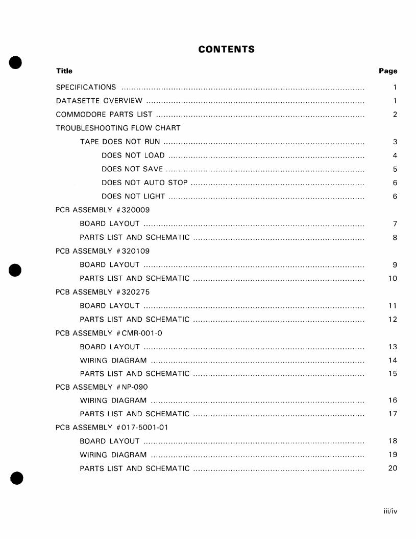
CONTENTS
Page
1
DATASETTE OVERVIEW. ... ..... ............................ ..... ...... ............. ...... ........ ............. 1
COMMODORE PARTS LIST..................... ............ ......................... ......... ................. 2
TROUBLESHOOTING FLOW CHART
TAPE DOES NOT RUN........................... .............................................. ........ 3
DOES NOT LOAD .............................. ................. ........... ..................... 4
DOES NOT SAVE .......... .............. ............... ......... ................................ 5
DOES NOT AUTO STOP ...................................................................... 6
DOES NOT LIGHT ............. ...... ....................... .......... ........................... 6
PCB ASSEMBLY # 320009
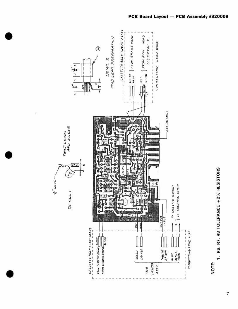
BOARD LAYOUT .......... .................... ........ ................................. .................. 7
PARTS LIST AND SCHEMATIC ...... ............ ................................. .................. 8
PCB ASSEMBLY # 3201 09
BOARD LAYOUT ......................................................................................... 9
PARTS LIST AND SCHEMATIC ..................................................................... 10
PCB ASSEMBLY # 320275
BOARD LAyOUT..... ..... ........... ...................... .............. ................................ 11
PARTS LIST AND SCHEMATIC ........... ....... ...... ............. ................... ............. 12
PCB ASSEMBLY # CMR-001-0
BOARD LAYOUT ...................................... .............................. ......... ............ 13
WIRING DIAGRAM ........... ............ ............ ...................................... ............. 14
PARTS LIST AND SCHEMATIC ...... ................................................. .............. 15
PCB ASSEMBLY # NP-090
WIRING DIAGRAM .. ..... .................... ........ ......... ..... ..................... .... ............ 16
PARTS LIST AND SCHEMATiC...... ............ .............................. ..................... 17
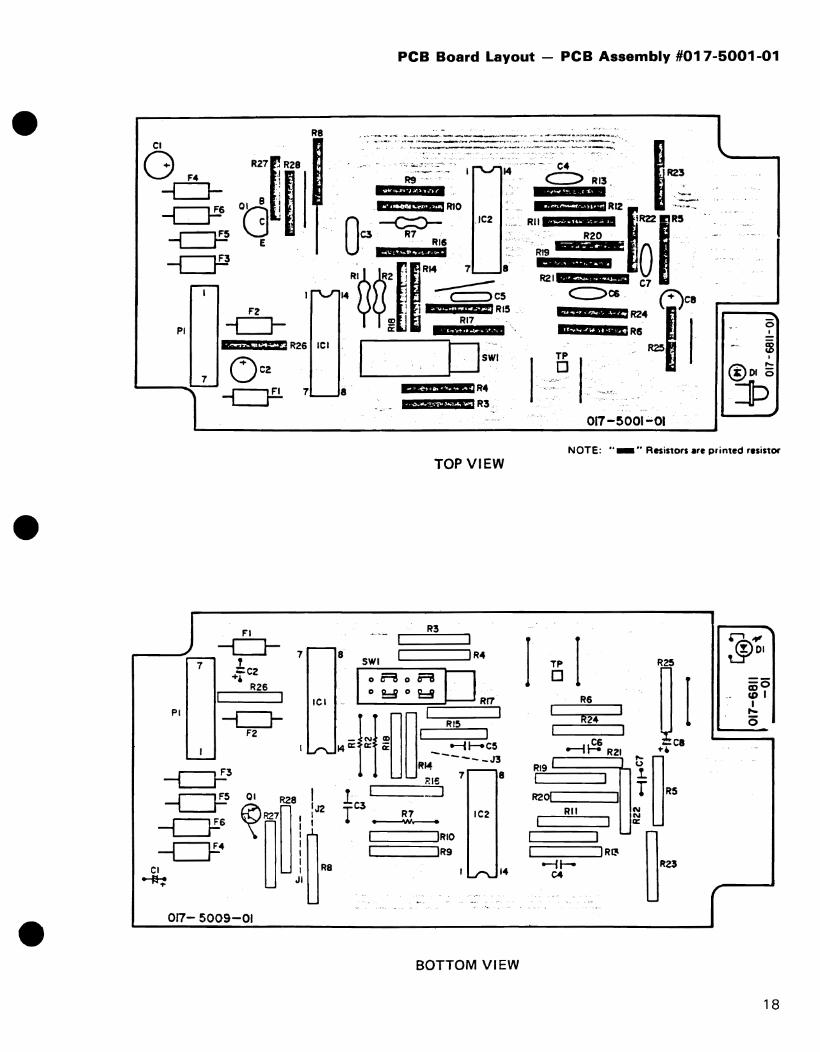
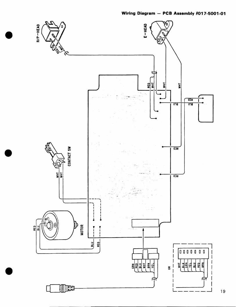
PCB ASSEMBLY #017-5001-01
BOARD LAYOUT.. ... ..... .................... ........ ..... ...... ............. .... ..... ..... ..... .... .... 18
WIRING DIAGRAM .. ..... .................... ...................... .............. ............ ........... 19
PARTS LIST AND SCHEMATIC .... ......... ..... ........ .......... .......... ..... ........... ....... 20
iii/iv

SPECIFICATIONS
SPEED
300 baud throughput, programs saved twice for internal error checking, check-summing for data files.
CONTROLS
Keys for play, record, fast-forward, rewind, and stop. Sensor for software detection of key press. Counter for tape location.
FORMAT
Commodore propriety format using pUlse-width modulation and square waves. Allows naming of programs and files, verification of programs, end of tape marker sensing.
TAPES
Uses standard audio cassette tapes. Digital tapes not required.
COMPATABILITY
C2N!1530 - VIC20, C64, PET Series Computer
1531 - PLUS 4, C 16
DATASETTE OVERVIEW
The electronics of the datasette contains read/write circuits that replace the audio-type circuits in a standard audio tape recorder.
Status/Motor Control - When the play switch is depressed, a ground potential is applied to the cassette enable line of the microprocessor. It, in turn, signals the cassette drive motor through a transistor switch located on the main computer board. The cassette is then ready for read/write operation.
Write/Record Amplifier - The computer outputs a square wave signal to the datasette. These TTL logic-level shifts are converted by the pre-amplifier and power amplifier to a proportional current output. This current output is then applied to the read/write coil of the head. Through induction, magnetic fields are produced on the tape representing the data.
Read/Playback Amplifier - The read amplifier circuit takes the reproduced transition signals from the tape and converts them back to TTL logic-level shifts. This is accomplished by an amplifier limiter which removes the amplitude variations and a switching circuit that toggles the output data between o and 5 volts. The signal is then ready for output to the computer.
1

NOTE: We are unable to stock the numerous small parts of the various mechanisms that have been used in the Commodore Datasette. Therefore, references have been made throughout this document to the vendor names we have used as our suppliers. If you would like to have parts for these mechanisms, may we suggest you contact the vendors directly.
PARTS LIST
Parts that are available from Commodore at this printing:
32004001 980040 980048
C2N/1530 I/O Harness Assembly C2N/1530 Case (2 piece) OLD style C2NJ1530 Replacement PCB Assembly # 320275
Parts that will be available from Commodore - Call for Part Number, Price, Availability.
C2NJ1530 Case (2 piece) NEW style 1531 Case (2 piece) 1531 I/O Harness Assembly
2
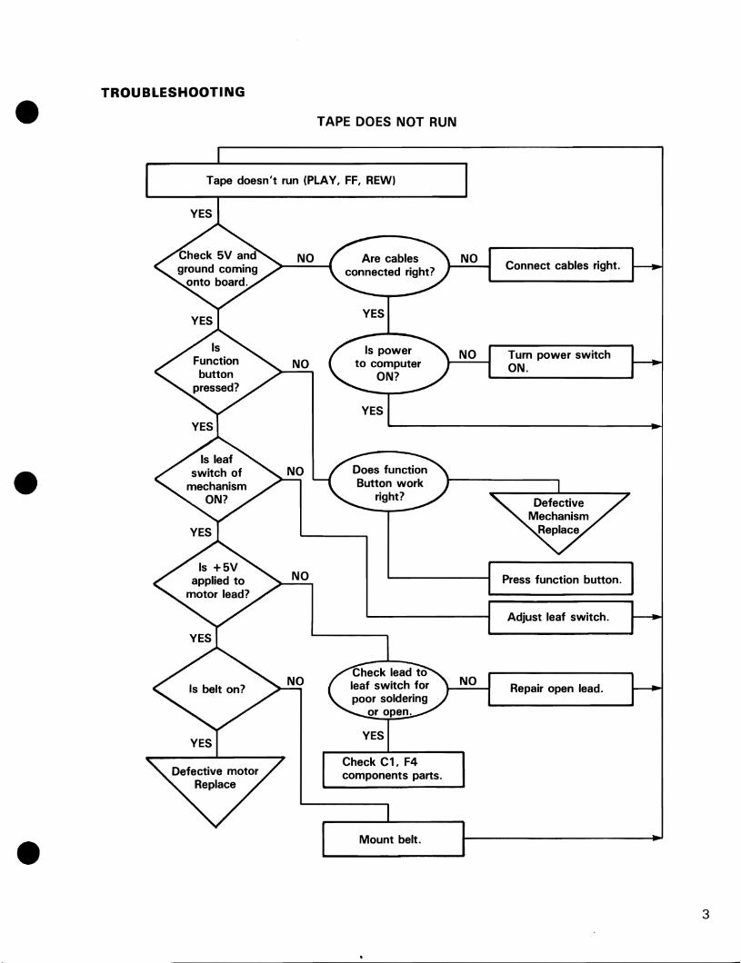
TROUBLESHOOTING
TAPE DOES NOT RUN
Tape doesn't run (PLAY, FF, REW)
Check C1, F4 components parts.
Mount belt.
Connect cables right.
Turn power switch ON.
Press function button.
Adjust leaf switch.
Repair open lead.
3

Doesn't load
NO
NO
NO
NO
NO
DOES NOT LOAD
Repair open lead.
Replace Head. Readjust Azimuth.
Set to Playback mode.
Due to the variety of Datasettes in the field, it is not possible to develop a flowchart to cover all of the component failures that are possible. From this point it is suggested that you:
1) Check for proper head alignment
2) Check for proper operation of the semi-conductor components on the PCB assembly
3) Check component parts directly related to the proper operation of the I.C.'s and transistors in the circuit.
4) Check I/O cable to computer and proper operation of the computer.
4

DOES NOT SAVE
Doesn't save
NO
NO
NO Check lead to head for soldering and open.
5

•
•
DOES NOT AUTO STOP
NO
NO
Press PLAY at tape end.
Clean pinch roller.
DOES NOT LIGHT
Check cable. computer.
Check resistor and component parts .
6
-....J
e c.A
SS
ET
TE
AS
S'\
' (N
EX
T A
SS
Y)
r--------------,
BL
AC
IC
I f~OM
CA
SS
eTT
[ FRA"E~
FK
oM
CA
SSE
TTE
S""~
"VIC
IC
FROM
CONN
ECTO
RI
A S
SY
" I
&R
E£/
II ~
....
:...
...:
~-Ra---.
OR
tlN
6-E
~
---''-
'-'-''~1
IIIg
I
-f;"L
ON
6
DE
TA
IL
I
'w/t
rTt:
c::
==
J---
vv
,
r-v
'
BR
OW
N ~
-:-......
.....:.I,
:..:N..:..
.P...:::
U:...:.T
__
__
......l
I
8tU
£
i aL
AC
",
" ~ED
~....!..........
~~
c::
::=
::J-~
I L
__
__
__
__
__
__
_
....1
CO
NN
EC
TIN
G-
LE
AD
WI~E.
NO
TE
:
To
C
tl5
5E
TT
E
SV
JIT
C.H
} TO
T
ER
MIN
AL
..
ST
RIP
A
8
1.
R6,
R7.
R8
TO
LE
RA
NC
E
± 2
% R
ES
IST
OR
S
e rWI:
sr L
E:,
l/O
J
AN
D .sOLOc~
.sE
E D~TAIL
I
e
1 ,:1 rf1
-=
.
?Z
DE
T,L
JIL
2
HE
AD
LE
AD
P
RE
PA
RA
TIO
N
CA
SS
ET
TE
AS
SY
(N
EX
T I
'ISS
Y")
,..
--
----
--
--
--
--
--
--
--,
II
JH
I T
e
BL
UE
RE
"O
WI-
UT
E
J F
RO
M
ER
AS
£ H
EA
D
} F
RO
M R
/w
HE
AD
I
.5E
E D
ET
AIL
2
__
__
__
__
__
..J
CO
NN
EC
TIN
G-
LE
AD
W
IRE
"a
n III m
o I» .. a.
I""
CII
'< o C .. "a
n m ,. • • GI :I CT
<
=I
t: W
I\
) o o o CD

PARTS LIST - PCB ASSEMBLY #320009
NOTE: DATASETTE PARTS ARE NOT AVAILABLE FROM COMMODORE - parts list is for cross reference only.
INTERGRATED CIRCUITS RESISTORS (Continued)
lel LM 358 (T.I.) Sub: R16 100K
NA 798 (Fairchild) Sub: R18 100
LM 258 (T.I.) R19 470 R20 10K
TRANSISTORS R21 3.3K R22 100
01 NPN 2SC945 Sub: 2N3904 R23 lK 02 NPN 2SC945 Sub: 2N3904 R24 10K 03 NPN 2S0468 (H) Sub: 2S0471 (NEC) R25 10K
04 NPN 2S8562 (H) Sub: 2S8564 (NEC) R36 15K
05 NPN 2SC945 Sub: 2N3904 CAPACITORS
DIODES Cl Electrolytic 47 J.tF 10V
CR1-CR4 IN4148 C2 Electrolytic 10 J.tF 10V C3 Film .1 J.tF 100V
RESISTORS - All values are in ohms-l /4 W C4 Ceramic .001 J.tF 50V 5% unless noted otherwise. C5 Ceramic .1 J.tF 16V
C6 Ceramic .001 J.tF 50V R1 220K C7 Ceramic .01 flF 50V R2 15K C9 Ceramic 100 pF 50V R3 270 Cl0 Ceramic 100 pF 50V R4 10K Cll Ceramic .001 flF 50V R6 5.6K 1/4w 2% (sub 1 %) C17 Ceramic .1 flF 16V R7 10K 1/4w 2% (sub 1 %) R8 47 1/4w 2% (sub 1%) MISC. R9 10K R10 10K SWI Slide Switch SEA-621
R11 10K R12 10K R13 2M R14 4.7K R15 1K
PLAY
I
I I
R.2.
15K
CIJ.{)()I
Cb r .001
AloTE(';
51.00 I?b
1 /0 ,.h, It. t/
/VOTE{IJ
R.7 /D I:.. 1<9101(
U1 1 REC R22 I o~ I I()() :LS 85".,
ERASE. L _ _ _ +-SV _____ ...:; tAl 1 __
R.20 10J.(
HEAD
NOTES: 1. R6, R7, RS, ±2%. 1/4 WATT. 2. THE BIAS SHOULD BE +1.7 ±O.005VAT 5VPOWER SUPPLY. 3. UNLESS OTHERWISE NOTED, 1/4 WATT CARBON FILM 5%
WITH VALUES IN OHMS. 4. UNLESS OTHERWISE NOTED, ALL CAPACITOR VALUES IN
MICRO FARADS.
Schematic Circuit Diagram - PCB Assembly #320009
+ 5"1/
I -I"'Si/ ~-----*--O----lI __ (G RIE[;;N )
CI + 47 /01"
(R£D)
8

to
e e
.9~!
J'-E
J'!>
rJt!
~)(c
~~~
rd
To C
l/SSETT~ S
W
FlU
)"" 1::'
~...: ~'--
------
----"I
• -
HA~NE.$S
±E
!'
ssr
~K,.
.... t =
-:
",,6
tIJ=
-
~'5mElTE.S'''
BI..
.... c.
.K. ~
FR
OM
{
"V'C
K =
H
AK
I>/E
SSA
S$r
IUD
=
-~I
l"rl
f
wH
ITI;
~
MD
rO
R
l S
/{IE
tD K
/,U'-'-
C.O
/{N
EC
JiN
o,
L£
,40
W
ill
E
NO
TE
S:
1.
R6,
R7,
R8
± 2
%,
1/4
W R
ES
IST
OR
2.
X
MA
RK
AR
E J
UM
PE
R W
IRE
S
3.
ALL
CO
NN
EC
TIO
NS
TO
CO
MP
ON
EN
TS
SID
E
e
~4
Srl
lEL
P "
,IR
E.
i::~' ~ FI~:::2l
9 H
EA
D
LE
Af)
W
ITH
B
l"U
< T
lIBE.
DE T
AIL
t H
EA
D
LE
AD
,C#
§E
I"C
E !3~SJ_
(N:,
<! J
1s,
s1.L
_ I
I I
F-o
f "t1~"1"-f8'H8::1--+----.--=
BL
II (I
<-
1 F
ila
M E~flSE fl
EA
0
I --
= W
Hir
£.
f
RE
O
F(?
oM
/t/k
J
HE
I"lD
~
>HjE
LPWI
"E\
WI-
lirE
.. 'S
EE
D
ET
AIL
1
L _
_ _
_ _
_ _
_ _
_ _
_ _
_ _
_I
C o
lllt
JE
C T
I IV
6p
l e-
I"l (
:) II
J IR
, e
'"a
n m
m
o ell .. a. ~
ell
'< o C .. '"a
n m ,. " " CD 3 cr <
"'II::
W
I'I
J o ~
o CD
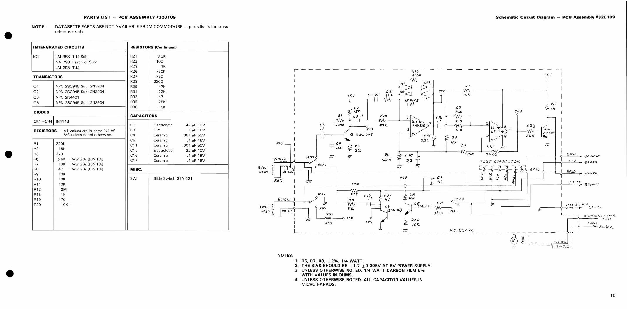
PARTS LIST - PCB ASSEMBLY #320109
NOTE: DATASETTE PARTS ARE NOT AVAILABLE FROM COMMODORE - parts list is for cross reference only.
INTERGRATED CIRCUITS RESISTORS (Continued)
IC1 LM 358 (T.I.) Sub: R21 3.3K
NA 798 (Fairchild) Sub: R22 100
LM 258 (T.I.) R23 1K R26 750K
TRANSISTORS R27 750 R28 2200
01 NPN 2SC945 Sub: 2N3904 R29 47K 02 NPN 2SC945 Sub: 2N3904 R31 22K
03 NPN 2N4401 R32 47
05 NPN 2SC945 Sub: 2N3904 R35 75K R36 15K
DIODES CAPACITORS
CR1-CR4 IN4148 C1 Electrolytic 47 J.tF 10V
RESISTORS - All Values are in ohms-1/4 W C3 Film .1 J.tF 16V 5% unless noted otherwise. C4 Ceramic .001 J.tF 50V
C5 Ceramic .1 /LF 16V R1 220K C11 Ceramic .001 /LF 50V R2 15K C15 Electrolytic 22 J.tF 10V R3 270 C16 Ceramic .1 /LF 16V R6 5.6K 1/4w 2% (sub 1 %) C17 Ceramic .1 /LF 16V R7 10K 1/4w 2% (sub 1 %)
R8 47 1/4w 2% (sub 1 %) MISC. R9 10K R10 10K SWI Slide Switch SEA-621
R11 10K R13 2M R15 1K R19 470 R20 10K
RED
R..I'N HEAD
NOTES:
Schematic Circuit Diagram - PCB Assembly #320109
1--- ---
t5V
R29
C3 't?Jc.. • I
C~
I·Dol e~
210
PLII'! R" %O()
5
CR2
l' /. F\ L{n-358
127
TP2
rp3
'2 -1:C I-e 8' L.hl-J'J8 >---<~-.J\
.3 4 +
RII
+----.-----------''v~.~-
TEST CONNECTOR,
- - -- 1
GND ORAN6£=
1"51/ GREEN >
REt.
'7sJ:.
HV -10 C' 47
--------,
_-'-~+~ : ~3 -;-i .r--~+__R.,--r-.-iu=. :----0----;.. REAO WHITE
WRlr£ eeO;VN ,
PlAt R35 C':, /~K.
I
I 1
~/X' R3Io
150 +511
TP4 R,27
Qo 1<.21 25'945 Wv--o
3300 R,"C,
/220 ~ 101<..
L k PC.80f/ RO
1. R6, R7, R8, ±2%, 1/4 WATT. 2. THE BIAS SHOULD BE + 1.7 ±O.005V AT 5V POWER SUPPLY. 3. UNLESS OTHERWISE NOTED, 1/4 WATT CARBON FILM 5%
WITH VALUES IN OHMS. 4. UNLESS OTHERWISE NOTED, ALL CAPACITOR VALUES IN
MICRO FARADS.
I C,<)S.!> 5~\II'ClI rJr-----y--{"~~ BLACK
L - - -. rtlou.'k:! CONferJL ~ ~ r<. EO
E.,N,: ~-----""'>- ~ L/)c t::..
- ,
10

PCB Board Layout - PCB Assembly #320275
·0 Ww a:-LL ::u a: W wc.. c..en ~W ::l~ -:: en a: ww I-J: «I(JO Cen zen -W ....1....1 oz co::> ~ .. >en enW
I-
G~
11
NOTE:
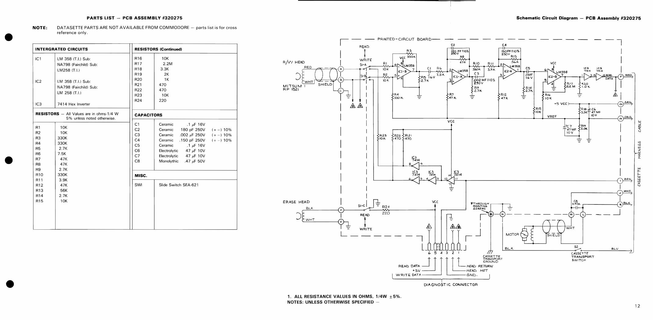
PARTS LIST - PCB ASSEMBLY #320275
DATASETTE PARTS ARE NOT AVAILABLE FROM COMMODORE - parts list is for cross reference only.
INTERGRATED CIRCUITS RESISTORS (Continued)
ICl LM 358 (T.I.) Sub: R16 10K
NA798 (Fairchild) Sub: R17 2.2M
LM258 (T.I.) R18 3.3K R19 2K
IC2 LM 358 (T.L) Sub: R20 lK
NA 798 (Fairchild) Sub: R21 470 R22 470
LM 258 (T.!.) R23 10K R24 220
IC3 7414 Hex Inverter
RESISTORS - All Values are in ohms-l/4 W CAPACITORS 5% unless noted otherwise.
Cl Ceramic .1 flF 16V R1 10K C2 Ceramic 180 pF 250V (+ -) 10% R2 10K
C3 Ceramic .002 flF 250V (+ -) 10% R3 330K
C4 Ceramic .150 pF 250V (+ -) 10% R4 330K C5 Ceramic .1 flF 16V R5 2.7K C6 Electrolytic 47 flF 10V R6 7.5K
C7 Electrolytic 47 flF 10V R7 47K C8 Monolythic .47 flF 50V R8 47K R9 2.7K Rl0 330K MISC. Rll 3.9K R12 47K SWI Slide Switch SEA-621
R13 56K R14 2.7K R15 10K
I -- -- PRIr.JTED - CI R.CUT BOARD-- ---+- -- --
R~AD C2
I t R~ 180 PF ~I07o
2~V
vce 330K RB
R/V' J H E"D I WRITE' ;'I-A RI
RED 10K CI RGo,
) 51-I R2 .1 7.5K
R5 lG.V WHT 10K 2.7K
MIISUM I R9 RP 1521 2.71-1. R4 R7 3301-1. - 47 K. -- -
&.&
vee
R23 R22. R21 10K 470 470
IC3 7"1l4
<j
IC3 10 7414 74[4
fr, It
--
ERASE HEAD vee SI-C R24
~B=L=K~ ____ ;D~ __ ~~ ~ __ ~~ ________ ~
) READ 220
WHT 1 WRITE
L __ _
I &. && I
11 JJs-J " 5 .4 3 2 I
Schematic Circuit Diagram - PCB Assembly #320275
C4
150PF±IO% 250v RI:,
RI2 47K
MOTOR
C5
.IMF 'lbV
RI4 2J'K.
RI5 10K
vee
RI" 10K
VREF=
IC3 741'l
RI7 ~'2.D 202M \.0"'-
IC.!. 7'l14
I I I I
>---.--..---~ RIB +CIO I 33K 47MF
10V
~B~L~K.~ ______________________ ~S2 c~ ___________ S_~_U ____ -4)
CASSETTE
R",D Dm J J J 1 t T HEAD ~"~.T +5V HEAD HDT
WRITE. DATA I oND. J
TRAIoJSPORT SWITC.H
1. ALL RESISTANCE VALUES IN OHMS. 1/4W ±5%. NOTES: UNLESS OTHERWISE SPECIFIED -
1 DIAGN05T Ie CONNECTOR
12

F3·
-D---c::=J!.z Gel
7 ---r==r 7
FI 7 PI --CJ-7 e2
~ F2 .....
--c=J- . --c=J-
F3 F4
I -CJ---c=:rs CI
~P2 ~ []
PCB Board Layout - PCB Assembly #CMR-001-0
lei
CMR-OOl-O
TOP VIEW
8"I~H o:H i~ lei
· · t~ 14 R9 (;31 1
-;;;-- T • w;
tR: RII .... , • te2
RI2 .,.. • RI3
• '.-cl. • C4
-ir-=
P3
8CS+ lRI~ . 1 ..
14 T c: r ... ~ C8 R25
• •
CMR-OOI-O
BOTTOM VIEW
o o J
U
@Ol ~
ct
13

0, .
~ \ 0,
f h J ~ ,I
~ Al:!9
"
~~\i r--;--~, ~r-I) Cl)l cc'\, " )
)118
Wiring Diagram - PCB Assembly #CMR-001-0
o c( w X I
W
't
Z ol=> Q:,", .... <!)Q:a>
>-z ::I:Q: 3: a>
•
"""" ...J...J a> a>
· I n18 l . n18 I
• • a::Cj
I 13A 91:10
14

NOTE:
PARTS LIST - PCB ASSEMBLY #CMR-001-0
DATASETTE PARTS ARE NOT AVAILABLE FROM COMMODORE - parts list is for cross reference only.
INTERGRATED CIRCUITS RESISTORS (Continued)
ICl IC LA6324 or NJM-2902N R19 7.5k ohm
IC2 IC M53214P or OM7414N R20 47k ohm R21 47k ohm
DIODES R22 330k ohm R23 2k ohm
01 LED RED 3<1> R24 2.7k ohm LEO Spacer R25 3.3k ohm
RESISTORS - All Values are in ohms-l 14 W CAPACITORS 5% unless noted otherwise.
C1 Aluminum 0.47p,,/25V R1 470 ohm C2 Electrolytic 47,-t/10V R2 470 ohm C3 Mylar 47,-t/10V R3 470 ohm C4 Ceramic 150p R4 220 ohm C5 Mylar 0.1/.! R5 2.7k ohm C6 Ceramic 180p R6 2.7k ohm C7 Ceramic O.OO22/.! R7 2.2M ohm C8 Electrolytic 47/.!!10V R8 lk ohm R9 10k ohm MISC.
R10 10k ohm R11 47k ohm SWI Slide Switch
R12 3.9k ohm R13 56k ohm F1 Ferrite Bead
R14 10k ohm F2-F6 Ferrite Bead QIBRHW3.5x4.5xO.8
R15 330k ohm R16 330k ohm CN1 7 Pin Connector
R17 10k ohm R18 10k ohm
I
R3 470
R £C LAMP 5
,$ 6 SWI-ol
R4 220
r-- 7 4
S- a ::3' £/H
SWI-al
,1 9 R/PH " &11 10
-1 II
I r..J.. 1 16 I '5 I !
CHECK 14 RMINALI I
,3 I TE
12n. I I· .... ' "D- I
-
R2 470
IC I 290Z N or L A6324
RI6 R20 330K 47K
SWI- ICI-4 0' RIB ICI-3 C5 12 1'+-4 R22
10K 330K -...,.. 10 ~8 .1/50 L- 14
-'" 13 V ~ 9 RI9 SWI:04 t/ll RI7 1.5K R21 471< ~t-10K
Rl5 330K
~~ .0022
R6 R24 2.7K 2.71<
@: ports utracled from thl 5190-01T (JPN MOLEXI pin ploy.
o A II Resislonce values art in n , K :.101 , M: 10' • o All Resislors art voled 01 1/4 Wall, ! 5"10. o A II Copocilonce yoluf$ or. in !IF, p= 10-'"F. o A tl Copocilors or. voled at '!JOW".
Schematic Circuit Diagram - PCB Assembly #CMR-001-0
- - SW2 PlAY S w
~:J I
+:h CI I4'1125 2 _~
CN-I RI r -.,
470 --f.ED-+-<> I I GRN 1C2-5 14 RI4 10K ~!I 4 ...... ~3 I I L..fnJ-f--o 2 I R£ 0
IC2-2 C2 "- --mJ-+--o3 I BLU a .u~~
47110 -- I I +" r- -£ITH-041WHT le2-4 1C2-3 IC 2 R25 - I I
M53214 or OM7414 3.31< ,F2 Sl8RN
f--rm+o6\ 8LK RII R9 RIO 41K
J~ '0' 10K -.l 1"0 7 , SHEl
RI2 6~7
IC2-6 IC2-1 LT~ WI.' 3.91< 2 _ .L~l !~~ 2
~V 12 '7 .1/50
LEO
RI3 561< ICI-2 I
~I~ R7 2.2M
+ C8 R5 R8 R23 l 2.7K IK 2K F47/10
:~ T.P
15

0)
e e
RIP
HEA
D E.
HEA
D
LED
0'
r<l'
>O
W
a: a
: O
CI
UO
...J
ii
o /f'l
W
l-
o /f'l
~ u <
...J
.. 0
W
HIT
E
i ID
B
LAC
K 2
20
YEL
LOW
2!
S0
RED
$,:L·.
>·~:::
,-.. ..
......
.'1. 1
1 !
'1"
I~
f. I
'.,-
, .•
• -"
•. ,....
' ,
• ...
\ ' ..•
, ...
. t...
...
...,
J
•• ~.
• I
t . {
J .~
.' ~
. ,.
..,
, ,,'..,. ~
• •
--
1-1
d ~':: .
:;'< •.....
. :>., ~ ..
~'...
. : . :' ~
, .. ': J
j ~.>~/
.""
-i' I
· .•
I
, '
. '"
I'" .'
• .'
..• '.
•
~; "r~'~ . i ':
: r·
· . ~.
l .:
': ':
.-:~ ... <,
; .'.,~~:
;:,' ~
... ,
'0 \
:!:;
.
. I
~
;; ..
.. "
.. or'
;: if
.: .. ,:~.,
. J,:~,.".I.~
:: ....
. };:.
I:
'.;.
~"
.. ,',., J);
I(~3:;
,~, ::::
\;~,
~. ~t.1
.. t •
-..
..•.
1 i'
r
~
r 'f
,
,.,
f' ~
:,' t'"
:'
t;' .
....
..
.
, I
('
'j
, ;:
:;:.':
I "',
I',
.. ....... ·
:1:
r
..... ·:1
"
.J •• ~ •
,'.
.. I ,
.',
., " ':.
,., ~
.....
t' 'I
,'" ..
,i
, ',. , '
:;-':;:
1. 1 r
·~""4~ ';
, "
':(,
..... \~
.':
:,';J
:' .~:.' :.\
...... ;.
:. ,.
,:.;./
,1.1
. ',-
;.:!'t
·· ~.
-
, I-
--J
'~"'<.' ..
. \:.
RED
G
RA
Y
BLA
CK
WH
ITE
BR
OW
N
e
MOT
OR
CONN
ECTO
R
LEAF
SW
ITCH
BLU
E
~ .. S' a:! C
i'
a:! .. I» 3 ."
n a:I ,. tI
) tI
) CD 3 CT <
=-=
2 ."
I o CD
o
NOTE:
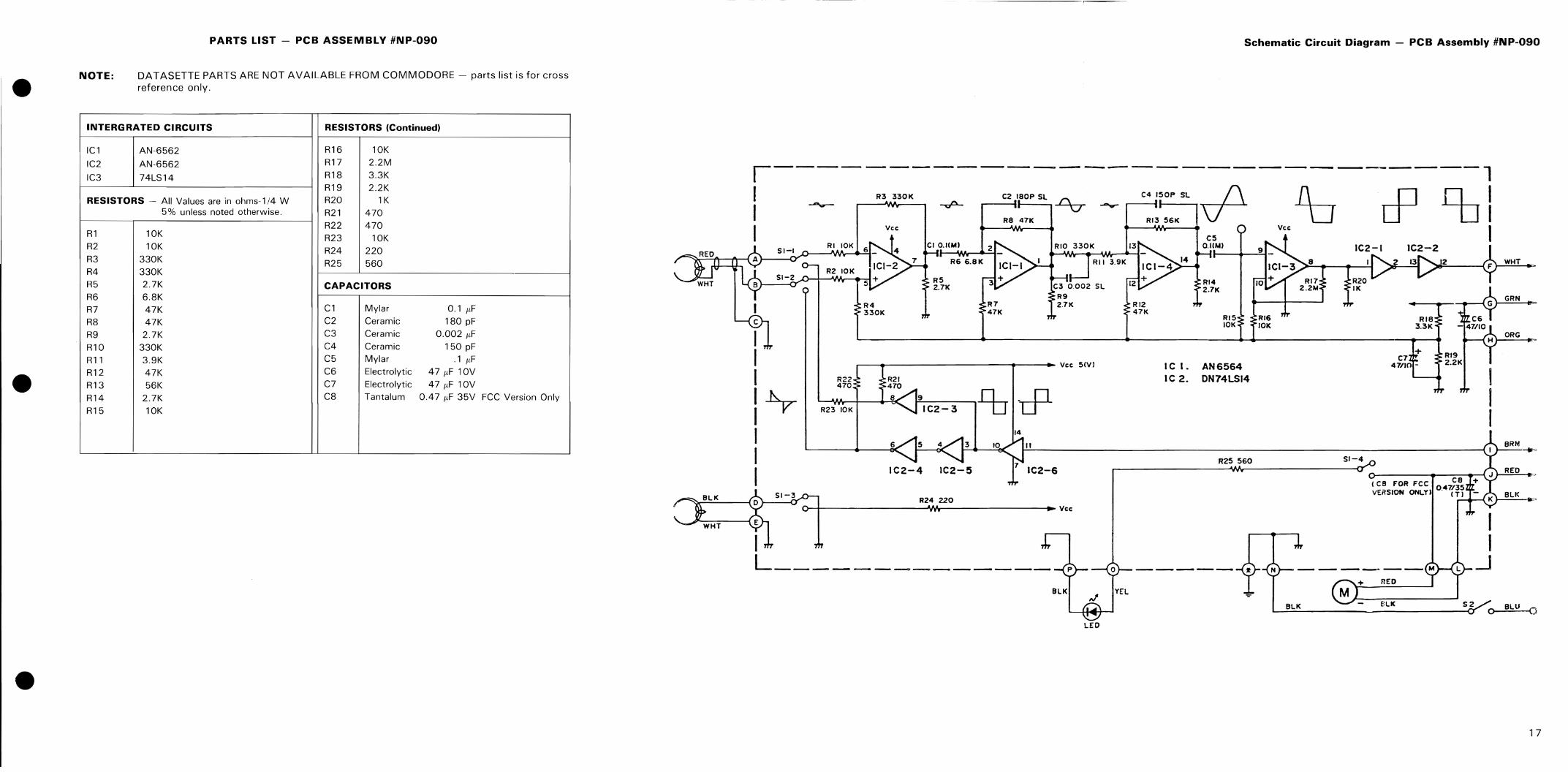
PARTS LIST - PCB ASSEMBLY #NP-090
DATASETTE PARTS ARE NOT AVAILABLE FROM COMMODORE - parts list is for cross reference only.
INTERGRATED CIRCUITS RESISTORS (Continued)
ICl AN-6562 R16 10K
IC2 AN-6562 R17 2.2M
IC3 74LS14 R18 3.3K R19 2.2K
RESISTORS - All Values are in ohms-1/4 W R20 lK 5% unless noted otherwise. R21 470
R22 470 Rl 10K R23 10K R2 10K R24 220 R3 330K R25 560 R4 330K R5 2.7K CAPACITORS R6 6.8K R7 47K C1 Mylar 0.1 r<F R8 47K C2 Ceramic 180 pF
R9 2.7K C3 Ceramic 0.002 ItF
Rl0 330K C4 Ceramic 150 pF
Rll 3.9K C5 Mylar .1 r<F
R12 47K C6 Electrolytic 47 r<F lOV
R13 56K C7 Electrolytic 47 r<F 10V
R14 2.7K C8 Tantalum 0.47 r<F 35V FCC Version Only
R15 10K
Schematic Circuit Diagram - PCB Assembly #NP-090
,------------------------------,
I --- 03330K -.p- :: '::: SL % -- C:,~':::L ifl 1b cP % I I Vee Vcr; I
I I I
51-1
51-2
l~ I I I
RI 10K
R210K
R22 470
R23 10K
R4 330K
CI O.IIM)
R5 2.7K
R66.8K
.--..-----------r---. Vee SlY)
6
F--9 -----, n . n I C2 - 3 ---0 rr--
14
II
IC2-6
J:::-:-:-:-::KT'-----1t "-1)-+--------R-'2~""'It22-0---------1.~ Vcr;
L _______ ~ _____ _ BlK YEl
RI5 10K
IC I. AN6564 I C 2. ON74LSI4
R25 560
RI6 10K
8
RI7 2.2'"
51-4
+ C7
47(10 -
C8 + (CB FOR FCC 047/35 vERSION ONLY) . (T I -
_ ____ ., ___ M
flED
WHT
GRN
ORG
BRN
REO
BlK
BlK o BLU 0
LED
17
R27~. R28
.J~ .1
zji· E
F2
PI -c::J-
7
FI
--cJ- 7 7 be! +.
R26
PI ~
F2
0[7- 5009-01
R8
8
lei
PCB Board Layout - PCB Assembly #017-5001-01
. -,'-~--....... ",,,", " ....... ~-.-. ----.-.......... ""-~ ••• ~ <' ., ..... - ... _ ...... ..,....,..,....-... - .... _, •• ,
TOP VIEW
R3
SWI
L..-____ IR4
le2
:=:====~IRIO '--__ ---lIR9
BOTTOM VIEW
0I7-5001~OI
NOTE: .. _" Resistors .re printed resistor
=(5 ~I I ,..
(5
18
o • 1&1 X I a.. ..... a:
/lJL a:: 0 )-0 ::E
----, I -, I I
I I I I
I I I I
• ! , , I I I I I I
~J Q .... a:
Wiring Diagram - PCB Assembly #017-5001-01
all
I----~
10000000 I 1 I
I I a: I I °1
1 I I I 1 I L _____ ~
19

PARTS LIST - PCB ASSEMBLY #017-5001-01
NOTE: DATASETTE PARTS ARE NOT AVAILABLE FROM COMMODORE - parts list is for cross reference only.
INTERGRATED CIRCUITS CAPACITORS
IC1 IC LA6324 C1 Aluminum 0.47fJ./25V
IC2 ICOM7414 C2 Electrolytic 47fJ./10V C3 Mylar 0.1fJ.
TRANSISTORS C4 Ceramic 150p C5 Mylar 0.1fJ.
01 2SC1815Y or GR C6 Ceramic 180p C7 Ceramic 0.0022fJ.
DIODES C8 Electrolytic 47fJ./1OV
01 LED RED 3¢
MISC. RESISTORS - All Values are in ohms-1/4 W
5% unless noted otherwise. F1-F6 Ferrite Bead 01 BRHW3.5x4.5xO.8
R1 470 ohm R2 470 ohm
SWI Slide Switch
R7 2.2M ohm CN1 7 Pin Connector
I
R3,[ 470 ~ R EC LAMP 5 .~ (
~$ 6 SWI-at
,.- 7
9- 8 E/H
- ~ 9
' &" 10 R/PH
T It
I r-1.. 1 16
I 15 I
HECK 14 C TER MIHAL I
! I
13 : 12 I I II I
LT-J
R4~[ 220 0 )
~ 5WI-al
-
? R2 t t
IC2 LA6324 --
[] RI6 R20r J 330K 4fK SWI- IC2-3 as RIB IC2-2 ~4
R22
~ C5 JQ F~~ --... 5~7 .1/50 r=-l + B
~ 9V ~
"' Ri9 W 6 ~ It SWI-a4 7.5K ~K ~~ 10K RI5 t!~Q~
~
.0022
~I~ ~
~ ~;R6 2.7K R24.[ 2.1K ~
II RI and R2 musl b. (arbon Iyp. and nol the prinl.d on •• 21 When 7414 is used lor IC I. R I and R2 volu" are 470n. tl4W. 31 When 74L514 is used lor IC I, R I and R2 values or. 680n, 114 W. 41 Prinled r"islon R3,R4 art 1/16 Wand olh.rs or. 1132W, 111.ranc. ±5%. -• A II Reslslance values art in n , K: 10' , M: 10' . • All Rcsislon or. valed 01 1/4 wall, 15"10. • A II Capacilanct values or. in)lF, P:IO·')lF. • A II CapacilorlOr. valed at 50WV. • -fS}- Resislors or. print.d RtiislOl'S.
Schematic Circuit Diagram - PCB Assembly #017-5001-01
-
RI ~ [ ~ R26 3.3K RI4 10K ?I IC 1-5 14
1"'7.:1 10 D II 4 ~l ~
ICI-2 C2 47/10
8 0 9 6 0 5 ~rJ ICI
SW2 ~ PLAY ~
SW
-
+ IZ CI J
41125
r-F5
I
CN-I -, I
I -rm-+-o: I GRN I
21 REO
F4 I
ICI-4 ICI-3 HOl4584B or R25:[ ] C0401068 or UK
HCF401068
~, . I
3!BLU
41wHT I
51 1RN '-~ --fm-i-o
~:~[~ IC2-4 : [~ r lRIO lOt<
.'2 12~ 2~1 ICI-'
M~ ~ + 14 if 13 iT 12 - - C3 2V ~ .1/50 Vl R~K IC2-1
L.;::..J
~~ R72.2M
R5 :[ 2.7K ~ R8J 2.2K ~ R23[
2K
-
R27f 1 HK R2B
~.~ f./ L.....:.,;..;..\!;,
01 25CI815
YOI' GR
~
~~ Fr CI 47/10
-
0-1-
>-
-m+ i , l'lK 71 SHELLED ..J WIRE LT
I
:J T.P
20

commodore
Issue 1, 1984 Datasette 1 TECHTOPICS (C) 1980 COMMODORE BUSINESS MACHINES INC
Model: lS30, lS31
PROBLEM: External noise interferences cause a LOAD ERROR some newer model datasettes. An engineering change has issued; however, the possibility remains that some units reached the field uncorrected. SOLUTION:
with been have
PCB Assy # CMR-00I-0
l)REMOVE the lS0pF cap at C4 and REPLACE with a Ceramic 470pF SOWV
2)ADD C9 across R17 and R18
E/H ~ ! ~
SWI-az SWI-
OJ _ RI8 'Kll(
" tt I I 110 -- ( -* - l{!L _I
R/PH
) o
5WI-1l4 \. c..~ ~' - I(
PCB ASsy #: CMR-00I-0 017-S001-01
Note - Correct Values:
PCB Assy# 017-S001-01
l)REMOVE the lS0pF cap at C4 and REPLACE with a Ceramic 470pF SOWV
2)ADD C9 across R17 and R18 Note: use pins on SWI - resistors are printed type
RI6 3301(
ICI-!
.~ - + 9 _
II
RI ' n-
PCB Assy # NP-090
l)Check C4 for 470pF cap
2)ADD C9 across Rl and R2
Vee
PCB ASsy #: NP-090
C4 Ceramic capacitor 470pF +/- 20% C9 Ceramic capacitor .0033uF +/- 20%
SO Working Volts SO Working Volts