Embed Size (px)
Citation preview

3C
GEAR HOUSING (COUNTER ROTATION)SERVICE MANUAL NUMBER 14
90-818177--3 APRIL 2001 Page 3C-1
STERNDRIVE UNITSection 3C - Gear Housing (Counter Rotation)
Table of Contents
Specifications 3C-2. . . . . . . . . . . . . . . . . . . . . . . Torque Specifications 3C-2. . . . . . . . . . . . . Shimming Specifications 3C-2. . . . . . . . . . . Lubricants/Sealers/Adhesives 3C-2. . . . . . Special Tools 3C-2. . . . . . . . . . . . . . . . . . . . . Special Tools (continued) 3C-4. . . . . . . . . .
Counter-Rotation Gear Housing Exploded Parts View 3C-6. . . . . . . . . . . . . . . .
Drive Shaft Components 3C-6. . . . . . . . . . . Propeller Shaft Components 3C-8. . . . . . .
Special Information 3C-10. . . . . . . . . . . . . . . . . . Shift Spool Assembly 3C-10. . . . . . . . . . . . . Propeller Shaft 3C-10. . . . . . . . . . . . . . . . . . . Forward Gear Bearing Bore 3C-11. . . . . . . . Bearing Carrier 3C-11. . . . . . . . . . . . . . . . . . . Thrust Collar 3C-12. . . . . . . . . . . . . . . . . . . . . Reverse Gear Bearing Adaptor 3C-12. . . . . Forward Gear Bearing Adaptor 3C-13. . . . .
Pre-Disassembly Inspection 3C-14. . . . . . . . . . Propeller 3C-14. . . . . . . . . . . . . . . . . . . . . . . . Propeller Shaft 3C-14. . . . . . . . . . . . . . . . . . .
Drive Shaft Housing/Gear Housing 3C-15. . . . Separation 3C-15. . . . . . . . . . . . . . . . . . . . . . .
Gear Housing and Component Disassembly 3C-17. . . . . . . . . . . . . . . . . . . . . . .
Water Pump Assembly 3C-17. . . . . . . . . . . . Oil Seal Carrier Assembly 3C-20. . . . . . . . . Bearing Carrier Assembly 3C-23. . . . . . . . . . Forward Gear Bearing and Adaptor 3C-27. Bearing Carrier Disassembly And Inspection 3C-35. . . . . . . . . . . . . . . . . . . . . . . Bearing Carrier Reassembly 3C-37. . . . . . . Forward Gear Bearing Adaptor Assembly 3C-39. . . . . . . . . . . . . . . . . . . . . . . Drive Shaft Assembly 3C-42. . . . . . . . . . . . .
Propeller Shaft Assembly 3C-47. . . . . . . . . . Reverse Gear Assembly 3C-52. . . . . . . . . . . Shift Spool Assembly 3C-54. . . . . . . . . . . . . Reverse Gear Bearing Adaptor Assembly 3C-56. . . . . . . . . . . . . . . . . . . . . . . Shift Shaft Assembly 3C-58. . . . . . . . . . . . . . Pinion Bearing 3C-60. . . . . . . . . . . . . . . . . . .
Gear Housing Reassembly 3C-62. . . . . . . . . . . Gear Housing Inspection 3C-62. . . . . . . . . . Pinion Bearing Installation 3C-62. . . . . . . . . Shift Shaft Assembly Installation 3C-63. . . . Reverse Gear Bearing Adaptor Assembly Installation 3C-65. . . . . . . . . . . . .
Gear Location/Backlashes Checking and Adjustment 3C-69. . . . . . . . . . . . . . . . . . . . .
Reverse Gear 3C-69. . . . . . . . . . . . . . . . . . . . Drive Shaft and Pinion Gear 3C-71. . . . . . . Drive Shaft - Bearing Preload Tool 3C-74. . Pinion Gear Location 3C-76. . . . . . . . . . . . . . Reverse Gear Backlash 3C-78. . . . . . . . . . . Forward Gear Backlash 3C-80. . . . . . . . . . . Drive Shaft - Bearing Preload Tool 3C-88. .
Propeller Shaft Assembly 3C-88. . . . . . . . . . . . . Component Reassembly 3C-88. . . . . . . . . . Installation 3C-91. . . . . . . . . . . . . . . . . . . . . . .
Drive Shaft and Pinion Gear 3C-95. . . . . . . . . . Final Installation 3C-95. . . . . . . . . . . . . . . . . .
Bearing Carrier Assembly 3C-98. . . . . . . . . . . . Final Installation 3C-98. . . . . . . . . . . . . . . . . .
Oil Seal Carrier Assembly 3C-110. . . . . . . . . . . . Installation 3C-110. . . . . . . . . . . . . . . . . . . . . . .
Water Pump Assembly 3C-111. . . . . . . . . . . . . . . Installation 3C-111. . . . . . . . . . . . . . . . . . . . . . .
Joining Drive Shaft Housing/Gear Housing 3C-114. . . . . . . . . . . . . . . . . . . . . . . . . . .

GEAR HOUSING (COUNTER ROTATION) SERVICE MANUAL NUMBER 14
Page 3C-2 90-818177--3 APRIL 2001
Specifications
Torque Specifications
Description Torque
Screws - Water Pump Body 60 lb-in. (6.8 Nm)
Nut - Pinion Gear 70 lb-in. (95 Nm)
Screw - Gear Housing to Drive ShaftHousing
28 lb-ft (38 Nm)
Nuts - Gear Housing to Drive Shaft Hous-ing
35 lb-ft (47 Nm)
Screw - Trim Tab 23 lb-ft (31 Nm)
Screws - Shift Shaft Bushing 60 lb-in. (6.8 Nm)
Retainer - Drive Shaft 100 lb-ft (136 Nm)
Retainer - Bearing Carrier 210 lb-ft (285 Nm)
Propeller Nut 55 lb-ft (75 Nm) MINIMUM
Oil Fill/Drain Plug 40 lb-in. (4.52 Nm)
Shimming SpecificationsNOTE: All bearing preload devices must be properly installed to check all gear locations andbacklashes.
Gear Description Gear Location
Pinion Gear Height .025 in. (0.64 mm)
Forward Gear Backlash .023 in. (0.58 mm)
Reverse Gear Backlash .055 in. (1.4 mm)
Lubricants/Sealers/Adhesives
Description Part Number
3m Brand Adhesive 92-86166Q1
Quicksilver 2-4 C Marine Lubricant WithTeflon
92-825407A12
Quicksilver Needle Bearing AssemblyLubricant
92-825265A1
Quicksilver Perfect Seal 92-34227-1
Permatex Ultra Blue Silicone Sealant Obtain Locally
Quicksilver Special Lubricant 101 92-13872A1
Loctite 27131 92-809820
Quicksilver High Performance Gear Lube 92-816026A1
Special Tools
Description Tool Part Number
Backlash Indicator Rod(All Gears Except 14:28)
91-53459

GEAR HOUSING (COUNTER ROTATION)SERVICE MANUAL NUMBER 14
90-818177--3 APRIL 2001 Page 3C-3
Backlash Indicator Rod(14:28 Gears)
91-78473
Bearing AdaptorInstallation Tool
91-18605 A2
Bearing Carrier RetainerWrench
91-61069T
Bearing Driver 91-816244
Bearing Preload Tool 91-14311 A2
Bearing Removal Tool 91-816245
Belleville Washer 12-54048
Dial Indicator 91-58222 A1
Dial Indicator HoldingTool
91-89897
Drive Shaft Nut Wrench 91-56775T
Drive Shaft BearingRetainer Wrench
91-43506T
Guide Plate 91-816243
Needle Bearing Driver 91-15755T
Oil Seal Driver 91-31108T
Oil Seal Driver 91-817569T
Pinion Gear ShimmingTool
91-56048T
Pinion Nut Adaptor 91-61067 A3

GEAR HOUSING (COUNTER ROTATION) SERVICE MANUAL NUMBER 14
Page 3C-4 90-818177--3 APRIL 2001
Special Tools (continued)
Description Tool Part Number
Drive Shaft Adaptor 91-61077T
Puller Bolt 91-85716
Puller Shaft 91-31229
Puller Jaws 91-46086 A1
Puller Jaws 91-816242
Slide Hammer Puller 91-34569 A1
Forward Gear InstallationTool
91-815850
Torque Wrench (InchPound)
91-66274
Universal Puller Plate 91-37241
Water Pump AlignmentPins
91-821571 A1
Universal BearingRemoval And InstallationTool
91-31229 A7
Driver Head 91-36569T
Driver Head Rod 91-37323
Nut 11-24156
Pilot Washer 91-36571T
Puller Plate 91-29310
Puller/Driver Head 91-38628T
Reverse Gear BearingTool
91-807944T
*The 91-14311A2 Bearing Preload Tool is also used on Mercury and Mariner V-6 gearcases. Check your inventory before buying.
NOTE: Water Pump Face Seal Tool is not available separately, 26-816575A2 is a kit partnumber which includes the tool and the face seal.

GEAR HOUSING (COUNTER ROTATION)SERVICE MANUAL NUMBER 14
90-818177--3 APRIL 2001 Page 3C-5
THIS PAGE IS INTENTIONALLY BLANK

GEAR HOUSING (COUNTER ROTATION) SERVICE MANUAL NUMBER 14
Page 3C-6 90-818177--3 APRIL 2001
Counter-Rotation Gear Housing Exploded Parts View
Drive Shaft Components
74242
��
�
��
��
��
��
�
a
a
b
A
D
A
A
A(ID)
C
A
B
A
E
�
�
�
��
�
�
��
�
�
�
��
��
���
�
��
�
�
��
�
�
��
�
��
��
�
C
75664
�
a��
A
��
��
�
��
C
B
F
d
c
��

GEAR HOUSING (COUNTER ROTATION)SERVICE MANUAL NUMBER 14
90-818177--3 APRIL 2001 Page 3C-7
1 - Gear Housing2 - Pin3 - Stud4 - Screw5 - Oil Fill/Drain Screw O-ring6 - Quad Seal7 - Dowel Pin8 - Roller Bearing9 - Speedometer Fitting
10 - Drive Shaft11 - Shim12 - Bearing And Cup13 - Retainer Nut14 - Gear Drive15 - Washer16 - Nut17 - Face Plate18 - Carrier19 - Oil Seal20 - Oil Seal
21 - O-ring22 - Water Pump Body23 - Gasket24 - Gasket25 - Face Seal26 - Screw (4)27 - Impeller28 - Impeller Key29 - Coupling30 - O-rings31 - Sleeve32 - Shift Shaft33 - Retaining Ring34 - Sleeve35 - Bushing Assembly36 - Oil Seal37 - O-rings38 - Screw (2)39 - Stuffer Plug
Lubricants/Sealers/Adhesives
A - Quicksilver 2-4-C Marine Lubricant with Teflon
B - 3M Brand Adhesive
C - Loctite 27131
D - Quicksilver High Performance Gear Lube
E - Quicksilver Needle Bearing Assembly Lubricant
F -Permatex Ultra Blue Silicone Sealant
Torque Specifications
a 60 lb-in. (6.8 Nm). . . . . . . . .
b 70 lb-ft (95 Nm). . . . . . . . .
c 100 lb-ft (136 Nm). . . . . . . . . .
d 40 lb-in. (4.52 Nm). . . . . . . . . .

GEAR HOUSING (COUNTER ROTATION) SERVICE MANUAL NUMBER 14
Page 3C-8 90-818177--3 APRIL 2001
Propeller Shaft Components
DF(OD)
D
E
74723
��
�
�
�
�
��
�
��
��
�
��
��
��
��
������
��
��
�
��
�
��
����
��
�
�
�
�
�
�
�
�
�
�
�
�
��
��
�
(ID)A
b
c
d
a
75691

GEAR HOUSING (COUNTER ROTATION)SERVICE MANUAL NUMBER 14
90-818177--3 APRIL 2001 Page 3C-9
1 - Gear Housing2 - Screw - Trim Plate Or Tab3 - Nut4 - Screw5 - Lockwasher6 - Anodic Plate Or Tab7 - Shift Crank8 - Shift Spool Assembly9 - Shims
10 - Bearing Adapter - Reverse Gear11 - Roller Bearing12 - Thrust Washer13 - Thrust Bearing14 - Roller Bearing15 - Reverse Gear16 - Retainer Spring - Cross Pin17 - Clutch18 - Cross Pin19 - Propeller Shaft20 - Forward Gear
21 - Shim Spacer22 - Thrust Bearing23 - Roller Bearing24 - Bearing Adapter - Forward Gear25 - Thrust Washer26 - Thrust Bearing27 - Thrust Race28 - Keepers29 - O-ring30 - Needle Bearing31 - Bearing Carrier32 - Propeller Anode And Screws33 - Seals34 - Tab Washer35 - Retaining Nut36 - Thrust Hub37 - Continuity Washer38 - Spline Washer39 - Tab Washer40 - Locknut
Lubricants/Sealers/Adhesives
A - Quicksilver 2-4-C Marine Lubricant with Teflon
B - 3M Brand Adhesive
C - Quicksilver Needle Bearing Assembly Lubricant
D - Quicksilver Perfect Seal
E - Permatex Ultra Blue Silicone Sealant
F -Quicksilver Special Lubricant 101
G - Loctite 27131
H - Quicksilver High Performance Gear Lube
Torque Specifications
a 28 lb-ft (38 Nm). . . . . . . . . .
b 35 lb-ft (47 Nm). . . . . . . . . .
c 23 lb-ft (31 Nm). . . . . . . . . .
d 210 lb-ft (285 Nm). . . . . . . . . .

GEAR HOUSING (COUNTER ROTATION) SERVICE MANUAL NUMBER 14
Page 3C-10 90-818177--3 APRIL 2001
Special Information
CAUTIONAvoid damage to sterndrive unit. Drive unit damage will occur if Later Style partsare intermixed with Earlier Style parts.
Shift Spool AssemblyThe later style shift spool assembly for the counter rotation has a larger gap than the earlierstyle. This later style shift spool, beginning with serial number 0F726586, is sold as a wholeassembly and must be used when replacing the earlier style (Prior to S/N 0F726586).
75219
74877
a
b
c
c
a - Earlier Style Shift Spool Assembly (Prior to S/N 0F726586)b - Later Style Shift Spool Assembly (S/N 0F726586 and Above)c - End Play Measurement
Propeller ShaftThe later style propeller shaft has a groove on the shaft where the clutch slides onto theshaft. The keeper slot is also moved toward the forward end of the shaft.
75223
a
b
c
a - Earlier Style Propeller Shaft (Prior To S/N 0F680000)b - Later Style Propeller Shaft (S/N 0F680000 And Above)

GEAR HOUSING (COUNTER ROTATION)SERVICE MANUAL NUMBER 14
90-818177--3 APRIL 2001 Page 3C-11
Forward Gear Bearing BoreThe later style forward gear bearing bore is smaller (3.2635 to 3.2650 in.) than the earlierstyle (3.4985 to 3.5000 in.)This slightly smaller bearing bore for the forward gear bearingadaptor is approximately 1/4 in. (6.3 mm) smaller.
3.4985 to3.5000
75241
Earlier Style Forward Gear Bore (Prior To S/N 0F680000)
75248
3.2635 to3.2650
Later Style Forward Gear Bore (S/N 0F680000 And Above)
Bearing CarrierThe later style bearing carrier is somewhat slimmer and about an 1/8 of an inch taller thanthe earlier style bearing carrier.
75231a
b
a - Earlier Style Bearing Carrier (Prior To S/N OF680000)b - Later Style Bearing Carrier (S/N OF680000 And Above)
GEAR HOUSING (COUNTER ROTATION) SERVICE MANUAL NUMBER 14
Page 3C-12 90-818177--3 APRIL 2001
Thrust CollarThe later style thrust collar is thinner than the earlier style, but still maintains the samediameter.
75220ab
a - Earlier Style Thrust Collar (Prior To S/N OF680000)b - Later Style Thrust Collar (S/N OF680000 And After)
Reverse Gear Bearing AdaptorThe later style reverse gear bearing adaptor has a smaller diameter than the earlier styleadaptor and is designed to fit into the smaller bore gear housing.
74719 74718
a b
a - Earlier Style Reverse Gear Bearing Adaptor (Prior To S/N OF680000)b - Later Style Reverse Gear Bearing Adaptor (S/N OF680000 and Above)

GEAR HOUSING (COUNTER ROTATION)SERVICE MANUAL NUMBER 14
90-818177--3 APRIL 2001 Page 3C-13
Forward Gear Bearing AdaptorThe forward gear bearing adaptor has the needle bearing pressed into the adaptor. Forfuture reference, the needle bearing inside the bearing adapter does not require a specialdriver. The needle bearing is pressed into the adaptor until the bearing is flush with the edgeof the adaptor bore.
74720 74721
7488874886
a db
c
a - Earlier Style Forward Gear Bearing Adaptor (Prior To S/N 0F680000)b - Later Style Forward Gear Bearing Adaptor (S/N 0F680000 And Above)c - Later Style Forward Gear Bearing Adaptor Needle Bearingd - Earlier Style Thrust Washer

GEAR HOUSING (COUNTER ROTATION) SERVICE MANUAL NUMBER 14
Page 3C-14 90-818177--3 APRIL 2001
Pre-Disassembly Inspection
Propeller
REMOVAL
1. If not already accomplished remove the propeller and its mounting components.
Propeller Shaft
INSPECTION
1. Inspect the propeller shaft for side to side movement, as follows:
a. Position the dial indicator on the propeller shaft.
b. Push the propeller shaft to one side and zero the dial indicator.
c. Move the propeller shaft to the opposite side while observing the dial indicator.Ashaft deflection of more than .003 in. (0.08 mm) indicates a worn propeller shaftbearing.
2. Check for a bent propeller shaft as follows:
a. Rotate the drive shaft in gear while observing the dial indicator. If the deflection ismore than .007 in. (0.178 mm), a bent propeller shaft is indicated.
22086

GEAR HOUSING (COUNTER ROTATION)SERVICE MANUAL NUMBER 14
90-818177--3 APRIL 2001 Page 3C-15
Drive Shaft Housing/Gear Housing
Separation1. Clamp the unit on the gear case anti-ventilation plate in a suitable fixture.
2. Tilt the unit at a 45 degree angle, remove the oil fill/drain plug, then remove the driveshaft housing vent screw. Allow the drive unit to drain completely.
70115
23264
a
b
a
a - Fill/Drain Screwb - Sealing Washer
70131
b
a
a - Vent Screwb - Sealing Washer

GEAR HOUSING (COUNTER ROTATION) SERVICE MANUAL NUMBER 14
Page 3C-16 90-818177--3 APRIL 2001
3. Mark the trim tab position with a piece of tape on the gear housing and remove the trimtab.
70116
a
b
a - Trim Tabb - Extension With 1/2 In. Socket
4. Remove the bolts, nuts and washers from the port and starboard sides of the unit.
5. Remove the aft screw (in the trim tab well of the gear housing).
6. Remove the nut from the forward end of the unit.
70117
b c
a
a - Nuts, Bolts and Washersb - Nutc - Screw
7. Lift the drive shaft housing straight off of the gear case and set aside.

GEAR HOUSING (COUNTER ROTATION)SERVICE MANUAL NUMBER 14
90-818177--3 APRIL 2001 Page 3C-17
Gear Housing and Component Disassembly
Water Pump Assembly
REMOVAL
1. Remove the water face seal, water tube coupling assembly and the water pump screws.
70486
b
ca
a - Water Tube Coupling Assemblyb - Water Pump Screws (4)c - Water Face Seal
2. Carefully slide the water pump body straight up off of the drive shaft. It may be necessaryto encourage the water pump body up by gently prying up on its mounting flanges witha couple of screwdrivers.
70487
bb a
a - Water Pump Bodyb - Screwdrivers

GEAR HOUSING (COUNTER ROTATION) SERVICE MANUAL NUMBER 14
Page 3C-18 90-818177--3 APRIL 2001
3. Remove the impeller, impeller key, the face plate and gaskets. Discard the gaskets.
70605
b
a
c
a - Impellerb - Impeller Keyc - Water Pump Face Plate And Gaskets (One Gasket On Each Side Of The Face
Plate)
WATER PUMP INSPECTION
1. Inspect the water tube coupling assembly for wear or damage. If necessary replace theworn or damaged components especially the two O-ring seals on the inside, one at thetop and one at the bottom.
70613
b
b
a
a - Water Tube Adapterb - O-ring Seals (2)
2. Inspect the water pump impeller for wear on the end, top and bottom of the impellerblades. Replace the impeller if this condition is found.

GEAR HOUSING (COUNTER ROTATION)SERVICE MANUAL NUMBER 14
90-818177--3 APRIL 2001 Page 3C-19
3. Inspect for proper bonding between the hub and the impeller. Replace the impeller ifimproper bonding is found.
70500
b
a
a - Impellerb - Hub
4. Inspect the impeller blades to see if they are hardened or misshapened. Replace theimpeller if the blades are in this condition.
5. Inspect the water pump face plate and the water pump interior for roughness and/orgrooves. Replace the appropriate components if necessary.
70609
ab
a - Water Pump Face Plateb - Water Pump Body
GEAR HOUSING (COUNTER ROTATION) SERVICE MANUAL NUMBER 14
Page 3C-20 90-818177--3 APRIL 2001
Oil Seal Carrier Assembly
REMOVAL
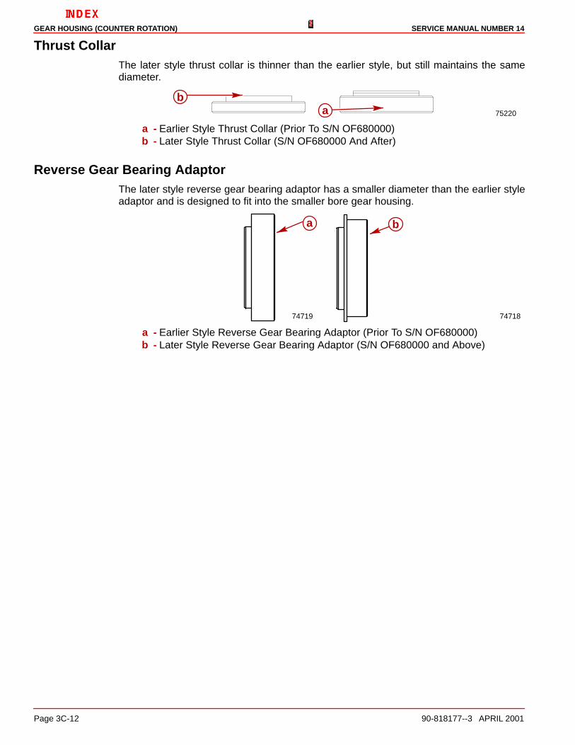
1. Remove the oil seal carrier from the gear housing. It may be necessary to gently pry upon it with two screwdrivers.
70489
b
ab
a - Oil Seal Carrierb - Screwdrivers
OIL SEAL CARRIER - INSPECTION
1. Inspect the oil seal carrier, O-ring and seals for wear and/or damage. If necessaryreplace defective parts as outlined following.
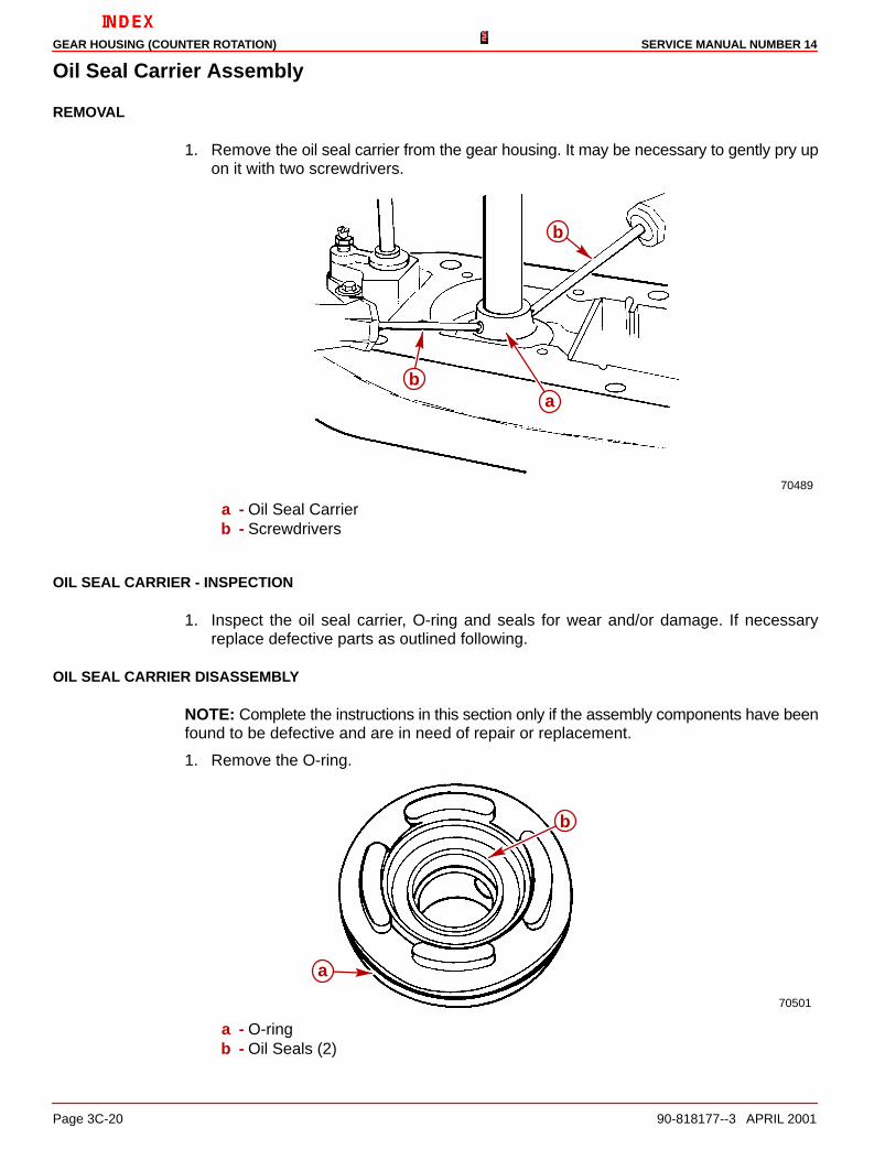
OIL SEAL CARRIER DISASSEMBLY
NOTE: Complete the instructions in this section only if the assembly components have beenfound to be defective and are in need of repair or replacement.
1. Remove the O-ring.
70501
a
b
a - O-ringb - Oil Seals (2)

GEAR HOUSING (COUNTER ROTATION)SERVICE MANUAL NUMBER 14
90-818177--3 APRIL 2001 Page 3C-21
2. Remove the oil seals.
70610
c
a
b
a - Oil Seal Carrierb - Oil Sealsc - Screwdriver
OIL SEAL CARRIER REASSEMBLY
The oil seal carrier may be a brown color (aluminum) material or a black glass filled nylonmaterial. This black glass filled seal carrier will supersede the aluminum version. The newseal carrier can be identified by looking at the base. Where the old plastic carrier had onlytwo support feet the new one will have four support feet. Also the seals in the old aluminumoil seal carrier are metal case and will require Loctite 27131 applied to the outside diameterprior to installation.
NOTE: Complete the instructions in this section only if the assembly components have beendisassembled and repaired or replaced.
71435 70501
A. Old Style B. New Style
NOTE: The earlier style oil seal carrier utilizes a large diameter and a small diameter oil seal.The later style uses the same oil seals as the drive shaft housing.
1. Apply Quicksilver Perfect Seal sparingly to the oil seal bore prior to installing the oil sealinto the oil seal carrier.
2. Assemble the small oil seal (with the lips of the oil seal facing away from the drivershoulder) onto the long end of the oil seal driver.

GEAR HOUSING (COUNTER ROTATION) SERVICE MANUAL NUMBER 14
Page 3C-22 90-818177--3 APRIL 2001
3. Press on the oil seal driver until the driver bottoms against the carrier. Do not press toohard as it could damage the oil seal carrier while driving the oil seal.
70611
a
b
c
d
a - First Oil Sealb - Oil Seal Driver (91-817569) (Use Long End)c - Oil Seal Carrierd - Press
4. Assemble the second oil seal (with the lips of the oil seal facing the driver shoulder) ontothe short end of the oil seal driver.
5. Press on the oil seal driver until the driver bottoms against the carrier. Do not press toohard as it could damage the oil seal carrier while driving the oil seal.
70612
a
b
c
d
a - Second Oil Sealb - Oil Seal Driver (91-817569) Use Short Endc - Oil Seal Carrierd - Press
GEAR HOUSING (COUNTER ROTATION)SERVICE MANUAL NUMBER 14
90-818177--3 APRIL 2001 Page 3C-23
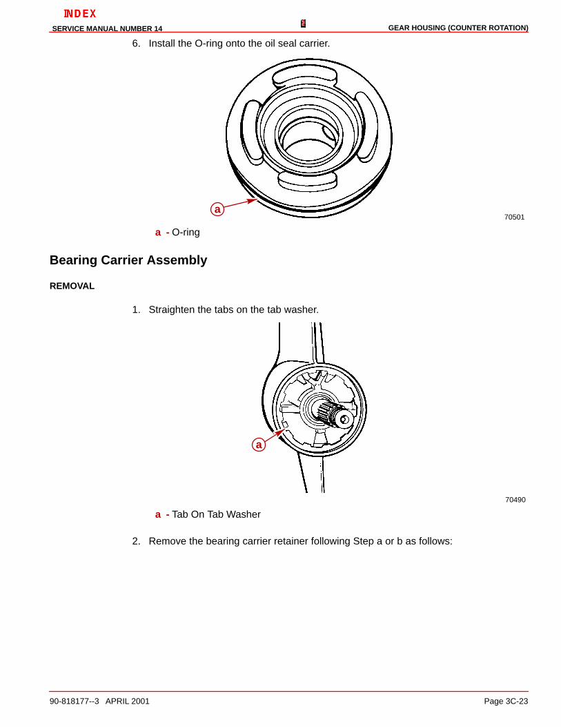
6. Install the O-ring onto the oil seal carrier.
70501a
a - O-ring
Bearing Carrier Assembly
REMOVAL
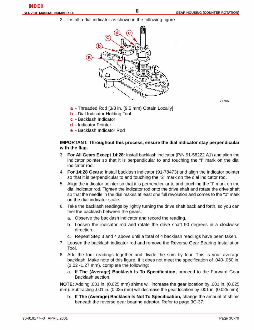
1. Straighten the tabs on the tab washer.
70490
a
a - Tab On Tab Washer
2. Remove the bearing carrier retainer following Step a or b as follows:

GEAR HOUSING (COUNTER ROTATION) SERVICE MANUAL NUMBER 14
Page 3C-24 90-818177--3 APRIL 2001
a. Remove the bearing carrier retainer using the Bearing Carrier Retainer Wrench.
70491
a
a - Bearing Carrier Retainer Wrench (91-61069)
CAUTIONDO NOT drill into the gear housing retainer threads when using the following proce-dure for removing the retainer.
b. If the retainer is corroded in place, drill 4 holes in the retainer and fracture the retainerwith a chisel. Pry the remaining segments out.
23356
a
a - Drilled Holes
3. Pull the bearing carrier from the gear housing by pulling on the outer ring of the bearingcarrier.

GEAR HOUSING (COUNTER ROTATION)SERVICE MANUAL NUMBER 14
90-818177--3 APRIL 2001 Page 3C-25
NOTE: If the bearing carrier is seized in the gear housing, it may be necessary to use heatto loosen the carrier.
50786
b
a
a - Puller Jaws (91-46086 A1)b - Puller Bolt (91-85716)

GEAR HOUSING (COUNTER ROTATION) SERVICE MANUAL NUMBER 14
Page 3C-26 90-818177--3 APRIL 2001
4. Lift the bearing carrier out of the gear housing. Locate and retain the thrust washer thatmay be stuck to the inside surface of the bearing carrier.
50826
a
50779
a
a - Thrust Washer

GEAR HOUSING (COUNTER ROTATION)SERVICE MANUAL NUMBER 14
90-818177--3 APRIL 2001 Page 3C-27
Forward Gear Bearing and Adaptor
REMOVAL
1. Remove the aft thrust bearing.
50786
a
a - Thrust Bearing
2. Remove the aft thrust collar.
50787
a
a - Thrust Collar

GEAR HOUSING (COUNTER ROTATION) SERVICE MANUAL NUMBER 14
Page 3C-28 90-818177--3 APRIL 2001
3. Lift up on the propeller shaft and push down on the forward thrust collar to remove thetwo keepers.
50778
a b
50826
b
a
a - Thrust Collarb - Keepers (2)

GEAR HOUSING (COUNTER ROTATION)SERVICE MANUAL NUMBER 14
90-818177--3 APRIL 2001 Page 3C-29
4. Remove the forward thrust collar.
50784
a
a - Thrust Collar
5. Remove the forward thrust bearing.
50783
a
a - Thrust Bearing

GEAR HOUSING (COUNTER ROTATION) SERVICE MANUAL NUMBER 14
Page 3C-30 90-818177--3 APRIL 2001
6. Form a tool using a 1/8 in. (3 mm) wire as shown in the following figure and remove theforward gear bearing adaptor.
50786
a
b
a - Wire Toolb - Forward Gear Bearing Tool
NOTE: The thrust race that must be removed in the following step has a tight fit in the gearhousing bore. Use the Forward Gear Installation Tool (91-815850) to attempt to remove thethrust race and the forward gear together. If this attempt fails, form a small hook on the endof a stiff piece of wire and try to pull the thrust race out of the gear housing. Remove O-ringprior to removal of thrust race.
7. Being careful not to damage it, remove the O-ring from inside the gear housing.
8. Remove the forward gear, thrust race and the thrust bearing (between the gear and therace).

GEAR HOUSING (COUNTER ROTATION)SERVICE MANUAL NUMBER 14
90-818177--3 APRIL 2001 Page 3C-31
9. Remove the forward gear shim.
50783
d
a
b
c
a - Forward Gear Installation Tool (91-815850)b - Thrust Racec - Forward Geard - Shim

GEAR HOUSING (COUNTER ROTATION) SERVICE MANUAL NUMBER 14
Page 3C-32 90-818177--3 APRIL 2001
COMPONENT - INSPECTION
CAUTIONEye protection must be worn when performing next procedure. Failure to do so maycause personal injury.
1. Clean the assembly and all components with a suitable solvent and dry the partsthoroughly using compressed air.
NOTE: If any of the following items are found to be defective, complete the appropriateinstruction(s).
2. Inspect the bearing carrier for signs of excessive corrosion especially in the area wherethe bearing carrier touches the gear housing. If excessive corrosion is evident, replacethe carrier.
50818
a
b
a - Bearing Carrierb - Mating Surfaces
NOTE: The bearing carrier has changed slightly. The later style bearing carrier is about 1/8of an inch taller and more streamlined than the earlier style. See “Special Information” onpage 3C-8.
a
b
a - Earlier Style Bearing Carrier (Prior To S/N OF680000)b - Later Style Bearing Carrier (S/N OF680000 And Above)

GEAR HOUSING (COUNTER ROTATION)SERVICE MANUAL NUMBER 14
90-818177--3 APRIL 2001 Page 3C-33
3. The condition of the bearing surface on the propeller shaft in the area that the needlebearing (in the bearing carrier) rides is an indication of the condition of the needlebearing in the bearing carrier. Replace the bearing if the surface of the shaft is pitted,grooved, scored, worn unevenly, discolored from overheating or has embedded metalparticles.
50698
a
a - Propeller Shaft Bearing Contact Area
4. Inspect the forward gear for pitted, chipped, broken teeth, hairline fractures andexcessive or uneven wear. Replace the forward gear and the pinion gear if any defectsare found.
5. Inspect the outer hub of the forward gear for excessive wear or damage. Replace theforward and the pinion gear if either of these conditions exist.
6. Inspect the clutch jaws of the gear for damage. Surfaces must not be chipped or roundedoff. Replace the forward and the pinion gear if any damage is found.
23355
b
a
a - Gear Teethb - Clutch Jaws
7. Inspect the thrust bearings, collars and forward gear bearing adaptor for excessive wearin the areas where the thrust bearings come into contact with them. Replace theappropriate components if they are found to be defective.

GEAR HOUSING (COUNTER ROTATION) SERVICE MANUAL NUMBER 14
Page 3C-34 90-818177--3 APRIL 2001
8. Inspect the bearing carrier retainer for cracks and/or broken or corroded threads.Replace it if any are found.
23356
a
b
a - Drilled Holes
9. Inspect the large O-ring for damage and/or deterioration. Replace it if either conditionis found.

GEAR HOUSING (COUNTER ROTATION)SERVICE MANUAL NUMBER 14
90-818177--3 APRIL 2001 Page 3C-35
Bearing Carrier Disassembly And InspectionNOTE: Complete the instructions in this section only if the assembly components have beenfound to be defective and are in need of repair or replacement.
NOTE: Inspection of the bearing surfaces on the propeller shaft where the needles of thebearing carrier needle bearing rolls, gives an indication of the condition of the needlebearing inside the bearing carrier. Replace needle bearing in the bearing carrier if the propshaft is pitted, grooved, scored, worn unevenly, discolored from overheating or hasembedded particles.
1. Perform the following Step “a” or “b” as necessary.
a. If Replacing The Needle Bearing And Seals: Remove the needle bearing andseals with the tools as shown.
23140
a
b
c
d
a - Needle Bearingb - Oil Sealsc - Driver Head (91-36569)d - Bearing Driver Rod (91-37323)

GEAR HOUSING (COUNTER ROTATION) SERVICE MANUAL NUMBER 14
Page 3C-36 90-818177--3 APRIL 2001
(1.)Discard the needle bearing and both seals.
b. If Replacing The Seal Only: Remove the oil seals with a suitable pry bar, beingcareful not to damage the bore of the bearing carrier.
23140
a
b
a - Oil Sealsb - Pry Bar
(1.)Discard both of the seals.

GEAR HOUSING (COUNTER ROTATION)SERVICE MANUAL NUMBER 14
90-818177--3 APRIL 2001 Page 3C-37
Bearing Carrier ReassemblyNOTE: Complete the instructions in this section only if the assembly components have beendisassembled and repaired or replaced.
1. Clean all of the components with a suitable solvent and dry the parts thoroughly usingcompressed air. Be careful not to spin the bearing.
2. Lightly lubricate the bore that the needle bearing is pressed into with 2-4-C MarineLubricant with Teflon. Make sure that none of the lubricant gets onto the seal bore. If itdoes, make sure that it is thoroughly cleaned off after the needle bearing is installedin the next step.
3. Press the needle bearing into the bearing carrier until the driver contacts the bearingcarrier. Ensure that the numbered side of the needle bearing faces the seal end (aft end)of the carrier.
50788
a
b
c
a - Needle Bearingb - Bearing Carrierc - Needle Bearing Driver (91-15755)
4. Thoroughly clean then apply a thin film of Loctite 27131 (92-809820) to the bore inwhich the first seal is to be pressed.
5. Assemble the first seal (with the lips of the seal facing away from the driver shoulder)onto the long end of the oil seal driver.

GEAR HOUSING (COUNTER ROTATION) SERVICE MANUAL NUMBER 14
Page 3C-38 90-818177--3 APRIL 2001
6. Press on the oil seal driver until the driver bottoms onto the aft face of the bearing carrier.
50788
a
b
c
a - Oil Sealb - Oil Seal Driver (91-31108) (Long End)c - Bearing Carrier
7. Apply a thin film of Loctite 271 to the bore in which the second seal is to be pressed.
8. Assemble the second seal (with the seal lips facing the driver shoulder) onto the shortend of the driver.

GEAR HOUSING (COUNTER ROTATION)SERVICE MANUAL NUMBER 14
90-818177--3 APRIL 2001 Page 3C-39
9. Press the oil seal with the driver until the driver contacts the bearing carrier.
50788
a
b
c
a - Driver (Short End)b - Oil Seal (Lips Toward Driver Shoulder)c - Bearing Carrier
10. Wipe up all of the excess Loctite. Do not allow any of the excess Loctite to spread toother parts of the assembly.
Forward Gear Bearing Adaptor Assembly
INSPECTION
1. Thoroughly clean the forward gear bearing adaptor with a suitable solvent and dry itthoroughly using compressed air.
NOTE: The condition of the bearing surfaces on the forward gear in the areas that thebearings of the bearing adaptor and the thrust bearing rides is an indication of the conditionof the respective bearings. Replace the bearing(s) if the surface of the gear and/or the thrustwasher is pitted, grooved, scored, worn unevenly, discolored from overheating or hasembedded metal particles.
2. Assemble the forward gear to the bearing adaptor. Inspect them for excessivemovement or roughness by rotating the gear in the adaptor. Replace the bearing in theadaptor if either of these conditions exist.
3. Inspect the adaptor for other signs of excessive wear or damage. Replace the adaptorif any are found.
NOTE: The later model forward gear bearing adapter comes with the needle bearingpressed into the adapter. For future reference, the needle bearing in side the bearing

GEAR HOUSING (COUNTER ROTATION) SERVICE MANUAL NUMBER 14
Page 3C-40 90-818177--3 APRIL 2001
adapter does not require a special driver. The needle bearing is pressed into the adapteruntil the bearing is flush with the edge of the adapter bore.
74888
ab
a - Forward Gear Bearing Adapterb - Needle Bearing
NOTE: A difference exists in the forward gear bearing adaptor. The latest style adaptor hasincorporated the earlier thrust race into the adaptor. Refer to the following illustration foridentification.
7472074721
50785
a b
c
a - Bearing Adaptor - Latest Styleb - Bearing Adaptor - Earlier Stylec - Thrust Race - No Longer Separate

GEAR HOUSING (COUNTER ROTATION)SERVICE MANUAL NUMBER 14
90-818177--3 APRIL 2001 Page 3C-41
NOTE: The latest style adapter will use a thrust washer (included in this gear set) to rideagainst the adaptor face.
74886
a
b
a - Thrust Washerb - Thrust Bearing
DISASSEMBLY
NOTE: Complete the instructions in this section only if the needle bearing in the bearingadaptor is defective and the adaptor is to be reused.
1. Remove the bearing from the adaptor using the bearing removal tool. Align the pins ofthe tool with the holes of the adaptor and apply pressure to the center of the tool so thatthe pressure is equal on both of the pins. Discard the bearing.
NOTE: The universal puller plate should rest on the press with the threaded rods on thesupports. The plate is turned in the illustration for visual clarity.
50874
a
b
cc
d
a - Forward Gear Bearing Adaptorb - Bearing Removal Tool (91-816245)c - Pinsd - Universal Puller Plate

GEAR HOUSING (COUNTER ROTATION) SERVICE MANUAL NUMBER 14
Page 3C-42 90-818177--3 APRIL 2001
REASSEMBLY
1. Lubricate the bore that the needle bearing is pressed into with Quicksilver SpecialLubricant 101.
2. If earlier style, assemble the needle bearing to the adaptor with the numbered end ofthe bearing facing the driver shoulder.
3. If earlier style, press the needle bearing into the bearing adaptor using a suitablemandrel until the bearing bottoms in the adaptor.
Drive Shaft Assembly
REMOVAL
1. Remove the drive shaft pinion nut as follows:
a. Place the drive shaft bearing retainer wrench onto the drive shaft. Do not loosen theretainer at this time.
b. Insert the pinion nut adaptor with the MR slot facing the pinion gear, into the gearhousing as shown. It may be necessary to slightly lift and rotate the drive shaft toalign the pinion gear nut into the pinion nut adapter slot.
c. Install the bearing carrier into the gear housing backwards to support the prop shaftand to keep the pinion nut adapter aligned.
d. Place the drive shaft nut wrench over the drive shaft splines and loosen, (but do notfully unscrew), the pinion nut by rotating the drive shaft counterclockwise.
70887
a
b
c
a - Drive Shaft Nut Wrench (91-56775)b - Drive Shaft Bearing Retainer Wrench (91-43506)c - Pinion Nut Adaptor (91-61067 A1)

GEAR HOUSING (COUNTER ROTATION)SERVICE MANUAL NUMBER 14
90-818177--3 APRIL 2001 Page 3C-43
e. Completely unscrew the drive shaft bearing retainer.
f. Completely unscrew the pinion nut by rotating the drive shaft (or the propeller shaft)in a counterclockwise direction.
g. Remove the bearing carrier and all tools.
h. If the drive shaft is broken, place propeller shaft nut wrench onto the propellershaft splines, hold shift shaft in reverse gear and loosen, (but do not fully unscrew),the pinion nut by rotating prop shaft counterclockwise to turn gears, thus looseningthe pinion nut.
NOTE: The propeller shaft nut wrench is included with the pinion nut adaptor kit.
70607
a
c
b
a - Pinion Nut Adaptor (91-61067 A3)b - Propeller Shaft Nut Wrench (91-61077)c - Shift Shaft (Turn Clockwise)
IMPORTANT: The pinion bearing rollers are free to fall out of the pinion bearing oncethe drive shaft is removed. Be careful not to lose the (18) rollers.

GEAR HOUSING (COUNTER ROTATION) SERVICE MANUAL NUMBER 14
Page 3C-44 90-818177--3 APRIL 2001
2. Remove the drive shaft and all components by pulling the drive shaft straight out of thegear housing as shown.
70608
a
b
a - Drive Shaftb - Drive Shaft Retainer, Bearing Cup Bearing And Shims
3. Retrieve the pinion gear by lifting up the propeller shaft to partially disengage the shaftfrom the gear enough to tilt the propeller shaft downward (away from the pinion gear).
4. Form a small hook on a stiff piece of wire and attempt to hook onto the top side of thegear and pull it out. It may be necessary to slightly move the propeller shaft fromside-to-side to dislodge the pinion gear.
50884
a
b
c
a - Propeller Shaftb - Pinion Gearc - Wire Tool

GEAR HOUSING (COUNTER ROTATION)SERVICE MANUAL NUMBER 14
90-818177--3 APRIL 2001 Page 3C-45
DRIVE SHAFT INSPECTION
1. Clean all parts with a suitable solvent and dry the parts thoroughly using compressedair, being careful not to spin the bearings.
2. The condition of the drive shaft bearing cup is an indication of the condition of thetapered roller bearing on the drive shaft. Replace the bearing and bearing cup if the cupis pitted, grooved, scored, worn unevenly, discolored from overheating or hasembedded particles.
3. Inspect the bearing surface on the drive shaft where the needles of the lower pinionbearing roll. Replace the drive shaft if it is pitted, grooved, scored, worn unevenly,discolored from overheating or has embedded particles.
4. Inspect the splines at both ends of the drive shaft for a worn or twisted condition. Replacethe drive shaft if either condition exists.
5. Inspect the gear for pitting, chipped or broken teeth, hairline fractures and excessive oruneven wear. Replace the pinion gear and the forward gear if any defects are found.
DRIVE SHAFT DISASSEMBLY
NOTE: Complete the instructions in this section only if the assembly components have beenfound to be defective and are in need of repair or replacement.
1. Press the tapered roller bearing from the drive shaft using the universal puller plate tosupport the inner race of the bearing while removing it.
70699
a
b
c
a - Universal Puller Plate (91-37241)b - Tapered Roller Bearingc - Drive Shaft

GEAR HOUSING (COUNTER ROTATION) SERVICE MANUAL NUMBER 14
Page 3C-46 90-818177--3 APRIL 2001
DRIVE SHAFT REASSEMBLY
NOTE: Complete the instructions in this section only if the assembly components have beendisassembled and repaired or replaced.
1. Assemble a new tapered roller bearing to the drive shaft with the large O.D. of thebearing facing the pinion gear end of the drive shaft.
2. Press the tapered roller bearing onto the drive shaft using the universal puller plate anda suitable mandrel, (an old tapered roller bearing inner race).
NOTE: The universal puller plate should rest on the press with the threaded rods on thesupports. The plate is turned in the illustration for visual clarity.
70700
a
b
c
a - Universal Puller Plate (91-37241)b - Tapered Poller Bearingc - Suitable Mandrel

GEAR HOUSING (COUNTER ROTATION)SERVICE MANUAL NUMBER 14
90-818177--3 APRIL 2001 Page 3C-47
Propeller Shaft Assembly
REMOVAL
CAUTIONHold onto the propeller shaft assembly in the following step to avoid personal injuryand/or dropping components when turning the gear housing over.
1. While holding onto the propeller shaft, turn the gear housing over so that the boreopening is facing down.
2. While moving the propeller shaft to the left (port) side of the gear housing, to allow theshift spool to disengage from the shift crank, lower the propeller shaft out of the gearhousing.
NOTE: The rollers of the reverse gear bearing adaptor may become dislodged whileremoving the propeller shaft assembly. If this occurs, inspect the bearing cage to see if ithas been damaged. If it has not been damaged simply snap the rollers back into position.If it has been damaged, it will be necessary to remove and replace the bearing.
50887
a
bc
a - Propeller Shaft Assemblyb - Shift Spoolc - Shift Crank

GEAR HOUSING (COUNTER ROTATION) SERVICE MANUAL NUMBER 14
Page 3C-48 90-818177--3 APRIL 2001
3. Locate and retain the thrust race and thrust bearing which could be on top of the reversegear (if not, they may be stuck to the reverse gear bearing adaptor).
50887
a
a - Thrust Bearing And Race
PROPELLER SHAFT DISASSEMBLY
IMPORTANT: When accomplishing the next step all of the parts are free to comeapart. Work closely over a work bench to ensure that the parts are not dropped ordamaged and to avoid personal injury.
1. Remove the spring around the clutch being careful not to stretch it during removal. If thespring does not coil back to its normal position once it has been removed it must bereplaced.
50885d
ab
c
a - Springb - Shift Spool Assemblyc - Reverse Gear Assemblyd - Sliding Clutch

GEAR HOUSING (COUNTER ROTATION)SERVICE MANUAL NUMBER 14
90-818177--3 APRIL 2001 Page 3C-49
2. Remove the cross pin that goes through the clutch.
50885
a
a - Cross Pin
3. Slide the spool assembly out of the propeller shaft, remove the reverse gear and slidethe clutch off of the propeller shaft.
50881
b c d
a - Cross Pinb - Clutchc - Reverse Gear Assemblyd - Spool

GEAR HOUSING (COUNTER ROTATION) SERVICE MANUAL NUMBER 14
Page 3C-50 90-818177--3 APRIL 2001
PROPELLER SHAFT INSPECTION
1. Clean all the parts with a suitable solvent and dry the parts thoroughly using compressedair. Be careful not to spin bearings.
2. Inspect the sliding clutch jaws for damage. Jaws must not be chipped or rounded off.Replace the clutch if they are.
23350
a
a - Sliding Clutch Jaws
3. Inspect the bearing surfaces on the propeller shaft where the needles of the bearingcarrier needle bearing and the needles of the reverse gear needle bearing roll. Replacethe propeller shaft if it is pitted, grooved, scored, worn unevenly, discolored formoverheating or has embedded particles.
50698
a b
c
a - Bearing Carrier Needle Bearing Contact Areab - Reverse Gear Needle Bearing Contact Areac - Splines
4. Inspect the propeller shaft splines at both ends for a broken, worn or twisted condition.Replace the propeller shaft if any of these conditions exists.
5. Inspect the surface of the propeller shaft where the bearing carrier seal lips contact theshaft. If the oil seals have made grooves, the propeller shaft must be replaced.
50698
a
a - Bearing Carrier Seal Contact Area

GEAR HOUSING (COUNTER ROTATION)SERVICE MANUAL NUMBER 14
90-818177--3 APRIL 2001 Page 3C-51
NOTE: The later style propeller shaft has a groove on the shaft where the clutch slides ontothe shaft. The keeper slot is also moved toward the forward end of the shaft.
75223
a
b
c
a - Earlier Style Propeller Shaft (Prior To S/N OF680000)b - Later Style Propeller Shaft (S/N OF680000 And Above)c - Keeper Slot and Spline Groove (S/N OF680000 And Above)
6. Inspect the propeller shaft for a bent condition. Use either one of the following methods.
a. Method 1 - V-Blocks and Dial Indicator
(1.)Position the propeller shaft bearing surfaces on V-blocks.
(2.)Adjust the height of V-blocks to level the propeller shaft.
(3.)Position the dial indicator tip just forward of the propeller shaft splines.
b. Method 2 - Lathe and Dial Indicator
(1.)Mount the propeller shaft between the centers of a lathe or other appropriatedevice.
(2.)Position the dial indicator tip just forward of the propeller shaft splines.
23355
a
b
a
a - Propeller Shaft Centersb - Dial Indicator (91-58222 A1) Check Movement Here
7. Rotate the propeller shaft and observe the dial indicator movement. If the indicator inthe dial moves more than .005 in. (.013 mm), replace the propeller shaft.

GEAR HOUSING (COUNTER ROTATION) SERVICE MANUAL NUMBER 14
Page 3C-52 90-818177--3 APRIL 2001
Reverse Gear Assembly
INSPECTION
1. Clean the reverse gear assembly with a suitable solvent and dry thoroughly withcompressed air. Be careful not to spin the bearings.
2. Inspect the gear for pitting, chipped or broken teeth, hairline fractures and excessive oruneven wear. Replace the reverse gear if any defects are found.
3. Inspect the clutch jaws of the gear for damage. The surfaces must not be chipped orrounded off. Replace the reverse gear if any of these conditions exist.
23351
b
a
a - Reverse Gear Teethb - Clutch Jaws
NOTE: The needle bearing in the reverse gear should not be removed unless damage hasbeen found. Inspect to ensure that all of the needles are present and in position. The needlesmay have become dislodged while removing the gear from the propeller shaft (and/or whileremoving the propeller shaft assembly from the gear housing). They may be snapped backinto place as long as no damage has occurred to the bearing cage.
4. Inspect the needle bearings on the inside of the reverse gear and the bearing surfaceon the propeller shaft. If either the needle bearings or the bearing surface of the propellershaft is pitted, grooved, scored, worn unevenly, discolored from overheating or hasembedded particles, replace the propeller shaft and remove and replace the needlebearing in the reverse gear.
50698
a
a - Forward Gear Needle Bearing Contact Area

GEAR HOUSING (COUNTER ROTATION)SERVICE MANUAL NUMBER 14
90-818177--3 APRIL 2001 Page 3C-53
REVERSE GEAR DISASSEMBLY
NOTE: Complete the instructions in this section only if the needle bearing in the gear hasbeen found to be defective and the reverse gear is to be reused. Bearings that have becomedislodged may be snapped back into position. If this is the only problem that exists it is notnecessary to replace the needle bearing.
1. Press the reverse gear needle bearing out using a suitable mandrel.
50778
a
a - Reverse Gear Needle Bearing
REVERSE GEAR REASSEMBLY
NOTE: Complete the instructions in this section only if the assembly components have beendisassembled and repaired or replaced.
IMPORTANT: The appearance of the forward and reverse gear is almost identical.There are two ways to distinguish between the reverse and forward gears. Thereverse gear has a shorter hub and it has a groove cut into the back of the gear justinside the thrust bearing race.
50885REVERSE FORWARD
ab
a - Shorter Hubb - Groove

GEAR HOUSING (COUNTER ROTATION) SERVICE MANUAL NUMBER 14
Page 3C-54 90-818177--3 APRIL 2001
1. Press the needle bearing into the reverse gear using bearing driver as shown.
50789
a
b
c
a - Reverse Gearb - Needle Bearingc - Bearing Driver (91-816244)
Shift Spool Assembly
INSPECTION
1. Clean the assembly with a suitable solvent and dry the parts thoroughly usingcompressed air.
2. Inspect the shift spool assembly for damage. Small nicks and burrs may be smoothed.If any parts are damaged or worn beyond repair, it will be necessary to replace thecomplete shift spool assembly. Individual parts are not available for the assembly.
3. Inspect the shift spool for wear in the area where the shift crank comes into contact.
23356
a
a - Contact Area

GEAR HOUSING (COUNTER ROTATION)SERVICE MANUAL NUMBER 14
90-818177--3 APRIL 2001 Page 3C-55
4. Ensure that the spool spins freely (it may be helpful to lightly tap the forward [castle nut]end of the shift spool shaft against a firm surface to align the internal parts).
5. Ensure that the spool has no more than .002-.010 (0.051-0.254 mm) end play.
6. To check end play:
a. Push in on the shift spool. Take measurement.
b. Pull out on the shift spool. Take measurement.
c. The difference between the two measurements is the end play.
74877
ab
c
a - Shift Shaftb - Spoolc - End Play Measurement:
NOTE: The later style shift spool assembly for the counter rotation has a larger gap thanthe earlier style. This later style shift spool, beginning with serial number OF726586, is soldas a whole assembly and must be used when replacing the earlier style (Prior to S/NOF726586).
75219
74877b
c
a
c
a - Earlier Style Shift Spool Assembly (Prior To S/N OF726586)b - Later Style Shift Spool Assembly (S/N OF726586 And Above)c - Measure End Play Here At Gap

GEAR HOUSING (COUNTER ROTATION) SERVICE MANUAL NUMBER 14
Page 3C-56 90-818177--3 APRIL 2001
Reverse Gear Bearing Adaptor Assembly
REMOVAL
IMPORTANT: Do not catch the shift crank pin with the jaws.
1. Remove the reverse gear bearing adaptor using the tools as shown in the next figure.Remove, measure and make note of the shim thickness and discard (do not reuse)the shims.
50780
d
e
f
ab c
a - Puller Shaft (91-31229)b - Nut (11-24156)c - Guide Plate (91-816243)d - Washer (91-34961)e - Puller Head (From Slide Hammer Puller Kit (91-34569 A1)f - Jaws (91-816242)
1. Thoroughly clean the reverse gear bearing adaptor with a suitable solvent and dry itthoroughly using compressed air.
NOTE: The condition of the bearing surfaces on the reverse gear, in the areas that thebearings of the bearing adaptor and the thrust bearing rides, is an indication of the conditionof the respective bearings. Replace the bearing(s) if the surface of the gear and/or the thrustwasher is pitted, grooved, scored, worn unevenly, discolored from overheating or hasembedded metal particles.
2. Assemble the reverse gear, the thrust bearing and the thrust race to the bearing adaptor.Inspect them for excessive movement or roughness by rotating the gear in the adaptor.Replace the bearing in the adaptor and/or the thrust bearing if either of these conditionsexist.
3. Inspect the adaptor for other signs of excessive wear or damage. Replace the adaptorif any are found.

GEAR HOUSING (COUNTER ROTATION)SERVICE MANUAL NUMBER 14
90-818177--3 APRIL 2001 Page 3C-57
DISASSEMBLY
NOTE: Complete the instructions in this section only if the needle bearing in the bearingadaptor is defective and the adaptor is to be reused.
1. Remove the bearing from the adaptor using a suitable mandrel.
2. Discard the bearing.
REASSEMBLY
3. Lubricate the bore that the needle bearing is to be pressed into with Quicksilver SpecialLubricant 101 (92-13872A1).
4. Position the needle bearing on the adaptor with the numbered end of the bearing facingthe driver shoulder.
5. Press the needle bearing into the bearing adaptor using a suitable mandrel until thebearing is flush with the face of the adaptor.
50790
a
b
c
a - Reverse Gear Bearing Adaptorb - Suitable Mandrelc - Bearing

GEAR HOUSING (COUNTER ROTATION) SERVICE MANUAL NUMBER 14
Page 3C-58 90-818177--3 APRIL 2001
Shift Shaft Assembly
REMOVAL
NOTE: It is possible to remove and service the shift shaft assembly (but not the shift crankinside the gear case) without removing any of the internal components of the gear housing.
1. Remove the shift shaft bushing screws and remove the shift shaft by pulling it straightout of gear housing.
70494
a a
a - Shift Shaft Bushing Screws
2. Remove the shift crank from the inside of the gear housing. Clean it with a suitablesolvent and dry it thoroughly. Inspect it for wear in the areas that contact the shift spooland inspect the splines and the diameter that goes over the locating pin for damage orexcessive wear.
23350
a
b
c d
a - Contact Areab - Shift Crankc - Splinesd - Diameter For Locating Pin

GEAR HOUSING (COUNTER ROTATION)SERVICE MANUAL NUMBER 14
90-818177--3 APRIL 2001 Page 3C-59
SHIFT SHAFT DISASSEMBLY
1. Remove the clip and slide the bushing assembly off of the straight end of the shift shaft.Remove the rubber sleeve from the shaft.
70616
a
b
c
d
e
a - Shift Shaft Bushingb - O-rings (2)c - Sleeved - Clipe - Shift Shaft
CLEANING AND INSPECTION
1. Clean all components with a suitable solvent and dry thoroughly with compressed air.
2. Inspect the shift shaft bushing for cracking, damage or excessive wear.
3. Inspect the seal inside the bushing, the sleeve and the O-rings on the outside of thebushing for damage or excessive wear.
4. Inspect the speedometer connector for damage or blockage.
If any of these conditions exist replace the appropriate components. Note that the bushingand seal are available only as an assembly.
70617 75670
c
a
b ad
c
Earlier and Later Models Showna - Shift Shaft Bushingb - Sealc - Speedometer Tube Connectord - O-ring

GEAR HOUSING (COUNTER ROTATION) SERVICE MANUAL NUMBER 14
Page 3C-60 90-818177--3 APRIL 2001
5. Inspect the shift shaft splines and seal surface for corrosion and/or excessive wear.Check fo a bent condition. Replace the shift shaft if either if these conditions are found.
70618
a
b
a - Seal Surfaceb -
SHIFT SHAFT REASSEMBLY
NOTE: Complete the instructions in this section only if the assembly components have beendisassembled and repaired or replaced.
1. Lightly lubricate the seats of the O-ring diameters on the bushing and the lip of the oilseal with Quicksilver 2-4-C Marine Lubricant with Teflon.
2. If the speedometer connector was removed and/or replaced, lightly coat the threads ofthe connector with Quicksilver Perfect Seal. Assemble the speedometer connector tothe bushing and torque the connector to 4.5 lb-in. (0.51 Nm).
3. Assemble all components as shown below.
70616
a
b
c
d
e
a - Shift Shaft Bushingb - O-rings (2)c - Sleeved - Clipe - Shift Shaft
Pinion Bearing
REMOVAL
NOTE: Inspect the bearing surface on the drive shaft where the needles of the lower pinionbearing roll. The condition of the drive shaft at this location gives an indication of the

GEAR HOUSING (COUNTER ROTATION)SERVICE MANUAL NUMBER 14
90-818177--3 APRIL 2001 Page 3C-61
condition of the needle bearing. Replace lower pinion bearing (needles and race as a set)if the drive shaft is pitted, grooved, scored, worn unevenly, discolored from overheating orhas embedded particles.
IMPORTANT: All the needle bearings (18) MUST BE in place inside bearing race whiledriving the pinion bearing from the gear housing.
IMPORTANT: Do not reuse the bearing (race or rollers) once it has been removed.
1. While holding down on the driver rod, remove and discard the pinion bearing (race androllers) using tools as shown.
70614
a
b
c
d
a - Pinion Bearingb - Bearing Driver (91-36569)c - Pilot Washer (91-36571)d - Driver Rod (91-37323)

GEAR HOUSING (COUNTER ROTATION) SERVICE MANUAL NUMBER 14
Page 3C-62 90-818177--3 APRIL 2001
Gear Housing Reassembly
Gear Housing Inspection1. Clean the gear housing thoroughly with a suitable solvent and a hard bristle brush. Dry
the gear housing thoroughly using compressed air. Ensure that all sealants, lockingagents and debris are removed.
2. Inspect the gear housing for excessive corrosion, impact or any other damage.Excessive damage and/or corrosion requires replacement of the gear housing.
3. Inspect the bearing carrier retainer threads in the gear housing for corrosion and/orstripped threads. Excessive damage to the threads requires replacement of the gearhousing.
4. Inspect bearing race/cup contact areas for evidence of bearing cup spinning. Check thatbearing cups are not loose in bearing bores. Any one bearing bore in which the race/cupis loose may require replacement of the gear housing.
5. Inspect for blockage in water inlet holes and the speedometer hole. Clean as necessary.Be careful not to enlarge the speedometer hole as this could cause erroneousspeedometer readings.
6. Make sure that the locating pins are in place in the gear housing and that thecorresponding holes in the drive shaft housing are not elongated. The drive shaft maybreak if the housings are not aligned properly due to missing locating pins or elongatedholes.
Pinion Bearing InstallationIMPORTANT: Install only a NEW pinion bearing (race and rollers). Do not reinstall apinion bearing that has been previously removed from a gear housing.
1. Lubricate the bore into which the pinion bearing is to be installed with Quicksilver HighPerformance Gear Lube.
2. Position the new pinion bearing onto the driver head, with the lettered and numberedside of the bearing positioned upward.

GEAR HOUSING (COUNTER ROTATION)SERVICE MANUAL NUMBER 14
90-818177--3 APRIL 2001 Page 3C-63
3. Insert the driver with the bearing assembly into position (by way of the propeller shaftbore) at the drive shaft bore as shown.
70615
a
b
c
de
fg
a - Drive Shaft Pinion Bearingb - Driver Head (91-38628)c - Puller Shaft (91-31229)d - Washer (12-34961)e - Nut (11-24156)f - Pilot Washer (91-36571)g - Puller Plate (91-29310)
4. Install the bearing by screwing down the nut until the bearing is fully seated against thebore shoulder.
Shift Shaft Assembly Installation1. Place the shift crank onto the locating pin in the forward section of the gear housing.
Ensure that the shift crank faces toward the left (port) side of the gear housing.
50314
b
a
a - Shift Crankb - Locating Pin

GEAR HOUSING (COUNTER ROTATION) SERVICE MANUAL NUMBER 14
Page 3C-64 90-818177--3 APRIL 2001
2. Install the shift shaft and bushing assembly into the gear housing as shown. Position thebent end of the shift shaft forward while installing it and ensure that the splined end ofthe shift shaft is engaged with the shift crank. Make sure that the O-rings are presentand positioned properly. Install the screws and tighten to hold the shift shaft into the shiftcrank.
70620
a
a - Shift Shaft Assembly
NOTE: If the pinion bearing needle bearings have fallen out, install 18 needles into needlebearing outer race. Use Quicksilver Needle Bearing Assembly Lubricant to help holdneedles in place.
23142
a
b
a - Needles (18)b - Roller Bearing Outer Race

GEAR HOUSING (COUNTER ROTATION)SERVICE MANUAL NUMBER 14
90-818177--3 APRIL 2001 Page 3C-65
Reverse Gear Bearing Adaptor Assembly InstallationNOTE: If the reverse gear, reverse gear adaptor, large thrust bearing or bearing race in thegear housing were not replaced, install the same shim(s) (or the same thickness of shim(s))that were taken out when adaptor was removed. If the reverse gear, reverse gear adaptor,large thrust bearing, bearing race or gear housing were replaced, install approximately .008in. (0.51 mm) of shims as a starting point.
NOTE: If backlash has already been checked and it has been determined that it needs tobe adjusted. Adding .001 in. (0.025 mm) shims will reduce the gear backlash byapproximately .001 in. (0.025 mm). Subtracting .001 in. (0.025 mm) shims will increasebacklash by approximately the same amount.
Example 1 (if backlash is too high)
Backlash checks:
(subtract) middleof specification:
You get:
add this quantityof shims:
.045 in.
.025 in.
.020 in.
(1.14 mm)
(0.64 mm)
(0.51 mm)
Example 2 (if backlash is too low)
Backlash checks:
middle of specification:
(subtract) You get:
subtract this quantity ofshims:
.025 in.
.009 in.
.016 in.
(0.64 mm)
(0.23 mm)
(0.41 mm)
NOTE: The later style reverse gear bearing adaptor has a smaller diameter than the earlierstyle adaptor. See “Special Information” on page 3C-8.
74719 74718
ab
a - Earlier Style Reverse Gear Bearing Adaptor (Prior To S/N OF680000)b - Later Style Reverse Gear Bearing Adaptor (S/N OF680000 And Above)

GEAR HOUSING (COUNTER ROTATION) SERVICE MANUAL NUMBER 14
Page 3C-66 90-818177--3 APRIL 2001
1. Lubricate the bore into which the reverse gear bearing adaptor is to be installed withQuicksilver Special Lubricant 101.
2. Place the shim(s) into reverse bore of gear housing.
3. Position the bearing adaptor in the gear housing.
50781
a
b
a - Bearing Adaptorb - Shims
IMPORTANT: The appearance of the forward and reverse gear is almost identical.There are two ways to distinguish between the reverse gear and forward gears. Thereverse gear has a shorter hub and it has a groove cut into the back of the gear justinside the thrust bearing race surface.
50885
a b
Reverse Forwarda - Shorter Hubb - Groove

GEAR HOUSING (COUNTER ROTATION)SERVICE MANUAL NUMBER 14
90-818177--3 APRIL 2001 Page 3C-67
4. Position the reverse gear (without the thrust race or thrust bearing) into the gear housingand into the adaptor.
50781
a
a - Reverse Gear
5. Press the bearing adaptor into the gear housing using the installation tool as follows:
IMPORTANT: Be sure that the bearing adaptor is positioned as straight as possibleto avoid cocking it in the bore while pressing it in.
a. Lubricate the threads of the installation tool with Quicksilver Special Lubricant 101.

GEAR HOUSING (COUNTER ROTATION) SERVICE MANUAL NUMBER 14
Page 3C-68 90-818177--3 APRIL 2001
b. Turn the hex-head screw of the installation tool until the bearing adaptor contactsthe gear housing shoulder. DO NOT continue to turn the tool once the screwresistance goes up noticeably.
50791
a
b
c
a - Hex-Head Screwb - Bearing Adaptor Installation Tool (91-18605 A1)c - Reverse Gear
c. Remove the installation tool and the reverse gear.

GEAR HOUSING (COUNTER ROTATION)SERVICE MANUAL NUMBER 14
90-818177--3 APRIL 2001 Page 3C-69
Gear Location/Backlashes Checking and Adjustment
Reverse Gear
INSTALLATION (FOR CHECKING BACKLASH ONLY)
1. Lubricate the large reverse gear thrust bearing with Quicksilver High Performance GearLube. First position the thrust race and then the bearing into the gear housing and ontothe reverse gear bearing adaptor as shown below.
50882
a
b
c
a - Thrust Bearingb - Thrust Racec - Reverse Gear Bearing Adaptor
IMPORTANT: The appearance of the forward and reverse gear is almost identical.There are two ways to distinguish between the reverse and forward gears. Thereverse gear has a shorter hub and a groove cut into the back of the gear just insidethe thrust bearing race surface.
50885
a
b
Reverse Forwarda - Shorter Hubb - Groove

GEAR HOUSING (COUNTER ROTATION) SERVICE MANUAL NUMBER 14
Page 3C-70 90-818177--3 APRIL 2001
2. Assemble the reverse gear into the gear housing and into the reverse gear bearingadaptor.
50884
a
b
c
d
a - Reverse Gearb - Thrust Bearingc - Thrust Race (Under Bearing)d - Reverse Gear Bearing Adaptor

GEAR HOUSING (COUNTER ROTATION)SERVICE MANUAL NUMBER 14
90-818177--3 APRIL 2001 Page 3C-71
Drive Shaft and Pinion Gear
INSTALLATION (FOR CHECKING GEAR LOCATION AND BACKLASHES ONLY)
NOTE: If the original shims were not retained or if pinion gear, drive shaft, drive shaft taperedroller bearing and cup or gear housing were replaced start off by installing .038 in. (0.96 mm)shim(s).
NOTE: If the original shims were retained (or measurement known) and none of the abovelisted parts were replaced, reinstall the original shims (or an amount of shims equal to theoriginal shims).
1. Place the shim(s) into the drive shaft housing bore at the location shown.
70620
a
a - Shim(s)
NOTE: For ease of installation, glue the washer to the tool using 3M Adhesive or equivalent.
2. Assemble the pinion gear nut into the MR slot of the pinion nut adaptor. A small dab ofheavy grease in the slot of the pinion nut adaptor will help hold the nut in the adaptorwhile installing the drive shaft assembly.
3. Place the pinion gear (with the washer glued to it) into the gear housing.
4. Insert the pinion nut adaptor (with the nut) into the gear housing.
5. Insert the drive shaft into the gear housing drive shaft bore. It may be necessary to rotatethe drive shaft to engage the drive shaft splines into the pinion gear splines.

GEAR HOUSING (COUNTER ROTATION) SERVICE MANUAL NUMBER 14
Page 3C-72 90-818177--3 APRIL 2001
6. Start the pinion nut onto the drive shaft threads by rotating the drive shaft until the nutis snug.
70891
a
b
c
a - Pinion Gear (With The Washer Glued To The Tool)b - Pinion Nut Adapter (91-61067 A3)c - Drive Shaft
7. Install the drive shaft tapered roller bearing cup then the retainer nut.
70890
a b
a - Tapered Roller Bearing Cupb - Drive Shaft Retainer

GEAR HOUSING (COUNTER ROTATION)SERVICE MANUAL NUMBER 14
90-818177--3 APRIL 2001 Page 3C-73
8. Torque the retainer to 100 lb-ft (130 Nm).
70711
a
a - Drive Shaft Bearing Retainer Wrench (91-43506)
9. Install the bearing carrier into the gear housing backwards to hold the propeller shaft andthe pinion nut adapter in position.
10. Torque the pinion nut by turning the drive shaft using the drive shaft nut wrench andtorque wrench with the appropriate socket to 70 lb-ft (94 Nm).
70892a
b
c
a - Pinion Nut Adaptor (91-61067 A3)b - Drive Shaft Nut Wrench (91-56775)c - Bearing Carrier (Installed Backwards)
11. Remove the bearing carrier, pinion nut adapter and drive shaft nut wrench.

GEAR HOUSING (COUNTER ROTATION) SERVICE MANUAL NUMBER 14
Page 3C-74 90-818177--3 APRIL 2001
Drive Shaft - Bearing Preload Tool
INSTALLATION
NOTE: Ensure that the top nut and the bottom nut of the bearing preload tool are screwedas close together as possible prior to proceeding with the following step.
1. Install the components from the Bearing Preload Tool Kit (91-14311A2), over the driveshaft in the order shown.
73885
a
b
c
e
f
g
d
d
a - Top Nut With Treaded Pipeb - Nutc - Springd - Thrust Washere - Thrust Bearingf - Thrust Washerg - Water Pump Face Plate (From Your Gear Housing)

GEAR HOUSING (COUNTER ROTATION)SERVICE MANUAL NUMBER 14
90-818177--3 APRIL 2001 Page 3C-75
2. Pull up on the drive shaft and tighten the two (2) allen screws in the top nut of the bearingpreload tool.
70716
a
a
a - Allen Screws
3. Screw the bottom nut of the bearing preload tool down until it is one inch further downthe threaded rod than it was previously.
70893
a
a - Bottom Nut (Screwed Down Approximately 1 in. (25 mm) Further Than It WasPreviously)
4. Rotate the drive shaft at least three full turns in a clockwise direction to seat the needlebearing.

GEAR HOUSING (COUNTER ROTATION) SERVICE MANUAL NUMBER 14
Page 3C-76 90-818177--3 APRIL 2001
Pinion Gear Location
CHECKING
Pinion Gear Location Specification: .025 in. (0.64 mm)
1. Place the pinion gear shimming tool into the gear housing.
NOTE: Take the following measurements at 3 locations, rotating the drive shaft 120 degreesbetween each reading (always rotate the drive shaft in a clockwise direction).
2. Insert the thickest feeler gauge that fits snugly between one tooth of the pinion gear andhigh point of the shimming tool.
26410
a
b
a - Pinion Gear Shimming Tool (91-56048)b - .025 in. (0.64 mm) Feeler Gauge
3. Rotate the drive shaft 120 degrees in a clockwise direction and take another reading.
4. Repeat this process until 3 readings have been taken.
5. Add the three readings together and divide the sum by 3 to get the average pinion gearheight.
a. If the (average) pinion gear location does not meet the specification of .025 in. (0.64mm) proceed with the adjustment instructions .
b. If the (average) pinion gear location meets specification, proceed to the ReverseGear Backlash section.
ADJUSTING
NOTE: Adding .001 in. (.025 mm) shims will increase the gear location by .001 in. (.025mm). Subtracting .001 in. (.025 mm) will decrease the gear location by .001 in. (.025 mm).
1. Loosen the preload tool.
2. Remove the drive shaft retainer and the drive shaft tapered roller bearing cup. (The cupcan be removed by wiggling the drive shaft back and forth or by turning gear housingover and shaking it.) Add or subtract shims beneath the cup to obtain the proper averagepinion gear height.

GEAR HOUSING (COUNTER ROTATION)SERVICE MANUAL NUMBER 14
90-818177--3 APRIL 2001 Page 3C-77
3. Install the drive shaft tapered roller bearing cup then install the retainer.
70890
a
b
a - Tapered Roller Bearing Cupb - Drive Shaft Retainer
4. Torque the retainer to 100 lb-ft (130 Nm).
70711
a
a - Drive Shaft Bearing Retainer Wrench (91-43506)
5. Reinstall the drive shaft bearing preload tool.
6. Recheck the pinion gear height.

GEAR HOUSING (COUNTER ROTATION) SERVICE MANUAL NUMBER 14
Page 3C-78 90-818177--3 APRIL 2001
Reverse Gear Backlash
CHECKING
Reverse Gear Backlash Specification: .040-.050 in. (1.02-1.27 mm)
NOTE: The reverse gear bearing adaptor installation tool is used to apply a light preloadto the reverse gear in the following steps.
1. Install the reverse gear bearing adaptor installation tool into the gear housing to hold thereverse gear against the thrust bearing as follows:
a. Assemble the reverse gear bearing adaptor installation tool into the gear housingand tighten it by hand until a slight resistance is felt.
b. Torque the adaptor’s driver bolt to 45 lb-in. (5 Nm).
70973
d
a
b
c
b - Torque Wrench (91-66274)c - Driver Boltd - Bearing Adaptor Installation Tool (91-18605A1)e - Reverse Gear
GEAR HOUSING (COUNTER ROTATION)SERVICE MANUAL NUMBER 14
90-818177--3 APRIL 2001 Page 3C-79
2. Install a dial indicator as shown in the following figure.
77706
edc
b
a
a - Threaded Rod [3/8 in. (9.5 mm) Obtain Locally]b - Dial Indicator Holding Toolc - Backlash Indicatord - Indicator Pointere - Backlash Indicator Rod
IMPORTANT: Throughout this process, ensure the dial indicator stay perpendicularwith the flag.
3. For All Gears Except 14:28: Install backlash indicator (P/N 91-58222 A1) and align theindicator pointer so that it is perpendicular to and touching the “I” mark on the dialindicator rod.
4. For 14:28 Gears: Install backlash indicator (91-78473) and align the indicator pointerso that it is perpendicular to and touching the “2” mark on the dial indicator rod.
5. Align the indicator pointer so that it is perpendicular to and touching the “I” mark on thedial indicator rod. Tighten the indicator rod onto the drive shaft and rotate the drive shaftso that the needle in the dial makes at least one full revolution and comes to the “0” markon the dial indicator scale.
6. Take the backlash readings by lightly turning the drive shaft back and forth, so you canfeel the backlash between the gears.a. Observe the backlash indicator and record the reading.b. Loosen the indicator rod and rotate the drive shaft 90 degrees in a clockwise
direction.c. Repeat Step 3 and 4 above until a total of 4 backlash readings have been taken.
7. Loosen the backlash indicator rod and remove the Reverse Gear Bearing InstallationTool.
8. Add the four readings together and divide the sum by four. This is your averagebacklash. Make note of this figure. If it does not meet the specification of .040-.050 in.(1.02 -1.27 mm), complete the following:a. If The (Average) Backlash Is To Specification, proceed to the Forward Gear
Backlash section.
NOTE: Adding .001 in. (0.025 mm) shims will increase the gear location by .001 in. (0.025mm). Subtracting .001 in. (0.025 mm) will decrease the gear location by .001 in. (0.025 mm).
b. If The (Average) Backlash Is Not To Specification, change the amount of shimsbeneath the reverse gear bearing adaptor. Refer to page 3C-37.

GEAR HOUSING (COUNTER ROTATION) SERVICE MANUAL NUMBER 14
Page 3C-80 90-818177--3 APRIL 2001
Forward Gear Backlash1. Install the appropriate spacer shim into the gear housing.
50882
a
a - Shim
2. Insert propshaft into housing with one thrust collar on shaft and resting on splined area.
50889
a
b
a - Splined Areab - Thrust Collar

GEAR HOUSING (COUNTER ROTATION)SERVICE MANUAL NUMBER 14
90-818177--3 APRIL 2001 Page 3C-81
3. If equipped, place the thrust race or washer on top of the thrust bearing with the steppedside up as shown in the following figure.
50785
a
a - Thrust Race
NOTE: The thrust race has been replaced with a thrust washer on S/N OF680000 andabove models.
74886
a
b
a - Thrust Washerb - Thrust Bearing

GEAR HOUSING (COUNTER ROTATION) SERVICE MANUAL NUMBER 14
Page 3C-82 90-818177--3 APRIL 2001
4. Assemble the forward gear installation tool to the forward gear. Then place it (with theforward gear, thrust bearing and thrust race, if applicable) down over the propeller shaft.Ensure that the thrust race seats evenly onto the shim. Tap the thrust race down lightlywith a soft tool; do not damage the thrust race surface.
50889
a
b
c
d
a - Forward Gear Installation Tool (91-815850)b - Forward Gearc - Spacer Shimd - Thrust Race
5. Install the forward gear bearing adaptor using a hook tool (which was fashioned whenthe adaptor was removed) as shown. Ensure that the adaptor seats evenly against thethrust race.
50889
a
b
c
d
a - Hook Toolb - Forward Gear Installation Tool (91-815850)c - Forward Gear Bearing Adaptord - Thrust Race

GEAR HOUSING (COUNTER ROTATION)SERVICE MANUAL NUMBER 14
90-818177--3 APRIL 2001 Page 3C-83
6. Remove the hook tool and, while holding down on the forward gear, remove the forwardgear installation tool.
50889
a
b
c
a - Forward Gear Installation Tool (91-815850)b - Forward Gear Bearing Adaptorc - Forward Gear
7. Lower the bearing carrier down over the propeller shaft until it is fully seated.
50888
a
b
a - Propeller Shaftb - Bearing Carrier

GEAR HOUSING (COUNTER ROTATION) SERVICE MANUAL NUMBER 14
Page 3C-84 90-818177--3 APRIL 2001
8. Align the bearing carrier “V” shaped notch with the alignment hole in the gear housingand then install the tab washer with the external tab inserted into the hole in the gearhousing.
50779
c
a
b
a - Gear Housing Tab Washer Alignment Holeb - “v” Shaped Notch In Bearing Carrierc - Alignment Tab Of Tab Washer
9. Ensure that the “V” shaped tab aligns with the “V” notch in bearing carrier.
70714
a
b
a - Tab Washerb - “V”-Tab

GEAR HOUSING (COUNTER ROTATION)SERVICE MANUAL NUMBER 14
90-818177--3 APRIL 2001 Page 3C-85
10. Generously lubricate the bearing carrier retainer threads with Quicksilver SpecialLubricant 101. Start the retainer into the gear housing threads and screw it down fullyby hand.
50881
a
a - Bearing Carrier Retainer
11. Torque the bearing carrier retainer to 210 lb-ft (285 Nm).
23355
a
a - Bearing Carrier Retainer Wrench (91-61069)
12. Apply backward pressure to propeller shaft as follows:
a. Install the pinion nut adaptor, washer and propeller nut as shown in the figure below.

GEAR HOUSING (COUNTER ROTATION) SERVICE MANUAL NUMBER 14
Page 3C-86 90-818177--3 APRIL 2001
b. Using a flat tip screwdriver placed through the access hole of the pinion nut adaptorto prevent the propeller shaft from rotating, torque the propeller nut to 45 lb-in. (5Nm). Rotate drive shaft three full turns clockwise and retorque the nut to 45 lb-in. (5Nm).
50880
a bc
d
a - Torque Wrench (91-66274)b - Propeller Nutc - Washer (91-54048)d - Pinion Nut Adaptor (91-61067A3)
NOTE: If the bearing preload tool has not already been set up, install it at this time.
13. Install a dial indicator as shown in the following figure.
77706
edc
b
a
a - Threaded Rod [3/8 in. (9.5 mm) Obtain Locally]b - Dial Indicator Holding Toolc - Backlash Indicatord - Indicator Pointere - Backlash Indicator Rod

GEAR HOUSING (COUNTER ROTATION)SERVICE MANUAL NUMBER 14
90-818177--3 APRIL 2001 Page 3C-87
14. Align the backlash indicator pointer so that it is perpendicular to and touching the “I” markon the dial indicator rod. Tighten the indicator rod onto the drive shaft and rotate the driveshaft so that the needle in the dial makes at least one full revolution and comes to “0”on the dial indicator scale.
15. Take the backlash readings by lightly turning the drive shaft back and forth, so you canfeel the backlash between the gears.
a. Observe the backlash indicator and record the reading.
b. Loosen the indicator rod and rotate the drive shaft 90 degrees in a clockwisedirection.
c. Repeat step “a” and “b” above until a total of 4 backlash readings have been taken.
d. Add the four readings together and divide the sum by four. This is your averagebacklash. Make note of this figure. If it does not meet specifications of .017-.028 in.(0.43-0.71 mm), it will be adjusted at a later step.
16. Loosen the backlash indicator rod and remove the dial indicator and its supportingtooling.
17. Remove the propeller nut, washer and the pinion nut adaptor.
a. If The Backlash Is To Specification, skip the next step (17b) and go on to step 18following.
NOTE: Installing a .002 in. (.051 mm) thinner spacer shim will decrease the gear backlashby .002 in. (.051 mm). Installing a .002 in. (.051 mm) thicker shim will increase the gearbacklash by .002 in. (.051 mm).
b. If The Backlash Is Not To Specification, complete the following instructions toinstall a different size spacer shim under the forward gear thrust race.
(1.)Remove the bearing carrier retainer, tab washer and the bearing carrier.
(2.)Using the hook tool, remove the forward gear bearing adaptor.
(3.) Insert the forward gear installation tool into the forward gear and remove theforward gear, thrust bearing and thrust race.
(4.)Remove the spacer shim.
18. Remove the items as outlined following:
a. Remove the bearing carrier retainer, tab washer and the bearing carrier.
b. Using the hook tool remove the forward gear bearing adaptor.
c. Insert the forward gear installation tool into the forward gear and remove the forwardgear, thrust bearing and thrust race.
d. Remove the spacer shim.
e. Remove drive shaft preload tool.
f. Remove drive shaft assembly.
g. Remove the reverse gear.

GEAR HOUSING (COUNTER ROTATION) SERVICE MANUAL NUMBER 14
Page 3C-88 90-818177--3 APRIL 2001
Drive Shaft - Bearing Preload Tool
REMOVAL
CAUTIONBefore loosening the top nut allen screws of the bearing preload tool, screw the bot-tom nut up as close as possible to the top nut.
1. Screw the bottom nut of the bearing preload tool until it is as close as possible to top nut.
2. Loosen the allen screws in the top nut.
3. Remove all components including the water pump face plate.
70716
a
b
c
a - Top Nut (With Allen Screws)b - Bottom Nutc - Water Pump Face Plate
Propeller Shaft Assembly
Component ReassemblyIMPORTANT: The appearance of the forward and reverse gear is almost identical.There are two ways to distinguish between the reverse gear and forward gears. The

GEAR HOUSING (COUNTER ROTATION)SERVICE MANUAL NUMBER 14
90-818177--3 APRIL 2001 Page 3C-89
reverse gear has a shorter hub and it has a groove cut into the back of the gear justinside the thrust bearing race surface.
50885
b
a
Reverse Forwarda - Shorter Hubb - Groove
1. Assemble the sliding clutch on the propeller shaft, being sure to align cross pin holesin the clutch with the slot in the propeller shaft. Make sure that the sliding clutch is placedon the propeller shaft with the grooved end of the clutch facing the propeller end of theshaft.
2. Assemble the reverse gear onto the propeller shaft.
3. Assemble the shift spool assembly to the propeller shaft being sure to align the crosspin hole of the shift spool shaft with the clutch slot.
50881
d
c
ab
a - Propeller Shaftb - Sliding Clutchc - Reverse Geard - Shift Spool Assembly

GEAR HOUSING (COUNTER ROTATION) SERVICE MANUAL NUMBER 14
Page 3C-90 90-818177--3 APRIL 2001
4. Assemble the cross pin through the sliding clutch, propeller shaft and shift spool shafthole.
50885
d
e
c
ab
a - Propeller Shaftb - Sliding Clutchc - Cross Pind - Reverse Geare - Shift Spool Assembly
5. Assemble the cross pin retaining spring over the propeller shaft and wind it around theclutch over the cross pin hole. Be careful not to distort the spring while assembling it.
IMPORTANT: Make sure that the spring is wound on so that it does not cross over onitself and that it lies flat against the clutch once it is assembled. If it does not lie flatagainst the clutch a new spring must be installed.
50885
ab
c
a - Sliding Clutchb - Propeller Shaftc - Cross Pin Retaining Spring

GEAR HOUSING (COUNTER ROTATION)SERVICE MANUAL NUMBER 14
90-818177--3 APRIL 2001 Page 3C-91
Installation1. Lubricate the large thrust bearing with Quicksilver High Performance Gear Lube.
Position the thrust race and then the bearing into the gear housing onto the reverse gearbearing adaptor as shown following.
50882
a
b
c
a - Thrust Raceb - Thrust Bearingc - Reverse Gear Bearing Adaptor
2. Rotate the shift crank toward the aft end of the gear housing until it touches against thebearing adaptor. Hold it in this position.
50885b
a
a - Shift Crankb - Bearing Adaptor
IMPORTANT: Be careful when inserting the propeller shaft assembly into the gearhousing as the needle bearings in the reverse gear bearing adaptor can becomedislodged when installing it. If it is suspected that a needle has become dislodged,remove the propeller shaft assembly. Inspect the needle bearing cages for damage.If the cages have not been damaged and a needle bearing is positioned wrong, it canbe snapped back into place.

GEAR HOUSING (COUNTER ROTATION) SERVICE MANUAL NUMBER 14
Page 3C-92 90-818177--3 APRIL 2001
3. To allow for the engagement of the shift spool with the shift crank, tilt the propeller endof the propeller shaft assembly to the left (port) side of gear housing and begin to lowerit into the gear housing.
50888
a
b
c
a - Shift Actuating Spoolb - Shift Crankc - Propeller Shaft Assembly
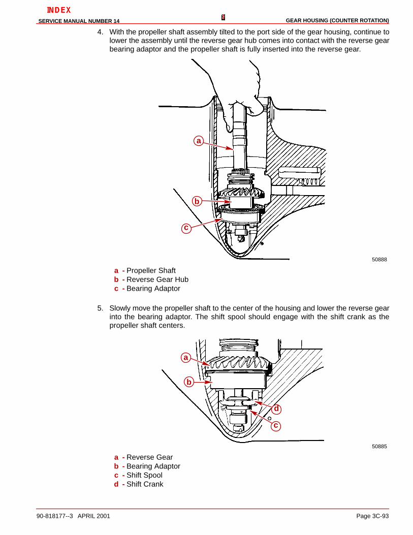
GEAR HOUSING (COUNTER ROTATION)SERVICE MANUAL NUMBER 14
90-818177--3 APRIL 2001 Page 3C-93
4. With the propeller shaft assembly tilted to the port side of the gear housing, continue tolower the assembly until the reverse gear hub comes into contact with the reverse gearbearing adaptor and the propeller shaft is fully inserted into the reverse gear.
50888
a
b
c
a - Propeller Shaftb - Reverse Gear Hubc - Bearing Adaptor
5. Slowly move the propeller shaft to the center of the housing and lower the reverse gearinto the bearing adaptor. The shift spool should engage with the shift crank as thepropeller shaft centers.
50885
c
d
a
b
a - Reverse Gearb - Bearing Adaptorc - Shift Spoold - Shift Crank

GEAR HOUSING (COUNTER ROTATION) SERVICE MANUAL NUMBER 14
Page 3C-94 90-818177--3 APRIL 2001
IMPORTANT: The shift shaft must point forward when the shaft is rotated clockwise.If it does not lift it up slightly and realign the lower shift shaft splines into the shiftcrank. Recheck to make sure that it is now aligned correctly.
6. Operate the shift shaft to ensure that it has been properly installed. The sliding clutchshould move forward when the shift shaft is turned clockwise and should move aft whenthe shift shaft is turned counterclockwise.
7. Torque the screws that secure the shift shaft bushing to 60 lb-in. (6.8 Nm). Recheck theshift shaft alignment as noted in the preceding IMPORTANT statement.
70888
a
b
a - Screws (2)b - Shift Shaft Bushing
8. Slide the rubber sleeve at top end of shift shaft down so that it just touches the oil sealin the bushing.
70492
bc
a
d
a - Shift Shaftb - Rubber Sleevec - Oil Seald - Shift Shaft Bushing

GEAR HOUSING (COUNTER ROTATION)SERVICE MANUAL NUMBER 14
90-818177--3 APRIL 2001 Page 3C-95
Drive Shaft and Pinion Gear
Final Installation1. Place the shim(s) into the drive shaft housing bore at the location shown.
70620
a
a - Shim(s)
NOTE: For ease of installation, glue the washer to the pinion gear using 3M Adhesive orequivalent.
2. Apply Loctite 271 to the threads of the pinion gear nut and place the pinion gear nut(chamfer side toward the pinion gear) into the MR slot of the pinion nut adapter. A smallamount of heavy grease in the slot of the pinion nut adapter will help hold the nut in theadaptor while installing the drive shaft assembly.
3. Place the pinion gear (with the washer glued to it) into the gear housing.
4. Insert the pinion nut adapter (with the nut assembled to it) into the gear housing.
5. Insert the drive shaft into the gear housing drive shaft bore. It may be necessary to rotatethe drive shaft to engage the drive shaft splines into the pinion gear splines.

GEAR HOUSING (COUNTER ROTATION) SERVICE MANUAL NUMBER 14
Page 3C-96 90-818177--3 APRIL 2001
6. Start the pinion nut onto the drive shaft threads by rotating the drive shaft until the nutis snug.
70891
a
b
c
a - Pinion Gear (With The Washer Glued To It)b - Pinion Nut Adaptor (91-61067A3)c - Drive Shaft
7. Install the drive shaft tapered roller bearing cup then the retainer.
70890
ab
a - Tapered Roller Bearing Cupb - Drive Shaft Retainer

GEAR HOUSING (COUNTER ROTATION)SERVICE MANUAL NUMBER 14
90-818177--3 APRIL 2001 Page 3C-97
8. Torque the retainer to 100 lb-ft (130 Nm).
70711
a
a - Drive Shaft Bearing Retainer Wrench (91-43506)
9. Install the bearing carrier into the gear housing backwards to hold the propeller shaft andthe pinion nut adapter in position.
10. Torque the pinion nut by turning the drive shaft using the drive shaft nut wrench andtorque wrench with the appropriate socket, to 70 lb-ft (96 Nm).
70892
a
b
c
a - Pinion Nut Adapter (91-61067A3)b - Drive Shaft Nut Wrench (91-56775)c - Bearing Carrier (installed backwards)
11. Remove the bearing carrier, pinion nut adapter and drive shaft nut wrench.

GEAR HOUSING (COUNTER ROTATION) SERVICE MANUAL NUMBER 14
Page 3C-98 90-818177--3 APRIL 2001
Bearing Carrier Assembly
Final Installation1. Install the appropriate spacer shim into the gear housing.
50782
a
a - Shim
2. Lubricate the thrust bearing with Quicksilver High Performance Gear Lube and placeit onto the forward gear.
50785
a
a - Thrust Bearingb - Forward Gear

GEAR HOUSING (COUNTER ROTATION)SERVICE MANUAL NUMBER 14
90-818177--3 APRIL 2001 Page 3C-99
3. Place the thrust race on top of the thrust bearing with the stepped side up as shownin the following figure.
50785
a
a - Thrust Race
NOTE: The latest style adapter will use a thrust washer to ride against the adapter face.
74886
a
b
a - Thrust Washerb - Thrust Bearing

GEAR HOUSING (COUNTER ROTATION) SERVICE MANUAL NUMBER 14
Page 3C-100 90-818177--3 APRIL 2001
4. Use the Forward Gear Installation Tool (91-815850) to install the forward gear downover the propeller shaft. Ensure that the thrust race seats evenly onto the shim. Tap therace down lightly using a soft punch; do not damage the thrust race surface.
50783
b
a
c
a - Forward Gear Installation Tool (91-815850)b - Forward Gearc - Thrust Race
5. Install the forward gear bearing adaptor using a hook tool (which was fashioned whenthe adaptor was removed) as shown. Ensure that the adaptor seats evenly against thethrust race.
50881
a
b
c
d
a - Hook Toolb - Forward Gear Installation Tool (91-815850)c - Forward Gear Bearing Adaptord - Thrust Race

GEAR HOUSING (COUNTER ROTATION)SERVICE MANUAL NUMBER 14
90-818177--3 APRIL 2001 Page 3C-101
6. Remove the hook tool and, while holding down on the forward gear, remove the forwardgear installation tool by holding the bearing adaptor down with a large screwdriver.
50889
a
b
c
a - Forward Gear Installation Tool (91-815850)b - Forward Gear Bearing Adaptorc - Forward Gear
7. Ensure that the top of the bearing adaptor is clean and install the small thrust race ontop of the bearing adaptor.
50880
a
b
c
a - Thrust Raceb - Forward Gear Bearing Adaptorc - Forward Gear

GEAR HOUSING (COUNTER ROTATION) SERVICE MANUAL NUMBER 14
Page 3C-102 90-818177--3 APRIL 2001
8. Lubricate the small thrust bearing with Quicksilver High Performance Gear Lube andinstall it on top of the thrust race.
50783
a
b
a - Small Thrust Bearingb - Forward Gear Bearing Adaptor
NOTE: The thrust collars have changed. The later model collars are thinner. See “SpecialInformation” page 3C-8. Do not mix earlier style and later style parts.
75223
a
b
a - Earlier Style Thrust Collar (Prior to S/N OF680000)b - Later Style Thrust Collar (S/N OF680000 and after)

GEAR HOUSING (COUNTER ROTATION)SERVICE MANUAL NUMBER 14
90-818177--3 APRIL 2001 Page 3C-103
9. Assemble the thrust collar with its stepped side down toward the small thrust bearing.
50784
b
a
a - Thrust Collarb - Small Thrust Bearing

GEAR HOUSING (COUNTER ROTATION) SERVICE MANUAL NUMBER 14
Page 3C-104 90-818177--3 APRIL 2001
10. Pull up slightly on the propeller shaft to gain access to the groove on the shaft for thekeepers. Assemble the two keepers into the groove and lower the propeller shaft.
50826
a
b
c
a - Propeller Shaft (Slightly Lifted)b - Keepers (2)c - Thrust Collar
50778
a
c b
a - Propeller Shaft (Lowered Into Position)b - Keepersc - Thrust Collar

GEAR HOUSING (COUNTER ROTATION)SERVICE MANUAL NUMBER 14
90-818177--3 APRIL 2001 Page 3C-105
11. Install the second thrust collar with its stepped side up.
50787
b
a
a - Propeller Shaftb - Thrust Collar
12. Lubricate the second thrust bearing with Quicksilver High Performance Gear Lube andinstall it to the top of the thrust collar.
50786
a
b
a - Thrust Bearingb - Thrust Collar

GEAR HOUSING (COUNTER ROTATION) SERVICE MANUAL NUMBER 14
Page 3C-106 90-818177--3 APRIL 2001
13. Lubricate the second small thrust bearing race with Quicksilver High Performance GearLube. Assemble it to the surface inside of the bearing carrier as shown.
50779
b
a
a - Thrust Raceb - Bearing Carrier
14. Lubricate the large O-ring with Quicksilver High Performance Gear Lube and assembleinto the gear housing as shown following.
50886
a
a - O-ring
15. Prepare the bearing carrier for installation as follows:
a. Lubricate the outer diameter of the bearing carrier with Quicksilver Perfect Seal.

GEAR HOUSING (COUNTER ROTATION)SERVICE MANUAL NUMBER 14
90-818177--3 APRIL 2001 Page 3C-107
b. Fill the space between the carrier oil seals with Quicksilver 2-4-C Marine Lubricantwith Teflon.
c. Lubricate the needle bearing with Quicksilver High Performance Gear Lube.
16. Install the bearing carrier assembly into the gear housing.
50826
a
a - Bearing Carrier Assembly
17. Align the bearing carrier “V” shaped notch with the alignment hole in the gear housing.
18. Install the tab washer with the external tab inserted into the hole in the gear housing.
70713
b
ca
a - Gear Case Alignment Holeb - “V” Shaped Notch in Bearing Carrierc - Alignment Tab of Tab Washer

GEAR HOUSING (COUNTER ROTATION) SERVICE MANUAL NUMBER 14
Page 3C-108 90-818177--3 APRIL 2001
19. Ensure that the “V” shaped tab aligns with the “V” notch in bearing carrier.
70714
a
b
a - Tab Washerb - “V” Tab
20. Generously lubricate the bearing carrier retainer threads with Quicksilver Lubricant 101.Start the retainer into the gear housing threads with the notched side down and thenumbered side up. Screw it down fully by hand.
70715
a
a - Bearing Carrier Retainer

GEAR HOUSING (COUNTER ROTATION)SERVICE MANUAL NUMBER 14
90-818177--3 APRIL 2001 Page 3C-109
21. Torque the bearing carrier retainer to 210 lb-ft (285 Nm).
23355
a
a - Bearing Carrier Retainer Wrench (91-61069)
22. Ensure tabs are aligned with notch in retainer nut. Bend one tab aft (outward) into aspace between two of the notches of the retainer. Bend all the remaining tabs forward(inward).
70490
a
b
c
a - Bearing Carrierb - Tabc - Retainer Notches

GEAR HOUSING (COUNTER ROTATION) SERVICE MANUAL NUMBER 14
Page 3C-110 90-818177--3 APRIL 2001
Oil Seal Carrier Assembly
InstallationNOTE: Apply hand pressure only to install the oil seal carrier into position. Do not hammerit into position.
1. Lubricate the oil seal carrier oil seal lips and O-ring with Quicksilver 2-4-C MarineLubricant with Teflon and install the oil seal carrier over the drive shaft and into the gearcase.
70501
ab
c
a - Oil Seal Carrier (Bottom View)b - Oil Seal Lipsc - O-ring
75685
a
b
c
a - Drive Shaftb - Oil Seal Carrierc - Retainer Nut

GEAR HOUSING (COUNTER ROTATION)SERVICE MANUAL NUMBER 14
90-818177--3 APRIL 2001 Page 3C-111
Water Pump Assembly
InstallationNOTE: The aluminum dam has been changed to a rubber filler plug. If the aluminum waterpump dam in the gear housing has become corroded or damaged, it can be replaced withthe rubber filler plug.
1. Install the rubber filler plug or aluminum dam in the gear housing. Earlier models willhave an aluminum dam, later models will have a rubber filler plug. To replace thealuminum dam if it has been removed and undamaged, place a bead of Permatex UltraBlue Silicone Sealant down both sides of it.
71410 71436
ba
a - Aluminum Damb - Rubber Filler Plug
IMPORTANT: The gaskets/face plate hole pattern is not symmetrical. If the holes ofthe gaskets/face plate do not align with the screw holes of the gear case and/or eachother, one or more of the parts is upside down. Determine which part(s) is (are) upsidedown and turn the appropriate part(s) over.
2. Assemble the small hole gasket then the face plate followed by the large hole gasketonto the gear case.
70720
ab
c
a - Small Hole Gasketb - Face Platec - Large Hole Gasket
3. Place a small amount of Quicksilver 2-4-C Marine Lubricant with Teflon on the flatsurface of the impeller key and assemble the key onto the drive shaft keyway.

GEAR HOUSING (COUNTER ROTATION) SERVICE MANUAL NUMBER 14
Page 3C-112 90-818177--3 APRIL 2001
IMPORTANT: When using an impeller whose blades have taken a set, face the curl ofthe blades in a counterclockwise direction. DO NOT install the impeller with itsblades positioned in a reversed direction from original rotation or premature impellerfailure will occur.
4. Assemble the water pump impeller onto the drive shaft and down over the key.
70721
a
b
a - Water Pump Impellerb - Water Pump Impeller Key
5. Install the two (2) water pump locating pins through the gaskets and face plate.
6. Lightly lubricate the inside of the water housing with Quicksilver 2-4-C Marine Lubricantwith Teflon. Position the water pump body over the drive shaft and water pump locatingpins. Rotate the drive shaft in a clockwise direction, while pushing down on the waterpump body to ease the water pump over the impeller blades.
70722
a
b
c
a - Water Pump Bodyb - Water Pump Alignment Pins (91-821571A1)c - Drive Shaft (Turn Clockwise While Installing Water Pump Body)

GEAR HOUSING (COUNTER ROTATION)SERVICE MANUAL NUMBER 14
90-818177--3 APRIL 2001 Page 3C-113
7. Hand start two (2) fasteners into the water pump assembly and remove the water pumplocating pins. Assemble the remaining two (2) fasteners. Run all fasteners down andtorque to 60 lb-in. (7.9 Nm).
IMPORTANT: The water pump face seal must be installed as outlined below.Improperly installing the water pump face seal may result in premature failure of theunit.
8. Lightly lubricate the drive shaft with Quicksilver 2-4-C Marine Lubricant with Teflon.Assemble the water pump face seal to a position approximately 1/2 of the way down thedrive shaft. Assemble the water pump face seal setting tool over the drive shaft and pushthe seal down onto the water pump with the tool while pulling up on the drive shaft.Remove the tool from the drive shaft.
70708
70504a
b
a
a - Water Pump Face Sealb - Water Pump Face Seal Setting Tool
9. Assemble the water tube sleeve into the water tube coupling.
10. Assemble the water tube coupling assembly to the water pump ensuring that the O-ringsare not damaged during assembly.

GEAR HOUSING (COUNTER ROTATION) SERVICE MANUAL NUMBER 14
Page 3C-114 90-818177--3 APRIL 2001
Joining Drive Shaft Housing/Gear Housing
1. Lubricate the end of the water tube (in the drive shaft housing) and the splines of thedrive shaft with Quicksilver 2-4-C Marine Lubricant with Teflon .
NOTE: The aluminum dam has been changed to a rubber filler plug. If the aluminum waterpump dam in the gear housing has become corroded or damaged, it can be replaced withthe rubber filler plug.
IMPORTANT: Ensure that the drain hole of the aluminum water pump dam is notclogged with any foreign material as damage may occur if it is.
71410 71436
abc
Shown Without Water Pump Assembly For Visual Claritya - Aluminum Damb - Rubber Filler Plugc - Drain Hole
2. Units with an aluminum dam installed in them will require a bead of Permatex Ultra BlueSilicone Sealant along the top of the water pump dam as shown. If rubber filler plug ispresent, it is not necessary to use this sealant.
3. To replace the aluminum dam if it has been removed and undamaged, place a bead ofPermatex Ultra Blue Silicone Sealant down both sides of it.

GEAR HOUSING (COUNTER ROTATION)SERVICE MANUAL NUMBER 14
90-818177--3 APRIL 2001 Page 3C-115
4. Ensure that the water pump dam in the drive shaft housing is present and installedcorrectly. Ensure that all parts are present on the gear housing and the drive shafthousing.
70710
a
b
c
a - Drive Shaft Splinesb - Sealant - Aluminum Dam Onlyc - Trim Tab Bolt (Insert In Aft Hole)
5. Install trim tab screw.
6. Position the drive shaft housing straight above the gear housing. Align the water tubesleeve with the water tube and the drive shaft with the upper drive gear. Assemble thedrive shaft housing to the gear housing. It may be necessary to rotate the propeller shaftor the u-joint to align the drive shaft splines with the upper drive gear splines.
7. Assemble the front nut to the front stud of the unit.
8. Assemble the aft screw with the continuity (star) washer (into the forward hole in the trimtab well of the gear housing).
9. Assemble the bolts, nuts and washers to the port and starboard sides of the unit.

GEAR HOUSING (COUNTER ROTATION) SERVICE MANUAL NUMBER 14
Page 3C-116 90-818177--3 APRIL 2001
NOTE: Torque all fasteners as listed in the following figure.
70117
a
b
c
a - Nuts, Bolts, Washers [Torque To 35 lb-ft [47.5 Nm)]b - Nut [Torque To 35 lb-ft [47.5 Nm)]c - Screw [Torque To 28 lb-ft [41 Nm)]
10. Assemble the trim tab and align it to the mark made previously on the gear housing.Torque the screw to 23 lb-ft (31 Nm).
11. Position or lower drive unit so anti-ventilation plate is level.
12. Refill drive unit with gear lube. Refer to Section 1B.

GEAR HOUSING (COUNTER ROTATION)SERVICE MANUAL NUMBER 14
90-818177--3 APRIL 2001 Page 3C-117
THIS PAGE IS INTENTIONALLY BLANK
GEAR HOUSING (COUNTER ROTATION) SERVICE MANUAL NUMBER 14
Page 3C-118 90-818177--3 APRIL 2001
THIS PAGE IS INTENTIONALLY BLANK