Embed Size (px)
Citation preview

5F
FUEL INJECTION DESCRIPTIONS AND SYSTEM OPERATIONSERVICE MANUAL NUMBER 25
90-861328--1 NOVEMBER 1999 Page 5F-1
FUEL SYSTEMSSection 5F - Fuel Injection Descriptions And
System Operation
Table of Contents
Special Tools 5F-2. . . . . . . . . . . . . . . . . . . . . . . Service Precautions 5F-3. . . . . . . . . . . . . . . . . General Information 5F-5. . . . . . . . . . . . . . . . .
Introduction 5F-5. . . . . . . . . . . . . . . . . . . . . . Visual/Physical Inspection 5F-5. . . . . . . . . Basic Knowledge and Tools Required 5F-5Electrostatic Discharge Damage 5F-5. . . . Diagnostic Information 5F-5. . . . . . . . . . . . Wiring Harness Service 5F-6. . . . . . . . . . . Wiring Connector Service 5F-7. . . . . . . . . .
Abbreviations 5F-8. . . . . . . . . . . . . . . . . . . . . . . ECM Self-Diagnostics 5F-9. . . . . . . . . . . . . . . .
Diagnostic Code Tool With Malfunction Indicator Lamp 5F-9. . . Intermittent Malfunction Indicator Lamp 5F-9. . . . . . . . . . . . . . . . . . . Reading Codes 5F-10. . . . . . . . . . . . . . . . . . . Scan Tools 5F-11. . . . . . . . . . . . . . . . . . . . . . . EFI Diagnostic Circuit Check 5F-11. . . . . . . Scan Tool Use With Intermittents 5F-11. . . Non-Scan Diagnosis of Driveability Concerns (With No Codes Set) 5F-12. . . .
Electronic Control Module (ECM) and Sensors 5F-13. . . . . . . . . . . . . . . . . . . . . . .
General Description 5F-13. . . . . . . . . . . . . . . Computers and Voltage Signals 5F-13. . . . Analog Signals 5F-13. . . . . . . . . . . . . . . . . . . Digital Signals 5F-14. . . . . . . . . . . . . . . . . . . . Engine Control Module (ECM) 5F-15. . . . . . Speed Density System 5F-16. . . . . . . . . . . . ECM Input and Sensor Descriptions 5F-17.
Spark Management 5F-22. . . . . . . . . . . . . . . . . . High Energy Ignition with Ignition Control (IC) 5F-22. . . . . . . . . . . . . . Modes Of Operation 5F-23. . . . . . . . . . . . . . Base Ignition Timing 5F-24. . . . . . . . . . . . . . Base Ignition Timing (Continued) 5F-25. . . Results of Incorrect Operation 5F-25. . . . . .
Fuel Metering System 5F-26. . . . . . . . . . . . . . . . General Description 5F-26. . . . . . . . . . . . . . . Cool Fuel Systems 5F-26. . . . . . . . . . . . . . . . Modes of Operation 5F-26. . . . . . . . . . . . . . . Throttle Body Injection Components 5F-28.

FUEL INJECTION DESCRIPTIONS AND SYSTEM OPERATION SERVICE MANUAL NUMBER 25
Page 5F-2 90-861328--1 NOVEMBER 1999
Special Tools
Part Number Tool Name Description
J-34029-A
(Note 1 and 2)High ImpedanceMultimeter (DVM)
Minimum 10 megohm input impedancerequired on all voltage ranges. As amme-ter, accurately measures low value currentflow. As ohmmeter, reads 0-200 ohms,2/20/200 kΩ, 2/20 mΩ.
J-23738Vacuum Pump withGauge - 20 In. HgMinimum
Gauge monitors manifold engine vacuum.Hand pump used to check fuel pressureregulator.
J-34142-B (Note 3) Unpowered TestLight
Used to check circuit wiring, short toground or voltage.
J-34730-2A Injector HarnessTest Light
Visually indicates injector electrical im-pulses from the ECM.
J-35616 Harness TestAdapter
Allows multi-meter connections with wiringharness.
94050mMerCruiser ScanTool Version 3.4(English)
Displays problem codes stored in theECM. It also allows monitoring of variouscircuits and components in the fuel injec-tion system. Allows for test firing injectors.Tool can read MEFI 1 and MEFI 3 ECM.
94008 Code Mate Tester Flashes light to display problem codes.
91-99379 Timing Light Used to check ignition timing. Must haveinductive signal pickup.
91-16850A5 Fuel PressureGauge Kit
Used to check fuel system pressure. Kitincludes 91-803135 Test Port Adaptor Kitand 91-806901 TBI Pressure Valve.
91-823686A2Quicksilver DigitalDiagnostic Terminal(DDT)
Displays problem codes stored in theECM. It also allows monitoring of variouscircuits and components in the fuel injec-tion system.
91-803999 MerCruiser DDTCartridge Version 2
Displays problem codes stored in theECM. It also allows monitoring of variouscircuits and components in the fuel injec-tion system. Tool can read MEFI 1 andMEFI 3 ECM.
84-822560A2 DDT Adaptor Har-ness
Displays problem codes stored in theECM. It also allows monitoring of variouscircuits and components in the fuel injec-tion system.
91-805747A2 EFI Timing Tool Used to set Ignition timing. Plug connectsto DLC.
91-805918A2 Fuel Shutoff Tool Used to perform fuel system pressuretest.
91-806901 Fuel Line Connec-tor
Allows connection of Fuel PressureGauge.
FUEL INJECTION DESCRIPTIONS AND SYSTEM OPERATIONSERVICE MANUAL NUMBER 25
90-861328--1 NOVEMBER 1999 Page 5F-3
Special Tools (continued)
NOTE: 1 The High Impedance Multimeter that comes with the existing Outboard 2 Cycle EFITester, P/N 91-11001A2 meets the requirements listed above.
NOTE: 2 Quicksilver Digital Tachometer / Multi-Meter (DMT 2000) P/N 91-854009A1, meetsthe requirements listed above.
NOTE: 3 Using a test light with 100 mA or less rating may show a faint glow when test actual-ly states no light.
Kent-Moore Tools, Inc.29784 Little MackRoseville, MI 48066Phone: 800-345-2233
Rinda Technologies4563 N. Elston Ave.Chicago, IL 60630Phone: 773-736-6633
Fax: 773-736-2950
E-mail: [email protected]
Service Precautions
The following requirements must be observed:
• Before removing any ECM system component, disconnect the negative battery cable.
• Never start the engine without the battery being solidly connected.
• Never separate the battery from the on-board electrical system while the engine is run-ning.
• Never separate the battery feed wire from the charging system while the engine is run-ning.
• When charging the battery, disconnect it from the boat’s electrical system.
• Ensure that all cable harnesses are connected solidly and that battery connections arethoroughly clean.
• Never connect or disconnect the wiring harness at the ECM when the ignition is switchedON.
• Before attempting any electric arc welding, disconnect the battery leads and the ECMconnector(s).
• When steam cleaning engines, do not direct the steam cleaning nozzle at ECM systemcomponents. If this happens, corrosion of the terminals or damage of components cantake place.
• Use only the test equipment specified in the diagnostic charts, since other test equip-ment may either give incorrect results or damage good components.
• All voltage measurements using a voltmeter require a digital voltmeter with a rating of 10megohms input impedance.
FUEL INJECTION DESCRIPTIONS AND SYSTEM OPERATION SERVICE MANUAL NUMBER 25
Page 5F-4 90-861328--1 NOVEMBER 1999
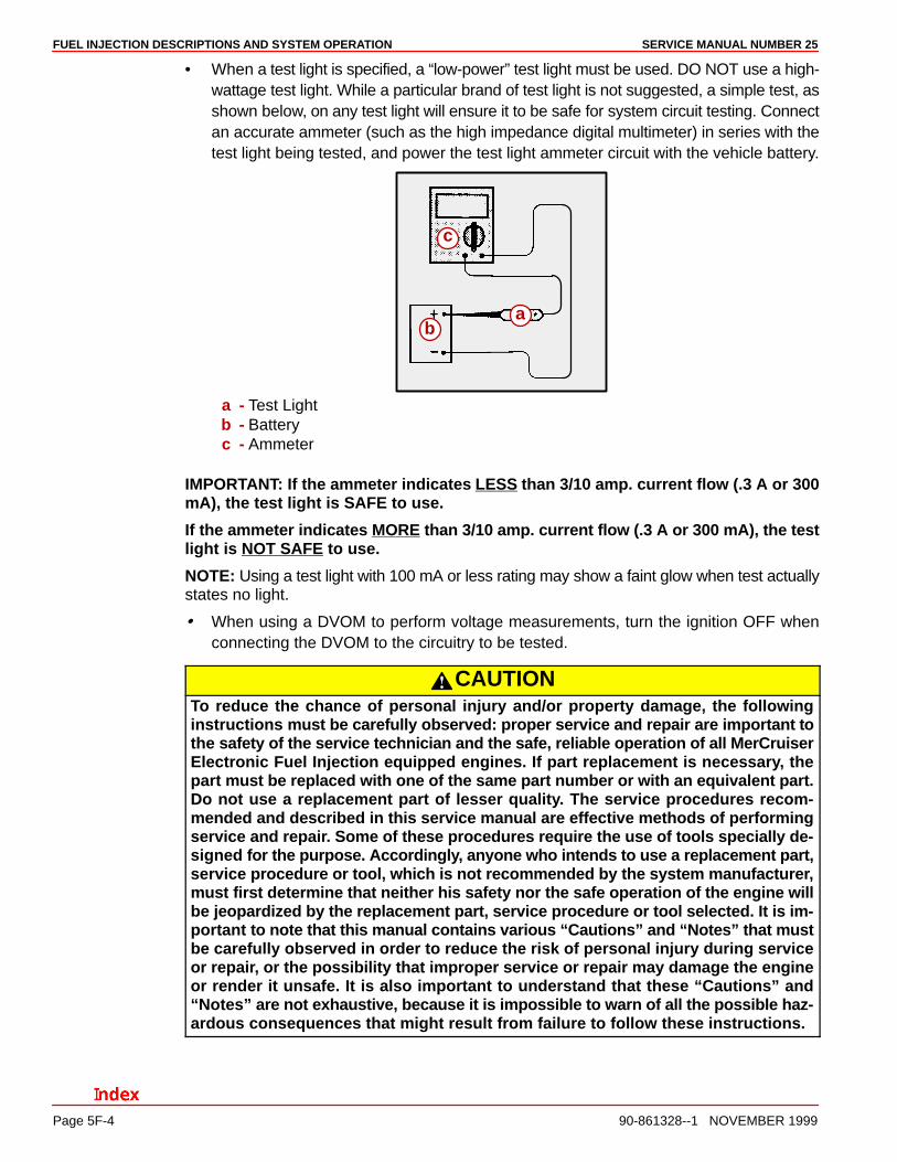
• When a test light is specified, a “low-power” test light must be used. DO NOT use a high-wattage test light. While a particular brand of test light is not suggested, a simple test, asshown below, on any test light will ensure it to be safe for system circuit testing. Connectan accurate ammeter (such as the high impedance digital multimeter) in series with thetest light being tested, and power the test light ammeter circuit with the vehicle battery.
ba
c
a - Test Lightb - Batteryc - Ammeter
IMPORTANT: If the ammeter indicates LESS than 3/10 amp. current flow (.3 A or 300mA), the test light is SAFE to use.
If the ammeter indicates MORE than 3/10 amp. current flow (.3 A or 300 mA), the testlight is NOT SAFE to use.
NOTE: Using a test light with 100 mA or less rating may show a faint glow when test actuallystates no light.
When using a DVOM to perform voltage measurements, turn the ignition OFF whenconnecting the DVOM to the circuitry to be tested.
CAUTIONTo reduce the chance of personal injury and/or property damage, the followinginstructions must be carefully observed: proper service and repair are important tothe safety of the service technician and the safe, reliable operation of all MerCruiserElectronic Fuel Injection equipped engines. If part replacement is necessary, thepart must be replaced with one of the same part number or with an equivalent part.Do not use a replacement part of lesser quality. The service procedures recom-mended and described in this service manual are effective methods of performingservice and repair. Some of these procedures require the use of tools specially de-signed for the purpose. Accordingly, anyone who intends to use a replacement part,service procedure or tool, which is not recommended by the system manufacturer,must first determine that neither his safety nor the safe operation of the engine willbe jeopardized by the replacement part, service procedure or tool selected. It is im-portant to note that this manual contains various “Cautions” and “Notes” that mustbe carefully observed in order to reduce the risk of personal injury during serviceor repair, or the possibility that improper service or repair may damage the engineor render it unsafe. It is also important to understand that these “Cautions” and“Notes” are not exhaustive, because it is impossible to warn of all the possible haz-ardous consequences that might result from failure to follow these instructions.

FUEL INJECTION DESCRIPTIONS AND SYSTEM OPERATIONSERVICE MANUAL NUMBER 25
90-861328--1 NOVEMBER 1999 Page 5F-5
General Information
IntroductionThe following manual has been prepared for effective diagnosis of the MerCruiserElectronic Fuel Injection system.
All information, illustrations and specifications contained in this manual are based on thelatest product information available at the time of publication approval. The right is reservedto make changes at any time without notice.
An understanding of the material contained herein and in subsequent publications issuedwhen necessary, will assist service personnel in properly maintaining the quality to whichMerCruiser engine control systems are built.
Visual/Physical InspectionA careful visual and physical inspection must be performed as part of any diagnosticprocedure. This can often lead to fixing a problem without further steps. Inspect allvacuum hoses for correct routing, pinches, cuts, or disconnects. Be sure to inspect hosesthat are difficult to see. Inspect all the wires in the engine compartment for proper connec-tions, burned or chafed spots, pinched wires, or contact with sharp edges or hot exhaustmanifolds. This visual/physical inspection is very important. It must be done carefully andthoroughly.
Basic Knowledge and Tools RequiredTo use this manual most effectively, a general understanding of basic electrical circuits andcircuit testing tools is required. You should be familiar with wiring diagrams; the meaning ofvolts, ohms and amperes; the basic theories of electricity; and understand what happensin an open or shorted wire. To perform system diagnosis, several special tools and equip-ment are required. Please become acquainted with the tools and their use before attemptingto diagnose the system. Special tools which are required for system service are listed laterin this section (see “Table of Contents”).
Electrostatic Discharge DamageElectronic components are often designed to carry very low voltage and are susceptible todamage caused by electrostatic discharge. It is possible for less than 100 volts of static elec-tricity to cause damage to some electronic components. By comparison, it takes 4,000 voltsfor a person to even feel the effect of a static discharge.
There are several ways for a person to become statically charged. The most common meth-ods of charging are by friction and by induction. An example of charging by friction is a per-son sliding across a seat, in which a charge of as much as 25,000 volts can build up. Charg-ing by induction occurs when a person with well-insulated shoes stands near a highlycharged object and momentarily touches ground. Charges of the same polarity are drainedoff, leaving the person highly charged with the opposite polarity. Static charges of either typecan cause damage. Use care when handling and testing electronic components.
Diagnostic InformationThe diagnostic charts and functional checks in this manual are designed to locate a faultycircuit or component through logic based on the process of elimination. The charts are pre-pared with the requirement that the system functioned correctly at the time of assem-bly and that there are no multiple failures.

FUEL INJECTION DESCRIPTIONS AND SYSTEM OPERATION SERVICE MANUAL NUMBER 25
Page 5F-6 90-861328--1 NOVEMBER 1999
Wiring Harness ServiceMarine engine control circuits contain many special design features not found in standardland vehicle wiring. Environmental protection is used extensively to protect electrical con-tacts and proper splicing methods must be used.
The proper operation of low amperage input/output circuits depends upon good continuitybetween circuit connectors. Before component replacement and/or during normal trouble-shooting procedures, visually inspect any questionable mating connector. Mating surfacesshould be properly formed, clean and likely to make proper contact. Some typical causesof connector problems are listed below.
1. Improperly formed contacts and/or connector housing.
2. Damaged contacts or housing due to improper engagement.
3. Corrosion, sealer or other contaminants on the contact mating surfaces.
4. Incomplete mating of the connector halves during initial assembly or during subsequenttroubleshooting procedures.
5. Tendency for connectors to come apart due to vibration and/or temperature cycling.
6. Terminals not fully seated in the connector body.
7. Inadequate terminal crimps to the wire.
Wire harnesses should be replaced with proper part number harnesses. When signal wiresare spliced into a harness, use the same gauge wire with high temperature insulation only.
With the low current and voltage levels found in the system, it is important that the best pos-sible bond be made at all wire splices by soldering the splices, as shown in the followingillustrations. Use care when probing a connector or replacing connector terminals. It is pos-sible to short between opposite terminals. If this happens, certain components can be dam-aged. Always use jumper wires with the corresponding mating terminals between connec-tors for circuit checking. NEVER probe through connector seals, wire insulation, secondaryignition wires, boots, nipples or covers. Microscopic damage or holes will result in eventualwater intrusion, corrosion and/or component or circuit failure.
WIRE REPAIR
1. Locate damaged wire.
2. Remove insulation as required.
73048
3. Splice two wires together using splice clips and rosin core solder.
73048
4. Cover splice with heat shrink sleeve to insulate from other wires.
73048
FUEL INJECTION DESCRIPTIONS AND SYSTEM OPERATIONSERVICE MANUAL NUMBER 25
90-861328--1 NOVEMBER 1999 Page 5F-7
Wiring Connector ServiceMost connectors in the engine compartment are protected against moisture and dirt thatcould create oxidation and deposits on the terminals. This protection is important becauseof the very low voltage and current levels found in the electronic system. The connectorshave a lock which secures the male and female terminals together. A secondary lock holdsthe seal and terminal into the connector.
When diagnosing, open circuits are often difficult to locate by sight because oxidation or ter-minal misalignment are hidden by the connectors. Merely wiggling a connector on a sensoror in the wiring harness may locate the open circuit condition. This should always be consid-ered when an open circuit or failed sensor is indicated. Intermittent problems may also becaused by oxidized or loose connections.
Before making a connector repair, be certain of the type of connector. Some connectors looksimilar but are serviced differently. Replacement connectors and terminals are listed in theParts Catalog.
Ensure that the connector seals are not deformed or crushed when mating the connectorstogether.

FUEL INJECTION DESCRIPTIONS AND SYSTEM OPERATION SERVICE MANUAL NUMBER 25
Page 5F-8 90-861328--1 NOVEMBER 1999
Abbreviations
in. hg Inches Of Mercury IGN Ignition
BARO Barometric Pressure INJ Injection
BAT Battery Positive Terminal, Bat-tery or System Voltage
kPa Kilopascal
B+ Battery Positive KS Knock Sensor System
CKT Circuit KV Kilovolts
CONN Connector MAP Manifold Absolute Pressure
CYL Cylinder MIL Malfunction Indicator Lamp
DEG Degrees mSec Millisecond
DIAG Diagnostic N/C Normally Closed
DIST Distributor N/O Normally Open
DLC Data Link Connector PROM Programmable Read OnlyMemory
DTC Diagnostic Trouble Code RAM Random Access Memory
DVOM Digital Volt Ohm Meter REF HI Reference High
ECM Engine Control Module REF LO Reference Low
ECT Engine Coolant Temperature
ROM Read Only Memory
EEPROM Electronic Erasable Program-mable Read Only Memory
SLV Slave
HEI High Energy Ignition SW Switch
EMI ElectromagneticInterference
TACH Tachometer
ENG Engine TERM Terminal
GND Ground TP Throttle Position
GPH Gallons Per Hour V Volts
IAC Idle Air Control VAC Vacuum
IAT Intake Air Temperature WOT Wide Open Throttle
IC Ignition Control
FUEL INJECTION DESCRIPTIONS AND SYSTEM OPERATIONSERVICE MANUAL NUMBER 25
90-861328--1 NOVEMBER 1999 Page 5F-9
ECM Self-Diagnostics
The ECM performs a continual self-diagnosis on certain control functions. This diagnosticcapability is complemented by the diagnostic procedures contained in this manual. TheECM’s language for communicating the source of a malfunction is a system of diagnosticcodes. The codes are two digit numbers that can range from 12 to 51. When a malfunctionis detected by the ECM, a code is set and the Malfunction Indicator Lamp is illuminated.
Diagnostic Code Tool With Malfunction Indicator LampThere are various manufacturers of Diagnostic Code Tools. Most Tools are equipped witha Malfunction Indicator Lamp (MIL).
• It informs the service technician that a problem has occurred and that the vessel is inneed of service as soon as reasonably possible.
• It displays Codes stored by the ECM which help the technician diagnose system prob-lems.
As a bulb and system check, the lamp will come ON with the key on and the engine not run-ning. When the engine is started, the light will turn OFF. If the lamp remains ON, the self-diagnostic system has detected a problem. If the problem goes away, the light will go outin most cases after ten seconds, but a code will remain stored in the ECM.
When the lamp remains ON while the engine is running, or when a malfunction is suspecteddue to a driveability problem, “EFI Diagnostic Circuit Check” must be performed. Thesechecks will expose malfunctions which may not be detected if other diagnostics are per-formed prematurely.
Intermittent Malfunction Indicator LampIn the case of an intermittent problem, the Malfunction Indicator Lamp will light for tenseconds and then will go out. However, the corresponding code will be stored in the memoryof the ECM. When unexpected codes appear during the code reading process, one canassume that these codes were set by an intermittent malfunction and could be helpful indiagnosing the system.
An intermittent code may or may not reset. IF IT IS AN INTERMITTENT FAILURE, A DIAG-NOSTIC CODE CHART IS NOT USED. Consult the “Diagnostic Aids” on the same pageas the diagnostic code chart. “Troubleshooting” also covers the topic of “Intermittents.” Aphysical inspection of the applicable sub-system most often will resolve the problem.
FUEL INJECTION DESCRIPTIONS AND SYSTEM OPERATION SERVICE MANUAL NUMBER 25
Page 5F-10 90-861328--1 NOVEMBER 1999
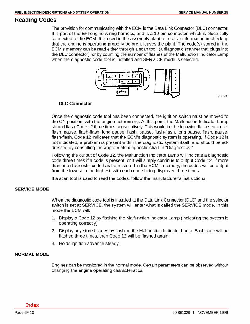
Reading CodesThe provision for communicating with the ECM is the Data Link Connector (DLC) connector.It is part of the EFI engine wiring harness, and is a 10-pin connector, which is electricallyconnected to the ECM. It is used in the assembly plant to receive information in checkingthat the engine is operating properly before it leaves the plant. The code(s) stored in theECM’s memory can be read either through a scan tool, (a diagnostic scanner that plugs intothe DLC connector), or by counting the number of flashes of the Malfunction Indicator Lampwhen the diagnostic code tool is installed and SERVICE mode is selected.
73053
DLC Connector
Once the diagnostic code tool has been connected, the ignition switch must be moved tothe ON position, with the engine not running. At this point, the Malfunction Indicator Lampshould flash Code 12 three times consecutively. This would be the following flash sequence:flash, pause, flash-flash, long pause, flash, pause, flash-flash, long pause, flash, pause,flash-flash. Code 12 indicates that the ECM’s diagnostic system is operating. If Code 12 isnot indicated, a problem is present within the diagnostic system itself, and should be ad-dressed by consulting the appropriate diagnostic chart in “Diagnostics.”
Following the output of Code 12, the Malfunction Indicator Lamp will indicate a diagnosticcode three times if a code is present, or it will simply continue to output Code 12. If morethan one diagnostic code has been stored in the ECM’s memory, the codes will be outputfrom the lowest to the highest, with each code being displayed three times.
If a scan tool is used to read the codes, follow the manufacturer’s instructions.
SERVICE MODE
When the diagnostic code tool is installed at the Data Link Connector (DLC) and the selectorswitch is set at SERVICE, the system will enter what is called the SERVICE mode. In thismode the ECM will:
1. Display a Code 12 by flashing the Malfunction Indicator Lamp (indicating the system isoperating correctly).
2. Display any stored codes by flashing the Malfunction Indicator Lamp. Each code will beflashed three times, then Code 12 will be flashed again.
3. Holds ignition advance steady.
NORMAL MODE
Engines can be monitored in the normal mode. Certain parameters can be observed withoutchanging the engine operating characteristics.
FUEL INJECTION DESCRIPTIONS AND SYSTEM OPERATIONSERVICE MANUAL NUMBER 25
90-861328--1 NOVEMBER 1999 Page 5F-11
Scan ToolsThe ECM can communicate a variety of information through the DLC connector. This datais transmitted at a high frequency which requires a scan tool for interpretation.
With an understanding of the data which the tool displays, and knowledge of the circuits in-volved, the tool can be very useful in obtaining information which would be more difficult orimpossible to obtain with other equipment.
Scan tools do not make the use of diagnostic charts unnecessary, nor can they indicate ex-actly where a problem is in a particular circuit. Diagnostic tables incorporate diagnosis pro-cedures using a scan tool where possible or a Diagnostic Code Tool (non-scan) if a scantool is unavailable.
EFI Diagnostic Circuit CheckAfter the visual/physical inspection, the On Board Diagnostic (OBD) Circuit Check is thestarting point for all diagnostic procedures. Refer to SECTION 5I.
The correct procedure to diagnose a problem is to follow two basic steps.
1. Are the on-board diagnostics working? This is determined by performing the On BoardDiagnostic Circuit Check. Since this is the starting point for the diagnostic procedures,always begin here. If the on-board diagnostics are not working, the EFI Diagnostic Cir-cuit Check will lead to a diagnostic chart in “Diagnostics” to correct the problem. If theon-board diagnostics are working correctly, go to step 2.
2. If a code is stored, go directly to the numbered code chart in SECTION 5I. This will deter-mine if the fault is still present.
Scan Tool Use With IntermittentsThe scan tool allows manipulation of wiring harnesses or components with the engine notrunning, while observing the scan tool readout.
The scan tool can be plugged in and observed while running the vessel under the conditionwhen the Malfunction Indicator Lamp turns ON momentarily or when the engine driveabilityis momentarily poor. If the problem seems to be related to certain parameters that can bechecked on the scan tool, they should be checked while running the vessel. If there doesnot seem to be any correlation between the problem and any specific circuit, the scan toolcan be checked on each position, watching for a period of time to see if there is any changein the readings that indicates intermittent operation.
The scan tool is also an easy way to compare the operating parameters of a poorly operatingengine with those of a known good one. For example, a sensor may shift in value but notset a trouble code. Comparing the senor’s readings with those of the typical scan tool datareadings may uncover the problem.
The scan tool has the ability to save time in diagnosis and prevent the replacement of goodparts. The key to using the scan tool successfully for diagnosis lies in the technician’s abilityto understand the system he is trying to diagnose as well as an understanding of the scantool operation and limitations. The technician should read the tool manufacturer’s operatingmanual to become familiar with the tool’s operation.

FUEL INJECTION DESCRIPTIONS AND SYSTEM OPERATION SERVICE MANUAL NUMBER 25
Page 5F-12 90-861328--1 NOVEMBER 1999
Non-Scan Diagnosis of Driveability Concerns (With No Codes Set)If a driveability concern still exists after following the diagnostic circuit check and reviewing“Troubleshooting,” an out-of-range sensor may be suspected. Because of the unique de-sign of the EFI system, fail-safes have been incorporated into the ECM to replace a sensedvalue with a default value in the case of a sensor malfunction or sensor wiring concern. Byallowing this to occur, limited engine performance is restored until the vessel is repaired. Abasic understanding of sensor operation is necessary in order to diagnose an out-of-rangesensor.
If the sensor is within its working or acceptable parameters, as shown, the ECM does notdetect a problem. If the sensor should happen to fall out of this “window,” a code will bestored. A known default value will replace the sensed value to restore engine performance.
If the sensor is out of range, but still within the operating window of the ECM, the problemwill go undetected by the ECM and may result in trouble later.
A good example of this would be if the coolant sensor was reading incorrectly and indicatingto the ECM that coolant temperature was at 20° F, but actual coolant temperature was 175°F. This would cause the ECM to deliver more fuel than was actually needed and result inan overly rich, rough running condition. This condition would not have caused a code to setas the ECM interprets this as within its range.
To identify a sensor which is out of range, unplug it while running the engine. After approxi-mately two minutes, the diagnostic code for that sensor will set, a code, and replace thesensed value with a default value. If at that point a noticeable performance increase is ob-served, the non-scan code chart for that particular sensor should be followed to correct theproblem.
NOTE: Be sure to clear each code after disconnecting and reconnecting each sensor. Fail-ure to do so may result in a misdiagnosis of the problem.

FUEL INJECTION DESCRIPTIONS AND SYSTEM OPERATIONSERVICE MANUAL NUMBER 25
90-861328--1 NOVEMBER 1999 Page 5F-13
Electronic Control Module (ECM) and Sensors
General DescriptionThe MerCruiser Electronic Fuel Injection system is equipped with a computer that providesthe operator with state-of-the-art control of fuel and spark delivery. Computers use voltageto send and receive information.
Computers and Voltage SignalsVoltage is electrical pressure. Voltage does not flow in circuits. Instead, voltage causes cur-rent. Current does the real work in electrical circuits. It is current, the flow of electricallycharged particles, that energizes solenoids, closes relays and lights lamps.
Besides causing currents in circuits, voltage can be used as a signal. Voltage signals cansend information by changing levels, changing waveform (shape), or changing the speedat which the signal switches from one level to another. Computers use voltage signals tocommunicate with one another. The different sections inside computers also use voltagesignals to communicate with each other.
There are two kinds of voltage signals, analog and digital. Both of these are used in comput-er systems. It’s important to understand the difference between them and the different waysthey are used.
Analog SignalsAn analog signal is continuously variable. This means that the signal can be any voltagewithin a certain range. An analog signal usually gives information about a condition thatchanges continuously over a certain range. For example, in a marine engine, temperatureis usually provided by an analog signal. There are two general types of sensors that produceanalog signals: the 3-wire and the 2-wire sensor.
THREE-WIRE SENSORS (MAP AND TP)
The following figure shows a schematic representation of a 3-wire sensor. All 3-wire sensorshave a reference voltage, a ground and a variable “wiper.” The lead coming off of the wiperwill be the signal to the Engine Control Module (ECM). As this wiper position changes, thesignal voltage returned to the computer also changes.
ab
c
d
3-Wire Sensora - Typical Sensorb - ECMc - Voltage Outd - Signal Inpute - Sensor Ground
FUEL INJECTION DESCRIPTIONS AND SYSTEM OPERATION SERVICE MANUAL NUMBER 25
Page 5F-14 90-861328--1 NOVEMBER 1999
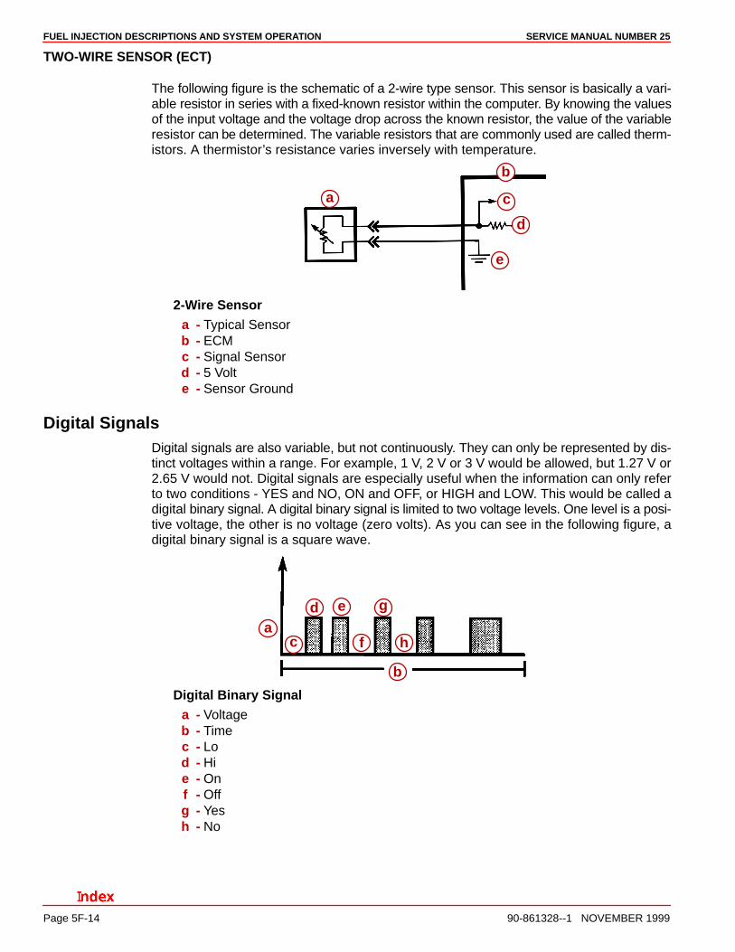
TWO-WIRE SENSOR (ECT)
The following figure is the schematic of a 2-wire type sensor. This sensor is basically a vari-able resistor in series with a fixed-known resistor within the computer. By knowing the valuesof the input voltage and the voltage drop across the known resistor, the value of the variableresistor can be determined. The variable resistors that are commonly used are called therm-istors. A thermistor’s resistance varies inversely with temperature.
a
b
c
d
e
2-Wire Sensora - Typical Sensorb - ECMc - Signal Sensord - 5 Volte - Sensor Ground
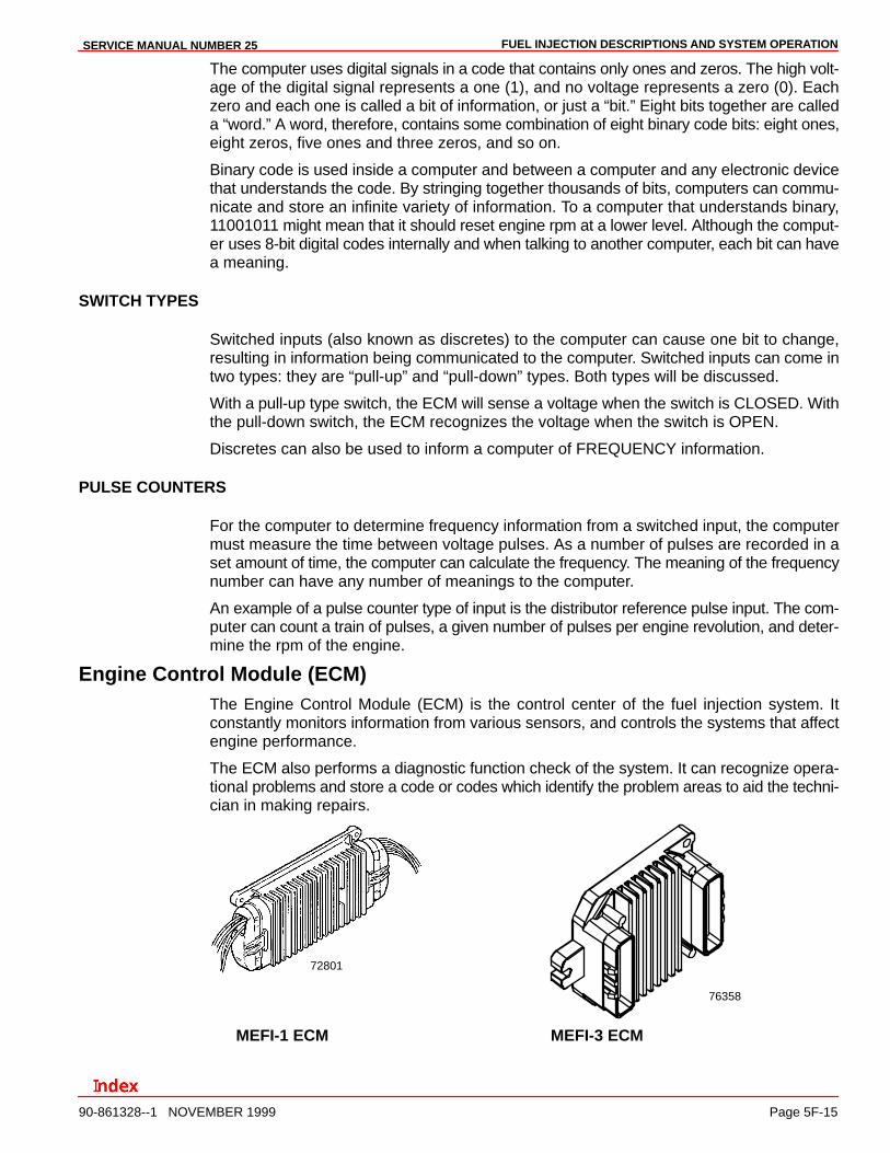
Digital SignalsDigital signals are also variable, but not continuously. They can only be represented by dis-tinct voltages within a range. For example, 1 V, 2 V or 3 V would be allowed, but 1.27 V or2.65 V would not. Digital signals are especially useful when the information can only referto two conditions - YES and NO, ON and OFF, or HIGH and LOW. This would be called adigital binary signal. A digital binary signal is limited to two voltage levels. One level is a posi-tive voltage, the other is no voltage (zero volts). As you can see in the following figure, adigital binary signal is a square wave.
a
b
c
d e
f
g
h
Digital Binary Signala - Voltageb - Timec - Lod - Hie - Onf - Offg - Yesh - No
FUEL INJECTION DESCRIPTIONS AND SYSTEM OPERATIONSERVICE MANUAL NUMBER 25
90-861328--1 NOVEMBER 1999 Page 5F-15
The computer uses digital signals in a code that contains only ones and zeros. The high volt-age of the digital signal represents a one (1), and no voltage represents a zero (0). Eachzero and each one is called a bit of information, or just a “bit.” Eight bits together are calleda “word.” A word, therefore, contains some combination of eight binary code bits: eight ones,eight zeros, five ones and three zeros, and so on.
Binary code is used inside a computer and between a computer and any electronic devicethat understands the code. By stringing together thousands of bits, computers can commu-nicate and store an infinite variety of information. To a computer that understands binary,11001011 might mean that it should reset engine rpm at a lower level. Although the comput-er uses 8-bit digital codes internally and when talking to another computer, each bit can havea meaning.
SWITCH TYPES
Switched inputs (also known as discretes) to the computer can cause one bit to change,resulting in information being communicated to the computer. Switched inputs can come intwo types: they are “pull-up” and “pull-down” types. Both types will be discussed.
With a pull-up type switch, the ECM will sense a voltage when the switch is CLOSED. Withthe pull-down switch, the ECM recognizes the voltage when the switch is OPEN.
Discretes can also be used to inform a computer of FREQUENCY information.
PULSE COUNTERS
For the computer to determine frequency information from a switched input, the computermust measure the time between voltage pulses. As a number of pulses are recorded in aset amount of time, the computer can calculate the frequency. The meaning of the frequencynumber can have any number of meanings to the computer.
An example of a pulse counter type of input is the distributor reference pulse input. The com-puter can count a train of pulses, a given number of pulses per engine revolution, and deter-mine the rpm of the engine.
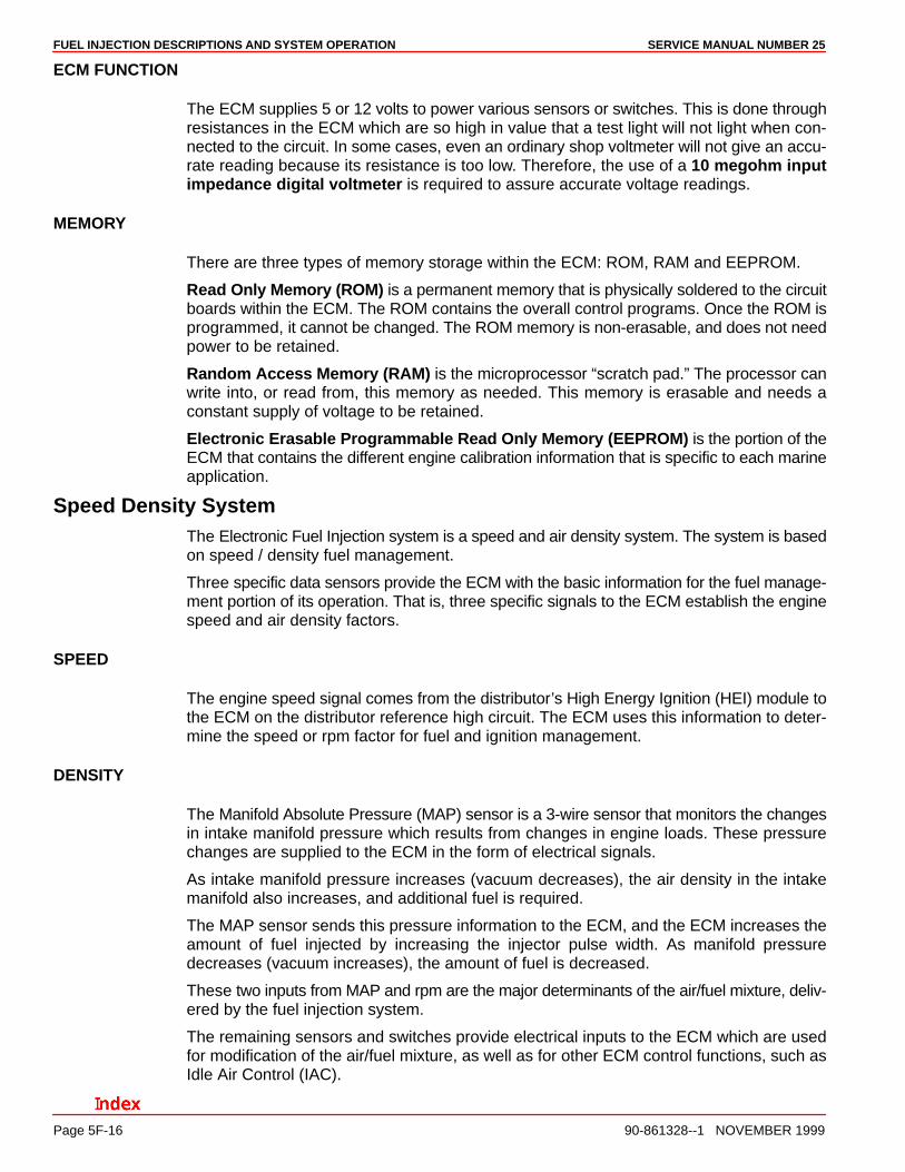
Engine Control Module (ECM)The Engine Control Module (ECM) is the control center of the fuel injection system. Itconstantly monitors information from various sensors, and controls the systems that affectengine performance.
The ECM also performs a diagnostic function check of the system. It can recognize opera-tional problems and store a code or codes which identify the problem areas to aid the techni-cian in making repairs.
72801
76358
MEFI-1 ECM MEFI-3 ECM
FUEL INJECTION DESCRIPTIONS AND SYSTEM OPERATION SERVICE MANUAL NUMBER 25
Page 5F-16 90-861328--1 NOVEMBER 1999
ECM FUNCTION
The ECM supplies 5 or 12 volts to power various sensors or switches. This is done throughresistances in the ECM which are so high in value that a test light will not light when con-nected to the circuit. In some cases, even an ordinary shop voltmeter will not give an accu-rate reading because its resistance is too low. Therefore, the use of a 10 megohm inputimpedance digital voltmeter is required to assure accurate voltage readings.
MEMORY
There are three types of memory storage within the ECM: ROM, RAM and EEPROM.
Read Only Memory (ROM) is a permanent memory that is physically soldered to the circuitboards within the ECM. The ROM contains the overall control programs. Once the ROM isprogrammed, it cannot be changed. The ROM memory is non-erasable, and does not needpower to be retained.
Random Access Memory (RAM) is the microprocessor “scratch pad.” The processor canwrite into, or read from, this memory as needed. This memory is erasable and needs aconstant supply of voltage to be retained.
Electronic Erasable Programmable Read Only Memory (EEPROM) is the portion of theECM that contains the different engine calibration information that is specific to each marineapplication.
Speed Density SystemThe Electronic Fuel Injection system is a speed and air density system. The system is basedon speed / density fuel management.
Three specific data sensors provide the ECM with the basic information for the fuel manage-ment portion of its operation. That is, three specific signals to the ECM establish the enginespeed and air density factors.
SPEED
The engine speed signal comes from the distributor’s High Energy Ignition (HEI) module tothe ECM on the distributor reference high circuit. The ECM uses this information to deter-mine the speed or rpm factor for fuel and ignition management.
DENSITY
The Manifold Absolute Pressure (MAP) sensor is a 3-wire sensor that monitors the changesin intake manifold pressure which results from changes in engine loads. These pressurechanges are supplied to the ECM in the form of electrical signals.
As intake manifold pressure increases (vacuum decreases), the air density in the intakemanifold also increases, and additional fuel is required.
The MAP sensor sends this pressure information to the ECM, and the ECM increases theamount of fuel injected by increasing the injector pulse width. As manifold pressuredecreases (vacuum increases), the amount of fuel is decreased.
These two inputs from MAP and rpm are the major determinants of the air/fuel mixture, deliv-ered by the fuel injection system.
The remaining sensors and switches provide electrical inputs to the ECM which are usedfor modification of the air/fuel mixture, as well as for other ECM control functions, such asIdle Air Control (IAC).
FUEL INJECTION DESCRIPTIONS AND SYSTEM OPERATIONSERVICE MANUAL NUMBER 25
90-861328--1 NOVEMBER 1999 Page 5F-17
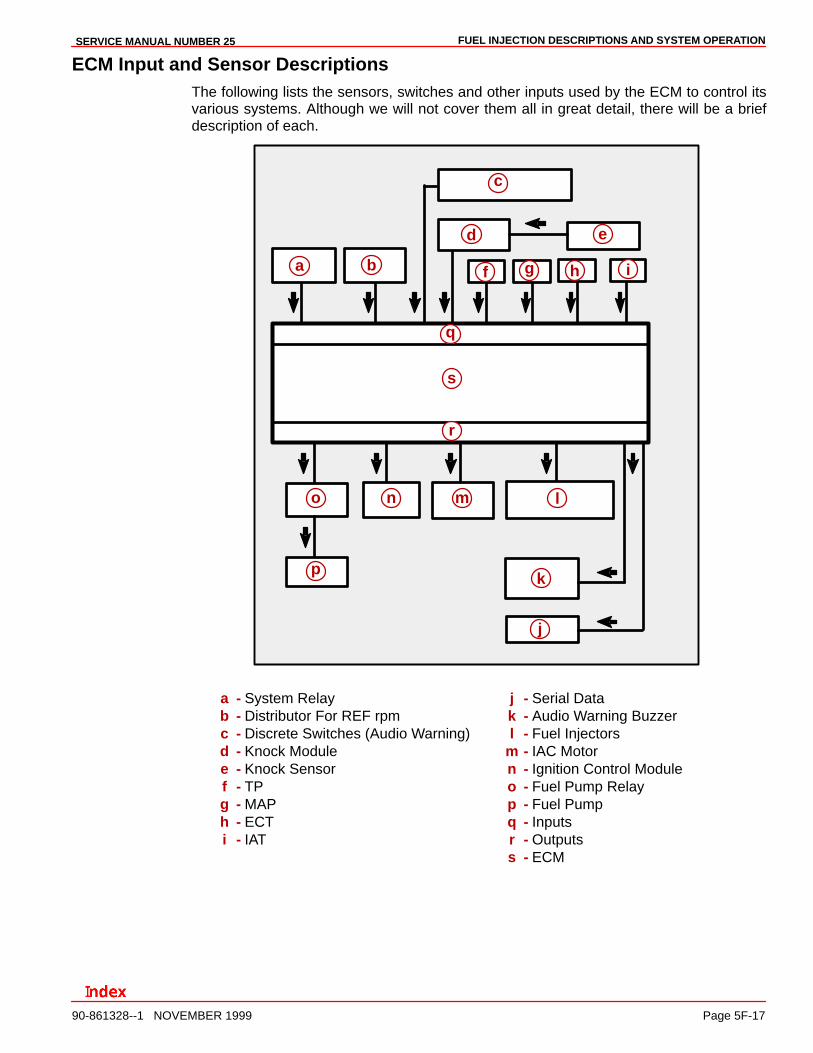
ECM Input and Sensor DescriptionsThe following lists the sensors, switches and other inputs used by the ECM to control itsvarious systems. Although we will not cover them all in great detail, there will be a briefdescription of each.
a b
c
d e
f g h i
j
k
lmno
p
q
r
s
a - System Relayb - Distributor For REF rpmc - Discrete Switches (Audio Warning)d - Knock Modulee - Knock Sensorf - TPg - MAPh - ECTi - IAT
j - Serial Datak - Audio Warning Buzzerl - Fuel Injectors
m - IAC Motorn - Ignition Control Moduleo - Fuel Pump Relayp - Fuel Pumpq - Inputsr - Outputss - ECM
FUEL INJECTION DESCRIPTIONS AND SYSTEM OPERATION SERVICE MANUAL NUMBER 25
Page 5F-18 90-861328--1 NOVEMBER 1999
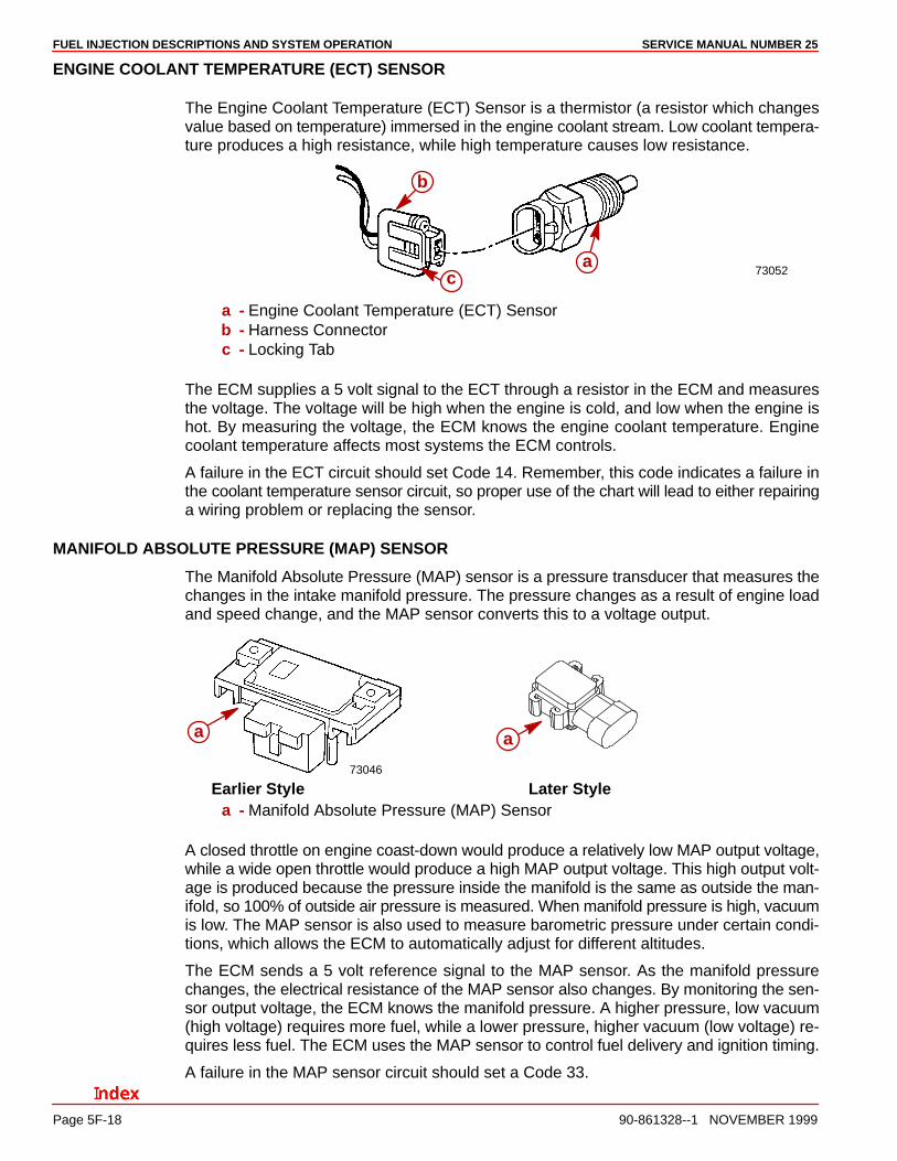
ENGINE COOLANT TEMPERATURE (ECT) SENSOR
The Engine Coolant Temperature (ECT) Sensor is a thermistor (a resistor which changesvalue based on temperature) immersed in the engine coolant stream. Low coolant tempera-ture produces a high resistance, while high temperature causes low resistance.
73052a
b
c
a - Engine Coolant Temperature (ECT) Sensorb - Harness Connectorc - Locking Tab
The ECM supplies a 5 volt signal to the ECT through a resistor in the ECM and measuresthe voltage. The voltage will be high when the engine is cold, and low when the engine ishot. By measuring the voltage, the ECM knows the engine coolant temperature. Enginecoolant temperature affects most systems the ECM controls.
A failure in the ECT circuit should set Code 14. Remember, this code indicates a failure inthe coolant temperature sensor circuit, so proper use of the chart will lead to either repairinga wiring problem or replacing the sensor.
MANIFOLD ABSOLUTE PRESSURE (MAP) SENSOR
The Manifold Absolute Pressure (MAP) sensor is a pressure transducer that measures thechanges in the intake manifold pressure. The pressure changes as a result of engine loadand speed change, and the MAP sensor converts this to a voltage output.
73046
a a
Earlier Style Later Stylea - Manifold Absolute Pressure (MAP) Sensor
A closed throttle on engine coast-down would produce a relatively low MAP output voltage,while a wide open throttle would produce a high MAP output voltage. This high output volt-age is produced because the pressure inside the manifold is the same as outside the man-ifold, so 100% of outside air pressure is measured. When manifold pressure is high, vacuumis low. The MAP sensor is also used to measure barometric pressure under certain condi-tions, which allows the ECM to automatically adjust for different altitudes.
The ECM sends a 5 volt reference signal to the MAP sensor. As the manifold pressurechanges, the electrical resistance of the MAP sensor also changes. By monitoring the sen-sor output voltage, the ECM knows the manifold pressure. A higher pressure, low vacuum(high voltage) requires more fuel, while a lower pressure, higher vacuum (low voltage) re-quires less fuel. The ECM uses the MAP sensor to control fuel delivery and ignition timing.
A failure in the MAP sensor circuit should set a Code 33.
FUEL INJECTION DESCRIPTIONS AND SYSTEM OPERATIONSERVICE MANUAL NUMBER 25
90-861328--1 NOVEMBER 1999 Page 5F-19
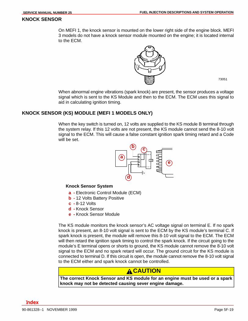
KNOCK SENSOR
On MEFI 1, the knock sensor is mounted on the lower right side of the engine block. MEFI3 models do not have a knock sensor module mounted on the engine; it is located internalto the ECM.
73051
When abnormal engine vibrations (spark knock) are present, the sensor produces a voltagesignal which is sent to the KS Module and then to the ECM. The ECM uses this signal toaid in calculating ignition timing.
KNOCK SENSOR (KS) MODULE (MEFI 1 MODELS ONLY)
When the key switch is turned on, 12 volts are supplied to the KS module B terminal throughthe system relay. If this 12 volts are not present, the KS module cannot send the 8-10 voltsignal to the ECM. This will cause a false constant ignition spark timing retard and a Codewill be set.
ea
b c
d
Knock Sensor Systema - Electronic Control Module (ECM)b - 12 Volts Battery Positivec - 8-12 Voltsd - Knock Sensore - Knock Sensor Module
The KS module monitors the knock sensor’s AC voltage signal on terminal E. If no sparkknock is present, an 8-10 volt signal is sent to the ECM by the KS module’s terminal C. Ifspark knock is present, the module will remove this 8-10 volt signal to the ECM. The ECMwill then retard the ignition spark timing to control the spark knock. If the circuit going to themodule’s E terminal opens or shorts to ground, the KS module cannot remove the 8-10 voltsignal to the ECM and no spark retard will occur. The ground circuit for the KS module isconnected to terminal D. If this circuit is open, the module cannot remove the 8-10 volt signalto the ECM either and spark knock cannot be controlled.
CAUTIONThe correct Knock Sensor and KS module for an engine must be used or a sparkknock may not be detected causing sever engine damage.
FUEL INJECTION DESCRIPTIONS AND SYSTEM OPERATION SERVICE MANUAL NUMBER 25
Page 5F-20 90-861328--1 NOVEMBER 1999
KNOCK SENSOR CIRCUITRY (MEFI-3 MODELS ONLY)
The MEFI-3 ECM is used with the knock sensor to control spark knock. The KS module cir-cuitry is within the MEFI-3 ECM. When spark knock is present, a small AC voltage signalis sent from the knock sensor to the ECM through pin connector J1-30. (If the engine hasa second KS, its voltage signal goes through pin connector J1-14). An AC voltage monitorinside the ECM will detect the spark knock and start retarding spark timing. A Code will beset only if the ECM does not see any activity on the KS signal circuit(s).
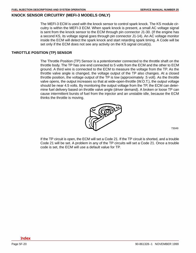
THROTTLE POSITION (TP) SENSOR
The Throttle Position (TP) Sensor is a potentiometer connected to the throttle shaft on thethrottle body. The TP has one end connected to 5 volts from the ECM and the other to ECMground. A third wire is connected to the ECM to measure the voltage from the TP. As thethrottle valve angle is changed, the voltage output of the TP also changes. At a closedthrottle position, the voltage output of the TP is low (approximately .5 volt). As the throttlevalve opens, the output increases so that at wide-open-throttle (W.O.T.), the output voltageshould be near 4.5 volts. By monitoring the output voltage from the TP, the ECM can deter-mine fuel delivery based on throttle valve angle (driver demand). A broken or loose TP cancause intermittent bursts of fuel from the injector and an unstable idle, because the ECMthinks the throttle is moving.
73049
If the TP circuit is open, the ECM will set a Code 21. If the TP circuit is shorted, and a troubleCode 21 will be set. A problem in any of the TP circuits will set a Code 21. Once a troublecode is set, the ECM will use a default value for TP.
FUEL INJECTION DESCRIPTIONS AND SYSTEM OPERATIONSERVICE MANUAL NUMBER 25
90-861328--1 NOVEMBER 1999 Page 5F-21
DISTRIBUTOR REFERENCE (DIST REF)
The distributor reference (engine speed signal) is supplied to the ECM by way of the “DistRef Hi” line from the High Energy Ignition (HEI). This pulse counter type input creates thetiming signal for the pulsing of the fuel injectors, as well as the Ignition Control (IC) functions.This signal is used for a number of control and testing functions within the ECM.
DISCRETE SWITCH INPUTS
Several discrete switch inputs are utilized by the system to identify abnormal conditions thatmay affect engine operation. These switches are used in conjunction with the ECM to detectcritical conditions to engine operation.
The switches which are used with the fuel injection system to detect critical engine operationparameters are:
Switch Normal State
Oil Pressure N/O(With Pressure)
Gear Lube MonitorLevel on Sterndrive
N/O(When Full)
FUEL INJECTION DESCRIPTIONS AND SYSTEM OPERATION SERVICE MANUAL NUMBER 25
Page 5F-22 90-861328--1 NOVEMBER 1999
Spark Management
High Energy Ignition with Ignition Control (IC)The Electronic Fuel Injection is controlled by an Engine Control Module (ECM). This moduleis the nerve/decision center of the system. It uses all the information it gathers to manageignition spark, delivering increased fuel economy and maximum engine performance.
The system uses inputs from sensors to make decisions on the amount of spark advanceor retard allowed.
The system has been designed to control ignition advance and retard electronically by theECM.
In order for the ECM to properly calculate spark advance, it must always know at what speedthe engine is running. The engine speed signal is accomplished by a circuit within the distrib-utor module which converts the pickup coil voltage to a square wave reference signal thatcan be used by the ECM. This square wave engine speed reference signal is known as REFHI. With MEFI 1, the ECM must also have something to compare the REF HI value against.Therefore, an additional line is provided between the ECM and the distributor module thatis known as REF LO. These two lines, between the ECM and the distributor, provide a pre-cise indication of engine speed.
With MEFI 1, the two other lines between the ECM and distributor that control the IgnitionControl (IC) operation are known as the bypass and IC circuits.
FUEL INJECTION DESCRIPTIONS AND SYSTEM OPERATIONSERVICE MANUAL NUMBER 25
90-861328--1 NOVEMBER 1999 Page 5F-23
Modes Of Operation
DISTRIBUTOR MODULE MODE (MEFI 1 ONLY)
The ignition system operates independent of the ECM. The distributor module module inthe distributor maintains a base ignition timing and is able to advance timing to a total of 27degrees. This mode is in control when a Code 42 is detected while engine is running andwill have a noticeable effect on engine operation.
The following describes IC operation during cranking and when the engine starts running.To help understand how IC circuits operate, a relay with a double set of contact points isshown in the IC module (refer to the figures “Ignition Control Mode” and “ECM ControlMode”). Solid state circuitry is used in the module, but showing the relay makes it easier tovisualize how the IC module functions.
During cranking, the relay is in the de-energized position (see figure “Distributor ModuleMode”). This connects the pickup coil to the base of the transistor via the signal converter.When the pickup coil applies a positive voltage to the transistor, the transistor turns ON.When voltage is removed, the transistor turns OFF. When the transistor turns ON, currentflows through the primary winding of the ignition coil. When it turns OFF, the primary currentstops and a spark is developed at the spark plug. A small amount of advance is built intothe IC module via a timing circuit, in case the engine remains in the ignition module timingmode.
With the relay de-energized, a set of contacts (shown closed) would ground the IC line sig-nal.
ECM CONTROL MODE
The ECM control mode controls the ignition timing. The ECM calculates the desired ignitiontiming based on information it gets from its input sensors.
(MEFI 1) When the engine rpm reaches a predetermined value (for this example, 300 rpm),the ECM considers the engine running and applies five volts on the bypass line to the ICmodule. This energizes the relay and causes the contacts from the pickup coil as well asthe grounding contacts for the IC line to open (see figure “ECM Control Mode”). This con-nects the IC line to the base of the transistor, and bypasses the ignition module timing con-trol.
The IC system is now controlled by the IC signal from the ECM and the time at which thespark occurs can be determined by a variable time circuit in the ECM.
FUEL INJECTION DESCRIPTIONS AND SYSTEM OPERATION SERVICE MANUAL NUMBER 25
Page 5F-24 90-861328--1 NOVEMBER 1999
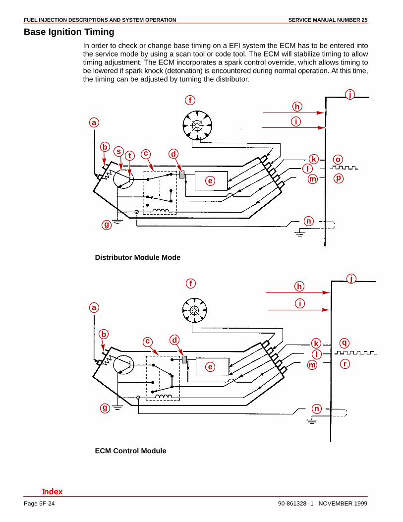
Base Ignition TimingIn order to check or change base timing on a EFI system the ECM has to be entered intothe service mode by using a scan tool or code tool. The ECM will stabilize timing to allowtiming adjustment. The ECM incorporates a spark control override, which allows timing tobe lowered if spark knock (detonation) is encountered during normal operation. At this time,the timing can be adjusted by turning the distributor.
p
o
n
ml
k
j
i
h
g
f
e
dcb
a
ts
Distributor Module Mode
j
k
n
ml
r
q
i
h
g
f
e
dcb
a
ECM Control Module
FUEL INJECTION DESCRIPTIONS AND SYSTEM OPERATIONSERVICE MANUAL NUMBER 25
90-861328--1 NOVEMBER 1999 Page 5F-25
Base Ignition Timing (Continued)a - Ignition Coil Trigger Signalb - Batteryc - Relayd - Module Advancee - Signal Converterf - Pick Up Coilg - Groundh - Manifoldi - Coolant Temperaturej - ECMk - ICl - REF HI
m - Bypassn - REF LOo - Groundedp - No Voltage Appliedq - Not Groundedr - Voltage Applied
Results of Incorrect OperationOpen IC Line from the ECM to the Distributor Module - While the engine is cranking, theECM expects to see the IC signal pulled to virtually zero because it is grounded in the distrib-utor module. Since the IC line is open, it cannot be grounded by the module and the IC signalwill be able to rise and fall, or do what is called toggling. The ECM recognizes the togglingas an abnormal condition, and will not apply bypass voltage to the distributor module whenthe engine reaches run rpm.
Since bypass voltage is not applied to the relay, it remains open and the engine continuesto run on the pickup coil triggering in the ignition module timing mode.
If this condition occurs while the engine is running, the engine will stop, but it will restart andrun in the ignition module timing mode with reduced power.
Grounded IC Line - During cranking, the IC voltage is at virtually zero so the ECM doesnot recognize a problem. When engine rpm reaches the value for the run condition, the ECMapplies bypass voltage to the distributor module. Bypass voltage on the module switchesthe distributor power transistor to the IC line. Because the IC line is grounded, it will haveno voltage applied so it cannot operate the power transistor to enter the IC mode.
If the IC line becomes grounded while the engine is being operated, the engine will stop andwill be difficult to restart.
An open or ground in the IC or bypass will cause the engine to run on the distributor moduletiming. This will cause reduced performance, poor fuel economy and erratic idle.
Grounded or Open Bypass Line - While the engine is cranking, the IC line will be groundedand the ECM will not notice anything abnormal. When run rpm is reached, the ECM appliesbypass voltage to the bypass line but because of the ground or open, it will not be able toenergize the relay. Therefore, the relay will stay de-energized and the IC line will remaingrounded.
When the ECM sees the IC line not toggling, it will not enter the IC mode. Since the relayis de-energized, the engine will continue to run in the ignition module timing mode.
If this condition occurs while the engine is running, the engine will simply operate in the igni-tion module timing mode.
FUEL INJECTION DESCRIPTIONS AND SYSTEM OPERATION SERVICE MANUAL NUMBER 25
Page 5F-26 90-861328--1 NOVEMBER 1999
Open or Grounded REF HI Line - This line provides the ECM with engine speed informa-tion. If this line is open or grounded, the ECM will not know that the engine is cranking orrunning and will not run.
Open or Grounded REF LO Line - This wire is grounded in the ignition module and pro-vides a reference ground from the ignition module to the ECM. The ECM compares refer-ence ground with reference high voltage. If this circuit is open, or grounded at any other loca-tion than through the module, it may cause poor performance.
Fuel Metering System
General DescriptionThe function of the fuel metering system is to deliver the correct amount of fuel to the engineunder all operating conditions. The fuel is delivered to the engine by individual fuel injectorsmounted in the intake manifold near each cylinder (MPI) or from two injectors mounted ontop of the intake manifold (EFI).
Cool Fuel SystemsThis system was used on later MerCruiser MEFI-1 and MEFI-3 ECM engines. This systemhas a fuel cooler and the electric fuel pump inside a box on the lower, port side of the engine.The fuel regulator for this system is mounted on the fuel cooler.
Early versions of the MEFI-1 systems had a second regulator mounted in the fuel rail. Thisregulator does not control system fuel pressure. It is used to dampen fuel system pulsationonly. Later versions of the MEFI-1 and the MEFI-3 have this regulator removed from the fuelrail.
Modes of OperationThe ECM looks at voltages from several sensors to determine how much fuel to give theengine. The fuel is delivered under one of several conditions, called modes. All the modesare controlled by the ECM and are described below.
STARTING MODE
When the ignition switch is turned to the crank position, the ECM turns ON the fuel pumprelay and the fuel pump builds up pressure. The ECM then checks the Engine Coolant Tem-perature (ECT) sensor and Throttle Position (TP) sensor and determines the proper air/fuelratio for starting. The ECM controls the amount of fuel delivered in the starting mode bychanging how long the injectors are turned ON and OFF. This is done by pulsing the injectorsfor very short times.
CLEAR FLOOD MODE
If the engine floods, it can be cleared by opening the throttle half way (50%). The ECM dis-continues fuel injector pulsation as long as the throttle is between 50 to 75 % and the enginerpm is below 300. If the throttle position becomes more than 75% or less than 50%, the ECMreturns to the starting mode.
FUEL INJECTION DESCRIPTIONS AND SYSTEM OPERATIONSERVICE MANUAL NUMBER 25
90-861328--1 NOVEMBER 1999 Page 5F-27
RUN MODE
When the engine is started and rpm is above 300, the system operates in the run mode. TheECM will calculate the desired air/fuel ratio based on these ECM inputs: rpm, Manifold Abso-lute Pressure (MAP) sensor, and Engine Coolant Temperature (ECT) sensor . Higher en-gine load (from MAP) and colder engine temperature (from ECT) requires more fuel, or aricher air/fuel ratio.
ACCELERATION MODE
The ECM looks at rapid changes in Throttle Position (TP) and provides extra fuel by increas-ing the injector pulse width.
FUEL CUTOFF MODE
No fuel is delivered by the injectors when the ignition is OFF, to prevent dieseling. Also, fuelpulses are not delivered if the ECM receives no distributor reference pulses, which meansthe engine is not running. The fuel cutoff mode is also enabled at high engine rpm, as anoverspeed protection for the engine. When cutoff is in effect due to high rpm, injection pulseswill resume after engine rpm drops slightly.
DECELERATION MODE
The IAC is similar to a carburetor dashpot. It provides additional air when the throttle israpidly moved to the idle position to prevent the engine from dying.
REV-LIMIT MODE
A fuel cutoff function is enabled at higher engine rpm. When the ECM senses that the enginehas exceeded its specified maximum rpm, no fuel is delivered by the injectors. After the rpmdrops below the specified maximum rpm, the ECM will resume fuel delivery.
MEFI-3 LOAD ANTICIPATION MODE
The Load Anticipation mode is available on MIE inboard engines only. The function is usedto help inboard engines during shifting. An electrical signal from the neutral safety switch(on the transmission) is used to tell the ECM if the switch is closed or open. In neutral gear,the neutral safety switch is closed (signal grounded). When shifting into gear, the switchopens (signal open).
When the transmission is shifted into gear, the open signal causes the ECM to add a cali-brated amount of bypass air with the IAC. This is done to increase the load handling capabili-ty of the engine when going into gear on larger boats. When shifting back into neutral gear,the additional IAC bypass air is removed in an attempt to limit engine rpm flares. The amountof IAC air used is constantly monitored by the ECM. After the transmission is shifted, andthe engine has stabilized, the ECM calculates an ‘error band’ from the Moving Desired rpmmode and adjusts the Load Anticipation mode IAC count accordingly. This allows the ECMto ‘learn’ the best IAC bypass air position to use for shift conditions in each particular boat.
FUEL INJECTION DESCRIPTIONS AND SYSTEM OPERATION SERVICE MANUAL NUMBER 25
Page 5F-28 90-861328--1 NOVEMBER 1999
MOVING DESIRED RPM MODE
IMPORTANT: An improperly adjusted throttle cable can cause the engine idle rpm tobe higher than the normal 600 rpm even when the control lever returns to the idle rpmposition.
A Moving Desired RPM mode has been added to the MEFI 3 ECM. this mode will increasethe desired idle rpm to a calibrated set point according to the throttle position. When theThrottle Position (TP) sensor is at the closed throttle setting, the ECM will use Idle Air Control(IAC) and Ignition Control (IC) to maintain the calculated desired rpm. This will smooth thetransition from idle (closed throttle) to higher throttle settings. It will also help maintainconstant low engine speeds from approximately 600 to 1200 rpm. At 5% or greater TP sen-sor setting, the Moving Desired RPM mode is not active.
Throttle Body Injection Components
FUEL PUMP ELECTRICAL COMPONENTS
When the ignition switch is turned to the RUN position, the ECM will turn ON the fuel pumprelay for two seconds.
When the ignition switch is turned to the crank position, the ECM turns the fuel pump relayON causing the fuel pump to start.
If the ECM does not receive ignition reference pulses (engine cranking or running), it shutsOff the fuel pump relay, causing the fuel pump to stop.
THROTTLE BODY UNIT
The throttle body unit consists of three assemblies.
• Fuel meter cover and fuel damper
• Fuel meter body and fuel injectors
• Throttle Body-Two Throttle Valves To Control Air Flow Into The Engine-Idle Air Control (IAC) Valve-Throttle Position (TP) Sensor

FUEL INJECTION DESCRIPTIONS AND SYSTEM OPERATIONSERVICE MANUAL NUMBER 25
90-861328--1 NOVEMBER 1999 Page 5F-29
THROTTLE BODY UNIT EXPLODED VIEW
73766
a
b
c
d
e
f
g
a - Throttle Bodyb - Idle Air Control (IAC) Valvec - Throttle Position (TP) Sensord - Fuel Meter Covere - Fuel Damperf - Fuel Meter Bodyg - Fuel Injector (2)

FUEL INJECTION DESCRIPTIONS AND SYSTEM OPERATION SERVICE MANUAL NUMBER 25
Page 5F-30 90-861328--1 NOVEMBER 1999
FUEL INJECTORS
The injector assembly is a solenoid operated device, controlled by the ECM, that meterspressurized fuel to the intake manifold. The ECM energizes the injector solenoid, whichopens a ball valve, allowing fuel to flow past the ball valve, and through a recessed flow di-rector plate.
The director plate has six machined holes that control the fuel flow, generating a conicalspray pattern of finely atomized fuel at the injector tip. Fuel is directed at the throttle, causingit to become further atomized before entering the intake manifold.
73773
a
bc
d
a - Fuel Injectorb - Fuel Filterc - Seal Ringd - Fuel Meter Body
FUEL PRESSURE REGULATOR
The pressure regulator is a diaphragm-operated relief valve with fuel pump pressure on oneside, and regulator spring pressure on the other. The regulator’s function is to maintain aconstant pressure differential across the injectors at all times. The regulator is located onthe cool fuel assembly. Refer to “Fuel Delivery System for Electronic Fuel Injection” Sectionof this manual.
71716a
a - Fuel Pressure Regulator
FUEL INJECTION DESCRIPTIONS AND SYSTEM OPERATIONSERVICE MANUAL NUMBER 25
90-861328--1 NOVEMBER 1999 Page 5F-31
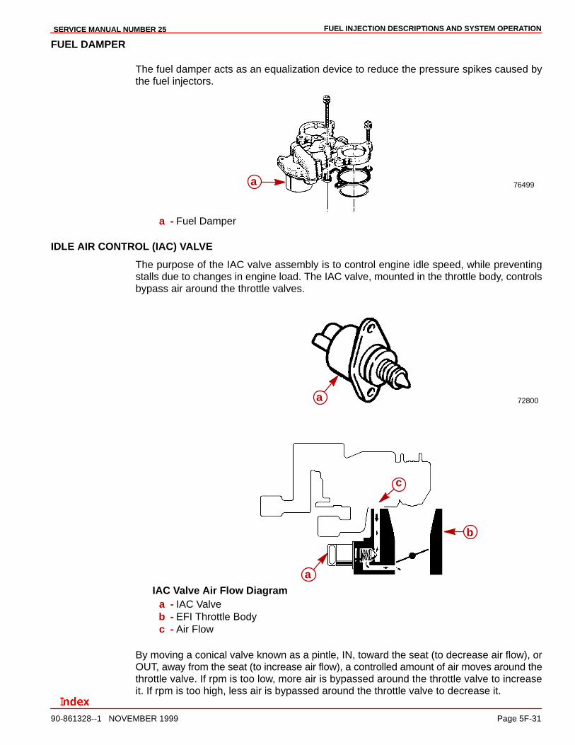
FUEL DAMPER
The fuel damper acts as an equalization device to reduce the pressure spikes caused bythe fuel injectors.
76499a
a - Fuel Damper
IDLE AIR CONTROL (IAC) VALVE
The purpose of the IAC valve assembly is to control engine idle speed, while preventingstalls due to changes in engine load. The IAC valve, mounted in the throttle body, controlsbypass air around the throttle valves.
72800a
b
c
aIAC Valve Air Flow Diagram
a - IAC Valveb - EFI Throttle Bodyc - Air Flow
By moving a conical valve known as a pintle, IN, toward the seat (to decrease air flow), orOUT, away from the seat (to increase air flow), a controlled amount of air moves around thethrottle valve. If rpm is too low, more air is bypassed around the throttle valve to increaseit. If rpm is too high, less air is bypassed around the throttle valve to decrease it.

FUEL INJECTION DESCRIPTIONS AND SYSTEM OPERATION SERVICE MANUAL NUMBER 25
Page 5F-32 90-861328--1 NOVEMBER 1999
The ECM moves the IAC valve in small steps, called counts. These can be measured byscan tool test equipment, which plugs into the DLC.
During idle, the proper position of the IAC valve is based on engine rpm. If the rpm dropsbelow specification and the throttle valve is closed, the ECM senses a near stall conditionand calculates a new valve position to prevent stalling.
• Engine idle speed is a function of total air flow into the engine based on IAC valve pintleposition + throttle valve stop screws and PCV.
• “Controlled” idle speed is programmed into the ECM, which determines the correct IACvalve pintle position to maintain the desired idle speed for all engine operating condi-tions and loads.
• The minimum idle air rate is set at the factory with stop screws. This setting allowsenough air flow by the throttle valves to cause the IAC valve pintle to be positioned acalibrated number of steps (counts) from the seat during “controlled” idle operation.
• If the IAC valve is disconnected and reconnected with the engine running, the idle speedmay be wrong. In this case, the IAC valve can be reset by doing the following: turn offengine, wait ten seconds, and restart engine.

FUEL INJECTION DESCRIPTIONS AND SYSTEM OPERATIONSERVICE MANUAL NUMBER 25
90-861328--1 NOVEMBER 1999 Page 5F-33
THIS PAGE IS INTENTIONALLY BLANK

FUEL INJECTION DESCRIPTIONS AND SYSTEM OPERATION SERVICE MANUAL NUMBER 25
Page 5F-34 90-861328--1 NOVEMBER 1999
THIS PAGE IS INTENTIONALLY BLANK