Embed Size (px)
Citation preview
ASFILE NO.
SERVICE MANUAL
(SUPPLEMENT)
Remote Control Color
TelevisionDS25204 (U.S.A.)
(CANADA)ORIGINAL VERSION
Chassis No. 25204-00
NOTE: Match the Chassis No. on the unit’s back cover with the Chassis No. in theService Manual.
If the Original Version
Service Manual Chassis
No. does not match the
unit’s, additional ServiceLiterature is required. Youmust refer to “Notices” tothe Original Service Manualprior to servicing the unit.
G7KTM, PRODUCT CODE 111372295 REFERENCE No. SS780047
THIS CHASSIS IS SIMILAR TO MODEL DS25320, CHASSIS NUMBER
25320-06. SERVICE INFORMATION GIVEN IN THIS MANUAL IS ONLY
THE DIFFERENCE INFORMATION FROM MODEL DS25320, CHASSIS
NUMBER 25320-06. FOR ADDITIONAL SERVICE INFORMATION, REFER
TO THE SERVICE MANUAL FOR CHASSIS NUMBER 25320-06 USED IN
MODEL DS25320 (SM780077-06).
AS
VIDEO IN L-AUDIO-R
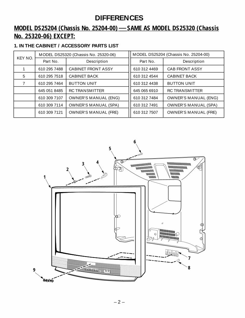
1 610 295 7488 CABINET FRONT ASSY 610 312 4469 CAB FRONT ASSY
5 610 295 7518 CABINET BACK 610 312 4544 CABINET BACK
7 610 295 7464 BUTTON UNIT 610 312 4438 BUTTON UNIT
645 051 8485 RC TRANSMITTER 645 065 6910 RC TRANSMITTER
610 309 7107 OWNER’S MANUAL (ENG) 610 312 7484 OWNER’S MANUAL (ENG)
610 309 7114 OWNER’S MANUAL (SPA) 610 312 7491 OWNER’S MANUAL (SPA)
610 309 7121 OWNER’S MANUAL (FRE) 610 312 7507 OWNER’S MANUAL (FRE)
DIFFERENCES
MODEL DS25204 (Chassis No. 25204-00) SAME AS MODEL DS25320 (ChassisNo. 25320-06) EXCEPT:1. IN THE CABINET / ACCESSORY PARTS LIST
MODEL DS25320 (Chassis No. 25320-06) MODEL DS25204 (Chassis No. 25204-00)
Part No. DescriptionKEY NO.
Part No. Description
56
7
9 8
1
432
AS
VIDEO IN L-AUDIO-R
– 2 –
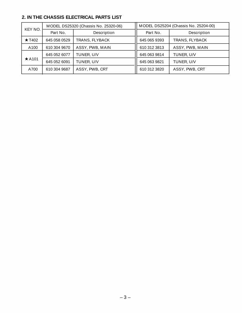
T402 645 058 0529 TRANS, FLYBACK 645 065 9393 TRANS, FLYBACK
A100 610 304 9670 ASSY, PWB, MAIN 610 312 3813 ASSY, PWB, MAIN
645 052 6077 TUNER, U/V 645 063 9814 TUNER, U/V A101
645 052 6091 TUNER, U/V 645 063 9821 TUNER, U/V
A700 610 304 9687 ASSY, PWB, CRT 610 312 3820 ASSY, PWB, CRT
2. IN THE CHASSIS ELECTRICAL PARTS LIST
MODEL DS25320 (Chassis No. 25320-06) MODEL DS25204 (Chassis No. 25204-00)
Part No. DescriptionKEY NO.
Part No. Description
– 3 –

March / 2004 / 2000 SMC Printed in U.S.A.
For parts or service contact
21605 Plummer Street
Chatsworth, CA 91311 (U.S.A.)
300 Applewood Crescent,
Concord, Ontario L4K 5C7 (CANADA)
SANYO FISHER SERVICE
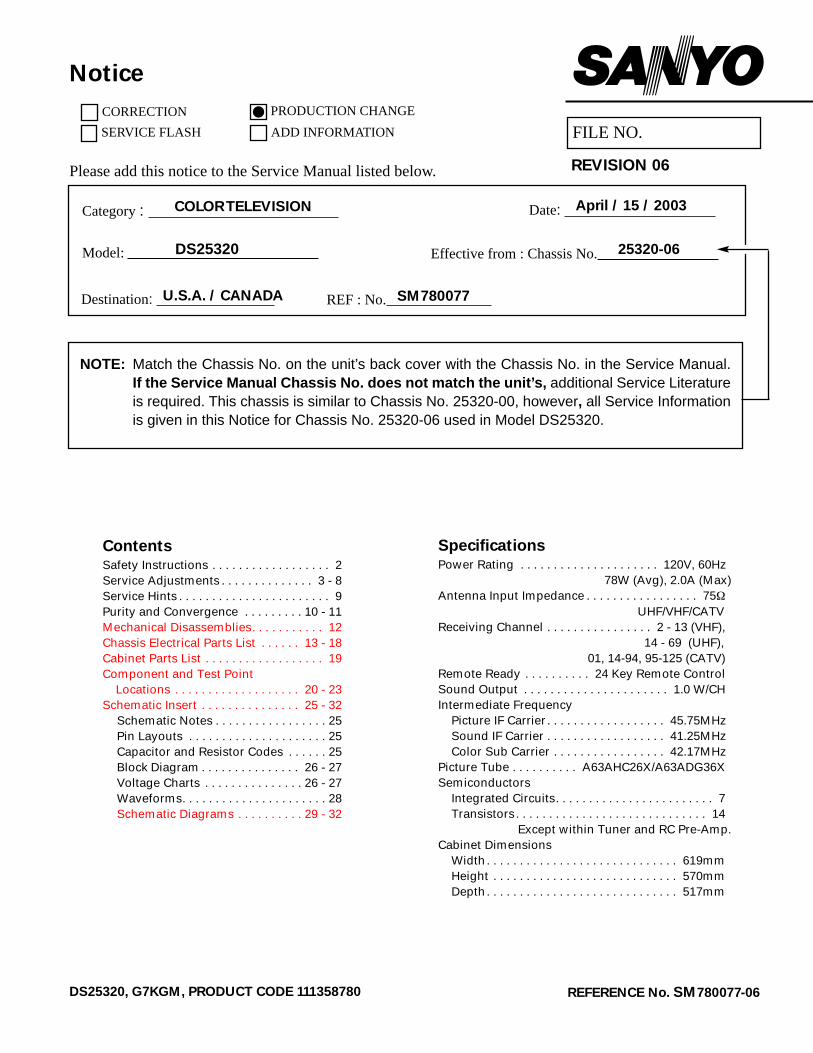
SpecificationsPower Rating . . . . . . . . . . . . . . . . . . . . . 120V, 60Hz
78W (Avg), 2.0A (Max)Antenna Input Impedance . . . . . . . . . . . . . . . . . 75Ω
UHF/VHF/CATVReceiving Channel . . . . . . . . . . . . . . . . 2 - 13 (VHF),
14 - 69 (UHF),01, 14-94, 95-125 (CATV)
Remote Ready . . . . . . . . . . 24 Key Remote ControlSound Output . . . . . . . . . . . . . . . . . . . . . . 1.0 W/CHIntermediate Frequency
Picture IF Carrier. . . . . . . . . . . . . . . . . . 45.75MHzSound IF Carrier . . . . . . . . . . . . . . . . . . 41.25MHzColor Sub Carrier . . . . . . . . . . . . . . . . . 42.17MHz
Picture Tube . . . . . . . . . . A63AHC26X/A63ADG36XSemiconductors
Integrated Circuits. . . . . . . . . . . . . . . . . . . . . . . . 7Transistors. . . . . . . . . . . . . . . . . . . . . . . . . . . . . 14
Except within Tuner and RC Pre-Amp.Cabinet Dimensions
Width. . . . . . . . . . . . . . . . . . . . . . . . . . . . . 619mmHeight . . . . . . . . . . . . . . . . . . . . . . . . . . . . 570mmDepth. . . . . . . . . . . . . . . . . . . . . . . . . . . . . 517mm
REFERENCE No. SM780077-06DS25320, G7KGM, PRODUCT CODE 111358780
AS
ContentsSafety Instructions . . . . . . . . . . . . . . . . . . 2Service Adjustments . . . . . . . . . . . . . . 3 - 8Service Hints . . . . . . . . . . . . . . . . . . . . . . . 9Purity and Convergence . . . . . . . . . 10 - 11Mechanical Disassemblies. . . . . . . . . . . 12Chassis Electrical Parts List . . . . . . 13 - 18Cabinet Parts List . . . . . . . . . . . . . . . . . . 19Component and Test Point
Locations . . . . . . . . . . . . . . . . . . . 20 - 23Schematic Insert . . . . . . . . . . . . . . . 25 - 32
Schematic Notes . . . . . . . . . . . . . . . . . 25Pin Layouts . . . . . . . . . . . . . . . . . . . . . 25Capacitor and Resistor Codes . . . . . . 25Block Diagram . . . . . . . . . . . . . . . 26 - 27Voltage Charts . . . . . . . . . . . . . . . 26 - 27Waveforms. . . . . . . . . . . . . . . . . . . . . . 28Schematic Diagrams . . . . . . . . . . 29 - 32
DS25320 Model:
COLOR TELEVISION
FILE NO.
Notice
CORRECTION
SERVICE FLASH
PRODUCTION CHANGE
ADD INFORMATION
Please add this notice to the Service Manual listed below. REVISION 06
Category :
U.S.A. / CANADADestination:
April / 15 / 2003Date:
25320-06Effective from : Chassis No.
SM780077REF : No.
NOTE: Match the Chassis No. on the unit’s back cover with the Chassis No. in the Service Manual.If the Service Manual Chassis No. does not match the unit’s, additional Service Literatureis required. This chassis is similar to Chassis No. 25320-00, however, all Service Informationis given in this Notice for Chassis No. 25320-06 used in Model DS25320.
— 2 —
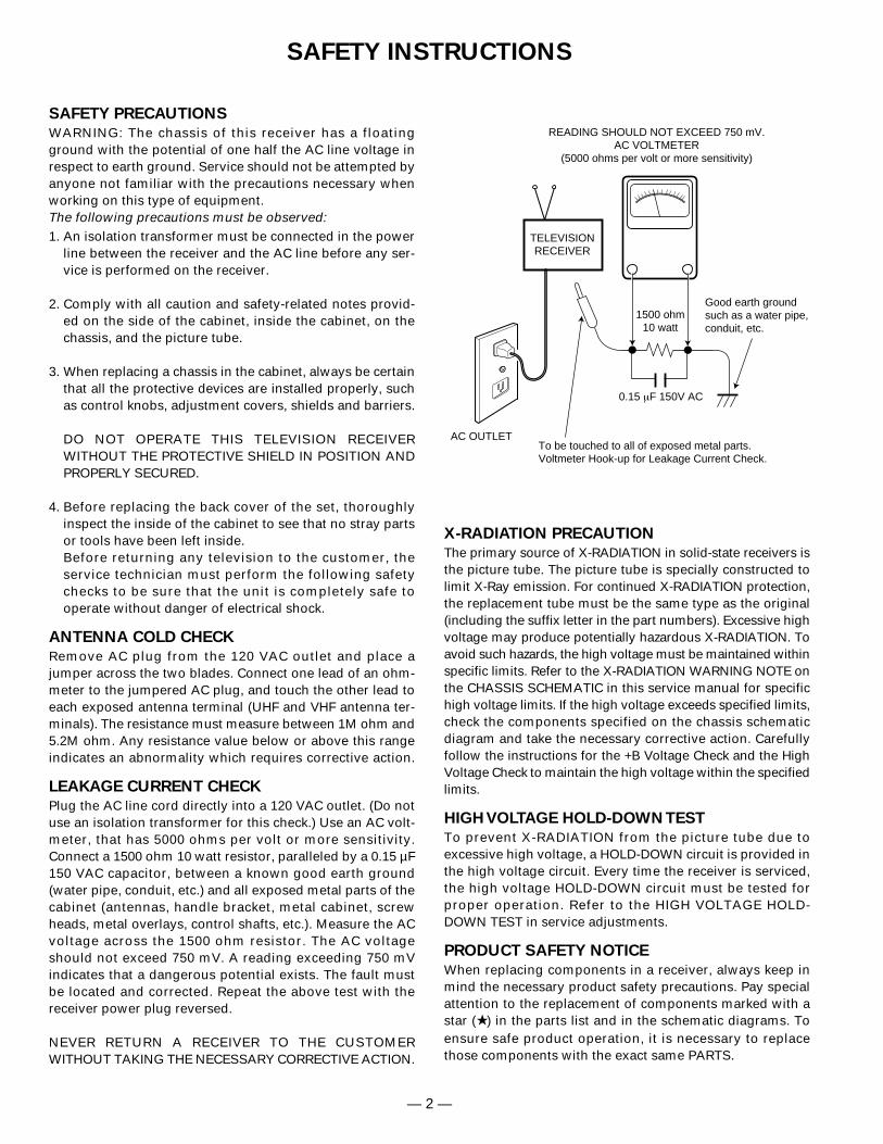
SAFETY PRECAUTIONS
WARNING: The chassis of this receiver has a floatingground with the potential of one half the AC line voltage inrespect to earth ground. Service should not be attempted byanyone not familiar with the precautions necessary whenworking on this type of equipment. The following precautions must be observed:1. An isolation transformer must be connected in the power
line between the receiver and the AC line before any ser-vice is performed on the receiver.
2. Comply with all caution and safety-related notes provid-ed on the side of the cabinet, inside the cabinet, on thechassis, and the picture tube.
3. When replacing a chassis in the cabinet, always be certainthat all the protective devices are installed properly, suchas control knobs, adjustment covers, shields and barriers.
DO NOT OPERATE THIS TELEVISION RECEIVER WITHOUT THE PROTECTIVE SHIELD IN POSITION ANDPROPERLY SECURED.
4. Before replacing the back cover of the set, thoroughlyinspect the inside of the cabinet to see that no stray partsor tools have been left inside.Before returning any television to the customer, the service technician must perform the following safetychecks to be sure that the unit is completely safe to operate without danger of electrical shock.
ANTENNA COLD CHECK
Remove AC plug from the 120 VAC outlet and place ajumper across the two blades. Connect one lead of an ohm-meter to the jumpered AC plug, and touch the other lead toeach exposed antenna terminal (UHF and VHF antenna ter-minals). The resistance must measure between 1M ohm and5.2M ohm. Any resistance value below or above this rangeindicates an abnormality which requires corrective action.
LEAKAGE CURRENT CHECK
Plug the AC line cord directly into a 120 VAC outlet. (Do notuse an isolation transformer for this check.) Use an AC volt-meter, that has 5000 ohms per volt or more sensitivity.Connect a 1500 ohm 10 watt resistor, paralleled by a 0.15 µF150 VAC capacitor, between a known good earth ground(water pipe, conduit, etc.) and all exposed metal parts of thecabinet (antennas, handle bracket, metal cabinet, screwheads, metal overlays, control shafts, etc.). Measure the ACvoltage across the 1500 ohm resistor. The AC voltageshould not exceed 750 mV. A reading exceeding 750 mVindicates that a dangerous potential exists. The fault mustbe located and corrected. Repeat the above test with thereceiver power plug reversed.
NEVER RETURN A RECEIVER TO THE CUSTOMER WITHOUT TAKING THE NECESSARY CORRECTIVE ACTION.
X-RADIATION PRECAUTION
The primary source of X-RADIATION in solid-state receivers isthe picture tube. The picture tube is specially constructed tolimit X-Ray emission. For continued X-RADIATION protection,the replacement tube must be the same type as the original(including the suffix letter in the part numbers). Excessive highvoltage may produce potentially hazardous X-RADIATION. Toavoid such hazards, the high voltage must be maintained withinspecific limits. Refer to the X-RADIATION WARNING NOTE onthe CHASSIS SCHEMATIC in this service manual for specifichigh voltage limits. If the high voltage exceeds specified limits,check the components specified on the chassis schematicdiagram and take the necessary corrective action. Carefullyfollow the instructions for the +B Voltage Check and the HighVoltage Check to maintain the high voltage within the specifiedlimits.
HIGH VOLTAGE HOLD-DOWN TEST
To prevent X-RADIATION from the picture tube due toexcessive high voltage, a HOLD-DOWN circuit is provided inthe high voltage circuit. Every time the receiver is serviced,the high voltage HOLD-DOWN circuit must be tested forproper operation. Refer to the HIGH VOLTAGE HOLD-DOWN TEST in service adjustments.
PRODUCT SAFETY NOTICE
When replacing components in a receiver, always keep inmind the necessary product safety precautions. Pay specialattention to the replacement of components marked with astar ( ) in the parts list and in the schematic diagrams. Toensure safe product operation, it is necessary to replacethose components with the exact same PARTS.
SAFETY INSTRUCTIONS
0.15 µF 150V AC
1500 ohm10 watt
Good earth groundsuch as a water pipe,conduit, etc.
AC OUTLET
TELEVISIONRECEIVER
READING SHOULD NOT EXCEED 750 mV.AC VOLTMETER
(5000 ohms per volt or more sensitivity)
To be touched to all of exposed metal parts.Voltmeter Hook-up for Leakage Current Check.
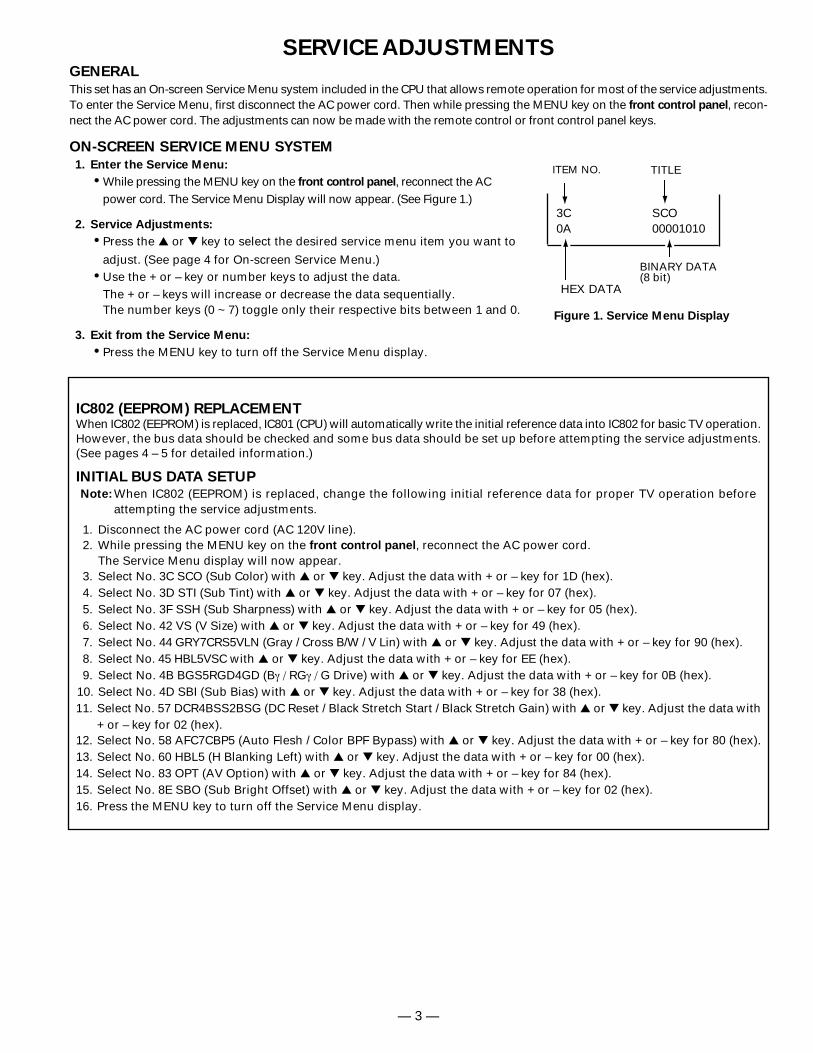
GENERAL
This set has an On-screen Service Menu system included in the CPU that allows remote operation for most of the service adjustments.To enter the Service Menu, first disconnect the AC power cord. Then while pressing the MENU key on the front control panel, recon-nect the AC power cord. The adjustments can now be made with the remote control or front control panel keys.
ON-SCREEN SERVICE MENU SYSTEM
1. Enter the Service Menu:
While pressing the MENU key on the front control panel, reconnect the ACpower cord. The Service Menu Display will now appear. (See Figure 1.)
2. Service Adjustments:
Press the or key to select the desired service menu item you want to
adjust. (See page 4 for On-screen Service Menu.) Use the + or – key or number keys to adjust the data.
The + or – keys will increase or decrease the data sequentially.The number keys (0 ~ 7) toggle only their respective bits between 1 and 0.
3. Exit from the Service Menu:
Press the MENU key to turn off the Service Menu display.
SERVICE ADJUSTMENTS
— 3 —
IC802 (EEPROM) REPLACEMENTWhen IC802 (EEPROM) is replaced, IC801 (CPU) will automatically write the initial reference data into IC802 for basic TV operation.However, the bus data should be checked and some bus data should be set up before attempting the service adjustments.(See pages 4 – 5 for detailed information.)
INITIAL BUS DATA SETUPNote: When IC802 (EEPROM) is replaced, change the following initial reference data for proper TV operation before
attempting the service adjustments.
1. Disconnect the AC power cord (AC 120V line).2. While pressing the MENU key on the front control panel, reconnect the AC power cord.
The Service Menu display will now appear.3. Select No. 3C SCO (Sub Color) with or key. Adjust the data with + or – key for 1D (hex).4. Select No. 3D STI (Sub Tint) with or key. Adjust the data with + or – key for 07 (hex).5. Select No. 3F SSH (Sub Sharpness) with or key. Adjust the data with + or – key for 05 (hex).6. Select No. 42 VS (V Size) with or key. Adjust the data with + or – key for 49 (hex).7. Select No. 44 GRY7CRS5VLN (Gray / Cross B/W / V Lin) with or key. Adjust the data with + or – key for 90 (hex).8. Select No. 45 HBL5VSC with or key. Adjust the data with + or – key for EE (hex).9. Select No. 4B BGS5RGD4GD (Bγ / RGγ / G Drive) with or key. Adjust the data with + or – key for 0B (hex).
10. Select No. 4D SBI (Sub Bias) with or key. Adjust the data with + or – key for 38 (hex).11. Select No. 57 DCR4BSS2BSG (DC Reset / Black Stretch Start / Black Stretch Gain) with or key. Adjust the data with
+ or – key for 02 (hex).12. Select No. 58 AFC7CBP5 (Auto Flesh / Color BPF Bypass) with or key. Adjust the data with + or – key for 80 (hex).13. Select No. 60 HBL5 (H Blanking Left) with or key. Adjust the data with + or – key for 00 (hex).14. Select No. 83 OPT (AV Option) with or key. Adjust the data with + or – key for 84 (hex).15. Select No. 8E SBO (Sub Bright Offset) with or key. Adjust the data with + or – key for 02 (hex).16. Press the MENU key to turn off the Service Menu display.
3C SCO0A 00001010
Figure 1. Service Menu Display
ITEM NO. TITLE
BINARY DATA(8 bit)
HEX DATA
— 4 —
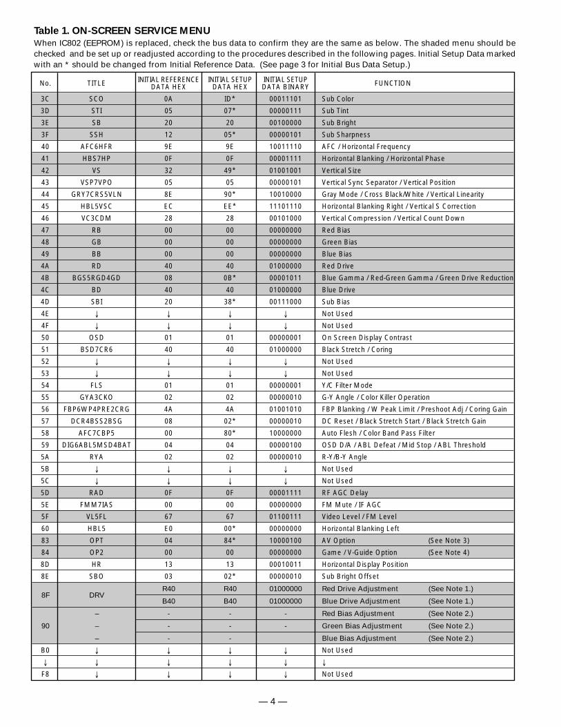
Table 1. ON-SCREEN SERVICE MENU
When IC802 (EEPROM) is replaced, check the bus data to confirm they are the same as below. The shaded menu should bechecked and be set up or readjusted according to the procedures described in the following pages. Initial Setup Data markedwith an * should be changed from Initial Reference Data. (See page 3 for Initial Bus Data Setup.)
No. TITLE INITIAL REFERENCE INITIAL SETUP INITIAL SETUP FUNCTIONDATA HEX DATA HEX DATA BINARY
3C SCO 0A ID* 00011101 Sub Color
3D STI 05 07* 00000111 Sub Tint
3E SB 20 20 00100000 Sub Bright
3F SSH 12 05* 00000101 Sub Sharpness
40 AFC6HFR 9E 9E 10011110 AFC / Horizontal Frequency
41 HBS7HP 0F 0F 00001111 Horizontal Blanking / Horizontal Phase
42 VS 32 49* 01001001 Vertical Size
43 VSP7VPO 05 05 00000101 Vertical Sync Separator / Vertical Position
44 GRY7CRS5VLN 8E 90* 10010000 Gray Mode / Cross Black/White / Vertical Linearity
45 HBL5VSC EC EE* 11101110 Horizontal Blanking Right / Vertical S Correction
46 VC3CDM 28 28 00101000 Vertical Compression / Vertical Count Down
47 RB 00 00 00000000 Red Bias
48 GB 00 00 00000000 Green Bias
49 BB 00 00 00000000 Blue Bias
4A RD 40 40 01000000 Red Drive
4B BGS5RGD4GD 08 0B* 00001011 Blue Gamma / Red-Green Gamma / Green Drive Reduction
4C BD 40 40 01000000 Blue Drive
4D SBI 20 38* 00111000 Sub Bias
4E ↓ ↓ ↓ ↓ Not Used
4F ↓ ↓ ↓ ↓ Not Used
50 OSD 01 01 00000001 On Screen Display Contrast
51 BSD7CR6 40 40 01000000 Black Stretch / Coring
52 ↓ ↓ ↓ ↓ Not Used
53 ↓ ↓ ↓ ↓ Not Used
54 FLS 01 01 00000001 Y/C Filter Mode
55 GYA3CKO 02 02 00000010 G-Y Angle / Color Killer Operation
56 FBP6WP4PRE2CRG 4A 4A 01001010 FBP Blanking / W Peak Limit / Preshoot Adj / Coring Gain
57 DCR4BSS2BSG 08 02* 00000010 DC Reset / Black Stretch Start / Black Stretch Gain
58 AFC7CBP5 00 80* 10000000 Auto Flesh / Color Band Pass Filter
59 DIG6ABL5MSD4BAT 04 04 00000100 OSD D/A / ABL Defeat / Mid Stop / ABL Threshold
5A RYA 02 02 00000010 R-Y/B-Y Angle
5B ↓ ↓ ↓ ↓ Not Used
5C ↓ ↓ ↓ ↓ Not Used
5D RAD 0F 0F 00001111 RF AGC Delay
5E FMM7IAS 00 00 00000000 FM Mute / IF AGC
5F VL5FL 67 67 01100111 Video Level / FM Level
60 HBL5 E0 00* 00000000 Horizontal Blanking Left
83 OPT 04 84* 10000100 AV Option (See Note 3)
84 OP2 00 00 00000000 Game / V-Guide Option (See Note 4)
8D HR 13 13 00010011 Horizontal Display Position
8E SBO 03 02* 00000010 Sub Bright Offset
8F DRVR40 R40 01000000 Red Drive Adjustment (See Note 1.)
B40 B40 01000000 Blue Drive Adjustment (See Note 1.)
– - - - Red Bias Adjustment (See Note 2.)
90 – - - - Green Bias Adjustment (See Note 2.)
– - - Blue Bias Adjustment (See Note 2.)
B0 ↓ ↓ ↓ ↓ Not Used
↓ ↓ ↓ ↓ ↓ ↓
F8 ↓ ↓ ↓ ↓ Not Used
— 5 —
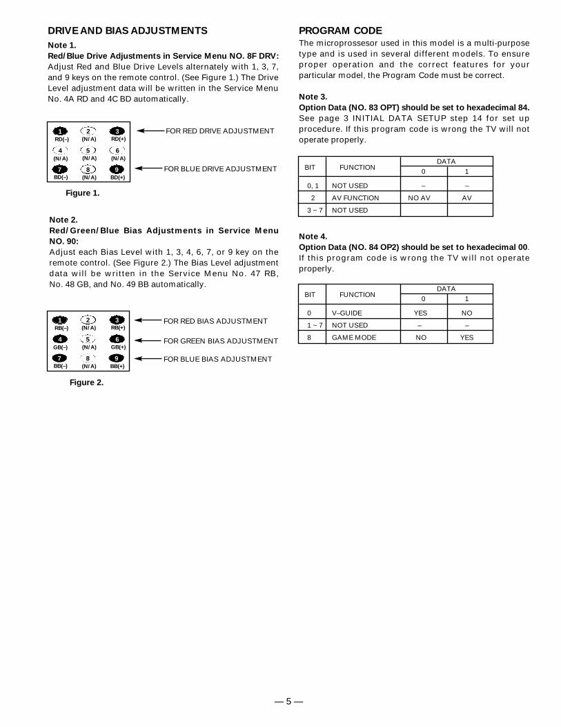
PROGRAM CODE
The microprossesor used in this model is a multi-purposetype and is used in several different models. To ensureproper operation and the correct features for your particular model, the Program Code must be correct.
Note 3.
Option Data (NO. 83 OPT) should be set to hexadecimal 84.
See page 3 INITIAL DATA SETUP step 14 for set up procedure. If this program code is wrong the TV will notoperate properly.
Note 4.
Option Data (NO. 84 OP2) should be set to hexadecimal 00.If this program code is wrong the TV will not operate properly.
Note 1.
Red/Blue Drive Adjustments in Service Menu NO. 8F DRV:
Adjust Red and Blue Drive Levels alternately with 1, 3, 7,and 9 keys on the remote control. (See Figure 1.) The DriveLevel adjustment data will be written in the Service MenuNo. 4A RD and 4C BD automatically.
1 2 3
4 5 6
7 98
RB(–) RB(+)
BB(–) BB(+)
(N/A)
GB(–) (N/A) GB(+)
(N/A)
FOR RED BIAS ADJUSTMENT
FOR BLUE BIAS ADJUSTMENT
FOR GREEN BIAS ADJUSTMENT
Figure 1.
Figure 2.
1 2 3
4 5 6
7 98
RD(–) RD(+)
BD(–) BD(+)
(N/A)
(N/A) (N/A) (N/A)
(N/A)
FOR RED DRIVE ADJUSTMENT
FOR BLUE DRIVE ADJUSTMENT
Note 2.
Red/Green/Blue Bias Adjustments in Service Menu
NO. 90:
Adjust each Bias Level with 1, 3, 4, 6, 7, or 9 key on theremote control. (See Figure 2.) The Bias Level adjustmentdata will be written in the Service Menu No. 47 RB, No. 48 GB, and No. 49 BB automatically.
BIT FUNCTIONDATA
0 1
0, 1 NOT USED – –
2 AV FUNCTION NO AV AV
3 ~ 7 NOT USED
DRIVE AND BIAS ADJUSTMENTS
BIT FUNCTIONDATA
0 1
0 V–GUIDE YES NO
1 ~ 7 NOT USED – –
8 GAME MODE NO YES
SERVICE ADJUSTMENTS (Continued)
— 6 —
ANTENNA CONNECTIONS
This receiver is designed for UHF/VHF reception. A 75 ohm terminal is provided for UHF and VHF receptions. Whenconnecting a CATV antenna system, connect the 75 ohmcoaxial cable directly to the 75 ohm terminal. For 300 ohmVHF antenna, use an adapter (not included with the TV set).
CIRCUIT PROTECTION
Fuse F601 (4A) is included in the AC line. This fuse must bereplaced with the proper fuse (see Parts List).
+B VOLTAGE CHECK
Connect Voltmeter + lead to TJ1 130V and – lead to ground(TE7). Connect receiver to AC 120V line. Tune receiver to anactive channel. Reset the picture controls to the AUTOlevel. Voltage must measure between +128.0V and +132.0V.If the voltage is out of this range, the power circuit must bechecked. No +B adjustment is provided on this chassis.
HORIZONTAL CENTERING ADJUSTMENT
1. Tune receiver to an active channel.2. Check that picture is in the horizontal center of TV screen. If
picture is not centered horizontally, perform steps 3 ~ 6.3. Turn off the receiver and disconnect the AC power cord
(120V AC line).4. While pressing the MENU key, reconnect the AC power
cord. The Service Menu display will now appear.5. Select NO. 41 HPS7HP (Horiz. Phase) with or key.6. Adjust the data with + or – key for horizontal center. To
turn off the Service Menu display, press the MENU key.
VERTICAL SIZE ADJUSTMENT
1. Tune receiver to an active channel.2. Check the vertical size of the picture. If the vertical size is
too large or small, perform steps 3 ~ 6.3. Turn off the receiver and disconnect the AC power cord
(120V AC line).4. While pressing the MENU key, reconnect the AC power
cord. The Service Menu display will now appear.5. Select NO. 42 VS (Vertical Size) with or key.6. Adjust the data with + or – key for full scan. To turn off
the Service Menu display, press the MENU key.
VERTICAL CENTERING ADJUSTMENT
1. Tune receiver to an active channel.2. Check that picture is in the center of TV screen. If picture
center is too low, add resistor R513 (470 ohm, 1W). If picturecenter is too high, add resistor R512 (470 ohm, 1W).
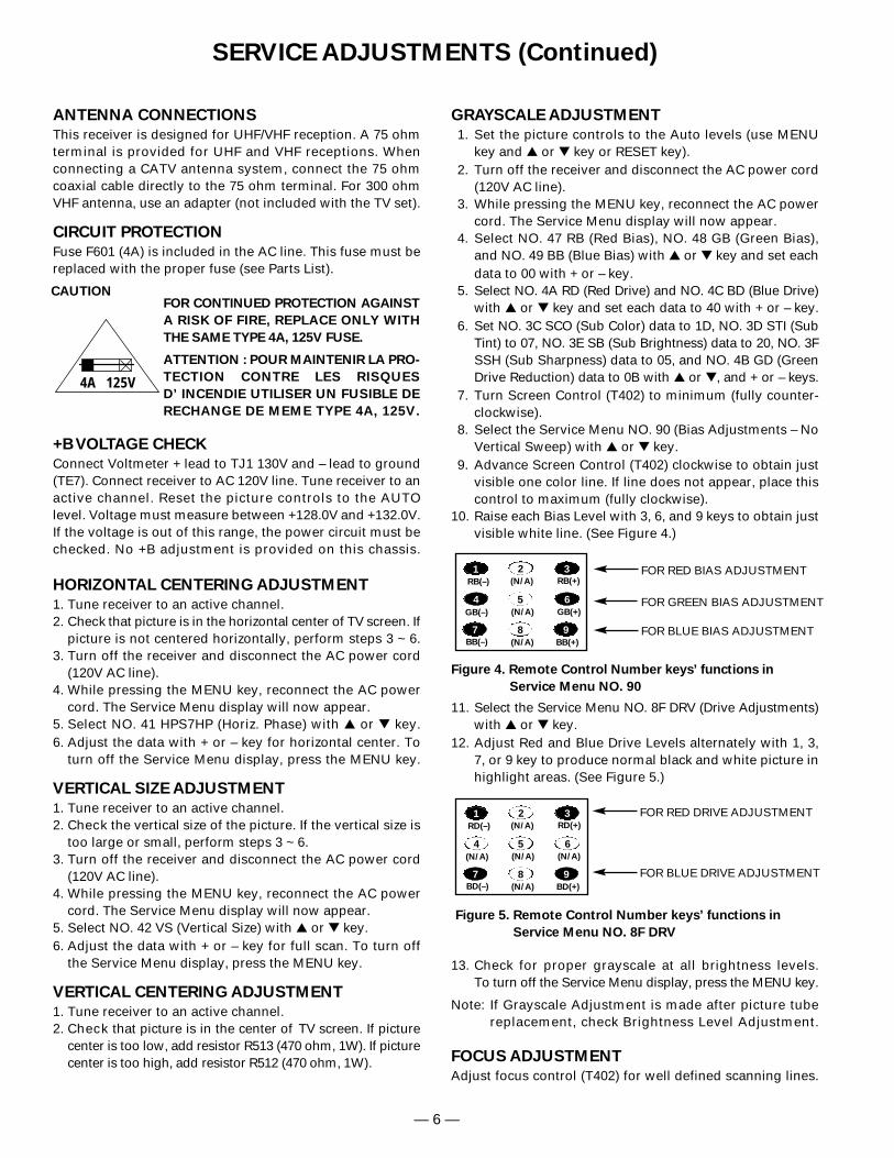
GRAYSCALE ADJUSTMENT
1. Set the picture controls to the Auto levels (use MENUkey and or key or RESET key).
2. Turn off the receiver and disconnect the AC power cord(120V AC line).
3. While pressing the MENU key, reconnect the AC powercord. The Service Menu display will now appear.
4. Select NO. 47 RB (Red Bias), NO. 48 GB (Green Bias),and NO. 49 BB (Blue Bias) with or key and set eachdata to 00 with + or – key.
5. Select NO. 4A RD (Red Drive) and NO. 4C BD (Blue Drive)with or key and set each data to 40 with + or – key.
6. Set NO. 3C SCO (Sub Color) data to 1D, NO. 3D STI (SubTint) to 07, NO. 3E SB (Sub Brightness) data to 20, NO. 3FSSH (Sub Sharpness) data to 05, and NO. 4B GD (GreenDrive Reduction) data to 0B with or , and + or – keys.
7. Turn Screen Control (T402) to minimum (fully counter-clockwise).
8. Select the Service Menu NO. 90 (Bias Adjustments – NoVertical Sweep) with or key.
9. Advance Screen Control (T402) clockwise to obtain justvisible one color line. If line does not appear, place thiscontrol to maximum (fully clockwise).
10. Raise each Bias Level with 3, 6, and 9 keys to obtain just visible white line. (See Figure 4.)
11. Select the Service Menu NO. 8F DRV (Drive Adjustments)with or key.
12. Adjust Red and Blue Drive Levels alternately with 1, 3,7, or 9 key to produce normal black and white picture inhighlight areas. (See Figure 5.)
13. Check for proper grayscale at all brightness levels.To turn off the Service Menu display, press the MENU key.
Note: If Grayscale Adjustment is made after picture tubereplacement, check Brightness Level Adjustment.
FOCUS ADJUSTMENT
Adjust focus control (T402) for well defined scanning lines.
CAUTIONFOR CONTINUED PROTECTION AGAINST
A RISK OF FIRE, REPLACE ONLY WITH
THE SAME TYPE 4A, 125V FUSE.
ATTENTION : POUR MAINTENIR LA PRO-
TECTION CONTRE LES RISQUES
D’ INCENDIE UTILISER UN FUSIBLE DE
RECHANGE DE MEME TYPE 4A, 125V.
4A 125V
1 2 3
4 5 6
7 98
RB(–) RB(+)
BB(–) BB(+)
(N/A)
GB(–) (N/A) GB(+)
(N/A)
FOR RED BIAS ADJUSTMENT
FOR BLUE BIAS ADJUSTMENT
FOR GREEN BIAS ADJUSTMENT
Figure 4. Remote Control Number keys’ functions in
Service Menu NO. 90
1 2 3
4 5 6
7 98
RD(–) RD(+)
BD(–) BD(+)
(N/A)
(N/A) (N/A) (N/A)
(N/A)
Figure 5. Remote Control Number keys’ functions in
Service Menu NO. 8F DRV
FOR RED DRIVE ADJUSTMENT
FOR BLUE DRIVE ADJUSTMENT
— 7 —
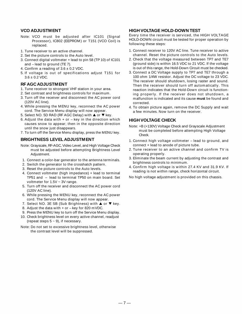
VCO ADJUSTMENT
Note: VCO must be adjusted after IC101 (SignalProcessor), IC802 (EEPROM) or T151 (VCO Coil) isreplaced.
1. Tune receiver to an active channel.2. Set the picture controls to the Auto level.3. Connect digital voltmeter + lead to pin 58 (TP 10) of IC101
and – lead to ground (TE 7).4. Confirm a reading of 3.6 ± 0.2 VDC.5. If voltage is out of specifications adjust T151 for
3.6 ± 0.2 VDC.
RF AGC ADJUSTMENT1. Tune receiver to strongest VHF station in your area.2. Set contrast and brightness controls for maximum.3. Turn off the receiver and disconnect the AC power cord
(120V AC line).4. While pressing the MENU key, reconnect the AC power
cord. The Service Menu display will now appear.5. Select NO. 5D RAD (RF AGC Delay) with or key.6. Adjust the data with + or – key in the direction which
causes snow to appear; then in the opposite directionuntil the snow just disappears.
7. To turn off the Service Menu display, press the MENU key.
BRIGHTNESS LEVEL ADJUSTMENT
Note: Grayscale, RF-AGC, Video Level, and High Voltage Checkmust be adjusted before attempting Brightness LevelAdjustment.
1. Connect a color-bar generator to the antenna terminals.2. Switch the generator to the crosshatch pattern.3. Reset the picture controls to the Auto levels.4. Connect voltmeter (high impedance) + lead to terminal
TP51 and – lead to terminal TP50 on main board. Setvoltmeter for 1.5V ~ 3V range.
5. Turn off the receiver and disconnect the AC power cord(120V AC line).
6. While pressing the MENU key, reconnect the AC powercord. The Service Menu display will now appear.
7. Select NO. 3E SB (Sub Brightness) with or key.8. Adjust the data with + or – key for 820 mVDC.9. Press the MENU key to turn off the Service Menu display.
10. Check brightness level on every active channel, readjust(repeat steps 5 ~ 9), if necessary.
Note: Do not set to excessive brightness level, otherwisethe contrast level will be suppressed.
HIGH VOLTAGE HOLD-DOWN TESTEvery time the receiver is serviced, the HIGH VOLTAGE HOLD-DOWN circuit must be tested for proper operation by following these steps:
1. Connect receiver to 120V AC line. Tune receiver to activechannel. Reset the picture controls to the Auto levels.
2. Check that the voltage measured between TP7 and TE7(ground side) is within 16.5 VDC to 21 VDC. If the voltageis out of this range, the Hold-Down Circuit must be checked.
3. Connect a DC Voltage supply to TP7 and TE7 through a100 ohm 1/4W resistor. Adjust the DC voltage to 23 VDC.The receiver should shutdown, losing raster and sound.Then the receiver should turn off automatically. Thisreaction indicates that the Hold-Down circuit is function-ing properly. If the receiver does not shutdown, amalfunction is indicated and its cause must be found andcorrected.
4. To obtain picture again, remove the DC Supply and waita few minutes. Now turn on the receiver.
HIGH VOLTAGE CHECK
Note: +B (+130V) Voltage Check and Grayscale Adjustmentmust be completed before attempting High VoltageCheck.
1. Connect high voltage voltmeter – lead to ground, andconnect + lead to anode of picture tube.
2. Tune receiver to an active channel and confirm TV isoperating properly.
3. Eliminate the beam current by adjusting the contrast andbrightness controls to minimum.
4. Confirm high voltage is within 27.4 KV and 31.9 KV. Ifreading is not within range, check horizontal circuit.
No high voltage adjustment is provided on this chassis.
— 8 —
SERVICE ADJUSTMENTS (Continued)
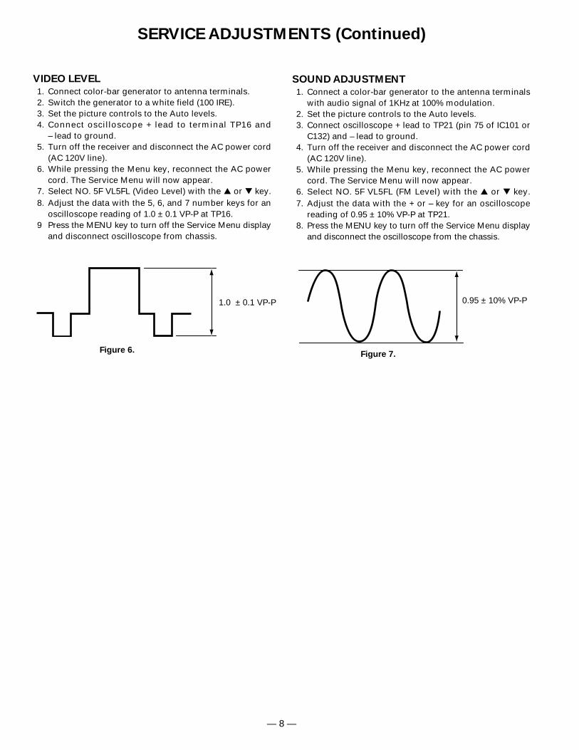
VIDEO LEVEL
1. Connect color-bar generator to antenna terminals.2. Switch the generator to a white field (100 IRE).3. Set the picture controls to the Auto levels.4. Connect oscilloscope + lead to terminal TP16 and
– lead to ground.5. Turn off the receiver and disconnect the AC power cord
(AC 120V line).6. While pressing the Menu key, reconnect the AC power
cord. The Service Menu will now appear.7. Select NO. 5F VL5FL (Video Level) with the or key.8. Adjust the data with the 5, 6, and 7 number keys for an
oscilloscope reading of 1.0 ± 0.1 VP-P at TP16.9 Press the MENU key to turn off the Service Menu display
and disconnect oscilloscope from chassis.
SOUND ADJUSTMENT
1. Connect a color-bar generator to the antenna terminalswith audio signal of 1KHz at 100% modulation.
2. Set the picture controls to the Auto levels.3. Connect oscilloscope + lead to TP21 (pin 75 of IC101 or
C132) and – lead to ground. 4. Turn off the receiver and disconnect the AC power cord
(AC 120V line).5. While pressing the Menu key, reconnect the AC power
cord. The Service Menu will now appear.6. Select NO. 5F VL5FL (FM Level) with the or key.7. Adjust the data with the + or – key for an oscilloscope
reading of 0.95 ± 10% VP-P at TP21.8. Press the MENU key to turn off the Service Menu display
and disconnect the oscilloscope from the chassis.
Figure 6.Figure 7.
1.0 ± 0.1 VP-P 0.95 ± 10% VP-P
— 9 —
SERVICE HINTS
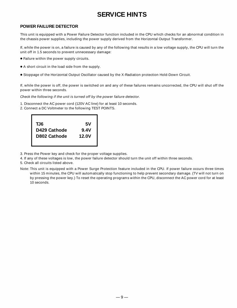
POWER FAILURE DETECTOR
This unit is equipped with a Power Failure Detector function included in the CPU which checks for an abnormal condition inthe chassis power supplies, including the power supply derived from the Horizontal Output Transformer.
If, while the power is on, a failure is caused by any of the following that results in a low voltage supply, the CPU will turn theunit off in 1.5 seconds to prevent unnecessary damage:
• Failure within the power supply circuits.
• A short circuit in the load side from the supply.
• Stoppage of the Horizontal Output Oscillator caused by the X-Radiation protection Hold-Down Circuit.
If, while the power is off, the power is switched on and any of these failures remains uncorrected, the CPU will shut off thepower within three seconds.
Check the following if the unit is turned off by the power failure detector.
1. Disconnect the AC power cord (120V AC line) for at least 10 seconds.2. Connect a DC Voltmeter to the following TEST POINTS.
3. Press the Power key and check for the proper voltage supplies.4. If any of these voltages is low, the power failure detector should turn the unit off within three seconds.5. Check all circuits listed above.
Note: This unit is equipped with a Power Surge Protection feature included in the CPU. If power failure occurs three timeswithin 15 minutes, the CPU will automatically stop functioning to help prevent secondary damage. (TV will not turn onby pressing the power key.) To reset the operating programs within the CPU, disconnect the AC power cord for at least10 seconds.
TJ6 5V
D429 Cathode 9.4V
D802 Cathode 12.0V
— 10 —
MAGNET TABS
ANGLE OF MAGNET TABS
SIX-POLEMAGNET TABS FOUR-POLE
MAGNET TABS
ANGLEOF TABS
PURITYMAGNETTABS
43
21
FOCUS GAP(G3-G4)
Figure 3. Adjusting Magnet
Figure 2. Purity and Convergence Magnets
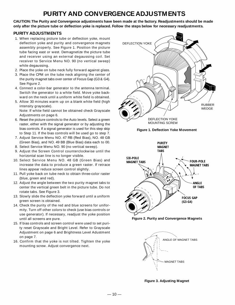
PURITY ADJUSTMENTS
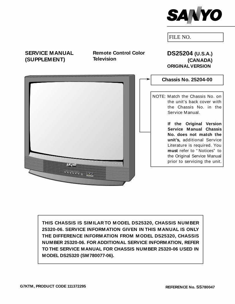
1. When replacing picture tube or deflection yoke, mountdeflection yoke and purity and convergence magnetsassembly properly. See Figure 1. Position the picturetube facing east or west. Demagnetize the picture tubeand receiver using an external degaussing coil. Setreceiver to Service Menu NO. 90 (no vertical sweep)while degaussing.
2. Place the yoke on tube neck fully forward against glass.3. Place the CPM on the tube neck aligning the center of
the purity magnet tabs over center of Focus Gap (G3 & G4).See Figure 2.
4. Connect a color-bar generator to the antenna terminal.Switch the generator to a white field. Move yoke back-ward on the neck until a uniform white field is obtained.
5. Allow 30 minutes warm up on a blank white field (highintensity grayscale).Note: If white field cannot be obtained check GrayscaleAdjustments on page 6.
6. Reset the picture controls to the Auto levels. Select a greenraster, either with the signal generator or by adjusting thebias controls. If a signal generator is used for this step skipto Step 11. If the bias controls will be used go to step 7.
7. Adjust Service Menu NO. 47 RB (Red Bias), NO. 48 GB(Green Bias), and NO. 49 BB (Blue Bias) data each to 00.
8. Select Service Menu NO. 90 (no vertical sweep).9. Adjust the Screen Control counterclockwise until the
horizontal scan line is no longer visible.10. Select Service Menu NO. 48 GB (Green Bias) and
increase the data to produce a green raster. If retracelines appear reduce screen control slightly.
11. Pull yoke back on tube neck to obtain three-color raster(blue, green and red).
12. Adjust the angle between the two purity magnet tabs to center the vertical green belt in the picture tube. Do notrotate tabs. See Figure 3.
13. Slowly slide the deflection yoke forward until a uniformgreen screen is obtained.
14. Check the purity of the red and blue screens for unifor-mity. Turn off other colors to check (use bias controls oruse generator). If necessary, readjust the yoke positionuntil all screens are pure.
15. If bias controls and screen control were used to set puri-ty reset Grayscale and Bright Level. Refer to GrayscaleAdjustment on page 6 and Brightness Level Adustmenton page 7.
16. Confirm that the yoke is not tilted. Tighten the yokemounting screw. Adjust convergence next.
RUBBERWEDGE
DEFLECTION YOKE
DEFLECTION YOKEMOUNTING SCREW
Figure 1. Deflection Yoke Movement
PURITY AND CONVERGENCE ADJUSTMENTSCAUTION:The Purity and Convergence adjustments have been made at the factory. Readjustments should be made
only after the picture tube or deflection yoke is replaced. Follow the steps below for necessary readjustments.
— 11 —
BLUEGREEN
RED
BLUEGREENRED
BLUEGREEN
RED
BLUEGREEN
RED
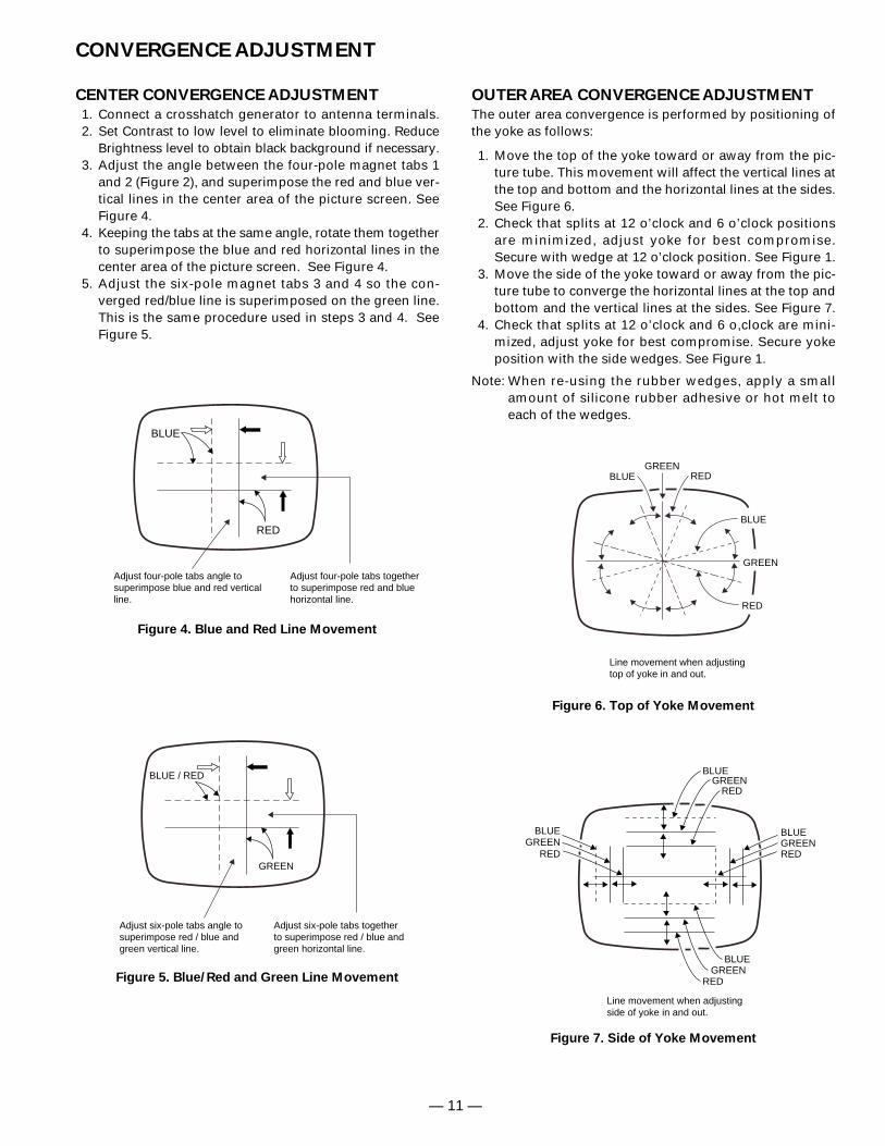
Line movement when adjustingside of yoke in and out.
CENTER CONVERGENCE ADJUSTMENT
1. Connect a crosshatch generator to antenna terminals.2. Set Contrast to low level to eliminate blooming. Reduce
Brightness level to obtain black background if necessary.3. Adjust the angle between the four-pole magnet tabs 1
and 2 (Figure 2), and superimpose the red and blue ver-tical lines in the center area of the picture screen. SeeFigure 4.
4. Keeping the tabs at the same angle, rotate them togetherto superimpose the blue and red horizontal lines in thecenter area of the picture screen. See Figure 4.
5. Adjust the six-pole magnet tabs 3 and 4 so the con-verged red/blue line is superimposed on the green line.This is the same procedure used in steps 3 and 4. SeeFigure 5.
CONVERGENCE ADJUSTMENT
BLUE
RED
Adjust four-pole tabs angle tosuperimpose blue and red verticalline.
Adjust four-pole tabs together to superimpose red and bluehorizontal line.
Figure 4. Blue and Red Line Movement
BLUE / RED
GREEN
Adjust six-pole tabs angle tosuperimpose red / blue andgreen vertical line.
Adjust six-pole tabs together to superimpose red / blue andgreen horizontal line.
REDGREEN
BLUE
RED
GREEN
BLUE
Line movement when adjustingtop of yoke in and out.
Figure 7. Side of Yoke Movement
OUTER AREA CONVERGENCE ADJUSTMENT
The outer area convergence is performed by positioning ofthe yoke as follows:
1. Move the top of the yoke toward or away from the pic-ture tube. This movement will affect the vertical lines atthe top and bottom and the horizontal lines at the sides.See Figure 6.
2. Check that splits at 12 o’clock and 6 o’clock positionsare minimized, adjust yoke for best compromise.Secure with wedge at 12 o’clock position. See Figure 1.
3. Move the side of the yoke toward or away from the pic-ture tube to converge the horizontal lines at the top andbottom and the vertical lines at the sides. See Figure 7.
4. Check that splits at 12 o’clock and 6 o,clock are mini-mized, adjust yoke for best compromise. Secure yokeposition with the side wedges. See Figure 1.
Note: When re-using the rubber wedges, apply a smallamount of silicone rubber adhesive or hot melt toeach of the wedges.
Figure 6. Top of Yoke Movement
Figure 5. Blue/Red and Green Line Movement
— 12 —
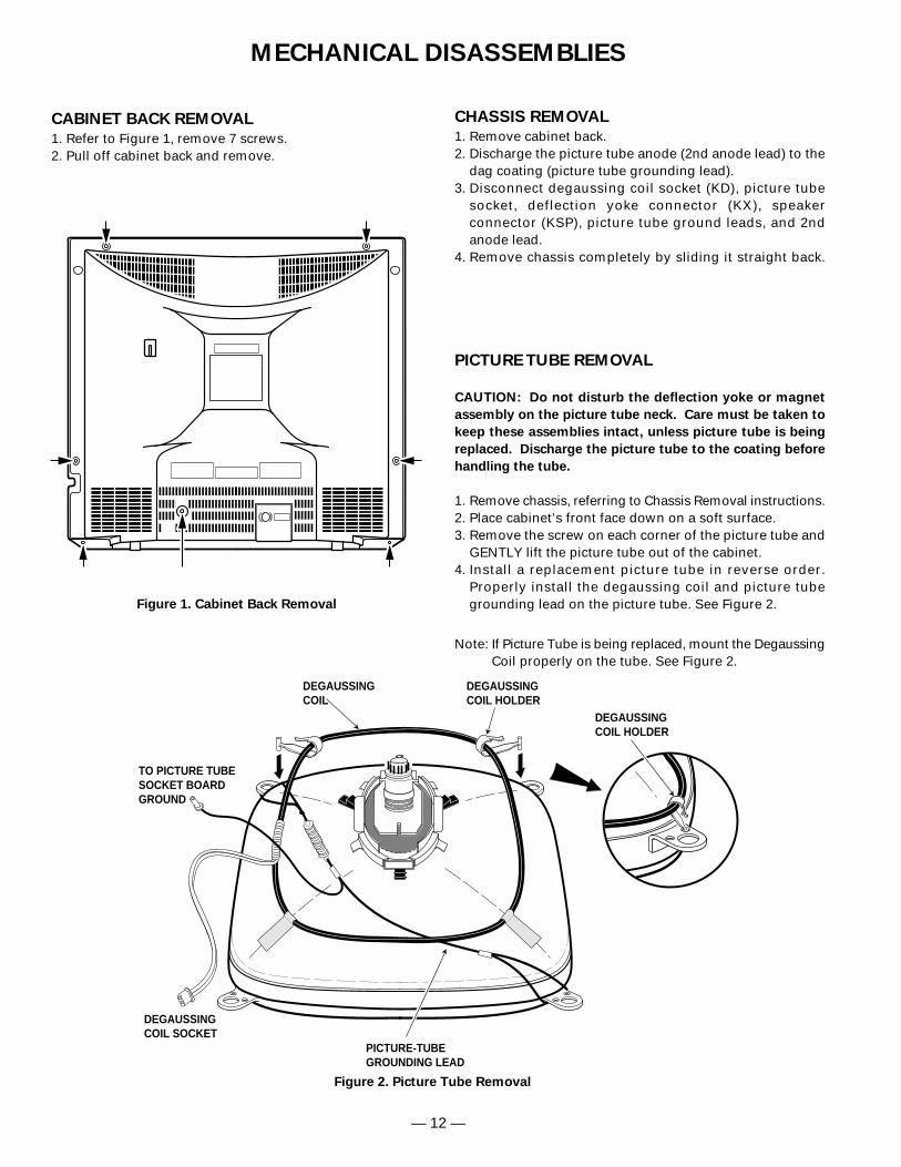
MECHANICAL DISASSEMBLIES
CABINET BACK REMOVAL
1. Refer to Figure 1, remove 7 screws.2. Pull off cabinet back and remove.
CHASSIS REMOVAL
1. Remove cabinet back.2. Discharge the picture tube anode (2nd anode lead) to the
dag coating (picture tube grounding lead).3. Disconnect degaussing coil socket (KD), picture tube
socket, deflection yoke connector (KX), speaker connector (KSP), picture tube ground leads, and 2ndanode lead.
4. Remove chassis completely by sliding it straight back.
Figure 1. Cabinet Back Removal
PICTURE TUBE REMOVAL
CAUTION: Do not disturb the deflection yoke or magnet
assembly on the picture tube neck. Care must be taken to
keep these assemblies intact, unless picture tube is being
replaced. Discharge the picture tube to the coating before
handling the tube.
1. Remove chassis, referring to Chassis Removal instructions.2. Place cabinet’s front face down on a soft surface.3. Remove the screw on each corner of the picture tube and
GENTLY lift the picture tube out of the cabinet.4. Install a replacement picture tube in reverse order.
Properly install the degaussing coil and picture tubegrounding lead on the picture tube. See Figure 2.
Note: If Picture Tube is being replaced, mount the DegaussingCoil properly on the tube. See Figure 2.
Figure 2. Picture Tube Removal
DEGAUSSINGCOIL
DEGAUSSINGCOIL HOLDER
PICTURE-TUBEGROUNDING LEAD
TO PICTURE TUBESOCKET BOARDGROUND
DEGAUSSING COIL SOCKET
DEGAUSSINGCOIL HOLDER
— 13 —
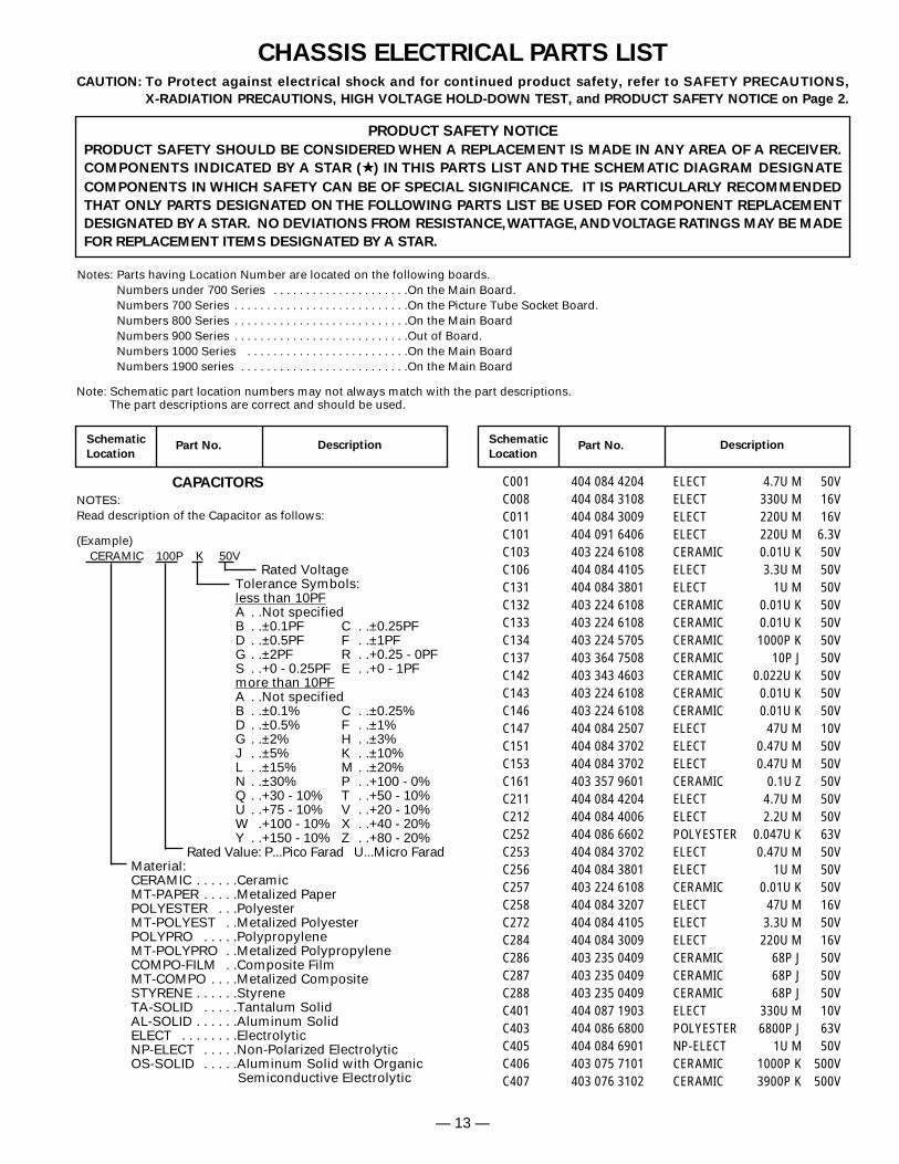
CHASSIS ELECTRICAL PARTS LISTCAUTION: To Protect against electrical shock and for continued product safety, refer to SAFETY PRECAUTIONS,
X-RADIATION PRECAUTIONS, HIGH VOLTAGE HOLD-DOWN TEST, and PRODUCT SAFETY NOTICE on Page 2.
Notes: Parts having Location Number are located on the following boards.Numbers under 700 Series . . . . . . . . . . . . . . . . . . . . .On the Main Board.Numbers 700 Series . . . . . . . . . . . . . . . . . . . . . . . . . . .On the Picture Tube Socket Board.Numbers 800 Series . . . . . . . . . . . . . . . . . . . . . . . . . . .On the Main BoardNumbers 900 Series . . . . . . . . . . . . . . . . . . . . . . . . . . .Out of Board.Numbers 1000 Series . . . . . . . . . . . . . . . . . . . . . . . . .On the Main BoardNumbers 1900 series . . . . . . . . . . . . . . . . . . . . . . . . . .On the Main Board
PRODUCT SAFETY NOTICE
PRODUCT SAFETY SHOULD BE CONSIDERED WHEN A REPLACEMENT IS MADE IN ANY AREA OF A RECEIVER.
COMPONENTS INDICATED BY A STAR ( ) IN THIS PARTS LIST AND THE SCHEMATIC DIAGRAM DESIGNATE
COMPONENTS IN WHICH SAFETY CAN BE OF SPECIAL SIGNIFICANCE. IT IS PARTICULARLY RECOMMENDED
THAT ONLY PARTS DESIGNATED ON THE FOLLOWING PARTS LIST BE USED FOR COMPONENT REPLACEMENT
DESIGNATED BY A STAR. NO DEVIATIONS FROM RESISTANCE,WATTAGE, AND VOLTAGE RATINGS MAY BE MADE
FOR REPLACEMENT ITEMS DESIGNATED BY A STAR.
Schematic
LocationPart No. Description
Schematic
LocationPart No. Description
Note: Schematic part location numbers may not always match with the part descriptions.The part descriptions are correct and should be used.
CAPACITORS
NOTES:Read description of the Capacitor as follows:
(Example)CERAMIC 100P K 50V
Rated VoltageTolerance Symbols:less than 10PFA . .Not specifiedB . .±0.1PF C . .±0.25PFD . .±0.5PF F . .±1PFG . .±2PF R . .+0.25 - 0PFS . .+0 - 0.25PF E . .+0 - 1PFmore than 10PFA . .Not specifiedB . .±0.1% C . .±0.25%D . .±0.5% F . .±1%G . .±2% H . .±3%J . .±5% K . .±10%L . .±15% M . .±20%N . .±30% P . .+100 - 0%Q . .+30 - 10% T . .+50 - 10%U . .+75 - 10% V . .+20 - 10%W .+100 - 10% X . .+40 - 20%Y . .+150 - 10% Z . .+80 - 20%
Rated Value: P...Pico Farad U...Micro FaradMaterial:CERAMIC . . . . . .CeramicMT-PAPER . . . . .Metalized PaperPOLYESTER . . .PolyesterMT-POLYEST . .Metalized PolyesterPOLYPRO . . . . .PolypropyleneMT-POLYPRO . .Metalized PolypropyleneCOMPO-FILM . .Composite FilmMT-COMPO . . . .Metalized CompositeSTYRENE . . . . . .StyreneTA-SOLID . . . . .Tantalum SolidAL-SOLID . . . . . .Aluminum SolidELECT . . . . . . . .ElectrolyticNP-ELECT . . . . .Non-Polarized ElectrolyticOS-SOLID . . . . .Aluminum Solid with Organic
Semiconductive Electrolytic
C001 404 084 4204 ELECT 4.7U M 50VC008 404 084 3108 ELECT 330U M 16VC011 404 084 3009 ELECT 220U M 16VC101 404 091 6406 ELECT 220U M 6.3VC103 403 224 6108 CERAMIC 0.01U K 50VC106 404 084 4105 ELECT 3.3U M 50VC131 404 084 3801 ELECT 1U M 50VC132 403 224 6108 CERAMIC 0.01U K 50VC133 403 224 6108 CERAMIC 0.01U K 50VC134 403 224 5705 CERAMIC 1000P K 50VC137 403 364 7508 CERAMIC 10P J 50VC142 403 343 4603 CERAMIC 0.022U K 50VC143 403 224 6108 CERAMIC 0.01U K 50VC146 403 224 6108 CERAMIC 0.01U K 50VC147 404 084 2507 ELECT 47U M 10VC151 404 084 3702 ELECT 0.47U M 50VC153 404 084 3702 ELECT 0.47U M 50VC161 403 357 9601 CERAMIC 0.1U Z 50VC211 404 084 4204 ELECT 4.7U M 50VC212 404 084 4006 ELECT 2.2U M 50VC252 404 086 6602 POLYESTER 0.047U K 63VC253 404 084 3702 ELECT 0.47U M 50VC256 404 084 3801 ELECT 1U M 50VC257 403 224 6108 CERAMIC 0.01U K 50VC258 404 084 3207 ELECT 47U M 16VC272 404 084 4105 ELECT 3.3U M 50VC284 404 084 3009 ELECT 220U M 16VC286 403 235 0409 CERAMIC 68P J 50VC287 403 235 0409 CERAMIC 68P J 50VC288 403 235 0409 CERAMIC 68P J 50VC401 404 087 1903 ELECT 330U M 10VC403 404 086 6800 POLYESTER 6800P J 63VC405 404 084 6901 NP-ELECT 1U M 50VC406 403 075 7101 CERAMIC 1000P K 500VC407 403 076 3102 CERAMIC 3900P K 500V
— 14 —
SchematicLocation
Part No. DescriptionSchematicLocation
Part No. Description
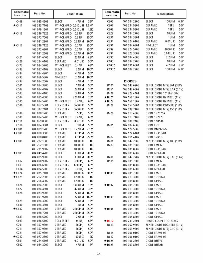
C408 404 085 4609 ELECT 47U M 35V C411 403 343 7703 MT-POLYPRO 0.012U H 1.5KV
404 079 1607 MT-POLYPRO 0.012U H 1.5K C416 403 346 7225 MT-POLYPRO 0.33U J 250V
403 372 7002 MT-POLYPRO 0.33U J 250V404 081 2807 MT-POLYPRO 0.33U M 200V
C417 403 346 7126 MT-POLYPRO 0.27U J 250V403 372 6807 MT-POLYPRO 0.27U J 250V404 081 2609 MT-POLYPRO 0.27U M 200V
C421 404 091 6406 ELECT 220U M 6.3VC426 403 224 6108 CERAMIC 0.01U K 50VC473 404 084 5706 MT-POLYEST 0.47U J 63VC482 404 087 4102 ELECT 22U M 100VC484 404 084 4204 ELECT 4.7U M 50VC493 404 056 5307 NP-ELECT 2.2U M 100VC497 404 084 2507 ELECT 47U M 10VC501 404 084 3900 ELECT 10U M 50VC502 404 084 4402 ELECT 220U M 35VC503 404 084 4105 ELECT 3.3U M 50VC504 404 085 4500 ELECT 2200U M 25VC505 404 084 5706 MT-POLYEST 0.47U J 63VC506 403 062 5301 POLYESTER 5600P K 50V
403 312 2401 POLYESTER 5600P K 50VC508 403 028 1705 CERAMIC 56P J 50VC509 404 084 5706 MT-POLYEST 0.47U J 63V
C511 403 059 8308 POLYESTER 0.22U K 50VC516 404 084 3801 ELECT 1U M 50V
C601 404 089 1703 MT-POLYEST 0.22U M 275V C606 404 088 3500 CERAMIC 470P M 250V
404 088 8406 CERAMIC 470P M 250V C608 403 222 1303 CERAMIC 1000P K 1K
403 262 1806 CERAMIC 1000P K 1K403 271 9602 CERAMIC 1000P K 1K
C609 404 049 4706 ELECT 330U M 200V404 085 9000 ELECT 330U M 200V
C612 404 090 9002 POLYESTER 3300P J 63VC613 404 086 6800 POLYESTER 6800P J 63VC614 404 084 5003 POLYESTER 0.01U J 63V
C624 403 075 7101 CERAMIC 1000P K 500V C625 403 262 2308 CERAMIC 1200P K 1K
403 266 4902 CERAMIC 1200P K 1KC626 404 084 2903 ELECT 1000U M 16VC627 404 084 4501 ELECT 470U M 35VC628 404 073 9005 ELECT 220U M 160V
404 091 9704 ELECT 220U M 160VC629 404 084 3009 ELECT 220U M 16VC630 404 084 3801 ELECT 1U M 50V
C632 404 088 3005 CERAMIC 2200P M 250V404 088 7201 CERAMIC 2200P M 250V
C683 404 088 5702 ELECT 22U M 16VC693 404 086 5100 POLYESTER 0.1U J 63VC701 403 357 9304 CERAMIC 560P J 50VC711 403 357 9304 CERAMIC 560P J 50VC721 403 357 9304 CERAMIC 560P J 50V
C742 403 077 2807 CERAMIC 1000P Z 2KC801 403 224 6108 CERAMIC 0.01U K 50VC802 404 084 3207 ELECT 47U M 16V
C805 404 084 2200 ELECT 100U M 6.3VC807 403 234 9809 CERAMIC 18P J 50VC808 403 234 9809 CERAMIC 18P J 50VC822 404 084 2705 ELECT 10U M 16VC831 404 084 3801 ELECT 1U M 50VC834 403 224 6108 CERAMIC 0.01U K 50VC891 404 084 6901 NP-ELECT 1U M 50VC892 403 224 5705 CERAMIC 1000P K 50VC894 403 323 3602 CERAMIC 0.047U K 50VC896 404 084 4006 ELECT 2.2U M 50VC1001 404 084 2705 ELECT 10U M 16VC1002 404 091 6604 ELECT 4.7U M 25VC1902 404 084 2200 ELECT 100U M 6.3V
DIODES
D101 408 047 6205 ZENER DIODE MTZJ36A (36V)D351 408 047 6502 ZENER DIODE MTZJ5.1A (5.1V)D408 407 222 4401 ZENER DIODE 1Z150 (150V)
D421 407 158 1307 ZENER DIODE HZ11B2L (11V) D422 407 158 1307 ZENER DIODE HZ11B2L (11V)
D428 407 054 5904 ZENER DIODE RD15EB3 (15V)407 099 7109 ZENER DIODE MTZJ15C (15V)
D429 407 013 4306 DIODE 1S2076A407 013 7109 DIODE 1S2473408 008 2406 DIODE 1N4148
D481 407 007 6606 DIODE ES1407 124 5506 DIODE RMPG06G407 124 6404 DIODE ERA18-04
D482 407 011 4407 DIODE TVR1GD486 408 047 2306 ZENER DIODE MTZJ10B (10V)D487 407 005 7308 DIODE EM01Z
407 005 8602 DIODE ERA15-02407 088 6502 DIODE MPG06D
D490 408 047 7707 ZENER DIODE MTZJ5.6C (5.6V)D501 407 005 7308 DIODE EM01Z
407 005 8602 DIODE ERA15-02407 088 6502 DIODE MPG06D
D601 407 005 7605 DIODE EM2B407 013 3200 DIODE 1S1887A408 008 8606 DIODE GP15G
D602 407 005 7605 DIODE EM2B407 013 3200 DIODE 1S1887A408 008 8606 DIODE GP15G
D603 407 005 7605 DIODE EM2B407 013 3200 DIODE 1S1887A408 008 8606 DIODE GP15G
D604 407 005 7605 DIODE EM2B407 013 3200 DIODE 1S1887A408 008 8606 DIODE GP15G
D612 407 231 2801 PHOTO COUPLE PC123YC2D613 407 057 9800 ZENER DIODE RD9.1EB3 (9.1V)
407 063 9702 ZENER DIODE MTZJ9.1C (9.1V)D614 407 006 0100 DIODE ERA91-02D617 407 006 0100 DIODE ERA91-02
D624 407 106 2806 DIODE RU3YX D625 407 009 8806 DIODE RU3AM
— 15 —
Schematic
LocationPart No. Description
Schematic
LocationPart No. Description
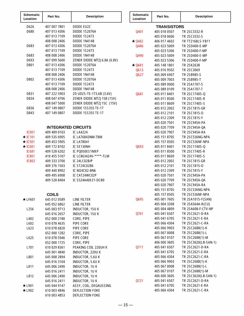
D626 407 007 7801 DIODE EU2ZD680 407 013 4306 DIODE 1S2076A
407 013 7109 DIODE 1S2473408 008 2406 DIODE 1N4148
D683 407 013 4306 DIODE 1S2076A407 013 7109 DIODE 1S2473
D683 408 008 2406 DIODE 1N4148D693 407 099 5600 ZENER DIODE MTZJ6.8A (6.8V)D801 407 013 4306 DIODE 1S2076A
407 013 7109 DIODE 1S2473408 008 2406 DIODE 1N4148
D802 407 013 4306 DIODE 1S2076A407 013 7109 DIODE 1S2473408 008 2406 DIODE 1N4148
D831 407 222 5903 ZD UDZS-TE-173.6B (3.6V)D834 408 047 4706 ZENER DIODE MTZJ15B (15V)
408 047 5000 ZENER DIODE MTZJ15C (15V)D836 407 149 0807 DIODE 1SS355 TE-17D843 407 149 0807 DIODE 1SS355 TE-17
INTEGRATED CIRCUITS
IC001 409 489 0103 IC LA4224 IC101 409 535 6905 IC LA76843NM-TBM IC501 409 453 5905 IC LA78041 IC601 409 172 8102 IC SE130NH
IC681 409 528 6202 IC PQ050ES1MXPIC801 410 455 5107 IC LC863424V-****-TLMIC802 409 333 3700 IC 24LC02B/P
409 376 1503 IC ST24C02B6409 440 8902 IC M24C02-BN6409 495 6908 IC CAT24WC02P409 528 8404 IC S524A40X21-DCB0
COILS
LF601 645 012 0589 LINE FILTER645 052 6862 LINE FILTER
L256 645 003 9713 INDUCTOR, 15U K645 016 2657 INDUCTOR, 15U K
L402 652 000 2180 CORE, PIPEL602 610 078 4635 PIPE COREL623 610 078 6820 PIPE CORE
652 000 1282 CORE, PIPEL625 610 078 5946 PIPE CORE
652 000 1725 CORE, PIPEL701 610 029 8361 PEAKING COIL 220UH K
645 001 4840 INDUCTOR, 220U KL801 645 008 2894 INDUCTOR, 5.6U K
645 016 3104 INDUCTOR, 5.6U KL811 645 006 2490 INDUCTOR, 1U K
645 016 2411 INDUCTOR, 1U KL812 645 006 2490 INDUCTOR, 1U K
645 016 2411 INDUCTOR, 1U K L901 645 044 9147 ASSY, COIL, DEGAUSSING L902 610 003 4846 DEFLECTION YOKE
610 003 4853 DEFLECTION YOKE
TRANSISTORS
Q401 405 018 0507 TR 2SC3332-R405 018 0606 TR 2SC3332-S
Q402 406 017 4602 TR TT2168LS-YB11Q486 405 023 5009 TR 2SD400-E-MP
405 023 5306 TR 2SD400-F-MPQ490 405 023 5009 TR 2SD400-E-MP
405 023 5306 TR 2SD400-F-MP Q601 405 148 1801 TR 2SK2638
Q613 405 016 9502 TR 2SC3069Q627 405 009 6907 TR 2SB985-S
405 009 7003 TR 2SB985-T405 089 0000 TR 2SA1707-S405 089 0109 TR 2SA1707-T
Q681 405 011 8401 TR 2SC1740S-Q405 011 8500 TR 2SC1740S-R405 011 8609 TR 2SC1740S-S405 012 2002 TR 2SC1815-GR405 012 2101 TR 2SC1815-O405 012 2309 TR 2SC1815-Y405 020 7501 TR 2SC945A-PA405 020 7709 TR 2SC945A-QA405 020 7907 TR 2SC945A-RA405 151 8705 TR 2SC536NG-NPA405 157 0505 TR 2SC536NF-NPA
Q693 405 011 8401 TR 2SC1740S-Q405 011 8500 TR 2SC1740S-R405 011 8609 TR 2SC1740S-S405 012 2002 TR 2SC1815-GR405 012 2101 TR 2SC1815-O405 012 2309 TR 2SC1815-Y405 020 7501 TR 2SC945A-PA405 020 7709 TR 2SC945A-QA405 020 7907 TR 2SC945A-RA405 151 8705 TR 2SC536NG-NPA405 157 0505 TR 2SC536NF-NPA
Q695 405 001 7605 TR 2SA1015-Y(SAN)405 004 3208 TR 2SA564A-R(CU)405 004 4809 TR 2SA608-F-CTV-NP
Q701 405 041 6507 TR 2SC2621-D-RA405 041 6705 TR 2SC2621-E-RA405 066 4304 TR 2SC2621-C-RA405 066 9903 TR 2SC2688(1)-K405 067 0008 TR 2SC2688(1)-L405 067 0107 TR 2SC2688(1)-M406 000 3605 TR 2SC3620(LB-SAN-1)
Q711 405 041 6507 TR 2SC2621-D-RA405 041 6705 TR 2SC2621-E-RA405 066 4304 TR 2SC2621-C-RA405 066 9903 TR 2SC2688(1)-K405 067 0008 TR 2SC2688(1)-L405 067 0107 TR 2SC2688(1)-M406 000 3605 TR 2SC3620(LB-SAN-1)
Q721 405 041 6507 TR 2SC2621-D-RA405 041 6705 TR 2SC2621-E-RA405 066 4304 TR 2SC2621-C-RA
Schematic
LocationPart No. Description
Schematic
LocationPart No. Description
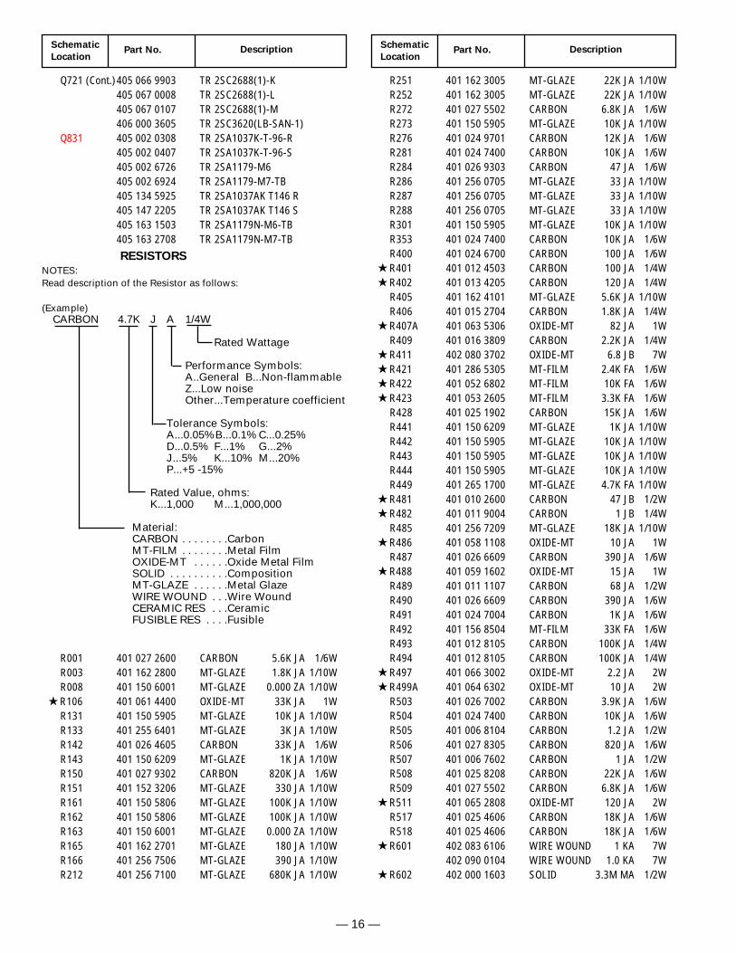
Q721 (Cont.)405 066 9903 TR 2SC2688(1)-K405 067 0008 TR 2SC2688(1)-L405 067 0107 TR 2SC2688(1)-M406 000 3605 TR 2SC3620(LB-SAN-1)
Q831 405 002 0308 TR 2SA1037K-T-96-R405 002 0407 TR 2SA1037K-T-96-S405 002 6726 TR 2SA1179-M6405 002 6924 TR 2SA1179-M7-TB405 134 5925 TR 2SA1037AK T146 R405 147 2205 TR 2SA1037AK T146 S405 163 1503 TR 2SA1179N-M6-TB405 163 2708 TR 2SA1179N-M7-TB
R001 401 027 2600 CARBON 5.6K JA 1/6WR003 401 162 2800 MT-GLAZE 1.8K JA 1/10WR008 401 150 6001 MT-GLAZE 0.000 ZA 1/10W
R106 401 061 4400 OXIDE-MT 33K JA 1WR131 401 150 5905 MT-GLAZE 10K JA 1/10WR133 401 255 6401 MT-GLAZE 3K JA 1/10WR142 401 026 4605 CARBON 33K JA 1/6WR143 401 150 6209 MT-GLAZE 1K JA 1/10WR150 401 027 9302 CARBON 820K JA 1/6WR151 401 152 3206 MT-GLAZE 330 JA 1/10WR161 401 150 5806 MT-GLAZE 100K JA 1/10WR162 401 150 5806 MT-GLAZE 100K JA 1/10WR163 401 150 6001 MT-GLAZE 0.000 ZA 1/10WR165 401 162 2701 MT-GLAZE 180 JA 1/10WR166 401 256 7506 MT-GLAZE 390 JA 1/10WR212 401 256 7100 MT-GLAZE 680K JA 1/10W
R251 401 162 3005 MT-GLAZE 22K JA 1/10WR252 401 162 3005 MT-GLAZE 22K JA 1/10WR272 401 027 5502 CARBON 6.8K JA 1/6WR273 401 150 5905 MT-GLAZE 10K JA 1/10WR276 401 024 9701 CARBON 12K JA 1/6WR281 401 024 7400 CARBON 10K JA 1/6WR284 401 026 9303 CARBON 47 JA 1/6WR286 401 256 0705 MT-GLAZE 33 JA 1/10WR287 401 256 0705 MT-GLAZE 33 JA 1/10WR288 401 256 0705 MT-GLAZE 33 JA 1/10WR301 401 150 5905 MT-GLAZE 10K JA 1/10WR353 401 024 7400 CARBON 10K JA 1/6WR400 401 024 6700 CARBON 100 JA 1/6W
R401 401 012 4503 CARBON 100 JA 1/4W R402 401 013 4205 CARBON 120 JA 1/4W
R405 401 162 4101 MT-GLAZE 5.6K JA 1/10WR406 401 015 2704 CARBON 1.8K JA 1/4W
R407A 401 063 5306 OXIDE-MT 82 JA 1WR409 401 016 3809 CARBON 2.2K JA 1/4W
R411 402 080 3702 OXIDE-MT 6.8 JB 7W R421 401 286 5305 MT-FILM 2.4K FA 1/6W R422 401 052 6802 MT-FILM 10K FA 1/6W R423 401 053 2605 MT-FILM 3.3K FA 1/6W
R428 401 025 1902 CARBON 15K JA 1/6WR441 401 150 6209 MT-GLAZE 1K JA 1/10WR442 401 150 5905 MT-GLAZE 10K JA 1/10WR443 401 150 5905 MT-GLAZE 10K JA 1/10WR444 401 150 5905 MT-GLAZE 10K JA 1/10WR449 401 265 1700 MT-GLAZE 4.7K FA 1/10W
R481 401 010 2600 CARBON 47 JB 1/2W R482 401 011 9004 CARBON 1 JB 1/4W
R485 401 256 7209 MT-GLAZE 18K JA 1/10W R486 401 058 1108 OXIDE-MT 10 JA 1W
R487 401 026 6609 CARBON 390 JA 1/6W R488 401 059 1602 OXIDE-MT 15 JA 1W
R489 401 011 1107 CARBON 68 JA 1/2WR490 401 026 6609 CARBON 390 JA 1/6WR491 401 024 7004 CARBON 1K JA 1/6WR492 401 156 8504 MT-FILM 33K FA 1/6WR493 401 012 8105 CARBON 100K JA 1/4WR494 401 012 8105 CARBON 100K JA 1/4W
R497 401 066 3002 OXIDE-MT 2.2 JA 2W R499A 401 064 6302 OXIDE-MT 10 JA 2W
R503 401 026 7002 CARBON 3.9K JA 1/6WR504 401 024 7400 CARBON 10K JA 1/6WR505 401 006 8104 CARBON 1.2 JA 1/2WR506 401 027 8305 CARBON 820 JA 1/6WR507 401 006 7602 CARBON 1 JA 1/2WR508 401 025 8208 CARBON 22K JA 1/6WR509 401 027 5502 CARBON 6.8K JA 1/6W
R511 401 065 2808 OXIDE-MT 120 JA 2WR517 401 025 4606 CARBON 18K JA 1/6WR518 401 025 4606 CARBON 18K JA 1/6W
R601 402 083 6106 WIRE WOUND 1 KA 7W402 090 0104 WIRE WOUND 1.0 KA 7W
R602 402 000 1603 SOLID 3.3M MA 1/2W
— 16 —
RESISTORS
NOTES:Read description of the Resistor as follows:
(Example)CARBON 4.7K J A 1/4W
Rated Wattage
Performance Symbols:A..General B...Non-flammableZ...Low noiseOther...Temperature coefficient
Tolerance Symbols:A...0.05%B...0.1% C...0.25%D...0.5% F...1% G...2%J...5% K...10% M...20%P...+5 -15%
Rated Value, ohms:K...1,000 M...1,000,000
Material:CARBON . . . . . . . .CarbonMT-FILM . . . . . . . .Metal FilmOXIDE-MT . . . . . .Oxide Metal FilmSOLID . . . . . . . . . .CompositionMT-GLAZE . . . . . .Metal GlazeWIRE WOUND . . .Wire WoundCERAMIC RES . . .CeramicFUSIBLE RES . . . .Fusible
— 17 —
Schematic
LocationPart No. Description
Schematic
LocationPart No. Description
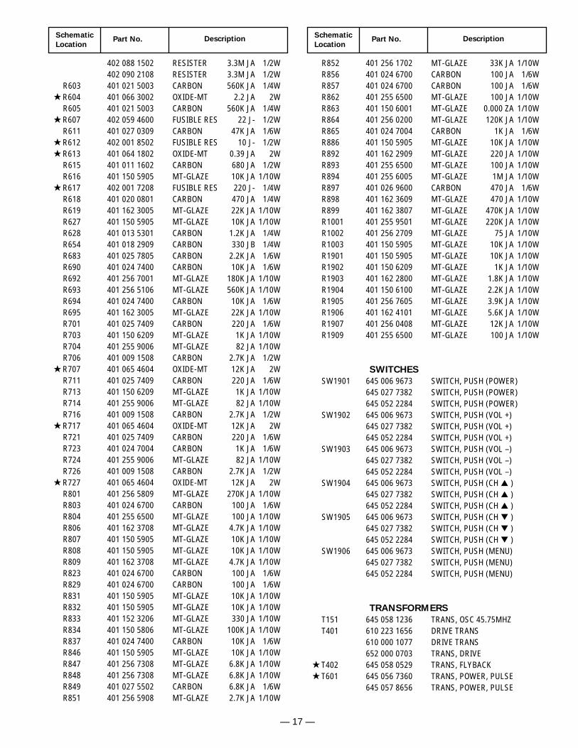
402 088 1502 RESISTER 3.3M JA 1/2W402 090 2108 RESISTER 3.3M JA 1/2W
R603 401 021 5003 CARBON 560K JA 1/4W R604 401 066 3002 OXIDE-MT 2.2 JA 2W
R605 401 021 5003 CARBON 560K JA 1/4W R607 402 059 4600 FUSIBLE RES 22 J- 1/2W
R611 401 027 0309 CARBON 47K JA 1/6W R612 402 001 8502 FUSIBLE RES 10 J- 1/2W R613 401 064 1802 OXIDE-MT 0.39 JA 2W
R615 401 011 1602 CARBON 680 JA 1/2WR616 401 150 5905 MT-GLAZE 10K JA 1/10W
R617 402 001 7208 FUSIBLE RES 220 J- 1/4WR618 401 020 0801 CARBON 470 JA 1/4WR619 401 162 3005 MT-GLAZE 22K JA 1/10WR627 401 150 5905 MT-GLAZE 10K JA 1/10WR628 401 013 5301 CARBON 1.2K JA 1/4WR654 401 018 2909 CARBON 330 JB 1/4WR683 401 025 7805 CARBON 2.2K JA 1/6WR690 401 024 7400 CARBON 10K JA 1/6WR692 401 256 7001 MT-GLAZE 180K JA 1/10WR693 401 256 5106 MT-GLAZE 560K JA 1/10WR694 401 024 7400 CARBON 10K JA 1/6WR695 401 162 3005 MT-GLAZE 22K JA 1/10WR701 401 025 7409 CARBON 220 JA 1/6WR703 401 150 6209 MT-GLAZE 1K JA 1/10WR704 401 255 9006 MT-GLAZE 82 JA 1/10WR706 401 009 1508 CARBON 2.7K JA 1/2W
R707 401 065 4604 OXIDE-MT 12K JA 2WR711 401 025 7409 CARBON 220 JA 1/6WR713 401 150 6209 MT-GLAZE 1K JA 1/10WR714 401 255 9006 MT-GLAZE 82 JA 1/10WR716 401 009 1508 CARBON 2.7K JA 1/2W
R717 401 065 4604 OXIDE-MT 12K JA 2WR721 401 025 7409 CARBON 220 JA 1/6WR723 401 024 7004 CARBON 1K JA 1/6WR724 401 255 9006 MT-GLAZE 82 JA 1/10WR726 401 009 1508 CARBON 2.7K JA 1/2W
R727 401 065 4604 OXIDE-MT 12K JA 2WR801 401 256 5809 MT-GLAZE 270K JA 1/10WR803 401 024 6700 CARBON 100 JA 1/6WR804 401 255 6500 MT-GLAZE 100 JA 1/10WR806 401 162 3708 MT-GLAZE 4.7K JA 1/10WR807 401 150 5905 MT-GLAZE 10K JA 1/10WR808 401 150 5905 MT-GLAZE 10K JA 1/10WR809 401 162 3708 MT-GLAZE 4.7K JA 1/10WR823 401 024 6700 CARBON 100 JA 1/6WR829 401 024 6700 CARBON 100 JA 1/6WR831 401 150 5905 MT-GLAZE 10K JA 1/10WR832 401 150 5905 MT-GLAZE 10K JA 1/10WR833 401 152 3206 MT-GLAZE 330 JA 1/10WR834 401 150 5806 MT-GLAZE 100K JA 1/10WR837 401 024 7400 CARBON 10K JA 1/6WR846 401 150 5905 MT-GLAZE 10K JA 1/10WR847 401 256 7308 MT-GLAZE 6.8K JA 1/10WR848 401 256 7308 MT-GLAZE 6.8K JA 1/10WR849 401 027 5502 CARBON 6.8K JA 1/6WR851 401 256 5908 MT-GLAZE 2.7K JA 1/10W
R852 401 256 1702 MT-GLAZE 33K JA 1/10WR856 401 024 6700 CARBON 100 JA 1/6WR857 401 024 6700 CARBON 100 JA 1/6WR862 401 255 6500 MT-GLAZE 100 JA 1/10WR863 401 150 6001 MT-GLAZE 0.000 ZA 1/10WR864 401 256 0200 MT-GLAZE 120K JA 1/10WR865 401 024 7004 CARBON 1K JA 1/6WR886 401 150 5905 MT-GLAZE 10K JA 1/10WR892 401 162 2909 MT-GLAZE 220 JA 1/10WR893 401 255 6500 MT-GLAZE 100 JA 1/10WR894 401 255 6005 MT-GLAZE 1M JA 1/10WR897 401 026 9600 CARBON 470 JA 1/6WR898 401 162 3609 MT-GLAZE 470 JA 1/10WR899 401 162 3807 MT-GLAZE 470K JA 1/10WR1001 401 255 9501 MT-GLAZE 220K JA 1/10WR1002 401 256 2709 MT-GLAZE 75 JA 1/10WR1003 401 150 5905 MT-GLAZE 10K JA 1/10WR1901 401 150 5905 MT-GLAZE 10K JA 1/10WR1902 401 150 6209 MT-GLAZE 1K JA 1/10WR1903 401 162 2800 MT-GLAZE 1.8K JA 1/10WR1904 401 150 6100 MT-GLAZE 2.2K JA 1/10WR1905 401 256 7605 MT-GLAZE 3.9K JA 1/10WR1906 401 162 4101 MT-GLAZE 5.6K JA 1/10WR1907 401 256 0408 MT-GLAZE 12K JA 1/10WR1909 401 255 6500 MT-GLAZE 100 JA 1/10W
SWITCHES
SW1901 645 006 9673 SWITCH, PUSH (POWER)645 027 7382 SWITCH, PUSH (POWER)645 052 2284 SWITCH, PUSH (POWER)
SW1902 645 006 9673 SWITCH, PUSH (VOL +)645 027 7382 SWITCH, PUSH (VOL +)645 052 2284 SWITCH, PUSH (VOL +)
SW1903 645 006 9673 SWITCH, PUSH (VOL –)645 027 7382 SWITCH, PUSH (VOL –)645 052 2284 SWITCH, PUSH (VOL –)
SW1904 645 006 9673 SWITCH, PUSH (CH )645 027 7382 SWITCH, PUSH (CH )645 052 2284 SWITCH, PUSH (CH )
SW1905 645 006 9673 SWITCH, PUSH (CH )645 027 7382 SWITCH, PUSH (CH )645 052 2284 SWITCH, PUSH (CH )
SW1906 645 006 9673 SWITCH, PUSH (MENU)645 027 7382 SWITCH, PUSH (MENU)645 052 2284 SWITCH, PUSH (MENU)
TRANSFORMERS
T151 645 058 1236 TRANS, OSC 45.75MHZT401 610 223 1656 DRIVE TRANS
610 000 1077 DRIVE TRANS652 000 0703 TRANS, DRIVE
T402 645 058 0529 TRANS, FLYBACK T601 645 056 7360 TRANS, POWER, PULSE
645 057 8656 TRANS, POWER, PULSE
— 18 —
SchematicLocation
Part No. DescriptionSchematicLocation
Part No. Description
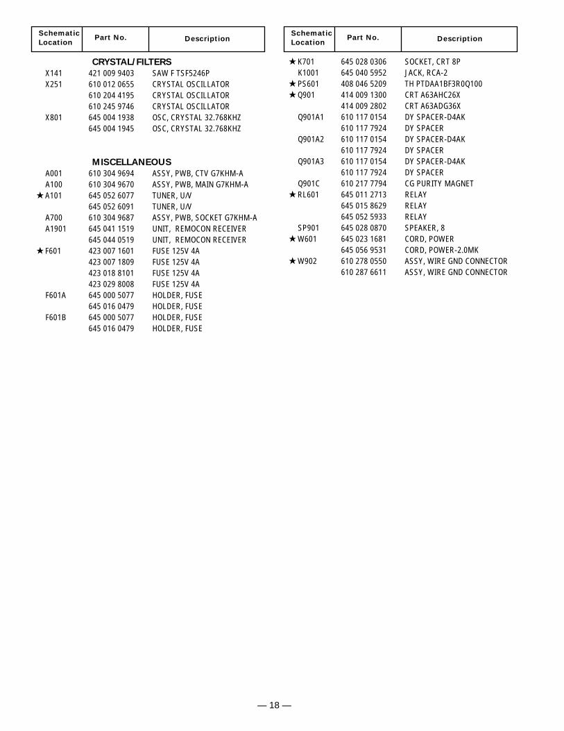
CRYSTAL/FILTERS
X141 421 009 9403 SAW F TSF5246PX251 610 012 0655 CRYSTAL OSCILLATOR
610 204 4195 CRYSTAL OSCILLATOR610 245 9746 CRYSTAL OSCILLATOR
X801 645 004 1938 OSC, CRYSTAL 32.768KHZ645 004 1945 OSC, CRYSTAL 32.768KHZ
MISCELLANEOUS
A001 610 304 9694 ASSY, PWB, CTV G7KHM-AA100 610 304 9670 ASSY, PWB, MAIN G7KHM-A
A101 645 052 6077 TUNER, U/V645 052 6091 TUNER, U/V
A700 610 304 9687 ASSY, PWB, SOCKET G7KHM-AA1901 645 041 1519 UNIT, REMOCON RECEIVER
645 044 0519 UNIT, REMOCON RECEIVER F601 423 007 1601 FUSE 125V 4A
423 007 1809 FUSE 125V 4A423 018 8101 FUSE 125V 4A423 029 8008 FUSE 125V 4A
F601A 645 000 5077 HOLDER, FUSE645 016 0479 HOLDER, FUSE
F601B 645 000 5077 HOLDER, FUSE645 016 0479 HOLDER, FUSE
K701 645 028 0306 SOCKET, CRT 8PK1001 645 040 5952 JACK, RCA-2
PS601 408 046 5209 TH PTDAA1BF3R0Q100 Q901 414 009 1300 CRT A63AHC26X
414 009 2802 CRT A63ADG36XQ901A1 610 117 0154 DY SPACER-D4AK
610 117 7924 DY SPACERQ901A2 610 117 0154 DY SPACER-D4AK
610 117 7924 DY SPACERQ901A3 610 117 0154 DY SPACER-D4AK
610 117 7924 DY SPACERQ901C 610 217 7794 CG PURITY MAGNET
RL601 645 011 2713 RELAY645 015 8629 RELAY645 052 5933 RELAY
SP901 645 028 0870 SPEAKER, 8 W601 645 023 1681 CORD, POWER
645 056 9531 CORD, POWER-2.0MK W902 610 278 0550 ASSY, WIRE GND CONNECTOR
610 287 6611 ASSY, WIRE GND CONNECTOR
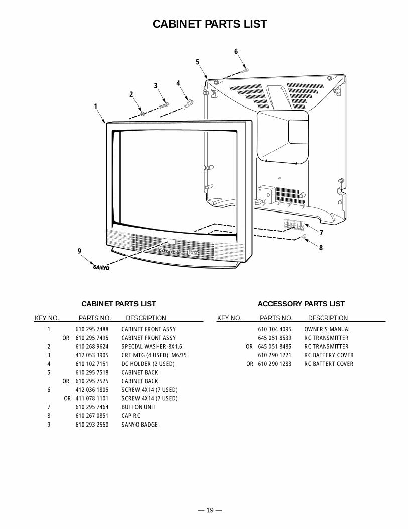
— 19 —
CABINET PARTS LIST
1 610 295 7488 CABINET FRONT ASSYOR 610 295 7495 CABINET FRONT ASSY
2 610 268 9624 SPECIAL WASHER-8X1.63 412 053 3905 CRT MTG (4 USED) M6/354 610 102 7151 DC HOLDER (2 USED)5 610 295 7518 CABINET BACK
OR 610 295 7525 CABINET BACK6 412 036 1805 SCREW 4X14 (7 USED)
OR 411 078 1101 SCREW 4X14 (7 USED)7 610 295 7464 BUTTON UNIT8 610 267 0851 CAP RC9 610 293 2560 SANYO BADGE
610 304 4095 OWNER’S MANUAL645 051 8539 RC TRANSMITTER
OR 645 051 8485 RC TRANSMITTER610 290 1221 RC BATTERY COVER
OR 610 290 1283 RC BATTERT COVER
CABINET PARTS LIST
KEY NO. PARTS NO. DESCRIPTION
ACCESSORY PARTS LIST
KEY NO. PARTS NO. DESCRIPTION
56
7
9 8
1
432
AS
VIDEO IN L-AUDIO-R
— 20 —
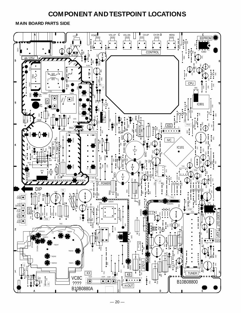
COMPONENT AND TESTPOINT LOCATIONS
B10B08800
85
4 1
VC8C
CONTROL
EEPROMPOWER VOL-UP VOL-DN CH-UP CH-DN MENU
B10B0880A
IC801
E
DIP
26V0.15~0.3A
KTP
GND
DATA
CLK
STATUS
ACK
KX
AUDIO O
UT
????41
13
E
TP7
TE7
1 5
IC101
TJ3
TJ5
TP50
TP51
TP113
TP132
TP11
TP16
14
POWER
TUNER
IVC
CPU
V-OUT
H-OUT
14
5 8
E
E
EE
E
E
3
2
1
4A 125V4A 125V
TJ2
KD
43 2
1
E
17
10
16 16107
1
F601
TJ6
TP814
TJ1
12
TP10
E
C B
17
IC802
D834
L821
X801
C891
C802
C822
C831
L801
C896
SW1903 SW1904SW1902 SW1905SW1901 SW1906
R865
R897
C131C147
C272
C284
C509
C403
C253C258
C211C153C212 X251
T151
C401
C252
C405
C505
KS
L146
X141
C151
R829R823
R849
R272
R513
C1902
R517R518
C421
R503
C106R512
C501
C516
R509
R506
R504R508
C503
C506
KT5P
KT4P
KT3P
KT2P
KT1P
C101
D101
C504
C502
R491
R494
R493
D487
R497
C481
D481
C493
R497A
D483
R481
R492
C487C482
KB
R483 Q401
C511A R511
KX1P KX3P KX4P KX5P
R406
L402
C416C417
T401
C511
R410
L404
C407C406
C408
R106
A101
R411
C473
R353
R507
C411
D409
R408
D351
R857
R856
D801
C416A
C417A
D422
D421
R421
R482 C484
R428
R422
D482 D428
R423
D429
R498
T401A
R411A
R505
R837
Q490
D490
R490
C508
J401
J1901
J147
J504J107
J501
J407
J412
J414J406
J413
J408
J405
J502
J106
J802L812
L811J816J813
J421
J801
J1902
J424
J281 J444
J282
J809
R142
A1901
L401
R408A
R511A
K1001
KSP
R001
C001
C008
IC001
J101
C011
J132
R401
R499
C497
C1001
R487
Q486
R486
C805D680
R628
Q681
Q627
C693Q
693
R694
D693
Q695
R631
D624
C626
L623D625A
L625
Q635
D627
D629
C683
IC681
C629
C631
C631A
C634
C628
R683
D486
IC601
J623
J621
J803
R402
J482
D802
R882
R881
R884R883
T402H11C
C1002
D683
R686
C689
PS601
R601H2
R601A
PS601B
KD1PKD2P
D604
R601H3
R601
R601H1
C606A
D603 D601
D602
C606
R602
A1A2
F601BF601A
LF601LF601A
J608
C632A
C632
T601H14
T601H7
D612
C633
C633A
T601H2
T601H10
H
C609H2
C609H1
L602
R618
J601
R604R612
C608A
R617
R611
Q613
C613
C614
C612
R613
D613
D614
C609
J102
J103
J814
J832
J831
J002
J108
T601A
RL601
T601
J481
J112J111
C602
C604
J1903
J105
J114
J1904
J252
D408
C601
J116
D501
PS601A
C256
J251
J001
J256
R400
J253
L256
C624C625C625A
C608
J804
J109
J110
J104
J506
J503
J418
J411
R004
R407
D653R654
C627
D626L626
C630
C004
R605
R603
R607
R615
J417
R488
R281
J811
J441
R499AR486A
J271R284
J143
R276
J624
R803
J416
J626J486
R489
D502
R403
KSPA
R150
L846
J113
R496
D625
R407A
R409
J690
R690
D001R007
D617
C611
T402H11A
T402
Q402H1
Q402H2
Q402H3
Q402T402H11
T402H7
T402H5 T402H4
T402H2
T402H1
T402A
T402H9
T402H10
T402B
T402H11B
Q601H2
Q601H1
Q601
IC501H1
IC501H2
IC501H3
IC501
MAIN BOARD PARTS SIDE
— 21 —
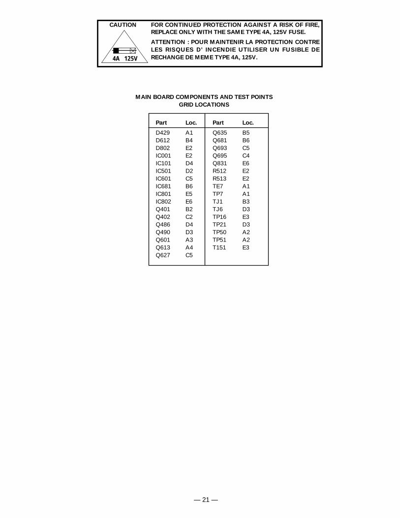
FOR CONTINUED PROTECTION AGAINST A RISK OF FIRE,
REPLACE ONLY WITH THE SAME TYPE 4A, 125V FUSE.
ATTENTION : POUR MAINTENIR LA PROTECTION CONTRE
LES RISQUES D’ INCENDIE UTILISER UN FUSIBLE DE
RECHANGE DE MEME TYPE 4A, 125V.4A 125V
CAUTION
MAIN BOARD COMPONENTS AND TEST POINTS
GRID LOCATIONS
Part Loc.
D429 A1D612 B4D802 E2IC001 E2IC101 D4IC501 D2IC601 C5IC681 B6IC801 E5IC802 E6Q401 B2Q402 C2Q486 D4Q490 D3Q601 A3Q613 A4Q627 C5
Part Loc.
Q635 B5Q681 B6Q693 C5Q695 C4Q831 E6R512 E2R513 E2TE7 A1TP7 A1TJ1 B3TJ6 D3TP16 E3TP21 D3TP50 A2TP51 A2T151 E3
— 22 —
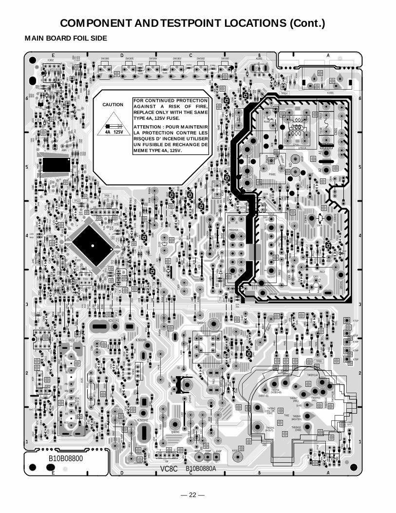
COMPONENT AND TESTPOINT LOCATIONS (Cont.)
MAIN BOARD FOIL SIDE
X
XX
X
X
XXX
X
B10B08800
8 5
41
VC8C B10B0880A
1
10
20
2425
30
40
41
50
60
64 65
70
80
E
1
AGC
AS
SCLSDA
MB
PB
TB
IF
4
1
3
E
5 1
TE7
TP7
TJ3
TJ5
TP36
TP35
TP50
TP51
TP113
TP132
TP11
TP16
TP21
1 4
58
E
E
E E
E
E
12
3
KD
4
32
1
E
17
1016
TJ2
17
10
16
TJ6
TP12
TP814
TJ1
1
TP10
36302019
18 10 1
E
CB
(HEATER)
(AFC)
(ABL)
(GND)
(VERT+B)
(L+B)
(VIDEO+B)
(135V OR 130V)
(H-OUT)
(ABL)
1
2
3
IC802D8
34
L821
X801
C891
C802
C822
C831
L801
C896
SW1903SW1904 SW1902SW1905 SW1901SW1906
R865
R897
C131
C147
C272
C284
C509
C403
C253
C258
C211
C153 C2
12
X251
T151
C401
C252
C405
C505
KS
L146
X141
C151
R829
R823
R849
R272
R513
C190
2
R517
R518
C421
R503
C106
R512
C501
C516
R509
R506
R504
R508
C503
C506
KT5P
KT4P
KT3P
KT2P
KT1P
C101
D101
C504
C502
R491
R494
R493
D487
R497
C481
D481
C493
R497
A
D483
R481
R492C4
87
C482
KB
R483
Q40
1
C511
A
R511
KX1PKX3PKX4PKX5P
R406
L402
C416 C4
17
T401
C511
R410
L404
C407
C406
C408
R106
A101
R411
C473
R353
R507
C411
D409
R408
D351
R857
R856
D801
C416
A
C417
A
D422
D421
R421
R482
C484
R428
R422
D482
D428
R423
D429
R498
T401
A
R411
A
R505
R837
Q49
0
D490
R490
C508
J401
J190
1
J147
J504
J107
J501
J407
J412
J414
J406
J413
J408
J405
J502
J106
J802
L812
L811
J816
J813
J421
J801
J190
2
J424
J281
J444
J282
J809
R142
A1901
L401
R408
A
R511
A
K1001
KSP
R001
C001
C008
IC001
J101
C011
J132
R401
R499
C497
C100
1
R487
Q48
6
R486
C805
D680
R628
Q68
1
Q62
7
C693
Q69
3
R694
D693
Q69
5
R631
D624
C626
L623
D625
A
L625
Q63
5
D627
D629
C683
IC68
1
C629
C631
C631A
C634
C628
R683
D486
IC60
1
J623
J621
J803
R402
J482
D802
R882
R881
R884
R883
T402
H11C
C100
2
D683
R686
C689
PS601
R601
H2
R601
A
PS60
1B
KD1P
KD2P
D604R6
01H3
R601
R601
H1
C606
A
D603D6
01D6
02
C606
R602
A1A2
F601
BF6
01A
LF601LF601A
J608
C632A
C632
T601H14
T601H7
D612
C633C633A
T601
H2
T601
H10
H
C609
H2
C609
H1
L602
R617
R618J6
01
R604
R612
C608
A
Q61
3D6
13
C613
C614
C612
R611
R613
D614
C609
J102
J103
J814
J832
J831
J002
J108
T601A
RL601
T601
J481
J112
J111
C602
C604
J190
3
J105
J114
J190
4
J252
D408
C601
J116
D501
PS60
1A
C256
J251
J001
J256
R400
J253
L256
C624
C625 C6
25A
C608
J804
J109
J110
J104
J506
J503
J418
J411
R004
R407
D653
R654
C627
D626
L626
C630
C004
R605
R603
R607
R615
J417
R488
R281J8
11
J441
R499
A
R486
AJ2
71
R284
J143
R276
J624
R803
J416
J626
J486
R489
D502
R403
KSPA
R150
L846
J113
R496
D625
R407
A
R409
J690
R690
D001
R007
D617
C611
T402H11A
T402
Q402H1
Q40
2H2
Q402H3
Q40
2
T402H11T402H7
T402H5
T402H4
T402H2
T402H1
T402A
T402H9
T402H10
T402B
T402
H11B
Q601H2
Q60
1H1
Q601
IC501H1
IC501H2
IC501H3
IC50
1
R1907
R1906 R1905
R1904 R1903PB
C190
1
R893
C808
C807
C834
R834
C894
R831
R833
C892
R807
C801
R808
R809
R806
C821R894
R898
C811
C812
R801
R832
C862
R862
R863
R864
R892
R847R846
R842
R843
R844
R190
1
D831
Q831
IC80
1
IC101
R165
R163
R301
R212
R252
R251
R442
R441
R443
R444
C257
C221
C282
R405
R287
R286
R288
C285
C803
R161
R162
C146
R131
R143
C143
C426
C141
C142C132
C137
R130
C134
C133
R133
R151
C402
R852
C161
C804
R449
R886
D836
D843
R851
R190
2C8
32
C441
R848
R899
R804
C103
C809
C404
J131
J286
J404
D190
1
R211 R166
R190
9
J257
J508
D190
2
R100
6
R100
1
R003
C003
J806
R629
J631
J632
R632
R634
J634
R695
R627
R691
R693
R692
R485
J891
R100
3
R619
R616
J133
J483
J484
J604J606
J627J628
R100
2
J254
J258
J100
1
J141
J142
J622
C856
C857
R273
C806
C486
C165
C287
C286
C288
R006
R152
R008
FOR CONTINUED PROTECTION
AGAINST A RISK OF FIRE,
REPLACE ONLY WITH THE SAME
TYPE 4A, 125V FUSE.
ATTENTION : POUR MAINTENIR
LA PROTECTION CONTRE LES
RISQUES D’ INCENDIE UTILISER
UN FUSIBLE DE RECHANGE DE
MEME TYPE 4A, 125V.
4A 125V
CAUTION
— 23 —
E
E
E
B10B0880B
15
4 1
???? SCREEN
GND
Q701
Q701A
R706
K7B
R717
R727
R707
R726
R707A
R727A
R717A
K7U
K7U1C742
R716
K7S
K701
R701
C702
Q721A
Q721
Q711Q
711A
R721
R711
R722
R723
K7Y1
K701AL701
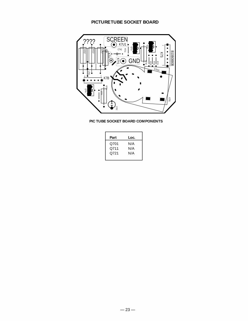
PICTURE TUBE SOCKET BOARD
PIC TUBE SOCKET BOARD COMPONENTS
Part Loc.
Q701 N/AQ711 N/AQ721 N/A

— 24 —
April / 2003 / 2000 SMC Printed in U.S.A.
For parts or service contact
21605 Plummer Street
Chatsworth, CA 91311 (U.S.A.)
300 Applewood Crescent,
Concord, Ontario L4K 5C7 (CANADA)
SANYO Fisher Service Corporation
MODEL DS25320 Chassis No. 25320-06
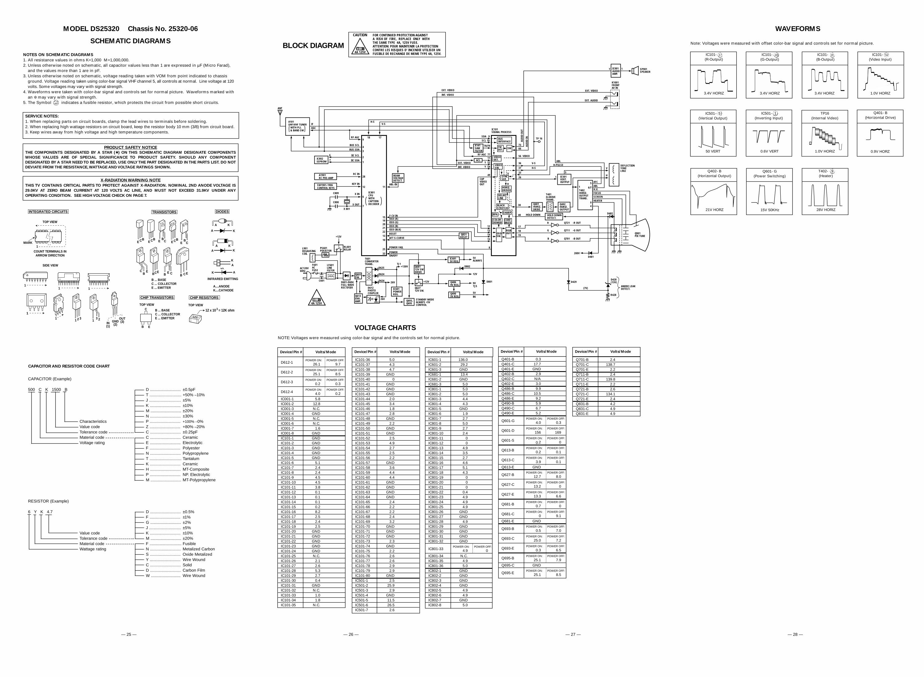
SCHEMATIC DIAGRAMS
CAPACITOR AND RESISTOR CODE CHART
CAPACITOR (Example)
500 C K 1500 B D ........................... ±0.5pFT ............................ +50% –10%J ............................ ±5%K ........................... ±10%M ........................... ±20%N ........................... ±30%
Characteristics P ........................... +100% –0%Value code Z ........................... +80% –20%Tolerance code C ........................... ±0.25pFMaterial code C ........................... CeramicVoltage rating E ........................... Electrolytic
F ........................... PolyesterN ........................... PolypropyleneT ............................ TantalumK ........................... CeramicH ........................... MT-CompositeP ........................... NP. ElectrolyticM ........................... MT-Polypropylene
RESISTOR (Example)
6 Y K 4.7 D ........................... ±0.5%F ........................... ±1%G ........................... ±2%J ............................ ±5%
Value code K ........................... ±10%Tolerance code M ........................... ±20%Material code F ............................ FusibleWattage rating N ........................... Metalized Carbon
S ........................... Oxide MetalizedY ........................... Wire WoundC ........................... SolidD ........................... Carbon FilmW .......................... Wire Wound
— 25 — — 26 — — 28 —— 27 —
FOR CONTINUED PROTECTION AGAINSTA RISK OF FIRE, REPLACE ONLY WITHTHE SAME TYPE 4A, 125V FUSE.ATTENTION: POUR MAINTENIR LA PROTECTIONCONTRE LES RISQUES D' INCENDIE UTILISER UNFUSIBLE DE RECHANGE DE MEME TYPE 4A, 125V.
CAUTION
4A 125V
BLOCK DIAGRAM
1519202122
1310
25
33
OSD (R)OSD (G)OSD (B)OSD (BLK)
RESET
AFT S-CURVE
POWER FAIL
POWERON/OFF
STANDBY MODEALWAYS +5VCONTROL
Q693,Q695
D612PHOTOCOUPLER
IC601POWERREG.
Q68112V SWDRIVE
IC6815V REG.
D601-D604FULL WAVERECTIFIER
Q613ERR.AMP.
Q601SW.
T601CONVERTERTRANS.LF601
LINEFILTER
PS601POSISTOR
L901DEGAUSINGCOIL
AC120V60Hz
F601ACFUSE
C601
+130VD625TJ1
TJ5
D624
4A 125V
+12V
Q62712V SW.
Y CV IN
12
1314
15
8
OSDSW.
RGBOUT
CONTBRITE
COLORDEMOD
SHARPBPA
BLACKSTRETCH
DELAYLINE
SYNCSEP.
HORIZ.DRIVER
VIDEODET.
FMDET. SW
BUSINTERFACE
IC101SIGNAL PROCESS
SDA 9SCL 10
78/79
11
Y 52
Y 54
49
H
VBEAMVOLTAGEDETECT.
ABL-IN
RF AGC 77
ACL
X141SAWFILTER
A101UHF/VHF TUNER WITH PLL & BAND SW
IFAGC
IC802EEPROM
6
7
A1901RC PRE-AMP
SW1901-1906CONTROL KEYS
RF AGC
BUS SCL
BUS SDA
IIC SCL
IIC SDA
RC IN
KEY IN
X IN
X OUT
9
43
2
1
28
12
6
7
11
1718
IC801CPUWITHCAPTIONDECODER
X 801
ANT
C809
C808
IC501VERT.OUTPUT
Q401HORIZ.DRIVE
T401H-DRIVETRANS.
Q402HORIZ.OUTPUT
HOLD DOWNDETECT.
30
40
17
18
19
HOLD DOWN
T402HORIZ.OUTPUTTRANS.
H.V.
DEFLECTIONYOKEL902
ABLAFC
FOCUSSCREENHEATER
6/7
94
51
V
H5
H-PULSEABL
Q721
Q711
Q701
-R OUT
-G OUT
-B OUT
G
R
B
Q901PIX TUBE
(7V)
D429D428(13V)
R428
g7kgm
ANODE LEAKDETECT.
6673
56
36 V-S
TP 16
AUD
IO O
UT
AUD
IO IN
37 H-S
33
26
IC001AUDIOAMP.
7 1 SP901SPEAKER
D482
VIDEO
EXT. VIDEO
INT. VIDEO
1
K1001FRONTAV IN
Q4869V REG.
Q4905V REG.
5VALWAYS
12V
9V
H-SV-S
5VB6
D801
D802
CAPVIDEOOUT
VIDEOSW.
Q831RESET
EXT. VIDEO
INT. VIDEO
EXT. VIDEO
EXT. AUDIO
D626 26V
26V
D481200V
RL601RELAY
+12V
WAVEFORMS
Note: Voltages were measured with offset color-bar signal and controls set for normal picture.
IC101- 17
(R-Output)
3.4V HORIZ
IC101- 18
(G-Output)
3.4V HORIZ
IC101- 19
(B-Output)
3.4V HORIZ
IC101- 52
(Video Input)
1.0V HORIZ
IC501- 5(Vertical Output)
50 VERT
IC501- 1(Inverting Input)
0.6V VERT
TP16 (Internal Video)
1.0V HORIZ
Q401- B(Horizontal Drive)
0.9V HORZ
Q402- B(Horizontal Output)
21V HORZ
T402- 9(Heater)
28V HORIZ
Q601- G(Power Switching)
15V 50KHz
Device/Pin # Volts/Mode
IC101-36 5.0IC101-37 4.3IC101-38 4.7IC101-39 GNDIC101-40 0IC101-41 GNDIC101-42 GNDIC101-43 GNDIC101-44 2.0IC101-45 3.4IC101-46 1.8IC101-47 2.8IC101-48 GNDIC101-49 2.2IC101-50 GNDIC101-51 GNDIC101-52 2.5IC101-53 4.9IC101-54 2.7IC101-55 2.5IC101-56 2.2IC101-57 GNDIC101-58 3.6IC101-59 4.4IC101-60 4.4IC101-61 GNDIC101-62 GNDIC101-63 GNDIC101-64 GNDIC101-65 2.4IC101-66 2.2IC101-67 2.2IC101-68 2.4IC101-69 3.2IC101-70 GNDIC101-71 GNDIC101-72 GNDIC101-73 2.3IC101-74 GNDIC101-75 2.2IC101-76 2.6IC101-77 2.6IC101-78 2.9IC101-79 2.9IC101-80 GNDIC501-1 2.5IC501-2 25.9IC501-3 2.9IC501-4 GNDIC501-5 11.5IC501-6 26.5IC501-7 2.6
IC601-1 136.0IC601-2 29.2IC601-3 GNDIC681-1 13.4IC681-2 GNDIC681-3 5.0IC801-1 5.0IC801-2 5.0IC801-3 4.4IC801-4 4.3IC801-5 GNDIC801-6 1.9IC801-7 2.7IC801-8 5.0IC801-9 2.7IC801-10 2.4IC801-11 0IC801-12 0IC801-13 4.9IC801-14 3.5IC801-15 2.7IC801-16 4.6IC801-17 5.1IC801-18 4.3IC801-19 0IC801-20 0IC801-21 0IC801-22 0.4IC801-23 4.9IC801-24 4.9IC801-25 4.9IC801-26 GNDIC801-27 GNDIC801-28 4.9IC801-29 GNDIC801-30 GNDIC801-31 GNDIC801-32 GND
POWER ON: POWER OFF:IC801-33 4.9 0IC801-34 N.C.IC801-35 4.9IC801-36 5.0IC802-1 GNDIC802-2 GNDIC802-3 GNDIC802-4 GNDIC802-5 4.9IC802-6 4.9IC802-7 GNDIC802-8 5.0
Device/Pin # Volts/Mode
POWER ON: POWER OFF:D612-1 26.1 9.7
POWER ON: POWER OFF:D612-2 25.1 8.5
POWER ON: POWER OFF:D612-3 0.2 0.3
POWER ON: POWER OFF:D612-4 4.0 0.2IC001-1 5.8IC001-2 12.8IC001-3 N.C.IC001-4 GNDIC001-5 N.C.IC001-6 N.C.IC001-7 1.6IC001-8 GNDIC101-1 GNDIC101-2 GNDIC101-3 GNDIC101-4 GNDIC101-5 GNDIC101-6 5.1IC101-7 2.4IC101-8 2.4IC101-9 4.5IC101-10 4.5IC101-11 3.8IC101-12 0.1IC101-13 0.1IC101-14 0.1IC101-15 0.2IC101-16 8.2IC101-17 2.5IC101-18 2.4IC101-19 2.5IC101-20 GNDIC101-21 GNDIC101-22 GNDIC101-23 GNDIC101-24 GNDIC101-25 N.C.IC101-26 2.1IC101-27 2.6IC101-28 5.3IC101-29 2.7IC101-30 0.4IC101-31 GNDIC101-32 N.C.IC101-33 1.0IC101-34 1.8IC101-35 N.C.
VOLTAGE CHARTS
NOTE: Voltages were measured using color-bar signal and the controls set for normal picture.
Device/Pin # Volts/Mode
Q401-B 0.3Q401-C 17.7Q401-E GNDQ402-B 2.9Q402-C N/AQ402-E 3.0Q486-B 9.9Q486-C 10.5Q486-E 9.2Q490-B 5.9Q490-C 6.7Q490-E 5.2
POWER ON: POWER OFF:Q601-G 4.0 0.3
POWER ON: POWER OFF:Q601-D 156 169
POWER ON: POWER OFF:Q601-S
0.2 0
POWER ON: POWER OFF:Q613-B 0.2 0.1
POWER ON: POWER OFF:Q613-C 3.9 0.1Q613-E GND
POWER ON: POWER OFF:Q627-B 12.7 8.0
POWER ON: POWER OFF:Q627-C 13.2 0
POWER ON: POWER OFF:Q627-E 13.3 6.6
POWER ON: POWER OFF:Q681-B 0.7 0
POWER ON: POWER OFF:Q681-C 0 9.1Q681-E GND
POWER ON: POWER OFF:Q693-B 0.5 7.0
POWER ON: POWER OFF:Q693-C 25.0 7.2
POWER ON: POWER OFF:Q693-E 0.3 6.5
POWER ON: POWER OFF:Q695-B 25.1 7.9Q695-C GND
POWER ON: POWER OFF:Q695-E 25.1 8.5
Device/Pin # Volts/Mode Device/Pin # Volts/Mode
Q701-B 2.4Q701-C 138.7Q701-E 2.2Q711-B 2.4Q711-C 139.8Q711-E 2.2Q721-B 2.6Q721-C 134.1Q721-E 2.4Q831-B 4.2Q831-C 4.9Q831-E 4.9
SERVICE NOTES:
1. When replacing parts on circuit boards, clamp the lead wires to terminals before soldering.2. When replacing high wattage resistors on circuit board, keep the resistor body 10 mm (3/8) from circuit board.3. Keep wires away from high voltage and high temperature components.
PRODUCT SAFETY NOTICE
THE COMPONENTS DESIGNATED BY A STAR ( ) ON THIS SCHEMATIC DIAGRAM DESIGNATE COMPONENTS
WHOSE VALUES ARE OF SPECIAL SIGNIFICANCE TO PRODUCT SAFETY. SHOULD ANY COMPONENT
DESIGNATED BY A STAR NEED TO BE REPLACED, USE ONLY THE PART DESIGNATED IN THE PARTS LIST. DO NOT
DEVIATE FROM THE RESISTANCE, WATTAGE AND VOLTAGE RATINGS SHOWN.
X-RADIATION WARNING NOTE
THIS TV CONTAINS CRITICAL PARTS TO PROTECT AGAINST X-RADIATION. NOMINAL 2ND ANODE VOLTAGE IS
29.0KV AT ZERO BEAM CURRENT AT 120 VOLTS AC LINE, AND MUST NOT EXCEED 31.9KV UNDER ANY
OPERATING CONDITION. SEE HIGH VOLTAGE CHECK ON PAGE 7.
11 1
1
TOP VIEW
SIDE VIEW
COUNT TERMINALS INARROW DIRECTION
MARK
ECB
A K
A K
A KA K
AK
AK
INFRARED EMITTING
A....ANODEK....CATHODE
INTEGRATED CIRCUITS TRANSISTORS
1
DIODESPHOTO COUPLERS
B ... BASEC ... COLLECTORE ... EMITTER
E CBE CB E C
BE C
BE CB
ECB E CB
ECB
321 3 21 GND(2)IN
(1)
OUT(3)
1 1
TOP VIEW
1
CHIP TRANSISTORS
B
C
E
TOP VIEW
B ... BASEC ... COLLECTORE ... EMITTER
CHIP RESISTORS
TOP VIEW
123
12 x 10 = 12K ohm3
NOTES ON SCHEMATIC DIAGRAMS
1. All resistance values in ohms K=1,000 M=1,000,000.2. Unless otherwise noted on schematic, all capacitor values less than 1 are expressed in µF (Micro Farad),
and the values more than 1 are in pF.3. Unless otherwise noted on schematic, voltage reading taken with VOM from point indicated to chassis
ground. Voltage reading taken using color-bar signal VHF channel 5, all controls at normal. Line voltage at 120volts. Some voltages may vary with signal strength.
4. Waveforms were taken with color-bar signal and controls set for normal picture. Waveforms marked withan may vary with signal strength.
5. The Symbol indicates a fusible resistor, which protects the circuit from possible short circuits.
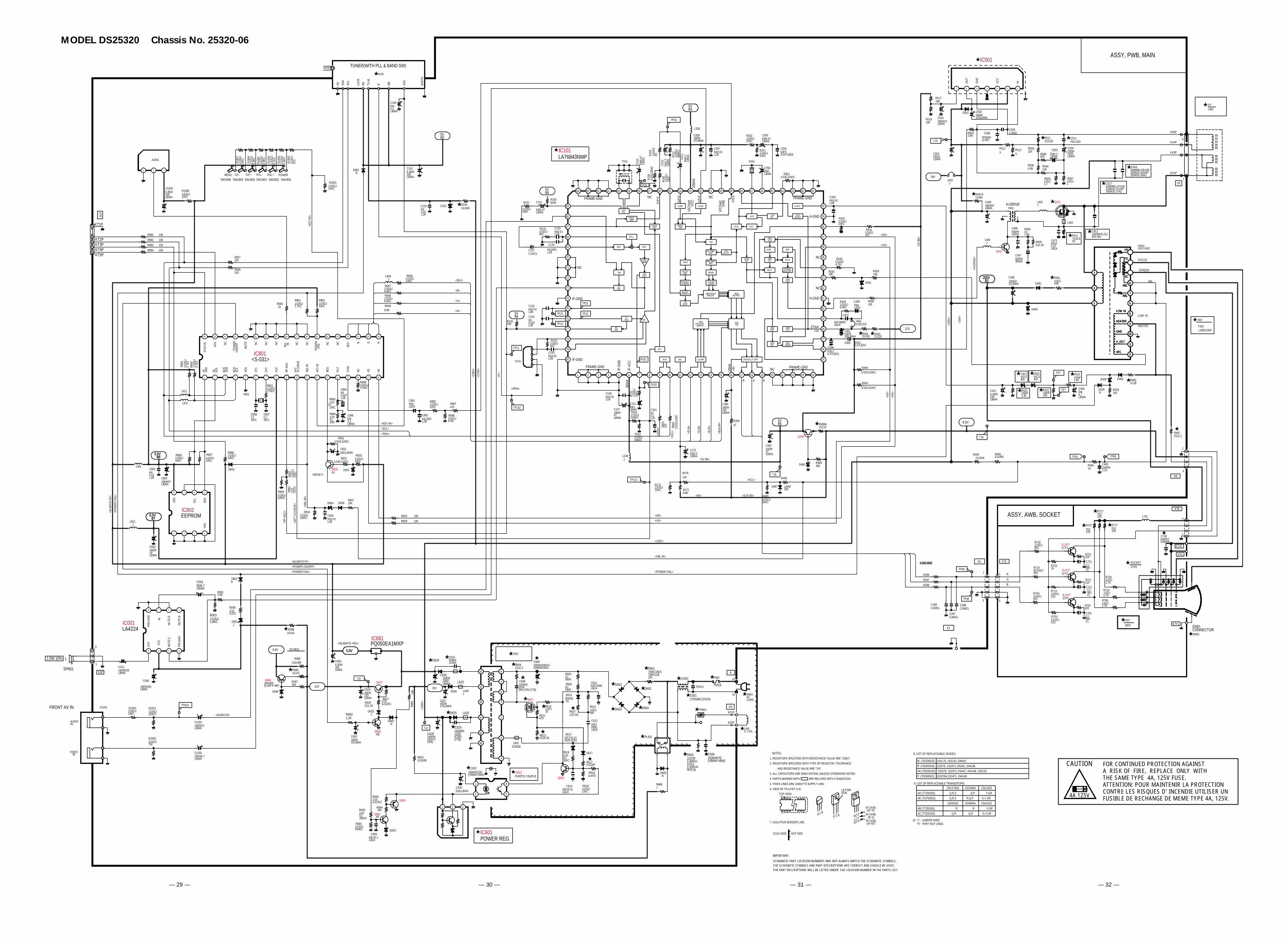
— 29 — — 30 — — 31 — — 32 —
GND-CONNECTOR
DY
CRT
Q901
L1.0W 10%
NOTES;
1. RESISTORS SPECIFIED WITH RESISTANCE VALUE ARE "1/6DJ".
2. RESISTORS SPECIFIED WITH TYPE OF RESISTOR, TOLERANCE
AND RESISTANCE VALUE ARE "1/4".
3. ALL CAPACITORS ARE 50WV RATING UNLESS OTHERWISE NOTED.
4. PARTS MARKED WITH ARE RELATED WITH X-RADIATION.
5. THICK LINES ARE 15WATTS SUPPLY LINE.
6. VIEW OF TR & FET & IC.
7. ISOLATION BORDER LINE.
COLD SIDE HOT SIDE
N
1
TOP VIEWLETTERSIDE
E C BE BCC EB
1 2 3
IN CASE OF TRIN CASE OF IC
IN CASE OF FET
SDG
8. LIST OF REPLACEABLE DIODES.
R (7DD00019) 1S2076, 1S2473, DS442, 1N4148
P (7DD00021) 1S2076A,1S2471, 1N4148
9. LIST OF REPLACEABLE TRANSISTORS.
AE (7QT00202)
AD (7T200183)
AB (7T200181)
2SC945A 2SC1815
2SA564A 2SA1015
R,Q,P
Q,P
Q,R
O,Y,GR
O,Y,GR
Y,GR
10. "J" : JUMPER WIRE."X" : PART NOT USED.
AC (7T200182)
R Y,GR
2SC1740S
Q,R,S
Q,R,S
2SA933S
R
Q,R
AA (7DD00192) 1S2076, 1S2473, DS442, 1N4148, 1SS133
M (7ED00025) 1SS176, 1SS133, GMA01
G-OUT
R-OUT
B-OUT
1
1
4
5
R
G
B
SOCKET
ASSY, AWB, SOCKET
TUNER(WITH PLL & BAND SW)
IF MB
AGC
EART
H
TU+B
PBSCL
SDA
AS LOCK
HEATER
LOW +B
FOCUS
HIGHVOLTAGE
MENU CH - CH + VOL.- VOL.+ POWER
<130
V>
<IF>
<ALW
AYS
5V>
<PO
WER
FAI
L>
EEPROM
VDD
SCL
SDA
VSS <A
FT S
-CUR
VE>
<POWER ON/OFF>
<ALWAYS 5V>
<9V>
<130V>
H-DRIVE
1
4
1
5
<ACL>
<130
V>
<26V
>
<H-D
RIVE
>
1
6
<ABL IN>
<POWER FAIL>
<KEY
-IN>
<POWER FAIL>
<RF
AGC>
VCC
INOUT
GND
<BLK>
<B>
<G>
<R>
KTP
FBT
<SDA>
<SCL>
<ABL
-IN>
<KEY-IN>
<CVI
N>
<R-IN
>
<G-IN
>
<B-IN
>
<BLK
-IN>
<4PIN>
BGR
<SCL
>
<SDA
>
<HS>
<HS>
<VS>
<VS>
<VS>
<HS>
<9.0V B5>
<5V B6>
<5V
B6>
27mA
19m
A
60m
A
100m
A
TP21
TP12
TP20
3
1
MUT
E-C
PW-G
ND
PRE-
GND
OUT VC
CIN
MUT
E-E
AUDIOIN
VIDEOIN
<AUDIO IN>
A
KD
<130
V>
POWER REG.
<ALWAYS +5V>
9V-REG.
FRONT AV IN
MUT
E-B
<RESET>
KX
KY
ASSY, PWB, MAIN
HV
FO
SC
AFC
V_OUT
GND
HEATER
LOW +B
ABL
ABL
HV
FO
SC
AFC
V_OUT
GND
HEATER
LOW +B
ABL
ABL
LIMAMP
FMDET
A2CPLL
VIDEOAMP
VIDEODET
SPLL
BPF BPF
DCVOL
SW
RFAGC
IFAGC VIF
AFT
BUS ABL CLAMP
CLMP CLMP
VIDEOSW
SW
1ST AMPBPF
2ND AMPBPF
DEMO
COLORCLAMP
CONTRASTBRIGHT
TRAP
DELAYLINE
PEAKINGCORING
BLACKSTRETCH
DCREST
RGBMATRIX
OSDSW
OSDFIX GAIN
BRIGHT
DRIVE/CUT-OFF
VERC/D
VERRAMP
HDRVCC
VERSEP
ACCKILLER
SYNCSEP
APC1
VCO
TINT
CWKIL
X-RAY
HDRC/D AFC2
FBP1/256
HDRVCO
PHASESHIFTERAFC1
HDROUT
2VP-
P
1VP-
P
1VP-
P
FRAME-GND
FRAME-GND
FRAME-GND
FRAME-GND
IF-G
ND
IF-V
CC
NC
H-GND
H-GND
V/C/
Vert
GND
NC
V/C/
Vert
VCC
NC
NC
IF-GND
IF-GND
+8V
+5V
2Vp-
p
CPURESET
NC
NC
B G R
BLK
POW
ERFA
ILNCNCR/C INNC
POW
ERO
N/O
FFACK
STAT
US
HSVSCVIN
FILT
RES
KEY-
IN
ABL-
IN
AFT
S-CU
RVE
RF A
GC
VCC
CF2
CF1
VSS
BUS
SCL
BUS
SDA
IIC SDA
IIC SCL
NCNCNCNC
MUT
E
NC
NC
<S-031>
HV
FO
SC
AFC
V_OUT
GND
HEATER
LOW +B
ABL
ABL
SP901
L902
ARW
Q701
R703C701
R713C711
Q711
R723C721
Q721
R707
R717
R727
R716
R726
R706
C742
K7U
K7Y1
R714
R704
R721
R711
R701
K701
K7U1
L701
K7B
K7S
R494
R497
R421
C482
D481
R513
R511
C503R506
R507
C408 Q402
R411
R481
Q401C407
D834
R406
R504R509
R508
R493
R847
R848
R849
R512
ABL
SCREEN
R503
A101
A1901
SW1906 SW1905 SW1904 SW1903 SW1902 SW1901
R190
7
R190
6
R190
5
R190
4
R190
3
R190
2
C103
C101
C822
R807
C421 R423
D421 D422
R422 C484
D482 R482
D487
R892
D101
R834
R837
R492
D836
R491 C493
R106
D843
D428
R428D429
R846
C106
C892
R862
C801
C802
R864 R863
IC501
C511
C504
C502
C508C506
R808
C501
C497
D801
KT2PKT3PKT4PKT5P
KT1P
C516R518
R517
R886
R852
R485
X801
C808 C807 R894
C894
C896
C834
R851
D501
R865
R897
R898
R286
R287
R288
R856
R857
C891
R801
R806
C131
R162
R161C161
R803
R804
C272
C284
R284
C509
C403
R405 C405 R400
R281 R353
R449
R444
R443
R442
R441
R251
X251
C256
R212
C212
C211
C258
C257
R165
C153
R151
C137
R133 C133
C134
C132
C142R142
R143
C143
T151
X141
L402
C416
R272
R276
L146
R163
L256
C252
J404
C401
C505
R490
Q490
D490
R252
D351
R131
C147
C146
C151
C253
C426
R301
R823
R829
C473
R505
C1902
R899
R166
L401
R893
R1909
KSP
C011
C008
D802
R003
C001
IC001
R001
R1002
R1001
C1001
D601D602
D604D603 PS601
R602 C606
C601
R601
LF601 A1
A2
KD1P
KD2P
F601BF601A
F601C626
D624
C628
D625
C625
L625
L623
C624
C632D612
IC601
Q693
Q695
C630
R695
R693
R694R692
C629
R683
Q681
Q627
R627R628
D680
IC681
C683
R401 R402
R487
R486
Q486
D486
R489
R604
C608
Q601
R613
R611
L602
R612
Q613
C614 R619
R617
R618
D613
R616
C613
D614
R607
R603
C612
C609
C1002
C805
R1003
T601
TP814
TJ2
TJ1
TP113
TP132
TP11
TP12
TP21
TP20
TP16
TJ5
TP7
TE7
TP51 TP50
TP36
TP35
D408
R809
C693
C417
RL601
AT3AT3
D683
R686
D626 L626
C627
R488
R1901
R831
C831
Q831
R832R833
D831
D653
R654
R605
R615
TJ3
IC101
IC801
J416
L404
C406
R407A
R881
R882
R883
R884
L801
L821
KB
KS
K1001
D693
KX5P
KX4P
KX3P
KX1P
R273
R499A
TJ6
C411
T402
T401
L811
L812
R150
TP10
L846
C286
C287
C288
R690
R409
D617
R008
D0011/10GJ1KC
CJ560CL
1/10GJ1KC
CJ560CL
1KCJ560CL
2SJ12K
2SJ12K
2SJ12K
1/2DJ2.7K
1/2DJ2.7K
1/2DJ2.7K
2000KZ1000HE
X
X
81/10GJ82C
1/10GJ82C
220
220
220
DJ100K
1/6NF2.4K
100EM22LBWA
X
2SJ120
EM3.3LBWA820
1/2DJ1
35EM47LBWA
7SJ6.8VC
1/2DJ47B
500KK3900A
DJ1.8K
10K6.8K
22K
DJ100K
1/10GJ6.8KC
1/10GJ6.8KC
6.8K
X
3.9K
1/10
GJ
12KC
1/10
GJ
5.6K
C
1/10
GJ
3.9K
C
1/10
GJ
2.2K
C
1/10
GJ
1.8K
C
1/10
GJ
1KC
KK0.01LZB
6.3EM220LBWA
16EM10LBWA
1/10GJ10KC
6.3EM220LBWA
1/6NF3.3K
HZ11B2L
HZ11B2L
1/6NF10K
EM4.7LBWA
DJ1B
1/10GJ220C
1/10GJ100KC
10K
1/6NF33K
1K 100PM2.2X
1SJ33K
15KR
1/10GJ10KC
EM3.3LBWA
KK1000LZB
1/10
GJ
100CKK
0.01LZB
16EM47LBWA
1/10GJ120KC
1/10
GZ0
C
FK0.22D
25EM2200LBWA
35EM220LBWA
CJ56GFK5600(D:BF)
1/10GJ10KC
EM10LBWA
10EM47LBWA
R
16EM10LBWA18K
18K
1/10GJ10KC
1/10GJ33KC
1/10GJ18KC
CJ18CL
CJ18CL
1/10GJ1MC
KK0.047LZB
EM2.2LBWA
KK0.01LZB
1/10GJ2.7KC1K
470
1/10GJ470C
1/10GJ33C1/10GJ33C1/10GJ33C
100
100
PM1LBZA
1/10GJ270KC
1/10
GJ
4.7K
C
EM1LBWA
1/10GJ100KC
1/10GJ100KC
KZ0.1LZF
100
1/10
GJ1
00C
EM3.3LBWA
16EM220LBWA
47
63GJ0.47LBZA
63FJ6800LBZA
1/10GJ5.6KC
PM1LBZA
100
10K 10K
1/10GF4.7KC
1/10GJ10KC
1/10GJ10KC
1/10GJ10KC
1/10GJ1KC
1/10GJ22KC
EM1LBWA
1/10
GJ
680K
C
EM2.
2LB
WA EM
4.7
LBW
A
16EM47LBWA
KK0.01LZB
1/10
GJ
180C
EM0.
47LB
WA
1/10GJ330C
CJ10CL
1/10GJ3KC
KK0.01LZB
KK1000LZB
KK0.01LZB
KK0.022LZB33K
1/10GJ1KC
KK0.01LZB
2400010
2SJ2.2
200MM0.33UVB:250MJ0.33UAP:250MJ0.33AU
6.8K
12K
J
1/10
GZ
0C
63FK0.047LBZB
1/10GZ0C
10EM330LBWA
63GJ0.47LBZA
390
1/10GJ22KC
1/10
GJ
10KC
10EM47LBWA
KK0.01LZB
EM0.47LBWA
EM0.47LBWA
KK0.01LZB
1/10GJ10KC
100
100
63GJ0.47LBZA
1/2DJ1.2
6.3EM100LBWA
1/10GJ470KC
1/10
GJ3
90C
J
1/10GJ100C
1/10GJ100C
16EM220LBWA
16EM330LBWA
R
1/10GJ1.8KC
EM4.7LBWA
LA4224
5.6K
1/10GJ75C
1/10GJ220KC
16EM10LBWA
1/2CM3.3MXU:1/2XJ3.3(MVA:MVCA)
250KM470(VBBW:VBW)
275GM0.22VDA
7WK1VEA:7WK1LBZFL
2400010
2400010
16EM1000LBWA
160EM220(XJ:VEA)
1000KK1200(CRD:CTB)
500KK1000A
250KM2200(VBBW:VBW)
AE
EM1LBWA
1/10GJ22KC
1/10GJ560KC
1/10GJ180KC
10K
16EM220LBWA
2.2K
AE
1/10GJ10KCDJ1.2K
R
PQ050EA1MXP
16EM22LBWA
DJ100 DJ120
390
1SJ10
2SD400(E-MP:F-MP)
1/2DJ68
2SJ2.2
1000KK1000(NH:CRD:CTB)
2SJ0.39
47K
ZZ0008
1/2FJ10
63FJ0.01LBZA
1/10GJ22KC
FJ220P
DJ470
MTZJ9.1C:RD9.1EB3
1/10GJ10KC
63FJ6800LBZA
ERA91-02
1/2FJ22
DJ560K
63FJ3300LBZA
200EM330XG:200EM330XL
25EM4.7LBWA
6.3EM100LBWA
1/10GJ10KC X
X
X
X
X
X
X
X
X
X
X
X
X
X X
X
X
1/10
GJ
4.7K
C
63FJ0.1LBZA
200MM0.27UVB:250MJ0.27UAP:250MJ0.27AU
R
J
J
35EM470LBWA
1SJ15
1/10GJ10KC
1/10GJ10KC
EM1LBWA
AJ
1/10GJ10KC1/10GJ330C
J
DJ330B
DJ560K
1/2DJ680
X
LA76843NMP
J
J
500KK1000A
1SJ82
100
100
100
100
J
1/10GJ10KC
2SJ10
X
1500MH0.012(XK:AN)
L40B15400
820K
X
J
CJ68CL
CJ68CL
CJ68CL
10K
DJ2.2K
1/10GZ0C
J
1 2 3
1 2 3 4
5678
1234567
1
2
3
4
5
6
7
8
9
10
1111
10
9
8
7
6
5
4
3
2
1
1 2 3 4
5678
4
32
1
321
2
3
1
4
5
6
7
16
14
10
11
12
13
2
3
1
4
5
6
7
16
14
10
11
12
13
1 2 3 4 5 6 7 8 9 10 11 12 13 14 15 16 17 18 19 20 21 22 23 24
25
26
27
28
29
30
31
32
33
34
35
36
37
38
39
40
414243444546474849505152535455565758596061626364
65
66
67
68
69
70
71
72
73
74
75
76
77
78
79
80
1 2 3 4 5 6 7 8 9 10 11 12 13 14 15 16 17 18
192021222324252627282930313233343536
6
7
4
5
1
2
3
4
5
6
7
8
9
10
11
12V
5.0V
12V
9.0V
5.0VB7
5.0VB8
5.0VB8
5.0VB7
5VB6
5VB6
5VB6
5VB6
200VB1
200VB1
9.0V
5.0V
26V
26V
5VB6
IC802
IMPORTANT:
SCHEMATIC PART LOCATION NUMBERS MAY NOT ALWAYS MATCH THE SCHEMATIC SYMBOLS.THE SCHEMATIC SYMBOLS AND PART DESCRIPTIONS ARE CORRECT AND SHOULD BE USED.THE PART DESCRIPTIONS WILL BE LISTED UNDER THE LOCATION NUMBER IN THE PARTS LIST.
FOR CONTINUED PROTECTION AGAINSTA RISK OF FIRE, REPLACE ONLY WITHTHE SAME TYPE 4A, 125V FUSE.ATTENTION: POUR MAINTENIR LA PROTECTIONCONTRE LES RISQUES D' INCENDIE UTILISER UNFUSIBLE DE RECHANGE DE MEME TYPE 4A, 125V.
CAUTION
4A 125V
R7281/10GJ82C
PHOTO COUPLE
W902
L901D. COIL
W601ACCORD
MODEL DS25320 Chassis No. 25320-06