Embed Size (px)
Citation preview

For internal use only PHILIPS
ISSUE PA99.05 (99-12-03)Published by:Service Department Portable Audio
LINE OF BUSINESS PORTABLE AUDIO
05.01 TYPENUMBER(S) : AE6775, AE6780
SYMPTOM :No battery contact for some battery types only.
CURE : The ribs for fixing the battery contact wire are too close together forbatteries with large plus-pole diameter. For such battery types theplus-pole of the upper battery will not contact the wire properly.Service solution: Cut the inner ribs with a knife
REMARKS : Modified Cabinets are used in production from week 9947 onwards.
05.02 TYPENUMBER(S): AZ1005
INFORMATION : Correction to the Service Manual, PartslistThe codenumber for the CD Door Switch is missing.The switch is available with codenumber 4822 278 90739.
REMARKS :
05.03 TYPENUMBER(S) : AZ1009, AZ1010, AZ1015
SYMPTOM :The Bracket-Cassette (item 502 for AZ1009, AZ1010 resp. item 501for AZ1015) is broken at the support area for the Cassette DoorSpring (item 404).
CURE : Tooling has been modified (increased wall thickness and addedradius at the corner).Improved Bracket-Cassettes are available with codenumber3103 304 64080.
REMARKS : Modified parts are used in production from week 9945 onwards.
1613IRIS CODE
311DIRIS CODE
SERVICE NEWSLETTER
Service Newsletter 1999 – Portable Audio 1/2

05.04 TYPENUMBER(S): AZ1100, AZ1101, AZ1102, AZ1103, AZ1104
INFORMATION : Correction to the Service Manual, Mechanical PartslistPosition number 26 is listed twice. Correct is:
24 4822 410 10634 Band/Function Knob26 4822 410 10632 Volume Knob
REMARKS :
05.05 TYPENUMBER(S) : AZ1560, AZ1565
INFORMATION : Correction to the Service Manual, Electrical Partslist
On Control board:2400 5322 126 10223 47nF 10% X7R 63V3422 4822 051 20332 3.3kΩ 5% 0.1W3483 4822 051 20105 1MΩ 5% 0.1W3487 4822 051 20124 120kΩ 5% 0.1W
On Feature board:2556 4822 126 14585 100nF 20% X7R 16V2557 4822 126 14585 100nF 20% X7R 16V2574 4822 126 13188 15nF 20% X7R 50V2575 4822 126 13188 15nF 20% X7R 50V3593 4822 051 20683 68kΩ 5% 0.1W3594 4822 051 20683 68kΩ 5% 0.1W3612 4822 117 12521 68Ω 5% 0.1W
REMARKS :
05.06 TYPENUMBER(S) : AZ2750, AZ2755
INFORMATION : Correction to the Service Manual, Mechanical PartslistThe codenumber for the Motor Pulley (item 116 on tape deck assy)should read 4822 528 81493.
REMARKS :
Service Newsletter 1999 – Portable Audio 2/2

Service Newsletter 1999 – Audio Systems 1/2
For internal use only PHILIPS
ISSUE AS99.10 (99-11-25)Published by:Service Department Audio Systems
LINE OF BUSINESS AUDIO SYSTEMS
10.01 TYPENUMBER(S): CD-DRIVE VAM2201 – 4822 691 10772
INFORMATION : The laser diode of the VAM2201 is protected against ESD by a solderjoint which shortcircuits the laser diode to ground.For proper functionality of the CD drive this solder joint must beremoved after connecting the flex foil to the drive.
REMARKS : An addendum sheet will be packed to the CD drive, pointing out theabove modification.
10.02 TYPENUMBER(S): FW830C, FW840C, FW870C, FW878C, FW890P, FW898W
INFORMATION : Additional information to Service Newsletter item AS99.08.03.
Although not mentioned explicitly, the EEPROM must be cleared afterhardware modification.The complete procedure is described on the next page.Step 5, clearing the EEPROM via the Service Test Program“EEPROM Format Test”, has been added.
SERVICE NEWSLETTER

SYMPTOM :The set behaves strangely after switching it on via Standby button ormains supply re-connection. Strange behaviour includes:• Loss of Tuner preset stations or tuning grid returns to 9kHz
condition• When changing source to Tuner the set stalls for a few seconds and
may or may not switch to Tuner mode• CD carousel rotates or the CD tray moves outwards• Tape deck motors start to run or relay starts activation and the deck
starts engaging and disengaging• During this strange behaviour condition the set does not go into
demo mode
CURE : The problem is caused by corrupted data being written into theEEPROM IC 7417 via the I2C_DATA line. The data corruption can beverified and cleared by performing an “EEPROM Format Test” in theService Test Program.
The problem can be solved by the following hardware modification onthe front board:1. Ensure (change if necessary) that resistor 3596 is 68Ω
(4822 117 12521)2. Change resistor 3611 to 4.7kΩ (4822 051 20472)3. Remove SMD jumper 44554. Add resistor 1kΩ (4822 050 11002) with insulated leads between
pin 37 of microprocessor IC 7413 and junction of resistors 3611and 3613 (left solder pad of jumper 4455)
5. Clear the corrupted data in the EEPROM as follows:a) Enter the Service Test Program by holding the PLAY 2 and AUX
button depressed while switching on the mains supplyb) Perform an “EEPROM Format Test” by pressing the SEARCH 5
button to reset the EEPROM to default datac) Exit the Service Test Program by disconnecting the mains
supply
REMARKS :
1k
1
3
2
4
Portion of the Front board (copper side view)
Eeprom connection to the Microprocessor IC
10K
3612
10K
3634
2474 1u
3613
1K
5403
2u2
4VSS
ST24C01B67417
E01
E12
E23
MODE|WC_7
SCL6
SDA5
VCC
8
3614
1K
+5V6
+5V6
4K7
3611
21
7413TMP87CH74
37
36
I2C_DATA
I2C_CLK
68R
3596
3597
1K
3
4Microprocessor IC
Add resistor 1k
Delete jumper 4455
071MIRIS CODE
Service Newsletter 1999 – Audio Systems 2/2

Service Newsletter 1999 – Audio Systems 1/1
For internal use only PHILIPS
ISSUE AS99.09 (99-11-18)Published by:Service Department Audio Systems
LINE OF BUSINESS AUDIO SYSTEMS
09.01 TYPENUMBER(S): FR960, FR970, MX975D
SYMPTOM :When the set is tuned to a station with RDS-EON, and this stationsends EON information that another station is currently broadcastingtraffic announcements TA, the set might switch to stand-by mode forapprox. 4 seconds. During these 4 seconds there is no voltageavailable on the AC mains outlets.Please note that the phenomenon can also occur when the set isplaying other sources (i.e. CD), as the tuner is continuouslymonitoring the RDS and EON signal.
CURE : The problem is solved by replacing microprocessor IC 7415 (locatedon front board) by the new version v35 – 3103 308 83880.
REMARKS : New microprocessors are used in production from week 9941onwards. The software version can be read out via the service testprogram. Versions v35 and higher are OK.
582CIRIS CODE
SERVICE NEWSLETTER
Service Newsletter 1999 – Audio Systems 1/2
For internal use only PHILIPS
ISSUE AS99.08 (99-11-17)Published by:Service Department Audio Systems
LINE OF BUSINESS AUDIO SYSTEMS
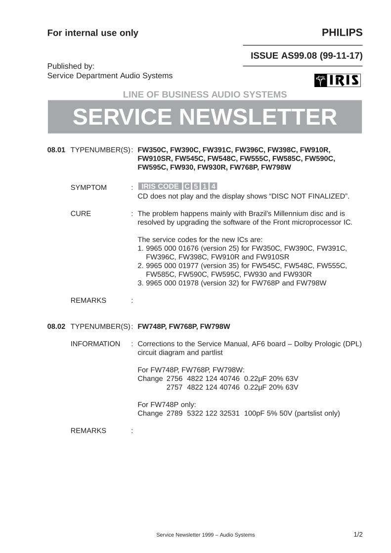
08.01 TYPENUMBER(S): FW350C, FW390C, FW391C, FW396C, FW398C, FW910R,FW910SR, FW545C, FW548C, FW555C, FW585C, FW590C,FW595C, FW930, FW930R, FW768P, FW798W
SYMPTOM :CD does not play and the display shows “DISC NOT FINALIZED”.
CURE : The problem happens mainly with Brazil’s Millennium disc and isresolved by upgrading the software of the Front microprocessor IC.
The service codes for the new ICs are:1. 9965 000 01676 (version 25) for FW350C, FW390C, FW391C,
FW396C, FW398C, FW910R and FW910SR2. 9965 000 01977 (version 35) for FW545C, FW548C, FW555C,
FW585C, FW590C, FW595C, FW930 and FW930R3. 9965 000 01978 (version 32) for FW768P and FW798W
REMARKS :
08.02 TYPENUMBER(S): FW748P, FW768P, FW798W
INFORMATION : Corrections to the Service Manual, AF6 board – Dolby Prologic (DPL)circuit diagram and partlist
For FW748P, FW768P, FW798W:Change 2756 4822 124 40746 0.22µF 20% 63V
2757 4822 124 40746 0.22µF 20% 63V
For FW748P only:Change 2789 5322 122 32531 100pF 5% 50V (partslist only)
REMARKS :
415CIRIS CODE
SERVICE NEWSLETTER

08.03 TYPENUMBER(S): FW830C, FW840C, FW870C, FW878C, FW890P, FW898W
SYMPTOM :The set behaves strangely after switching it on via Standby button ormains supply re-connection. Strange behaviour includes:• Loss of Tuner preset stations or tuning grid returns to 9kHz
condition• When changing source to Tuner the set stalls for a few seconds and
may or may not switch to Tuner mode• CD carousel rotates or the CD tray moves outwards• Tape deck motors start to run or relay starts activation and the deck
starts engaging and disengaging• During this strange behaviour condition the set does not go into
demo mode
CURE : The problem is caused by corrupted data being written into theEEPROM IC 7417 via the I2C_DATA line. The data corruption can beverified and cleared by performing an “EEPROM Format Test” in theService Test Program.
The problem can be solved by the following hardware modification onthe front board:1. Ensure (change if necessary) that resistor 3596 is 68Ω
(4822 117 12521)2. Change resistor 3611 to 4.7kΩ (4822 051 20472)3. Remove SMD jumper 44554. Add resistor 1kΩ (4822 050 11002) with insulated leads between
pin 37 of microprocessor IC 7413 and junction of resistors 3611and 3613 (left solder pad of jumper 4455)
REMARKS :
1k
1
3
2
4
Portion of the Front board (copper side view)
Eeprom connection to the Microprocessor IC
10K
3612
10K
3634
2474 1u
3613
1K
5403
2u2
4VSS
ST24C01B67417
E01
E12
E23
MODE|WC_7
SCL6
SDA5
VCC
8
3614
1K
+5V6
+5V6
4K7
3611
21
7413TMP87CH74
37
36
I2C_DATA
I2C_CLK
68R
3596
3597
1K
3
4Microprocessor IC
Add resistor 1k
Delete jumper 4455
071MIRIS CODE
Service Newsletter 1999 – Audio Systems 2/2

For internal use only PHILIPS
ISSUE PA99.04 (99-10-13)Published by:Service Department Portable Audio
LINE OF BUSINESS PORTABLE AUDIO
04.01 TYPENUMBER(S): AJ3290
INFORMATION : The Clock set button can get stuck inside when too much force isapplied on the button. A rib will be added on the top cabinet asstopper.
REMARKS : Modification will be implemented in production from week 9948onwards.
04.02 TYPENUMBER(S): AJ3940
INFORMATION : Additional information to Service Newsletter PA99.02.04.The transformer hum can be further reduced by adding 2 pieces ofsponge (about 20x15x2mm) between transformer and shield plate.
REMARKS : Modification has been implemented in production from week 9902onwards.
04.03 TYPENUMBER(S): AZ1010
INFORMATION : On special request the following parts were added to the servicepartslist:
pos code number article description––––––––––––––––––––––––––––––––––––––––––––––507 3103 307 96350 button set CD1 lacquered511 3103 307 96360 button set CD2 lacquered
REMARKS :
04.04 TYPENUMBER(S): AZ2000, AZ2010
INFORMATION : On the rear cabinet, the ribs for holding the Battery Spring (item 459)are broken. In order to strengthen the ribs their wall thickness wasincreased and a radius was added.
REMARKS : Modification has been implemented in production from week 9934onwards.
SERVICE NEWSLETTER
Service Newsletter 1999 – Portable Audio 1/3

04.05 TYPENUMBER(S) : AZ2750, AZ2755
SYMPTOM :Abnormal noise is audible in TAPE mode.
CURE : The signal paths on the Recorder board are too close.Solution is to cut 2 copper tracks on the printed board and to connectresistor 3729 and capacitor 2736 with a wire (for details see diagrambelow).
REMARKS : Modification has been implemented in production from week 9922onwards.This information will be followed by Service Information A99-577(3140 785 22030).
3075. 5
3140 113 307558240 051 18595
7711
2746
2744
7712
2750
2734
Recorder Board - Layout Diagram(PCB code : 3140 113 30755)
(1)
(3)
(2)
X41CIRIS CODE
Service Newsletter 1999 – Portable Audio 2/3

04.06 TYPENUMBER(S): AZ2750
INFORMATION : In course of production the source selection IC TC9145 (pos. U1) hasbeen replaced by the new type PT233 (9655 000 01767).Schematic and layout diagram of the Main Board had to be adaptedaccordingly. The new diagrams can be found in Service InformationA99-577 (3140 785 22030).
REMARKS : The new IC is used in production from week 9938 onwards withfactory change code KZ02.
04.07 TYPENUMBER(S): AZ7495, AZ7595, AZ7794, AZ7894
INFORMATION : Correction to Service Manual, Accessories:The code number for the External Battery Box “AY3770” should read4822 256 10592.
REMARKS :
Service Newsletter 1999 – Portable Audio 3/3

Service Newsletter 1999 – Audio Systems 1/2
For internal use only PHILIPS
ISSUE AS99.07 (99-09-28)Published by:Service Department Audio Systems
LINE OF BUSINESS AUDIO SYSTEMS
07.01 TYPENUMBER(S): FW350C/34, FW390C/34, FW398C/34
SYMPTOM :FM1 range is lost when the set is switched off.
CURE : The FM1 range (65.81-74MHz) can be turned on via the procedurepublished in Service Newsletter AS99.05.03.
However, due to a software problem, some sets disable the FM1range again when the set is switched off.
The problem can be resolved by replacing the microprocessor by thenew version “23”. The ordering code reads 9965 000 01676.
REMARKS :
07.02 TYPENUMBER(S): FW754P, FW765P, FW795W
INFORMATION : Corrections to the Service Manual, partslist
1. Service code for Rucksack of “Power4 Module” should read:4822 256 10575 Rucksack 4 Channel
2. FW795W/37 only: Service code for item 224(Exploded view, page 14-2) should read:4822 454 13447 Orn Display DPL only for FW795W/37
REMARKS :
2121IRIS CODE
SERVICE NEWSLETTER

07.03 TYPENUMBER(S): MC115
INFORMATION : On special request the following parts were added to the servicepartslist:
pos code number article description––––––––––––––––––––––––––––––––––––––––506 3103 304 65290 button set “power”507 3103 304 65390 cap-IR508 3103 304 65280 button set + cap509 3103 304 65310 button “surround”511 3103 304 65280 button set + cap512 3103 304 65300 button set “volume”
REMARKS :
07.04 TYPENUMBER(S): MC145
INFORMATION : On special request the following parts were added to the servicepartslist:
pos code number article description––––––––––––––––––––––––––––––––––––––––509 3103 304 66660 button set “power”511 3103 304 65390 cap-IR513 3103 304 66670 button set “volume”514 3103 304 66380 button set + cap514a 3103 304 66380 button set + cap516 3103 304 65310 button “surround”
REMARKS :
Service Newsletter 1999 – Audio Systems 2/2

Service Newsletter 1999 – Audio Systems 1/2
For internal use only PHILIPS
ISSUE AS99.06 (99-09-08)Published by:Service Department Audio Systems
LINE OF BUSINESS AUDIO SYSTEMS
06.01 TYPENUMBER(S): CD713, CD723, CD753
INFORMATION : Above mentioned sets use CD-Short Loader MK3.This module is equipped with CD-drive VAM1201 – 4822 691 10615.Based on repair feedback it has been found that sometimes theVAM1201 is replaced by CDM12.1 – 4822 691 30278.
Although drives seem to be identical, it is not allowed to replaceVAM1201 by CDM12.1. The higher clamping force of the CDM12.1might cause problems during open/close.
REMARKS :
06.02 TYPENUMBER(S): FW399V
SYMPTOM :Pictures skip and jump when playing a Video-CD.
CURE : The problem can be solved by the following modification on theServo Board:1. Add elcap 2861 22µF 16V (4822 124 41796) into the location
provided on the printed board2. Replace bare wire 9015 with resistor 3872 47Ω (4822 116 52195)
REMARKS :
06.03 TYPENUMBER(S): FW399V/21/21M
SYMPTOM :Sometimes the set does not read the TOC of some critical CDs.“NO DISC” is shown on the display.
CURE : The problem can be solved by the following modification on theMain Combi Board:1. Delete elcap 2342 100µF 10V
REMARKS : Above modification is implemented in production from week 9932onwards.
X15CIRIS CODE
X531IRIS CODE
SERVICE NEWSLETTER

06.04 TYPENUMBER(S): FW850C, FW855C, FW860P, FW880P, FW880W
SYMPTOM :Program number is not displayed for Tuner frequency 100.2MHz.
CURE : The problem is caused by software. Although the program number isnot displayed, the program number can still be selected.An improved software (version 26) for microprocesssor IC 7461TMP87CS71F is available via service code 4822 900 11253.
REMARKS :
X311IRIS CODE
Service Newsletter 1999 – Audio Systems 2/2

For internal use only PHILIPS
ISSUE AS99.05 (99-08-10)Published by:Service Department Audio Systems
LINE OF BUSINESS AUDIO SYSTEMS
05.01 TYPENUMBER(S): AS670/34, AS675/34
SYMPTOM :In standby mode, the clock display is switched off after a while.
CURE : There is nothing wrong with the set.Switching off the display is part of the “Lower Power StandbyFeature”, described in chapter 11 of the Service Manual.
REMARKS :
05.02 TYPENUMBER(S): CDC775
INFORMATION : From production week 9930 onwards a new microprocessor (mask 2)has been introduced:
pos. service code article description––––––––––––––––––––––––––––––––––––––––––––––––––––––7401 3139 110 51260 TMP87CP71F with marking “775S52161”
The new µP solves CD-Recorder related problems and reduces theFTD brightness to the level of other products from the Home Cinemarange.
The introduction of the new microprocessor is accompanied by somehardware changes on the DAC/AF-board.
The following components have been added:
pos. service code article description––––––––––––––––––––––––––––––––––––––––––––––––––––––3963 4822 051 20479 47Ω 5% 0.1W3975 4822 116 52176 10Ω 5% 1/6W9919 Bare Wire
REMARKS : For location of components see circuit diagram and componentlayout. New components have already been foreseen in thesedrawings, but were not used, yet.
X313IRIS CODE
SERVICE NEWSLETTER
Service Newsletter 1999 – Audio Systems 1/3

05.03 TYPENUMBER(S): FW350C/34, FW390C/34, FW398C/34, FW545C/34, FW548C/34,FW590C/34, FW768P/34, FW830C/34, FW878C/34, FW898W/34,MZ7/34
SYMPTOM :FM 65.81-74MHz cannot be tuned on the set
CURE : All Mini Systems 1999 versions /34 are set to the default FM range of87.5-108MHz when leaving the factory.
The lower FM1 range of 65.81-74MHz can be turned on by holdingthe undermentioned keys depressed, while switching on the mainssupply:
a) “Tuner” & “Search Up” for all models except the MZ7/34b) “Tuner” & “Next” for MZ7/34 only
The display shows “FM1 ON”.
REMARKS : By repeating the procedure the FM1 range will be switched off again.
05.04 TYPENUMBER(S): FW399V
INFORMATION : Service Manual, correction/update of the partslist
1) In the parts list of page 12-8 the service code for item 7202,IC AT27C020-12PC, should read 3139 110 52240 instead of8239 210 51830.
2) The following parts of the Loudspeaker Box are now available asservice spareparts:
service code article description–––––––––––––––––––––––––––––––––––––––9965 000 00757 TWEETER9965 000 00758 WOOFER9965 000 00795 BUZZER W/WIRE ASSY4822 464 10523 CLOTH FRAME ASSY
REMARKS :
X121IRIS CODE
Service Newsletter 1999 – Audio Systems 2/3

05.05 TYPENUMBER(S): FR960, FR970, MX975D
INFORMATION : Correction to the Service Manual, Electrical partslistMonobard FR960 (page 13-4) and Monobard FR970 (page 14-4)
The following items should read:
pos. service code article description–––––––––––––––––––––––––––––––––––––––3587 4822 051 20392 3.9kΩ 5% 0.1W3588 4822 116 52276 3.9kΩ 5% 0.5W3593 4822 051 20472 4.7kΩ 5% 0.1W3594 4822 051 20472 4.7kΩ 5% 0.1W3597 4822 116 52289 5.6kΩ 5% 1/6W3598 4822 116 52289 5.6kΩ 5% 1/6W
REMARKS : Electrical diagram is correct (page 10-4).
05.06 TYPENUMBER(S): FR970
INFORMATION : Correction to the Service Manual, Exploded View Partslist (page 12)The service codenumber for item 14 should read:3104 217 52260 “Window Display” only for FR970/01B/173104 217 52660 “Window Display” only for FR970/01
REMARKS :
05.07 TYPENUMBER(S): MC165, MC175
INFORMATION : Correction to the Service Manual, Electrical partslistThe service codenumbers of the Mains Transformers have beenmixed up. They should read:4822 146 11104 for /01 and /11 versions4822 146 11105 for /02, /05, /10 and /14 versions4822 146 11106 for /37 version
REMARKS :
Service Newsletter 1999 – Audio Systems 3/3

For internal use only PHILIPS
ISSUE PA99.03 (99-08-03)Published by:Service Department Portable Audio
LINE OF BUSINESS PORTABLE AUDIO
03.01 TYPENUMBER(S): GENERAL
INFORMATION : Service Information A99-572 (3140 785 22022) is published tointroduce the survey of service spareparts for those typenumbers incategory 1, for which no Service Manual has been published.
In this additional issue, the following typenumbers are new:Portable radio : AE2180, AE6776, AE6780Clock radio : AJ3141, AJ3142, AJ3143, AJ3144, AJ3145Radio Cass. Recorder : AQ4150/..S, AQ5150/..SHeadphone Stereo : AQ6411, AQ6412, AQ6413, AQ6414, AQ6682
REMARKS :
03.02 TYPENUMBER(S): AZ1120
INFORMATION : In course of production, the following parts have been changed toimprove DBB performance:• Capacitor 2503 and 2504 changed to 68nF (5322 121 42465)
REMARKS : Modification has been implemented in production from week 9921onwards.
03.03 TYPENUMBER(S) : AZ2000, AZ2010
SYMPTOM :Sets are not working on some batteries (e.g. Energizer batteries)because the battery plate fails to contact with the batteries.
CURE : The cabinet wall holding the battery plate is too thick.The simplest service solution is to add a washer (of 0.5 - 0.7mmthickness) behind the battery plate to compensate the tolerance.On long term, the battery plate will be modified to increase the heightof the contact point.
REMARKS : Modification has been implemented in production from week 9926onwards.
3112IRIS CODE
SERVICE NEWSLETTER
Service Newsletter 1999 – Portable Audio 1/3

03.04 TYPENUMBER(S): AZ2402, AZ2407
SYMPTOM :No FM reception at the higher end frequencies of the FM-band, whenVolume is set to maximum and MODE button is pressed.
CURE : Problem can be solved by changing following parts:• Capacitor 2322 and 2326 changed to 22µF (4822 124 81151)• Resistor 3223 changed to 150Ω (4822 116 83868)
REMARKS : Modification has been implemented in production from week 9923onwards.
03.05 TYPENUMBER(S): AZ2402
SYMPTOM :The Power ON/OFF switch 1496 or resistor 3594 is burst due to hightransient current.
CURE : Additional to Service Newsletter PA99.02.11, on long term the layoutof the Front board will be modified and following parts will be changedor added:• Resistor 3456 changed to 15kΩ (4822 116 52244)• Resistor 3457 changed to 5.6kΩ (4822 116 52289)• Resistor 3516, 47Ω (4822 116 52195) added• Diode 7483 and 7484, 1N4148 (4822 130 30621) added
REMARKS : Modification will be implemented in production from week 9932onwards.This information will be followed by Service Information A99-573(3140 785 22023).
03.06 TYPENUMBER(S): AZ2407
SYMPTOM :The Power ON/OFF switch 1496 or resistor 3594 is burst due to hightransient current.
CURE : Additional to Service Newsletter PA99.02.11, on long term the layoutof the Front board will be modified and following parts will be changedor added:• Resistor 3456 changed to 15kΩ (4822 116 52244)• Resistor 3457 changed to 5.6kΩ (4822 116 52289)• Resistor 3516, 47Ω (4822 116 52195) added• Diode 7482 and 7483, 1N4148 (4822 130 30621) added
REMARKS : Modification will be implemented in production from week 9932onwards.This information will be followed by Service Information A99-574(3140 785 22024).
X116IRIS CODE
X116IRIS CODE
212CIRIS CODE
Service Newsletter 1999 – Portable Audio 2/3

03.07 TYPENUMBER(S): AZ7381, AZ7382, AZ7383, AZ7481, AZ7482, AZ7483
INFORMATION : In course of production, the PCB Assembly was changed to PB2 (fordetails please refer to Service Manual 4822 725 26021).In the PB2 assembly a smaller headphone jack was used and thusthe hole for h/p jack on the cabinet was also made smaller.The cabinet (4822 449 80201) of the sets produced in earlier stage isno longer available and the new cabinet (4822 449 80266) withsmaller jack hole will be delivered as substitute.
As a service solution, for repairing sets with bigger headphone jack,we suggest to enlarge the hole by use of files (see drawing below).
REMARKS :
03.08 TYPENUMBER(S): MC165, MC175
INFORMATION : Correction to the Service Manual, Electrical partslistThe service codenumbers of the Mains Transformers have beenmixed up. They should read:
4822 146 11104 for /01 and /11 versions4822 146 11105 for /02, /05, /10 and /14 versions4822 146 11106 for /37 version
REMARKS :
0.25mm
0.45mm
0.45mm
ROUND FILE
FLAT FILE
Service Newsletter 1999 – Portable Audio 3/3

For internal use only PHILIPS
ISSUE AS99.04 (99-07-29)Published by:Service Department Audio Systems
LINE OF BUSINESS AUDIO SYSTEMS
This newsletter concerns the introduction of the new generation CD recorders.
First of all some issues concerning the new products are presented then the typical newfeatures in 1999 sets and explained, at the end the service approach is given accordingnext schedule:
• Introduction• The 1999 range overview• The 1999 products• User interface / interaction• What is new in all 1999 sets• Survey of ReWritable(disc) Compatible products in 1999• Survey of digital out products in 1999• CD-R(W) Digital Audio discs• Service approach
SERVICE NEWSLETTER
Service Newsletter 1999 – Audio Systems 1/1

,QWURGXFWLRQ
The 3rd generation CD Recorders have great similarity to the current 1998
range which was based on 3 concepts. First, the high-end CDR880 with a
neutral styling to match the installed base of HiFi components of any brand.
Secondly, a new styling for the CDR765 and CDR760 to match the Philips CD
player line, and thirdly, the separate Mini CDR560/CDR538 to address the
Mini systems market.
5DQJHRYHUYLHZWDEOHRIVWURNHYHUVLRQV
Product line-up 1999:
CDR 775
CDR 770
CDR 570
Double deck
Single deck
Mini deck
CDR 950 Top quality deck
CDR 765
CDR 760
CDR 560
CDR 880
'LIIHUHQFHEHWZHHQVWURNHYHUVLRQV
CDR TYPE Europe AP/ Latam Japan Korea Eastern
Europe
USA
950 /00 /01 /06 /13 /14 /17
775 /00 /01 /06 /13 /14 /17
770 /00 /01 /06 /13 /14 /17
570 /00 /01 /06 /13 /14 /17
930 /00 /01 /06 /13 /14 /17
951 /00
776 /00

3RZHUVXSSOLHV
West Europe
/00
USA /17 Asia Pacific
/01
E & C Europe /14 Japan /06 Korea /13
CDR950 230V +/-10% 50
Hz
117V +/-10% 60
Hz
100/110/220/230
V
+/-10%
230V +/-10% 50
Hz
100V +/-10% 60
Hz
230V +/-10%
50 Hz
CDR775 80-276V 50-60
Hz
80-150V 50-60
Hz
80-276V 50-60
Hz
80-276V 50-60 Hz 80-276V 50-60
Hz
80-276V 50-60
Hz
CDR770 80-276V 50-60
Hz
80-150V 50-60
Hz
80-276V 50-60
Hz
80-276V 50-60 Hz 80-276V 50-60
Hz
80-276V 50-60
Hz
CDR570 80-276V 50-60
Hz
80-150V +/-10%
50-60 Hz
80-276V 50-60
Hz
80-276V 50-60 Hz 80-276V 50-60
Hz
80-276V 50-60
Hz
CDR930 80-276V 50-60
Hz
80-150V +/-10%
50-60 Hz
80-276V 50-60
Hz
80-276V 50-60 Hz 80-276V 50-60
Hz
80-276V 50-60
Hz
+LJKHQG&'5
After being very successful with both the CDR870 and CDR880, we have
seen the competition enter the market for high-end CD Recorders. Philips will
join this market with the CDR950, which will have the Harmonised Design
styling, matching other products like the new DVD player, receiver and CD
players in 1999. To make the 950 into a serious player in the segment, it will
be equipped with high-end specifications for both recording and playback.
Together with a maximum of dazzling new features like text editing, this model
will be marketed as our ‘Flagship’ of the range at a target price point of DM
999.-.
3URGXFWVSHFLILFIHDWXUHRYHUYLHZ&'5
Successor of CDR880 with e.g. :
Analogue linear power supply (Less Hum & Noise)
SRC & DLR (Direct Line Recording)
High-quality cables
New in 1999:
Harmonised Design (Receivers / CD changer / DVD / VCR)
Fade-in / fade-out (with adjustable timing 10 seconds)
Stereo microphone input (separate or mixed recording with separate level
potmeter)
Monitor path (listen to the actual recording or using the SRC for separate)
High-end audio specifications(separate AD / DA converters)
Input / output as CDR880 but with 2 digital coaxial inputs
Renaming the inputs (e.g. change DIGITAL 1 into ‘MY DAT RECORDER’
'XDOGHFN&'5
To continue the success of the current dual-deck CDR765, its successor the
CDR775 will surprise you with many new features like the menu-controlled
user interface via an easy jog control, text recording and a standby function.
The design matches the Audio Systems CD players, but shows significant
improvements in many details.
3URGXFWVSHFLILFIHDWXUHRYHUYLHZ&'5&'5
Successor of CDR765 with e.g.:
Double-speed recording (internal)
Seamless playback changer
DJ mode (separate play / outputs)
Recording from internal or external sources
Synchronised start recording from external sources
New in 1999:
CD Text recording from internal deck
Normal-speed recording whole disc (Listen mode)
Advanced and easy programming of favourite tracks
(e.g. a program that does not fit can be edited (adding and/or deleting tracks).
Random programming over two discs (CDR765 can only program per disc)
New CD drive in the dual-deck recorder which also offers more functionality
(better performance, playing unfinalised discs)
CD drive is able to play unfinalised CDR/RW discs
SRC (11-56 kHz)
DLR (Direct Line Recording)
6LQJOHGHFN&'5
The CDR760 will be succeeded by the CDR770, which also benefits from the
new featuring of text editing, easy jog and the new user interface. The design
also matches that of the Audio Systems CD players.
*) All these models are planned in Black and Champagne versions

3URGXFWVSHFLILFIHDWXUHRYHUYLHZ&'5
Successor of the CDR 760 with e.g.:
Synchronised start recording of DISC
or TRACK
Digital optical, digital coaxial and
analogue inputs
Digital coaxial and analogue outputs
New in 1999:
SRC (11-56 kHz)
Direct Line Recording
CD Text input/editing
Multi-track erase (RW)
Scrolling text
Synchronised start of disc recording automatically followed by auto finalise
(made CD).
0LQL&'5HFRUGHU&'5
To complete the range for 1999, the CDR560 will be succeeded by the
CDR570, which has the same specification as the CDR770. The design
remains the same on the outside to match the current Mini Systems, with the
exception of the new easy jog control and the menu-controlled user interface.
3URGXFWVSHFLILFIHDWXUHRYHUYLHZ&'5
Successor of CDR560 with e.g.:
System remote control for CDR930
New in 1999:
Similar featuring to CDR770 but no headphone
output
Matching the FW930C design
CDR MINI CD RECORDER
OPEN/CLOSEEASY JOG
ENTER
REWIND
RECORDREC TYPE
MENU
ERASE
SOURCE
CANCEL
PLAY/PAUSE STOP
FFWD
ERASE FINALIZE
SCROLL DISPLAY
ON/OFF
Recordable
DIGITALOPTICALANALOG
II
CDSYNC
PROGRAM
SHUFFLE REPEATSCAN
ALL
MANUAL
TRACK
RW
REMTRACK
REC TIMEREMTOTAL
TIMESTEP
TRACK
1 2 3 4 5 6 7 8 9 10 11

0LQLV\VWHPVZLWK&'5):):
Two mini systems will be created with a bundled CDR.
The CDR930 will be created for bundling together with the FW930 Mini
System and the FW910.
,PSURYHGXVHULQWHUIDFH,QWHUDFWLRQ
*HQHUDO
The aim for CD-R is to make successful CD recording so easy that users can
easily remember all the steps needed to create and play their own CDs. This
is where user interface design plays a crucial role. Making a recording on CD
is a technically complex task for the CD Recorder, but the trick is to keep this
complexity away from the user. When the task of recording is analysed, there
are very few things that the user has to know and do to make a successful
recording. So what are the essential aspects for achieving simple, user-
friendly operation?
The display is one of the most important. It constantly shows the status of the
CD Recorder and gives relevant information about the current task. It is able
to enter into a dialogue with the user, giving relevant information and choices
at the appropriate moments, warning and explaining problems when
necessary, and informing the user when the task will be complete. In other
words, the display gives all the elements of good customer service!
The controls are also important. The easy jog, in particular, makes controlling
the CD Recorder quicker and more intuitive by rolling through the tracks of a
CD or the choice and selection of tasks.
The 3rd generation of CD Recorders will address a larger, and to some extent
less ‘audio-involved’, target group compared with the previous models. This
requires a more self-explanatory and consistent user interface.
Together with specialists in the field of Ergonomics and Interactive Design, a
new, more self-explanatory, user interface has been designed.
The CD-R is designed to communicate with us as humans. That’s when
making your own CD becomes absolute simplicity!

:KDWEHQHILWVGRHVLWRIIHU"
1) Reduction of nuisance calls. The set will more explicitly show the consumer
what was done wrong or what he should do next.
2) Improved ease of use (also the double deck).
3) A very satisfied consumer and a competitive edge versus the competition.
4) Sales force will be able to operate all types of Philips CD Recorders (and
Mini sets) as we now follow a similar approach throughout the audio
organisation.
:K\GR\RXQHHGLW"
To make issues like Finalising, Unfinalising, Initialising (OPC), Erasing only
CD-RW, CD Text (text memory), all the different status & types of discs, as
well as the feedback given on the display, clearer and more explicit at the
moment you need to know it.
+RZGRHVLWZRUN"RQO\WKHPDMRUFKDQJHVDUHGHVFULEHG
n One RECORD key to start all types of recording (inclusive Finalising and
Erasing)
n One REC-TYPE key which displays clearly what recording (-standby) is
selected and which is the next key that should be pressed to start.
n Easy jog control for quick and accurate track selection.
n Standby via remote control. Hard On/Off key on front that ‘wakes’ set in
standby. This is very nice when using the CD-R in a stack (e.g. power
taken from a receiver). If the receiver is switched on, the CD-R will be in
standby unless a CD-R key is touched (RC or front).
n Clear and more functional messages.
n Technical names like CD-SYNC-1 have also been renamed to ‘RECORD
TRACK’ or ‘MAKE CD’ when recording with CD-SYNC & FINALISE.
n All typical CD functions are available on the front (FWD, BWD, repeat,
shuffle, program, scroll)
n Menu access like text input is possible via both remote control and front
panel.
n Synchronised start (analogue and digital) is active as standard (no choice
needed).

n Scanning (CDR765) is no longer needed.
n Clear status information from the newly designed FTD. (See below):
n Trackbar that clearly shows the tracks on the disc and what track is
active or selected.
n Disc label shows clearly if a disc is in the tray.
n Status of set, play, pause, rec.
n The play modes like ‘Changer’ and ‘DJ-mode’ are clearly visual.
n Input selection (internal / external) continuously visual.
n Advanced programming (in STOP mode as well as REC standby)
The display shows an example in program mode:
Left: The remaining recording time is available so the user can judge if the
selection will fit on the blank CD.
Middle: When searching a new track to be programmed, it already shows the
total amount of time before selecting it.
Right: The number of tracks in the program (steps),
The track bar shows which tracks are programmed.

5HPRWHFRQWURO
With its ergonomic design this new RC enables users to
carry out all the necessary control actions from the comfort of
their armchair.
For the 1999 range, one remote control will be supplied for
both single- and dual-deck recorders. As well as Philips CD
Recorders, this remote control can also be used with all
Philips CD players by selecting ‘CD’. To avoid damaging the
disc recording process, no Recording Finalise and Erase
keys are provided.
)XQFWLRQVZKLFKFDQRQO\EHDFWLYDWHGYLDWKHUHPRWH
FRQWURO
- Intro scan function (scanning tracks 10 seconds).
- Switching the recorder into low-power (<6 watt) standby
mode.
- Manual writing of a new track number
:KDWLVGLIIHUHQWYHUVXV"
From the remote control, it is also possible to control the complete menu
using the additional menu keys. (The next / previous keys are used as the
easy jog.)
Text input is new and works in the well known way, similar to cellular phones
(Handy, GSM).
* planned in black and champagne for CDR950/CDR951

:KDW¶VQHZLQDOOWKHVHWV"
• Audio buffer
• CD Text input, recording & editing (album / artist for disc and per track; 60
char.)
• Text scrolling (possibility to display this permanently for dealers and freaks)
• CD Text input via front panel and remote control
• Tray blocking mode to avoid theft of discs on the shop floor - dealer feature
• CD Recorder drive offering more functionality, e.g. CD Text, audio buffer,
integration of functions
• Auto finalise CD-R/RW (Make CD!) and Auto unfinalise CD-RW (To avoid
ERASE TOC)
• Synchronised start of recording also from ANALOGUE sources
• Digital recording level adjustment and balance setting to correct for
differences in volume level between source discs
• Multi-track erase
• Sample Rate Converter 11-56 kHz (DAB = 32 kHz; DAT = 48 kHz)
• All sets have the high performance DLR technique (Direct Line Recording)
• Music scan or Intro scan 10 sec. (program, disc)
• Improved stop modes (digital and analogue)
• Standby (RC) + hard on/off
• Easy jog (menu controller / level controller / next-previous)
• New user-friendly user interface:
– music calendar (track bar)
– FTD with fundamental status of the set visual
– advanced programming (99 tracks / reviewing and editing programs)
– easy start of recording
– clear messages show customer what to do next
• Improved finishing (face value)
• Remote control functionality
• HD-CD recording (No playback)

$8',2%8))(5
With the new DASP processing IC we are able to introduce an advanced
audio buffer with a capacity of several seconds (0-3 sec.).
Although this is not a major competitive edge compared with the competition
(audio buffer is quite common), it gives a major improvement over our 1998
range CD Recorders.
:KDWGRHVLWPHDQIRU\RXUUHFRUGLQJ"
n No loss of music while starting a recording with synchronised start (CD
Sync). At present* a maximum of 400 msec. can be lost.
n Synchronised start per track. At present* this is not included because the
first track only of an original CD usually starts after a couple of seconds.
The other tracks often start immediately. Losing 400 ms per track is
unacceptable.
n No loss of music when recording from a program. A program jumps
immediately to a track, and the missing 400 ms can be noticed by a critical
consumer.
n Perfect positioning when jumping to next / previous track. Track increment
will be positioned in exactly the same position as the original. At present*
the track increment is delayed by 3 frames (13 ms). Jumping can only be
done to a position that is shifted by 39 ms into the new track.
n Synchronised start analogue.
n Better stop behaviour analogue.
n Recording can be stopped within 3 seconds without ‘damaging’ the CD. At
present* a track of 4 seconds will always be recorded.
n When entering an SCMS track, no recording will be made of the first few
seconds. At present* a track of 4 seconds will be recorded.
* ‘At present’ refers to the 1997/1998 product range.

BUFFER 3 seconds
Input StageDigital orAnalogue
DISC
Output StageDigital or Analogue
:K\GR\RXQHHGLW"
First of all: to make perfect recordings without any loss of music at the start of
a track. Secondly: all information available on the original disc will be
duplicated at the exact same spot of the disc you are recording to. By using
this state-of-the-art technology, we have finally perfected the ‘bit-for-bit’
copying technique.
+RZGRHVLWZRUN"
The audio (and track information) will pass through an audio buffer that
continuously holds several seconds (0 to 3 seconds) in memory. In this way
the recorder has enough time to determine the status of the input signal
(music versus no music, track increment, lead-out etc.), and will start the
recording at the right moment. The music is taken from the buffer.
,PSURYHG6723PRGHV
The current range (without audio buffer) has difficulties in detecting if the
source has stopped. With the audio buffer this is no longer a problem, and
provided the opportunity to improve the stop behaviour.
:KDWLVWKHEHQHILW"
Perfect stopping of recordings (even when an analogue source is used as
input).

:K\GR\RXQHHGLW"7RDYRLG
n 20 seconds silence between recordings (current range)
n The recorder stopping when recording music with very silent parts (e.g.
playing a violin)
n The possibility to stop a recording which has just started (within 3 seconds),
without having anything recorded on the disc
n To be able to record properly from CD changers
+RZGRHVLWZRUN"
See audio buffer.
$QDORJXH&'6\QF
:KDWLVWKHEHQHILW"
Synchronised start of a recording with an analogue source or a professional
source without subcode information as input.
:K\GR\RXQHHGLW"
Synchronised start of a recording ensures that the recorder will only start
when music is detected.
+RZGRHVLWZRUN"
Digital information also contains the track start information. This information is
used to start a digital recording.
This kind of information is not available for analogue input signals. In this
case, the input level is continuously measured with the help of the audio
buffer. When the source has started, the recorder senses a significant change
in the input level and starts recording (input level above -50dB). As the first
seconds are still in memory (audio buffer), the recorder will calculate a certain
time back in time and put this audio data on the disc. We called a virtual start
point.

Track X Track X+1
A
B
A
CD C
B
/HYHO
G%
WLPH
Explanation :
0 Auto start active
1 Track transition is detected when audio goes above value A
2 The actual recording of the audio track will start at point 2. A jump
backwards is performed in the audio buffer” Time C” . Virtual start point
3 & 4 when audio goes below level B for a time D, a track increment is
detected
5. When audio rises again above value A
6. The recording of the new audio track will start at point 6

6DPSOH5DWH&RQYHUWHU65&
:KDWLVWKHEHQHILW"
Recordings can be made from all kinds of digital sources (with sampling
frequencies from 12 kHz - 56 kHz).
:K\GR\RXQHHGLW"
• When you want to record from a source with a sampling frequency that is
not equal to the 44.1 kHz as used in CD and MD. The sampling rates of the
various digital sources are:
– CD 44.1 kHz
– MD (digital recordings) 44.1 kHz
– MD (analogue recordings) 44.1 kHz
– DAB (Digital audio broadcasting) 32 /48 kHz
– DAT 32 / 44.1 /48 kHz
– DCC 44.1 / 48 kHz
• When you want to record from pitch-controlled sources (variable Sample
Rate Converter)
+RZGRHVLWZRUN"
The input signal is sampled again with a frequency of 70 MHz and
reconstructed to give a signal with frequency of 44.1 kHz.

'LUHFW/LQH5HFRUGLQJ'/5
For the perfectionists among audio enthusiasts, Philips has added a
technique to make true ‘bit-for-bit’ recordings from sources with a Sample
Rate Frequency of 44.1 kHz +/- 100 ppm (CD and MD).
For more detailed information, see the below.
'LUHFW/LQHUHFRUGLQJ'/5
7KHUHDUHWZRSXUSRVHVIRUGLUHFWOLQHUHFRUGLQJ
7KHILUVWRQHLVWRPDNHDELWWRELWFRS\ZLWKRXWFKDQJLQJWKHELWVRIWKHRULJLQDOGLJLWDO
VRXUFH+RZGRHVWKLVZRUNLQWKH&'5"
&RQQHFWHGWRDGLJLWDOVRXUFHRIDVDPSOHUDWHIURPN+]SSPWKHPDFKLQH
ZLOODXWRPDWLFDOO\WXQHKLVFU\VWDOLQWKHVDPHGHYLDWLRQ7KHVSHHGRIWKHUHFRUGHUZLOO
IROORZWKHVSHHGRIWKHFRQQHFWHGVRXUFH1RZZHDUHPDNLQJDGLUHFWOLQHUHFRUGLQJ
%LWWR%LWFRS\7KLVKRZHYHUKDVLW¶VOLPLWV7KHDFFXUDF\RIWKHFRQQHFWHGGLJLWDO
VRXUFHPXVWEHZLWKLQWKHUDQJHRISSPSLHFHSHUPLOOLRQ,IWKHVRXUFH
H[FHHGVWKHGHYLDWLRQRISSPWKHUHFRUGHUZLOODXWRPDWLFDOO\VZLWFKRYHUWR
6DPSOH5DWH&RQYHUVLRQ'XULQJDUHFRUGLQJLWZLOOQHYHUFKDQJHEDFNWR'LUHFW/LQH
5HFRUGLQJWRDYRLGXQGHVLUDEOHFOLFNVLQWKHDXGLRVLJQDO
7KHVHFRQGUHDVRQLVWRHOLPLQDWHWKHMLWWHURIWKHLQFRPLQJGLJLWDOVRXUFHGHMLWWHULQJ
,PDJLQHWKHVRXUFHLVZLWKLQWKHVWDQGDUGN+]SSPEXWWKHGHYLDWLRQLV
FKDQJLQJLQWRDYHU\KLJKIUHTXHQF\7KLVZLOOFDXVHH[WUDMLWWHULQWKHZULWHSDWWHUQRI
RXUUHFRUGHU$OVRWKHTXDOLW\RIWKHDXGLRZLOOEHDIIHFWHGE\WKLVMLWWHU7RSUHYHQWWKH
H[WUDMLWWHUDGHMLWWHUV\VWHPKDVEHHQLPSOHPHQWHGLQRXUNH\FRPSRQHQW7'$1
7KLVFRQYHUWVDOOMLWWHUFRPLQJIURPWKHFRQQHFWHGGLJLWDOVRXUFHLQWRDPD[LPXPRI
+]7KLVJLYHVWKHEHQHILWWKDWWKHµZULWLQJMLWWHU¶LVYHU\VWDEOH
:KDWLI\RXOLVWHQWRDFRS\RIDQRULJLQDODQGLWRFFXUVWKDW\RXKHDUDGLIIHUHQFH"
7KLVGHSHQGVWRWKHTXDOLW\RI\RXU&'SOD\HUDQGWKHTXDOLW\RI\RXURULJLQDOGLVF7KH
&'UHFRUGHUVIURP3KLOLSVPHHWWKHQHHGVRIWKHVWDQGDUGNQRZQDV63',)6RQ\
3KLOLSV'LJLWDO,QSXW)RUPDW(YHU\SOD\HUVKRXOGPHHWWKHUHTXLUHPHQWVLQWKHGLJLWDO
VWDQGDUGQRUP,(&,,,63',)WRVDIHJXDUGDJRRGGLJLWDOFRS\LQJEHKDYLRXU
In today’s situation, the CDR880 is the only CD Recorder from Philips which is
equipped with the high-performance DLR technique. In the 1999 range, we
will introduce DLR for all new models.

:KDWLVWKHEHQHILW"
∗ A perfect copy of the source material (44.1 kHz), meaning
a true ‘bit-for-bit’ recording.
∗ HD-CD Recording
:K\GR\RXQHHGLW"
To avoid digital information being transformed by the Sample Rate Converter.
Elimination of jitter from the incoming digital source (‘dejittering’). The result is
a clear reproduction of the original material.
+RZGRHVLWZRUN"
When a signal of 44.1 kHz is detected, the Sample Rate Converter is by-
passed and the digital bitstream is recorded directly to the destination disc.
To be able to make a ‘bit-for-bit’ copy, it is essential that the source disc has
the same speed as the destination disc.
We therefore measure the input frequency (speed of the source disc). A
tuneable crystal accurately controls the speed of the destination disc and
keeps the speed within the limits of max. +/-100 ppm (parts per million). If the
speed deviates too much, the Sample Rate Converter is activated.
To avoid audio disturbance, the recorder will never switch back to DLR during
a recording.
6RXUFH .K=
6DPSOH5DWH
&RYHUWHU
&'5'LVF
7XQHDEOH&U\VWDO
<HV
1R
<HV
1R

+'&'±UHFRUGLQJ
With a bit-for-bit DLR technology, HDCD-encoded CDs are recorded in HDCD
(High-Density Compact Disc) format. This means that if you copy an HDCD
disc using the digital output of your CD player, the entire encoding technology
is reproduced. This proves that DLR technology really does make a bit-for-bit
copy of a CD without interrupting the audio data.
CD players with a built –in HDCD filter can playback the higher sound quality
of these discs.
The new range of CD recorders do not have the HDCD filter and encoder
built-in. This means that the CD recorder cannot playback the HDCD quality.
:KDWDUHWKHEHQHILWV"
HDCD gives you a 20-bit dynamic range and a more natural instrumental
sound.
HDCD uses the same standard as a normal CD. You can play HDCD discs on
any CD player, anywhere in the world
:K\GR\RXQHHGLW"
If you have a CD player with an HDCD filter and DAC, then you playback the
recording without HDCD sound quality. (The recorder has no HDCD filter).
+RZGRHV+'&'ZRUN"
HDCD converts analogue signals (ADC) first to 192/176.4 kHz –24bit. Then,
decimation takes place from 196/176.4 kHz through 96/88.2 kHz to 44.1 kHz
– 24bit. After that, HDCD extended dynamic range encoding is performed,
which delivers a 44.1 kHz - 16bit signal (CD standard).
To allow detection of HDCD afterwards dithering is done which implements
the HDCD detection code.

:KDWLVWKHGLIIHUHQFHEHWZHHQ&'5&'5&'5DQG'/5LQ
&'5"
The CDR760 / 765 / 570 / 538 have no Sample Rate Converter to by-pass. So
these sets can only make digital recordings from sources with the 44.1 kHz
sampling frequency (CD and MD).
As (bad) sources could deviate by more than 150 ppm (the standard), we
have built-in a Voltage Controlled Oscillator (VCO) to keep the speed of the
destination disc within the limits of +/-100 ppm (+/-1%). This enables
recording from even very low-end CD players, but also increases the amount
of jitter.
The 1999 range has been designed with the optimal architecture: DLR (44.1
kHz +/-100 ppm) and SRC for signals that deviate too much for DLR.
(For a detailed description, see also DLR.)
,QLWLDOLVLQJ23&5XQQLQJ23&
Running OPC is a feature that ensures an optimal recording quality. It is
unique to Philips recording devices.
:KDWLVWKHEHQHILW"
- Maximum compatibility with other CD players and optimal recording quality
- High-quality writing on the blank CD-R(W)
:K\GR\RXQHHGLW"
CDs are often recorded for use in other CD players (e.g. car, portable CD,
sound machine etc.). This technique ensures maximum compatibility.
+RZGRHVLWZRUN"
Running OPC means that the optimal power for the laser is adjusted
continuously.
To ensure that the laser energy is constantly optimised during a recording, an
initial OPC (Optimum Power Calibration) is performed each time a disc is

DUST on the Disc surface
OPC
Value
Max. PowerPower
loaded, together with constant running OPCs which compensate for dust,
scratches and any other possible variations across the disc surface.
6&066HULDO&RS\0DQDJHPHQW6\VWHP
:KDWDUHWKHEHQHILWV"
SCMS is the function that prevents unauthorised copying by adding copy
inhibit information to the digital signals.
:K\GR\RXQHHGLW"
Unauthorised copying is restricted by law. All digital recording equipment for
consumer use must be equipped with SCMS.
+RZGRHVLWZRUN"
Originals that are subject to copyright protection (Copy Protected audio) are
marked by a copy bit which is present in the digital signal (EBU). This copy bit
is taken over and placed on the +RPHFRS\ every second.
SCMS distinguishes between three possible copying situations:
Original status: Copy bit status:
1. Copy Free originals ‘low’
2. Copy Protected audio (commercial CDs) ‘high’
3. Home copies ‘toggled every 65 ms
between ‘low’ and ‘high’

The (SCMS) only allows a new digital recording to be made under specific
conditions:
– A digital copy of Copy Protected audio becomes a +RPH&RS\ of Original
audio.
– A digital copy of a +RPH&RS\ of Original audio is not possible. Only an
analogue copy can be made!
– A digital copy of Not Copy Protected audio remains Not Copy Protected
audio.
– An analogue copy of any kind of audio becomes Copy Protected audio.
To find out if a CD is Copy Protected, all you need to do is just start the
recording as usual. If the CD is Copy Protected, the message ‘ COPY
PROTECT’ will be displayed.
In this case the recording can be made via the analogue connections (to be
selected using the SOURCE key) The CDR775 dual-deck recorder (copying
from internal CD deck Å CDR deck) will automatically switch over to
analogue if a Copy Protected original is detected.
Protected Audio
Home copy
Protected Audio
Digital recording
Analogue recording
(pre recorded oranalogue recorded disc)
Home copy
Digital recording

5,'5HFRUGHU8QLTXH,GHQWLILHU
:KDWDUHWKHEHQHILWV"
+RPH&RSLHV are marked with a unique code.
The RID is a method to prevent unauthorised copying by enabling
identification of the recorder on which a recording has been made.
:K\GR\RXQHHGLW"
In line with SCMS, the RID is required on consumer digital recording
equipment to allow identification of +RPH&RSLHV that may be made as the
result of illegal activities.
+RZGRHVLWZRUN"
The RID is a 97-bit code which is recorded every 100 frames (1.3 sec.) on all
discs made with the CD Recorder. It comprises a brand name identifier, a
type number and the drive number (e.g.: PH775xxxxxx) which, together,
uniquely identify the recorder on which any specific disc was recorded.
'LVDEOLQJRIWUD\GHDOHUIXQFWLRQ
:KDWDUHWKHEHQHILWV"
Extra safety feature for dealers who want to demonstrate the CD Recorder
permanently.
:K\GR\RXQHHGLW"
To prevent theft of discs used in demo players on the shop floor.
+RZGRHVLWZRUN"
By pressing a key combination (OPEN/CLOSE & STOP) during powering-up
the CD Recorder, the tray will be disabled (or enabled). This setting is stored
in the memory.

&'7H[WHGLWLQJUHFRUG LQSXWSOD\EDFN
The new CD Text feature offers users the option of identifying the disc while
playing. However, creative users will be able to find several other applications
for this feature (e.g. you can give personal names to songs, or if you have
recorded your own voice the ‘artist name’ can also show the performer’s
name).
*CDR775 only!
:KDWDUHWKHEHQHILWV"
1. PLAYBACK: Title and artist names of the disc and tracks appear on the
display.
2. INPUT: The disc/track titles and artist names can be added in the stop
mode or during recording, independently of the tracks being recorded.
3. RECORDING: CD Text is copied from the original, if not protected
(CDR775 only).
4. EDITING: Text can always be edited for a CD-RW disc, and this can also
be done for CD-R as long as the disc is NOT finalised.
:K\GR\RXQHHGLW"
1. To see title and artist information in the display during playing.
Tip: dealers can show this text feature permanently on the display.
2. To personalise your own recordings by giving them a name, e.g. DISC
TITLE: ‘MY FAVOURITE LOVE SONGS’.
Tip: dealers can make special discs with commercial texts like ‘I CAN
RECORD’ or ‘MAKE YOUR OWN CD’, combined with music or slogans to
scroll over the display during demo in the shop.
3. To avoid the need for manual text input.
4. To be able to change an existing text.
+RZGRHVLWZRUN"
Text input is easy, by using the menu plus the easy jog control or by using the
remote control.

The user can select the album title, artist title, track titles or track artists to
make a text of max. 60 characters. The text will be stored in the memory of
the CD Recorder until the disc is finalised. During finalising of the disc, the
text is written to the Table Of Contents (TOC).
As long as the disc is not finalised, the user is still able to change the text (for
both CD-R and CD-RW discs!).
For CD-RW discs, the text can always be changed.
&'7(;7,1387
Text input is very flexible and convenient:
The text menu is active in both STOP mode and RECORDING mode.
1. STOP mode: When a CD-R(W) disc with recorded audio tracks is in the
recorder, text for the recorded tracks can be added.
2. RECORDING mode: Text for 99 tracks can be added completely
independently of the track being recorded at that time. This also applies
even if the actual recording has not (yet) been made. When the recording
has stopped, the text for the recorded audio tracks will be stored. (If auto
finalise was active and the text input menu is still open, the auto finalise
function is disabled.)
7(;70(025<+$1'/,1*
As the CD Text is part of the Table Of Contents, all text will stay in the CD
Recorder’s memory until that disc is finalised. (The text can therefore still be
edited as long as the disc is not finalised.)
The memory can contain text for approximately 50 discs, each with 20 tracks.
(If only a disc title and artist name is used, text for more than 100 discs can be
stored.)
To prevent users from structurally not finalising discs, the recorder will show a
flashing message ‘UNFINALISED’ every time the tray opens, together with the
percentage of the memory which is used (TEXT MEMORY xx%).
&'7(;70(025<)8//
Although the memory capacity is more than sufficient, a MEMORY FULL
message may sometimes be displayed. The user then has two options: either

finalise a couple of discs, or delete the text for some discs. The stored text for
every unfinalised disc can be reviewed or deleted by using the menu
(MEMORY VIEW function).
&'/ORDGHU
The new generation of Philips CD Recorders use the latest recording
technologies. These ensure perfect recording quality.
:KDWDUHWKHEHQHILWV"
-Better and quicker jumps to a new track. Specially needed when you make a
program on your player.
-Possibility to record and play CD-Text
:K\GR\RXQHHGLW"
This new loader enables the CD Text function, and at the same time it solves
all the shortcomings of the current range.
+RZGRHVLWZRUN"
The new feature in our loader is PCS ( Position Control System)
With this new servo control system we can jump much quicker than the
previous one.
Fully compatible with the RED Book standard .
CD-text implementation for read and write options over the entire disc.
$XGLR&RGHF8'$761XVHGLQDOOVHWVH[FHSW&'5
This analogue-to-digital and digital-to-analogue converter has signal
processing features based on bitstream conversion technology.
The fully integrated analogue front end (including PGA and digital AGC) and
DSP featuring makes the device an excellent choice. The Codec has special
sound processing features in playback mode like de-emphasis, volume and
soft mutes.
6WHUHRN+]0XOWLELWVLJPDGHOWD'LJLWDO$QDORJXH&RQYHUWHU
&'5RQO\
The flagship CDR950 is equipped with the AD1855 (Analogue Devices), a
high-performance, single-chip stereo, audio DAC delivering 113 dB Dynamic
Range and SNR (A-weighted, not muted) at 48 kHz sampling rate. It
comprises a multibit sigma-delta modulator with dither, continuous time
analogue filters and analogue output driver circuitry. It is backwards-
compatible by supporting 50s/15s digital de-emphasis intended for ‘red-book’
44.1 kHz sampling frequency playback from compact discs.
The AD1855 accepts 16bit –bit serial audio data in MSB first, two-
complement format.
Summery of AD1855 features:
∗ Multibit Sigma-Delta Modulator with “perfect differential
linearity restoration” for reduced idle tones and noise floor.
∗ Data direct scrambling DAC-least sensitive to jitter
∗ Differential output for optimum performance 113 dB S/N
and dynamic range at 48 kHz sampling rate.
∗ -97 dB THD+N
∗ On-chip volume control with 1024 steps.
∗ 5V Stereo Audio DAC System
∗ Hardware and software controllable clickless mute
∗ Digital de-emphasis processing
%LWVLJPDGHOWD$QDORJXH'LJLWDO&RQYHUWHU&'5RQO\
The CDR950 uses the AD1877 (Analogue Devices), a stereo, 16-bit
oversampling ADC based on sigma delta technology intended primarily for
digital audio bandwidth applications .Each single-ended channel consists of a
fourth-order one-bit noise-shaping modulator and a digital decimation filter.
An on-chip voltage reference, stable over temperature and time, defines the
full scale range for both channels. Digital output data from both channels are
time-multiplexed to a single, flexible serial interface.

Summary of the AD1877 featuring:
∗ 92 dB (typ) dynamic range
∗ 5V power supply
∗ Single-ended dual-channel analogue inputs
∗ 90 dB (typ) S/(THD+N)
∗ 0.006 dB decimator passband ripple
∗ 4th order, 64-times oversampling sigma-delta modulator
∗ 3-stage, linear phase decimator
∗ On-chip voltage reference.
)DGHLQ)DGHRXW&'5RQO\
:KDWLVWKHEHQHILW"
Smooth start and stop of the audio signal when recording parts of music. This
is a more sophisticated recording feature.
:K\GR\RXQHHGLW"
When you want to make a recording where the start of end of the music is not
well defined (e.g. one song from a live concert, or a recording from the radio).
The alternative is to use the level potmeter or a special digital signal
processing unit.
+RZGRHVLWZRUN"
When a recording starts, the signal is automatically ramped-up to the adjusted
recording level. When Stop is pressed, the signal gradually fades down to
silence. This feature, as well as the start and/or stop time, can be set via the
menu. A label in the display shows that the ‘Fade function’ is enabled or
disabled.

0LFURSKRQHLQSXW6WHUHRPL[&'5RQO\
:KDWLVWKHEHQHILW"
Recording from a microphone
Microphone preamplifier (input via CD Recorder to amplifier)
:K\GR\RXQHHGLW"
To record your voice or to mix the microphone input with one of the inputs.
To be able to connect a microphone to an amplifier (which does not normally
have a mic. input).
+RZGRHVLWZRUN"
1. Separate stereo microphone recording:
The microphone input is selected using the SOURCE button. The JOG is
active for adjusting the correct recording level. In this mode, the separate level
potmeter for the microphone should be adjusted to the maximum (signal is
recorded on both channels).
2. Mixing the stereo microphone with one of the inputs:
The required input (Digital 1-2, Analogue or Optical) is selected using the
SOURCE button.
When a microphone is also connected (Microphone label lights up), it will be
mixed with the input signal. In this case the JOG adjusts the levels of both the
microphone and the selected input together, and the separate level potmeter
Time
0dB
-100dB
Value F
Fade In
Value E
Stop recordingStart fade out

for the microphone can be used to adjust the balance between the
microphone and the selected input (the microphone signal is mixed in both
channels).
0RQLWRUSDWK&'5RQO\
:KDWLVWKHEHQHILW"
1. Better monitoring of the actual recording (hearing what is really recorded).
2. The CD Recorder can be used as a preamp. for the microphone.
3. The high-quality signal processing (ADC / DAC / SRC) of the CD Recorder
is used separately.
:K\GR\RXQHHGLW"
There can be many reasons. Some examples:
1. It enables the user to make better recordings by listening to the actual
recorded audio.
2. When the user has no microphone input on the installed equipment.
3. When you want to transfer an analogue signal to a digital signal and adjust
the overall level and channel levels
+RZGRHVLWZRUN"
1. In normal equipment, the audio on the input is directly coupled to the
output. In the CDR950, the audio that passes through the recorder’s digital
processing stages (DAC/ADC/SRC) is placed on the output.
2. When NO disc is inserted, the recorder can still be put in recording-standby
mode with the REC MODE button. In this case a connected microphone
signal will pass through the processing stages of the CD Recorder, and will
be present on the outputs (digital and analogue).
3. As well as a microphone, connected analogue sources will also pass
through the ADC and will be converted into digital signals.
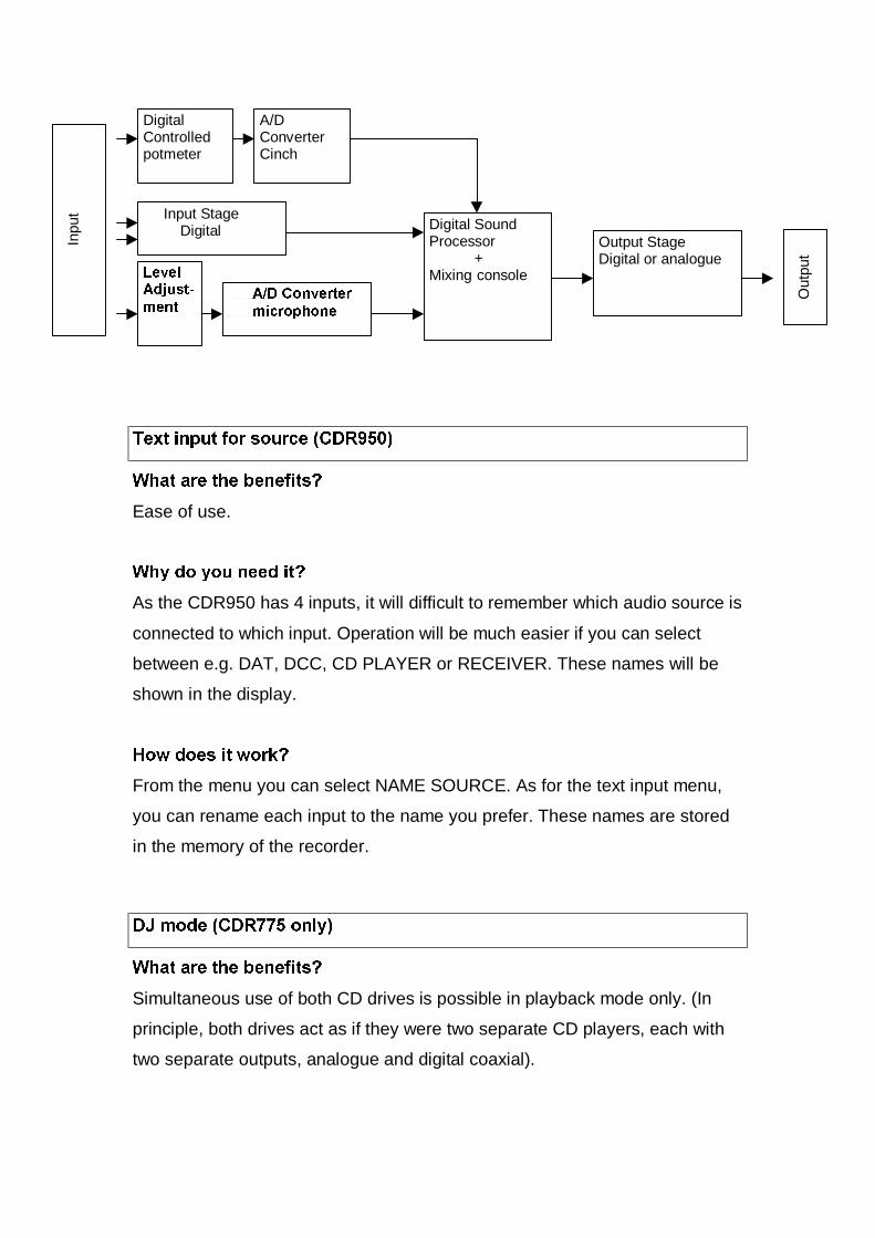
Input Stage Digital
$'&RQYHUWHUPLFURSKRQH
Digital SoundProcessor +Mixing console
Output StageDigital or analogue
/HYHO$GMXVWPHQW
DigitalControlledpotmeter
A/DConverterCinch
Inpu
t
Out
put
7H[WLQSXWIRUVRXUFH&'5
:KDWDUHWKHEHQHILWV"
Ease of use.
:K\GR\RXQHHGLW"
As the CDR950 has 4 inputs, it will difficult to remember which audio source is
connected to which input. Operation will be much easier if you can select
between e.g. DAT, DCC, CD PLAYER or RECEIVER. These names will be
shown in the display.
+RZGRHVLWZRUN"
From the menu you can select NAME SOURCE. As for the text input menu,
you can rename each input to the name you prefer. These names are stored
in the memory of the recorder.
'-PRGH&'5RQO\
:KDWDUHWKHEHQHILWV"
Simultaneous use of both CD drives is possible in playback mode only. (In
principle, both drives act as if they were two separate CD players, each with
two separate outputs, analogue and digital coaxial).

:K\GR\RXQHHGLW"
When using both drives together with a mixer, e.g. in a discotheque.
+RZGRHVLWZRUN"
A special button (DJ MODE) is provided on the recorder. It only works when
both drives are in playback mode. When this mode is activated, the recorder’s
microprocessor needs all the available capacity, which makes it impossible to
use the playback function simultaneously during recording.

5H:ULWDEOH&RPSDWLEOH3URGXFWV
The table below shows all Philips products per region which are currently
planned to be RW-compatible in 1999.
ReWritable-Compatible Products 1999:
Philips Regions
Product-group model-numbers Europe Eastern Europe USA AP ME&A Latam
Mini’s
FW350c, 390c,
398c
x/x/- x/x/- x/-/x -/-/x -/x/x -/x/-
FW545c, 548c,
555c, 585c,
590c, 595c
x/-/x/-/-/- x/x/-/-/x/- x/-/x/x/-/- -/-/-/-/-/x -/-/-/-/-/x -/x/-/-/-/-
FW768p, 798w x/x x/- x/x x/- x/- x/-
FW830c, 870c,
878c, 890p,
898w
x/x/-/x/- x/-/x/x/x x/-/-/x/- -/-/x/-/x -/-/x/-/- -/x/-/x/x
FW930r x - - - - -
MZ7 x x x - - -
Midi’s not compatible! not comp. not comp. not comp. not comp. not comp. not comp.
Micro’s
MC165 x x x x x x
MC175 x x x x x x
CD RCR
AZ1412 x - - - - -
AZ1518 x x x x x -
CD Portable
AZ7680 /81 /82
/88
x/x/x/- -/-/-/- -/x/-/- -/x/x/- -/x/x/- -/x/-/x
AZ7781 /82 /83
/84
x/x/x/x x/-/-/- x/-/x/- -/x/-/x -/x/-/x -/-/x/-
AZ7880 /81 /82
/83 /84
-/x/x/-/x -/-/x/-/- x/x/-/x/x -/-/-/-/x -/-/-/-/x -/-/-/-/-
AZ7495 x - - - - -
AZ7585 - - - x x -
AZ7794 x - - - - -
AZ7895 x - - x x -
CD Players
CD713 x - - - - -
CD723 x x - x - -
CD753 x x - x - -
CDC775 x x x x - -

Car CD *
DC-6 series x x x x x** x
DC-8 series x x x x x** x
*) All information on VDO Mannesmann is confidential and for internal use only!
**) Only Middle East, excluding Africa
:KLFKSURGXFWVZLOOKDYHGLJLWDORXWLQ
The table below shows all Philips products which are currently planned to
have digital out for recording.
0LQL¶V
FW396
FW545C
FW548C
FW555C
FW585C
FW590C
FW595C
FW768P (EXCEPT /37 USA
VERSION!)
FW798W
FW830C
FW840
FW870C
FW 878C
FW 890P
0LQL¶VFRQWLQXHG
FW 898W
FW 910R
FW 930R
FW 938
MZ7
&'SOD\HUV
CDC775
CD753
CD723
5HFHLYHUV
FR960
FR970
MX975D

&'5:'LJLWDO$XGLR'LVFV
'LIIHUHQFHEHWZHHQ&'5&'5:GLJLWDODXGLRGLVFVDQGVWDQGDUG
SUHUHFRUGHG&'V
The main physical difference between these two disc types and the standard
prerecorded CD (audio or CD-ROM) is that the latter has no recording layer:
the information is permanently stamped in the aluminium reflective layer.
There is also a difference in terms of the data areas on the disc. Compared
with standard CDs, the CD-R and CD-RW discs have an additional CD-R/CD-
RW area located in front of the lead-in area. This additional area is used to
store data specific to the recording process, and is divided into two parts:
• Program Memory Area (PMA), which contains the track numbers of the
recorded titles and their respective start and stop points.
• Program Calibration Area (PCA), which is used by the CDR to calibrate the
required laser energy by means of a trial recording (Optimum Power
Calibration)
7KH&'5GLVFYHUVXVWKH&'5:GLVF
Both CD-R and CD-RW discs have the same basic structure but with
significant detail differences. The CD-R disc has a dye-based recording layer,
with a reflectivity of 40-70%, while the CD-RW disc has a phase-change
recording layer with a lower reflectivity of 15-20%. Both discs have an
additional reflective layer: golden for the CD-R, which accounts for the
distinctive appearance, and silver (aluminium) for the CD-RW.
5HFRUGLQJRQD&'5'LJLWDO$XGLR'LVF
Digital information is written to the disc by burning (forming) pits in the
recording layer. The energy of the laser beam - in the range of 4 to 11 mW -
causes limited heating of the substrate and recording layer to approximately
250°C. At this, temperature the recording layer melts, reducing its volume,
while the substrate expands into the space that becomes available. By
constant switching between writing and reading power, a pit pattern
corresponding to that of a conventional CD is produced.

5HFRUGLQJRQD&'5:'LJLWDO$XGLR'LVF
In the CD-RW disc, the recording layer is made of an alloy of silver, indium,
antimony and tellurium. In its original state, this layer has a polycrystalline
structure. During the recording process, the laser selectively heats tiny areas
of the recording track to a temperature above the layer’s melting point (500 -
700°C) . For CD-RW writing, the laser power used is in the range of 8 to 14
mW.
The pulsed energy delivered by the laser beam melts the crystals in the
heated areas into a non-crystalline amorphous phase (‘pits’), which has a
much lower reflectance than the remaining crystalline areas (‘lands’). This
difference in reflectance allows the recorded data to be read-out, producing a
signal similar to that obtained from a standard CD. The physical
characteristics of the amorphous phase are ‘frozen-in’ during cooling, making
the recording just as permanent as any standard prerecorded CD.
(UDVLQJDQG2YHUZULWLQJD&'5:'LJLWDO$XGLR'LVF
Erasing of a CD-RW disc is performed by returning the material in the
recording layer, which was changed to the amorphous state during recording,
back to the crystalline state. This is done by heating the layer to a
temperature of about 200°C (less than the melting point) and maintaining that
temperature for an extended period (in practice 37 minutes for a complete
disc). The disc is then returned to its original - completely unrecorded - state.
A direct overwrite strategy is possible by combining the write and erase
techniques. In this case, new pits are written in the recording layer using the
same pulsed laser beam energy as in the standard writing strategy.

7KHQHZ+5&'5'LJLWDO$XGLR'LVFIURP3KLOLSV
In line with the fast-increasing market acceptance of our full range of Audio
CD Recorders, Philips has now introduced an enhanced CD-Recordable
Digital Audio disc, the +5which offers increased reliability and outdoor
playback performance.
HR 100 stands for +igh 5eliability for PRUHWKDQGD\VXQGHURXWGRRU
GLUHFWVXQOLJKWmaking the HR100 disc the ideal choice for portable and
outdoor playback applications.

6HUYLFHDSSURDFK
The 3rd generation CD recorders contain an adjusted CDRloader Module. For
this module a central repair is foreseen. This module contains the loader +
CDM and the mainboard. Electronic adjustments on mainboard have to be
carried out with special equipment. So to all repairs which concern the CDM
and/or de Servo part this adjustment has to be carried out. Mainboard can not
be interchanged with another CDM or loader!!! This means mainboard swaps
are not possible any longer.
For each modelnumber a new module has been defined:
CDR570/CDR930: 3104 129 52510 CDR570 MODULE SERVICE
CDR770: 3104 129 52520 CDR770 MODULE SERVICE
CDR775: 3104 129 52530 CDR775 MODULE SERVICE
CDR950: 3104 129 52540 CDR950 MODULE SERVICE
The rest of the set can be repaired on component level. Dedicated Service
manuals are available or still in preparation.
For Service manual CDR570/ CDR930 ordernumber reads
3104 125 40010.
For Service manual CDR770 ordernumber reads
3104 125 40020.
Service manuals for CDR775 and CDR950 are in preparation now.

For internal use only PHILIPS
ISSUE AS99.03 (99-07-12)Published by:Service Department Audio Systems
LINE OF BUSINESS AUDIO SYSTEMS
03.01 TYPENUMBER(S): FW350C, FW390C, FW398C, FW540C, FW545C, FW548C,FW555C, FW585C, FW590C, FW595C, FW748P, FW768P, FW798W,FW830C, FW840C, FW870C, FW878C, FW890P, FW898W
INFORMATION : Correction to the Service Manual, PartslistThe following flex-foils and flex-foil-connector were missing and havebeen added to the partlist of the 3CDC-99 Module (chapter 10).
pos. code number article description–––––––––––––––––––––––––––––––––––––––––––––1805 2422 025 09768 Flex-Foil-Connector 19P8001 4822 320 12232 Flex-Foil 15P 480mm8001 4822 320 12658 Flex-Foil 19P 480mm8001 4822 320 12659 Flex-Foil 23P 480mm8001 4822 320 12729 Flex-Foil 23P 400mm8005 3103 308 91820 Flex-Foil 15P 95mm
fig.1 – location of flex-foils
REMARKS :
SERVICE NEWSLETTER
Service Newsletter 1999 – Audio Systems 1/2

03.02 TYPENUMBER(S): FW540C, FW545C, FW548C, FW768P
INFORMATION : During production weeks 9921 to 9925, some sets have beenproduced without the Clip-Rectifier, that enhances the heat transferbetween Rectifier and Heatsink. Below pictures show the PowerSupply board with and without the Clip-Rectifier.
clip-rectifier missing clip-rectifier in position
REMARKS : All sets from production weeks 9921 to 9925 that come in for repairmust be checked – Missing clips have to be added as preventiveaction. The service code reads 4822 492 11068.
03.03 TYPENUMBER(S): FW570C/37
SYMPTOM :Fuse 1350 T315mA is blown.
CURE : The fuse blows because its application is near the marginal limit inworst case condition (most of the LEDs are on).The problem is resolved by changing:1) Fuse 1350 to T400mA type (2422 086 10612)2) Resistor 3480 to higher wattage PR02 type (2322 194 73109)
REMARKS : Production has already been stopped.Above solution is applicable for repair only.
C111IRIS CODE
Service Newsletter 1999 – Audio Systems 2/2

For internal use only PHILIPS
ISSUE PA99.02 (99-06-02)Published by:Service Department Portable Audio
LINE OF BUSINESS PORTABLE AUDIO
02.01 TYPENUMBER(S): ACT7580, ACT7581, ACT7582
INFORMATION : In order to improve the CD start-up behaviour, following parts havebeen changed:• Capacitor 2815 deleted• Capacitor 2823, 47pF (4822 122 33761) added• Resistor 3830 changed to 1kΩ (4822 051 30102)
REMARKS : Modification is implemented from production start onwards.
02.02 TYPENUMBER(S): AJ3080
SYMPTOM :The fuse is blown out.
CURE : The fuse will blow if the CLOCK switch is set to ALARM and theSLUMBER button is pressed.The problem can be soved by replacing jumper 9022 by a 1kΩresistor (4822 050 11002).
REMARKS : Modification has been implemented in production from week 9910onwards.
02.03 TYPENUMBER(S): AJ3935
INFORMATION : In course of production, following parts are changed to improvedistortion at maximum volume.• Resistors 3201 and 3204 changed to 820Ω (4822 117 11454)• Resistors 3221 and 3222 changed to 3.3kΩ (4822 051 20332)
REMARKS : Modification is implemented from production start onwards.
X11CIRIS CODE
SERVICE NEWSLETTER
Service Newsletter 1999 – Portable Audio 1/4
02.04 TYPENUMBER(S): AJ3940
SYMPTOM :The transformer hum is audible.
CURE : Hum is caused by the vibration of shielding plate which is mountedon top of mains transformer. The shield plate is a construction of 3metal layers which are sticked together by means of double-sidedadhesive tape. If the layers are not pressed together properly, theshield plate will vibrate.To solve the problem, we suggest to dismantle the shield plate andhammer it against a solid surface.
REMARKS : From production week 9905 onwards, a press jig has been used toensure shield plates are well pressed.
02.05 TYPENUMBER(S): AZ1009, AZ1010
INFORMATION : CD-drive CD94V5T1 has been replaced by the new type DA114822 691 10747.To adapt the electronic circuitry to the new CD-drive followingcomponents have been changed on the Combi Board:3828 changed from 18kΩ to 68kΩ (4822 116 52297)3851 changed from 10kΩ to 15kΩ (4822 116 52244)3853 changed from 15kΩ to 18kΩ (4822 116 52251)3855 changed from 33kΩ to 27kΩ (4822 116 52264)
REMARKS : Modification has been implemented in production from week 9912onwards. Sets with the new CD-drive are marked with factory changecode KT03.This info will be followed by Service Information A99-350(4822 725 26032).
02.06 TYPENUMBER(S): AZ1120
INFORMATION : In order to improve the ESD behaviour, coil 5100 has been changedto 2.2mH (3198 018 12280).
REMARKS : Modification is implemented from production start onwards.
02.07 TYPENUMBER(S): AZ1202
INFORMATION : In course of production, following parts have been changed to re-adjust the amplification reserve of CD signal.• Resistors 3302 and 3303 changed to 270Ω (3198 011 02710)• Resistors 3595 and 3596 changed to 22kΩ (3198 011 02230)• Resistors 3597 and 3598 changed to 15kΩ (3198 011 01530)
REMARKS : Modification has been implemented in production from week 9915onwards.
4411IRIS CODE
Service Newsletter 1999 – Portable Audio 2/4

02.08 TYPENUMBER(S): AZ1202, AZ1207, AZ1209
INFORMATION : The Cassette Door Spring (pos. 407) looses out easily.To solve the problem, the shape of the spring has been changed.The code number of the new spring is 3140 111 00620.
REMARKS : Modification has been implemented in production from week 9915onwards.
02.09 TYPENUMBER(S): AZ2000
INFORMATION : In course of production, following parts on the Combi Board havebeen changed to improve sound quality:• Capacitors 2518 and 2519 changed to 10nF (4822 121 51387)• Jumpers 9555 & 9556 replaced by resistors 3590 and 3591, 2.2kΩ
(4822 116 52256)• Resistors 3559 and 3560, 10kΩ (4822 050 21003) added across
pins 1 to 6 and 3 to 5 of volume control 3522• Resistors 3595 and 3596 changed to 56kΩ (4822 116 52291)
REMARKS : Modification has been implemented in production from week 9910onwards.
02.10 TYPENUMBER(S): AZ2000
SYMPTOM :CD does not operated because IC 7801 (M65821) is defective.
CURE : IC7801 is damaged by overheating because its location is too closeto the heatsink of the Power IC.The problem can be solved by reducing the supply voltage of the CDmodule:• Replace jumper 9526 by a resistor 3315, 4.7Ω (4822 050 4708) on
Combi Board
REMARKS : Modification has been implemented in production from week 9913onwards.
02.11 TYPENUMBER(S): AZ2000
INFORMATION : In order to improve reliability, transistor 7260 has been changed fromBC327-40 to BC369 (5322 130 44593).Due to different transistor-pinning, the layout of the printed board hadto be modified.Layout stage “3140 113 3139.2” uses BC327-40Layout stage “3140 113 3139.3” uses BC369
REMARKS : Modification has been implemented in production from week 9921onwards.
1154IRIS CODE
Service Newsletter 1999 – Portable Audio 3/4
02.12 TYPENUMBER(S): AZ2402
SYMPTOM :The Power ON/OFF switch 1496 is burst.
CURE : The transient current through the switch is too high.To reduce the transient current we suggest the following changes:• Replace 3594 by a 10Ω fusible resistor (4822 052 11109)• Change 2567 to 100µF/25V (4822 124 40207)
REMARKS : Modification has been implemented in production from week 9913onwards.
X116IRIS CODE
Service Newsletter 1999 – Portable Audio 4/4
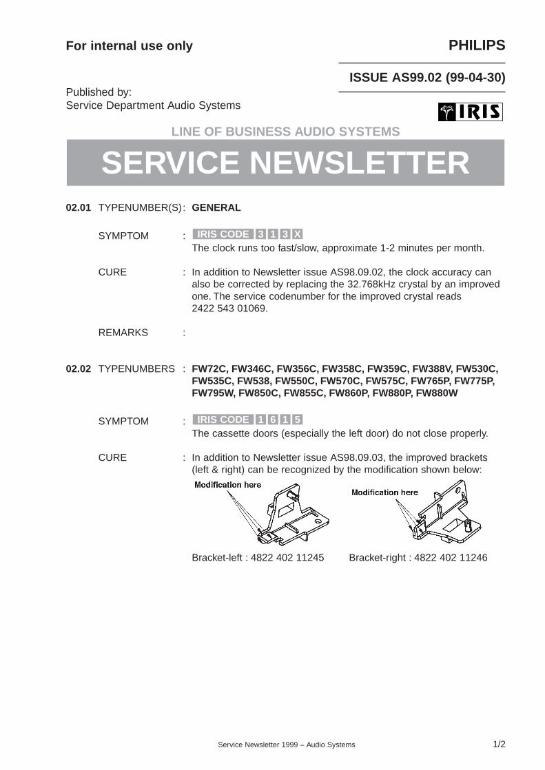
For internal use only PHILIPS
ISSUE AS99.02 (99-04-30)Published by:Service Department Audio Systems
LINE OF BUSINESS AUDIO SYSTEMS
02.01 TYPENUMBER(S): GENERAL
SYMPTOM :The clock runs too fast/slow, approximate 1-2 minutes per month.
CURE : In addition to Newsletter issue AS98.09.02, the clock accuracy canalso be corrected by replacing the 32.768kHz crystal by an improvedone. The service codenumber for the improved crystal reads2422 543 01069.
REMARKS :
02.02 TYPENUMBERS : FW72C, FW346C, FW356C, FW358C, FW359C, FW388V, FW530C,FW535C, FW538, FW550C, FW570C, FW575C, FW765P, FW775P,FW795W, FW850C, FW855C, FW860P, FW880P, FW880W
SYMPTOM :The cassette doors (especially the left door) do not close properly.
CURE : In addition to Newsletter issue AS98.09.03, the improved brackets(left & right) can be recognized by the modification shown below:
Bracket-left : 4822 402 11245 Bracket-right : 4822 402 11246
5161IRIS CODE
X313IRIS CODE
SERVICE NEWSLETTER
Service Newsletter 1999 – Audio Systems 1/2

Sets with old brackets can be adapted by either
i) adding a metal bracket (4822 402 11331) to press onto theback of the bracket left or right as shown below, or
ii) replacing the old bracket by the modified one.
REMARKS :
02.03 TYPENUMBER(S): FW388V
SYMPTOM :Tuner preset stations cannot be selected via the numeric key-pad(0..9) of the remote control.
CURE : This feature is not available on the set.It is an error in the IFU which is corrected with an addendum sheetfrom wk904 onwards.
REMARKS :
02.04 TYPENUMBER(S): FW850C, FW855C, FW860P, FW880P, FW880W
SYMPTOM :Mic-mixing cannot be recorded when the selected source is TAPE 1.
CURE : Recording of mic-mixing with TAPE 1 source is not supportedbecause the set will switch automatically into dubbing mode.The IFU (section “Recording the mixed sound”) causes someconfusion but will not be updated as production will end in April 1999.
REMARKS :
165CIRIS CODE
1511IRIS CODE
Service Newsletter 1999 – Audio Systems 2/2

For internal use only PHILIPS
ISSUE PA99.01 (99-03-18)Published by:Service Department Portable Audio
LINE OF BUSINESS PORTABLE AUDIO
01.01 TYPENUMBER(S): AQ6581
SYMPTOM :Tape sound is distorted near strong electro-magnetic fields.
CURE : Problem can be solved by connecting two 390pF ceramic capacitors(4822 122 32121) from pins 6 and 23 to pin 10 (ground) of ICLAG668.
REMARKS :
01.02 TYPENUMBER(S): AZ1015
INFORMATION : Correction to the Electrical Partslist:The service codenumbers of the Mains transformers have beenmixed up. They should read:4822 146 10877 for /00 and /14 versions4822 146 11118 for /01 version4822 146 10876 for /17 version
REMARKS :
01.03 TYPENUMBER(S): AZ1025
INFORMATION : In order to increase the tuner output power, following parts have beenchanged on the Audio Board:• Resistors 3307 and 3308 changed to 150Ω (4822 116 83868)• Resistors 3595 and 3596 changed to 27kΩ (4822 116 52264)• Resistors 3597 and 3598 replaced by jumpers
REMARKS : Modification has been implemented from production start onwards.
2352IRIS CODE
SERVICE NEWSLETTER
Service Newsletter 1999 – Portable Audio 1/3
01.04 TYPENUMBER(S): AZ1200, AZ1202, AZ1203, AZ1205, AZ1207, AZ1208, AZ1209
SYMPTOM :No display in CD mode at low battery voltage.
CURE : Problem can be solved by changing resistor 3251 from 470Ω to 390Ω(4822 116 83881).
REMARKS : Modification has been implemented in production from week 9850onwards.
01.05 TYPENUMBER(S): AZ1202
INFORMATION : Correction to the Mechanical Partslist:The service codenumber of the Knob-Open (item 439) for Silverversions should read 4822 410 11392.
REMARKS :
01.06 TYPENUMBER(S): AZ1205, AZ1207
SYMPTOM :Volume setting is reset to level “11” when power is switched off.
CURE : Problem can be solved by changing capacitor 2401 from 100µF to47µF (4822 124 81286).
REMARKS : Modification has been implemented in production from week 9901onwards.
01.07 TYPENUMBER(S): AZ8310, ND7600
INFORMATION : In course of production the potentiometers VR1, VR4, VR5 and VR6have been changed. The new potentiometers are available viafollowing service codenumbers:VR1 : 4822 101 11373VR4 to VR6 : 4822 105 11133
REMARKS : The potentiometers can be distinguished by their pin layout:Old potentiometers : 4 pins in 1 rowNew potentiometers : 4 pins in 2 rows
5252IRIS CODE
X31CIRIS CODE
Service Newsletter 1999 – Portable Audio 2/3

01.08 TYPENUMBER(S): MC135, MC136, MC155, MC156
SYMPTOM :Sound is muted or distorted at start-up when playing a CD containingonly two tracks.
CURE : The problem can be solved by adding a resistor of 100kΩ(4822 116 52234) across C445 on the CD board.
REMARKS : Modification has been implemented in production from week 9901onwards.
01.09 TYPENUMBER(S): MC175
INFORMATION : Correction to the Service Manual, Frontboard:Following parts have been added/changed from production startonwards:• Capacitor 2430 changed from 100pF to 470nF (4822 126 13482)• Jumper 9440 replaced by resistor 3525, 47Ω (4822 116 52195)• Resistor 3526, 680kΩ (4822 051 20684) added• Resistor 3527, 1MΩ (4822 051 20105) added
REMARKS :
235CIRIS CODE
Service Newsletter 1999 – Portable Audio 3/3

For internal use only PHILIPS
ISSUE AS99.01 (99-02-12)Published by:Service Department Audio Systems
LINE OF BUSINESS AUDIO SYSTEMS
01.01 TYPENUMBER(S): CDC751, CDC752
INFORMATION : During transportation the pin on the Crank (pos 96) might jump out ofthe groove on the Tray (pos 108).
From production wk9835 onwards, the Tray and Crank have beenmodified. The groove on the tray is now deeper and likewise the pinon the Crank is 3mm longer.
Due to this change the new Crank does not fit into the old Trayanymore. But it is still possible to use the old Crank on the new Tray.
The service code numbers for the Cranks are as follows:4822 535 40105 Old Crank4822 402 11241 New Crank
SERVICE NEWSLETTER
Service Newsletter 1999 – Audio Systems 1/10

The new Tray can be recognized by its 10mm deep groove.
Because of limited stock of old Cranks, new Cranks have to bereworked for sets with an old Tray. This is done by cutting the pin by3mm with a sharp NT-cutter (give it a clean cut & do not deform itscircular cross-section) as shown below.
REMARKS :
01.02 TYPENUMBER(S): CDC775
INFORMATION : Corrections to the Service ManualOn page 1-2, CDC775/01 a 2-position voltage selector is showninstead of a 4-position type.The 4 positions are: 110V/127V/220-230V/240V.
On page 8-4, capacitor 2863 and resistor 3885 are drawn asprovision. Both components will be assembled from production startonwards to improve playability of “Thin Disc”.2863 4822 126 13689 18pF 1% 63V3885 4822 051 20153 15kΩ 5% 0,1W
REMARKS :
Service Newsletter 1999 – Audio Systems 2/10

01.03 TYPENUMBER(S): ALL CDR TYPENUMBERS
INFORMATION : The user problems in this publication are separated into the followingcategories:1. Playback behaviour2. Recording behaviour3. Operating behaviour
1. PLAYBACK
1.1. Display indicates: No disc Indeed no disc inserted Inserted disc is not recognised by Loader CDR mechanism
(defective disc or damaged disc) Does the set work properly with another CDDA disc (pre-recorded Audio disc)? If Yes then disc is indeed defective If No then check the functioning of the set. Disc is not positioned correctly on tray at inserting and therefore not recognised by
Loader CDR mechanism, reposition disc on tray.
1.2. CD-RW disc is not recognised Is it a CD-RW Digital Audio disc? If Yes and if the set is working properly on other recording discs, this particular disc
should be “DC-Erased” (Power off, ERASE + RECORD simultaneously and switchPower on) This operation takes about 37 minutes and returns that CD-RW disc to itsvirginal status again.
2. RECORDING
2.1. Analogue input signal recorded is distorted at Playback. When recording analogue signals via tape or cassetterecording customer is used to
overpower the input signal. This brings more dynamic in recorded signal. For digital recording there is enough dynamic space between 0 dB till about -95 dB, so
overpowering is not necessary, the opposite is true; by digitalizing an overpoweredsignal ‘mutes’ are converted, resulting in the distorted stored signal
2.2. Digital connected, tracks are not incremented Is Auto track increment function switched on. If not switch on Automatic track increment Digital source is using another digital output than IEC958 format (consumer part). This
is due to the transmitted subcode information which contains other data than the sub-code information in the CD-format. To have the advantage of digital recording, theDigital Audio Data is recorded without any problem. However the track-increment bit isnot transferred.
Service Newsletter 1999 – Audio Systems 3/10

2.3. Disc full after some or a few tracks.Disc full message can be the result after a misrecording. Misrecordings due to customer actions are:
• bumps against recorder: prevent bumps onto the set during recording process.• dust on disc: prevent dust particles on disc• scratches on disc: prevent scratches on disc• set is suddenly powered off: prevent switching off!!
Misrecording due to improper working of CD Recording Module:• In case the error occurs always at the same time indication then Optical Pick-up Unit
is not exactly following the Pregroove track on that position: replace CD-RecordingModule (CDR765, CDR760, CDR560, CDR538; 4822 691 10737) or the CDRLoadermodule part CDR870, CDR880: 4822 218 12745)
In case a CD-R disc is used, each misrecording will automatically activate the finalizingprocess of the recorder, because after a misrecording it is not possible to add furtherrecordings onto that CD-R disc. To have all proper recordings stored, the TOC of thedisc is filled.
In case a CD-RW disc is used, the last recorded track will be overwritten when makingfurther new recordings. Here the disc is not finalized automatically, but PMA (programmemory area) is filled with the number of proper recorded tracks.
2.4. Analog input is so low that tracknumber is incremented and recording stops. If analog input signal starts very low (-35 dB) and automatic track increment is switched
on then track nummer x will be followed by next number (x+1) after 4 seconds. If thislow signal still continues the recording will be switched off after some seconds.
By applying Manually track increment this signal can be recorded. Automatic switch off has been modified by adapting µP software program in CDR765,
CDR760, CDR560, CDR538.
2.5. Loud noise on CD-RW disc CD-RW erasings are only done in PMA. The original signal will be overwritten later on. It
might occur that the overwriting does not start at exactly the beginning of the frame ofthe track to be overwritten. In case overwritten signal consisted out of loud signal, thenthis short remaining signal can give this suddenly loud noise.
For this phenomenon no better solution is possible.
3. OPERATING
3.1. Finalizing takes approx. 5 minutes Normally finalizing takes approx. 2 minutes. Due to the fact that finalizing is done at speed N=2. In case something goes wrong finalizing is automatically switched over to speed N=1
and procedure will restart. (4 minutes) Now in IFU is stated: “ Finalizing takes at least 2 minutes”
3.2. CD-sync activated and in first track 1 second deviation upon original disc. Via CD-sync, the recorder is brought in record standby position at the last recorded
position on the program area. When CD-player is started the digital signal is brought to digital in. When this signal
arrives immediately the linking procedure starts. After reading the last recorded 14frames the recording of the digital input signal starts. As no buffer is used the firstframes are not stored. (Max. about 400 msec. are lost)
Service Newsletter 1999 – Audio Systems 4/10

3.3. How to erase one track between other tracks on CD-RW disc? It is not possible to erase tracks between other tracks. Only the last recorded track can
be erased. In case of an erasure between tracks make first a copy of the to be safedtracks to another disc and then erase track after track to the desired position and addstored recording again.
3.4. Can a copy of another copy be made? For Philips Digital Audio CDR recorders SCMS protocol is valid This applies even to devices without a digital output SCMS allows any number of digital copies of original sound carriers, but prevents
further digital copies of this created master. copies of this created master can only be made via D/A -> A/D conversion. According to audio interface standard IEC958, via channel status bit (timeslot30), the
channel status word consists out of 384 bits per blok,each bit repeated twice so 192channel status bits per blok are available. In channel status word every digital source isidentified by an 8-bit “category code” Category code is formed by bit 8-15 of the channelstatus word.
bit 15 of timeslot 30 or the last bit of the category code is called L-bit. This bitindicates an original source, commercially released pre-recorded software (L=“1”) or apersonal recording or “home copy” (L=“0”) No indication.
Control code gives the transmission mode and the copy protection status of the signalthat is transmitted.
the transmission mode is given by the bits 0 and 1 of the channel status word. Bit 2 contains the copy status (C-bit). C-bit = “0” for protected and “1” for unprotected material ”alt” for “home copy of copyright
protected original” On recorded disc the copy bit defines the copy status: Q-control bit 1 (copy bit) copy protection status: Q-control bit 1 = “1” for protected, Q-control bit 1 = “0” for unprotected material Q-control bit 1 = alternating between “0” and “1” (alt) for “home copy of copyright
protected original”
On recorded disc the copy bit defines the copy status summarised in one table:
3.5. Can CD-i disc be copied to Audio CDRrecorder? Digitally connected only the CD DA tracks on that disc CD-i disc complete is not possible, only CD DA discs. Only via analogue connection the Audio signal can be copied
3.6. Can VCD disc be copied to Audio CDRrecorder? Digitally connected only the CD DA tracks on that disc VCD disc complete is not possible, only CD DA discs Only via analogue connection the Audio signal can be copied
kcabyalP:csid
gnimocsgalFmorf
1tiblortnoc-Q
tuptuolatigidtasutatslennahC mumixaMelbissop
seipoc2tib=”tib-C“yrogetaC
edoc51tib=”tib-L“
,R-DC,DCWR-DC
10tla
10tla
000000010000000100000001
000
etinifnI10
Service Newsletter 1999 – Audio Systems 5/10

3.7. Can CD-ROM disc be copied to Audio CDRrecorder? Digitally connected only the CD DA tracks on that disc. CD-ROM disc complete is not possible, only CD DA discs Only via analogue connection the Audio signal can be copied
3.8. Can more than one digital connection be made from one source? Only one digital connection per output can be made. Using more digital recorders which
are digitally connected via Input and Output sockets behind each other is very limitedbecause the IEC958 clockbit will deviate too much, resulting in a non proper recording.
3.9. Display indicates: No Audio Professional Recording Disc has been inserted in loader use Digital Audio CD-R or Digital Audio CD-RW discs.
01.04 TYPENUMBER(S): CDR538, CDR560, CDR760
INFORMATION : To solve “No copy“ problem in FW538 systems when recordingdigitally new software version V2.4. has been introduced.
With SW V2.4 the unit will go into Record Standby after recordinginstead of Stop. If no further audio signals are presented for recordingwithin 1 minute after going into Standby mode, the unit will go toStop. This solves the problem of recording with CD Changer systems.
The new SW V2.4 has to be implemented for IC 7322 on the CDRMain Board and is available under service codenumber4822 900 11306.
REMARKS : SW V2.4 has been introduced in production:for CDR538/00S, CDR560/00S and CDR560/06S in week 9849marked with AH-no. 03.for CDR560/11S in week 9902 with AH-no. 02.for CDR560/17 in week 9902 with AH-no. 01.
01.05 TYPENUMBER(S): CDR538, CDR560, CDR760, CDR765
INFORMATION : Whenever the CDR Loader Module is removed for replacement, theflex foil cables connecting the CDM-board and the CDR Main Boardshould be included in the shipment because they are part of theLoader Module.
REMARKS :
01.06 TYPENUMBER(S): CDR538, CDR560, CDR760, CDR765
INFORMATION : In the central repair which is organized for the CDR-loader module ofabove mentioned sets, the new part (4822 691 10737) isaccompanied by a fill in form. Please take care for actual inserting ofall available information which will help to make a diagnosis about thereturned defective loader, in case this form is not filled in therestitution will not be activated. Find on one of the next pages the fill-in form for repair 4822 691 10737.
REMARKS :
Service Newsletter 1999 – Audio Systems 6/10

01.07 TYPENUMBER(S): CDR538, CDR560, CDR760, CDR765, CDR870, CDR880
INFORMATION : A new Tray Locking Device has been released to increase the safetyof the units during transportation. It is strongly recommended to usethis new device whenever the unit needs to be transported. The newlocking device can be ordered using the service codenumber4822 466 12204.
REMARKS :
01.08 TYPENUMBER(S): CDR765
SYMPTOM :Shock sensitivity CD-Player part, audio-mutes on recorded CD afterdubbing
CURE : The CD-Player module is very sensitive to shocks. Also duringdubbing of an audio-CD, mutes can be heard on the recorded CD.These mutes are mostly located in track 1. Both of these problemscan be solved by a software upgrade to V1.6 for IC 7220 on the CDMain Board. Service code number reads 4822 900 11309.
The shock sensitivity problem had already been addressed in item08.06 of issue AS98.08 (98-10-30) of the Service Newsletter. Thecure for the above problem(s), as mentioned in that ServiceNewsletter, needs to be changed as follows:
Upgrading IC 7220 on the CD Main Board to SW V1.6, solves theproblems of shock sensitivity and audio mutes, regardless of thesuspension grommets used in the CD-Player module.
REMARKS : Together with the new software V1.6, the original black suspensiongrommets will be reintroduced into production from week 9903onwards.The CD-Loader unit with modified software has been marked VN03.The set with built-in modified software has been marked VN04.
01.09 TYPENUMBER(S): CDR870
INFORMATION : A printing error has occurred on the front page of the CDR870Service Information Issue A98-250. The service codenumber of part1520 should read 4822 218 11487 instead of 4822 218 11987.
REMARKS :
3557IRIS CODE
Service Newsletter 1999 – Audio Systems 7/10

01.10 TYPENUMBER(S): CDR870
INFORMATION : In the central repair which is organized for the CDR-loader module ofabove mentioned sets, the new part (4822 691 10644) isaccompanied by a fill in form. Please take care for actual inserting ofall available information which will help to make a diagnosis about thereturned defective loader, in case this form is not filled in therestitution will not be activated. Find on one of the next pages the fill-in form for repair 4822 691 10644.
REMARKS : Instead of 4822 691 10644 can be delivered 4822 214 12745(CDR880 version of the module). This loader module is backwardscompatible for CDR870.
01.11 TYPENUMBER(S): CDR880
INFORMATION : In the central repair which is organized for the CDR-loader module ofabove mentioned sets, the new part (4822 214 12745) isaccompanied by a fill in form. Please take care for actual inserting ofall available information which will help to make a diagnosis about thereturned defective loader, in case this form is not filled in therestitution will not be activated. Find on one of the next pages the fill-in form for repair 4822 214 12745.
REMARKS :
01.12 TYPENUMBER(S): CDR880
INFORMATION : Upgrading of software V1.4 to V1.7 for EPROM 7322 (servicecodenumber 4822 900 11271) will make it possible to erase the TableOf Contents (TOC) when unfinalizing a CD-RW disc.
This software upgrade will also automatically stop a recording sessionafter the source has stopped or after disconnection of the source(Autostop).
REMARKS : SW V1.7 will be introduced from week 9904 onwards with AH-no. 02for CDR880/00, CDR880/00S, CDR880/06S and CDR880/17.
Service Newsletter 1999 – Audio Systems 8/10

01.13 TYPENUMBER(S): FW14, FW15, FW36, FW56, FW351C/37, FW360C, FW620C,FW650C, FW670P, FW680VAZ3705, AZ3708 (PORTABLE AUDIO)FW350C, M6, M25, M26 (GRUNDIG)74MX540 (MARANTZ)
INFORMATION : Replacement of CDM12.1 for 7-Disc ChangerProduction of CDM12.1 will stop. For service purpose CDM12.1(4822 691 30278) will be replaced by service kit VAM1201(4822 310 11263) when stock depletes.
For the above mentioned sets with 7-Disc Changer the newVAM1201 does not fit.
As an alternative, the CDM12.1 can be replaced by CDM12.1/T(4822 691 30343) without any further modifications.
REMARKS :
01.14 TYPENUMBER(S): FW45C, FW52C, FW55C, FW62C, FW65C, FW72C, FW316C,FW318C, FW320C, FW338C, FW339C, FW346C, FW356C,FW358C, FW359C, FW380C, FW386C, FW510C, FW520C,FW530C, FW535C, FW538, FW550C, FW560C, FW570C, FW575C,FW754P, FW755P, FW765P, FW775P, FW795W, FW850C, FW855C,FW860P, FW880P, FW880W
SYMPTOM :When CD tray was activated to open, the tray would move out andimmediately go in again or stop at half way.When the CD tray is in motion the inside arm of the switch bracket(pos 123) hits the micro switch earlier than the main lever.
CURE : The problem can be solved by cutting a section of the inside arm ofthe switch bracket as indicated below:
REMARKS : The phenomenon can be simulated by tilting the set at either side for1cm or more.
X761IRIS CODE
Service Newsletter 1999 – Audio Systems 9/10

01.15 TYPENUMBER(S): FW335, FW355C, FW365C, FW375P, FW710C, FW725C, FW730C,FW745C, FW750C, FW770P, FW780P, FW790P
SYMPTOM :Hum & crackling sound problem
CURE : The problem is caused by defective capacitors at positions 2617 and2618 on the AF3-board.It is resolved by replacing them with new ones.
REMARKS :
01.16 TYPENUMBER(S): FW362, FW363, FW372C, FW373C, FW395C
INFORMATION : Correction to the Service Test ProgramTo enter the Service Test Program hold buttons B1 & C4 depressedwhile powering-up the set.B1 = Program (interactive display - top right vertical button)C4 = Tuning Up (interactive display - far right horizontal button)
REMARKS :
1451IRIS CODE
Service Newsletter 1999 – Audio Systems 10/10

GUIDANCE FORMREPAIRABLE UNIT 4822 691 10737
______________________________________________________________________________________________________
Please fill in this form and return it with the defective unit.
Typenumber (unit demounted from set) : CDR760/..................or : CDR..........................
Serial number : ...................................................Unit serial number (CDR Module) : CDL3610/01;....VO........................
______________________________________________________________________________________________________
Warning: Only Returned Loader with filled in Guidance form are accepted.
In case CDR-disc has been damaged, please include this damaged disc with theexchanged CDR Module.
DISC DAMAGED? Y/NDISC INCLUDED? Y/N
INFORMATION GATHERED VIA SERVICE TEST MODESwitch POWER ON,Activate OPEN/CLOSE,Insert test disc SBC444A, or any other CD-Digital Audio disc;switch POWER OFF,<PLAY>+<NEXT>+<POWER ON> keep all keys pressed for 2 secondsDuring test:Blinking ‘D’ on display (about 2 minutes!!);Blinking ‘B’ on display (for some seconds).
ERROR INDICATION (on display) according to table below: Y/NON DISPLAY IRIS
SYMPTOMCODE
YES *)
DISPLAY TEST RESULTRAM error DERR 1 15.... **)ROM error DERR 2 16.... **)
EEPROM error DERR 3 16.... **)DAIO error DERR 4 15.... **)
BASIC ENGINE TESTRESULT
Communication bus error BERR 1 15....Basic Engine error BERR 2 15....
Disc test error BERR 3 16....*) insert cross at seen display result**) replace concerned mainboard

IN CASE OF NO ERROR INDICATION;OTHER PROBLEMS OCCURED AT:
PLAYBACK CD CDRUnfinalised
CDRFinalised
CDRWUnfinalised
CDRWFinalised
Y/NRECORDING CD CDR
UnfinalisedCDR
FinalisedCDRW
UnfinalisedCDRW
FinalisedY/N -----
IRIS CONDITION CODE:DESCRIPTION CONDITION CODE
Constantly 1...Intermittently 2...After a while 3...
In a hot environment 4...In a cold environment 5...
IRIS SYMPTOM CODE CONCERNING AUDIOAudio Audio Audio Audio Audio
No sound Level Quality Noisy Poorrecording
.51. .52. .53. .54. .56.
______________________________________________________________________________________________________
OTHER COMPLAINT DESCRIPTION :( IRIS SYMPTOM CODE: ....................... )
______________________________________________________________________________________________________
Return the defective module complete assembled in original package to:Invoice to:Philips Consumer Electronics B.V. 670005Philips Consumer Service - F&A ReportingGlaslaan 2, Building SBP55616 LW EindhovenThe Netherlands
Ship to:Philips Consumer Electronics B.V. 676723LO PCS WAREHOUSINGGlaslaan 2, Building SBI p5616 LW EindhovenThe NetherlandsATT: Mr. C. Lieberwirth
______________________________________________________________________________________________________
CORRECTIVE ACTION/SOLUTION (to be filled in at central repair workshop): Report number:..............
Iris repair code:......................

GUIDANCE FORMREPAIRABLE UNIT 4822 691 10644
______________________________________________________________________________________________________
Please fill in this form and return it with the defective unit.
Typenumber (unit demounted from set) : CDR870/..................or : CDR..........................
Serial number : ...................................................Unit serial number (CDR Module) : CDL3610/01; ....VO........................
______________________________________________________________________________________________________
Warning: Dismantling of the CDR Module is not allowed. Guarantee will be invalidated.Only Returned Modules with filled in Guidance form are accepted.
In case CDR-disc has been damaged, please include this damaged disc with theexchanged CDR Module.
DISC DAMAGED? Y/NDISC INCLUDED? Y/N
INFORMATION GATHERED VIA SERVICE TEST MODESwitch POWER ON,Activate OPEN/CLOSE,Insert test disc SBC444A, or any other CD-Digital Audio disc;switch POWER OFF,<PLAY>+<NEXT>+<POWER ON> keep all keys pressed for 2 secondsDuring test:Blinking ‘D’ on display (about 2 minutes!!);Blinking ‘B’ on display (for some seconds).
ERROR INDICATION (on display) according to table below: Y/NON DISPLAY IRIS
SYMPTOM CODEYES *)
DISPLAY TEST RESULTRAM error DERR 1 15....ROM error DERR 2 16....
EEPROM error DERR 3 16....DAIO error DERR 4 15....GDIN error DERR 5 15....
BASIC ENGINE TEST RESULTCommunication bus error BERR 1 15....
Basic Engine error BERR 2 15....Disc test error BERR 3 16....
*) insert cross at seen display result

IN CASE OF NO ERROR INDICATION;OTHER PROBLEMS OCCURED AT:
PLAYBACK CD CDRUnfinalised
CDRFinalised
CDRWUnfinalised
CDRWFinalised
Y/NRECORDING CD CDR
UnfinalisedCDR
FinalisedCDRW
UnfinalisedCDRW
FinalisedY/N -----
IRIS CONDITION CODE:DESCRIPTION CONDITION CODE
Constantly 1...Intermittently 2...After a while 3...
In a hot environment 4...In a cold environment 5...
IRIS SYMPTOM CODE CONCERNING AUDIOAudio Audio Audio Audio Audio
No sound Level Quality Noisy Poorrecording
.51. .52. .53. .54. .56.
______________________________________________________________________________________________________
OTHER COMPLAINT DESCRIPTION :( IRIS SYMPTOM CODE: ....................... )
______________________________________________________________________________________________________
Return the defective module complete assembled in original package to:Invoice to:Philips Consumer Electronics B.V. 670005Philips Consumer Service - F&A ReportingGlaslaan 2, Building SBP55616 LW EindhovenThe Netherlands
Ship to:Philips Consumer Electronics B.V. 676723LO PCS WAREHOUSINGGlaslaan 2, Building SBI p5616 LW EindhovenThe NetherlandsATT: Mr. C. Lieberwirth
______________________________________________________________________________________________________
CORRECTIVE ACTION/SOLUTION (to be filled in at central repair workshop): Report number:..............
Iris repair code:......................

GUIDANCE FORMREPAIRABLE UNIT 4822 214 12745
______________________________________________________________________________________________________
Please fill in this form and return it with the defective unit.
Typenumber (unit demounted from set) : CDR880/..................or : CDR..........................
Serial number : ...................................................Unit serial number (CDR Module) : CDL3610/01; ....VO........................
______________________________________________________________________________________________________
Warning: Dismantling of the CDR Module is not allowed. Guarantee will be invalidated.Only Returned Modules with filled in Guidance form are accepted.
In case CDR-disc has been damaged, please include this damaged disc with theexchanged CDR Module.
DISC DAMAGED? Y/NDISC INCLUDED? Y/N
INFORMATION GATHERED VIA SERVICE TEST MODESwitch POWER ON,Activate OPEN/CLOSE,Insert test disc SBC444A, or any other CD-Digital Audio disc;switch POWER OFF,<PLAY>+<NEXT>+<POWER ON> keep all keys pressed for 2 secondsDuring test:Blinking ‘D’ on display (about 2 minutes!!);Blinking ‘B’ on display (for some seconds).
ERROR INDICATION (on display) according to table below: Y/NON DISPLAY IRIS
SYMPTOM CODEYES *)
DISPLAY TEST RESULTRAM error DERR 1 15....ROM error DERR 2 16....
EEPROM error DERR 3 16....DAIO error DERR 4 15....GDIN error DERR 5 15....
BASIC ENGINE TEST RESULTCommunication bus error BERR 1 15....
Basic Engine error BERR 2 15....Disc test error BERR 3 16....
*) insert cross at seen display result

IN CASE OF NO ERROR INDICATION;OTHER PROBLEMS OCCURED AT:
PLAYBACK CD CDRUnfinalised
CDRFinalised
CDRWUnfinalised
CDRWFinalised
Y/NRECORDING CD CDR
UnfinalisedCDR
FinalisedCDRW
UnfinalisedCDRW
FinalisedY/N -----
IRIS CONDITION CODE:DESCRIPTION CONDITION CODE
Constantly 1...Intermittently 2...After a while 3...
In a hot environment 4...In a cold environment 5...
IRIS SYMPTOM CODE CONCERNING AUDIOAudio Audio Audio Audio Audio
No sound Level Quality Noisy Poorrecording
.51. .52. .53. .54. .56.
______________________________________________________________________________________________________
OTHER COMPLAINT DESCRIPTION :( IRIS SYMPTOM CODE: ....................... )
______________________________________________________________________________________________________
Return the defective module complete assembled in original package to:Invoice to:Philips Consumer Electronics B.V. 670005Philips Consumer Service - F&A ReportingGlaslaan 2, Building SBP55616 LW EindhovenThe Netherlands
Ship to:Philips Consumer Electronics B.V. 676723LO PCS WAREHOUSINGGlaslaan 2, Building SBI p5616 LW EindhovenThe NetherlandsATT: Mr. C. Lieberwirth
______________________________________________________________________________________________________
CORRECTIVE ACTION/SOLUTION (to be filled in at central repair workshop): Report number:..............
Iris repair code:......................