Embed Size (px)
Citation preview

Part Number: 02222/005ARevision: 9Language: UK English
Installation Manual
SERVOTOUGHOxyExact (2200H)
Oxygen Transmitter
PROCESS ANALYSERS

This page intentionally blank

SERVOTOUGH OxyExact Installation Manual 02222005A_9
I
TABLE OF CONTENTS
1. INTRODUCTION ....................................................................................................................... 1
1.1 SAFETY INFORMATION .............................................................................................................. 1 1.2 SCOPE OF THIS MANUAL ........................................................................................................... 1 1.3 EC DIRECTIVE COMPLIANCE ..................................................................................................... 1 1.4 GENERAL DESCRIPTION ........................................................................................................... 2
1.4.1 Standard Attributes ............................................................................................................ 2 1.4.2 Optional Attributes ............................................................................................................. 2
1.5 HAZARDOUS AREA APPROVAL AND CERTIFICATION .................................................................... 3
2. INSTALLATION ......................................................................................................................... 5
2.1 OVERVIEW OF THE INSTALLATION .............................................................................................. 5 2.2 INSTALLATION LOCATION .......................................................................................................... 7 2.3 SAMPLE GAS CONDITIONING .................................................................................................... 8 2.4 ELECTRICAL SUPPLY REQUIREMENTS ....................................................................................... 8 2.5 SIGNAL OUTPUTS/INPUTS ......................................................................................................... 9
2.5.1 Analog Output Board ......................................................................................................... 9 2.5.2 Status Outputs ................................................................................................................. 10 2.5.3 Analog inputs ................................................................................................................... 11 2.5.4 External flow alarm inputs ............................................................................................... 11 2.5.5 Digital status inputs ......................................................................................................... 11
2.6 TAG NUMBERS ....................................................................................................................... 12
3. MECHANICAL INSTALLATION ............................................................................................. 13
3.1 UNPACKING AND INSPECTION.................................................................................................. 13 3.2 TRANSMITTER UNIT DESCRIPTION ........................................................................................... 13 3.3 FIXING CENTRES .................................................................................................................... 14
4. ELECTRICAL INSTALLATION ............................................................................................... 15
4.1 CE MARKINGS ....................................................................................................................... 15 4.2 GLANDS AND CABLE ENTRIES ................................................................................................. 16 4.3 IDENTIFICATION AND LOCATION OF COMPONENTS .................................................................... 16 4.4 EARTH/GROUND REQUIREMENTS ............................................................................................ 18 4.5 ELECTRICAL POWER SUPPLY CONNECTION ............................................................................. 18 4.6 TRANSMITTER UNIT TO CONTROL UNIT CONNECTION............................................................... 19
4.6.1 Cable Termination Switch ............................................................................................... 20 4.6.2 Transmitter Unit Address Switch ..................................................................................... 21
4.7 SIGNAL AND OUTPUT/INPUT CONNECTIONS ............................................................................. 22 4.7.1 Analog Output ................................................................................................................. 22 4.7.2 Status Outputs ................................................................................................................. 23 4.7.3 Analog Inputs .................................................................................................................. 23 4.7.4 External Flow Alarm Inputs ............................................................................................. 24 4.7.5 Digital Status Inputs ........................................................................................................ 24
5. SAMPLE GAS CONDITIONING AND CONNECTION ........................................................... 25
5.1 SAMPLE WETTED MATERIALS ................................................................................................. 25 5.2 SAMPLE GAS CONDITIONS ...................................................................................................... 26 5.3 SAMPLE GAS CONNECTION ..................................................................................................... 26 5.4 CALIBRATION GAS FACILITIES .................................................................................................. 27 5.5 HIGH PRESSURE OPERATION ................................................................................................. 28 5.6 CORROSIVE SAMPLE PURGE ................................................................................................... 28 5.7 LEAK TEST ............................................................................................................................. 28
6. INSTALLATION CHECK LIST ................................................................................................ 29
7. ROUTINE MAINTENANCE ..................................................................................................... 30
APPENDIX 1 TECHNICAL SPECIFICATION ............................................................................. 31
APPENDIX 2 CERTIFICATION ................................................................................................... 33

SERVOTOUGH OxyExact Installation Manual 02222005A_9
II
FIGURES
FIGURE 1-1: ATEX CERTIFICATION DETAILS ..................................................................................................... 4 FIGURE 1-2: IECEX CERTIFICATION DETAILS ..................................................................................................... 4 FIGURE 2-1: ANALYSER SYSTEM CONFIGURATIONS ............................................................................................ 6 FIGURE 3-1: MECHANICAL ARRANGEMENT ....................................................................................................... 14 FIGURE 4-1: ELECTRICAL CONNECTIONS ........................................................................................................... 17 FIGURE 4-2: CABLE TERMINATION SWITCH [S005]........................................................................................... 20 FIGURE 4-3: TRANSMITTER UNIT ADDRESS SWITCH [S001] ............................................................................... 21
TABLES
TABLE 2-1: NAMUR NAS4 VS SYSTEM DISPLAY ............................................................................................ 10 TABLE 2-2: STATUS OUTPUTS – FACTORY SETTINGS ......................................................................................... 10 TABLE 2-3: CALIBRATION PARAMETERS ........................................................................................................... 12 TABLE 6-1: INSTALLATION CHECKLIST ............................................................................................................. 29

SERVOTOUGH OxyExact Installation Manual 02222005A_9
INTRODUCTION 1
1. INTRODUCTION
1.1 Safety Information This manual includes WARNINGS, CAUTIONS and NOTES which provide information relating to the following
WARNING
Warnings highlight specific hazards which, if not taken into account, may result in personal injury or death.
CAUTION
Cautions highlight hazards which, if not taken into account, can result in damage to the Laser monitor or to other equipment or property.
This manual also incorporates “be aware of” information, which is used as follows:
This highlights information which it is useful for you to be aware of (for example, specific operating conditions, and so on).
1.2 Scope of this Manual This manual covers installation and routine maintenance of the SERVOTOUGH OxyExact (2200H) Transmitter Unit. For details of operation refer to the Operator manual, part number 02210/001A. For technical specification refer to Appendix 1. Contacts for technical assistance and spares are given at the back of this manual. A service manual is available for use by qualified personnel, part number 02200002A.
About this manual
Ref: 02222/005A/9
Order as part number: 02222005A
1.3 EC Directive Compliance The SERVOTOUGH OxyExact (2200H) Transmitter complies with the EMC Directive 89/336/EEC (as amended by Directives 92/31/EEC and 93/68/EEC) and the ATEX Directive 94/9/EC.

SERVOTOUGH OxyExact Installation Manual 02222005A_9
2 INTRODUCTION
1.4 General Description The SERVOTOUGH OxyExact (2200H) Transmitter Unit is a high temperature paramagnetic oxygen transmitter specifically designed for high performance measurements in the process industry. it offers the following:
Servomex oxygen specific, field proven paramagnetic technology
Cell temperature up to 110°C
Measurement of oxygen in potentially flammable sample gases
Certification for hazardous areas, flammable dust and flammable gas atmospheres
Simple transmitter operation or it may be used in conjunction with a SERVOTOUGH OxyExact Control Unit (by two-wire digital connection for ease of installation)
The transmitter is designed for use on process control applications such as the manufacture of ethylene oxide, propylene oxide, ethylene dichloride, vinyl acetate monomer acid and similar applications, where high temperature and high performance oxygen measurement is required.
1.4.1 Standard Attributes
The measurement is made using Servomex proven paramagnetic technology
All internal pipework is metallic
An intrinsically safe configurable mA output
Three intrinsically safe ‘NAMUR’ (fault, maintenance required, in service) contact pairs
Connections for an external pressure transducer
Connections for an external cross interference signal
Connections and drivers for two external flow sensors
Connections for four digital logic inputs
The integral software, coupled with a number of the above, will allow the transmitter to operate as a ‘stand-alone’ entity
Simple connection, when required, to control unit – two-wire, intrinsically safe, digital link
1.4.2 Optional Attributes
Internal filter (for cell protection purposes only)
Internal flow alarm

SERVOTOUGH OxyExact Installation Manual 02222005A_9
INTRODUCTION 3
1.5 Hazardous Area Approval and Certification Copies of the Hazardous Area Certificates are held in Appendix 2. In summary, the SERVOTOUGH OxyExact (2200H) Transmitter Unit is certified for use in Zone 1/Division 1 areas (both gases and dusts) and is available with the following hazardous area approvals: USA
FM Class I, Division 1, Groups A, B, C and D
FM Class II, Division 1, Groups E, F and G
FM Class III, Division 1
T3, ambient temperature 50°C maximum Also American Class I, Zone 1 approval, AEx d ia IIC T3 (Ta = 50°C). Canada
CSA Class I, Groups A, B, C and D
CSA Class II, Groups E, F and G
CSA Class III
Type 4X, T3, ambient temperature 50°C maximum Also Canadian Class I, Zone 1 approval, Ex d ia [ia] IIC T3 (Ta = 50°C). Europe The transmitter unit is ATEX approved (both gases and dusts) as shown on the marking plate (see Figure 1-1). In addition, the serial number and year of manufacture are marked on an external rating label with duplicate details within the unit. International The transmitter unit is IEC Ex approved non-incendive and intrinsically safe. Code: Ex d ia [ia Ga] IIC T3 Gb -20°C<Ta <+50°C Ex tb IIIC T80°C Db

SERVOTOUGH OxyExact Installation Manual 02222005A_9
4 INTRODUCTION
Figure 1-1: ATEX Certification Details
Figure 1-2: IECEx Certification Details
SERVOTOUGH OxyExact Installation Manual 02222005A_9
INSTALLATION 5
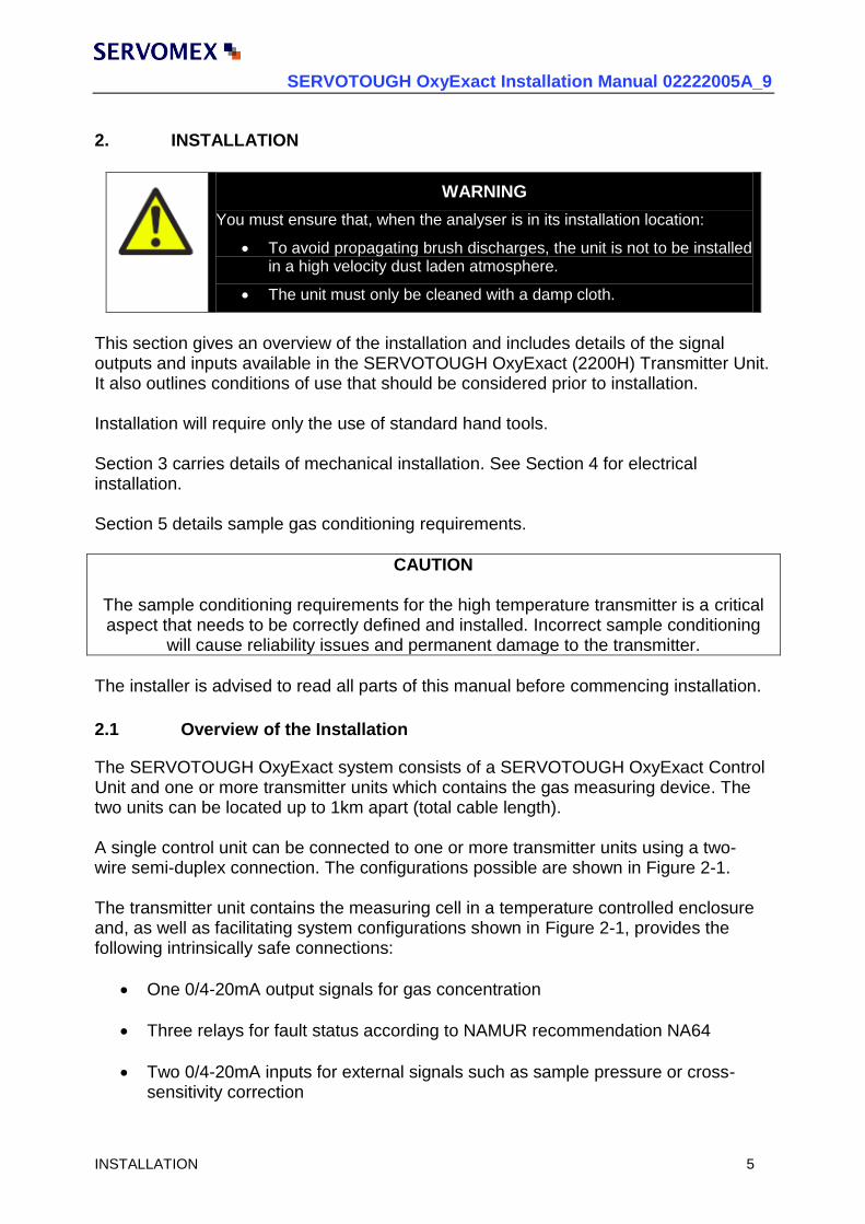
2. INSTALLATION
WARNING
You must ensure that, when the analyser is in its installation location:
To avoid propagating brush discharges, the unit is not to be installed in a high velocity dust laden atmosphere.
The unit must only be cleaned with a damp cloth.
This section gives an overview of the installation and includes details of the signal outputs and inputs available in the SERVOTOUGH OxyExact (2200H) Transmitter Unit. It also outlines conditions of use that should be considered prior to installation. Installation will require only the use of standard hand tools. Section 3 carries details of mechanical installation. See Section 4 for electrical installation. Section 5 details sample gas conditioning requirements.
CAUTION
The sample conditioning requirements for the high temperature transmitter is a critical aspect that needs to be correctly defined and installed. Incorrect sample conditioning
will cause reliability issues and permanent damage to the transmitter.
The installer is advised to read all parts of this manual before commencing installation.
2.1 Overview of the Installation The SERVOTOUGH OxyExact system consists of a SERVOTOUGH OxyExact Control Unit and one or more transmitter units which contains the gas measuring device. The two units can be located up to 1km apart (total cable length). A single control unit can be connected to one or more transmitter units using a two- wire semi-duplex connection. The configurations possible are shown in Figure 2-1. The transmitter unit contains the measuring cell in a temperature controlled enclosure and, as well as facilitating system configurations shown in Figure 2-1, provides the following intrinsically safe connections:
One 0/4-20mA output signals for gas concentration
Three relays for fault status according to NAMUR recommendation NA64
Two 0/4-20mA inputs for external signals such as sample pressure or cross-sensitivity correction

SERVOTOUGH OxyExact Installation Manual 02222005A_9
6 INSTALLATION
Four digital input signals for the status of associated external devices or initiating specific functions
Two connection pairs for external flow alarm devices The transmitter unit also requires connection to the electrical supply independent of a transmitter unit. Installation details in this manual do not include operation. See the Operator manual for this information.
Figure 2-1: Analyser system configurations
Key to Figure 2-1
1. Control unit connected to a single transmitter unit
2. Multiple transmitter units with the control unit terminating the
connecting cable
3. Multiple transmitter units with the transmitter units terminating
the connecting cable

SERVOTOUGH OxyExact Installation Manual 02222005A_9
INSTALLATION 7
2.2 Installation Location The equipment complies with EN 601010-1: 1993 (IEC 601010-1).
If the transmitter unit is to be installed in an area which may be hazardous due to the presence of flammable vapours or gases then any "Special Conditions for Safe Use" and/or "Schedules of Limitation", as detailed in the Safety Certification, must be followed. The degree of protection of the enclosure is IP66 and NEMA 4X. The SERVOTOUGH OxyExact (2200H) Transmitter Unit may only be wall mounted. The site chosen should be protected from extreme weather conditions. Consideration should be given to the effect of sun, rain, snow or wind on the ambient temperature rating. It may be necessary to install the unit in a protective enclosure. Ambient operating temperature range is -10°C to +50°C (14°F to 122°F). Ambient temperature fluctuations should be minimised for applications requiring a high precision measurement. If low ambient temperatures are expected then a heated enclosure may be required. There should be adequate room for installation and subsequently servicing the unit. The location should be reasonably vibration-free. Vibration of the transmitter unit may degrade the measurement precision. In applications where excessive vibration may be present, for example, on ships near large motors, consideration should be given to using anti-vibration mounts. Relative humidity <95%, non-condensing. The SERVOTOUGH OxyExact (2200H) Transmitter Unit is rated in accordance with IEC 664 for "Pollution Degree 2".
Where the installation is such that the enclosure ingress protection is maintained to IP66 (NEMA 4X) and covers remain securely fitted, the apparatus is suitable for use in locations where there may be significant deposits of dusts or fibres, (Pollution Degree 4) and/or where there may be drips, splashes of water or subjected to hose down.
The covers may be removed during installation or servicing only if there is negligible risk of pollution or contamination of the electronic circuits contained within the enclosures and the covers are securely replaced immediately after the operation is completed.
Altitude <3,000m (10,000ft)

SERVOTOUGH OxyExact Installation Manual 02222005A_9
8 INSTALLATION
2.3 Sample Gas Conditioning
CAUTION
The sample conditioning requirements for the high temperature transmitter is a critical component that needs to be correctly defined and installed.
Incorrect sample conditioning will cause reliability issues and permanent damage to the transmitter.
Heating of the sample interface must be considered to ensure the sample has no condensates within the inlet/outlet pipes.
The minimum requirement would be to control the sample gas pressure and flow rate. Depending on sample gas composition it may be necessary to remove condensate and particulate matter. When operating with high pressure (greater than 18psia, 124kPa) additional sample gas conditioning is required (see Section 5). It is envisaged that all sample conditioning requirements will have been considered prior to receipt of the unit, however, Section 5 of this manual includes information pertinent to the system design.
2.4 Electrical Supply Requirements The supply must be switched and fused external to the control unit. The electrical installation must comply with the requirements for the hazardous zone of the location and any local or national regulations. An electrical supply is required. The SERVOTOUGH OxyExact (2200H) Transmitter Unit is rated in accordance with IEC 664 for "Installation Category II". The SERVOTOUGH OxyExact (2200H) Transmitter Unit is designed for use with a "grounded neutral" supply and must also be connected to an external protective earthing system. Rated voltage range: The SERVOTOUGH OxyExact (2200H) Transmitter Unit is factory configured to operate over the range:
100V ac to 120V ac, or
220V ac to 240V ac The required range must be specified at time of order. The transmitter unit includes an internal replaceable fuse, rated at F 1.6Amp HRC and power consumption is 110VA max. The supply installation should be rated accordingly.

SERVOTOUGH OxyExact Installation Manual 02222005A_9
INSTALLATION 9
2.5 Signal Outputs/inputs All outputs and inputs are designed to form part of an intrinsically safe system. Configuration is changed via the digital communication port and any SERVOTOUGH OxyExact Control Unit may be used (refer to Operator manual).
2.5.1 Analog Output Board
The mA output is designed such that, whilst the hardware will limit maximum current to 21.5mA, under normal operation the output will not exceed 20.5mA.
Maximum load resistance – 600 ohms
500V minimum isolation voltage
According to NAMUR specification NE43 A number of features associated with the mA output may be configured:
1. The nominal output range may be set up to be 0 - 20 or 4 - 20mA and optionally reversed, i.e. 20 - 0 or 20 - 4mA.
2. The corresponding oxygen values at the nominal limits may be set to two decimal places within the range -25% to 150% oxygen (a minimum difference of 0.5% oxygen is recommended).
3. When a 4mA limit is selected, an absolute under range value may be set.
4. The output may be set to ‘Jam’ (either low; 0.00mA or high; 21.0mA) under transmitter fault conditions. The output will be 0.00mA when the transmitter is de-energised.
5. Under controlled calibration conditions (e.g. autocalibration), the output may be
set to ‘Freeze’ (i.e. the output will ‘not Follow’ the gas concentrations during calibration).
6. The oxygen measurement may have additional filtering imposed – this effects both the mA output and any digitally transmitted oxygen signal to the control unit.

SERVOTOUGH OxyExact Installation Manual 02222005A_9
10 INSTALLATION
2.5.2 Status Outputs
Three contact pairs exist for status signals that can be interrogated by an external system to transmit the operational status of the transmitter unit (the signals are also available at the control unit). The output rating of the contacts is dependent upon certification. Refer to Appendix 2. Status is defined in accordance with NAMUR recommendation NA64, i.e:
NAMUR NAS4
terminology Meaning OxyExact 2200
system display
"Breakdown" The measured signal is invalid due to
a fault on the transmitter unit or its
peripheral equipment
Fault
"Check request" The measured signal is still valid but the "attrition reserves" will soon be
used up.
Maintenance
required
"In service" Work is in progress on the transmitter unit
Service in
progress
Table 2-1: NAMUR NAS4 vs System Display
1. The function of the status outputs may not be re-assigned. 2. The contacts will be open circuit when de-energised. 3. Whilst the following may be customised, factory settings are configured such
that:
Transmitter status Status output designation
Output condition
Transmitter unit fault exists Fault Open
No transmitter unit fault exists Fault Closed
Maintenance required Maintenance Open
Maintenance not required Maintenance Closed
Transmitter unit operational Service Closed
Transmitter unit in service mode Service Open
Table 2-2: Status outputs – factory settings

SERVOTOUGH OxyExact Installation Manual 02222005A_9
INSTALLATION 11
2.5.3 Analog inputs
Two 0/4-20 mA input channels, non-isolated, primarily intended for signals from an external pressure transmitter or a signal for cross interference correction. These inputs are freely configurable in software and may also be used for re-transmission of other, externally generated, analog signals to the control unit.
2.5.4 External flow alarm inputs
Two channel pairs, non-isolated, for inductive/proximity type flow detectors, intrinsically safe in accordance with BS EN 50227 (DIN 19234/NAMUR).
Voltage: 8Vdc
Current: 8mA (max) Such sensors cannot be used with flowmeters using non-conductive floats, for example, ceramic.
2.5.5 Digital status inputs
External connections to four digital inputs, non-isolated, may be made. These may be configured to activate the SERVOTOUGH OxyExact Transmitter status functions, dependent upon an external event (e.g. alternative flow alarm) or assigned to specific transmitter action functions. Transmitter status functions are: Fault Maintenance Request Service in Progress Message All of these signals are relayed back to any control unit fitted. The message status is only reflected at the control unit whilst the Fault, Maintenance and Service functions also cause the relevant status output signals to be generated by the transmitter (reference 2.5.2) as well as any action on the transmitter analog output (reference 2.5.1) to be taken. Transmitter action functions are: Calibrate zero point Calibrate span point Whilst the following may be customised, as supplied, the following set-up is configured but not enabled. To activate the commands, the functions must be enabled within software and either momentary (between 0.5 and 1.5 seconds) or closed connections made: Input 1: Momentary Contact Calibrate Zero Input 2: Momentary Contact Calibrate Span Input 3: Closed Contact – set status to ’Service in Progress’” Input 4: Not Used
SERVOTOUGH OxyExact Installation Manual 02222005A_9
12 INSTALLATION
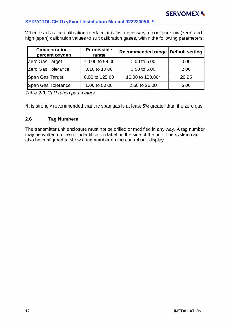
When used as the calibration interface, it is first necessary to configure low (zero) and high (span) calibration values to suit calibration gases, within the following parameters:
Concentration – percent oxygen
Permissible range
Recommended range Default setting
Zero Gas Target -10.00 to 99.00 0.00 to 5.00 0.00
Zero Gas Tolerance 0.10 to 10.00 0.50 to 5.00 2.00
Span Gas Target 0.00 to 125.00 10.00 to 100.00* 20.95
Span Gas Tolerance 1.00 to 50.00 2.50 to 25.00 5.00
Table 2-3: Calibration parameters
*It is strongly recommended that the span gas is at least 5% greater than the zero gas.
2.6 Tag Numbers The transmitter unit enclosure must not be drilled or modified in any way. A tag number may be written on the unit identification label on the side of the unit. The system can also be configured to show a tag number on the control unit display.

SERVOTOUGH OxyExact Installation Manual 02222005A_9
MECHANICAL INSTALLATION 13
3. MECHANICAL INSTALLATION
3.1 Unpacking and Inspection
WARNING
The control unit weighs approximately 16Kg (35lbs). Care must be taken when handling it.
Remove the SERVOTOUGH OxyExact (2200H) Transmitter Unit and accessories from their packing and inspect for any damage due to transit. (The enclosure has handholds on both sides to facilitate lifting). Do not rest the transmitter on the sample interface. The inlet/outlet pipes are protected, but it is good practise to lay the transmitter on its mounting lugs. If damage has occurred, inform Servomex or its agent immediately. Retain all packing and shipping information. Check that the supplied parts agree with the purchase specification. See also any Instrument Modification Sheets which may form part of this manual. Supplied parts:
One SERVOTOUGH OxyExact (2200H) Transmitter Unit
One accessories kit comprising: o Spare fuses o 2 x Allen key o 1 x Installation manual
(Other order specific items may also be included.)
3.2 Transmitter Unit Description The SERVOTOUGH OxyExact (2200H) Transmitter Unit is essentially an aluminium enclosure finished with a protective epoxy powder paint. All weatherproof seals are silicone rubber. The unit comprises three separate compartments (see Figure 3-1); Lower Right: An explosion proof enclosure for the power supply and intrinsic
safety components that supply electrical power to the rest of the unit. Connection to the electrical power supply is made inside the enclosure. Access to this enclosure is by releasing the locking screw in the explosion proof cover and unscrewing it anti(counter)-clockwise.
Upper Right: An enclosure for the signal processing electronics and all user
connections. The electronics are intrinsically safe. Access to this enclosure is by removing the 4 screws securing the cover.
SERVOTOUGH OxyExact Installation Manual 02222005A_9
14 MECHANICAL INSTALLATION
Left: A second enclosure containing the measuring cell and pressure transducer (option). Gas connections are made to this enclosure.
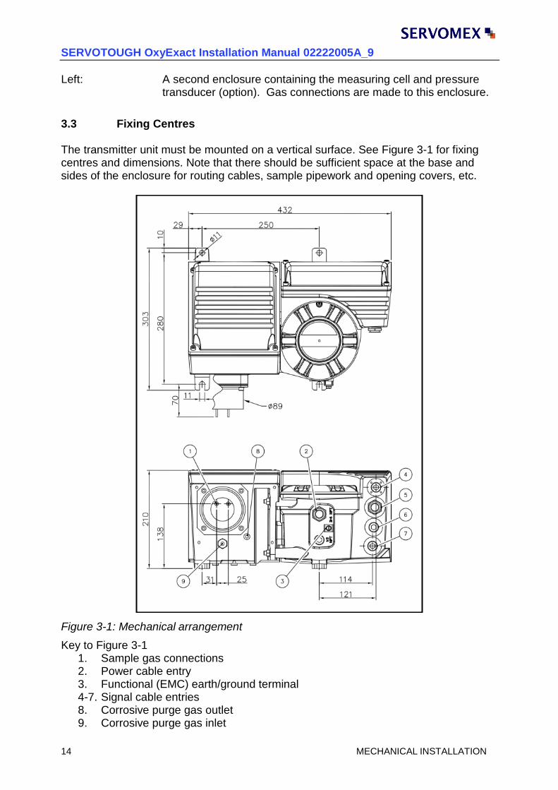
3.3 Fixing Centres The transmitter unit must be mounted on a vertical surface. See Figure 3-1 for fixing centres and dimensions. Note that there should be sufficient space at the base and sides of the enclosure for routing cables, sample pipework and opening covers, etc.
Figure 3-1: Mechanical arrangement
Key to Figure 3-1 1. Sample gas connections 2. Power cable entry 3. Functional (EMC) earth/ground terminal 4-7. Signal cable entries 8. Corrosive purge gas outlet 9. Corrosive purge gas inlet
SERVOTOUGH OxyExact Installation Manual 02222005A_9
ELECTRICAL INSTALLATION 15
4. ELECTRICAL INSTALLATION
WARNING
The Intrinsically Safe circuits described as “isolated” (TB01/2-7, TB01/8&9 and TB03/7-10) are galvanically
isolated for voltages up to 375V peak. The Intrinsically Safe circuits described as “isolated” (TB04/1-4, TB03/2-5 and
TB02/2-9) are connected to the earth reference of the apparatus. This must be taken into account in any
installation where the apparatus is used.
CAUTION
It is a condition of certification that the unit must be installed following the appropriate national or international legislation or codes of practice. In particular, the correct glands
must be fitted to cable entries and the weatherproofing of the enclosure must not be compromised.
To retain certification the unit must not be modified, mechanically or electrically.
Additional holes must not be drilled into any part of the unit's enclosure.
Insulation testing: to prevent damage to the transmitter unit it is necessary to disconnect cables being tested from the unit.
WARNING
The installation must conform to relevant safety requirements, National Electrical Code and any local
regulations. The installation must be safe for any extremes of operating conditions which may occur in the operating
environment of the analyser system.
4.1 CE Markings The SERVOTOUGH OxyExact oxygen analyser system complies with the European Directives on CE Marking (93/68/EEC) and Electromagnetic Compatibility (EMC 89/336/EEC).
CAUTION
To comply with the European Community Directives the interconnecting cables used for all signal inputs and outputs must be screened/shielded or equivalent protection
provided.
To comply with EMC emissions and susceptibility standards the functional earth/ ground must always be connected to a local EMC ground. This cable must not exceed
2 metres in length.

SERVOTOUGH OxyExact Installation Manual 02222005A_9
16 ELECTRICAL INSTALLATION
4.2 Glands and Cable Entries All cable entries must be fitted with appropriate glands or plugs to maintain the required weatherproofing of the enclosures. Whilst the SERVOTOUGH OxyExact has been tested to meet IP66 actual certification requirements are less onerous, however, as a minimum:
All entries to the enclosure must be sealed to meet IP20.
When used in a hazardous dust area, all entries to both enclosures must be sealed to meet IP6X.
Reminder: to maintain the full integrity of the transmitter unit all entries to both enclosures must be sealed to meet IP66. Power supply cable entry: 1 x 3/4" NPT Signal cable entries: 1 x 3/4" NPT and 3 x ½” NPT Accessories are available to convert to M20 or PG 13.5 and are supplied if ordered.
4.3 Identification and Location of Components See Figure 4-1 for location of terminal blocks, etc.

SERVOTOUGH OxyExact Installation Manual 02222005A_9
ELECTRICAL INSTALLATION 17
Figure 4-1: Electrical connections

SERVOTOUGH OxyExact Installation Manual 02222005A_9
18 ELECTRICAL INSTALLATION
4.4 Earth/ground Requirements For compliance with EMC standards the external functional (EMC) earth/ground terminal located on the external base of the unit (see Figure 3-1) must always be connected to a local earth/ground. The terminal is suitable for:
Flexible conductors - up to 10mm2
Solid conductors - up to 10mm2
WARNING
The transmitter unit contains intrinsically safe circuits. When the transmitter unit is installed in a hazardous area the safety
earth/ground must comply with relevant national or international standards to ensure a safe installation, whether by the electrical
supply or by a separate connection.
4.5 Electrical Power Supply Connection
WARNING
ATEX REQUIREMENTS Cable entry holes are provided as specified on the certified drawings
for the accommodation of suitable BASEEFA certified flameproof cable entry devices, with or without the interposition of a suitable
BASEEFA certified flameproof thread adaptor. Unused entries are to be fitted with suitable BASEEFA certified flameproof stopping plugs.
Suitable flameproof cable entry devices, thread adaptors and
stopping plugs certified as Equipment (not a Component) under an EC Type examination Certificate to Directive 94/9/EC may also be
used in the manner specified above.
CAUTION
The unit is factory configured to operate on either 100V ac to 120V ac or 220V ac to 240V ac. Refer to Section 2.4 for additional installation rating details.
Specific voltage rating information is given on the label located on the right-hand side of
the unit. Ensure that the unit is configured to operate on the correct supply voltage.
The unit does not include an integral switch for disconnecting the electrical supply. The installer must include a means of isolating electrical power by a switch or circuit breaker located close to the control unit. It must be marked as the disconnecting device for the
equipment.
The branch circuit supplying power to the control unit should be installed with a suitable fuse rated not greater than 15A or a suitable over current protection device set not
greater than 15A.

SERVOTOUGH OxyExact Installation Manual 02222005A_9
ELECTRICAL INSTALLATION 19
The electrical supply terminals are suitable for:
Flexible conductors - 0.5 to 1.5mm2 (20 to 16 AWG)
Solid conductors - 0.5 to 2.5 mm2 (20 to 14 AWG) Cables should be suitable for temperatures of at least 70°C. Connection is made to TB 05 located on the power supply unit (see Figure 4-1). Terminal order from the top is:
L - Live (AC)
N - Neutral (ACC)
- Protective earth/ground
4.6 Transmitter Unit to Control Unit Connection One or more transmitter units can be connected to a single control unit using a two-wire, semi-duplex, bi-polar connection. The possible system configurations are shown in Figure 2-1 earlier in this manual. This connection does not require the use of additional intrinsically safe barriers or interface devices, however, no other equipment connections are permitted. The maximum total cable length depends on cable parameters and certification conditions (refer to Appendix). However, typically, a single transmitter/control unit configuration may be separated by up to 1km of cable. Cable is to be a screened/shielded, twisted pair with the screen/shield connected to the control unit ground. The screen/shield must not be connected directly to the transmitter unit ground. The terminals are suitable for:
Flexible conductors - 0.5 to 1.5mm2 (20 to 16 AWG)
Solid conductors - 0.5 to 1.0mm2 (20 to 18 AWG) Cables should be suitable for temperatures of at least 70°C. Connection is made to TB 03 located on the signal processing board. To ensure that cables are dressed neatly it is recommended that a rearward gland hole is used. For a transmitter unit at the ‘end’ of the data connection cable, connections are made to:
TB 03 – 6 - screen/shield
TB 03 – 7 - ‘A’ from the cable
TB 03 – 8 - ‘B’ from the cable
SERVOTOUGH OxyExact Installation Manual 02222005A_9
20 ELECTRICAL INSTALLATION
For a transmitter unit located in the ‘middle’ of the data connection cable, connections are made to terminal numbers:
TB 03 – 6 - screen/shield from both cables
TB 03 – 7 - ‘A’ from cable 1
TB 03 – 8 - ‘B’ from cable 1
TB 03 – 9 - ‘A’ from cable 2
TB 03 – 10 - ‘B’ from cable 2
In order to avoid ground loops, the screen/shield termination is connected via a capacitance. There is therefore, no direct connection to ground for this cable within the transmitter.
The screen/shield will, however, be directly connected to ground at the control unit.
4.6.1 Cable Termination Switch
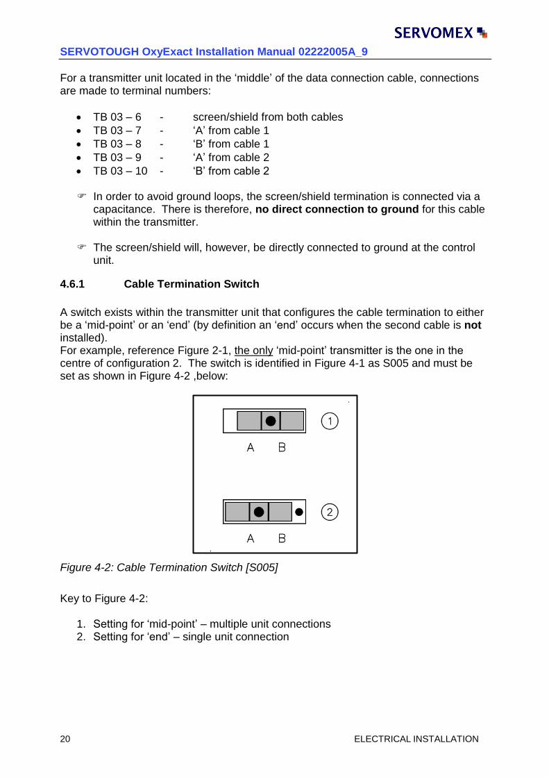
A switch exists within the transmitter unit that configures the cable termination to either be a ‘mid-point’ or an ‘end’ (by definition an ‘end’ occurs when the second cable is not installed). For example, reference Figure 2-1, the only ‘mid-point’ transmitter is the one in the centre of configuration 2. The switch is identified in Figure 4-1 as S005 and must be set as shown in Figure 4-2 ,below:
Figure 4-2: Cable Termination Switch [S005]
Key to Figure 4-2:
1. Setting for ‘mid-point’ – multiple unit connections 2. Setting for ‘end’ – single unit connection

SERVOTOUGH OxyExact Installation Manual 02222005A_9
ELECTRICAL INSTALLATION 21
4.6.2 Transmitter Unit Address Switch
The control unit ’recognises’ a transmitter by a unique address. This must be set up as part of the transmitter installation. If only one transmitter unit is fitted, the factory default setting will suffice and no further action is necessary. If more than one transmitter unit is connected to a single control unit, a switch exists within the transmitter to configure a discrete address. This rotary switch is identified, in Figure 4-1, as S0001 and must be set as shown in Figure 4-3, below:
Figure 4-3: Transmitter unit address switch [S001]
Switch position Function/Transmitter Transmitter identity as the control unit
0 Not used N/A
1 Factory default for 1 transmitter T01
2 Set for transmitter no. 2 if fitted T02
3 Set for transmitter no. 3 if fitted T03
4 Set for transmitter no. 4 if fitted T04
5 Set for transmitter no. 5 if fitted T05
6 Set for transmitter no. 6 if fitted T06
7 to F Not used N/A

SERVOTOUGH OxyExact Installation Manual 02222005A_9
22 ELECTRICAL INSTALLATION
4.7 Signal and Output/Input Connections
WARNING
ATEX REQUIREMENTS Cable entry holes are provided as specified on the certified drawings
for the accommodation of suitable BASEEFA certified flameproof cable entry devices, with or without the interposition of a suitable
BASEEFA certified flameproof thread adaptor. Unused entries are to be fitted with suitable BASEEFA certified flameproof stopping plugs.
Suitable flameproof cable entry devices, thread adaptors and
stopping plugs certified as Equipment (not a Component) under an EC Type examination Certificate to Directive 94/9/EC may also be
used in the manner specified above.
To comply with EMC standards, connections to signal outputs/inputs (with the exception of external flow alarm connections, reference Section 4.7.4) must use screened/shielded or shielded cable. This may be either separately screened/ shielded pairs or twisted pairs with an overall screen/shield. All terminals are suitable for: Flexible conductors - 0.5 to 1.5mm2 (20 to 16 AWG) Solid conductors - 0.5 to 1.0mm2 (20 to 18 AWG) Cables should be suitable for temperatures of at least 70°C.
WARNING
When the transmitter unit is installed in a hazardous area, these output/input signals must be connected to an intrinsically safe
system.
4.7.1 Analog Output
Reference Section 2.5.1.
CAUTION
These connections are part of an intrinsically safe system and must only be connected to a suitable, intrinsically safe certified, interface device. Refer to the appropriate
certification documents (see Appendix 2).
Connection is made to TB 01 on the signal processor board. To ensure that cables are dressed neatly it is recommended that a rearward gland hole is used. TB 01 – 1 - screen/shield TB 01 – 8 - +ve 0/4 – 20mA output TB 01 – 9 - -ve 0/4 – 20mA output

SERVOTOUGH OxyExact Installation Manual 02222005A_9
ELECTRICAL INSTALLATION 23
4.7.2 Status Outputs
Reference Section 2.5.2.
CAUTION
These connections are part of an intrinsically safe system and must only be connected to a suitable, intrinsically safe certified, interface device. Refer to the appropriate
certification documents (see Appendix 2).
Connection is made to TB 01 on the signal processor board. To ensure that cables are dressed neatly it is recommended that a rearward gland hole is used. TB 01 – 1 - screen/shield TB 01 – 2 - +ve fault TB 01 – 3 - -ve fault TB 01 – 4 - +ve maintenance TB 01 – 5 - -ve maintenance TB 01 – 6 - +ve service TB 01 – 7 - -ve service
4.7.3 Analog Inputs
Reference Section 2.5.3.
CAUTION
These connections are part of an intrinsically safe system and must only be connected to a suitable, intrinsically safe certified, ISOLATING interface device. Refer to the
appropriate certification documents (see Appendix 2).
Connection is made to TB 03 on the electronics board. To ensure that cables are dressed neatly it is recommended that a rearward gland hole is used. TB 03 – 1 - screen/shield TB 03 – 2 - +ve input 1 TB 03 – 3 - -ve input 1 (connected to ground (earth)) TB 03 – 4 - +ve input 2 TB 03 – 5 - -ve input 2 (connected to ground (earth)
SERVOTOUGH OxyExact Installation Manual 02222005A_9
24 ELECTRICAL INSTALLATION
4.7.4 External Flow Alarm Inputs
Reference Section 2.5.4.
CAUTION
These cables do not require to be screened. To comply with EMC performance, these cables must not exceed 2 metres in length.
Connection is made to TB 04 on the signal processor board. To ensure that cables are dressed neatly it is recommended that a rearward gland hole is used. TB 04 – 1 - +ve status signal 2 TB 04 – 2 - -ve status signal 2 (connected to ground/earth) TB 04 – 3 - +ve status signal 1 TB 04 – 4 - -ve status signal 1 (connected to ground/earth)
4.7.5 Digital Status Inputs
Reference Section 2.5.5.
CAUTION
These connections are part of an intrinsically safe system and must only be connected to a suitable, intrinsically safe certified, ISOLATING interface device. Refer to the
appropriate certification documents (see Appendix 2).
Connection to external contact pairs is made to TB 02 on the electronics board. To ensure that cables are dressed neatly it is recommended that a rearward gland hole is used. TB 02 – 1 - screen/shield TB 02 – 2 - +ve status input 1 TB 02 – 3 - -ve status input 1 (connected to ground (earth)) TB 02 – 4 - +ve status input 2 TB 02 – 5 - -ve status input 2 (connected to ground (earth)) TB 02 – 6 - +ve status input 3 TB 02 – 7 - -ve status input 3 (connected to ground (earth)) TB 02 – 8 - +ve status input 4 TB 02 – 9 - -ve status input 4 (connected to ground (earth)) TB 02 – 10 - no connection

SERVOTOUGH OxyExact Installation Manual 02222005A_9
AUTOCALIBRATION OPTIONS 25
5. SAMPLE GAS CONDITIONING AND CONNECTION
CAUTION
The SERVOTOUGH OxyExact (02200H) Transmitter can be factory set with different measurement cell temperatures. The cell temperature will be set between 65°C and
110°C depending on the version ordered.
Hence, the sample conditioning systems must be designed with regards to each Transmitter unit and its cell temperature set point.
A sample conditioning system is required to:
Control the flow and pressure of the sample gas to the analyser
Dry the gas to remove water and/or condensate
Remove particulate matter
Provide facilities for calibration gases for the analyser
Protect the transmitter from abnormal sample conditions
Incorporate solenoid valves for autocalibration (option)
Incorporate a calibration facility for pressure compensation (option) Correct conditioning and control of sample gases will greatly improve the accuracy and reliability of the analyser. Historically, most analyser faults are caused by inadequate sample conditioning. It is recommended that the internal volume of the sample pipework and fittings (filters, etc.) is kept to a minimum to optimise response time. Servomex or their agents can design and supply a suitable sample conditioning system.
WARNING
DANGER OF SAMPLE GASES Sample and calibration gases may be flammable, toxic or asphyxiant. Gases must be vented to an area where they will not be a hazard to
personnel.
5.1 Sample Wetted Materials A full list of materials in contact with the sample will depend on options ordered. In all instances the sample gas must be compatible with the following materials:
Borosilicate glass
Nickel
Platinum
Platinum/iridium alloy
PTFE
Chemraz
316 stainless steel

SERVOTOUGH OxyExact Installation Manual 02222005A_9
26 AUTOCALIBRATION OPTIONS
In addition
The internal flow alarm adds yttria stabilised zirconia to the list
CAUTION
If acid gases are being analysed the presence of moisture in the sample gas may lead to corrosion of the measuring system. The sample must be dried to a moisture
content below which such corrosion will not occur. It may be advisable to fit a moisture sensor to provide an alarm should this drying system fail.
5.2 Sample Gas Conditions Flow Rate: The transmitter unit offers two flow configurations, specified at time of order: Low flow rate - 100 to 250ml/minute Condition:
Free from liquid condensate Particulates size <3 micron Sample temperature dependant of cell set point temperature Sample dew-point must be at least 5°C below cell set point temperature
Pressure 0.3kPa (50mm wg) relative to outlet pressure Maximum internal pressure: 45 psia (310kPaa) The measuring cell flow rate and internal pressure must not exceed the above values otherwise damage to the measuring cell can occur. Sample Vent
The oxygen signal is directly proportional to sample gas pressure in the measuring cell.
The sample gas exhaust connection to the transmitter unit should not be restricted and be of adequate diameter such that a back pressure is not created. Special consideration should be given if the exhaust is taken to a vent header and not vented directly to atmosphere.
5.3 Sample gas connection Sample gas connections are made to the base of the transmitter unit. See Figure 3-1. The fittings are 1/8" NPT(F).

SERVOTOUGH OxyExact Installation Manual 02222005A_9
AUTOCALIBRATION OPTIONS 27
5.4 Calibration gas facilities Two calibrating gases are required. Ideally calibration gases should be at the same pressure and flow as the sample gases. The oxygen concentrations of the calibration gases may be application dependent. However, the following are recommended for use with the SERVOTOUGH OxyExact Transmitter:
Nitrogen, typically 0% oxygen (used as the ’low’ oxygen gas)
Air, typically 20.95% oxygen (used as the ’high’ oxygen gas) See the Operator manual for further guidance on the correct choice of gases. It is suggested a ‘fast loop’ is used to minimise response times and eliminate ‘dead legs’. Gas selection valves should be placed as close to the transmitter unit as possible. Calibration solenoid valves The transmitter does not include electrical connections for solenoid valves. Autocalibration is available when used in conjunction with a Servomex Control Unit. All associated electrical connections are made to the control unit. Internal Flow Alarm If fitted, the internal flow alarm is usually calibrated at a known sample gas flowrate. Therefore, a means of monitoring the actual flow into the transmitter will be required.

SERVOTOUGH OxyExact Installation Manual 02222005A_9
28 AUTOCALIBRATION OPTIONS
5.5 High Pressure Operation
WARNING
The SERVOTOUGH OxyExact Transmitter may be used with sample gas pressures in excess of 18psia, however, this must be specified
at the time of order.
Such units will have a factory fitted vent or ‘breather’ underneath the left hand enclosure – reference Figure 3-1.
Under no circumstances is the sample pressure allowed to exceed 45 psia (310 kPaa). If the sample gas pressure exceeds 18psia (124kPaa), the following precautions must be taken:
1. A relief valve set to 45 psia (310 kPaa) must be sited at the inlet to the sample system.
2. A non-return valve must be sited in the system return to process line.
3. The sample gas flow should be limited such that, in the event of a leak, the flow
rate to the analyser cannot exceed 2l/min.
5.6 Corrosive sample purge If the sample is corrosive it is recommended that a dilution purge is fitted to the measuring cell compartment. This will reduce the possibility of damage should there be a leak of sample gas. Gas connection is made to the base of the transmitter unit. See Figure 3-1. The fitting is 1/8" NPT (F). Purge gas should be inert gas or clean, dry air. Maximum flow rate is 50 ml/min.
5.7 Leak test Before commissioning it is recommended that the complete gas system is leak tested. When pressurising the system, ensure that the sample gas inlet and outlet are coupled together and raise the pressure slowly to prevent potential damage to the measuring cell.

SERVOTOUGH OxyExact Installation Manual 02222005A_9
INSTALLATION CHECKLIST 29
6. INSTALLATION CHECK LIST
Following completion of the installation procedure check:
Item Checked
Unit is firmly mounted
Supply voltage agrees with unit supplied
The unit is correctly earthed/grounded
Connection is made to control unit
Connection is made to analog outputs (as required)
Connection is made to analog inputs (as required)
Connection is made to alarm relays (as required)
Connection is made to digital inputs (as required)
Sockets are secured to their relevant boards
All wiring terminations are tightened
Screws in unused terminals are tightened
Cable glands are secured and made weather-tight
Cables are dressed neatly within the control unit
Inner door is secured (control unit)
Hazardous area safety requirements are complied with
External electrical connections are labelled
Covers are secured and weatherproof
Sample gas connections are labelled
Sample gas system is leak free
Table 6-1: Installation checklist
It is now possible to apply power to the unit. See the Operator manual for commissioning and operating the unit.
CAUTION
On powering up and connection to the control unit, check the cell temperature set point on the display and make a note of it. This WILL be the actual set point of the cell
temperature.

SERVOTOUGH OxyExact Installation Manual 02222005A_9
30 APPENDIX 1 – TECHNICAL SPECIFICATION
7. ROUTINE MAINTENANCE
Aside from routine calibration (refer to Operator manual) the SERVOTOUGH OxyExact Transmitter Unit requires minimal routine maintenance.
WARNING
The unit must only be cleaned with a damp cloth.
In very dusty environments, it will be prudent to occasionally clean off the outer surfaces using a damp cloth.
Emphasis is placed on ensuring that the sample gas remains clean and dry, consequently it is of greater importance to check that the associated sample system is adequately maintained.
Spares The SERVOTOUGH OxyExact (02200H) Transmitter Unit contains no parts that require routine service. Refer to the Service manual for full service instructions.

SERVOTOUGH OxyExact Installation Manual 02222005A_9
APPENDIX 1 – TECHNICAL SPECIFICATION 31
APPENDIX 1 TECHNICAL SPECIFICATION
FUNCTIONAL
Power supply: Either 100-120V ac 50/60Hz, -10% and +10%. or 220-240V ac 50/60Hz, -15% and +10%. Power required: 110VA Physical: Width: 432mm
Height: 260mm (360mm including sample interface) Depth: 210mm Weight: 16kg
ENVIRONMENTAL General: Suitable for indoor and sheltered outdoor locations Ingress protection: IP66 and Type 4X (NEMA 250) Operating temperature: -10 to 50°C (14°F to 122°F), in sheltered location Storage temperature: -20 to 70°C (-4°F to 158°F) Relative humidity: 95% RH maximum, non-condensing
Atmospheric pressure: 76 to 112 kPaa (11 to 16.2 psia)
Altitude: 3000m (10,000 feet) maximum
Installation category: II - in accordance with IEC 664 Pollution degree: 2 - in accordance with IEC 664 Warm up time: Typically 4 hours from cold start at 20°C

SERVOTOUGH OxyExact Installation Manual 02222005A_9
32 APPENDIX 1 – TECHNICAL SPECIFICATION
PERFORMANCE Unit is targeted to measure oxygen in the range 0 to 21%.
Intrinsic error (accuracy): <0.04% oxygen
Linearity: <0.02% oxygen (‘inherently linear’)
Repeatability: 0.03% oxygen
Response time (T90): Less than 4 s at 250ml/min
Zero drift1: < 0.08% oxygen per week
Span drift: < 0.1% oxygen per week
mA output:
Resolution: 0.001% oxygen or 0.002% of output span, whichever is the greater
Noise: 0.02% oxygen peak to peak within any 5 minute period
Effect of ambient temp: ±0.02% oxygen ±0.2 % of reading per 10°C
Sample flow effect: <0.1% oxygen change over the range 0-250ml/min
Effect of barometric or sample pressure:
Output reading is directly proportional to the absolute pressure at the sample vent of the analyser.
Effect of supply voltage Variation:
A 10% change of the supply voltage within the specified range will cause the output to change by less than 0.02% oxygen or 0.2% of reading, whichever is greater.
Attitude sensitivity: Less than 0.01% oxygen per degree of tilt
Vibration: Tested in accordance with En 50104
Internal Flow Alarm2 3:
Reproducibility: <5% of full scale
T90: <20 seconds
1 Published specification attained after two weeks operation under Process Conditions
2 Not suitable for use with gas mixtures that contain Hydrogen and/or Helium at concentrations over 10%
of the total mixture. 3 The specification of the Flow Alarm is based upon a sample gas of Air at 20°C and nominal
atmospheric pressure of 101kPaa.

SERVOTOUGH OxyExact Installation Manual 02222005A_9
APPENDIX 2 - CERTIFICATES 33
APPENDIX 2 CERTIFICATION
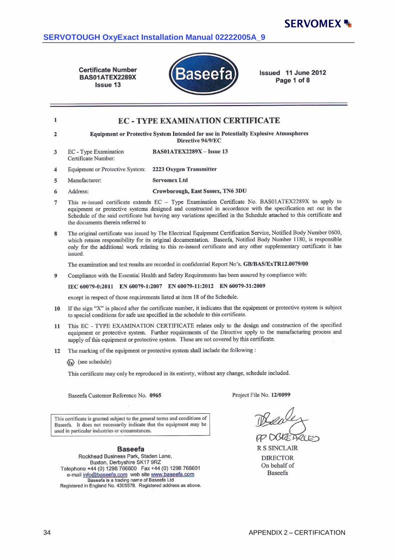
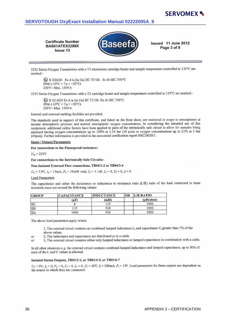
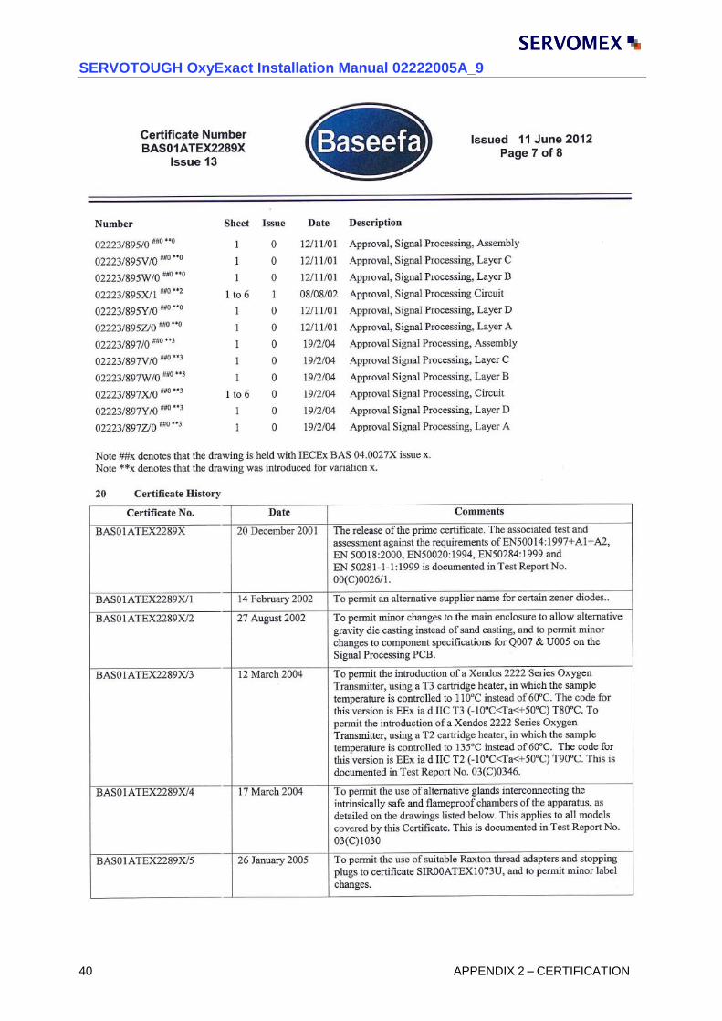
The following pages contain the ATEX certificate for this analyser. It details conditions of safe use and important parameters that shall be followed for safe installation.
SERVOTOUGH OxyExact Installation Manual 02222005A_9
34 APPENDIX 2 – CERTIFICATION

SERVOTOUGH OxyExact Installation Manual 02222005A_9
APPENDIX 2 - CERTIFICATES 35
SERVOTOUGH OxyExact Installation Manual 02222005A_9
36 APPENDIX 2 – CERTIFICATION

SERVOTOUGH OxyExact Installation Manual 02222005A_9
APPENDIX 2 - CERTIFICATES 37

SERVOTOUGH OxyExact Installation Manual 02222005A_9
38 APPENDIX 2 – CERTIFICATION

SERVOTOUGH OxyExact Installation Manual 02222005A_9
APPENDIX 2 - CERTIFICATES 39
SERVOTOUGH OxyExact Installation Manual 02222005A_9
40 APPENDIX 2 – CERTIFICATION

SERVOTOUGH OxyExact Installation Manual 02222005A_9
APPENDIX 2 - CERTIFICATES 41

This page intentionally blank