Embed Size (px)
Citation preview

1
Advanced Manufacturing Laboratory
Department of Industrial Engineering
Sharif University of Technology
Session # 1
PLC
This training introduces the basic hardware and software components of a
Programmable Controller (PLC). It details the architecture and basic
instruction set common to all PLC’s. Basic programming techniques and logic
designs are covered. This training describes the operating features of the PLC,
the advantages of the PLC over hard-wired control systems, practical
applications, troubleshooting and maintenance of PLC’s.
Advanced Manufacturing Laboratory, Department of Industrial Engineering, Sharif University of Technology
Manufacturing Lab, PLC (21-410), Session #1
2
2
History of Programmable Controllers
Relay Ladder Logic
Central Processing Unit
Input/Output System
Programming and Peripheral Devices
Programming Concepts
Applications
Advanced Manufacturing Laboratory, Department of Industrial Engineering, Sharif University of Technology
Manufacturing Lab, PLC (21-410), Session #1
3
Developed to replace relays in the late 1960s
Costs dropped and became popular by 1980s
Now used in many industrial designs
Advanced Manufacturing Laboratory, Department of Industrial Engineering, Sharif University of Technology
Manufacturing Lab, PLC (21-410), Session #1
4

3
The Hydramatic Division of the General Motors Corporation specified the
design criteria for the first programmable controller in 1968
Their primary goal was to eliminate the high costs associated with inflexible,
relay-controlled systems.
Advanced Manufacturing Laboratory, Department of Industrial Engineering, Sharif University of Technology
Manufacturing Lab, PLC (21-410), Session #1
5
1968 Programmable concept developed
1969 Hardware CPU controller, with logic instructions, 1 K of
memory and 128 I/O points
1974 Use of several (multi) processors within a PLC - timers and
counters; arithmetic operations; 12 K of memory and 1024 I/O points
1976 Remote input/output systems introduced
1977 Microprocessors - based PLC introduced
Advanced Manufacturing Laboratory, Department of Industrial Engineering, Sharif University of Technology
Manufacturing Lab, PLC (21-410), Session #1
6

4
1980 Intelligent I/O modules developed enhanced communications
facilities, enhanced software features (e.g. documentation), use of personal
microcomputers as programming aids
1983 Low - cost small PLC’s introduced
1985 on Networking of all levels of PLC, computer and machine
using SCADA software.
Advanced Manufacturing Laboratory, Department of Industrial Engineering, Sharif University of Technology
Manufacturing Lab, PLC (21-410), Session #1
7
Less wiring.
Wiring between devices and relay contacts are done in the PLC program.
Easier and faster to make changes.
Trouble shooting aids make programming easier and reduce downtime.
Reliable components make these likely to operate for years before failure.
Advanced Manufacturing Laboratory, Department of Industrial Engineering, Sharif University of Technology
Manufacturing Lab, PLC (21-410), Session #1
8
5
A digitally operating electronic apparatus which
uses a programming memory for the internal storage of instructions
for implementing specific functions such as
logic, sequencing, timing, counting and arithmetic to control
through digital or analog modules, various types of machines or
process.
Advanced Manufacturing Laboratory, Department of Industrial Engineering, Sharif University of Technology
Manufacturing Lab, PLC (21-410), Session #1
9
AMERICAN 1. Allen Bradley
2. Gould Modicon
3. Texas Instruments
4. General Electric
5. Westinghouse
6. Cutter Hammer
7. Square D
EUROPEAN 1. Siemens
2. Klockner & Mouller
3. Festo
4. Telemechanique
JAPANESE 1. Toshiba
2. Omron
3. Fanuc
4. Mitsubishi
Advanced Manufacturing Laboratory, Department of Industrial Engineering, Sharif University of Technology
Manufacturing Lab, PLC (21-410), Session #1
10

6
Manufacturing / Machining
Food / Beverage
Metals
Power
Mining
Petrochemical / Chemical
Advanced Manufacturing Laboratory, Department of Industrial Engineering, Sharif University of Technology
Manufacturing Lab, PLC (21-410), Session #1
11
1. SMALL - it covers units with up to 128 I/O’s and
memories up to 2 Kbytes.
- these PLC’s are capable of providing simple to advance
levels or machine controls.
2. MEDIUM - have up to 2048 I/O’s and memories up to 32 Kbytes.
3. LARGE - the most sophisticated units of the PLC family.
They have up to 8192 I/O’s and memories up to 750 Kbytes.
- can control individual production processes or entire
plant.
Advanced Manufacturing Laboratory, Department of Industrial Engineering, Sharif University of Technology
Manufacturing Lab, PLC (21-410), Session #1
12

7
Advanced Manufacturing Laboratory, Department of Industrial Engineering, Sharif University of Technology
Manufacturing Lab, PLC (21-410), Session #1
13
A
B
C
FS
MOTOR
TIMER
FLOAT SWITCH
SOLENOIDS
SOLENOID
1 -MINUTE
A tank is used to mix two liquids. The control circuit operates as follows:
1. When the start button is pressed, solenoids A and B energize. This permits
the two liquids to begin filling the tank.
2. When the tank is filled, the float switch trips. This de-energizes solenoids A
and B and starts the motor used to mix the liquids together.
3. The motor is permitted to run for one minute. After one minute has elapsed,
the motor turns off and solenoid C energizes to drain the tank.
Advanced Manufacturing Laboratory, Department of Industrial Engineering, Sharif University of Technology
Manufacturing Lab, PLC (21-410), Session #1
14
8
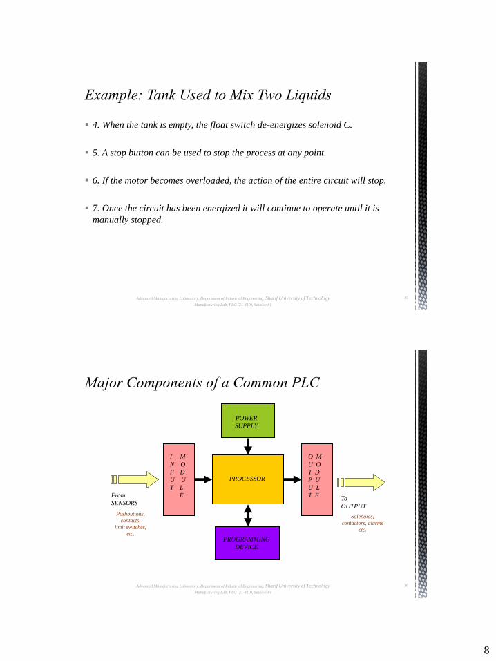
4. When the tank is empty, the float switch de-energizes solenoid C.
5. A stop button can be used to stop the process at any point.
6. If the motor becomes overloaded, the action of the entire circuit will stop.
7. Once the circuit has been energized it will continue to operate until it is
manually stopped.
Advanced Manufacturing Laboratory, Department of Industrial Engineering, Sharif University of Technology
Manufacturing Lab, PLC (21-410), Session #1
15
Advanced Manufacturing Laboratory, Department of Industrial Engineering, Sharif University of Technology
Manufacturing Lab, PLC (21-410), Session #1
16
PROCESSOR
POWER
SUPPLY
I M
N O
P D
U U
T L
E
O M
U O
T D
P U
U L
T E
PROGRAMMING
DEVICE
From
SENSORS
Pushbuttons,
contacts,
limit switches,
etc.
To
OUTPUT
Solenoids,
contactors, alarms
etc.
9
Advanced Manufacturing Laboratory, Department of Industrial Engineering, Sharif University of Technology
Manufacturing Lab, PLC (21-410), Session #1
17
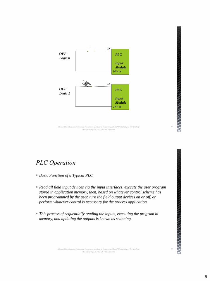
OFF
Logic 0
IN
PLC
Input
Module 24 V dc
OFF
Logic 1
IN
PLC
Input
Module
24 V dc
Basic Function of a Typical PLC
Read all field input devices via the input interfaces, execute the user program
stored in application memory, then, based on whatever control scheme has
been programmed by the user, turn the field output devices on or off, or
perform whatever control is necessary for the process application.
This process of sequentially reading the inputs, executing the program in
memory, and updating the outputs is known as scanning.
Advanced Manufacturing Laboratory, Department of Industrial Engineering, Sharif University of Technology
Manufacturing Lab, PLC (21-410), Session #1
18
10
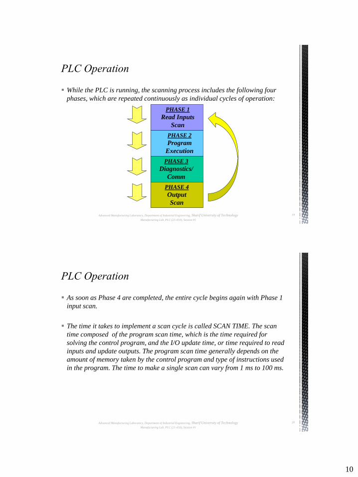
While the PLC is running, the scanning process includes the following four
phases, which are repeated continuously as individual cycles of operation:
Advanced Manufacturing Laboratory, Department of Industrial Engineering, Sharif University of Technology
Manufacturing Lab, PLC (21-410), Session #1
19
PHASE 2
Program
Execution
PHASE 3
Diagnostics/
Comm
PHASE 4
Output
Scan
PHASE 1
Read Inputs
Scan
As soon as Phase 4 are completed, the entire cycle begins again with Phase 1
input scan.
The time it takes to implement a scan cycle is called SCAN TIME. The scan
time composed of the program scan time, which is the time required for
solving the control program, and the I/O update time, or time required to read
inputs and update outputs. The program scan time generally depends on the
amount of memory taken by the control program and type of instructions used
in the program. The time to make a single scan can vary from 1 ms to 100 ms.
Advanced Manufacturing Laboratory, Department of Industrial Engineering, Sharif University of Technology
Manufacturing Lab, PLC (21-410), Session #1
20
11
begin
Input
Output
Resolve logic
Idle
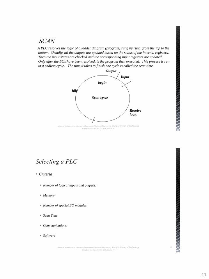
A PLC resolves the logic of a ladder diagram (program) rung by rung, from the top to the
bottom. Usually, all the outputs are updated based on the status of the internal registers.
Then the input states are checked and the corresponding input registers are updated.
Only after the I/Os have been resolved, is the program then executed. This process is run
in a endless cycle. The time it takes to finish one cycle is called the scan time.
Scan cycle
Advanced Manufacturing Laboratory, Department of Industrial Engineering, Sharif University of Technology
Manufacturing Lab, PLC (21-410), Session #1
Criteria
Number of logical inputs and outputs.
Memory
Number of special I/O modules
Scan Time
Communications
Software
Advanced Manufacturing Laboratory, Department of Industrial Engineering, Sharif University of Technology
Manufacturing Lab, PLC (21-410), Session #1
22
12
Understand the process
Hardware/software selection
Develop ladder logic
Determine scan times and memory requirements
Advanced Manufacturing Laboratory, Department of Industrial Engineering, Sharif University of Technology
Manufacturing Lab, PLC (21-410), Session #1
23
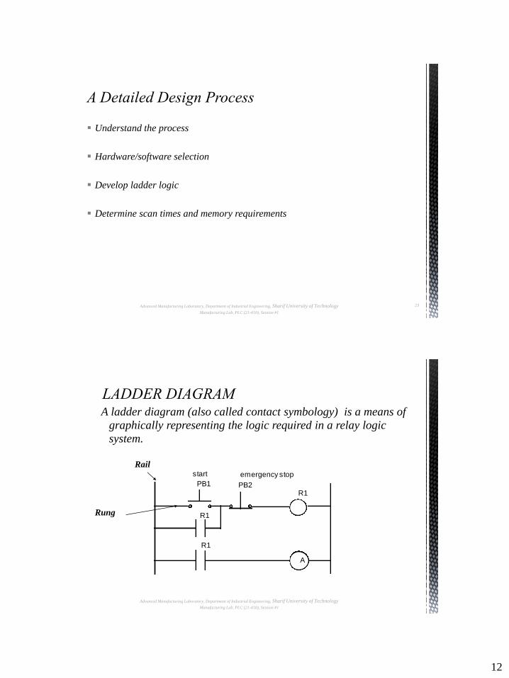
A ladder diagram (also called contact symbology) is a means of
graphically representing the logic required in a relay logic
system.
A
R1
PB1 PB2
R1
R1
start emergency stop
Rail
Rung
Advanced Manufacturing Laboratory, Department of Industrial Engineering, Sharif University of Technology
Manufacturing Lab, PLC (21-410), Session #1
13
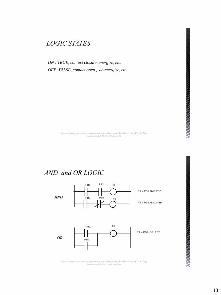
ON : TRUE, contact closure, energize, etc.
OFF: FALSE, contact open , de-energize, etc.
Advanced Manufacturing Laboratory, Department of Industrial Engineering, Sharif University of Technology
Manufacturing Lab, PLC (21-410), Session #1
PB1 R1PB2
R2
R1 = PB1.AND.PB2 R2 = PB2.AND.~PB4
PB3 PB4
PB1 R1
PB2
R1 = PB1 .OR. PB2
AND
OR
Advanced Manufacturing Laboratory, Department of Industrial Engineering, Sharif University of Technology
Manufacturing Lab, PLC (21-410), Session #1

14
R1 = PB1 .OR. (PB2 .AND. PB3)
PB1 R1
PB2 pb3
Advanced Manufacturing Laboratory, Department of Industrial Engineering, Sharif University of Technology
Manufacturing Lab, PLC (21-410), Session #1
Blocks are built from small ladder logic subroutines and used through the code as user defined ladder logic instructions, the advantages of this approach is the reduction of repetitive ladder logic code.
Sequential Function Chart (SFC) programming is similar to programming by computer flow chart. In SFC the program advances step by step through various blocks (where action happens such as a motor is started).
Transition conditions determine when the program advances from one block to another.
Both the action blocks and the transition conditions are created using ladder diagrams.
Structured text, uses simple instructions common to medium level programming languages: If , While, Then etc.
Note: Some programming packages allow the user to switch between Relay
Ladder Logic and Structured text representations of the code.
Advanced Manufacturing Laboratory, Department of Industrial Engineering, Sharif University of Technology
Manufacturing Lab, PLC (21-410), Session #1
15
Part
microswitch
Bar code reader
Stopper
Conveyor
MachineRobot
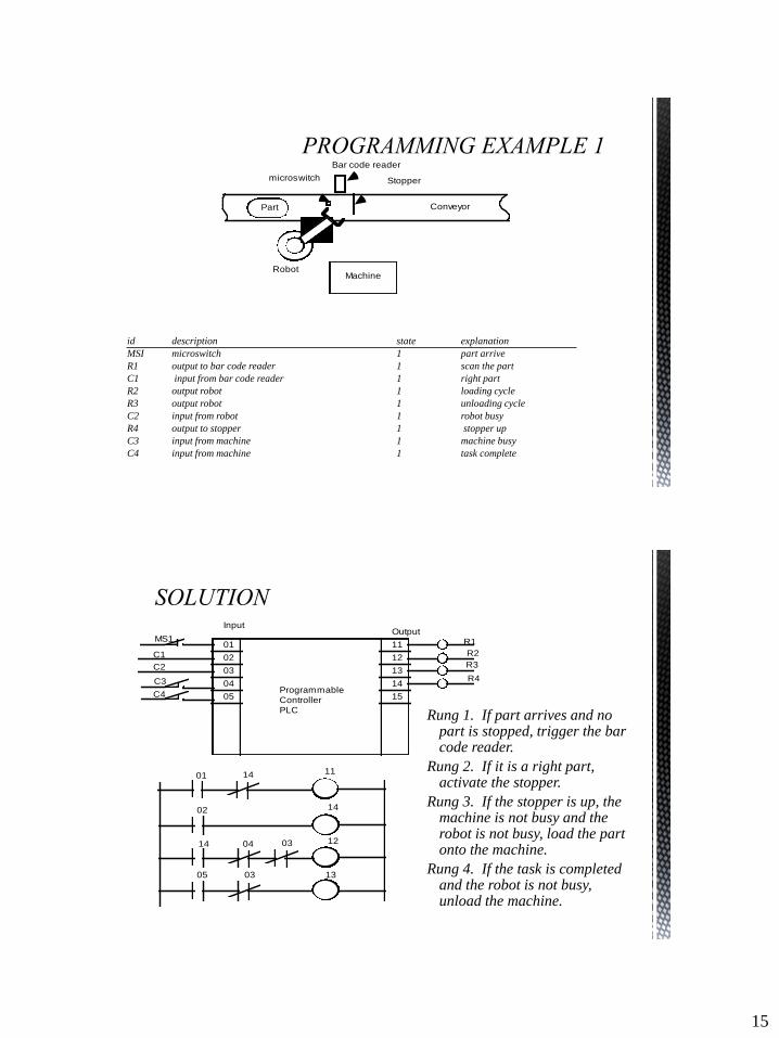
id description state explanation
MSI microswitch 1 part arrive
R1 output to bar code reader 1 scan the part
C1 input from bar code reader 1 right part
R2 output robot 1 loading cycle
R3 output robot 1 unloading cycle
C2 input from robot 1 robot busy
R4 output to stopper 1 stopper up
C3 input from machine 1 machine busy
C4 input from machine 1 task complete
01
02
03
04
05
11
12
13
14
15
InputOutput
Programmable Controller PLC
MS1
C1
C2
C3
C4
R1
R2
R3
R4
01 14 11
02
14 04 03
14
12
1305 03
Rung 1. If part arrives and no part is stopped, trigger the bar code reader.
Rung 2. If it is a right part, activate the stopper.
Rung 3. If the stopper is up, the machine is not busy and the robot is not busy, load the part onto the machine.
Rung 4. If the task is completed and the robot is not busy, unload the machine.