Embed Size (px)
Citation preview

Session 6 Groundwater Basics
Session 6 Agenda: Groundwater Basics
Introduction
Groundwater Monitoring Plan
Groundwater Characteristics
Monitoring System Design and Construction
Monitoring System Construction
Sampling and Analysis
Introduction
Ultimate Goal– Evaluate adequacy of groundwater monitoring requirements
for RCRA Permit Application
Session Goal– Highlight basic groundwater principles to improve
understanding of groundwater monitoring requirements and ultimately ensure that the groundwater monitoring plan is capable of early detection of a release from a unit
Groundwater Basics
TechnicalApproach/
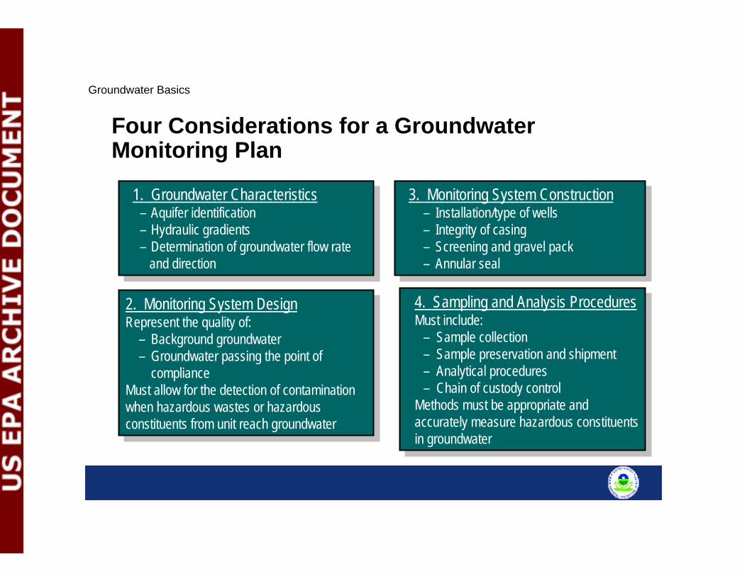
Major IssuesFour Considerations for a Groundwater Monitoring PlanFour Considerations for a Groundwater Monitoring Plan
2. Monitoring System DesignRepresent the quality of:
– Background groundwater – Groundwater passing the point of
complianceMust allow for the detection of contaminationwhen hazardous wastes or hazardousconstituents from unit reach groundwater
2. Monitoring System DesignRepresent the quality of:
– Background groundwater – Groundwater passing the point of
complianceMust allow for the detection of contaminationwhen hazardous wastes or hazardousconstituents from unit reach groundwater
4. Sampling and Analysis ProceduresMust include:
– Sample collection– Sample preservation and shipment– Analytical procedures– Chain of custody control
Methods must be appropriate and accurately measure hazardous constituents in groundwater
4. Sampling and Analysis ProceduresMust include:
– Sample collection– Sample preservation and shipment– Analytical procedures– Chain of custody control
Methods must be appropriate and accurately measure hazardous constituents in groundwater
1. Groundwater Characteristics – Aquifer identification– Hydraulic gradients– Determination of groundwater flow rate
and direction
1. Groundwater Characteristics – Aquifer identification– Hydraulic gradients– Determination of groundwater flow rate
and direction
3. Monitoring System Construction– Installation/type of wells– Integrity of casing– Screening and gravel pack– Annular seal
3. Monitoring System Construction– Installation/type of wells– Integrity of casing– Screening and gravel pack– Annular seal
Groundwater Basics
Groundwater CharacteristicsAquifer Identification– Confined– Unconfined– Perched– Semi-confined
Groundwater flow rates– Hydraulic conductivity
– Hydraulic gradient• Vertical and horizontal
Groundwater Basics
Groundwater Characteristics (cont.)
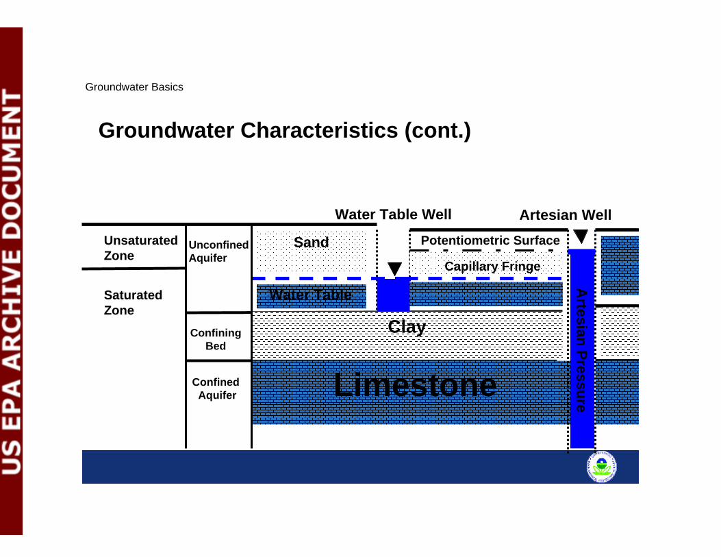
Saturated Zone
Unconfined Aquifer
Water Table Well
Potentiometric SurfaceUnsaturated Zone
Limestone
Artesian Pressure
Confining Bed
Confined Aquifer
Clay
Sand
Artesian Well
Water Table
Capillary Fringe
Groundwater Basics

Calculating direction of groundwater flow direction and hydraulic gradient1. Need a minimum of three wells 2. Need horizontal distance between wells3. Identify well with intermediate water level (MW-2 26.20m below ground surface [bgs])4. Determine where 26.20 m (bgs) is on the line between MW 1 and MW 35. Perpendicular line to the dashed line is flow direction6. Hydraulic gradient is calculated using the change in head over change in horizontal distance Drinking Water
WellFacility Boundary
MW-126.07
MW-326.26 m
MW-226.20
6
26.20Groundwater flow direction
26.1526.10
Groundwater Characteristics (cont.)
Groundwater Basics
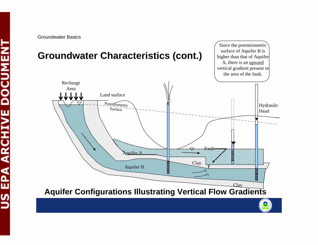
Recharge Area
Aquifer A
Aquifer B
Clay
Clay
Land surface
Potentiometric Surface
Fault
Aquifer Configurations Illustrating Vertical Flow Gradients
Since the potentiometric surface of Aquifer B is
higher than that of Aquifer A, there is an upward
vertical gradient present in the area of the fault.
Hydraulic Head
Groundwater Characteristics (cont.)
Groundwater Basics
Groundwater Flow Rate – Dependent on hydraulic conductivity (K) and hydraulic
gradients
Hydraulic Conductivity (K)– Rate in distance over time (M/Sec) at which water moves
through a permeable medium– Can be measured using aquifer tests or can use literature
values– More porous the medium the higher the conductivity
• Gravel and sand have high conductivity; clays and shale have lower conductivity
Groundwater Characteristics (cont.)
Groundwater Basics

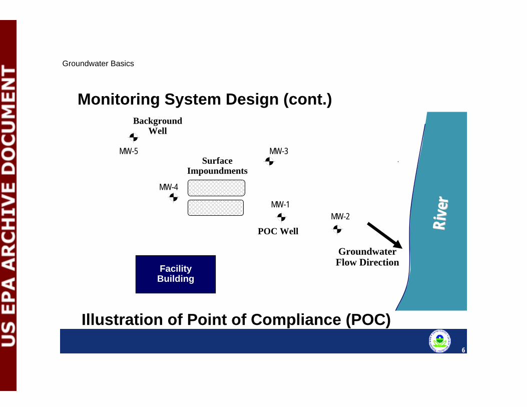
Monitoring System Design
Considerations for Well Design and Location– Sufficient wells properly located to yield both background
groundwater quality and water quality passing the point of compliance
– Location of point of compliance well(s) – Background groundwater quality– Ability to determine groundwater flow direction– Consider vertical and horizontal gradients– Contaminants being monitored such as DNAPL and LNAPL
Groundwater Basics
Rive
rRi
ver
Illustration of Point of Compliance (POC)
Groundwater Flow Direction
Drinking Water Well
FacilityBuilding
Background Well
Facility Boundary
Surface Impoundments
MW-1
MW-5 MW-3
MW-4
MW-2
6
POC Well
Monitoring System Design (cont.)
Groundwater Basics
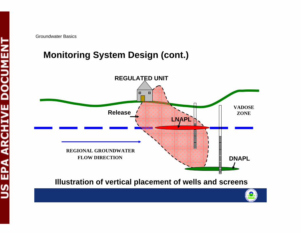
REGIONAL GROUNDWATERFLOW DIRECTION
VADOSEZONE
REGULATED UNIT
LNAPL
DNAPL
Illustration of vertical placement of wells and screens
Monitoring System Design (cont.)
Groundwater Basics
Release
Monitoring System Construction
Considerations for Well Construction– Installation methods and type of wells– Integrity of casing– Screening and gravel pack– Annular seal
Groundwater Basics
Monitoring System Construction
Well Installation Methods – Hollow-Stem Augers– Mud Rotary– Air Rotary– Reverse Circulation– Rotasonic– Direct Push/Hydro Punch
Groundwater Basics
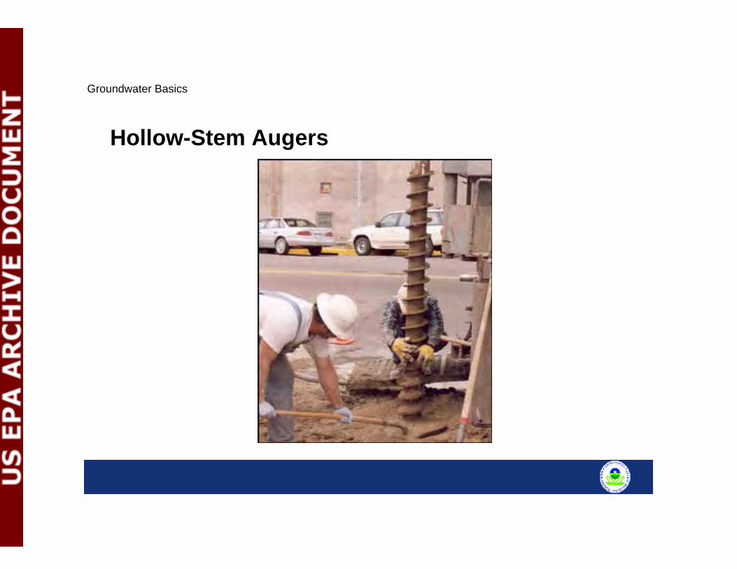
Hollow-Stem Augers
Groundwater Basics

Mud Rotary
Groundwater Basics
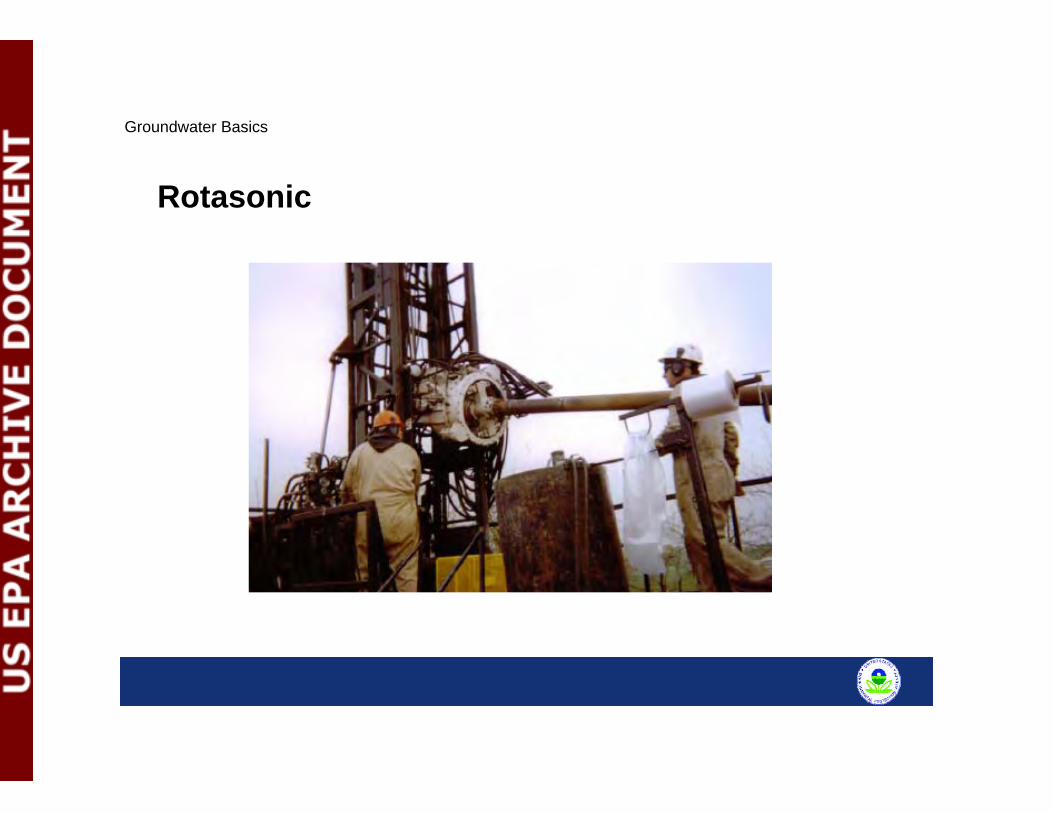
Rotasonic
Groundwater Basics
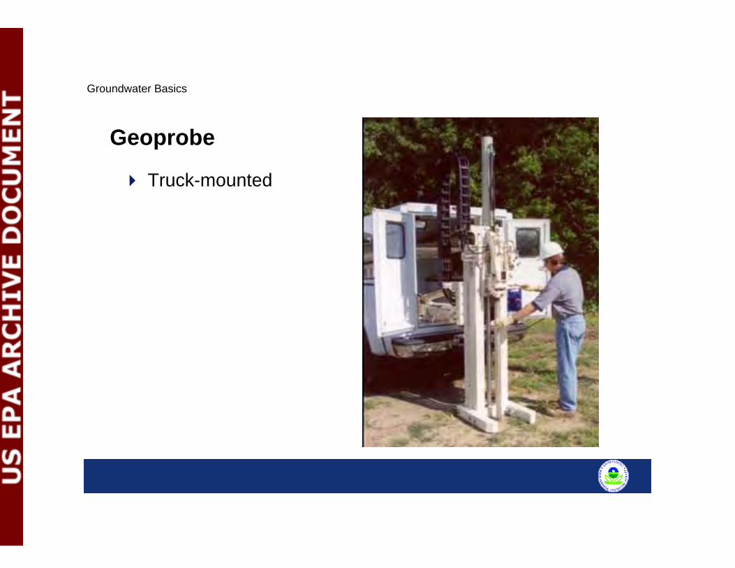
Geoprobe
Truck-mounted
Groundwater Basics
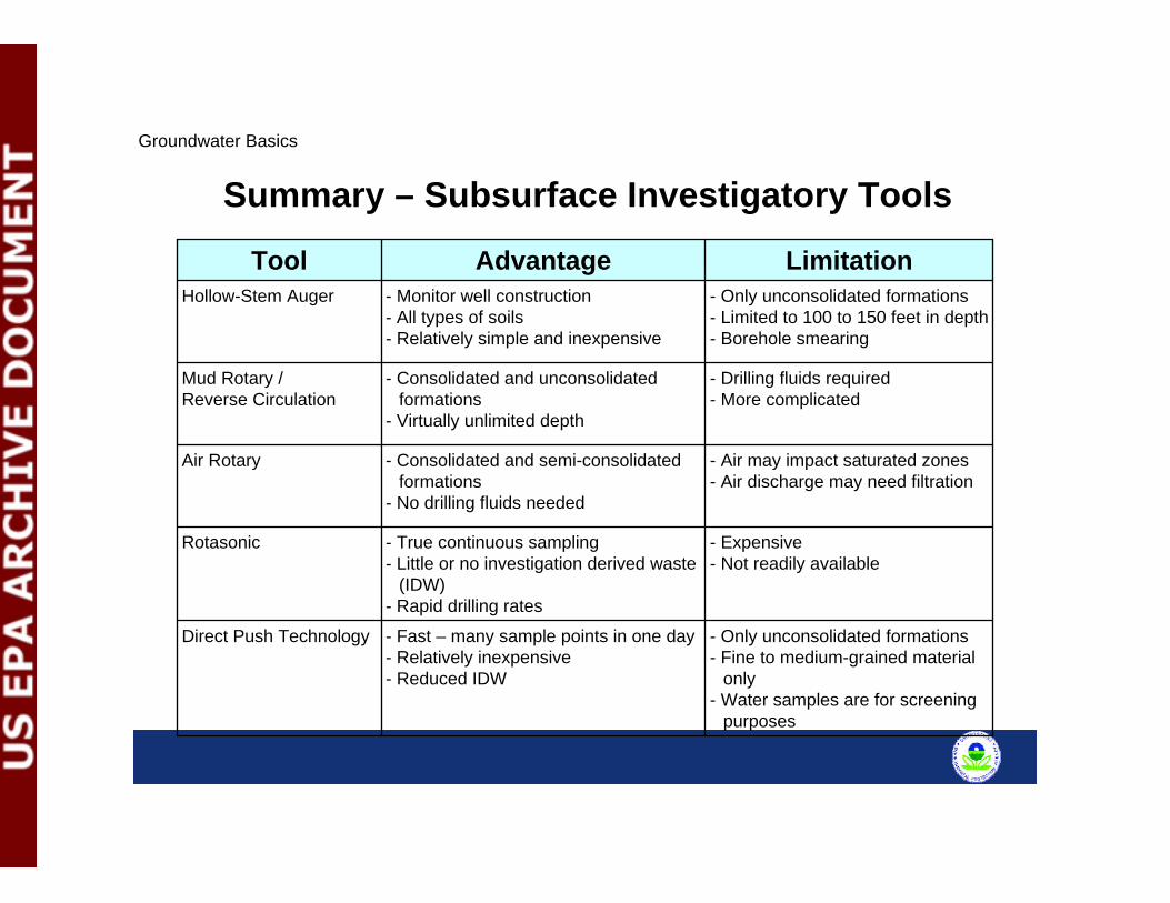
Summary – Subsurface Investigatory Tools
- Only unconsolidated formations- Fine to medium-grained material
only- Water samples are for screening
purposes
- Fast – many sample points in one day- Relatively inexpensive- Reduced IDW
Direct Push Technology
- Expensive- Not readily available
- True continuous sampling- Little or no investigation derived waste
(IDW)- Rapid drilling rates
Rotasonic
- Air may impact saturated zones- Air discharge may need filtration
- Consolidated and semi-consolidated formations
- No drilling fluids needed
Air Rotary
- Drilling fluids required- More complicated
- Consolidated and unconsolidated formations
- Virtually unlimited depth
Mud Rotary / Reverse Circulation
- Only unconsolidated formations- Limited to 100 to 150 feet in depth- Borehole smearing
- Monitor well construction- All types of soils- Relatively simple and inexpensive
Hollow-Stem Auger
LimitationAdvantageTool
Groundwater Basics
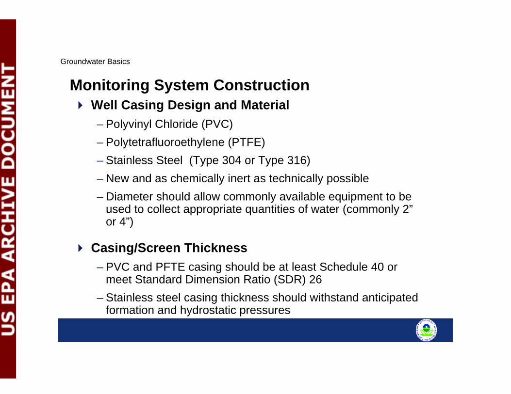
Monitoring System ConstructionWell Casing Design and Material– Polyvinyl Chloride (PVC)– Polytetrafluoroethylene (PTFE)– Stainless Steel (Type 304 or Type 316)– New and as chemically inert as technically possible– Diameter should allow commonly available equipment to be
used to collect appropriate quantities of water (commonly 2”or 4”)
Casing/Screen Thickness– PVC and PFTE casing should be at least Schedule 40 or
meet Standard Dimension Ratio (SDR) 26– Stainless steel casing thickness should withstand anticipated
formation and hydrostatic pressures
Groundwater Basics

Types of Well Screens– Only commercially fabricated– Factory slotted – Continuous-slot – Wire-wound
Select appropriate slot size - based on grain size data – Silt use 10 slot (0.010 inch slots)– Sand and gravel use 20 slot (0.020 inch slots)
Screen length (TEGD recommends 5 to 10 feet)
Silt trap/sump required (not to exceed two feet in length)
Placed at the aquifer of interest
Groundwater Basics
Monitoring System Construction (cont.)
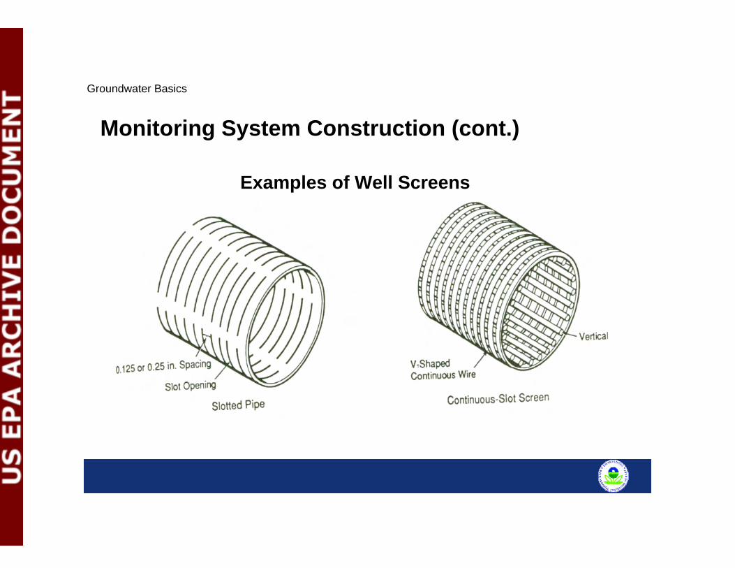
Examples of Well Screens
Groundwater Basics
Monitoring System Construction (cont.)
Filter Pack Composition– Washed and contaminant free– 95%+ siliceous material (quartz)– Water-soluble material not to exceed 1%– Inert
Filter Pack Construction– Should extend from the base of the sump to a minimum of
two feet above the screen– “Sugar” sand (fine sand) may be placed above the filter pack– Use tremie pipe to place the filter pack material
Groundwater Basics
Monitoring System Construction (cont.)
Bentonite Seal– Protect monitored zone against surface infiltration of
contaminants and cross contamination between permeable zones
– Required to be two feet in thickness – Allow a minimum of eight hours to hydrate before grouting
Annular seal materials– Cement-bentonite grout—Portland cement, bentonite, and
potable water – High solids bentonite—designed for grouting
Groundwater Basics
Monitoring System Construction (cont.)

Grout– Mechanical mixing of grout is recommended– Grout weight should be verified and recorded within + or –
0.2 pounds per gallon of the desired/appropriate weight– Grout should be placed using a rigid, side discharge tremie
pipe and grout pump from the top of the bentonite seal to the ground surface
Types of Surface Completions– Above-ground– Flush mount
Groundwater Basics
Monitoring System Construction (cont.)
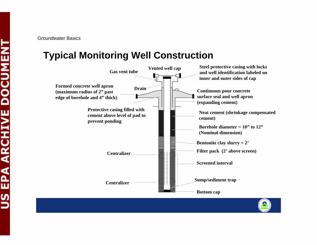
Typical Monitoring Well ConstructionSteel protective casing with locks and well identification labeled on inner and outer sides of cap
Formed concrete well apron (maximum radius of 2” past edge of borehole and 4” thick)
Continuous pour concrete surface seal and well apron (expanding cement)
Neat cement (shrinkage compensated cement)
Borehole diameter = 10” to 12”(Nominal dimension)
Bentonite clay slurry = 2’
Filter pack (2’ above screen)
Screened interval
Centralizer Sump/sediment trap
Vented well capGas vent tube
Protective casing filled with cement above level of pad to prevent ponding
Centralizer
Drain
Bottom cap
Groundwater Basics
Sampling and Analysis
Considerations for sample collection and analysis– Equipment decontamination– Static water level measurements– Well purging/sample withdrawal– Quality assurance samples– Preservation, shipment and chain of custody
Groundwater Basics
Sampling and Analysis (cont.)Equipment Decontamination Goal – Eliminate cross contamination of samples
Required Steps– Physical removal– Detergent wash – lab grade, non-phosphate (e.g., Alconox)– Tap water rinse– Deionized water rinse– Air dry
Optional Steps– 10% nitric acid rinse– Solvent rinse – pesticide grade (e.g., hexane)
Groundwater Basics
Static Water Level Measurements Measure prior to purging– To 0.01-foot increment– Reference vertical datum (e.g., above mean sea level)– Measure inner casing– Steel tape/sounding device– Immiscible layers (i.e., LNAPLs)
Groundwater Basics
Sampling and Analysis (cont.)
Well Purging/Sample Withdrawal– Bailers– Low-Flow Pump– Hydrasleeve– Peristaltic Pump– Bladder Pump– Diffusion bag
Groundwater Basics
Sampling and Analysis (cont.)
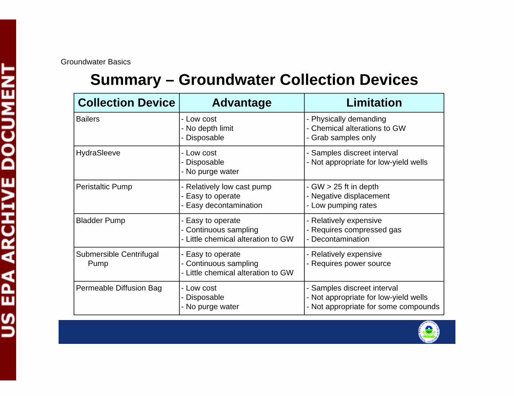
Summary – Groundwater Collection Devices
- Samples discreet interval- Not appropriate for low-yield wells- Not appropriate for some compounds
- Low cost- Disposable- No purge water
Permeable Diffusion Bag
- Relatively expensive- Requires power source
- Easy to operate- Continuous sampling- Little chemical alteration to GW
Submersible Centrifugal Pump
- Relatively expensive- Requires compressed gas- Decontamination
- Easy to operate- Continuous sampling- Little chemical alteration to GW
Bladder Pump
- GW > 25 ft in depth- Negative displacement- Low pumping rates
- Relatively low cast pump- Easy to operate- Easy decontamination
Peristaltic Pump
- Samples discreet interval- Not appropriate for low-yield wells
- Low cost- Disposable- No purge water
HydraSleeve
- Physically demanding- Chemical alterations to GW- Grab samples only
- Low cost- No depth limit- Disposable
Bailers
LimitationAdvantageCollection Device
Groundwater Basics
Sampling and AnalysisSample order– Volatiles– Semi-volatiles– Metals
Preservatives– Typical – Acid, Refrigeration < 4°C– Method-specific
Groundwater Basics
Sampling and Analysis (cont.)Sample Collection - QA/QC Requirements– Trip blank– Equipment blank/rinsate– Field Duplicates– Field/Ambient Blank– Matrix Spike/Duplicates
Groundwater Basics
Analytical Method Selection should consider– Site history (e.g., landfill, refueling station, or vehicle
maintenance)– Historical analytical data for site soils and groundwater (e.g.,
data from PA/SI or RI/FS)– Historical analytical data from upgradient sites that may
impact groundwater quality– Regulatory criteria applicable to groundwater monitoring at
the site– Background contaminants
Groundwater Basics
Sampling and Analysis (cont.)
Documentation– Chain-of-custody– Sample labels/tags– Custody seals– Field logbook
Groundwater Basics
Sampling and Analysis (cont.)