Embed Size (px)
DESCRIPTION
Session 7 Special test Cryo-optical test of the PLANCK reflectors Author(s): S. Roose, A. Cucchiaro (Centre Spatial de Liège) Speaker: Stéphane Roose (e-mail :[email protected]). Torino 20/21/22 March 2006. 1.Project Historical Background 2.Overall Description 3.Test results - PowerPoint PPT Presentation
Citation preview
2nd International Workshop onVerification and Testing of Space Systems
Session 7Special testSpecial test
Cryo-optical test of the PLANCK reflectors
Author(s): S. Roose, A. Cucchiaro(Centre Spatial de Liège)
Speaker: Stéphane Roose (e-mail :[email protected])
Torino 20/21/22 March 2006
Speaker: S. Roose (CSL) Torino 20/21/22 March 2006 2
2nd International Workshop onVerification and Testing of Space Systems
Summary
• 1.Project Historical Background• 2.Overall Description• 3.Test results• 4.Lessons learned
Speaker: S. Roose (CSL) Torino 20/21/22 March 2006 3
2nd International Workshop onVerification and Testing of Space Systems
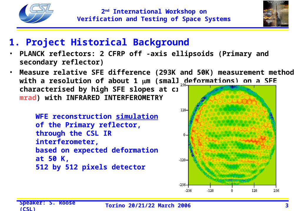
1. Project Historical Background• PLANCK reflectors: 2 CFRP off -axis ellipsoids (Primary and secondary reflector)
• Measure relative SFE difference (293K and 50K) measurement method with a resolution of about 1 m (small deformations) on a SFE characterised by high SFE slopes at cryo-genic temperature (1 mrad) with INFRARED INTERFEROMETRY
WFE reconstruction simulation of the Primary reflector, through the CSL IR interferometer, based on expected deformation at 50 K,512 by 512 pixels detector

Speaker: S. Roose (CSL) Torino 20/21/22 March 2006 4
2nd International Workshop onVerification and Testing of Space Systems
2.1. Overall Description: Secondary reflector (Single pass interferometer)
OM2
OM2C
F
Thermal shroud
Reflector support
Illumination optics
Interferometer cavity bench
Planck SR
Collecting optics
Optical bench
Vacuum flange with ZnSe windows
Speaker: S. Roose (CSL) Torino 20/21/22 March 2006 5
2nd International Workshop onVerification and Testing of Space Systems
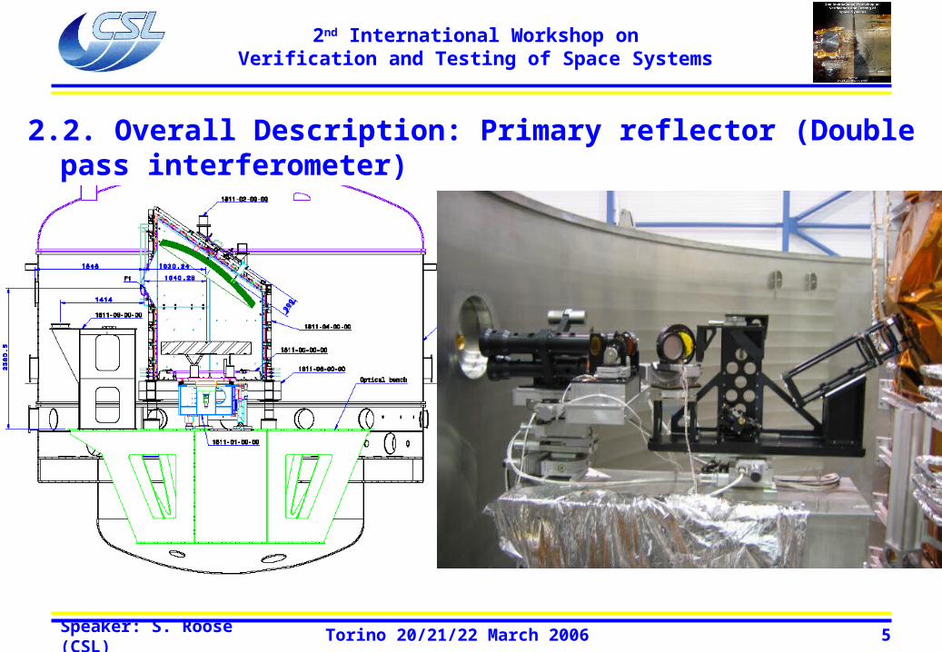
2.2. Overall Description: Primary reflector (Double pass interferometer)

Speaker: S. Roose (CSL) Torino 20/21/22 March 2006 6
2nd International Workshop onVerification and Testing of Space Systems

Speaker: S. Roose (CSL) Torino 20/21/22 March 2006 7
2nd International Workshop onVerification and Testing of Space Systems
3.1. Test results Secondary reflector QM: Full aperture test
Reflector not measurable in CRYO with this set-up: fringe density (slopes) too high! How Much?
Interferogram: 293 K Interferogram: 50 K WFE: 50 K
Speaker: S. Roose (CSL) Torino 20/21/22 March 2006 8
2nd International Workshop onVerification and Testing of Space Systems
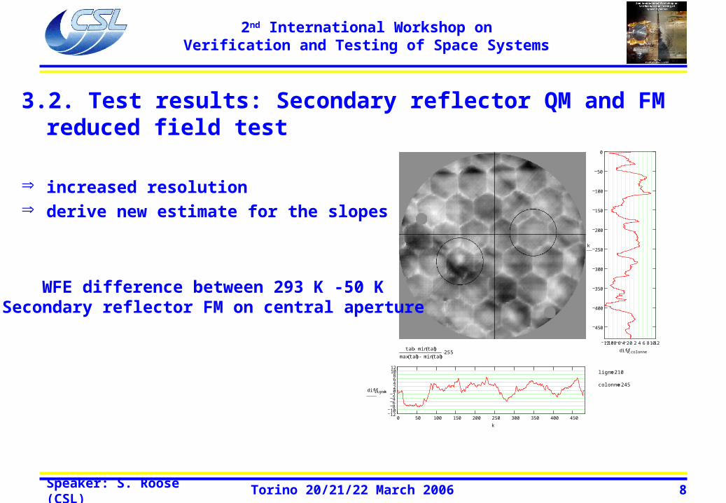
3.2. Test results: Secondary reflector QM and FM reduced field test
increased resolution derive new estimate for the slopes = 2 mrad
PLANCK SECONDARY MIRROR - FLIGHT MODEL - REDUCED PUPIL TEST - FM 1
name_ref "SRFM_1_1_293K_08DEC04_ZOOM1x_MOYENNE_REM9_corrige facteur 2.TXT"
name "SRFM_1_1_50K_17DEC04_ZOOM1x_MOYENNE_REM9_corrige facteur 2.TXT"
eti diff( ) 5.023 max diff( ) 15.01 min diff( ) 18.864 µm WFE
di 2 dj 1
1210 8 6 4 2 0 2 4 6 8 1012
450
400
350
300
250
200
150
100
50
0
k
diff k colonnetab min tab( )
max tab( ) min tab( )255
0 50 100 150 200 250 300 350 400 4501210
864202468
1012
diff ligne k
k
ligne 210
colonne 245
WFE difference between 293 K -50 KSecondary reflector FM on central aperture
Speaker: S. Roose (CSL) Torino 20/21/22 March 2006 9
2nd International Workshop onVerification and Testing of Space Systems
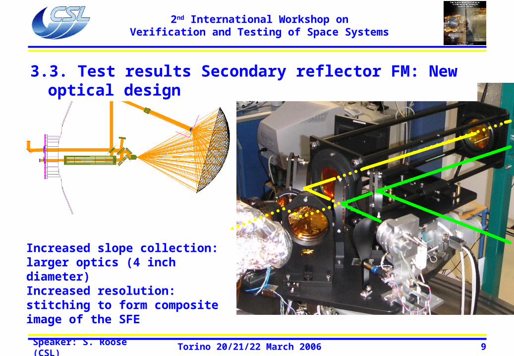
• Test results Secondary Reflector FM: New optical design
Increased slope collection: larger optics (4 inch diameter)Increased resolution: stitching to form composite image of the SFE
3.3. Test results Secondary reflector FM: New optical design
Speaker: S. Roose (CSL) Torino 20/21/22 March 2006 10
2nd International Workshop onVerification and Testing of Space Systems
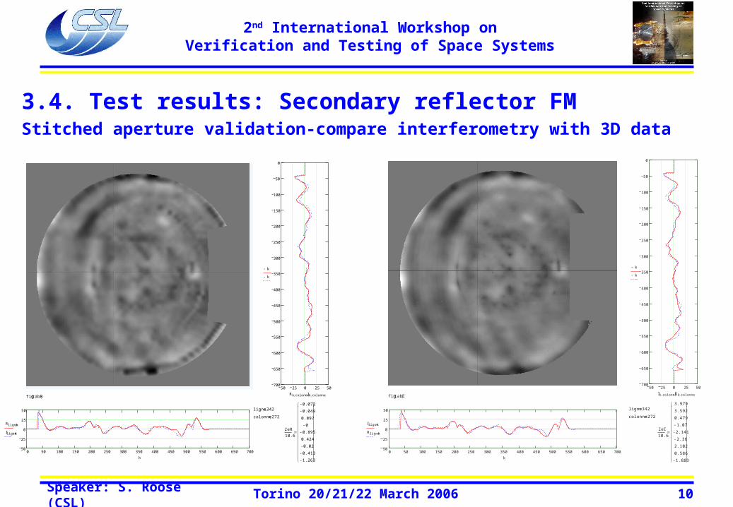
3.4. Test results: Secondary reflector FM Stitched aperture validation-compare interferometry with 3D data
PLANCK SECONDARY MIRROR - FLIGHT MODEL
ASED measurements projected through all optical system
eti R( ) 10.261 max R( ) 62.536 min R( ) 53.934 µm WFE
50 25 0 25 50700
650
600
550
500
450
400
350
300
250
200
150
100
50
0
k
k
Rk colonne Ik colonnefig tabR( )
0 50 100 150 200 250 300 350 400 450 500 550 600 650 70050
25
0
25
50
Rligne k
Iligne k
k
ligne 342
colonne 272
ZeR
10.6
0.072
0.049
0.097
0
0.895
0.424
0.02
0.413
1.263
PLANCK SECONDARY MIRROR - FLIGHT MODEL - test 2
name "SRFM_2_1_295K_26JUN05_3STIT.mca"
eti I( ) 10.788 max I( ) 82.439 min I( ) 47.24 µm WFE
50 25 0 25 50700
650
600
550
500
450
400
350
300
250
200
150
100
50
0
k
k
Ik colonne Rk colonnefig tabI( )
0 50 100 150 200 250 300 350 400 450 500 550 600 650 70050
25
0
25
50
Iligne k
Rligne k
k
ligne 342
colonne 272
ZeI
10.6
3.979
3.592
0.479
1.07
2.141
2.36
2.102
0.586
1.883
Speaker: S. Roose (CSL) Torino 20/21/22 March 2006 11
2nd International Workshop onVerification and Testing of Space Systems
dj2 146
di2 411
dj1 429
di1 164
colonne 272
ligne 342
0 50 100 150 200 250 300 350 400 450 500 550 600 650 70030
15
0
15
30
Dligne k
k
fig tab( )
30 15 0 15 30700
650
600
550
500
450
400
350
300
250
200
150
100
50
0
k
D k colonne
µm WFEmin D( ) 59.909max D( ) 50.322eti D( ) 8.472
name_ref name
name "SRFM_2_1_50K_30JUN05_1STIT.mca"
name_ref "SRFM_2_1_295K_26JUN05_3STIT.mca"
PLANCK SECONDARY MIRROR - FLIGHT MODEL - test 2 PLANCK SECONDARY MIRROR - FLIGHT MODEL - test 2 - data integrity at 50K
name_ref "SRFM_2_1_50K_30JUN05_1STIT.mca"
name "SRFM_2_1_50K_30JUN05_2STIT.mca"
name_ref name
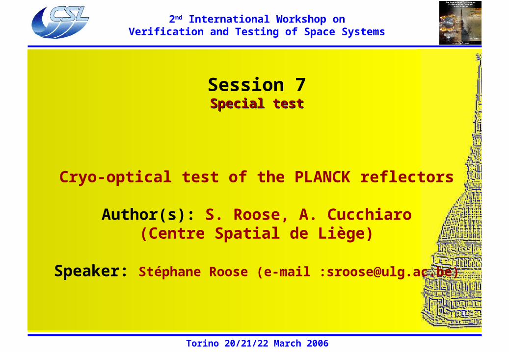
eti D( ) 0.17 max D( ) 2.972 min D( ) 3.108 waves WFE
2 1 0 1 2700
650
600
550
500
450
400
350
300
250
200
150
100
50
0
k
Dk colonnefig D0( )
0 50 100 150 200 250 300 350 400 450 500 550 600 650 7002
1
0
1
2
Dligne k
k
ligne 338
colonne 97
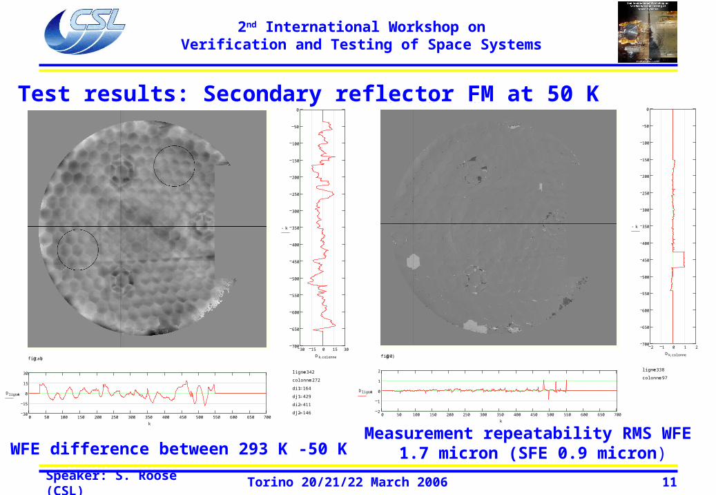
WFE difference between 293 K -50 KMeasurement repeatability RMS WFE
1.7 micron (SFE 0.9 micron)
3.5. Test results: Secondary reflector FM at 50 K
Speaker: S. Roose (CSL) Torino 20/21/22 March 2006 12
2nd International Workshop onVerification and Testing of Space Systems
fig sphe( )
max sphe( ) 6.871
min sphe( ) 4.738
moy sphe( ) 0
et sphe( ) 0.477
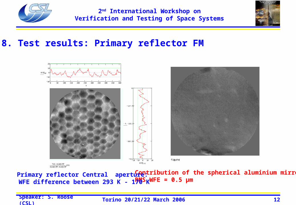
Contribution of the spherical aluminium mirror RMS WFE = 0.5 μm
col 195column
lig 220line
limit 20limit for the plot =/- µm
stdev_diff 5.552standard deviation of DBL PATH WFE in µm
mi_diff 20.355minimum of DBL PATH WFE in µm
ma_diff 20.077maximum of DBL PATH WFE in µm
Tdi min diff( )max diff( ) min diff( )
255
20 10 0 10 20511
383.25
255.5
127.75
0
k
diff k col
0 50 100 150 200 250 300 350 400 450 50020
10
0
10
20
diff lig k
k
name_r "PRFM_1_1_298K_2MAY05_ZOOM2x_01"
name "PRFM_1_2_170K_8MAY05_ZOOM2x_pup1_OPD_1"
DIFFERENCE : NAME - NAME_R
PLANCK PRIMARY REFLECTOR FLIGHT MODEL PUPIL 1
Primary reflector Central aperture: WFE difference between 293 K - 170 K
3.8. Test results: Primary reflector FM
Speaker: S. Roose (CSL) Torino 20/21/22 March 2006 13
2nd International Workshop onVerification and Testing of Space Systems
col 604column
lig 695line
limit 50limit for the plot =/- µm
stdev_diff 8.162standard deviation of DBL PATH WFE in µm
mi_diff 48.51minimum of DBL PATH WFE in µm
ma_diff 45.396maximum of DBL PATH WFE in µm
Tdi min diff( )max diff( ) min diff( )
255
30 15 0 15 301300
1200
1100
1000
900
800
700
600
500
400
300
200
100
0
k
diff k col
0 100 200 300 400 500 600 700 800 900 1000 1100 1200 130030
15
0
15
30
difflig k
k
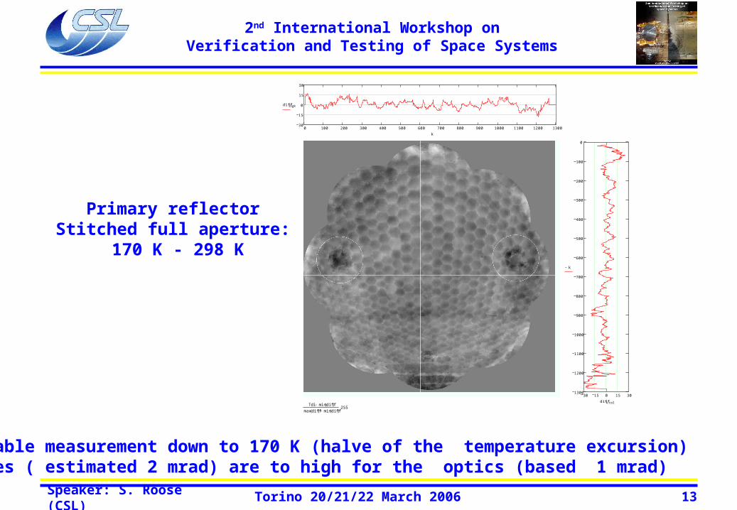
name_r "Coma175\PRFM_1_1_298K_2MAY05_ZOOM2x_3STIT"
name "Coma175\PRFM_1_1_170K_11MAY05_ZOOM2x_1STIT"
DIFFERENCE : NAME - NAME_R
PLANCK PRIMARY REFLECTOR FLIGHT MODEL FULL PUPIL - STITCHING
Primary reflector Stitched full aperture:
170 K - 298 K
Reliable measurement down to 170 K (halve of the temperature excursion) Slopes ( estimated 2 mrad) are to high for the optics (based 1 mrad)
Speaker: S. Roose (CSL) Torino 20/21/22 March 2006 14
2nd International Workshop onVerification and Testing of Space Systems
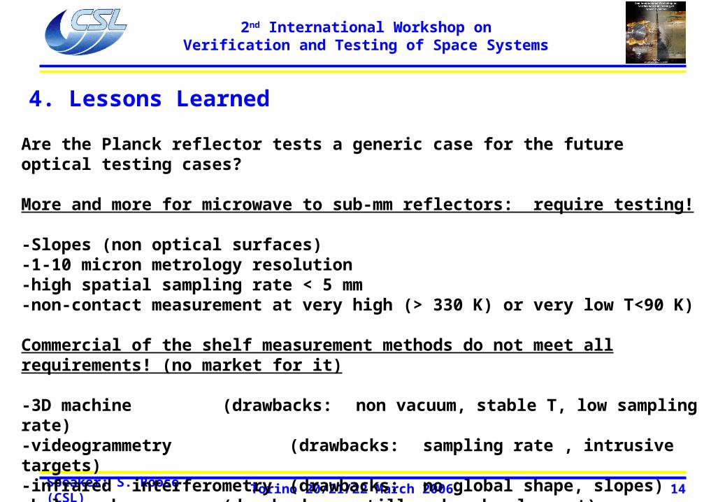
4. Lessons Learned
Are the Planck reflector tests a generic case for the future optical testing cases?
More and more for microwave to sub-mm reflectors: require testing!
-Slopes (non optical surfaces)-1-10 micron metrology resolution-high spatial sampling rate < 5 mm-non-contact measurement at very high (> 330 K) or very low T<90 K)
Commercial of the shelf measurement methods do not meet all requirements! (no market for it)
-3D machine (drawbacks: non vacuum, stable T, low sampling rate)-videogrammetry (drawbacks: sampling rate , intrusive targets)-infrared interferometry (drawbacks: no global shape, slopes)-holography (drawbacks: still under development)-lasertracker (drawbacks: non vacuum, contact)
Speaker: S. Roose (CSL) Torino 20/21/22 March 2006 15
2nd International Workshop onVerification and Testing of Space Systems
Reflector development needs to consider testing problem very early in the project!
Why?
-thermal-elastic models do not tell the absolute truth: over-sizing the metrology tool might be necessary (increase test complexity). (PLANCK reflectors: wrong starting hypotheses in the assessment of commercial IR interferometry feasibility)
-allow to iterate with small scale test and metrology which addresses the hard-points. (PLANCK reflectors reduced field test)
-accept the non-universality of a method: divide and conquer, develop several simple test(PLANCK reflectors: SFE with interferometry (CSL) and global shape with videogrammetry (AAS-Cannes))
-early adaptation of method to the thermal vacuum test to allow technology developments. (Planck reflectors: Videogrammetry targets at low temperature (ESTEC), High resolution IR interferometer, Holography (CSL))