Embed Size (px)
Citation preview
SET-BASED DESIGN SPACE EXPLORATION ENABLED BYDYNAMIC CONSTRAINT ANALYSIS
Justin R. Kizer,∗ Dimitri N. Mavris∗∗Aerospace Systems Design Laboratory, Georgia Institute of Technology, Atlanta, GA 30332 USA
Keywords: aircraft and systems integration, design space exploration, constraint analysis, set-baseddesign, conceptual design
Abstract
The complexity and variability of requirementsmake physics-based conceptual design of modernaircraft computationally expensive. To addressthis issue, a set-based methodology for efficientdesign space exploration is proposed. Enabledby a parametric, energy-based, constraint sensi-tivity analysis and convex hull techniques, thismethodology was tested on a case study whichsampled and mapped the feasible design spacefor a notional Large Twin Aisle passenger air-craft. Use of the methodology ultimately allowedfor the identification of a robust feasible designspace and within it a flexible family of solutions.
Nomenclature
PS specific excess power [ft/s]T thrust [lbs]D drag [lbs]R takeoff configuration excess drag [lbs]V velocity [ft/s ]W weight [lbs]m mass [lbm (slugs)]dV/dt acceleration [ft/s2]SL sea-levelg0 acceleration due to gravity at SL [ft/s2]h altitude [ft]q dynamic pressure [lbs/ f t2]Sre f reference wing area [ f t2]K1,K2 parabolic drag polar coefficientsCD0 zero-lift drag coefficientCL aircraft lift coefficientn load factor
TSL SL static thrust [lbs]WTO takeoff gross weight (TOGW) [lbs]α thrust lapseβ weight fraction (W/WTO)TSL/WTO thrust to weight ratioWTO/Sre f wing loading [lbs/ f t2]
1 Introduction
One of the primary objectives of the conceptualdesign of aircraft systems is to depict the de-sign space and highlight possible trades for theplanned vehicle [1]. In order to accomplish thistask, it is paramount that the full set of systemrequirements be characterized and incorporatedas rapidly as possible into the design process.However, complications arise due to the inherentvariability of many requirements. This variabil-ity can be a product of factors such as: customerpreferences, competitor actions, new regulations,volatility in fuel prices, cost overruns and sched-ule slippages. Combining these factors with thetypical time-scale of large aircraft developmentprograms often results in a final system that isnoticeably different from what was originally en-visioned [2]. Therefore, to avoid performancedegradation and costly re-design, it is extremelyimportant for any design program to maintainsome degree of design freedom throughout thedesign process. To illustrate, one can think ofnavigating via a printed map with a pre-plannedroute contrasted with using a portable GPS. Bothoptions can provide the nominal route to reachthe destination, with the map being less costly
1

JUSTIN R. KIZER, DIMITRI N. MAVRIS
and likely more concise than the GPS. However,with the GPS, should the driver encounter trafficon the nominal path, they possess the knowledgeand freedom to intelligently re-route to a fasteroption. Furthermore, the map, akin to an opti-mized point design, is valid for a single objec-tive function. Should the driver prefer to avoidhighways or save fuel, then the pre-planned mapdirections may no longer provide the optimumroute.
The objective of this study was to developa methodology to efficiently provide a dynamicmap for the feasible design space (FDS). Rec-ognizing that requirements, constraints and ob-jectives evolve over time, this map must providea robust family of solutions that remain feasi-ble throughout the design process. To constructthis methodology, Set-Based Design (SBD) tech-niques were employed to map and then dividethe larger design space into a series of con-straint dependent feasible sets from which theFDS could be determined. To enable this ex-ploration and mapping however, it was neces-sary to have an environment in which constraintsand requirements could not only be rapidly eval-uated, but also perturbed at will. Thus a paramet-ric, conceptual-level physics-based, aircraft siz-ing and synthesis tool was developed to providethe transparency and flexibility to design a vehi-cle subject to varying constraints. An energy-based constraint analysis was utilized to supplythe constraints and when coupled with the de-sign tool, formed an ideal test bed for the pro-posed methodology. Using appropriate Designof Experiments (DOE), the design space for aLarge Twin Aisle (LTA) passenger transport air-craft was explored and then the FDS discoveredand mapped using adapted SBD techniques. Fi-nally, subjecting this mapping to varying require-ments and constraints allowed the identificationof a robust set of possible aircraft designs.
This formulation, while applicable to a largevariety of engineering design problems, is pri-marily motivated by the projected growth of thecivil air transportation fleet and established en-vironmental goals for the future of commercialaviation [3, 4, 5]. These objectives, which seekreductions in fuel burn, noise and combustion
product emissions, will likely serve as driving re-quirements for the development of future civiltransport aircraft. Though variable in natureand subject to developing regulations, translationof these requirements into constraints and ob-jectives is crucial in understanding the possibleshape of the design space and desirability of fu-ture aircraft systems.
2 The Feasible Design Space
Before any design decisions can be made or pref-erences considered, the designer must determinethe set of what is possible, that is, the FDS.Knowing such information will enable trades tobe performed between feasible designs and pro-vide flexibility should a preferred design becomenon-optimal. To characterize and describe theFDS, a mapping is desired that will depict notsimply a collection of feasible design points, butthe entire feasible region as defined by all the sys-tem requirements and constraints.
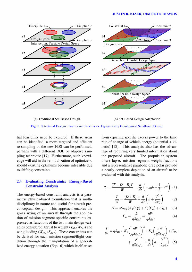
2.1 Mapping the Design Space: Set-BasedDesign
Set-Based Design (SBD) or Set-Based Concur-rent Engineering is a design methodology whichpresents an alternative to traditional "point basedconcurrent engineering" [6, 7, 8]. Instead oflocking in a large number of design decisionsearly on in the design process to move forwardwith an ’optimal’ point-design, the methodol-ogy seeks to simultaneously increase knowledgeabout the design space and relevant requirementswhile maintaining as much design freedom aspossible [9, 10]. Traditional SBD as depictedin Fig. 1a, emphasizes mapping of the designspace through the determination of feasible re-gions (sets) which arise from preferences in de-sign variable values and analyses performed in-dependently and in parallel by different disci-plines [11, 12]. Because of their isolated na-ture and discipline driven preferences, these in-dependently developed design spaces may be dis-joint [13]. SBD then "integrates through intersec-tion" to find a global feasible set with the objec-tive to consider all constraints and "seek concep-
2
Set-Based Constraint Analysis
tual robustness" [11]. While this approach typ-ically requires a much more resource intensiveand lengthy conceptual design phase, it has beenshown to mitigate costs and program delays asso-ciated with design problems encountered in de-tailed design or production. By carrying forwardmultiple design solutions further into the designprocess, SBD provides feasible alternatives whenunforeseen problems render the nominal designinfeasible or drastically degrade its performance[7].
Establishing the FDS is crucial in conceptualdesign, but it is entirely dependent on the re-quirements and constraints that determine whichdesigns are feasible. Traditional SBD oftenoperates on a static set of constraints, there-fore, this investigation utilizes an adaptation ofSBD that recognizes that these requirements andconstraints can change over time. Designatedas Dynamically Constrained Set-Based-Design(DynamiC-SBD), this implementation is there-fore more focused on how the nominal FDS isrefined through the consideration of varying con-straints and intelligent re-exploration using theinformation contained within the individual con-straint defined feasible sets. Through the con-nection with the sizing and synthesis tool andthe energy-based constraint analysis, the differ-ent disciplines relevant in pre-conceptual designare already inherently integrated. What remainsis the use of SBD principles to refine the FDS to"seek conceptual robustness" and produce a flex-ible family of solutions insensitive to moderatevariability in constraints.
Similar to traditional SDB, DynamiC-SBD(Fig. 1b) begins with the establishment of thenominal feasible space. This is accomplishedby performing an initial design space explorationwith which individual constraint defined feasiblesets are determined. The intersection of theseconstraint defined feasible sets then forms an ap-proximation for the notional FDS. These con-straints are then perturbed and the space intel-ligently re-sampled (targeted near areas of per-turbation of active segments of the constraints).This re-sampling coupled with the initial sampleset allows for the rebounding of the constraint de-fined feasible sets and ultimately the determina-
tion of the FDS that results from the perturbedconstraints. By appropriately perturbing con-straints this methodology ultimately allows forthe estimation of a robust FDS.
2.2 Querying the Design Space: Physics-Based Computational Modelling
As the analysis of an aircraft system is both mul-tidisciplinary and highly combinatorial, the de-termination of this feasible space is often a re-source intensive task. As physical testing is in-feasible at this stage of design due to the sheernumber of design alternatives to be considered,physics based computational modelling is oftenemployed. In order to explore the design spacethoroughly and accommodate variable require-ments and objective functions, it is desired thatthe computational models employed be paramet-ric in nature. A parametric model enables rapidand semi-autonomous design space exploration,however, even with the use of such a model, thereis a limit to what can be examined in search of theFDS.
2.3 Exploring the Design Space: Design ofExperiments
To optimize the return of a limited experimen-tal budget, DOE have often been employed toefficiently extract information from large com-binatorial spaces [14]. Many types of DOE ex-ist, ranging from traditional full and fractionalfactorial orthogonal designs to structured spacefilling designs to Pseudo-Monte Carlo Sampling[15, 16]. Some designs are intended to better cap-ture behavior of the problem near the extremesof the design space, others closer to the interior.For an initial sampling and determination of thenominal feasible space, the designer should em-ploy the DOE or combination of DOE designswhich they believe to best suit the problem. How-ever, to analyze the effects of variable require-ments it is undesirable to require the re-samplingof the entire design space every time a constraintis perturbed. To avoid the unnecessary compu-tational effort expended in retreading infeasibleground, there is a need to intelligently map thedesign space such that only new areas of poten-
3
JUSTIN R. KIZER, DIMITRI N. MAVRIS
(a) Traditional Set-Based Design (b) Set-Based Design Adaptation
Fig. 1 Set-Based Design: Traditional Process vs. Dynamically Constrained Set-Based Design
tial feasibility need be explored. If these areascan be identified, a more targeted and efficientre-sampling of the new FDS can be performed,perhaps with a different DOE or adaptive sam-pling technique [17]. Furthermore, such knowl-edge will aid in the reinitialization of optimizers,should existing optimums become infeasible dueto shifting constraints.
2.4 Evaluating Constraints: Energy-BasedConstraint Analysis
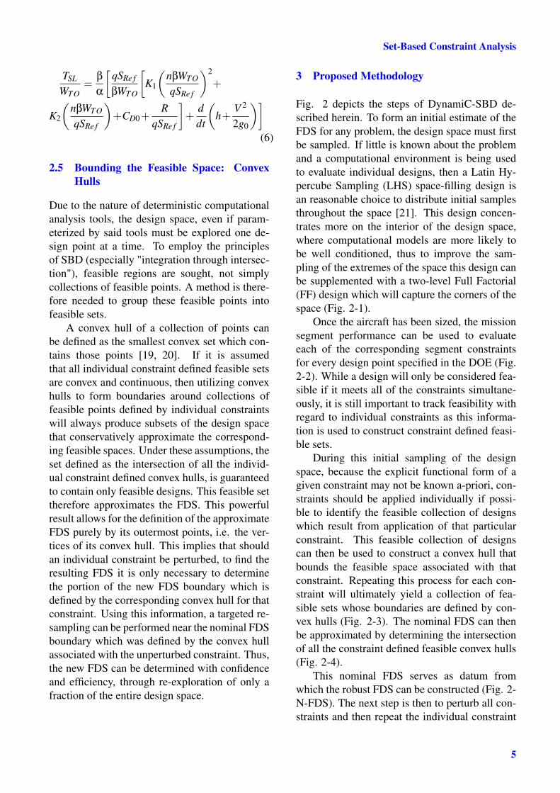
The energy-based constraint analysis is a para-metric physics-based formulation that is multi-disciplinary in nature and useful for aircraft pre-conceptual design. This approach enables thegross sizing of an aircraft through the applica-tion of mission segment specific constraints ex-pressed as functions of the two main design vari-ables considered, thrust to weight (TSL/WTO) andwing loading (WTO/SRe f ). These constraints canbe derived for each mission segment/flight con-dition through the manipulation of a general-ized energy equation (Eqn. 6) which itself arises
from equating specific excess power to the timerate of change of vehicle energy (potential + ki-netic) [18]. This analysis also has the advan-tage of requiring very limited information aboutthe proposed aircraft. The propulsion systemthrust lapse, mission segment weight fractionsand a representative parabolic drag polar providea nearly complete depiction of an aircraft to beevaluated with this analysis.
Ps =(T −D−R)V
W=
ddt
(mg0h+
12
mV 2)
(1)
TW
=(D+R)
W+
ddt
(h+
V 2
2g0
)(2)
D = qSRe f (K1(C2L)+K2(CL)+CD0) (3)
CL =L
qSRe f=
nWqSRe f
(4)
TW
= qSRe f
[K1
(nW
qSRe f
)2
+K2
(nW
qSRe f
)+CD0
+R
qSRe f
]+
ddt
(h+
V 2
2g0
)(5)
4
Set-Based Constraint Analysis
TSL
WTO=
β
α
[qSRe f
βWTO
[K1
(nβWTO
qSRe f
)2
+
K2
(nβWTO
qSRe f
)+CD0+
RqSRe f
]+
ddt
(h+
V 2
2g0
)](6)
2.5 Bounding the Feasible Space: ConvexHulls
Due to the nature of deterministic computationalanalysis tools, the design space, even if param-eterized by said tools must be explored one de-sign point at a time. To employ the principlesof SBD (especially "integration through intersec-tion"), feasible regions are sought, not simplycollections of feasible points. A method is there-fore needed to group these feasible points intofeasible sets.
A convex hull of a collection of points canbe defined as the smallest convex set which con-tains those points [19, 20]. If it is assumedthat all individual constraint defined feasible setsare convex and continuous, then utilizing convexhulls to form boundaries around collections offeasible points defined by individual constraintswill always produce subsets of the design spacethat conservatively approximate the correspond-ing feasible spaces. Under these assumptions, theset defined as the intersection of all the individ-ual constraint defined convex hulls, is guaranteedto contain only feasible designs. This feasible settherefore approximates the FDS. This powerfulresult allows for the definition of the approximateFDS purely by its outermost points, i.e. the ver-tices of its convex hull. This implies that shouldan individual constraint be perturbed, to find theresulting FDS it is only necessary to determinethe portion of the new FDS boundary which isdefined by the corresponding convex hull for thatconstraint. Using this information, a targeted re-sampling can be performed near the nominal FDSboundary which was defined by the convex hullassociated with the unperturbed constraint. Thus,the new FDS can be determined with confidenceand efficiency, through re-exploration of only afraction of the entire design space.
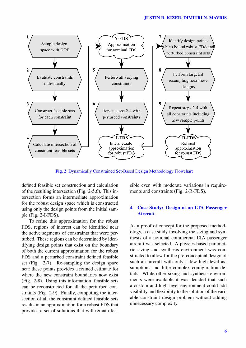
3 Proposed Methodology
Fig. 2 depicts the steps of DynamiC-SBD de-scribed herein. To form an initial estimate of theFDS for any problem, the design space must firstbe sampled. If little is known about the problemand a computational environment is being usedto evaluate individual designs, then a Latin Hy-percube Sampling (LHS) space-filling design isan reasonable choice to distribute initial samplesthroughout the space [21]. This design concen-trates more on the interior of the design space,where computational models are more likely tobe well conditioned, thus to improve the sam-pling of the extremes of the space this design canbe supplemented with a two-level Full Factorial(FF) design which will capture the corners of thespace (Fig. 2-1).
Once the aircraft has been sized, the missionsegment performance can be used to evaluateeach of the corresponding segment constraintsfor every design point specified in the DOE (Fig.2-2). While a design will only be considered fea-sible if it meets all of the constraints simultane-ously, it is still important to track feasibility withregard to individual constraints as this informa-tion is used to construct constraint defined feasi-ble sets.
During this initial sampling of the designspace, because the explicit functional form of agiven constraint may not be known a-priori, con-straints should be applied individually if possi-ble to identify the feasible collection of designswhich result from application of that particularconstraint. This feasible collection of designscan then be used to construct a convex hull thatbounds the feasible space associated with thatconstraint. Repeating this process for each con-straint will ultimately yield a collection of fea-sible sets whose boundaries are defined by con-vex hulls (Fig. 2-3). The nominal FDS can thenbe approximated by determining the intersectionof all the constraint defined feasible convex hulls(Fig. 2-4).
This nominal FDS serves as datum fromwhich the robust FDS can be constructed (Fig. 2-N-FDS). The next step is then to perturb all con-straints and then repeat the individual constraint
5
JUSTIN R. KIZER, DIMITRI N. MAVRIS
Fig. 2 Dynamically Constrained Set-Based Design Methodology Flowchart
defined feasible set construction and calculationof the resulting intersection (Fig. 2-5,6). This in-tersection forms an intermediate approximationfor the robust design space which is constructedusing only the design points from the initial sam-ple (Fig. 2-I-FDS).
To refine this approximation for the robustFDS, regions of interest can be identified nearthe active segments of constraints that were per-turbed. These regions can be determined by iden-tifying design points that exist on the boundaryof both the current approximation for the robustFDS and a perturbed constraint defined feasibleset (Fig. 2-7). Re-sampling the design spacenear these points provides a refined estimate forwhere the new constraint boundaries now exist(Fig. 2-8). Using this information, feasible setscan be reconstructed for all the perturbed con-straints (Fig. 2-9). Finally, computing the inter-section of all the constraint defined feasible setsresults in an approximation for a robust FDS thatprovides a set of solutions that will remain fea-
sible even with moderate variations in require-ments and constraints (Fig. 2-R-FDS).
4 Case Study: Design of an LTA PassengerAircraft
As a proof of concept for the proposed method-ology, a case study involving the sizing and syn-thesis of a notional commercial LTA passengeraircraft was selected. A physics-based paramet-ric sizing and synthesis environment was con-structed to allow for the pre-conceptual design ofsuch an aircraft with only a few high level as-sumptions and little complex configuration de-tails. While other sizing and synthesis environ-ments were available it was decided that sucha custom and high-level environment could addvisibility and flexibility to the solution of the vari-able constraint design problem without addingunnecessary complexity.
6

Set-Based Constraint Analysis
4.1 Mission Definition and Assumptions
The LTA was sized based on a representative mis-sion for the Boeing 777-200ER aircraft. Thedesign range was set to 7440 nmi with a de-sign payload of 300 passengers. The flight pro-file is divided into 11 primary mission segmentswith sub-segments defined for the climb to ini-tial cruise altitude and descent primary segments.The flight profile is described in table 1.
Table 1 Custom LTA Mission SegmentsSegment No. Description
1. Start and Taxi out2. Full Power Takeoff at SL
3.1 Accelerate to M = 0.53.2 Climb to 10,000 ft3.3 Accelerate to M = 0.743.4 Climb to 31,000 ft3.5 Accelerate to M = MCruise4. Cruise at 31,000 ft5. Climb to 35,000 ft6. Cruise at 35,000 ft7. Climb to 39,000 ft8. Cruise at 39,000 ft
9.1 Decelerate to M = 0.759.2 Descend to 21,000 ft9.3 Decelerate to M = 0.59.4 Descend to SL9.5 Decelerate to V = VLand)10. Land at SL11. Taxi in and Shut-off
4.2 Propulsion System
The propulsion system used to size the LTA wasmodelled using a state of the art computationalpropulsion simulation system. From this anal-ysis, engine model performance was calibratedusing publicly available data to produce an en-gine deck representative of the performance ofthe GE90-94B turbofan engine. Regressionsfor three engine power settings were then con-structed from this tabular engine deck to provideexpressions for thrust, ram drag and Thrust Spe-cific Fuel Consumption (TSFC) as a function ofaltitude and Mach number. These regressionsenabled a much more accurate prediction of thepropulsion system thrust lapse for the variousmission segments.
4.3 Aerodynamics
The aerodynamics used to size the LTA werederived from NASA FLight Optimization Sys-tem (FLOPS) generated aerodynamics data for abaseline LTA model which provided drag coeffi-cient values as a function of altitude, Mach num-ber and lift coefficient [22]. This data was used toconstruct parabolic drag polars to establish val-ues of K1, K2 and CD0 at the appropriate flightcondition for a given mission segment.
4.4 Fuel Balance
The overall sizing and Takeoff Gross Weight(WTO) estimation of the LTA was determined us-ing an iterative fuel balance approach. For eachiteration, the aircraft began with estimated val-ues for fuel weight, WTO and maximum TSL.The aircraft (modelled as a point mass) was thenflown through each simulated mission segment inwhich flight conditions, forces, accelerations andmass changes were computed [23]. Once the air-craft had completed all mission segments as pre-scribed, the actual and required fuel weights werecompared. If the discrepancy in fuel weight wasnot within a prescribed tolerance, new guessesfor weight and thrust values were computed andthe next iteration initiated. Once the weight toler-ance was reached, the vehicle was determined tobe converged and was then utilized to provide in-put for the energy-based constraint analysis. Theattributes of the converged LTA are shown con-trasted to a FLOPS 777-200ER baseline modelin table 2.
Table 2 LTA Design Point ComparisonParameter Custom FLOPS BaselineTSL/WTO 0.3004 0.2966WTO/SRe f [psf] 132.8 132.8WFuel [lbs] 271,903 271,916OEW [lbs] 320,078 320,764TOGW [lbs] 660,623 655,891Range [nmi] 7453 7440
5 Results
Once the vehicle sizing was complete the energy-based constraint equations were applied for each
7
JUSTIN R. KIZER, DIMITRI N. MAVRIS
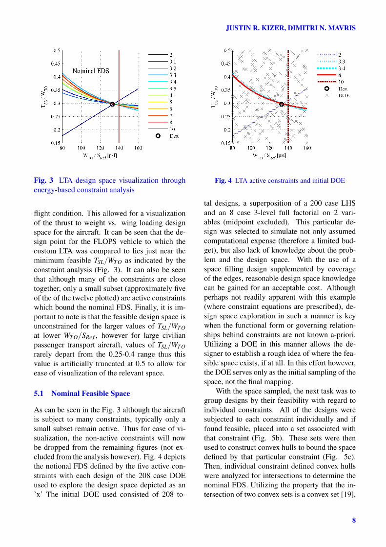
Fig. 3 LTA design space visualization throughenergy-based constraint analysis
flight condition. This allowed for a visualizationof the thrust to weight vs. wing loading designspace for the aircraft. It can be seen that the de-sign point for the FLOPS vehicle to which thecustom LTA was compared to lies just near theminimum feasible TSL/WTO as indicated by theconstraint analysis (Fig. 3). It can also be seenthat although many of the constraints are closetogether, only a small subset (approximately fiveof the of the twelve plotted) are active constraintswhich bound the nominal FDS. Finally, it is im-portant to note is that the feasible design space isunconstrained for the larger values of TSL/WTOat lower WTO/SRe f , however for large civilianpassenger transport aircraft, values of TSL/WTOrarely depart from the 0.25-0.4 range thus thisvalue is artificially truncated at 0.5 to allow forease of visualization of the relevant space.
5.1 Nominal Feasible Space
As can be seen in the Fig. 3 although the aircraftis subject to many constraints, typically only asmall subset remain active. Thus for ease of vi-sualization, the non-active constraints will nowbe dropped from the remaining figures (not ex-cluded from the analysis however). Fig. 4 depictsthe notional FDS defined by the five active con-straints with each design of the 208 case DOEused to explore the design space depicted as an’x’ The initial DOE used consisted of 208 to-
Fig. 4 LTA active constraints and initial DOE
tal designs, a superposition of a 200 case LHSand an 8 case 3-level full factorial on 2 vari-ables (midpoint excluded). This particular de-sign was selected to simulate not only assumedcomputational expense (therefore a limited bud-get), but also lack of knowledge about the prob-lem and the design space. With the use of aspace filling design supplemented by coverageof the edges, reasonable design space knowledgecan be gained for an acceptable cost. Althoughperhaps not readily apparent with this example(where constraint equations are prescribed), de-sign space exploration in such a manner is keywhen the functional form or governing relation-ships behind constraints are not known a-priori.Utilizing a DOE in this manner allows the de-signer to establish a rough idea of where the fea-sible space exists, if at all. In this effort however,the DOE serves only as the initial sampling of thespace, not the final mapping.
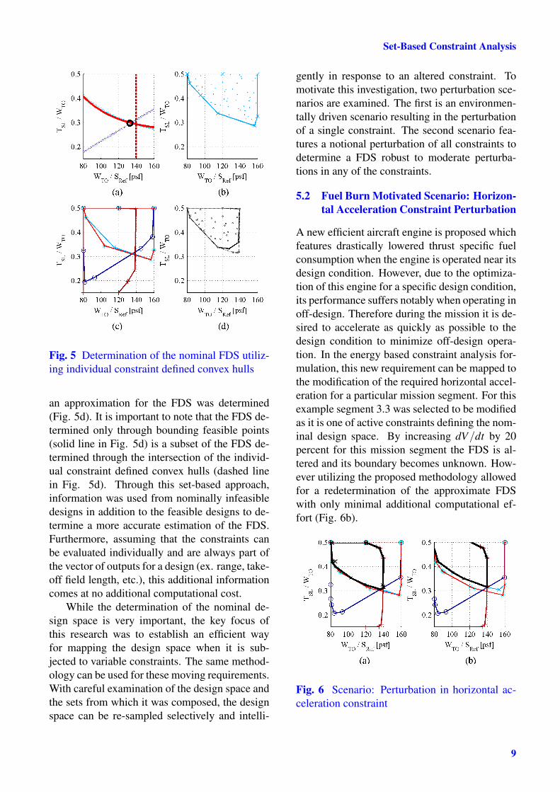
With the space sampled, the next task was togroup designs by their feasibility with regard toindividual constraints. All of the designs weresubjected to each constraint individually and iffound feasible, placed into a set associated withthat constraint (Fig. 5b). These sets were thenused to construct convex hulls to bound the spacedefined by that particular constraint (Fig. 5c).Then, individual constraint defined convex hullswere analyzed for intersections to determine thenominal FDS. Utilizing the property that the in-tersection of two convex sets is a convex set [19],
8
Set-Based Constraint Analysis
Fig. 5 Determination of the nominal FDS utiliz-ing individual constraint defined convex hulls
an approximation for the FDS was determined(Fig. 5d). It is important to note that the FDS de-termined only through bounding feasible points(solid line in Fig. 5d) is a subset of the FDS de-termined through the intersection of the individ-ual constraint defined convex hulls (dashed linein Fig. 5d). Through this set-based approach,information was used from nominally infeasibledesigns in addition to the feasible designs to de-termine a more accurate estimation of the FDS.Furthermore, assuming that the constraints canbe evaluated individually and are always part ofthe vector of outputs for a design (ex. range, take-off field length, etc.), this additional informationcomes at no additional computational cost.
While the determination of the nominal de-sign space is very important, the key focus ofthis research was to establish an efficient wayfor mapping the design space when it is sub-jected to variable constraints. The same method-ology can be used for these moving requirements.With careful examination of the design space andthe sets from which it was composed, the designspace can be re-sampled selectively and intelli-
gently in response to an altered constraint. Tomotivate this investigation, two perturbation sce-narios are examined. The first is an environmen-tally driven scenario resulting in the perturbationof a single constraint. The second scenario fea-tures a notional perturbation of all constraints todetermine a FDS robust to moderate perturba-tions in any of the constraints.
5.2 Fuel Burn Motivated Scenario: Horizon-tal Acceleration Constraint Perturbation
A new efficient aircraft engine is proposed whichfeatures drastically lowered thrust specific fuelconsumption when the engine is operated near itsdesign condition. However, due to the optimiza-tion of this engine for a specific design condition,its performance suffers notably when operating inoff-design. Therefore during the mission it is de-sired to accelerate as quickly as possible to thedesign condition to minimize off-design opera-tion. In the energy based constraint analysis for-mulation, this new requirement can be mapped tothe modification of the required horizontal accel-eration for a particular mission segment. For thisexample segment 3.3 was selected to be modifiedas it is one of active constraints defining the nom-inal design space. By increasing dV/dt by 20percent for this mission segment the FDS is al-tered and its boundary becomes unknown. How-ever utilizing the proposed methodology allowedfor a redetermination of the approximate FDSwith only minimal additional computational ef-fort (Fig. 6b).
Fig. 6 Scenario: Perturbation in horizontal ac-celeration constraint
9
JUSTIN R. KIZER, DIMITRI N. MAVRIS
5.3 Finding the Robust FDS: All ConstraintsPerturbed
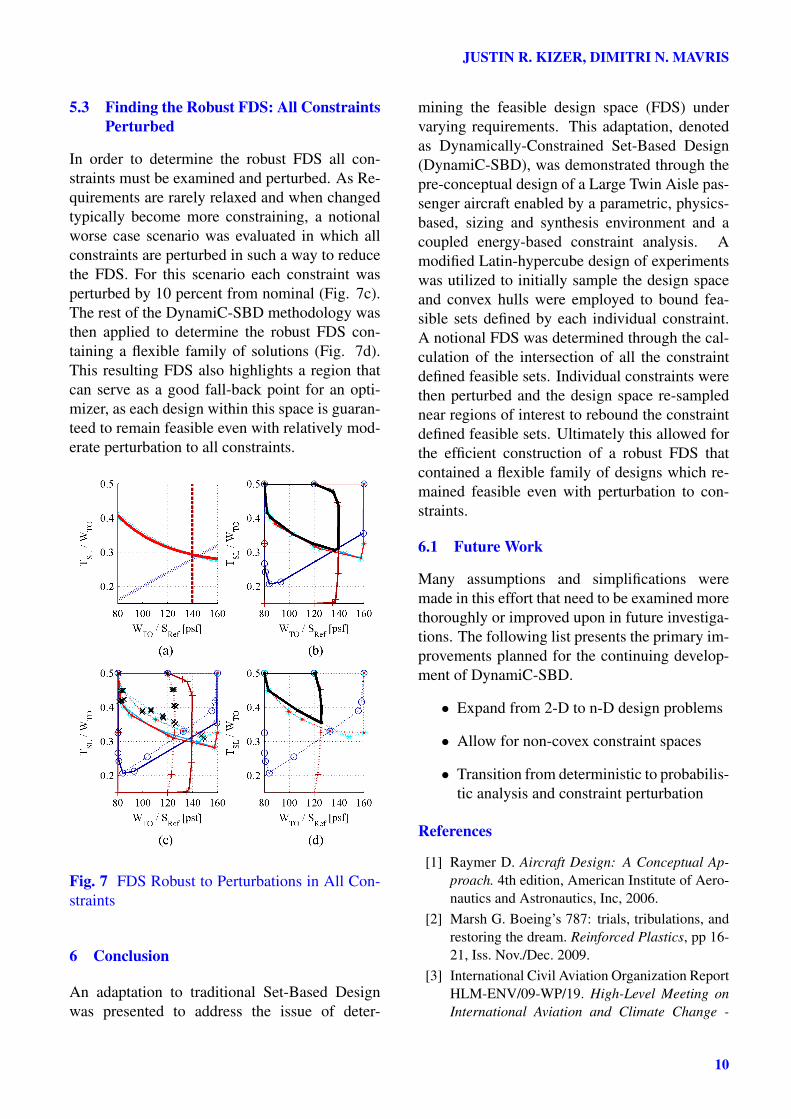
In order to determine the robust FDS all con-straints must be examined and perturbed. As Re-quirements are rarely relaxed and when changedtypically become more constraining, a notionalworse case scenario was evaluated in which allconstraints are perturbed in such a way to reducethe FDS. For this scenario each constraint wasperturbed by 10 percent from nominal (Fig. 7c).The rest of the DynamiC-SBD methodology wasthen applied to determine the robust FDS con-taining a flexible family of solutions (Fig. 7d).This resulting FDS also highlights a region thatcan serve as a good fall-back point for an opti-mizer, as each design within this space is guaran-teed to remain feasible even with relatively mod-erate perturbation to all constraints.
Fig. 7 FDS Robust to Perturbations in All Con-straints
6 Conclusion
An adaptation to traditional Set-Based Designwas presented to address the issue of deter-
mining the feasible design space (FDS) undervarying requirements. This adaptation, denotedas Dynamically-Constrained Set-Based Design(DynamiC-SBD), was demonstrated through thepre-conceptual design of a Large Twin Aisle pas-senger aircraft enabled by a parametric, physics-based, sizing and synthesis environment and acoupled energy-based constraint analysis. Amodified Latin-hypercube design of experimentswas utilized to initially sample the design spaceand convex hulls were employed to bound fea-sible sets defined by each individual constraint.A notional FDS was determined through the cal-culation of the intersection of all the constraintdefined feasible sets. Individual constraints werethen perturbed and the design space re-samplednear regions of interest to rebound the constraintdefined feasible sets. Ultimately this allowed forthe efficient construction of a robust FDS thatcontained a flexible family of designs which re-mained feasible even with perturbation to con-straints.
6.1 Future Work
Many assumptions and simplifications weremade in this effort that need to be examined morethoroughly or improved upon in future investiga-tions. The following list presents the primary im-provements planned for the continuing develop-ment of DynamiC-SBD.
• Expand from 2-D to n-D design problems
• Allow for non-covex constraint spaces
• Transition from deterministic to probabilis-tic analysis and constraint perturbation
References
[1] Raymer D. Aircraft Design: A Conceptual Ap-proach. 4th edition, American Institute of Aero-nautics and Astronautics, Inc, 2006.
[2] Marsh G. Boeing’s 787: trials, tribulations, andrestoring the dream. Reinforced Plastics, pp 16-21, Iss. Nov./Dec. 2009.
[3] International Civil Aviation Organization ReportHLM-ENV/09-WP/19. High-Level Meeting onInternational Aviation and Climate Change -
10
Set-Based Constraint Analysis
Agenda Item 1: Aspirational Goals and Imple-mentation Options Montreal, Revision 1, Oct.2009.
[4] International Civil Aviation Organization Re-port HLM-ENV/09-WP/1. High-Level Meetingon International Aviation and Climate Change -Agenda Item 5: Review of Programme of Actionon International Aviation and Climate Changeand Recommendations to COP15. Montreal, Re-vision 2, Oct. 2009.
[5] Guynn M and Berton J. Advanced Single-AisleTransport Propulsion Design Options Revisited.2103 Aviation Technology, Integration, and Op-erations Conference, Los Angeles, CA, AIAA2013-4330, 2013.
[6] Malak Jr R, Aughenbaugh J and Paredis C.Multi-attribute utility analysis in set-based con-ceptual design. CAD Computer Aided Design,Vol. 41, No. 3, pp 214-227, 2009.
[7] Liker J. The Toyota Way: 14 Management Prin-ciples from the World’s Greatest Manufacturer.1st edition, McGraw-Hill, 2004.
[8] Hopp W, and Spearman M. Factory Physics. 3rdedition, McGraw-Hill Irwin, 2008.
[9] Mavris D, DeLaurentis D, Bandte O and HaleM. A Stochastic Approach to Multi-disciplinaryAircraft Analysis and Design. 36th AerospaceSciences Meeting and Exhibit, Reno, NV, AIAA98-0912, 1998.
[10] Ward A, Liker J, Cristiano J, and Sobek D II.The Second Toyota Paradox: How DelayingDecisions Can Make Better Cars Faster. SloanManagement Review, Vol. 36, No. 2, pp. 43-61,1995.
[11] Sobek II, D, Ward A, and Liker J. Toyota’sprinciples of set-based concurrent engineering.Sloan Management Review, Vol. 40, No. 2, pp67-83, 1999.
[12] Gray A. Enhancement of Set-Based De-sign Practices Via Introduction of UncertaintyThrough the Use of Interval Type-2 Model-ing and General Type-2 Fuzzy Logic AgentBased Methods. Ph.D. Dissertation, Naval Ar-chitecture and Marine Engineering, Universityof Michigan. 2011.
[13] Stoll R. Sets, Logic and Axiomatic Theories. 2ndedition, W. H. Freeman and Company, 1974.
[14] Fisher R. The Design of Experiments. 8th edi-tion, Oliver and Boyd, 1966.
[15] Giunta A, Wojtkiewicz S and Eldred M.Overview of Modern Design of ExperimentMethods for Computational Simulations. 41stAerospace Sciences Meeting and Exhibit, Reno,NV, AIAA 2003-649, 2003.
[16] Cox D, and Reid N. The Theory of Design ofExperiments. Chapman and Hall/CRC, 2000.
[17] Frits A and Mavris D. A Screening Method forCustomizing Designs Around Non-ConvergentRegions of Design Spaces. 9th AIAA/ISSMOSymposium on Multidisciplinary Analysis andOptimization, Atlanta, GA, AIAA 2002-5572,2002.
[18] Mattingly J, Heiser W and Daley D. Aircraft En-gine Design. 1st edition, American Institute ofAeronautics and Astronautics, Inc, 1987.
[19] de Berg M, Cheong O, van Kreveld M and Over-mars M. Computational Geometry: Algorithmsand Applications. 3rd edition, Springer, 2008.
[20] Missoum S, Ramu P and Haftka R. A convexhull approach for the reliability-based design op-timization of nonlinear transient dynamic prob-lems. Computer Methods In Applied MechanicsAnd Engineering, Vol. 196, No. 29-30, pp 2895-2906, 2007.
[21] Swiler L, Slepoy R and Guinta A. Eval-uation of Sampling Methods in Construct-ing Response Surface Approximations. 47thAIAA/ASME/ASCE/AHS/ASC Structures, Struc-tural Dynamics, and Materials Conference,Newport, RI, AIAA 2006-1827, 2006
[22] MucCullers L. Aircraft Configuration Optimiza-tion Including Optimized Flight Profiles. Sym-posium on Recent Experiences in Multidisci-plinary Analysis and Optimization, NASA CP-2327, pp 395-412, 1984.
[23] Saarlas M. Aircraft Performance. 1st edition,John Wiley and Sons, Inc, 2007.
7 Contact Author Email Address
Justin R. Kizermailto: [email protected]
Copyright Statement
The authors confirm that they, and/or their company or or-ganization, hold copyright on all of the original materialincluded in this paper. The authors also confirm that they
11

JUSTIN R. KIZER, DIMITRI N. MAVRIS
have obtained permission, from the copyright holder of anythird party material included in this paper, to publish it aspart of their paper. The authors confirm that they give per-mission, or have obtained permission from the copyrightholder of this paper, for the publication and distribution ofthis paper as part of the ICAS 2014 proceedings or as indi-vidual off-prints from the proceedings.
12