Embed Size (px)
Citation preview

Congratulations on your purchase of a new OneShot chassis! The PC01 OneShot combines a rugged enclosure, power supply, and discrete instrument DI in a compact 1/4U package. A few minutes of assembly are all that is required to ensure years of reliable service. Who Should Build This Kit? The PC01 is not difficult to assemble, but it is not intended for absolute beginners. If you’ve never built an electronic project before, this is probably not the one to start with. To guarantee success, make sure you have:
The ability to make basic voltage and resistance measurements using a digital multi-meter (DMM).
At least a rudimentary understanding of voltage, current, and resistance.
Some experience soldering on printed circuit boards.
The patience to follow instructions precisely and work carefully. Essential Tools Fine tipped 20-30 watt soldering iron w/ cleaning sponge (Hakko 936 or similar) Eutectic (63/37) rosin core or “no clean” solder (.025” diameter is usually best) Small needle nose pliers Small diagonal cutters Wire stripper Phillips screwdriver (#1) 3/32” Hex Driver Highly Recommended Tools ½” Socket Work Area Find a clean, stable, well-lit work surface. An anti-static mat is highly recommended for this project. Good lighting will make assembly much easier. Soldering Technique Make sure your iron's tip is tinned properly, and keep it clean! The trick to making perfect solder joints is to heat the joint quickly and thoroughly before applying the solder, and a properly tinned and clean tip is essential for this. Apply just enough solder to thoroughly encapsulate the joint, but don’t use too much. The finished joint should be smooth and shiny, not rough or gritty looking.
Instruction Conventions
Text in orange indicates a step where extra care needs to be taken. Doing it wrong isn’t a disaster, but it’ll need to be corrected.
Text in red indicates a step that must be done correctly. Doing it wrong will guarantee improper operation, and probably damage components and/or the circuit board.
Prepare the Module
The OneShot power supply board includes three relays that enable several optional features. To take advantage of these features, most current preamp modules will require some modifications. If you are not comfortable referring to the schematics, removing parts, wiring jumpers, and possibly cutting PCB traces, do not attempt these modifications yourself. You can always use the DI by using an external XLR jumper between the DI output and preamp input if you do not want to make modifications to your module.
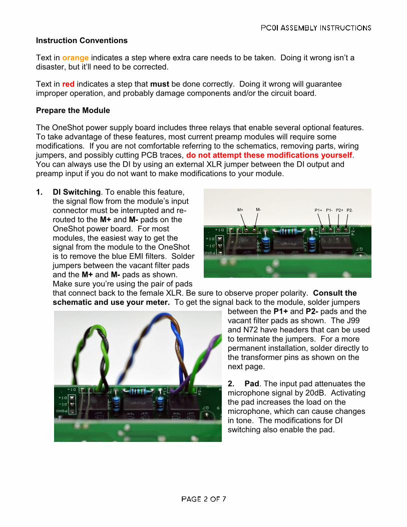
1. DI Switching. To enable this feature, the signal flow from the module’s input connector must be interrupted and re-routed to the M+ and M- pads on the OneShot power board. For most modules, the easiest way to get the signal from the module to the OneShot is to remove the blue EMI filters. Solder jumpers between the vacant filter pads and the M+ and M- pads as shown. Make sure you’re using the pair of pads that connect back to the female XLR. Be sure to observe proper polarity. Consult the schematic and use your meter. To get the signal back to the module, solder jumpers
between the P1+ and P2- pads and the vacant filter pads as shown. The J99 and N72 have headers that can be used to terminate the jumpers. For a more permanent installation, solder directly to the transformer pins as shown on the next page.
2. Pad. The input pad attenuates the microphone signal by 20dB. Activating the pad increases the load on the microphone, which can cause changes in tone. The modifications for DI switching also enable the pad.

3. Input Z. To enable input impedance switching, solder jumpers from the P1- and P2+ pads on the OneShot to the appropriate transformer terminals on your module. Keep in mind that only modules with split-primary input transformers, namely the N72 and J99, will work with the “Input Z” switch. Both of these modules have headers that can be used to terminate the jumpers.
4. Modified N72 and OneShot boards ready for installation in the chassis.
Input Transformer Terminal Numbering – See Schematics
P1+ P1- P2+ P2-
J99 1 2 4 3
N72 2 4 3 5

Assembly
5. Before you begin, carefully unpack the kit and examine the parts. Check the contents of each small bag against the BOM to make sure all the parts have been included. If you think something’s missing, please e-mail the details to [email protected] and we’ll ship replacement parts ASAP.
6. Arrange the chassis bottom on the bench as shown. The bottom and top are identical, except the bottom has more holes.
7. Insert a #4-40 x 5/8” flat head screw through the appropriate hole. Use a ¼” nylon spacer between the chassis and the power supply board as shown.
8. Orient the power supply and DI circuit boards with the XLR connector toward the back. Align the 1” hex spacer between the boards as shown. Thread the 5/8” screw through the power supply board into the spacer. Leave the screw a bit loose at this point. Use the other 5/8” screw to secure the
DI board temporarily.
9. If your module has an output transformer, select the appropriate mounting screws and run them through the holes that align with the circuit board. Use 4x 1½” screws for an N72. Use 2x 1¼” for an A12B or J99B. If you have an older module, you may have to drill your own holes.
10. Slide ¼” nylon spacers over the screws and run them through the module PCB and output transformer. Don’t forget any spacers needed between the PCB and transformer. This may require a bit of patience, but you only have to do it once.
11. Run #4 keps nuts onto the screws as shown. Leave the nuts a bit loose at this point.

12. Maneuver the rear panel over the XLR connectors and into position as shown. Use 2x M2.5 x 6mm screws to secure the panel to the XLR connectors. Use 2x #4 x 1/8” flat head screws to attach the rear panel to the bottom half of the chassis.
13. Install the black shoulder washer with the shoulder facing away from the body of the power jack as shown. The metal bushing should not make contact with the panel. Do not over-tighten the panel nut.
14. Install the power jack using the flat fiber washer, flat metal washer, and panel nut as shown.
15. Attach the front sub-panel in a similar fashion to the back. Take care not to push the LED into the chassis. Use 2x #4 x 1/8” flat head screws to attach the front panel to the bottom half of the chassis.
16. Snug the screws left loose in the steps above. Don’t over-tighten! A drop of blue Loctite on the transformer nut threads is a good idea.

17. Align a ¼” nylon spacer with the hole in the DI board as shown.
18. Without disturbing the spacer, maneuver the top half of the chassis into place. Drop the remaining #4-40 x 5/8” screw through the cover, standoff, and DI board and thread it into the aluminum spacer below.
19. Use the remaining 1/8” screws to assemble the chassis.
20. Carefully work the aluminum front panel over all of the shafts and bushings and secure with 4x #4-40 black cap screws as shown. Take care to align the LED so it protrudes through the hole in the panel.
21. Install the serrated washers and panel nuts. Carefully snug the nuts using a ½” socket and finger torque only. Leave the ratchet wrench in the toolbox. Cover the end of the socket with a few small bits of tape to avoid scratching the panel.

22. Install and align the knobs.
23. Using the #4-40 x 3/16” screws, attach the feet.
24. If mounting to a universal shelf, use the same screws with a drop of blue Loctite on the threads. Don’t over-tighten the screws! Don’t use longer screws! You may damage the circuit board.
25. Congratulations! You’ve got an assembled OneShot preamp.


![Pinocchia oneshot [hq point]](https://img.pdfslide.net/doc/110x75/579055141a28ab900c9357c3/pinocchia-oneshot-hq-point.jpg)


![[Mangá] Gokiburi buster (oneshot)](https://img.pdfslide.net/doc/110x75/579054321a28ab900c8f82f1/manga-gokiburi-buster-oneshot.jpg)

![The last supper [oneshot][ama scans]](https://img.pdfslide.net/doc/110x75/57906e171a28ab687492dda1/the-last-supper-oneshotama-scans.jpg)

![Gokujou Beef Curry Himitsu Iri ONESHOT c03 [TL Coffee] - Copy](https://img.pdfslide.net/doc/110x75/55cf8fdd550346703ba0ab1d/gokujou-beef-curry-himitsu-iri-oneshot-c03-tl-coffee-copy.jpg)

![[DPnF] Yuru Yuri Oneshot](https://img.pdfslide.net/doc/110x75/577cd9a11a28ab9e78a3c89a/dpnf-yuru-yuri-oneshot.jpg)