Embed Size (px)
Citation preview

SGSM 3000, SGCM 3000 & SGCO 3000
TK 53414-4-MM (Rev. 1, 07/07)
Copyright© 2007 Thermo King Corp., Minneapolis, MN, USA.Printed in USA.

This manual is published for informational purposes only and the information so provided should not be considered as all-inclusive or covering all contingencies. If further information is required, Thermo King Corporation should be consulted.
Sale of product shown in this manual is subject to Thermo King’s terms and conditions including, but not limited to, the Thermo King Limited Express Warranty. Such terms and conditions are available upon request. Thermo King’s warranty will not apply to any equipment which has been “so repaired or altered outside the manufacturer’s plants as, in the manufacturer’s judgment, to effect its stability.”
No warranties, express or implied, including warranties of fitness for a particular purpose or merchantability, or warranties arising from course of dealing or usage of trade, are made regarding the information, recommendations, and descriptions contained herein. Manufacturer is not responsible and will not be held liable in contract or in tort (including negligence) for any special, indirect or consequential damages, including injury or damage caused to vehicles, contents or persons, by reason of the installation of any Thermo King product or its mechanical failure.
The maintenance information in this manual covers unit models:
SGCO (062007): Model with SG+ controls and clip-on unit frame SGSM (062008): Model with SG+ controls and side-mount unit frame SGCO (062009) Model with SG+ controls and clip-on unit frame SGCM (062010): Model with SG+ controls and center-mount unit frame
For further information, refer to:
SGCO 3000 Parts Manual SGSM 3000 Parts Manual SGCM 3000 Parts Manual TK482 and TK486 Engine Overhaul Manual Electrostatic Discharge (ESD) Training Guide Tool Catalog
TK 53717TK 53706TK 53725TK 50136TK 40282TK 5955
The information in this manual is provided to assist owners, operators and service people in the proper upkeep and maintenance of Thermo King units. The Thermo King family of generator sets includes three models: SGSM, SGCM and SGCO. When maintenance information differs between models, this manual uses the model nomenclature (e.g. SGSM) to indicate that the information applies to specific units only. In addition, the model nomenclature indicates the following:
Model Nomenclature Unit Feature
SM............................................ Side-mount unit frameCM.........................................Center-mount unit frameCO................................................... Clip-on unit frame

Recover Refrigerant
At Thermo King, we recognize the need to preserve the environment and limit the potential harm to the ozone layer that can result from allowing refrigerant to escape into the atmosphere.
We strictly adhere to a policy that promotes the recovery and limits the loss of refrigerant into the atmosphere.
In addition, service personnel must be aware of Federal regulations concerning the use of refrigerants and the certification of technicians. For additional information on regulations and technician certification programs, contact your local Thermo King dealer.


Table of Contents
List of Figures . . . . . . . . . . . . . . . . . . . . . . . . . . . . . . . . . . . . . . . . . . . . . . . . . . . . . . . . . . . . . . . . . . . . . . . . . . . 9
Genset Model Features . . . . . . . . . . . . . . . . . . . . . . . . . . . . . . . . . . . . . . . . . . . . . . . . . . . . . . . . . . . . . . . . . . 11
Safety Precautions . . . . . . . . . . . . . . . . . . . . . . . . . . . . . . . . . . . . . . . . . . . . . . . . . . . . . . . . . . . . . . . . . . . . . . 13General Practices . . . . . . . . . . . . . . . . . . . . . . . . . . . . . . . . . . . . . . . . . . . . . . . . . . . . . . . . . . . . . . . . . . . . . . . . 13Battery Hazards . . . . . . . . . . . . . . . . . . . . . . . . . . . . . . . . . . . . . . . . . . . . . . . . . . . . . . . . . . . . . . . . . . . . . . . . . 13
Precautions . . . . . . . . . . . . . . . . . . . . . . . . . . . . . . . . . . . . . . . . . . . . . . . . . . . . . . . . . . . . . . . . . . . . . . . . . . 13First Aid . . . . . . . . . . . . . . . . . . . . . . . . . . . . . . . . . . . . . . . . . . . . . . . . . . . . . . . . . . . . . . . . . . . . . . . . . . . . 13
Electrical Hazards . . . . . . . . . . . . . . . . . . . . . . . . . . . . . . . . . . . . . . . . . . . . . . . . . . . . . . . . . . . . . . . . . . . . . . . . 13High Voltage . . . . . . . . . . . . . . . . . . . . . . . . . . . . . . . . . . . . . . . . . . . . . . . . . . . . . . . . . . . . . . . . . . . . . . . . . 13Precautions . . . . . . . . . . . . . . . . . . . . . . . . . . . . . . . . . . . . . . . . . . . . . . . . . . . . . . . . . . . . . . . . . . . . . . . . . . 14First Aid . . . . . . . . . . . . . . . . . . . . . . . . . . . . . . . . . . . . . . . . . . . . . . . . . . . . . . . . . . . . . . . . . . . . . . . . . . . . 14Low Voltage . . . . . . . . . . . . . . . . . . . . . . . . . . . . . . . . . . . . . . . . . . . . . . . . . . . . . . . . . . . . . . . . . . . . . . . . . 14
General Safety Precautions for Servicing Units (or Containers) Equipped with a Microprocessor Controller . . 15Controller Repair . . . . . . . . . . . . . . . . . . . . . . . . . . . . . . . . . . . . . . . . . . . . . . . . . . . . . . . . . . . . . . . . . . . . . 15Welding of Units or Containers . . . . . . . . . . . . . . . . . . . . . . . . . . . . . . . . . . . . . . . . . . . . . . . . . . . . . . . . . . . 15
Safety Do’s and Don’ts . . . . . . . . . . . . . . . . . . . . . . . . . . . . . . . . . . . . . . . . . . . . . . . . . . . . . . . . . . . . . . . . . . . . 15DO: . . . . . . . . . . . . . . . . . . . . . . . . . . . . . . . . . . . . . . . . . . . . . . . . . . . . . . . . . . . . . . . . . . . . . . . . . . . . . . . . 15DO NOT . . . . . . . . . . . . . . . . . . . . . . . . . . . . . . . . . . . . . . . . . . . . . . . . . . . . . . . . . . . . . . . . . . . . . . . . . . . . 16
Serial Number Locations . . . . . . . . . . . . . . . . . . . . . . . . . . . . . . . . . . . . . . . . . . . . . . . . . . . . . . . . . . . . . . . . . . . 17Unit Decals . . . . . . . . . . . . . . . . . . . . . . . . . . . . . . . . . . . . . . . . . . . . . . . . . . . . . . . . . . . . . . . . . . . . . . . . . . . . . 18
Service Guide . . . . . . . . . . . . . . . . . . . . . . . . . . . . . . . . . . . . . . . . . . . . . . . . . . . . . . . . . . . . . . . . . . . . . . . . . . 21
Specifications . . . . . . . . . . . . . . . . . . . . . . . . . . . . . . . . . . . . . . . . . . . . . . . . . . . . . . . . . . . . . . . . . . . . . . . . . . 23Engine . . . . . . . . . . . . . . . . . . . . . . . . . . . . . . . . . . . . . . . . . . . . . . . . . . . . . . . . . . . . . . . . . . . . . . . . . . . . . . . . . 23Generator . . . . . . . . . . . . . . . . . . . . . . . . . . . . . . . . . . . . . . . . . . . . . . . . . . . . . . . . . . . . . . . . . . . . . . . . . . . . . . 23Electrical Control System . . . . . . . . . . . . . . . . . . . . . . . . . . . . . . . . . . . . . . . . . . . . . . . . . . . . . . . . . . . . . . . . . . 24Electrical Components . . . . . . . . . . . . . . . . . . . . . . . . . . . . . . . . . . . . . . . . . . . . . . . . . . . . . . . . . . . . . . . . . . . . 24Controller Default Settings . . . . . . . . . . . . . . . . . . . . . . . . . . . . . . . . . . . . . . . . . . . . . . . . . . . . . . . . . . . . . . . . . 24Physical Specifications . . . . . . . . . . . . . . . . . . . . . . . . . . . . . . . . . . . . . . . . . . . . . . . . . . . . . . . . . . . . . . . . . . . . 25Physical Specifications . . . . . . . . . . . . . . . . . . . . . . . . . . . . . . . . . . . . . . . . . . . . . . . . . . . . . . . . . . . . . . . . . . . . 26Physical Specifications . . . . . . . . . . . . . . . . . . . . . . . . . . . . . . . . . . . . . . . . . . . . . . . . . . . . . . . . . . . . . . . . . . . . 27Metric Hardware Torque Charts . . . . . . . . . . . . . . . . . . . . . . . . . . . . . . . . . . . . . . . . . . . . . . . . . . . . . . . . . . . . . 28
Unit Description, Features & Options . . . . . . . . . . . . . . . . . . . . . . . . . . . . . . . . . . . . . . . . . . . . . . . . . . . . . . . 29General Description . . . . . . . . . . . . . . . . . . . . . . . . . . . . . . . . . . . . . . . . . . . . . . . . . . . . . . . . . . . . . . . . . . . . . . 29EMI 3000 Package . . . . . . . . . . . . . . . . . . . . . . . . . . . . . . . . . . . . . . . . . . . . . . . . . . . . . . . . . . . . . . . . . . . . . . . 30SG+ Microprocessor Controller . . . . . . . . . . . . . . . . . . . . . . . . . . . . . . . . . . . . . . . . . . . . . . . . . . . . . . . . . . . . . . 30Unit Instruments . . . . . . . . . . . . . . . . . . . . . . . . . . . . . . . . . . . . . . . . . . . . . . . . . . . . . . . . . . . . . . . . . . . . . . . . . 30Unit Protection Devices . . . . . . . . . . . . . . . . . . . . . . . . . . . . . . . . . . . . . . . . . . . . . . . . . . . . . . . . . . . . . . . . . . . . 31Dual Voltage Option . . . . . . . . . . . . . . . . . . . . . . . . . . . . . . . . . . . . . . . . . . . . . . . . . . . . . . . . . . . . . . . . . . . . . . 31EcoPower Option . . . . . . . . . . . . . . . . . . . . . . . . . . . . . . . . . . . . . . . . . . . . . . . . . . . . . . . . . . . . . . . . . . . . . . . . 31Fuel Level Sensor Option . . . . . . . . . . . . . . . . . . . . . . . . . . . . . . . . . . . . . . . . . . . . . . . . . . . . . . . . . . . . . . . . . . 31Additional Options . . . . . . . . . . . . . . . . . . . . . . . . . . . . . . . . . . . . . . . . . . . . . . . . . . . . . . . . . . . . . . . . . . . . . . . . 31
Controller Description . . . . . . . . . . . . . . . . . . . . . . . . . . . . . . . . . . . . . . . . . . . . . . . . . . . . . . . . . . . . . . . . . . . 37SG+ Controller Description . . . . . . . . . . . . . . . . . . . . . . . . . . . . . . . . . . . . . . . . . . . . . . . . . . . . . . . . . . . . . . . . . 37Controller Overview . . . . . . . . . . . . . . . . . . . . . . . . . . . . . . . . . . . . . . . . . . . . . . . . . . . . . . . . . . . . . . . . . . . . . . 39Miscellaneous Features . . . . . . . . . . . . . . . . . . . . . . . . . . . . . . . . . . . . . . . . . . . . . . . . . . . . . . . . . . . . . . . . . . . 40
Navigating the Controller Menus . . . . . . . . . . . . . . . . . . . . . . . . . . . . . . . . . . . . . . . . . . . . . . . . . . . . . . . . . . . 41Controller Display Menus . . . . . . . . . . . . . . . . . . . . . . . . . . . . . . . . . . . . . . . . . . . . . . . . . . . . . . . . . . . . . . . . . . 41Navigating Controller Menus . . . . . . . . . . . . . . . . . . . . . . . . . . . . . . . . . . . . . . . . . . . . . . . . . . . . . . . . . . . . . . . . 41
Menu Overview . . . . . . . . . . . . . . . . . . . . . . . . . . . . . . . . . . . . . . . . . . . . . . . . . . . . . . . . . . . . . . . . . . . . . . . 42Data Menu . . . . . . . . . . . . . . . . . . . . . . . . . . . . . . . . . . . . . . . . . . . . . . . . . . . . . . . . . . . . . . . . . . . . . . . . . . 43Alarm List Menu . . . . . . . . . . . . . . . . . . . . . . . . . . . . . . . . . . . . . . . . . . . . . . . . . . . . . . . . . . . . . . . . . . . . . . 43Message List Menu . . . . . . . . . . . . . . . . . . . . . . . . . . . . . . . . . . . . . . . . . . . . . . . . . . . . . . . . . . . . . . . . . . . 43Commands Menu . . . . . . . . . . . . . . . . . . . . . . . . . . . . . . . . . . . . . . . . . . . . . . . . . . . . . . . . . . . . . . . . . . . . . 43Misc. Functions Menu . . . . . . . . . . . . . . . . . . . . . . . . . . . . . . . . . . . . . . . . . . . . . . . . . . . . . . . . . . . . . . . . . . 43Configuration Menu . . . . . . . . . . . . . . . . . . . . . . . . . . . . . . . . . . . . . . . . . . . . . . . . . . . . . . . . . . . . . . . . . . . 43
5

Table of Contents
Navigating the Controller Menus (continued)Event Log Menu . . . . . . . . . . . . . . . . . . . . . . . . . . . . . . . . . . . . . . . . . . . . . . . . . . . . . . . . . . . . . . . . . . . . . . 43Standard Display . . . . . . . . . . . . . . . . . . . . . . . . . . . . . . . . . . . . . . . . . . . . . . . . . . . . . . . . . . . . . . . . . . . . . . 44Pause Mode Displays . . . . . . . . . . . . . . . . . . . . . . . . . . . . . . . . . . . . . . . . . . . . . . . . . . . . . . . . . . . . . . . . . . 44
Operating Instructions . . . . . . . . . . . . . . . . . . . . . . . . . . . . . . . . . . . . . . . . . . . . . . . . . . . . . . . . . . . . . . . . . . . 45Pretrip Inspection . . . . . . . . . . . . . . . . . . . . . . . . . . . . . . . . . . . . . . . . . . . . . . . . . . . . . . . . . . . . . . . . . . . . . . . . . 45
Visual Inspection . . . . . . . . . . . . . . . . . . . . . . . . . . . . . . . . . . . . . . . . . . . . . . . . . . . . . . . . . . . . . . . . . . . . . . 45Starting the Unit . . . . . . . . . . . . . . . . . . . . . . . . . . . . . . . . . . . . . . . . . . . . . . . . . . . . . . . . . . . . . . . . . . . . . . . . . . 46After Start Inspection . . . . . . . . . . . . . . . . . . . . . . . . . . . . . . . . . . . . . . . . . . . . . . . . . . . . . . . . . . . . . . . . . . . . . . 47Functional Inspection . . . . . . . . . . . . . . . . . . . . . . . . . . . . . . . . . . . . . . . . . . . . . . . . . . . . . . . . . . . . . . . . . . . . . . 47Main Menu . . . . . . . . . . . . . . . . . . . . . . . . . . . . . . . . . . . . . . . . . . . . . . . . . . . . . . . . . . . . . . . . . . . . . . . . . . . . . . 49Data Menu . . . . . . . . . . . . . . . . . . . . . . . . . . . . . . . . . . . . . . . . . . . . . . . . . . . . . . . . . . . . . . . . . . . . . . . . . . . . . . 50
Analog Inputs . . . . . . . . . . . . . . . . . . . . . . . . . . . . . . . . . . . . . . . . . . . . . . . . . . . . . . . . . . . . . . . . . . . . . . . . 51Digital Inputs . . . . . . . . . . . . . . . . . . . . . . . . . . . . . . . . . . . . . . . . . . . . . . . . . . . . . . . . . . . . . . . . . . . . . . . . . 52Digital Outputs . . . . . . . . . . . . . . . . . . . . . . . . . . . . . . . . . . . . . . . . . . . . . . . . . . . . . . . . . . . . . . . . . . . . . . . 53Internal States . . . . . . . . . . . . . . . . . . . . . . . . . . . . . . . . . . . . . . . . . . . . . . . . . . . . . . . . . . . . . . . . . . . . . . . . 54
Alarm List Menu . . . . . . . . . . . . . . . . . . . . . . . . . . . . . . . . . . . . . . . . . . . . . . . . . . . . . . . . . . . . . . . . . . . . . . . . . . 55Alarm Types . . . . . . . . . . . . . . . . . . . . . . . . . . . . . . . . . . . . . . . . . . . . . . . . . . . . . . . . . . . . . . . . . . . . . . . . . 55Displaying and Acknowledging Alarms . . . . . . . . . . . . . . . . . . . . . . . . . . . . . . . . . . . . . . . . . . . . . . . . . . . . . 55Alarm Diagnosis . . . . . . . . . . . . . . . . . . . . . . . . . . . . . . . . . . . . . . . . . . . . . . . . . . . . . . . . . . . . . . . . . . . . . . 55
Message List Menu . . . . . . . . . . . . . . . . . . . . . . . . . . . . . . . . . . . . . . . . . . . . . . . . . . . . . . . . . . . . . . . . . . . . . . . 58Displaying and Acknowledging Messages . . . . . . . . . . . . . . . . . . . . . . . . . . . . . . . . . . . . . . . . . . . . . . . . . . 58Message Diagnosis . . . . . . . . . . . . . . . . . . . . . . . . . . . . . . . . . . . . . . . . . . . . . . . . . . . . . . . . . . . . . . . . . . . . 58
Commands Menu . . . . . . . . . . . . . . . . . . . . . . . . . . . . . . . . . . . . . . . . . . . . . . . . . . . . . . . . . . . . . . . . . . . . . . . . 62PTI . . . . . . . . . . . . . . . . . . . . . . . . . . . . . . . . . . . . . . . . . . . . . . . . . . . . . . . . . . . . . . . . . . . . . . . . . . . . . . . . 63Manual Function Test . . . . . . . . . . . . . . . . . . . . . . . . . . . . . . . . . . . . . . . . . . . . . . . . . . . . . . . . . . . . . . . . . . 64System Setup . . . . . . . . . . . . . . . . . . . . . . . . . . . . . . . . . . . . . . . . . . . . . . . . . . . . . . . . . . . . . . . . . . . . . . . . 66Date/Time . . . . . . . . . . . . . . . . . . . . . . . . . . . . . . . . . . . . . . . . . . . . . . . . . . . . . . . . . . . . . . . . . . . . . . . . . . . 68
Misc. Functions Menu . . . . . . . . . . . . . . . . . . . . . . . . . . . . . . . . . . . . . . . . . . . . . . . . . . . . . . . . . . . . . . . . . . . . . 69C/F Mode . . . . . . . . . . . . . . . . . . . . . . . . . . . . . . . . . . . . . . . . . . . . . . . . . . . . . . . . . . . . . . . . . . . . . . . . . . . 70SW/HW Version . . . . . . . . . . . . . . . . . . . . . . . . . . . . . . . . . . . . . . . . . . . . . . . . . . . . . . . . . . . . . . . . . . . . . . 71Timers/Counters . . . . . . . . . . . . . . . . . . . . . . . . . . . . . . . . . . . . . . . . . . . . . . . . . . . . . . . . . . . . . . . . . . . . . . 72
Configuration Menu . . . . . . . . . . . . . . . . . . . . . . . . . . . . . . . . . . . . . . . . . . . . . . . . . . . . . . . . . . . . . . . . . . . . . . . 73Setting Hour Meter Thresholds . . . . . . . . . . . . . . . . . . . . . . . . . . . . . . . . . . . . . . . . . . . . . . . . . . . . . . . . . . . 76
Event Log Menu . . . . . . . . . . . . . . . . . . . . . . . . . . . . . . . . . . . . . . . . . . . . . . . . . . . . . . . . . . . . . . . . . . . . . . . . . 77Event Log . . . . . . . . . . . . . . . . . . . . . . . . . . . . . . . . . . . . . . . . . . . . . . . . . . . . . . . . . . . . . . . . . . . . . . . . . . . 78Fuel Events . . . . . . . . . . . . . . . . . . . . . . . . . . . . . . . . . . . . . . . . . . . . . . . . . . . . . . . . . . . . . . . . . . . . . . . . . . 79
Electrical Maintenance . . . . . . . . . . . . . . . . . . . . . . . . . . . . . . . . . . . . . . . . . . . . . . . . . . . . . . . . . . . . . . . . . . . 81Battery . . . . . . . . . . . . . . . . . . . . . . . . . . . . . . . . . . . . . . . . . . . . . . . . . . . . . . . . . . . . . . . . . . . . . . . . . . . . . . . . . 81Relays . . . . . . . . . . . . . . . . . . . . . . . . . . . . . . . . . . . . . . . . . . . . . . . . . . . . . . . . . . . . . . . . . . . . . . . . . . . . . . . . . 81
Fuel Pull Relay . . . . . . . . . . . . . . . . . . . . . . . . . . . . . . . . . . . . . . . . . . . . . . . . . . . . . . . . . . . . . . . . . . . . . . . 81Fuel Hold Relay . . . . . . . . . . . . . . . . . . . . . . . . . . . . . . . . . . . . . . . . . . . . . . . . . . . . . . . . . . . . . . . . . . . . . . 81Speed (Throttle) Solenoid Relay . . . . . . . . . . . . . . . . . . . . . . . . . . . . . . . . . . . . . . . . . . . . . . . . . . . . . . . . . . 81Start Relay . . . . . . . . . . . . . . . . . . . . . . . . . . . . . . . . . . . . . . . . . . . . . . . . . . . . . . . . . . . . . . . . . . . . . . . . . . 82Preheat Relay . . . . . . . . . . . . . . . . . . . . . . . . . . . . . . . . . . . . . . . . . . . . . . . . . . . . . . . . . . . . . . . . . . . . . . . . 82
Unit Wiring . . . . . . . . . . . . . . . . . . . . . . . . . . . . . . . . . . . . . . . . . . . . . . . . . . . . . . . . . . . . . . . . . . . . . . . . . . . . . . 8212 Vdc Charging System . . . . . . . . . . . . . . . . . . . . . . . . . . . . . . . . . . . . . . . . . . . . . . . . . . . . . . . . . . . . . . . . . . . 82Air Heater . . . . . . . . . . . . . . . . . . . . . . . . . . . . . . . . . . . . . . . . . . . . . . . . . . . . . . . . . . . . . . . . . . . . . . . . . . . . . . 82Engine Low Oil Pressure Switch . . . . . . . . . . . . . . . . . . . . . . . . . . . . . . . . . . . . . . . . . . . . . . . . . . . . . . . . . . . . . 83Oil Level Sensor . . . . . . . . . . . . . . . . . . . . . . . . . . . . . . . . . . . . . . . . . . . . . . . . . . . . . . . . . . . . . . . . . . . . . . . . . 84
Switch Test . . . . . . . . . . . . . . . . . . . . . . . . . . . . . . . . . . . . . . . . . . . . . . . . . . . . . . . . . . . . . . . . . . . . . . . . . . 84Switch Removal and Installation . . . . . . . . . . . . . . . . . . . . . . . . . . . . . . . . . . . . . . . . . . . . . . . . . . . . . . . . . . 84Bench Test . . . . . . . . . . . . . . . . . . . . . . . . . . . . . . . . . . . . . . . . . . . . . . . . . . . . . . . . . . . . . . . . . . . . . . . . . . 84
Coolant Temperature Sensor . . . . . . . . . . . . . . . . . . . . . . . . . . . . . . . . . . . . . . . . . . . . . . . . . . . . . . . . . . . . . . . 85Sensor Test . . . . . . . . . . . . . . . . . . . . . . . . . . . . . . . . . . . . . . . . . . . . . . . . . . . . . . . . . . . . . . . . . . . . . . . . . . 85
Coolant Level Detector Sensor . . . . . . . . . . . . . . . . . . . . . . . . . . . . . . . . . . . . . . . . . . . . . . . . . . . . . . . . . . . . . . 86Sensor Test . . . . . . . . . . . . . . . . . . . . . . . . . . . . . . . . . . . . . . . . . . . . . . . . . . . . . . . . . . . . . . . . . . . . . . . . . . 86
Flywheel Sensor . . . . . . . . . . . . . . . . . . . . . . . . . . . . . . . . . . . . . . . . . . . . . . . . . . . . . . . . . . . . . . . . . . . . . . . . . 87Testing the Flywheel Sensor . . . . . . . . . . . . . . . . . . . . . . . . . . . . . . . . . . . . . . . . . . . . . . . . . . . . . . . . . . . . . 87
6

Table of Contents
Engine Maintenance . . . . . . . . . . . . . . . . . . . . . . . . . . . . . . . . . . . . . . . . . . . . . . . . . . . . . . . . . . . . . . . . . . . . . 89EMI 3000 . . . . . . . . . . . . . . . . . . . . . . . . . . . . . . . . . . . . . . . . . . . . . . . . . . . . . . . . . . . . . . . . . . . . . . . . . . . . . . . 89Engine Lubrication System . . . . . . . . . . . . . . . . . . . . . . . . . . . . . . . . . . . . . . . . . . . . . . . . . . . . . . . . . . . . . . . . . 89
Engine Oil Change . . . . . . . . . . . . . . . . . . . . . . . . . . . . . . . . . . . . . . . . . . . . . . . . . . . . . . . . . . . . . . . . . . . . 89Oil Filter Change . . . . . . . . . . . . . . . . . . . . . . . . . . . . . . . . . . . . . . . . . . . . . . . . . . . . . . . . . . . . . . . . . . . . . . 89Low Oil Pressure . . . . . . . . . . . . . . . . . . . . . . . . . . . . . . . . . . . . . . . . . . . . . . . . . . . . . . . . . . . . . . . . . . . . . 90
Crankcase Breather . . . . . . . . . . . . . . . . . . . . . . . . . . . . . . . . . . . . . . . . . . . . . . . . . . . . . . . . . . . . . . . . . . . . . . 91Cyclonic Dry Air Cleaner . . . . . . . . . . . . . . . . . . . . . . . . . . . . . . . . . . . . . . . . . . . . . . . . . . . . . . . . . . . . . . . . . . . 92Air Restriction Indicator . . . . . . . . . . . . . . . . . . . . . . . . . . . . . . . . . . . . . . . . . . . . . . . . . . . . . . . . . . . . . . . . . . . . 92Engine Cooling System . . . . . . . . . . . . . . . . . . . . . . . . . . . . . . . . . . . . . . . . . . . . . . . . . . . . . . . . . . . . . . . . . . . . 93
ELC (Extended Life Coolant) . . . . . . . . . . . . . . . . . . . . . . . . . . . . . . . . . . . . . . . . . . . . . . . . . . . . . . . . . . . . 93Antifreeze Maintenance Procedure . . . . . . . . . . . . . . . . . . . . . . . . . . . . . . . . . . . . . . . . . . . . . . . . . . . . . . . . . . . 96
Checking the Antifreeze . . . . . . . . . . . . . . . . . . . . . . . . . . . . . . . . . . . . . . . . . . . . . . . . . . . . . . . . . . . . . . . . 96Changing the Antifreeze . . . . . . . . . . . . . . . . . . . . . . . . . . . . . . . . . . . . . . . . . . . . . . . . . . . . . . . . . . . . . . . . 96Bleeding Air from the Cooling System . . . . . . . . . . . . . . . . . . . . . . . . . . . . . . . . . . . . . . . . . . . . . . . . . . . . . 97Engine Thermostat . . . . . . . . . . . . . . . . . . . . . . . . . . . . . . . . . . . . . . . . . . . . . . . . . . . . . . . . . . . . . . . . . . . . 98
Engine Fuel System . . . . . . . . . . . . . . . . . . . . . . . . . . . . . . . . . . . . . . . . . . . . . . . . . . . . . . . . . . . . . . . . . . . . . . 98Maintenance . . . . . . . . . . . . . . . . . . . . . . . . . . . . . . . . . . . . . . . . . . . . . . . . . . . . . . . . . . . . . . . . . . . . . . . . . 98Fuel Return Line Replacement . . . . . . . . . . . . . . . . . . . . . . . . . . . . . . . . . . . . . . . . . . . . . . . . . . . . . . . . . . 100Bleeding the Fuel System . . . . . . . . . . . . . . . . . . . . . . . . . . . . . . . . . . . . . . . . . . . . . . . . . . . . . . . . . . . . . . 100Water in the Fuel System . . . . . . . . . . . . . . . . . . . . . . . . . . . . . . . . . . . . . . . . . . . . . . . . . . . . . . . . . . . . . . 101Single Element Fuel Filter/Water Separator Replacement . . . . . . . . . . . . . . . . . . . . . . . . . . . . . . . . . . . . . 101Draining Water from Fuel Tank . . . . . . . . . . . . . . . . . . . . . . . . . . . . . . . . . . . . . . . . . . . . . . . . . . . . . . . . . 101
Engine Speed Adjustment . . . . . . . . . . . . . . . . . . . . . . . . . . . . . . . . . . . . . . . . . . . . . . . . . . . . . . . . . . . . . . . . 101Adjustment Procedure for Standard Units . . . . . . . . . . . . . . . . . . . . . . . . . . . . . . . . . . . . . . . . . . . . . . . . . 102Adjustment Procedure for Units with EcoPower Option . . . . . . . . . . . . . . . . . . . . . . . . . . . . . . . . . . . . . . . 102
Integral Fuel Solenoid . . . . . . . . . . . . . . . . . . . . . . . . . . . . . . . . . . . . . . . . . . . . . . . . . . . . . . . . . . . . . . . . . . . . 103DIagnosing the Integral Fuel Solenoid System . . . . . . . . . . . . . . . . . . . . . . . . . . . . . . . . . . . . . . . . . . . . . 103Fuel Solenoid Replacement . . . . . . . . . . . . . . . . . . . . . . . . . . . . . . . . . . . . . . . . . . . . . . . . . . . . . . . . . . . . 104
Injection Pump Service and Timing . . . . . . . . . . . . . . . . . . . . . . . . . . . . . . . . . . . . . . . . . . . . . . . . . . . . . . . . . 105Injection Pump Removal . . . . . . . . . . . . . . . . . . . . . . . . . . . . . . . . . . . . . . . . . . . . . . . . . . . . . . . . . . . . . . . 105Injection Pump Installation . . . . . . . . . . . . . . . . . . . . . . . . . . . . . . . . . . . . . . . . . . . . . . . . . . . . . . . . . . . . . 106Injection Pump Timing . . . . . . . . . . . . . . . . . . . . . . . . . . . . . . . . . . . . . . . . . . . . . . . . . . . . . . . . . . . . . . . . 107Trochoid Feed Pump . . . . . . . . . . . . . . . . . . . . . . . . . . . . . . . . . . . . . . . . . . . . . . . . . . . . . . . . . . . . . . . . . 110Cold Start Device . . . . . . . . . . . . . . . . . . . . . . . . . . . . . . . . . . . . . . . . . . . . . . . . . . . . . . . . . . . . . . . . . . . . 111
Adjusting Engine Valve Clearance . . . . . . . . . . . . . . . . . . . . . . . . . . . . . . . . . . . . . . . . . . . . . . . . . . . . . . . . . . 112Belt Tension Adjustment and Belt Replacement . . . . . . . . . . . . . . . . . . . . . . . . . . . . . . . . . . . . . . . . . . . . . . . . 114
Alternator Operation and Diagnosis . . . . . . . . . . . . . . . . . . . . . . . . . . . . . . . . . . . . . . . . . . . . . . . . . . . . . . . 115General Description . . . . . . . . . . . . . . . . . . . . . . . . . . . . . . . . . . . . . . . . . . . . . . . . . . . . . . . . . . . . . . . . . . . . . 115
Dual Voltage Alternator . . . . . . . . . . . . . . . . . . . . . . . . . . . . . . . . . . . . . . . . . . . . . . . . . . . . . . . . . . . . . . . 115Alternator Function . . . . . . . . . . . . . . . . . . . . . . . . . . . . . . . . . . . . . . . . . . . . . . . . . . . . . . . . . . . . . . . . . . . . . . 116
Starting Excitation . . . . . . . . . . . . . . . . . . . . . . . . . . . . . . . . . . . . . . . . . . . . . . . . . . . . . . . . . . . . . . . . . . . . 116Running Excitation and Control . . . . . . . . . . . . . . . . . . . . . . . . . . . . . . . . . . . . . . . . . . . . . . . . . . . . . . . . . 116Battery Charging . . . . . . . . . . . . . . . . . . . . . . . . . . . . . . . . . . . . . . . . . . . . . . . . . . . . . . . . . . . . . . . . . . . . . 116Overload Shutdown . . . . . . . . . . . . . . . . . . . . . . . . . . . . . . . . . . . . . . . . . . . . . . . . . . . . . . . . . . . . . . . . . . 116
Alternator Diagnosis . . . . . . . . . . . . . . . . . . . . . . . . . . . . . . . . . . . . . . . . . . . . . . . . . . . . . . . . . . . . . . . . . . . . . 117Preliminary Checks . . . . . . . . . . . . . . . . . . . . . . . . . . . . . . . . . . . . . . . . . . . . . . . . . . . . . . . . . . . . . . . . . . . 117Test Instruments . . . . . . . . . . . . . . . . . . . . . . . . . . . . . . . . . . . . . . . . . . . . . . . . . . . . . . . . . . . . . . . . . . . . . 117Alternator Malfunctions . . . . . . . . . . . . . . . . . . . . . . . . . . . . . . . . . . . . . . . . . . . . . . . . . . . . . . . . . . . . . . . . 117Test No. 1 . . . . . . . . . . . . . . . . . . . . . . . . . . . . . . . . . . . . . . . . . . . . . . . . . . . . . . . . . . . . . . . . . . . . . . . . . . 118Test No. 2 . . . . . . . . . . . . . . . . . . . . . . . . . . . . . . . . . . . . . . . . . . . . . . . . . . . . . . . . . . . . . . . . . . . . . . . . . . 118Test No. 3 . . . . . . . . . . . . . . . . . . . . . . . . . . . . . . . . . . . . . . . . . . . . . . . . . . . . . . . . . . . . . . . . . . . . . . . . . . 118
Megohmmeter . . . . . . . . . . . . . . . . . . . . . . . . . . . . . . . . . . . . . . . . . . . . . . . . . . . . . . . . . . . . . . . . . . . . . . . . . . 120Maintenance Procedures . . . . . . . . . . . . . . . . . . . . . . . . . . . . . . . . . . . . . . . . . . . . . . . . . . . . . . . . . . . . . . . . . 120
General Inspection . . . . . . . . . . . . . . . . . . . . . . . . . . . . . . . . . . . . . . . . . . . . . . . . . . . . . . . . . . . . . . . . . . . 120Insulation . . . . . . . . . . . . . . . . . . . . . . . . . . . . . . . . . . . . . . . . . . . . . . . . . . . . . . . . . . . . . . . . . . . . . . . . . . 121Field Coils, Stator Windings . . . . . . . . . . . . . . . . . . . . . . . . . . . . . . . . . . . . . . . . . . . . . . . . . . . . . . . . . . . . 121Generator Housing . . . . . . . . . . . . . . . . . . . . . . . . . . . . . . . . . . . . . . . . . . . . . . . . . . . . . . . . . . . . . . . . . . . 121
7
Table of Contents
Alternator Operation and Diagnosis (continued)Generator Bearing . . . . . . . . . . . . . . . . . . . . . . . . . . . . . . . . . . . . . . . . . . . . . . . . . . . . . . . . . . . . . . . . . . . 121Impeller Fan . . . . . . . . . . . . . . . . . . . . . . . . . . . . . . . . . . . . . . . . . . . . . . . . . . . . . . . . . . . . . . . . . . . . . . . . 121Coupling . . . . . . . . . . . . . . . . . . . . . . . . . . . . . . . . . . . . . . . . . . . . . . . . . . . . . . . . . . . . . . . . . . . . . . . . . . . 121
Rewiring Procedures for Changing the Generator Set Output Voltage . . . . . . . . . . . . . . . . . . . . . . . . . . . . . . . 123Rewiring Procedure for Changing the Output Voltage from 460 Vac to 230 Vac . . . . . . . . . . . . . . . . . . . . 123
Structural/Accessory Maintenance . . . . . . . . . . . . . . . . . . . . . . . . . . . . . . . . . . . . . . . . . . . . . . . . . . . . . . . . 125Unit Inspection . . . . . . . . . . . . . . . . . . . . . . . . . . . . . . . . . . . . . . . . . . . . . . . . . . . . . . . . . . . . . . . . . . . . . . . . . . 125Mounting Bolts . . . . . . . . . . . . . . . . . . . . . . . . . . . . . . . . . . . . . . . . . . . . . . . . . . . . . . . . . . . . . . . . . . . . . . . . . . 125Radiator Fan Location . . . . . . . . . . . . . . . . . . . . . . . . . . . . . . . . . . . . . . . . . . . . . . . . . . . . . . . . . . . . . . . . . . . . 125SGSM 3000 Typical Unit Installation . . . . . . . . . . . . . . . . . . . . . . . . . . . . . . . . . . . . . . . . . . . . . . . . . . . . . . . . . 126SGSM 3000 Keener Arm Unit Installation . . . . . . . . . . . . . . . . . . . . . . . . . . . . . . . . . . . . . . . . . . . . . . . . . . . . . 127SGCM 3000 Unit Installation . . . . . . . . . . . . . . . . . . . . . . . . . . . . . . . . . . . . . . . . . . . . . . . . . . . . . . . . . . . . . . . 128SGCO 3000 Clip-on Corner Clamp Unit Installation . . . . . . . . . . . . . . . . . . . . . . . . . . . . . . . . . . . . . . . . . . . . . 129SGCO 3000 Clip-on Header Pin Unit Installation . . . . . . . . . . . . . . . . . . . . . . . . . . . . . . . . . . . . . . . . . . . . . . . 131Unit Inspection . . . . . . . . . . . . . . . . . . . . . . . . . . . . . . . . . . . . . . . . . . . . . . . . . . . . . . . . . . . . . . . . . . . . . . . . . . 132Radiator Coil . . . . . . . . . . . . . . . . . . . . . . . . . . . . . . . . . . . . . . . . . . . . . . . . . . . . . . . . . . . . . . . . . . . . . . . . . . . 132
Mechanical Diagnosis . . . . . . . . . . . . . . . . . . . . . . . . . . . . . . . . . . . . . . . . . . . . . . . . . . . . . . . . . . . . . . . . . . . 133
Index . . . . . . . . . . . . . . . . . . . . . . . . . . . . . . . . . . . . . . . . . . . . . . . . . . . . . . . . . . . . . . . . . . . . . . . . . . . . . . . . . 137
Electrical and SG+ Menu Flow Diagrams . . . . . . . . . . . . . . . . . . . . . . . . . . . . . . . . . . . . . . . . . . . . . . . . . . . 141
Controller Menu Guide . . . . . . . . . . . . . . . . . . . . . . . . . . . . . . . . . . . . . . . . . . . . . . . . . . . . . . . . . . . . . . . . . . 145
8

List of Figures
Figure 1: Model SGSM 3000 Decals . . . . . . . . . . . . . . . . . . . . . . . . . . . . . . . . . . . . . . . . . . . . . . . . . . . . . . . . 18Figure 2: Model SGCM 3000 Decals . . . . . . . . . . . . . . . . . . . . . . . . . . . . . . . . . . . . . . . . . . . . . . . . . . . . . . . . 19Figure 3: Model SGCO 3000 Decals . . . . . . . . . . . . . . . . . . . . . . . . . . . . . . . . . . . . . . . . . . . . . . . . . . . . . . . . 20Figure 4: SGSM 3000 Side Mount Generator . . . . . . . . . . . . . . . . . . . . . . . . . . . . . . . . . . . . . . . . . . . . . . . . . . . 29Figure 5: SGCM 3000 Center Mount Generator . . . . . . . . . . . . . . . . . . . . . . . . . . . . . . . . . . . . . . . . . . . . . . . . . 29Figure 6: SGCO 3000 Clip On Generator . . . . . . . . . . . . . . . . . . . . . . . . . . . . . . . . . . . . . . . . . . . . . . . . . . . . . . 29Figure 7: SG+ Controller Display . . . . . . . . . . . . . . . . . . . . . . . . . . . . . . . . . . . . . . . . . . . . . . . . . . . . . . . . . . . . 30Figure 8: EcoPower Decal . . . . . . . . . . . . . . . . . . . . . . . . . . . . . . . . . . . . . . . . . . . . . . . . . . . . . . . . . . . . . . . . . 31Figure 9: SGSM 3000 — Unit Front View . . . . . . . . . . . . . . . . . . . . . . . . . . . . . . . . . . . . . . . . . . . . . . . . . . . . . . 32Figure 10: SGCM 3000 — Unit Front View . . . . . . . . . . . . . . . . . . . . . . . . . . . . . . . . . . . . . . . . . . . . . . . . . . . . . 33Figure 11: SGCO 3000 — Unit Front View . . . . . . . . . . . . . . . . . . . . . . . . . . . . . . . . . . . . . . . . . . . . . . . . . . . . . 34Figure 12: Powerpack (All Models) — Unit Front View . . . . . . . . . . . . . . . . . . . . . . . . . . . . . . . . . . . . . . . . . . . . 35Figure 13: SG+ Controller Display . . . . . . . . . . . . . . . . . . . . . . . . . . . . . . . . . . . . . . . . . . . . . . . . . . . . . . . . . . . 37Figure 14: SG+ Microprocessor . . . . . . . . . . . . . . . . . . . . . . . . . . . . . . . . . . . . . . . . . . . . . . . . . . . . . . . . . . . . . 38Figure 15: Control Box Cover . . . . . . . . . . . . . . . . . . . . . . . . . . . . . . . . . . . . . . . . . . . . . . . . . . . . . . . . . . . . . . . 39Figure 16: Controller Display . . . . . . . . . . . . . . . . . . . . . . . . . . . . . . . . . . . . . . . . . . . . . . . . . . . . . . . . . . . . . . . 41Figure 17: Menu Structure . . . . . . . . . . . . . . . . . . . . . . . . . . . . . . . . . . . . . . . . . . . . . . . . . . . . . . . . . . . . . . . . 42Figure 18: Standard Display and Main Menu . . . . . . . . . . . . . . . . . . . . . . . . . . . . . . . . . . . . . . . . . . . . . . . . . . . 44Figure 19: Typical Pause Mode Display . . . . . . . . . . . . . . . . . . . . . . . . . . . . . . . . . . . . . . . . . . . . . . . . . . . . . . . 44Figure 20: Main Menu . . . . . . . . . . . . . . . . . . . . . . . . . . . . . . . . . . . . . . . . . . . . . . . . . . . . . . . . . . . . . . . . . . . . 49Figure 21: Data Menu . . . . . . . . . . . . . . . . . . . . . . . . . . . . . . . . . . . . . . . . . . . . . . . . . . . . . . . . . . . . . . . . . . . . 50Figure 22: Analog Inputs . . . . . . . . . . . . . . . . . . . . . . . . . . . . . . . . . . . . . . . . . . . . . . . . . . . . . . . . . . . . . . . . . . . 51Figure 23: Digital Inputs . . . . . . . . . . . . . . . . . . . . . . . . . . . . . . . . . . . . . . . . . . . . . . . . . . . . . . . . . . . . . . . . . . . 52Figure 24: Digital Outputs . . . . . . . . . . . . . . . . . . . . . . . . . . . . . . . . . . . . . . . . . . . . . . . . . . . . . . . . . . . . . . . . . . 53Figure 25: Internal States . . . . . . . . . . . . . . . . . . . . . . . . . . . . . . . . . . . . . . . . . . . . . . . . . . . . . . . . . . . . . . . . . . 54Figure 26: Alarm List Menu . . . . . . . . . . . . . . . . . . . . . . . . . . . . . . . . . . . . . . . . . . . . . . . . . . . . . . . . . . . . . . . . . 55Figure 27: Message List Menu . . . . . . . . . . . . . . . . . . . . . . . . . . . . . . . . . . . . . . . . . . . . . . . . . . . . . . . . . . . . . . 58Figure 28: Commands Menu . . . . . . . . . . . . . . . . . . . . . . . . . . . . . . . . . . . . . . . . . . . . . . . . . . . . . . . . . . . . . . 62Figure 29: PTI Submenu . . . . . . . . . . . . . . . . . . . . . . . . . . . . . . . . . . . . . . . . . . . . . . . . . . . . . . . . . . . . . . . . . . . 63Figure 30: Manual Function Test Submenu . . . . . . . . . . . . . . . . . . . . . . . . . . . . . . . . . . . . . . . . . . . . . . . . . . . 65Figure 31: System Setup Submenu . . . . . . . . . . . . . . . . . . . . . . . . . . . . . . . . . . . . . . . . . . . . . . . . . . . . . . . . . 67Figure 32: Date/Time . . . . . . . . . . . . . . . . . . . . . . . . . . . . . . . . . . . . . . . . . . . . . . . . . . . . . . . . . . . . . . . . . . . . . 68Figure 33: Misc. Functions Menu . . . . . . . . . . . . . . . . . . . . . . . . . . . . . . . . . . . . . . . . . . . . . . . . . . . . . . . . . . . 69Figure 34: C/F Mode . . . . . . . . . . . . . . . . . . . . . . . . . . . . . . . . . . . . . . . . . . . . . . . . . . . . . . . . . . . . . . . . . . . . . . 70Figure 35: SW/HW Version . . . . . . . . . . . . . . . . . . . . . . . . . . . . . . . . . . . . . . . . . . . . . . . . . . . . . . . . . . . . . . . . . 71Figure 36: Timers/Counters . . . . . . . . . . . . . . . . . . . . . . . . . . . . . . . . . . . . . . . . . . . . . . . . . . . . . . . . . . . . . . . . 72Figure 37: Configuration Menu (Page 1) . . . . . . . . . . . . . . . . . . . . . . . . . . . . . . . . . . . . . . . . . . . . . . . . . . . . . . 74Figure 38: Configuration Menu (Page 2) . . . . . . . . . . . . . . . . . . . . . . . . . . . . . . . . . . . . . . . . . . . . . . . . . . . . . . 75Figure 39: Event Log Menu . . . . . . . . . . . . . . . . . . . . . . . . . . . . . . . . . . . . . . . . . . . . . . . . . . . . . . . . . . . . . . . . 77Figure 40: Event Log Submenu . . . . . . . . . . . . . . . . . . . . . . . . . . . . . . . . . . . . . . . . . . . . . . . . . . . . . . . . . . . . . 78Figure 41: Fuel Events Submenu . . . . . . . . . . . . . . . . . . . . . . . . . . . . . . . . . . . . . . . . . . . . . . . . . . . . . . . . . . . . 79Figure 42: Components Inside Control Box . . . . . . . . . . . . . . . . . . . . . . . . . . . . . . . . . . . . . . . . . . . . . . . . . . . . 81Figure 43: Relay Locations . . . . . . . . . . . . . . . . . . . . . . . . . . . . . . . . . . . . . . . . . . . . . . . . . . . . . . . . . . . . . . . . . 82Figure 44: Air Heater . . . . . . . . . . . . . . . . . . . . . . . . . . . . . . . . . . . . . . . . . . . . . . . . . . . . . . . . . . . . . . . . . . . . . . 83Figure 45: Engine Oil Pressure Switch . . . . . . . . . . . . . . . . . . . . . . . . . . . . . . . . . . . . . . . . . . . . . . . . . . . . . . . . 83Figure 46: Oil Level Sensor . . . . . . . . . . . . . . . . . . . . . . . . . . . . . . . . . . . . . . . . . . . . . . . . . . . . . . . . . . . . . . . . 84Figure 47: Coolant Temperature Sensor . . . . . . . . . . . . . . . . . . . . . . . . . . . . . . . . . . . . . . . . . . . . . . . . . . . . . . 85Figure 48: Coolant Level Detector Sensor . . . . . . . . . . . . . . . . . . . . . . . . . . . . . . . . . . . . . . . . . . . . . . . . . . . . . 86Figure 49: Flywheel Sensor Location . . . . . . . . . . . . . . . . . . . . . . . . . . . . . . . . . . . . . . . . . . . . . . . . . . . . . . . . . 87Figure 50: Flywheel Sensor with Wiring and Schematic Symbols . . . . . . . . . . . . . . . . . . . . . . . . . . . . . . . . . . . 87Figure 51: Crankcase Breather . . . . . . . . . . . . . . . . . . . . . . . . . . . . . . . . . . . . . . . . . . . . . . . . . . . . . . . . . . . . . . 91Figure 52: Cyclonic Dry Air Cleaner . . . . . . . . . . . . . . . . . . . . . . . . . . . . . . . . . . . . . . . . . . . . . . . . . . . . . . . . . . 92Figure 53: Cyclonic Dry Air Cleaner . . . . . . . . . . . . . . . . . . . . . . . . . . . . . . . . . . . . . . . . . . . . . . . . . . . . . . . . . . 92Figure 54: Air Restriction Indicator . . . . . . . . . . . . . . . . . . . . . . . . . . . . . . . . . . . . . . . . . . . . . . . . . . . . . . . . . . . 92Figure 55: ELC Nameplate Located On Expansion Tank . . . . . . . . . . . . . . . . . . . . . . . . . . . . . . . . . . . . . . . . . . 93Figure 56: SGCM and SGSM Engine Cooling System . . . . . . . . . . . . . . . . . . . . . . . . . . . . . . . . . . . . . . . . . . . . 94Figure 57: SGCO Engine Cooling System . . . . . . . . . . . . . . . . . . . . . . . . . . . . . . . . . . . . . . . . . . . . . . . . . . . . . 95Figure 58: Engine Thermostat . . . . . . . . . . . . . . . . . . . . . . . . . . . . . . . . . . . . . . . . . . . . . . . . . . . . . . . . . . . . . . 98
9

List of Figures
Figure 59: Fuel System . . . . . . . . . . . . . . . . . . . . . . . . . . . . . . . . . . . . . . . . . . . . . . . . . . . . . . . . . . . . . . . . . . . . 99Figure 60: Fuel Return Line Replacement Decal . . . . . . . . . . . . . . . . . . . . . . . . . . . . . . . . . . . . . . . . . . . . . . . 100Figure 61: Fuel Return Line Replacement . . . . . . . . . . . . . . . . . . . . . . . . . . . . . . . . . . . . . . . . . . . . . . . . . . . . . 100Figure 62: Injection Pump . . . . . . . . . . . . . . . . . . . . . . . . . . . . . . . . . . . . . . . . . . . . . . . . . . . . . . . . . . . . . . . . . 100Figure 63: Engine Speed Adjustment for Standard Unit . . . . . . . . . . . . . . . . . . . . . . . . . . . . . . . . . . . . . . . . . . 102Figure 64: Engine Speed Adjustment for Units with EcoPower Option . . . . . . . . . . . . . . . . . . . . . . . . . . . . . . . 102Figure 65: Integral Fuel Solenoid Harness Connections . . . . . . . . . . . . . . . . . . . . . . . . . . . . . . . . . . . . . . . . . . 103Figure 66: Integral Fuel Solenoid Components . . . . . . . . . . . . . . . . . . . . . . . . . . . . . . . . . . . . . . . . . . . . . . . . . 104Figure 67: Index Mark Location . . . . . . . . . . . . . . . . . . . . . . . . . . . . . . . . . . . . . . . . . . . . . . . . . . . . . . . . . . . . . 105Figure 68: Index Mark Alignment . . . . . . . . . . . . . . . . . . . . . . . . . . . . . . . . . . . . . . . . . . . . . . . . . . . . . . . . . . . . 105Figure 69: Injection Pump Gear Tool . . . . . . . . . . . . . . . . . . . . . . . . . . . . . . . . . . . . . . . . . . . . . . . . . . . . . . . . 106Figure 70: Index Mark Location . . . . . . . . . . . . . . . . . . . . . . . . . . . . . . . . . . . . . . . . . . . . . . . . . . . . . . . . . . . . . 107Figure 71: Index Mark Alignment . . . . . . . . . . . . . . . . . . . . . . . . . . . . . . . . . . . . . . . . . . . . . . . . . . . . . . . . . . . . 107Figure 72: Marking Gear Case . . . . . . . . . . . . . . . . . . . . . . . . . . . . . . . . . . . . . . . . . . . . . . . . . . . . . . . . . . . . . 107Figure 73: Place Injection Angle Sticker on Gear Case . . . . . . . . . . . . . . . . . . . . . . . . . . . . . . . . . . . . . . . . . . 107Figure 74: Injection Angle Sticker . . . . . . . . . . . . . . . . . . . . . . . . . . . . . . . . . . . . . . . . . . . . . . . . . . . . . . . . . . . 107Figure 75: Removing Injection Pump Gear . . . . . . . . . . . . . . . . . . . . . . . . . . . . . . . . . . . . . . . . . . . . . . . . . . . . 108Figure 76: Injection Angle Mark Location . . . . . . . . . . . . . . . . . . . . . . . . . . . . . . . . . . . . . . . . . . . . . . . . . . . . . 108Figure 77: Injection Angle Mark . . . . . . . . . . . . . . . . . . . . . . . . . . . . . . . . . . . . . . . . . . . . . . . . . . . . . . . . . . . . . 108Figure 78: Injection Pump Serial Number Location . . . . . . . . . . . . . . . . . . . . . . . . . . . . . . . . . . . . . . . . . . . . . . 108Figure 79: Examples of Injection Pump Index Mark Alignment with Injection Angle Sticker . . . . . . . . . . . . . . . 109Figure 80: Timing Mark Alignment . . . . . . . . . . . . . . . . . . . . . . . . . . . . . . . . . . . . . . . . . . . . . . . . . . . . . . . . . . . 109Figure 81: Align Flat Sides of Crankshaft Gear with Flat Sides of Inner Rotor in Timing Gear Cover . . . . . . . 109Figure 82: Trochoid Feed Pump Location . . . . . . . . . . . . . . . . . . . . . . . . . . . . . . . . . . . . . . . . . . . . . . . . . . . . . 110Figure 83: Trochoid Feed Pump Removal . . . . . . . . . . . . . . . . . . . . . . . . . . . . . . . . . . . . . . . . . . . . . . . . . . . . . 110Figure 84: Trochoid Feed Pump . . . . . . . . . . . . . . . . . . . . . . . . . . . . . . . . . . . . . . . . . . . . . . . . . . . . . . . . . . . . 110Figure 85: Cold Start Device . . . . . . . . . . . . . . . . . . . . . . . . . . . . . . . . . . . . . . . . . . . . . . . . . . . . . . . . . . . . . . . 111Figure 86: Remove Engine Coolant Fitting . . . . . . . . . . . . . . . . . . . . . . . . . . . . . . . . . . . . . . . . . . . . . . . . . . . . 111Figure 87: Remove Cold Start Device . . . . . . . . . . . . . . . . . . . . . . . . . . . . . . . . . . . . . . . . . . . . . . . . . . . . . . . . 112Figure 88: Clean Piston . . . . . . . . . . . . . . . . . . . . . . . . . . . . . . . . . . . . . . . . . . . . . . . . . . . . . . . . . . . . . . . . . . . 112Figure 89: Adjusting the Valve Clearance . . . . . . . . . . . . . . . . . . . . . . . . . . . . . . . . . . . . . . . . . . . . . . . . . . . . . 112Figure 90: Timing Marks . . . . . . . . . . . . . . . . . . . . . . . . . . . . . . . . . . . . . . . . . . . . . . . . . . . . . . . . . . . . . . . . . . 113Figure 91: Valve Adjustment and Cylinder Configurations . . . . . . . . . . . . . . . . . . . . . . . . . . . . . . . . . . . . . . . 113Figure 92: Water Pump Fan Belt . . . . . . . . . . . . . . . . . . . . . . . . . . . . . . . . . . . . . . . . . . . . . . . . . . . . . . . . . . . . 114Figure 93: 460/230 Vac Alternator Component Function . . . . . . . . . . . . . . . . . . . . . . . . . . . . . . . . . . . . . . . . 115Figure 94: Alternator Stator . . . . . . . . . . . . . . . . . . . . . . . . . . . . . . . . . . . . . . . . . . . . . . . . . . . . . . . . . . . . . . . . 119Figure 95: Rectifying Diodes . . . . . . . . . . . . . . . . . . . . . . . . . . . . . . . . . . . . . . . . . . . . . . . . . . . . . . . . . . . . . . . 119Figure 96: Alternator Test No. 3: Exciter Armature . . . . . . . . . . . . . . . . . . . . . . . . . . . . . . . . . . . . . . . . . . . . . . 119Figure 97: Alternator Test No. 3: Main Field Winding . . . . . . . . . . . . . . . . . . . . . . . . . . . . . . . . . . . . . . . . . . . . 120Figure 98: Alternator Assembly . . . . . . . . . . . . . . . . . . . . . . . . . . . . . . . . . . . . . . . . . . . . . . . . . . . . . . . . . . . . . 122Figure 99: Changing Output Voltage . . . . . . . . . . . . . . . . . . . . . . . . . . . . . . . . . . . . . . . . . . . . . . . . . . . . . . . . . 123Figure 100: Radiator Fan Blade Placement . . . . . . . . . . . . . . . . . . . . . . . . . . . . . . . . . . . . . . . . . . . . . . . . . . . 125Figure 101: SGSM 3000 Side Mount Installation — Typical . . . . . . . . . . . . . . . . . . . . . . . . . . . . . . . . . . . . . . . 126Figure 102: SGSM 3000 Side Mount Installation — Keener Arm . . . . . . . . . . . . . . . . . . . . . . . . . . . . . . . . . . . 127Figure 103: SGCM 3000 C-Section Chassis Centermount Installation . . . . . . . . . . . . . . . . . . . . . . . . . . . . . . . 128Figure 104: SGCM 3000 I-Beam Centermount Installation . . . . . . . . . . . . . . . . . . . . . . . . . . . . . . . . . . . . . . . . 128Figure 105: SGCO 3000 Clip-on Corner Clamp Installation . . . . . . . . . . . . . . . . . . . . . . . . . . . . . . . . . . . . . . . 129Figure 106: SGCO 3000 Clip-on Corner Clamp Installation Procedure . . . . . . . . . . . . . . . . . . . . . . . . . . . . . . 130Figure 107: SGCO Clip-on Header Pin Mounting Installation . . . . . . . . . . . . . . . . . . . . . . . . . . . . . . . . . . . . . . 131
10

Genset Model Features
Genset Model Features
SG
SM
SG
CM
SG
CO
MO
DE
L
S S S TK486V Diesel Engine
S S S 460 Vac Output for 15 KW, 18.75 KVA, 3 Phase, 60 Hz, 4 Wire Generator
O O O 230 Vac Output for 15 KW, 18.75 KVA, 3 Phase, 60 Hz, 4 Wire Generator
— O — 230 Vac and 460 Vac Dual Receptacle for 15 KW, 18.75 KVA, 3 Phase, 60 Hz, 4 Wire Generator
S S S SG+ Control System
S S S Battery with Threaded Terminals
S S S Battery Charging System, Solid-state
S — — Side-mount Unit Frame
— S — Center-mount Unit Frame
— — S Clip-on Unit Frame
S S S Combination Fuel Filter/Water Separator
S S S Dry Air Cleaner
S S S Silicone Coolant Hoses
S S S Stainless Steel Muffler
O O O Battery, Post Style
O O O Fuel Heater Electric
— — O Header Pin, Mounting
— O — Pre-cleaner for Air Cleaner
S S S EMI 3000 Extended Maintenance Interval Package
S — — 75 Gallon (284 Liter) Steel Fuel Tank
— S — Integral 80 Gallon (303 Liter) Aluminum Fuel Tank
— — S Integral 125 Gallon (473 Liter) Steel Fuel Tank
— O — Integral 50 Gallon (190 Liter) Aluminum Fuel Tank
— O — Integral 50 Gallon (190 Liter) Steel Fuel Tank
S = STD O = Optional— = N/A
11

Genset Model Features
12

Safety Precautions
General Practices1. Always Wear Goggles Or Safety Glasses.
Battery acid can permanently damage the eyes (see First Aid under Battery Hazards).
2. Keep your hands, clothing and tools clear of all fans, pulleys and belts when the unit is running. Be very careful with tools or meters to avoid contacting the rotor, if it is necessary to run the alternator with the end cover removed.
3. Be sure all mounting bolts are tight and the correct length for their particular application.
4. Use extreme caution when drilling holes in the unit. The holes may weaken structural components. Holes drilled into electrical wiring can cause fire, explosion or shock hazard.
5. Use caution when working around exposed coil fins. The fins can cause painful lacerations.
6. Do not work on a generator set in a confined area. Diesel exhaust can become very dangerous under certain conditions.
Battery HazardsFew people realize just how dangerous a battery can be. The electrolyte in a lead acid battery is dilute sulfuric acid (H2SO4). During charge or discharge functions of a battery, a chemical change takes place within the individual cells. This causes the gas bubbling we see through the filler hole. The bubbling gases are hydrogen and oxygen. They are EXPLOSIVE. An explosion could occur if a means of ignition is present during this gassing action. A defective battery may suddenly explode even while standing idle. Added to this danger, is the fall-out of highly corrosive sulfuric acid caused by the explosion. A rubber blanket or other cover can be used to reduce the risk of injury from a possible explosion.
Precautions1. Always wear eye protection when servicing a
battery. If electrolyte is splashed on the skin or in the eyes, flush immediately under running water. Obtain medical help as soon as possible.
2. Do not remove the vent caps when charging a battery.
3. Make sure the On/Off switch is in the OFF position when disconnecting or connecting the generator set battery. This will prevent an electrical arc which could cause the battery to explode. Disconnect the ground cable first, preferably at a point AWAY FROM THE BATTERY. Connect the ground cable last, again away from the battery if possible.
4. Do not check a battery by shorting (sparking) across the battery posts. Eye injury may result from the electrical arc or from an explosion.
First Aid• EYES: Immediately flush eyes with large
amounts of water while holding the eyelids open for at least 15 minutes. Get prompt medical attention.
• SKIN: Remove contaminated clothing. Wash thoroughly with soap and water. Get medical attention if irritation persists.
Electrical Hazards
High Voltage
The possibility of serious or even fatal injury from electrical shock exists, when servicing or repairing a generator set, Extreme care must be used when working with an operating generator set. Lethal voltage potentials can exist at the unit power cord, inside the exciter control box, inside any high voltage junction box and within the wiring harnesses.
13

Safety Precautions
Precautions1. Turn the generator set On/Off switch to OFF
before connecting or disconnecting a power plug to the generator set receptacle. Never attempt to stop a refrigeration unit by disconnecting the power plug from an operating generator set.
2. Be certain a unit power plug is clean and dry before connecting it to the generator set receptacle.
3. Use tools with insulated handles that are in good condition. Never hold metal tools in your hand if exposed, energized conductors are within reach.
4. Stand on a solid work platform with rubber mats or dry wood if possible. If you slip, you can instinctively grab for support. This can be lethal when working on a generator set.
5. Do not make any rapid moves when working on high voltage circuits. If a tool or other object falls, do not attempt to grab it. People do not contact high voltage wires on purpose. It occurs from an unplanned movement.
6. Treat all wires and connections as high voltage until a meter and wiring diagram show otherwise.
7. Never work alone on high voltage circuits on the generator set. Another person should always be standing by in the event of an accident to shut off the generator set and to aid a victim.
8. Have electrically insulated gloves, cable cutters and safety glasses available in the immediate vicinity in the event of an accident.
First AidIMMEDIATE action must be initiated after a person has received an electrical shock. Obtain immediate medical assistance if available.
The source of shock must be immediately removed by either shutting down the power or removing the victim from the source. If it is not possible to shut off the power, the wire should be cut with either an insulated instrument (e.g., a wooden handled axe or cable cutters with heavy insulated handles) or by a rescuer wearing electrically insulated gloves and safety glasses. Whichever method is used, do not look at the wire while it is being cut. The ensuing flash can cause burns and blindness.
If the victim has to be removed from a live circuit, pull the victim off with a non-conductive material. Use the victim’s coat, a rope, wood, or loop your belt around the victim’s leg or arm and pull the victim off. DO NOT TOUCH the victim. You can receive a shock from current flowing through the victim’s body.
After separating the victim from the power source, check immediately for the presence of a pulse and respiration. If a pulse is not present, start CPR (Cardio Pulmonary Resuscitation) and call for emergency medical assistance. If a pulse is present, respiration may be restored by using mouth-to- mouth resuscitation, but call for emergency medical assistance.
Low VoltageControl circuits are low voltage (12 Vdc). This voltage potential is not considered dangerous, but the large amount of current available (over 30 amperes) can cause severe burns if shorted to ground.
Disconnect the negative terminal of the battery if possible when working on the generator set. Disconnect the cable end that is away from the battery.
Do not wear jewelry, watches or rings. These items can short out and cause severe bums to the wearer.
14

Safety Precautions
General Safety Precautions for Servicing Units (or Containers) Equipped with a Microprocessor ControllerPrecautions must be taken to prevent electrostatic discharge during service of the SG+ microprocessor controller and related components. The risk of significant damage to the electronic components of the unit is possible If these precautionary measures are not followed.
The primary risk potential results are as follows:
• The failure to wear adequate electrostatic discharge preventive equipment when handling and servicing the controller.
• Electric welding on the unit and/or container chassis without taking precautionary steps.
Controller RepairIt’s necessary to ensure that electrostatic discharges are avoided when servicing the controller. Potential differences considerably lower than those which produce a small spark from a finger to a door knob can severely damage or destroy solid-state integrated circuit components. The following procedures must be rigidly adhered to when servicing these units to avoid controller damage or destruction.
1. Turn the generator set OFF.
2. Disconnect the negative terminal of the battery. Disconnect the cable end that is away from the battery.
3. Avoid wearing clothing that generates static electricity (wool, nylon, polyester, etc.).
4. Wear a static discharge wrist strap (TK P/N 204-622) with the lead end connected to the controller's ground terminal. These straps are available at most electronic equipment distributors. DO NOT wear these straps with power applied to the unit.
5. Avoid contacting the electronic components on the unit circuit boards.
6. Leave the circuit boards in their static proof packing materials until ready for installation.
7. If a defective controller is to be returned for repair, it should be returned in the same static protective packing materials from which the replacement component was removed.
8. After servicing the circuit board and any other circuits, the wiring should be checked for possible errors before restoring power.
Welding of Units or ContainersIt is necessary to ensure that welding currents are NOT allowed to flow through the electronic circuits of the unit. This includes whenever electric welding is to be performed on any portion of the generator set, container or container chassis with the generator set attached. These procedures must be rigidly adhered to when servicing these units to avoid damage or destruction.
1. Disconnect all power to the generator set.
2. Disconnect all wire harnesses from the microprocessor.
3. Switch all of the electrical circuit breakers in the control box to the OFF position.
4. Weld unit and/or container per normal welding procedures. Keep ground return electrode as close to the area to be welded as practical. This will reduce stray welding currents passing through any electrical or electronic circuits.
5. When the welding operation is completed, the unit power cables, wiring and circuit breakers must be restored to their normal condition.
Safety Do’s and Don’ts
DO:• Do perform your tasks carefully, without
undue haste.
• Do provide a fire extinguisher (rated ABC).
• Do provide a First Aid kit (for bums and abrasions). Obtain medical attention.
• Do use the correct tools for the job you are doing.
• Do make sure that all fasteners are secure.
15

Safety Precautions
• Do use extreme care while making adjustments on the generator set while it is running.
• Do keep your hands away from moving parts.
• Do disconnect the battery before starting work on a generator set.
• Do use screwdrivers, pliers, diagonal pliers. etc. with insulated handles.
• Do obtain CPR (Cardio Pulmonary Resuscitation) and mouth-to-mouth resuscitation knowledge.
• Do Practice Safety, The Life You Save May Be Your Own.
DO NOT• Don’t allow inexperienced personnel to work
on the generator or electrical equipment.
• Don’t remove guards or protective devices.
• Don’t wear loose clothing or jewelry in the vicinity of moving parts. These can get in machinery, with disastrous results. Don’t wear jewelry while working on electrical equipment. If your hair is long, wear a head covering. Hair caught in a drill press, fan belt or other moving parts can cause serious injury.
• Don’t stand on a wet floor while working on electrical equipment. Use rubber insulated mats placed on dry wood platforms.
• Don’t lunge after a dropped tool. To do so may place you in a position of extreme danger.
• Don’t commence any operation until you have taken all the necessary steps to ensure that you are in complete safety.
16

Serial Number LocationsGenerator: The generator nameplate is attached to the generator housing. The serial number is stamped on the shell.
Engine: The engine serial number is stamped on the back side of the engine block.
SGSM Units: The unit serial number nameplate is attached to the bottom frame member inside the engine compartment access door.
SGCM Units: The unit serial number nameplate is attached to the unit frame below the engine compartment access door.
SGCO Units: The unit serial number nameplate is attached to the unit battery box beside the engine compartment.
SG+ Controller: The controller serial number nameplate is on the end of the controller.
17

Unit DecalsSerial number decals, installation decals and warning decals appear on all Thermo King generator sets. These decals provide information
that may be needed to service or repair the unit. Service technicians should read and follow the instructions on all warning decals.
Figure 1: Model SGSM 3000 Decals
Unit Nameplate Location
AXA0265 AXA0265
AXA0265
AXA0266
AXA0312
AXA0264
AXA0263
AJA1947
18

Figure 2: Model SGCM 3000 Decals
Unit Nameplate Location
AXA0312
AXA0264
AXA0265
AXA0265AXA0265
AXA0266
AXA0267
AJA1947
19
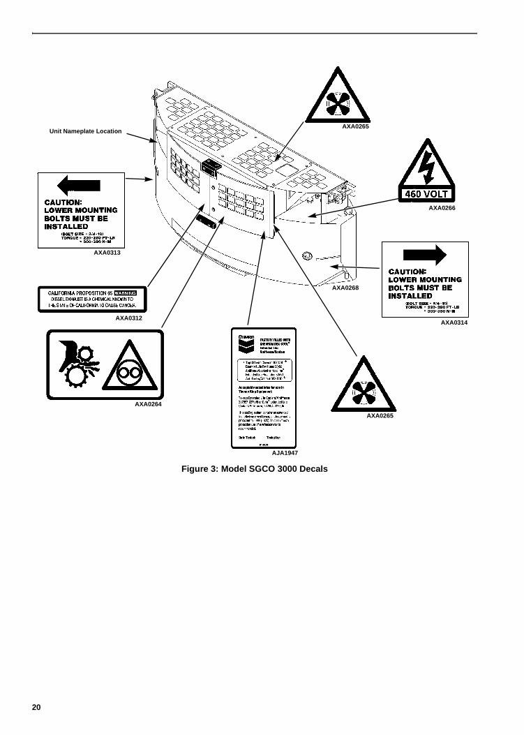
Figure 3: Model SGCO 3000 Decals
Unit Nameplate Location
AXA0312
AXA0264
AXA0265
AXA0265
AXA0313
AXA0314
AXA0266
AXA0268
AJA1947
20

Service Guide
This table is for Models SGSM 3000, SGCM 3000 and SGCO 3000.
1Inspect/service every 250 operating hours in extreme (dirt yard) operating conditions.2More frequent intervals may be necessary in extreme operating conditions.
PreTrip
Every 2501
Hours
10 Months +/- 2 Months
Inspect/Service These Items
Electrical
• Perform a controller Pretrip (PTI) check.
• • • Inspect battery terminals and electrolyte level.
• Inspect wire harness for damaged wires or connections.
Engine
• Check fuel supply and fill.
• • • Check engine oil level and fill as needed.
• • • Check engine coolant level. (CAUTION: Do not remove radiator cap while coolant is hot.)
• • • Inspect belt for condition and proper tension.
• • • Check engine oil pressure hot, on high speed. Minimum 276 kPa, 2.76 bar, 40 psi.
• • • Listen for unusual noises, vibrations, etc.
• • • Inspect/clean fuel transfer pump inlet strainer.
• •Check air cleaner restriction indicator (change filter when indicator reaches 25 in.). Replace air cleaner element at 3,000 hours or two years (whichever occurs first) if indicator has not reached 25 in.
• • Drain water from fuel tank and check vent. Clean fuel strainer in transfer pump inlet.
• • Check and adjust engine speed. See “Engine Speed Adjustment” on pages 101 and 102.
• Change engine oil2 (hot) and oil filter.
• Change engine oil (hot) and oil filter.2
• Change fuel filter/water separator.2
• Check condition of engine mounts.
— Change ELC (red) engine coolant every 5 years or 12,000 hours. Maintain antifreeze protection at -34 C (-30 F).
— Replace fuel return lines between fuel injection nozzles every 10,000 hours.
Structural
• • • Visually inspect unit for fluid leaks (coolant and oil).
• • • Visually inspect unit for damaged, loose or broken parts.
21

Service Guide
22

Specifications
* SG+ controller uses a sensor to provide engine high coolant temperature protection.
EngineDiesel Engine Model TK486V (Tier 2)
Fuel Type No. 2 Diesel fuel under normal conditions No. 1 Diesel fuel is acceptable cold weather fuel
Oil Capacity Crankcase: Crankcase and Oil Filter:
12.3 litre (13 qt) 13.3 litre (14 qt) Fill to full mark on dipstick
Oil Type:
Classification:
Multi-grade Petroleum Oil (Standard)Synthetic Oil (Optional) after first 500 hoursAPI Type CI-4 or betterACEA Type E3 or better
Oil Viscosity: -30 C to +0 C (-22 F to +32 F): -25 C to +30 C (-13 F to +86 F): -25 C to +40 C (-13 F to +104 F): -15 C to +50 C (+5 F to +122 F):
SAE 5W-30 SAE 10W-30 SAE 10W-40 SAE 15W-40
Engine Oil Pressure 120 to 320 kPa (1.2 to 3.2 bar) (18 to 47psi)
Engine RPM: No Load: 1890 ± 10 RPM (High Speed)
1550 + 10/-0 RPM (Low Speed EcoPower Option only)
Valve Clearance 0.15 to 0.25 mm (0.006 to 0.010 in.)
Valve Setting Temperature 21 C (70 F) (Room Temperature)
Low Oil Pressure Switch (Normally Closed) 117 ± 21 kPa (1.17 ± 0.21 bar) (17 ± 3 psi)
High Coolant Temperature Switch* Sensor*
Engine Thermostat 71 C (160 F)
Coolant System Capacity 9.5 liter (10 qt) with overflow tank
Engine Coolant Type Texaco ELC (Extended Life Coolant) or equivalent: ELC red coolant, 50/50 antifreeze and water mixture, not to exceed 60/40
Radiator Cap Pressure 90 kPa (0.90 bar) (13 psi)
Fan/Water Pump Belt Tension New or Field Reset: 15 to 35 tension number on belt tension gauge,
TK P/N 204-427; or 19 to 25 mm (0.75 to 1.0 in.) deflection with 3 to 4 Kg (6 to 9 lb) of force
GeneratorType 460/230 Vac, 3 Phase, 60 Hz
Output Power 15 kw
Kilovolt-Amperes 18.75 kVA
RPM 1800 RPM
23

Specifications
Electrical Control SystemControls SG+ microprocessor controller
Voltage 12.5 Vdc (nominal)
Battery 12 volts, group C31, 950 Cold Cranking Amps at -18 C (0 F)
Fuse SI1 30 Amp
Fuse SI2 30 Amp
Fuse SI3 10 Amp
Electrical ComponentsNOTE: Disconnect components from unit circuit to check resistance.
Current Draw (Amperes) at 12.5 Vdc Resistance (Ohms)
Air Heater 89 0.14
Fuel Solenoid:
Pull-in
Hold-in
35 to 45
0.5 to 1.0
0.2 to 0.3
24 to 29
Speed Solenoid (EcoPower Option only) 2.9 4.3
Starter Motor 400 (cranking) 140 (bench test)
Controller Default SettingsSetting – Menu Location Default Setting
Tank Size – Commands/System Setup 125
Date/Time – Commands/System Setup Software Date
ID Number – Commands/System Setup 00000000
C/F Mode – Misc. Functions F
LOP (Low Oil Pressure) Restart – Configuration Off
DEL (Delayed) Coldstart – Configuration On
HM1 (Hour Meter 1) Threshold – Configuration 0
HM2 (Hour Meter 2) Threshold – Configuration 0
ENG (Engine) Off Hours – Configuration 0
Factory Reset – Configuration Off
APU Connected – Configuration Off
Output Voltage – Configuration 460
Fuel Sensor – Configuration Off
Fuel Level – Configuration 0
Crank Restarts – Configuration 3
Telematic – Configuration Off
NOTE: The controller returns the Date/Time to the default setting when the battery is disconnected.
24

Specifications
Physical SpecificationsWeight (net): SGSM 3000 678 Kg (1495 lbs) including oil, coolant, battery and
284 liter (75 gal.) fuel tank (excluding fuel)
Unit Dimensions
AXA0269
25
Specifications
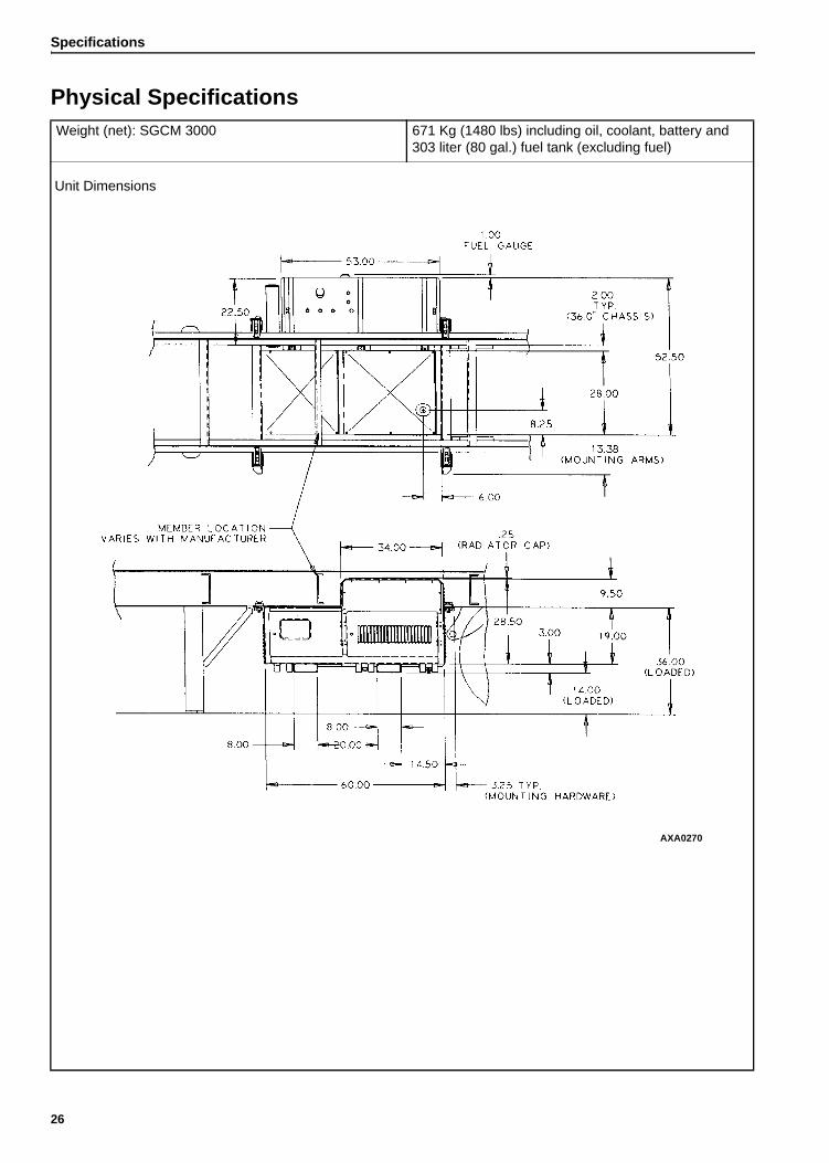
Physical SpecificationsWeight (net): SGCM 3000 671 Kg (1480 lbs) including oil, coolant, battery and
303 liter (80 gal.) fuel tank (excluding fuel)
Unit Dimensions
AXA0270
26

Specifications
Physical SpecificationsWeight (net): SGCO 3000 818 Kg (1804 lbs) including oil, coolant, battery and
473 liter (125 gal.) fuel tank (excluding fuel)
Unit Dimensions:
AXA0271
27

Specifications
Metric Hardware Torque Charts
*HH = Hex Head, CL = Class.
Bolt Type and Class*
Bolt Size
M6 M8 M10 M12
N.m (Ft.-lb.) N.m (Ft.-lb.) N.m (Ft.-lb.) N.m (Ft.-lb.)
HH – CL 5.8 6-9 (4-7) 12-16 (9-12) 27-34 (20-25) 48-61 (35-40)
HH – CL 8.8 10-13 (7-10) 20-27 (15-20) 41-47 (30-35) 75-88 (55-65)
HH – CL 10.9 14-17 (10-13) 27-34 (20-25) 54-68 (40-50) 102-122 (75-90)
HH – CL 12.9 17-21 (12-16) 41-47 (30-35) 68-81 (50-60) 122-149 (90-110)
HH – SS (2) 10-13 (7-10) 20-27 (15-20) 41-47 (30-35) 75-88 (55-65)
Bolt Type and Class*
Bolt Size
M14 M16 M18 M22
N.m (Ft.-lb.) N.m (Ft.-lb.) N.m (Ft.-lb.) N.m (Ft.-lb.)
HH – CL 5.8 75-88 (55-65) 115-135 (85-100) 177-216 (130-160) 339-406 (250-300)
HH – CL 8.8 115-135 (85-100) 177-216 (130-160) 271-339 (200-250) 475-610 (350-450)
HH – CL 10.9 136-176 (100-130) 224-298 (180-220) 393-474 (290-350) 678-813 (500-600)
HH – CL 12.9 177-216 (130-160) 285-352 (210-260) 448-542 (330-400) 881-1016 (650-750)
HH – SS (2) 115-135 (85-100) 177-216 (130-160) 271-339 (200-250) 475-610 (350-450)
28

Unit Description, Features & Options
General DescriptionThermo King generator sets (clip-on, center mount and side-mount) are self-contained fully-automatic, diesel powered units. The generator sets supply 230 or 460 Vac electrical power for container refrigeration units. Enclosed within the unit frame are the engine, dual voltage alternator, generator battery compartment, battery charging regulator and control panel.
An exclusive TK486V (EPA Tier 2) direct injection diesel engine drives a brushless generator to produce 15 KW of output power at 49 C (120 F) ambient temperature. A weatherproof box fastened inside the unit contains the unit controls.
Each unit features a welded, heavy-gauge steel frame with special sea-going finish; non-corrosive fittings, all stainless steel external hardware, copper tube aluminum fin radiator, and poly-vinyl coating on the engine and generator.
Fuel tanks are provided as an integral part of each unit. Fuel capacities are: 473 liter (125 gal.) on SGCO clip-on models; 303 liter (80 gal.) on SGCM center mount models; and 284 liter (75 gal.) on SGSM side mount models.
The alternator is a brushless, rotating field ac generator. A rectified exciter armature output provides dc power for the field. The exciter field obtains its power from the full wave rectified output of the main generator. The alternator supplies 230 or 460 Vac, 3 phase, 4 wire, 60 Hz power at 1800 RPM.
This equipment develops normal output voltages (below 600 volts) whenever the engine is running. All output voltages normally reach 460 volts. Under malfunction conditions, 575 volts may be produced. Any electric potential more than 50 volts is hazardous. Exercise caution and discretion in the operation and maintenance of the equipment.
Figure 4: SGSM 3000 Side Mount Generator
Figure 5: SGCM 3000 Center Mount Generator
Figure 6: SGCO 3000 Clip On Generator
CAUTION: DO NOT attempt to operate or maintain the generator until you have completely familiarized yourself with the equipment.
AXA0272
AXA0273
AXA0274
29

Unit Description, Features & Options
EMI 3000 PackageThese units are equipped with an EMI 3000 Extended Maintenance Interval package. The EMI 3000 package will result in lower total unit life cycle cost, because maintenance intervals have an important impact on unit operating costs.
The EMI 3000 package includes:
• 5 Year or 12,000 Hour Extended Life Coolant (ELC)
• EMI 3000 Dual Element Oil Filter, P/N 11-9182 (identified by black and gold colors)
• EMI 3000 API Rating CI-4 Mineral Oil
• EMI 3000 Fuel Filter, P/N 11-9342 (identified by black and gold colors)
EMI 3000 equipped units are identified by a “ELC” decal tag on the coolant expansion tank, and gold and black colored oil and fuel filters. The EMI 3000 package allows standard genset maintenance intervals to be extended to 3000 hours. However, please note that units equipped with the EMI 3000 package still require regular inspection in accordance with Thermo King pretrip inspection and maintenance recommendations (see the Service Guide chapter in this manual).
SG+ Microprocessor ControllerThe SG+ Microprocessor controller controls and monitors unit operation, records system faults and performs an automatic pre-trip check. The controller monitors all unit protection shutdown functions and the exciter system.The controller shuts down unit operation due to low engine oil pressure, low engine oil level, high coolant temperature, fuel relay feedback failure, or alternator overload. The module also delays excitation power supply for 15 seconds after unit start-up or until the engine water temperature reaches 32 C (90 F).
The SG+ Microprocessor controller is designed with the capability to have the software flash loaded.
Figure 7: SG+ Controller Display
Unit InstrumentsINDICATOR LEDs.
a. POWER LED: A green Power LED lights up while the Unit On/Off Switch is in the ON position. It is located on the controller display.
b. ALARM LED: A red Alarm LED illuminates when a shutdown condition has occurred. It is located on the controller display.
FUEL GAUGE. A gauge mounted in the fuel tank indicates the level of diesel fuel in the tank.
30
Unit Description, Features & Options
Unit Protection Devices
Low Oil Pressure Switch: Engine oil pressure should rise immediately on starting. The controller will stop the engine if oil pressure drops below 117 ± 21 kPa, (1.17 ± 0.21 bar), (17 ± 3 psig) for more than 30 seconds, and the oil level drops below 8 qt (7.6 litres) (Also see oil level sensor below). The controller then records an alarm.
Oil Level Sensor: An oil level switch closes if the oil level drops below 8 qts. (7.6 liters) and the oil pressure drops below 117 ± 21 kPa (Also see low oil pressure switch above). The controller will stop the engine if the switch stays closed for more than 30 seconds. The controller then records an alarm.
Water Temperature Sensor: The controller will stop the engine if the engine coolant temperature rises to 107 C (225 F) for more than 30 seconds. The controller also records an alarm. The unit will restart when the coolant temperature drops to 88 C (190 F).
Dual Voltage OptionA power cable and receptacle wired for 230 Vac or 460 Vac is supplied as standard equipment with each generator. SGCM center mount models can be wired for dual receptacles: 230 Vac or 460 Vac.
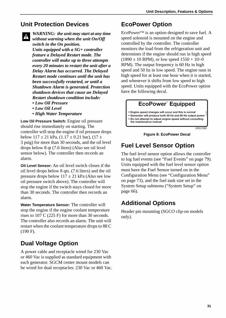
EcoPower OptionEcoPowerTM is an option designed to save fuel. A speed solenoid is mounted on the engine and controlled by the controller. The controller monitors the load from the refrigeration unit and determines if the engine should run in high speed (1890 ± 10 RPM), or low speed 1550 + 10/-0 RPM). The output frequency is 60 Hz in high speed and 50 hz in low speed. The engine runs in high speed for at least one hour when it is started, and whenever it shifts from low speed to high speed. Units equipped with the EcoPower option have the following decal.
Figure 8: EcoPower Decal
Fuel Level Sensor OptionThe fuel level sensor option allows the controller to log fuel events (see “Fuel Events” on page 79). Units equipped with the fuel level sensor option must have the Fuel Sensor turned on in the Configuration Menu (see “Configuration Menu” on page 73), and the fuel tank size set in the System Setup submenu (“System Setup” on page 66).
Additional OptionsHeader pin mounting (SGCO clip-on models only).
WARNING: the unit may start at any time without warning when the unit On/Off switch in the On position.Units equipped with a SG+ controller feature a Delayed Restart mode. The controller will make up to three attempts every 20 minutes to restart the unit after a Delay Alarm has occurred. The Delayed Restart mode continues until the unit has been successfully restarted, or until a Shutdown Alarm is generated. Protection shutdown devices that cause an Delayed Restart shutdown condition include:• Low Oil Pressure• Low Oil Level• High Water Temperature 92
-638
4
ARA1066
31

Unit Description, Features & Options
1. Unit Mounting Arms 6. Unit Nameplate Location
2. Fuel Tank 7. Fuel Tank Fill Neck and Cap
3. Control Box Cover 8. Coolant Expansion Tank Location
4. Alternator and Control Box Compartment Access Door
9. 460 or 230 Vac Power Receptacle Location
5. Engine Compartment Access Door
Figure 9: SGSM 3000 — Unit Front View
1
2
34
5
6
7
8
9
AXA0272
32

Unit Description, Features & Options
1. Fuel Tank 6. Control Box Cover
2. Fuel Tank Fill Neck and Cap 7. Engine Compartment Access Door
3. Unit Mounting Arms 8. Coolant Expansion Tank Location
4. Unit Nameplate Location 9. 460 or 230 Vac Power Receptacle Location
5. Alternator and Control Box Compartment Access Door
10. Radiator Location
Figure 10: SGCM 3000 — Unit Front View
1
2
3
4
5
6
7
8
10
AXA0273
9
33

Unit Description, Features & Options
1
2
3
4
67
8
9
10
11
12
AXA0274
5
1. Battery 7. Lower Mounting Screw and Washer (each side)
2. Unit Nameplate Location 8. Fuel Gauge (each side)
3. Fuel Tank 9. Control Box Location
4. Alternator and Engine Compartment Access Doors
10. Fuel Tank Fill Neck and Cap (each side)
5. Coolant Expansion Tank Location 11. Upper Unit Mounting Clamps (Corner Clamp Equipped Units Only)
6. 460 or 230 Vac Power Receptacle Location
12. Header Pin Mounting Flange (Header Pin Equipped Units Only)
Figure 11: SGCO 3000 — Unit Front View
34

Unit Description, Features & Options
1
2
3
4
5
6
78
9
10
11
12
13
1. Air Inlet Adapter 8. Oil Fill and Dipstick
2. Alternator 9. Oil Level Sensor
3. Starter 10. Oil Drain
4. Timing Mark Location 11. Engine Speed Adjustment Screw
5. Flywheel Sensor 12. Water Pump Pulley
6. Oil Filter 13. Water Temperature Sensor
7. Low Oil Pressure Switch
Figure 12: Powerpack (All Models) — Unit Front View
35

Unit Description, Features & Options
36

Controller Description
SG+ Controller DescriptionThe SG+ controller is a two-piece, self contained microprocessor for diesel generator sets. The SG+ display is mounted on the control box cover. The SG+ microprocessor is mounted inside the control box (see Figure 14 on page 38). Two external relays, the Start Relay and the Preheat Relay, are also mounted inside the control box near the microprocessor.
This system automatically controls generator operation by providing:
• Automatic unit preheat and engine startup during initial startup or delayed restart
• Variable air heater preheat time
• Automatic Pretrip Test capability
• Delayed alternator excitation for 15 seconds or until engine coolant temperature increases to 32 C (90 F)
• Unit shutdown protection for the engine and alternator. The controller stops the unit due to low engine oil pressure, low engine oil level, high coolant temperature, fuel relay feedback failure, or alternator overload.
• Automatic unit restart 20 minutes after unit shutdown due to an unknown condition, high engine water temperature, engine failure to start, fuel relay feedback failure, check fuel alarm, or alternator overload (also low engine oil pressure if enabled).
Figure 13: SG+ Controller Display
37

Controller Description
1. J6 Connector – To AC Circuits
2. Fuse SI1 – 30 Amp Protects 8D and 8DP Circuits
3. Fuse SI2 – 30 Amp Protects Battery Charger Output Circuit
4. 2A Circuit Connection
5. CH Circuit Connection
6. GND Circuit Connection
7. Serial Port – For Flash Loading Software
8. J2 Connector – To SG+ Controller Display
9. 2C Circuit Connection
10. 8 Circuit Connection
11. Fuse SI3 – 10 Amp Protects Microprocessor Power Input Circuit
12. J4 Connector – To External Relay Circuits
13. RL1 – Fuel Pull Relay
14. RL2 – Fuel Hold Relay
15 J1 Connector – To Sensor and Fuel Solenoid Circuits
Figure 14: SG+ Microprocessor
4
7
1 2 3 5 6
8
9
10
11
12
14
13
15
38

Controller Description
Controller OverviewDisplay: A vacuum lucent display on the front panel shows operating information including output voltage, current test state during a Pretrip test and the controller menu. Normally it shows the Output Voltage (this is called the Standard Display). It will be blank when the unit On/Off switch is OFF.
Keypad: Contains the following six keys.
Escape Key: Press this key to escape a new setting or jump to the parent menu.
Up Key: Press this key to scroll UP through the menu display, or increase the value of a setting.
Down Key: Press this key to scroll DOWN through the menu display, or decrease the value of a setting.
Enter Key: Press this key to enter or execute controller menu tasks or commands.
Alarm Key: Press this key to go directly to the Alarm List Menu and view the alarm information in the display.
Language Key: Press this key to change the language used on the display. English and Spanish are the languages that are currently available.
Alarm LED: Flashes when the controller has detected an alarm condition. It is off when there are no alarms.
Power LED: Lights up while the Unit On/Off Switch is in the ON position. It is off when the Unit On/Off Switch is in the OFF position.
Unit On/Off Switch: In the ON position, the electrical control system energizes for unit operation. In the OFF position, the electrical control system including the fuel solenoid de-energizes to stop the engine. The unit will not operate.
Download Port: Is used to download the event logger and flash load new software.
1. Display
2. Down Key
3. Enter Key
4. Keypad
5. Language Key
6. Power LED
7. Unit On/Off Switch
8. Download Port
9. Alarm LED
10. Alarm Key
11. Escape Key
12. Up Key
Figure 15: Control Box Cover
1
2
3
4
5
6
7
9
10
11
12
8
39

Controller Description
Miscellaneous Features
• Internal self-checking/diagnostic capability
• Pretrip test capability (see “PTI” on page 63)
• Hourmeter: The controller has a built-in run hourmeter that can be accessed through the Timers/Counters Submenu under the Misc. Functions Menu.
• The application software version is displayed by selecting the Program Version Submenu under the Misc. Functions Menu.
• Display menus: The SG+ controller contains extensive display menus that can be navigated via the keypad. The display menus are organized into seven Main Menus: Data Menu, Alarm List Menu, Warning List Menu, Commands Menu, Misc. Functions Menu, Configuration Menu, and Event Log Menu.
• Microprocessor Inputs:
• Engine Oil Pressure
• Alternator Voltage
• Battery Voltage
• Water (Engine Coolant) Temperature
• Air Filter Switch
• Coolant Level Sensor
• Engine Oil Pressure Switch
• Engine Oil Level Sensor
• Air Heater (Preheat) Feedback
• Fuel Pull Relay Feedback
• Fuel Hold Relay Feedback
• Excitation Feedback
• Flywheel Sensor
• Microprocessor Outputs:
• Start Relay
• Preheat Relay
• Fuel Pull Relay
• Fuel Hold Relay
• Speed Solenoid Relay (EcoPower Option only)
• On Light
• Alarm Light.
40

Navigating the Controller Menus
Controller Display MenusThe SG+ controller contains extensive display menus that can be navigated via the keypad. The display menus are organized into the following menus (or groups) in the Main Menu:
• Data Menu
• Alarm List Menu
• Message List Menu
• Commands Menu
• Misc. Functions Menu
• Configuration Menu
• Event Log Menu
The display also has some displays in addition to the Main Menus.
• Standard Display
• Pause Mode Display
Each menu listed above will be described later in this chapter.
An overview of the menu structure is shown in Figure 17 on page 42.
A complete listing of the controller menus is located on the 11 x 17 in. fold outs in the Diagrams section in the back of the manual (see last two pages in the manual). It is designed to be folded out so you can continuously view it as you are learning how to navigate the SG+ Controller Menus. It is recommended to fold this flow diagram out and leave it folded out until you become familiar with the controller menus.
Navigating Controller MenusMoving through the menus and their submenus and entering commands requires the use of the following keys:
Escape Key: Press the ESCAPE key to escape a new setting or jump to the parent menu.
Up Key: Press the UP key each time you want to scroll up to view another item in a menu (or submenu), or increase the value of a setting.
Down Key: Press the DOWN key each time you want to scroll down to view another item in a menu (or submenu), or decrease the value of a setting.
Enter Key: Press the ENTER key each time you want to enter or execute controller menu tasks or commands.
Alarm Key: Press the ALARM key to go directly to the Alarm List Menu and view the alarm information in the display.
Language Key: Press the LANGUAGE key to change the language used on the display.
Figure 16: Controller Display
1. Down Key
2. Enter Key
3. Language Key
4. Alarm Key
5. Escape Key
6. Up Key
1
2
34
5
6
41
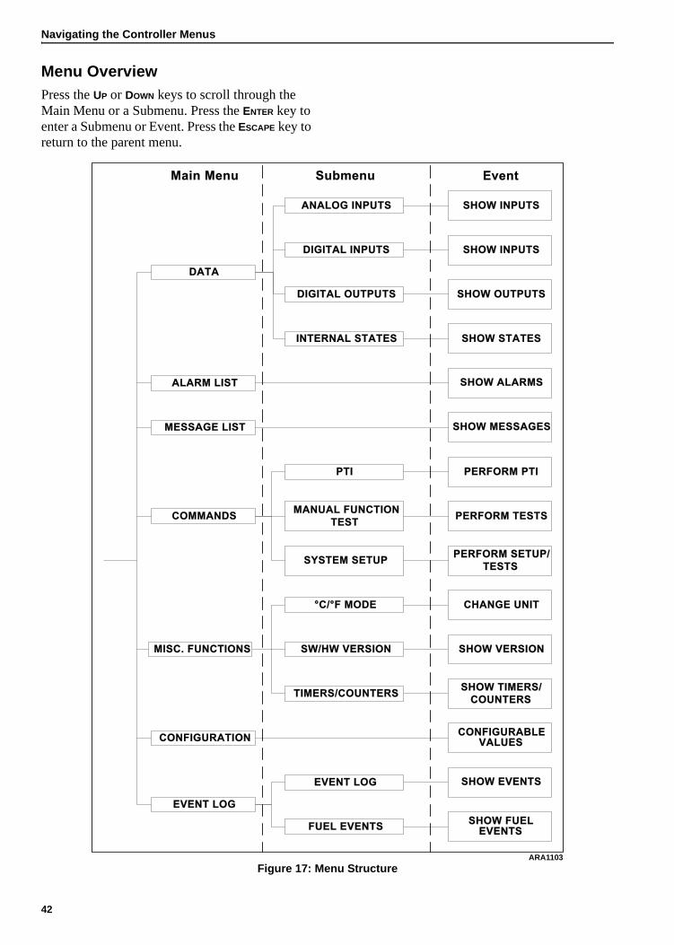
Navigating the Controller Menus
Menu OverviewPress the UP or DOWN keys to scroll through the Main Menu or a Submenu. Press the ENTER key to enter a Submenu or Event. Press the ESCAPE key to return to the parent menu.
Figure 17: Menu Structure
COMMANDS
MESSAGE LIST
ALARM LIST
DATA
ANALOG INPUTS
DIGITAL INPUTS
DIGITAL OUTPUTS
INTERNAL STATES
PTI
MANUAL FUNCTION
TEST
SHOW INPUTS
SHOW INPUTS
SHOW OUTPUTS
SHOW STATES
PERFORM PTI
PERFORM TESTS
SHOW ALARMS
SHOW MESSAGES
EventSubmenuMain Menu
SYSTEM SETUPPERFORM SETUP/
TESTS
EVENT LOG
CONFIGURATION
MISC. FUNCTIONS
°C/°F MODE
SW/HW VERSION
TIMERS/COUNTERS
CHANGE UNIT
SHOW VERSION
SHOW TIMERS/
COUNTERS
SHOW EVENTS
CONFIGURABLE
VALUES
EVENT LOG
SHOW FUEL
EVENTSFUEL EVENTS
ARA1103
42

Navigating the Controller Menus
Data MenuThe Data Menu contains the following submenus. See “Data Menu” on page 50 for more information.
• Analog Inputs, which displays unit operating information from analog inputs such as oil pressure and output voltage. See “Analog Inputs” on page 51 for more information.
• Digital Inputs, which displays unit operating information from digital inputs such as the oil level switch and feedback from the fuel solenoids. See “Digital Inputs” on page 52 for more information.
• Digital Outputs, which displays unit operating information from digital outputs such as the start relay and the preheat relay. See “Digital Outputs” on page 53 for more information.
• Internal States, which displays unit operating information such as the status of components, if the unit is running, and the engine RPM. See “Internal States” on page 54 for more information.
Alarm List MenuThe Alarm List Menu shows a list of the alarms recorded in the controller memory. See “Alarm List Menu” on page 55 for more information.
Message List MenuThe Message List Menu shows a list of the messages recorded in the controller memory. See “Message List Menu” on page 58 for more information.
Commands MenuThe Commands Menu contains the following submenus:
• PTI, which is the Pretrip Inspection Test. The PTI is a functional test of the unit. See “PTI” on page 63 for more information.
• Manual Function Test, which is used to test some components such as the display and relays. See “Manual Function Test” on page 64 for more information.
• System Setup, which is used to check the engine speed, energize and de-energize the Speed Solenoid, set the unit fuel tank size, set the date and time, and set an ID number to identify the unit. See “System Setup” on page 66 for more information.
Misc. Functions MenuThe Misc. Functions Menu contains the following submenus:
• C/F Mode, which is used to select whether Celsius or Fahrenheit units are used to display temperature readings. See “C/F Mode” on page 70 for more information.
• SW/HW Version, which displays information about the controller software and hardware. See “SW/HW Version” on page 71 for more information.
• Timers/Counters, which displays information about the hourmeters and restart counters. See “Timers/Counters” on page 72 for more information.
Configuration MenuThe Configuration Menu is used to configure some of the controller functions such as low oil pressure restart and hourmeter thresholds. See “Configuration Menu” on page 73 for more information.
Event Log MenuThe Event Log Menu contains the following submenus:
• Event Log, which shows a list of events, warnings, and alarms recorded in the controller memory. See “Event Log” on page 78 for more information.
• Fuel Events, which shows a list of fuel events recorded in the controller memory. See “Fuel Events” on page 79 for more information.
43

Navigating the Controller Menus
Standard DisplayThe Standard Display shows the output voltage. It appears approximately one minute after the last key is pressed while the unit is running. The Standard Display floats within the display to prevent burn in.
Press the ENTER key or the ESCAPE key at the Standard Display to enter the Main Menu.
Figure 18: Standard Display and Main Menu
Pause Mode Displays
A Pause mode display appears when normal unit operation has been interrupted because of a warning or alarm. The display will show the cause and controller action. For example, the following display appears if the engine fails to start.
Figure 19: Typical Pause Mode Display
DATA \
ALARM LIST
MESSAGE LIST
COMMANDS
MISC. FUNCTIONS
CONFIGURATION
EVENT LOG
OUTPUT 460 V
Standard Display
Main Menu
WARNING: The AC alternator output or engine may start at any time without notice when the unit is in a PAUSE mode.
ENGINE FAILED TO START
RESTART IN 20 MIN.
44

Operating Instructions
Pretrip InspectionThe pretrip inspection is an important part of the preventive maintenance program. It’s designed to head off operating problems and breakdowns before they happen.The Pretrip Inspection is not a substitute for a regularly scheduled maintenance.
Visual Inspection The following inspections should be made before loading the container or trailer:
Fuel: The diesel fuel supply must be sufficient to guarantee engine operation to the next check point.
Engine Oil: Engine oil level should be at the FULL mark. Never overfill. The dipstick is attached to the filler cap.
Coolant: Engine coolant must be above the ADD mark with antifreeze protection of -34 C (-30 F). Check and add coolant in the expansion tank.
Battery: Terminals must be clean. Electrolyte should be at the full mark.
Belt: The water pump belt must be in good condition and adjusted to proper tension.
Electrical: Electrical connections should be securely fastened. Check wires and terminals for corrosion, cracks or moisture. Repair or replace if necessary.
Structural: Visually inspect the unit for leaks, loose or broken parts and other damage. The radiator coil should be clean and free of debris. Clean if necessary. Use an air or water spray jet directed against the coil from the air discharge side.
Mounting Bolts: Check the mounting bolts on the unit and engine. Tighten if necessary.
WARNING: DO NOT remove the radiator cap from the radiator fill neck when the engine coolant is hot.
CAUTION: With both Extended Life Coolant (EMI 3000) and Conventional Coolant (non-EMI 3000) equipped units operating in the field, there are several important rules to remember:• Extended Life Coolant (ELC) is RED in color while conventional coolant is GREEN or BLUE-GREEN.• Do not add GREEN or BLUE-GREEN, conventional coolant to cooling systems using RED, Extended Life Coolant, except in an emergency. If conventional coolant is added to Extended Life Coolant, the coolant must be changed after 2 years instead of 5 years.
CAUTION: Air or water spray jet pressure should not be high enough to damage (bend) coil fins.
45

Operating Instructions
Starting the UnitGenerator sets are designed to provide power for a refrigeration unit. Before starting the generator set, make sure the refrigeration unit power cord is connected to the generator set electric power receptacle. To operate the refrigeration unit on standby power, disconnect the power cord from the generator set and plug it into the proper power supply.
1. Turn unit ON/OFF switch to On.
2. A series of displays called the Start Sequence appears on the display as follows:
a. YORK HMIREV 1.0
b. YORK HMISUM: XXX
c. MAIN MENUDATADELAY 11 (or 10, 09, 08, etc. to 01) The delay screen counts down from 11 to 01 while the controller performs some self checks.
d. MAIN MENUDATAINITThe controller energizes the air heater for preheat (if necessary). The preheat buzzer is energized during the preheat period. Preheat time ranges from 5 to 120 seconds, depending on the engine temperature. Preheat may continue until after the engine starts.
e. MAIN MENUDATAFUEL RELAY ONThe controller energizes the fuel relay.
f. MAIN MENUDATAALTERNATOR OFFThe controller verifies that the alternator output is off.
g. MAIN MENUDATAAIR HEATER ONThis display appears only if the controller determines that the engine coolant temperature is low enough to require that the air heater be energized.
h. MAIN MENUDATASTARTERThe engine begins cranking. The air heater and pre-heat buzzer may remain energized during the cranking period. The air heater may also remain energized for 30 seconds after the engine starts.
i. MAIN MENUDATARPM CHECKIf the engine RPM does not exceed 50 RPM during the first 4 seconds of cranking, or if the engine does not start after 30 seconds of cranking, the cranking cycle terminates.
j. MAIN MENUDATASPEED MEASThis display appears only on units equipped with the EcoPower option while the controller checks the low engine speed. The engine runs in low speed until the engine temperature reaches 32 C (90 F).
k. MAIN MENUDATADELAYED OUTPUTThis display appears while the controller delays energizing the alternator output for approximately 15 seconds. If the DEL COLDSTART feature in the Configuration Menu is set to ON, the alternator output remains off until the engine temperature reaches 32 C (90 F).
WARNING: With the unit On/Off switch in the “ON” position, the unit may start at any time without prior warning.
46

Operating Instructions
l. MAIN MENUDATASPEED MEASThis display appears only on units equipped with the EcoPower option while the controller checks the high engine speed. The engine switches to high speed when the engine temperature reaches 32 C (90 F).
m. MAIN MENUDATAVOLTAGE: This display shows the alternator output, indicating the alternator is functioning.
3. If the engine fails to start, place the unit switch in the OFF position. Determine and correct the cause of the starting failure. Then repeat the starting procedure.
After Start InspectionAfter the engine has started:
1. Listen for abnormal noises.
2. Check for any alarms or messages using the Alarm List Menu and the Message List Menu.
NOTE: The engine must operate for approximately 15 seconds before the exciter circuit and battery charging circuits are energized. When DEL COLDSTART feature in the Configuration Menu is set to ON, the alternator output remains off until the engine temperature increases to 32 C (90 F).
Functional InspectionTo properly perform a PTI (Pretrip Inspection Test) on units equipped with a SG+ controller, do not apply a load to the alternator.
1. Start the unit (see “Starting the Unit” on page 46).
2. Initiate an automatic PTI.
NOTE: Correct all existing alarm conditions and clear the alarm codes before performing a PTI.
a. Press the ENTER key or the ESCAPE key to enter the Main Menu, if necessary.
b. Press the UP or DOWN key to scroll up or down through the Main Menu to the Commands Menu.
c. Press the ENTER key to enter the Commands Menu.
d. The PTI submenu will be displayed.
e. Press the ENTER key to start the PTI.
3. The controller then performs the PTI. Observe the unit for proper operation and functions during the PTI. The display shows which component is being tested, and the test result (PASSED of FAILED).
a. The engine stops.
b. The controller beeps to test the buzzer.
c. A display test is performed. Watch the display to verify it is operating properly.
d. The oil level switch is tested.
e. The oil pressure switch is tested.
f. The coolant temperature sensor is tested.
g. The coolant level is tested.
h. Test speed solenoid relay, if detected.
i. The preheat relay is tested.
j. The fuel hold relay is tested.
k. The fuel pull relay is tested.
l. Test fuel level, if selected.
m. The start relay is tested.
n. The output voltage is tested.
o. The engine starts.
p. The display says “PASSED OUTPUT VOLTAGE TEST” if the output voltage is acceptable.
q. The oil pressure switch is tested.
r. Preheat is tested.
s. Test speed solenoid high and low, if detected.
CAUTION: Never use starting fluid.
47

Operating Instructions
NOTE: If a component fails its test, the PTI will stop at that point and display “FAILED - REBOOT”. Correct the problem and repeat the PTI by pressing the ENTER Key.
4. When the PTI is complete, the test ends automatically and the controller display shows “PTI PASSED (or FAILED) - REBOOT”. Turn the On/Off Switch Off and back On to reboot and return the unit to normal operation.
5. If an operating problem occurs during the PTI, view and correct any alarms or messages. Then acknowledge the alarms or messages and repeat the PTI.
NOTE: Acknowledge the alarms or messages ONLY after the alarm codes are documented and problems repaired.
48

Operating Instructions
Main MenuThe Main Menu contains the following menus:
• Data Menu
• Alarm List Menu
• Warning List Menu
• Commands Menu
• Misc. Functions Menu
• Configuration Menu
• Event Log Menu
To enter the Main Menu complete the following steps:
1. Place the On/Off switch in the “ON” position.
2. Press the ENTER key or the ESCAPE key to enter the Main Menu, if it is not displayed.
3. The Data Menu is typically the first menu displayed in the Main Menu.
• Press the ENTER key to enter the Data Menu.
• Press the UP or DOWN key to scroll up or down through the Main Menu.
Figure 20: Main Menu
MAIN MENUDATA
VOLTAGE: 460 V
MAIN MENUALARM LIST
VOLTAGE: 460 V
MAIN MENUMESSAGE LIST
VOLTAGE: 460 V
MAIN MENUCOMMANDS
VOLTAGE: 460 V
MAIN MENUMISC. FUNCTIONS
VOLTAGE: 460 V
MAIN MENUCONFIGURATION
VOLTAGE: 460 V
MAIN MENUEVENT LOG
VOLTAGE: 460 V
From "DATA" menu
To "DATA" menu
From "ALARM LIST" menu
To "ALARM LIST" menu
From "MESSAGE LIST" menu
To "MESSAGE LIST" menu
From "COMMANDS" menu
To "COMMANDS" menu
From "MISC. FUNCTIONS" menu
To "MISC. FUNCTIONS" menu
From "CONFIGURATION" menu
To "CONFIGURATION" menu
From "EVENT LOG" menu
To "EVENT LOG" menu
ARA981
49
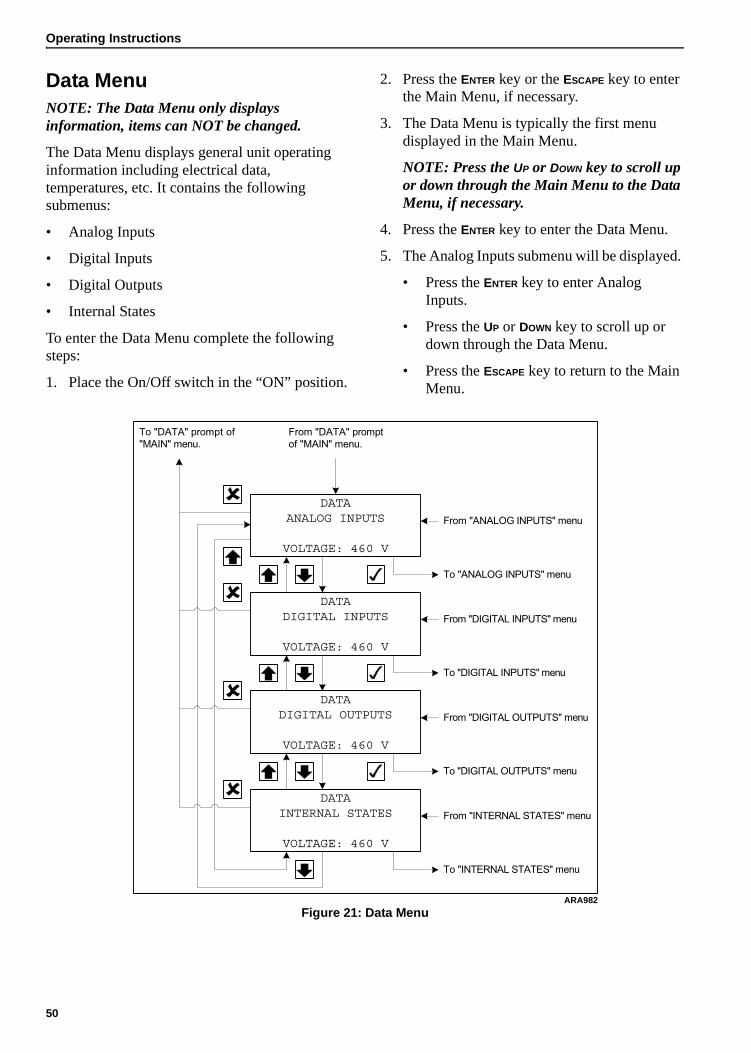
Operating Instructions
Data MenuNOTE: The Data Menu only displays information, items can NOT be changed.
The Data Menu displays general unit operating information including electrical data, temperatures, etc. It contains the following submenus:
• Analog Inputs
• Digital Inputs
• Digital Outputs
• Internal States
To enter the Data Menu complete the following steps:
1. Place the On/Off switch in the “ON” position.
2. Press the ENTER key or the ESCAPE key to enter the Main Menu, if necessary.
3. The Data Menu is typically the first menu displayed in the Main Menu.
NOTE: Press the UP or DOWN key to scroll up or down through the Main Menu to the Data Menu, if necessary.
4. Press the ENTER key to enter the Data Menu.
5. The Analog Inputs submenu will be displayed.
• Press the ENTER key to enter Analog Inputs.
• Press the UP or DOWN key to scroll up or down through the Data Menu.
• Press the ESCAPE key to return to the Main Menu.
Figure 21: Data Menu
DATAANALOG INPUTS
VOLTAGE: 460 V
DATADIGITAL INPUTS
VOLTAGE: 460 V
DATADIGITAL OUTPUTS
VOLTAGE: 460 V
DATAINTERNAL STATES
VOLTAGE: 460 V
To "DATA" prompt of
"MAIN" menu.
From "ANALOG INPUTS" menu
To "ANALOG INPUTS" menu
From "DIGITAL INPUTS" menu
To "DIGITAL INPUTS" menu
From "DIGITAL OUTPUTS" menu
To "DIGITAL OUTPUTS" menu
From "INTERNAL STATES" menu
To "INTERNAL STATES" menu
From "DATA" prompt
of "MAIN" menu.
ARA982
50

Operating Instructions
Analog InputsThe Analog Inputs display the following unit operating information:
• Voltage Meas. (AC Output Voltage)
• Bat. Voltage (Battery Voltage)
• Water Temp. (Engine Coolant Temperature)
• Running Freq. (AC Output Frequency)
To enter the Analog Inputs complete the following steps:
1. Place the On/Off switch in the “ON” position.
2. Press the ENTER key or the ESCAPE key to enter the Main Menu, if necessary.
3. The Data Menu is typically the first menu displayed in the Main Menu.
NOTE: Press the UP or DOWN key to scroll up or down through the Main Menu to the Data Menu, if necessary.
4. Press the ENTER key to enter the Data Menu.
5. The Analog Inputs submenu will be displayed.
6. Press the ENTER key to enter the Analog Inputs.
• Press the UP or DOWN key to scroll up or down through the Analog Inputs.
• Press the ESCAPE key to return to the Data Menu.
Figure 22: Analog Inputs
VOLTAGE MEAS. 460 VBAT. VOLTAGE 14.4 VWATER TEMP. 92ºCRUNNING FREQ. 60Hz
VOLTAGE MEAS. 460 VBAT. VOLTAGE 14.4 VWATER TEMP. 92ºCRUNNING FREQ. 60Hz
VOLTAGE MEAS. 460 VBAT. VOLTAGE 14.4 VWATER TEMP. 92ºCRUNNING FREQ. 60Hz
VOLTAGE MEAS. 460 VBAT. VOLTAGE 14.4 VWATER TEMP. 92ºCRUNNING FREQ. 60Hz
�������������� �
����������������������
���������������� �
����������������������
ARA770
51

Operating Instructions
Digital InputsThe Digital Inputs display the status of the following inputs:
• Air Filter Switch
• Coolant Level Low
• Oil Pressure Low
• Oil Level Low
• Spare 1
• Spare 2
• Starter FB (Feedback)
• Air Heater FB (Feedback)
• Fuel Pull FB (Feedback)
• Fuel Hold FB (Feedback)
• Speed Solenoid FB (Feedback)
• Spare 2 FB (Feedback)
To enter the Digital Inputs complete the following steps:
1. Place the On/Off switch in the “ON” position.
2. Press the ENTER key or the ESCAPE key to enter the Main Menu, if necessary.
3. The Data Menu is typically the first menu displayed in the Main Menu.
NOTE: Press the UP or DOWN key to scroll up or down through the Main Menu to the Data Menu, if necessary.
4. Press the ENTER key to enter the Data Menu.
5. Press the UP or DOWN key to scroll up or down through the Data Menu to the Digital Inputs submenu.
6. Press the ENTER key to enter the Digital Inputs.
• Press the UP or DOWN key to scroll up or down through the Digital Inputs.
• Press the ESCAPE key to return to the Data Menu.
Figure 23: Digital Inputs
AIR FILTER SWITCH OFFCOOLANT LEVEL LOW OFFOIL PRESSURE LOW OFFOIL LEVEL LOW OFF
To "DIGITAL INPUT" prompt
of "DATA" menu.
From "DIGITAL INPUT" prompt
of "DATA" menu.
AIR FILTER SWITCH OFFCOOLANT LEVEL LOW OFFOIL PRESSURE LOW OFFOIL LEVEL LOW OFF
AIR FILTER SWITCH OFFCOOLANT LEVEL LOW OFFOIL PRESSURE LOW OFFOIL LEVEL LOW OFF
AIR FILTER SWITCH OFFCOOLANT LEVEL LOW OFFOIL PRESSURE LOW OFFOIL LEVEL LOW OFF
4x4x
SPARE1 OFFSPARE2 OFFSTARTER FB OFFAIR HEATER FB OFF
FUEL PULL FB OFFFUEL HOLD FB ONSPEED SOLENIOD FB ONSPARE2 FB OFF
4x4x
ARA1068
52

Operating Instructions
Digital OutputsThe Digital Outputs display the status of the following outputs:
• Bat. Charger
• Start Relay
• Preheat Relay
• Fuel Relay Pull
• Fuel Relay Hold
• Speed Solenoid
To enter the Digital Outputs complete the following steps:
1. Place the On/Off switch in the “ON” position.
2. Press the ENTER key or the ESCAPE key to enter the Main Menu, if necessary.
3. The Data Menu is typically the first menu displayed in the Main Menu.
NOTE: Press the UP or DOWN key to scroll up or down through the Main Menu to the Data Menu, if necessary.
4. Press the ENTER key to enter the Data Menu.
5. Press the UP or DOWN key to scroll up or down through the Data Menu to the Digital Outputs submenu.
6. Press the ENTER key to enter the Digital Outputs.
• Press the UP or DOWN key to scroll up or down through the Digital Outputs.
• Press the ESCAPE key to return to the Data Menu.
Figure 24: Digital Outputs
BAT. CHARGER ONSTART RELAY OFFPREHEAT RELAY OFFFUEL RELAY PULL OFF
To "DIGITAL OUTPUT"
prompt of "DATA" menu.
From "DIGITAL OUTPUT"
prompt of "DATA" menu.
BAT. CHARGER ONSTART RELAY OFFPREHEAT RELAY OFFFUEL RELAY PULL OFF
BAT. CHARGER ONSTART RELAY OFFPREHEAT RELAY OFFFUEL RELAY PULL OFF
BAT. CHARGER ONSTART RELAY OFFPREHEAT RELAY OFFFUEL RELAY PULL OFF
START RELAY OFFPREHEAT RELAY OFFFUEL RELAY PULL OFFFUEL RELAY HOLD ON
PREHEAT RELAY OFFFUEL RELAY PULL OFFFUEL RELAY HOLD ONSPEED SOLENIOD ON
ARA1069
53

Operating Instructions
Internal StatesThe Internal States displays which of the following states the unit is in as it prepares to start, and after it starts or if it shuts down:
• INIT (Initiation Checks)
• Fuel Relay On
• Air Heater On
• Air Heater Off
• Restart 20 MI (Minutes)
• Running
• Shutdown
• HW Error
• Delay
• PTI
• RPM (Displayed Below the State)
To enter the Internal States complete the following steps:
1. Place the On/Off switch in the “ON” position.
2. Press the ENTER key or the ESCAPE key to enter the Main Menu, if necessary.
3. The Data Menu is typically the first menu displayed in the Main Menu.
NOTE: Press the UP or DOWN key to scroll up or down through the Main Menu to the Data Menu, if necessary.
4. Press the ENTER key to enter the Data Menu.
5. Press the UP or DOWN key to scroll up or down through the Data Menu to the Internal States submenu.
6. Press the ENTER key to enter the Internal States.
7. Press the ESCAPE key to return to the Data Menu.
Figure 25: Internal States
STATE: INITRPM: 1900
To "INTERNAL STATES"
prompt of "DATA" menu.
From "INTERNAL STATES"
prompt of "DATA" menu.
ARA729
54

Operating Instructions
Alarm List MenuThe Alarm List Menu displays alarms. Alarms are recorded in the controller memory to simplify unit diagnostic procedures. The alarms are listed in the reverse order of their occurrence. The Alarm LED flashes if a shutdown alarm is present. Enter the Alarm List Menu to view the and acknowledge the alarms.
Alarm TypesThere are two types of alarms:
Delayed Restart Alarm: Delayed restart alarms indicate the unit has stopped temporarily because of a problem or to prevent damage to the unit. The unit will attempt to restart in 20 minutes. The display will show information about the unit in the message screen and the time left to the restart attempt. A delayed restart alarm becomes a shutdown alarm after the third failed restart attempt in an hour.
Shutdown Alarm: The Alarm LED flashes and unit stops. Shutdown alarms indicate the unit has been stopped to prevent damage to the unit. The condition must be corrected before restarting the unit.
Displaying and Acknowledging AlarmsEnter the Alarm List Menu to view and acknowledge the alarms as follows:
1. Place the On/Off switch in the “ON” position.
2. Press the ALARM key to enter the Alarm List Menu directly. Or Enter the Alarm List Menu through the Main Menu as follows:
a. Press the ENTER key or the ESCAPE key to enter the Main Menu, if necessary.
b. Press the UP or DOWN key to scroll up or down through the Main Menu to the Alarm List Menu.
c. Press the ENTER key to enter the Alarm List Menu.
3. The Alarm List Menu will appear on the display. It shows the most recent alarm and the following information:
• The alarm code (101 through 109)
• The position of the alarm in the list of recorded alarms. For example, 1/2 means alarm one of two.
• The alarm text
• The alarm status (Active or Acknowledged).
4. Write down the alarm code and the alarm text.
5. Press the ENTER key to acknowledge the alarm. The Alarm LED will continue flashing until the active alarms (and messages) have been acknowledged.
6. Press the DOWN key to scroll down to the next alarm, if necessary.
7. Write down the alarm code and the alarm text.
8. Press the ENTER key to acknowledge the alarm.
9. Repeat steps 6 through 8 until all active alarms have been written down and acknowledged.
10. Press the ESCAPE key to return to the Main Menu.
Figure 26: Alarm List Menu
Alarm DiagnosisThe Alarm List on the following pages lists the alarms, their causes, and possible diagnosis.
102. 1/2WATER TEMPERATUREHIGHSTATUS: ACTIVE
To "ALARM LIST" prompt
of "MAIN" menu
From "ALARM LIST" prompt
of "MAIN" menu
Jump to previous alarm text
Jump to next alarm text
Acknowledges alarm
ARA753
55

Operating Instructions
Alarm List
Alarm Code and Text Alarm Type–Cause Diagnostics
101. WATER TEMPERATURE HIGH
Delayed Restart Alarm–Engine is running and water temperature is above 107 C (225 F) for 25 seconds.
• Engine then stops and then attempts to restart.
1. Check for cause of engine overheating:
• Check engine coolant level.
• Check water pump belt.
• Check radiator for airflow and coolant flow restrictions.
2. Check for faulty water temperature sensor.
102. FAILED TO CRANK
Delayed Restart Alarm–Engine failed to crank.
Becomes a Shutdown Alarm when number of restart attempts is greater than number of “Crank Restarts” set in Configuration Menu.
1. Check battery, battery cables, and starter.
2. Check 8S circuit.
3. Check Start Relay.
4. Check for seized engine or alternator.
103. FAILED TO START
Delayed Restart Alarm–Engine failed to crank.
Becomes a Shutdown Alarm when number of restart attempts is greater than number of “Crank Restarts” set in Configuration Menu.
1. Check fuel level.
2. Check fuel solenoid, fuel pump, and fuel system both electrically and mechanically.
3. In cold ambient temperatures check for fuel gelling.
4. Check for restricted air cleaner or air intake system.
5. Check intake air heater.
104. RL2 (FUEL H) FEEDBACK FAILURE
Shutdown Alarm–No feedback when relay is energized, or feedback when relay is not energized.
1. Check RL2 (Fuel Hold) relay.
2. Check 8D circuit.
105. RL1 (FUEL P) FEEDBACK FAILURE
Shutdown Alarm–No feedback when relay is energized, or feedback when relay is not energized.
1. Check RL1 (Fuel Pull) relay.
2. Check 8DP circuit.
106. RL5 (STARTER) FEEDBACK FAILURE
Shutdown Alarm–No feedback when relay is energized, or feedback when relay is not energized.
1. Check RL5 (Start) relay.
2. Check SR, PSR, and FSR circuits.
107. SYSTEM OVERLOADED
Delayed Restart Alarm– 1. Unplug load and attempt restart.
2. Check alternator field circuit.
3. Check alternator output circuit.
56

Operating Instructions
108. ENGINE NOT RUNNING REASON UNKNOWN
Delayed Restart Alarm–Input from Low Oil Pressure Switch is low (grounded) and RPM equals 0 when engine should be running.
• Engine will attempt to restart in 20 minutes.
1. Check fuel level.
2. Check fuel solenoid, fuel pump, and fuel system both electrically and mechanically.
3. In cold ambient temperatures check for fuel gelling.
4. Check for seized engine or alternator.
109.LOW OIL LEVEL
If low oil level and low oil pressure is present at the same time.
1. Check oil level.
2. Check Oil Level Switch.
3. Check circuits to Oil Level Switch.
4. Check oil pressure using the Analog Inputs submenu of the Data Menu.
5. Check Low Oil Pressure Switch.
6. Check OPS circuit.
Alarm List (Continued)
Alarm Code and Text Alarm Type–Cause Diagnostics
57

Operating Instructions
Message List MenuThe Message List Menu displays messages. Messages are recorded in the controller memory to simplify unit diagnostic procedures. The messages are listed in the reverse order of their occurrence. Enter the Message List Menu to view the and acknowledge the messages. Acknowledging a message clears it from the list.
NOTE: The unit will not start after being turned On until all active messages have been acknowledged. The display will indicate there are messages that have not been acknowledged.
Displaying and Acknowledging MessagesEnter the Message List Menu to view and acknowledge the messages as follows:
1. Place the On/Off switch in the “ON” position.
2. Press the ENTER key or the ESCAPE key to enter the Main Menu, if necessary.
3. Press the UP or DOWN key to scroll up or down through the Main Menu to the Message List Menu.
4. Press the ENTER key to enter the Message List Menu.
5. The Message List Menu will appear on the display. It shows the most recent message and the following information:
• The message code (101 through 127)
• The position of the message in the list of recorded messages. For example, 1/1 means message one of one.
• The message text
• The message status (Active or Acknowledged).
6. Write down the message code and the message text.
7. Press the ENTER key to acknowledge the message. The Alarm LED will continue flashing until the active messages (and alarms) have been acknowledged.
8. Press the DOWN key to scroll down to the next message, if necessary.
9. Write down the message code and the message text.
10. Press the ENTER key to acknowledge the message.
11. Repeat steps 8 through 10 until all active messages have been written down and acknowledged.
12. Press the ESCAPE key to return to the Main Menu.
13. The unit will then enter the Start Sequence and start the engine.
Figure 27: Message List Menu
Message DiagnosisThe Message List on the following pages lists the messages, their causes, and possible diagnosis.
101. 1/1WATER TEMPERATURESENSOR FAILURESTATUS: ACTIVE
To "MESSAGE LIST" prompt
of "MAIN" menu
From "MESSAGE LIST" prompt
of "MAIN" menu
Jump to previous warning text
Jump to next warning text
Acknowledges warning
ARA754
58

Operating Instructions
Message List
Message Code and Text Cause Diagnostics
101. BAT. VOLTAGE LOW
Battery Voltage is below 9 volts. 1. Check battery
2. Check battery cables.
102. DIGITAL INPUT FAILURE
Digital inputs have been changing once a second for the last 10 seconds.
This condition indicates noise on the line, a loose connection, or a bad sensor.
103. OUTPUT VOLTAGE < 180 V
The engine is running and the exciter field is energized, but the output voltage is below 360 volts for 30 seconds.
Check alternator for low output.
104. AIR FILTER BLOCKED
Not used.
105. COOLANT LEVEL LOW
Coolant Level Sensor indicates low coolant level for 30 seconds.
1. Check coolant level.
2. Check Coolant Level Sensor.
3. Check circuits to Coolant Level Sensor.
106. OUTPUT FREQUENCY LOW
Output frequency is below 45 Hz for 30 seconds (engine RPM below 1350).
Check and adjust engine speed.
107. OUTPUT FREQUENCY HIGH
Output frequency is above 70 Hz for 30 seconds (engine RPM above 2100).
Check and adjust engine speed.
108. LOW OIL LEVEL
Oil Level Switch indicates low oil level for 3 minutes.
1. Check oil level.
2. Check Oil Level Switch.
3. Check circuits to Oil Level Switch.
109. HOUR METER 1 HAS EXCEEDED THRESHOLD
Hour Meter 1 (HM1) has exceeded the threshold set in the Configuration Menu.
Acknowledge message to reset timer.
110. HOUR METER 2 HAS EXCEEDED THRESHOLD
Hour Meter 2 (HM2) has exceeded the threshold set in the Configuration Menu.
Acknowledge message to reset timer.
111. FUEL LEVEL LOW
Fuel Level is below “Fuel Level” set in Configuration Menu.
1. Check fuel level.
2. Check Fuel Level Sensor.
3. Check circuits to Fuel Level Sensor.
112. ENGINE RPM SENSOR FAILURE
Engine is running and input from Low Oil Pressure Switch is high (grounded), but RPM is below 800.
1. Check RPM Sensor.
2. Check circuits to RPM Sensor.
113. WATER TEMPERATURE SENSOR FAILURE
Water temperature sensor reading is below -40 C (-40 F) or above 130 C (266 F).
1. Check sensor circuits and wiring connections.
2. Check for faulty sensor.
114. LOW OIL PRESSURE
Engine is running and input from Low Oil Pressure Switch is low (grounded) for 60 seconds.
1. Check oil level.
2. Check oil pressure using the Analog Inputs submenu of the Data Menu.
3. Check Low Oil Pressure Switch.
4. Check OPS circuit.
59

Operating Instructions
115. RL6 (AIRHEAT) FEEDBACK FAILURE
No feedback when relay is energized, or feedback when relay is not energized.
1. Check RL6 (Preheat) relay.
2. Check PHR, PPHR, and FPHR circuits.
116.COUNTDOWN TIMER HAS EXPIRED
If hour counter exceeds user setup. 1. Acknowledge message and reset timer.
117. OIL PRESSURE HIGH WHILE ENG. IS NOT RUNNING
During PTI input from Low Oil Pressure Switch is high (not grounded) when the engine was not running.
1. Check Low Oil Pressure Switch.
2. Check OPS circuit.
118. OIL PRESSURE SWITCH FAILURE
Input from Low Oil Pressure Switch is high (not grounded) before engine starts.
1. Check Low Oil Pressure Switch.
2. Check OPS circuit.
119.WATER TEMPERATURE HIGH
If water temp. >107 C for 5 sec. - restarting.
1. Check water temperature sensor.
2. Check WTP/WTN circuit.
120. ENGINE FAILED TO CRANK
Engine failed to crank. 1. Check battery, battery cables, and starter.
2. Check 8S circuit.
3. Check Start Relay.
4. Check for seized engine or alternator.
121.ENGINE FAILED TO START
No oil pressure and did not reach 800 RPM - restarting.
1. Check fuel level.
2. Check fuel solenoid, fuel pump, and fuel system both electrically and mechanically.
3. In cold ambient temperatures check for fuel gelling.
4. Check for restricted air cleaner or air intake system.
5. Check intake air heater.
122.SYSTEM OVERLOADED
If output is short-circuited - restarting. 1. Unplug load and attempt restart.
2. Check alternator field circuit.
3. Check alternator output circuit.
123.ENGINE NOT RUNNING REASON UNKNOWN
If oil pressure low and no RPM, while running - restarting.
1. Check fuel level.
2. Check fuel solenoid, fuel pump, and fuel system both electrically and mechanically.
3. In cold ambient temperatures check for fuel gelling.
4. Check for seized engine or alternator.
124. NO LOAD RPM LESS THEN 1550
RPM less than 1550 after startup. 1. Check engine speed.
2. Check RPM sensor.
Message List (Continued)
Message Code and Text Cause Diagnostics
60

Operating Instructions
125. SPEED SOLENOID FEEDBACK FAILURE
No feedback when relay is energized, or feedback when relay is not energized.
1. Check RL3 (Speed [Throttle] Solenoid) relay.
2. Check 7D circuit.
126. FUEL LEVEL SENSOR OUT OF RANGE
Fuel level reading is above the maximum tank value.
1. Check fuel level sensor.
2. Check FPOS, FNEG, and FOUT circuits.
3. Check fuel tank size setting in System Setup submenu.
127.FUEL LEVEL DECREASED TO FAST
Fuel level reading decreased faster than normally expected.
NOTE: Must use password (0007) to clear this message.
1. Check for leak in fuel tank.
2. Check to see if fuel has been removed from fuel tank.
Message List (Continued)
Message Code and Text Cause Diagnostics
61

Operating Instructions
Commands MenuThe Commands Menu contains the following submenus that are used to test the operation or the unit and controller:
• PTI (Pretrip Inspection Test)
• Manual Function Test
• System Setup
To enter the Commands Menu complete the following steps:
1. Place the On/Off switch in the “ON” position.
2. Press the ENTER key or the ESCAPE key to enter the Main Menu, if necessary.
3. Press the UP or DOWN key to scroll up or down through the Main Menu to the Commands Menu.
4. Press the ENTER key to enter the Commands Menu.
5. The PTI submenu will be displayed.
• Press the ENTER key to start the PTI.
• Press the UP or DOWN key to scroll up or down through the Commands Menu.
• Press the ESCAPE key to return to the Main Menu.
Figure 28: Commands Menu
COMMANDSPTI
VOLTAGE: 460 V
To "COMMANDS"
prompt of "MAIN"
menu.
From "COMMANDS"
prompt of "MAIN"
menu.
From PTI test
To PTI test
COMMANDSMANUAL FUNCTION TEST
VOLTAGE: 460 V
To "MANUAL FUNCTION TEST" menu
From "MANUAL FUNCTION TEST" menu
COMMANDSSYSTEM SETUP
VOLTAGE: 460 V
To "SYSTEM SETUP" menu
From "SYSTEM SETUP" menu
ARA1070
62

Operating Instructions
PTIThe PTI (Pretrip Inspection Test) initiates a test of the unit’s electrical, engine, and alternator system components. To perform a PTI complete the following steps:
1. Place the On/Off switch in the “ON” position.
2. Press the ENTER key or the ESCAPE key to enter the Main Menu, if necessary.
3. Press the UP or DOWN key to scroll up or down through the Main Menu to the Commands Menu.
4. Press the ENTER key to enter the Commands Menu.
5. The PTI submenu will be displayed.
6. Press the ENTER key to start the PTI.
7. The controller then performs the PTI. Observe the unit for proper operation and functions during the PTI. The display shows which component is being tested, and the test result (PASSED of FAILED).
a. The engine stops.
b. The controller beeps to test the buzzer.
c. A display test is performed. Watch the display to verify it is operating properly.
d. The oil level switch is tested.
e. The oil pressure switch is tested.
f. The coolant temperature sensor is tested.
g. The coolant level is tested.
h. Test speed solenoid relay, if detected.
i. The preheat relay is tested.
j. The fuel hold relay is tested.
k. The fuel pull relay is tested.
l. Test fuel level, if selected.
m. The start relay is tested.
n. The output voltage is tested.
o. The engine starts.
p. The display says “PASSED OUTPUT VOLTAGE TEST” if the output voltage is acceptable.
q. The oil pressure switch is tested.
r. Preheat is tested.
s. Test speed solenoid high and low, if detected.
NOTE: If a component fails its test, the PTI will stop at that point and display “FAILED - REBOOT”. Correct the problem and repeat the PTI by pressing the ENTER Key.
8. When the PTI is complete, the test ends automatically and the controller display shows “PTI PASSED (or FAILED) - REBOOT”. Turn the On/Off Switch Off and back On to reboot and return the unit to normal operation.
9. If an operating problem occurs during the PTI, view and correct any alarms or messages. Then acknowledge the alarms or messages and repeat the PTI.
NOTE: Acknowledge the alarms or messages ONLY after the alarm codes are documented and problems repaired.
Figure 29: PTI Submenu
COMMANDSPTI
VOLTAGE: 460 V
To "COMMANDS" prompt of
"MAIN" menu
From "COMMANDS" prompt of
"MAIN" menu
To MANUAL FUNCTION TEST
To MANUAL FUNCTION TEST
Starts PTI
ARA984
63
Operating Instructions
Manual Function TestThe Manual Function Test submenu contains the following component tests:
• Display Test
• Preheat Relay Test
• Fuel Hold Relay Test
• Fuel Pull Relay Test
• Start Relay Test
• Force Speed (Energizes or de-energizes the speed solenoid to change the engine speed.)
The test result (PASSED of FAILED) is displayed after a test is performed. To enter the Manual Function Test complete the following steps:
1. Place the On/Off switch in the “ON” position.
2. Press the ENTER key or the ESCAPE key to enter the Main Menu, if necessary.
3. Press the UP or DOWN key to scroll up or down through the Main Menu to the Commands Menu.
4. Press the ENTER key to enter the Commands Menu.
5. The PTI submenu will be displayed.
6. Press the UP or DOWN key to scroll up or down through the Commands Menu to the Manual Function Test submenu.
7. Press the ENTER key to enter the Manual Function Test.
• The engine will stop if it is running.
• The Display Test is the first to appear. Press the ENTER key to perform the Display Test.
• Press the UP or DOWN key to scroll up or down through the Manual Function Test submenu. Press the ENTER key to perform the selected test.
• Press the ESCAPE key to return to the Commands Menu.
64

Operating Instructions
Figure 30: Manual Function Test Submenu
DISPLAY TESTPREHEAT RELAY TESTFUEL HOLD RELAY TESTFUEL PULL RELAY TEST
DISPLAY TESTPREHEAT RELAY TESTFUEL HOLD RELAY TESTFUEL PULL RELAY TEST
DISPLAY TESTPREHEAT RELAY TESTFUEL HOLD RELAY TESTFUEL PULL RELAY TEST
To "MANUAL FUNCTION TEST"
prompt of "COMMANDS" menu.
From "MANUAL FUNCTION TEST"
prompt of "COMMANDS" menu.
DISPLAY TESTPREHEAT RELAY TESTFUEL HOLD RELAY TESTFUEL PULL RELAY TEST
PERFORM
TEST
PERFORM
TEST
PERFORM
TEST
PERFORM
TEST
PREHEAT RELAY TESTFUEL HOLD RELAY TESTFUEL PULL RELAY TESTSTART RELAY TEST
PERFORM
TEST
FUEL HOLD RELAY TESTFUEL PULL RELAY TESTSTART RELAY TESTFORCE SPEED
CHANGE
SPEED
ARA1071
65

Operating Instructions
System SetupThe System Setup submenu contains the following:
• Current RPM, which is used to check the engine speed.
• Speed Solenoid (On/Off), which is used to energize and de-energize the speed solenoid when checking or adjusting the engine speeds.
• Tank Size (50/75/80/125), which is used to set the unit fuel tank size.
• Date/Time, which is used to set the date and time. See “Date/Time” on page 68 for information about setting the date and time.
• ID Number, which is used to set an ID number to identify the unit when downloading the event logger.
NOTE: The controller returns the Date/Time to the default setting when the battery is disconnected.
To enter the System Setup submenu complete the following steps:
1. Place the On/Off switch in the “ON” position.
2. Press the ENTER key or the ESCAPE key to enter the Main Menu, if necessary.
3. Press the UP or DOWN key to scroll up or down through the Main Menu to the Commands Menu.
4. Press the ENTER key to enter the Commands Menu.
5. The PTI submenu will be displayed.
6. Press the UP or DOWN key to scroll up or down through the Commands Menu to the System Setup submenu.
7. Press the ENTER key to enter the System Setup submenu.
8. Press the UP or DOWN key to scroll up or down through the System Setup submenu.
9. Press the ENTER key to enter the selected function.
• Press the UP or DOWN key to change the value of the selected function. See “Date/Time” on page 68 for information about setting the date and time.
NOTE: The engine speed will change when the UP or DOWN key is pressed.
• Press the ESCAPE key and the ENTER key at the same time to save the new Tank Size setting.
NOTE: Press the ESCAPE key to return to the System Setup submenu without saving the new settings.
• Press the ESCAPE key to return to the System Setup submenu.
66

Operating Instructions
Figure 31: System Setup Submenu
SPEED SOLENOID ONTANK SIZE 50DATE/TIMEID 00000000
CURRENT RPM 1890SPEED SOLENOID ONTANK SIZE 50DATE/TIME
CURRENT RPM 1890SPEED SOLENOID ONTANK SIZE 50DATE/TIME
To "SYSTEM SETUP" prompt
of "COMMANDS" menu.
From "SYSTEM SETUP" prompt
of "COMMANDS" menu.
ENTER
FUNCTION
CHANGE
SETTINGor
CURRENT RPM 1890SPEED SOLENOID ONTANK SIZE 50DATE/TIME
ENTER
FUNCTION
CHANGE
SPEEDor
or
and
SAVE SETTINGDISCARD
CHANGE
CURRENT RPM 1890SPEED SOLENOID ONTANK SIZE 50DATE/TIME
ENTER
FUNCTION
CHANGE
SETTING
and
SAVE SETTINGDISCARD
CHANGE
ENTER
FUNCTION
CHANGE
SETTING
and
SAVE SETTINGDISCARD
CHANGE
ARA1104
67

Operating Instructions
Date/TimeThe Date/Time submenu is used to set the clock in the controller. To enter the Date/Time submenu and set the clock complete the following steps:
1. Place the On/Off switch in the “ON” position.
2. Press the ENTER key or the ESCAPE key to enter the Main Menu, if necessary.
3. Press the UP or DOWN key to scroll up or down through the Main Menu to the Commands Menu.
4. Press the ENTER key to enter the Commands Menu.
5. The PTI submenu will be displayed.
6. Press the UP or DOWN key to scroll up or down through the Commands Menu to the System Setup submenu.
7. Press the ENTER key to enter the System Setup submenu.
8. Press the UP or DOWN key to scroll up or down through the System Setup submenu to the Date/Time submenu.
9. Press the ENTER key to enter the Date/Time submenu to set the clock.
10. Press the ENTER key to move the cursor (to the right or down at the end of a row) to select the value you want to change.
NOTE: The ENTER key does not move the cursor to the right in the Time value. You must use the UP or DOWN keys to scroll the total Time value up or down.
11. Press the UP or DOWN key to scroll the selected value up or down to the new setting.
12. Repeat steps 10 and 11 until you have changed all the values to the new settings.
13. Press the ESCAPE key and the ENTER key at the same time to save the new settings and return to the System Setup submenu.
NOTE: Press the ESCAPE key to return to the System Setup submenu without saving the new settings.
Figure 32: Date/Time
YEAR: 2006MONTH: 03DATE: 22TIME: 14.08
Save changes and return to
"DATE/TIME" prompt of
"MISC. FUNCTIONS" menu
ESC
From "DATE/TIME" prompt of
"MISC. FUNCTIONS" menu.
Scrolls values up/down
Moves cursor right
ARA736
68

Operating Instructions
Misc. Functions MenuThe Misc. Functions Menu contains the following submenus:
• C/F Mode
• SW/HW (Software/Hardware) Version
• Timers/Counters
To enter the Misc. Functions complete the following steps:
1. Place the On/Off switch in the “ON” position.
2. Press the ENTER key or the ESCAPE key to enter the Main Menu, if necessary.
3. Press the UP or DOWN key to scroll up or down through the Main Menu to the Misc. Functions Menu.
4. Press the ENTER key to enter the Misc. Functions Menu.
5. The C/F Mode submenu will be displayed.
• Press the ENTER key to enter C/F Mode submenu to set the controller for Celsius or Fahrenheit units.
• Press the UP or DOWN key to scroll up or down through the Misc. Functions Menu.
• Press the ESCAPE key to return to the Main Menu.
Figure 33: Misc. Functions Menu
MISC. FUNCTIONSC/F MODE
VOLTAGE: 460 V
MISC. FUNCTIONSSW/HW VERSION
VOLTAGE: 460 V
MISC. FUNCTIONSTIMERS/COUNTERS
VOLTAGE: 460 V
To "MISC. FUNCTIONS"
prompt of "MAIN" menu.
From "MISC. FUNCTIONS"
prompt of "MAIN" menu.
From select ºC/ºF
From select ºC/ºF
From "TIMERS/COUNTERS" menu
To "TIMERS/COUNTERS" menu
To SW/HW Version
From SW/HW Version
ARA1105
69

Operating Instructions
C/F ModeThe C/F Mode submenu is used to select whether Celsius or Fahrenheit units are used to display temperature readings. To enter the C/F Mode submenu and change the units displayed complete the following steps:
1. Place the On/Off switch in the “ON” position.
2. Press the ENTER key or the ESCAPE key to enter the Main Menu, if necessary.
3. Press the UP or DOWN key to scroll up or down through the Main Menu to the Misc. Functions Menu.
4. Press the ENTER key to enter the Misc. Functions Menu.
5. The C/F Mode submenu will be displayed.
6. Press the ENTER key to enter C/F Mode to change the units displayed.
7. Press the UP or DOWN key to toggle between the Celsius and Fahrenheit settings.
8. Press the ESCAPE key and the ENTER key at the same time to save the new setting and return to the Misc. Functions Menu.
NOTE: Press the ESCAPE key to return to the Misc. Functions Menu without saving the new setting.
Figure 34: C/F Mode
C/F MODE: CELSIUSESC
Save changes and return to
"C/F MODE" prompt of
"MISC. FUNCTIONS" menu
From "C/F MODE" prompt of
"MISC. FUNCTIONS" menu.
Toggles between ºC / ºF
ARA737
70

Operating Instructions
SW/HW VersionThe SW/HW Version submenu displays the following information about the controller:
• SW (Software Version)
• HARDWARE REV. (Hardware Revision)
To enter the Program Version submenu complete the following steps:
1. Place the On/Off switch in the “ON” position.
2. Press the ENTER key or the ESCAPE key to enter the Main Menu, if necessary.
3. Press the UP or DOWN key to scroll up or down through the Main Menu to the Misc. Functions Menu.
4. Press the ENTER key to enter the Misc. Functions Menu.
5. Press the UP or DOWN key to scroll up or down through the Misc. Functions Menu to the Program Version submenu.
6. Press the ENTER key to enter the Program Version submenu.
7. Press the ESCAPE key to return to the Misc. Functions Menu.
Figure 35: SW/HW Version
SW xxxxxx xxHARDWARE REV. y
To "PROGRAM VERSION"
prompt of "MISC.
FUNCTIONS" menu
From "PROGRAM VERSION"
prompt of "MISC.
FUNCTIONS" menu
ARA738
71

Operating Instructions
Timers/CountersThe Timers/Counters submenu displays the following information about the hourmeters and restart counters:
• Run Hours – The number of hours the unit has been running.
• Hour Meter 1 – The number of hours the unit has been running since Hour Meter 1 was cleared. A message is generated when the reading reaches the threshold set in the Configuration Menu.
• Hour Meter 2 – The number of hours the unit has been running since Hour Meter 2 was cleared. A message is generated when the reading reaches the threshold set in the Configuration Menu.
• Engine Off Hours – The number of hours the unit has been running since Engine Off Hours was cleared. An alarm is generated when the reading reaches the threshold set in the Configuration Menu.
• Restarts – The number of restarts the controller has made since the last power up.
• Total Restarts – The total number of restarts.
• Run Hours 50 Hz – The number of hours the unit has been running at 50 Hz (low speed).
• Run Hours 60 Hz – The number of hours the unit has been running at 60 Hz (high speed).
To enter the Timers/Counters submenu complete the following steps:
1. Place the On/Off switch in the “ON” position.
2. Press the ENTER key or the ESCAPE key to enter the Main Menu, if necessary.
3. Press the UP or DOWN key to scroll up or down through the Main Menu to the Misc. Functions Menu.
4. Press the ENTER key to enter the Misc. Functions Menu.
5. Press the UP or DOWN key to scroll up or down through the Misc. Functions Menu to the Timers/Counters submenu.
6. Press the ENTER key to enter the Timers/Counters submenu.
• Press the UP or DOWN key to scroll up or down through the Timers/Counters.
• Press the ESCAPE key to return to the Misc. Functions Menu.
Figure 36: Timers/Counters
RUN HOURS 0HOUR METER 1 0HOUR METER 2 0ENGINE OFF HOURS 0
RUN HOURS 0HOUR METER 1 0HOUR METER 2 0ENGINE OFF HOURS 0
RUN HOURS 0HOUR METER 1 0HOUR METER 2 0ENGINE OFF HOURS 0
To "TIMERS/COUNTERS"
prompt of
"MISC. FUNCTIONS" menu.
From "TIMERS/COUNTERS"
prompt of
"MISC. FUNCTIONS" menu.
HOUR METER 1 0HOUR METER 2 0ENGINE OFF HOURS 0RESTARTS 0
RESTARTS 0RESTARTS TOTAL 0RUN HOURS 50 HZ 0RUN HOURS 60 HZ 0
RUN HOURS 0HOUR METER 1 0HOUR METER 2 0ENGINE OFF HOURS 0
3x3x
ARA1073
72

Operating Instructions
Configuration MenuThe Configuration Menu is used to configure the following controller functions (also see the flowcharts on the following pages):
NOTE: The Configuration Menu requires that a password (0007) be used change a setting. See “Setting Hour Meter Thresholds” on page 76 for an example of how change a setting.
• LOP (Low Oil Pressure) Restart – The default setting is OFF.
• DEL (Delayed) Coldstart – The default setting is ON. When this is set to ON, the controller will delay energizing the exciter field until the Water Temperature reaches 32 C (90 F).
• HM1 (Hour Meter 1) Threshold – The default setting is 0. When this is set to anything other than 0, it sets the threshold that generates the message “113. HOUR METER 1 HAS EXCEEDED THRESHOLD”.
• HM2 (Hour Meter 2) Threshold – The default setting is 0. When this is set to anything other than 0, it sets the threshold that generates the message “114. HOUR METER 2 HAS EXCEEDED THRESHOLD”.
• ENG (Engine) Off Hours – The default setting is 0. When this is set to anything other than 0, it sets the threshold that generates the alarm “110. ENGINE STOPPED DUE TO USER SETUP”.
• Factory Reset – The default setting is OFF. When this is set to ON, the controller will reset all run timers to 0 when the unit is turned Off and then back On.
• APU Connected – The default setting is OFF. This is not used.
• Output Voltage – The default setting is 460. The other selection is 230, which is used is the alternator is configured for an output voltage of 230 Vac.
• Fuel Sensor – The default setting is OFF. This is set to ON if the unit is equipped with a fuel level sensor.
• Fuel Level – The default setting is 0. Possible settings are 1 to 400 gallons. This sets the threshold that generates the alarm “115. FUEL LEVEL LOW”.
• Crank Restarts – The default setting is 3. Possible settings are 0 to 15, and 0 equals infinite. This sets the number of restart attempts that are allowed.
• Telematic – The default setting is OFF. This is not used.
To enter the Configuration Menu complete the following steps:
1. Place the On/Off switch in the “ON” position.
2. Press the ENTER key or the ESCAPE key to enter the Main Menu, if necessary.
3. Press the UP or DOWN key to scroll up or down through the Main Menu to the Configuration Menu.
4. Press the ENTER key to enter the Configuration Menu.
5. See “Setting Hour Meter Thresholds” on page 73 for an example of how change a setting.
73

Operating Instructions
Figure 37: Configuration Menu (Page 1)
LOP RESTART OFFDEL COLDSTART ONHM1 THRESHOLD 00000HM2 THRESHOLD 00000
LOP RESTART OFFDEL COLDSTART ONHM1 THRESHOLD 00000HM2 THRESHOLD 00000
LOP RESTART OFFDEL COLDSTART ONHM1 THRESHOLD 00000HM2 THRESHOLD 00000
LOP RESTART OFFDEL COLDSTART ONHM1 THRESHOLD 00000HM2 THRESHOLD 00000
To "CONFIGURATION"
prompt of "MAIN" menu.
From "CONFIGURATION"
prompt of "MAIN" menu.
DEL COLDSTART ONHM1 THRESHOLD 00000HM2 THRESHOLD 00000ENG. OFF HOURS 00000
LOP RESTART OFFDEL COLDSTART ONHM1 THRESHOLD 00000HM2 THRESHOLD 00000
PASS-
WORD
LOP RESTART OFFDEL COLDSTART ONHM1 THRESHOLD 00000HM2 THRESHOLD 00000
PASS-
WORD
PASS-
WORD
LOP RESTART OFFDEL COLDSTART ONHM1 THRESHOLD 00000HM2 THRESHOLD 00000
LOP RESTART OFFDEL COLDSTART ONHM1 THRESHOLD 00000HM2 THRESHOLD 00000
PASS-
WORD
PASS-
WORD
DEL COLDSTART ONHM1 THRESHOLD 00000HM2 THRESHOLD 00000ENG. OFF HOURS 00000
Toggle between ON/OFF
Toggle between ON/OFF
Toggle between ON/OFF
Toggle between ON/OFF
Scrolls cursor right
Scrolls cursor right
Scrolls cursor right
Roll the active figure up
Roll the active figure down
Roll the active figure up
Roll the active figure up
Roll the active figure down
Roll the active figure down
HM1 THRESHOLD 00000HM2 THRESHOLD 00000ENG. OFF HOURS 00000FACTORY RESET OFF
PASS-
WORD
PASS-
WORD
HM1 THRESHOLD 00000HM2 THRESHOLD 00000ENG. OFF HOURS 00000FACTORY RESET OFF
HM2 THRESHOLD 00000ENG. OFF HOURS 00000FACTORY RESET OFFAPU CONNECTED OFF
HM2 THRESHOLD 00000ENG. OFF HOURS 00000FACTORY RESET OFFAPU CONNECTED OFF
Toggle between ON/OFF
Toggle between ON/OFF
Toggle between ON/OFF
Toggle between ON/OFF
PASS-
WORD
ENG. OFF HOURS 00000FACTORY RESET OFFAPU CONNECTED OFFOUTPUT VOLTAGE 460
ENG. OFF HOURS 00000FACTORY RESET OFFAPU CONNECTED OFFOUTPUT VOLTAGE 460
Toggle between 460/230
Toggle between 460/230
To/From Page 2 of Configuration Menu
ARA1080
74

Operating Instructions
Figure 38: Configuration Menu (Page 2)
FACTORY RESET OFFAPU CONNECTED OFFOUTPUT VOLTAGE 460FUEL SENSOR OFF
APU CONNECTED OFFOUTPUT VOLTAGE 460FUEL SENSOR OFFFUEL LEVEL 00000
OUTPUT VOLTAGE 460FUEL SENSOR OFFFUEL LEVEL 00000CRANK RESTARTS 00003
FUEL SENSOR OFFFUEL LEVEL 00000CRANK RESTARTS 00003TELEMATICS OFF
FACTORY RESET OFFAPU CONNECTED OFFOUTPUT VOLTAGE 460FUEL SENSOR OFF
PASS-
WORD
PASS-
WORD
APU CONNECTED OFFOUTPUT VOLTAGE 460FUEL SENSOR OFFFUEL LEVEL 00000
OUTPUT VOLTAGE 460FUEL SENSOR OFFFUEL LEVEL 00000CRANK RESTARTS 00003
PASS-
WORD
PASS-
WORD
FUEL SENSOR OFFFUEL LEVEL 00000CRANK RESTARTS 00003TELEMATICS OFF
To/From Page 1 of Configuration Menu
Toggle between ON/OFF
Toggle between ON/OFF
Scrolls cursor right
Roll the active figure up
Roll the active figure down
Scrolls cursor right
Roll the active figure up
Roll the active figure down
Toggle between ON/OFF
Toggle between ON/OFF
ARA1106
75

Operating Instructions
Setting Hour Meter ThresholdsThe Hour Meter Threshold feature sets the controller to alert the user that the unit has operated for a defined number of hours. The number of operating hours are entered in the controller in the Hour Meter Threshold display. The controller then generates a message when the hour meter reaches the threshold setting.
NOTE: If the user does not desire to use the Hour Meter Threshold feature to measure maintenance intervals, etc., leave the settings at “00000” to avoid nuisance messages.
To set the HM1 Threshold or the HM2 Threshold complete the following steps.
1. Place the On/Off switch in the “ON” position.
2. Press the ENTER key or the ESCAPE key to enter the Main Menu, if necessary.
3. Press the UP or DOWN key to scroll up or down through the Main Menu to the Configuration Menu.
4. Press the ENTER key to enter the Configuration Menu.
5. The Configuration Menu will be displayed. with the cursor on LOP Restart.
6. Press the UP or DOWN key to scroll up or down through the Configuration Menu to HM1 Threshold or HM2 Threshold.
7. Press the ENTER key to display the Password screen.
8. Enter the password, which is 0007. To enter the password press the ENTER key to move the cursor to the last value and press the UP or DOWN key to scroll the value to 7. Press the ESCAPE key and the ENTER key at the same time to enter the password.
9. The cursor will be under the H of the HM1 or HM2 Threshold selection.
10. Press the ENTER key to move the cursor to select the value you want to change.
NOTE: For example, to change the setting for the HM1 Threshold to 400 hours, press the ENTER key until the cursor is under the third digit from the right. Then press the UP key until that value reads 4.
11. Press the UP or DOWN key to scroll the selected value up or down to the new setting.
12. Repeat steps 10 and 11 until you have changed all the values to the new settings.
13. Press the ESCAPE key and the ENTER key at the same time to save the new settings and return to the Configuration Menu.
NOTE: Press the ESCAPE key to return to the Configuration Menu without saving the new settings.
76

Operating Instructions
Event Log MenuThe Event Log Menu contains the following submenus that show events that are recorded in the controller memory:
• Event Log
• Fuel Events
To enter the Event Log Menu complete the following steps:
1. Place the On/Off switch in the “ON” position.
2. Press the ENTER key or the ESCAPE key to enter the Main Menu, if necessary.
3. Press the UP or DOWN key to scroll up or down through the Main Menu to the Event Log Menu.
4. Press the ENTER key to enter the Event Log Menu.
5. The Event Log submenu will be displayed.
• Press the ENTER key to enter the Event Log submenu.
• Press the UP or DOWN key to scroll up or down to the Fuel Events submenu.
• Press the ESCAPE key to return to the Main Menu.
Figure 39: Event Log Menu
EVENT LOG
To "EVENT LOG"
prompt of "MAIN"
menu.
EVENT LOGFUEL EVENTS
From "EVENT LOG"
prompt of "MAIN"
menu.
From "EVENT LOG" submenu
To "EVENT LOG" submenu
To "FUEL EVENTS" submenu
From "FUEL EVENTS" submenu
ARA1075
77

Operating Instructions
Event LogThe Event Log is a list of events that are recorded in the controller memory. Examples of recorded events are a system power up, alarms, and messages. Events are listed in the reverse order of their occurrence. Viewing the event log can be helpful when diagnosing a problem.
NOTE: The Event Log will log 128 events. When full, the controller uses a first in first out overwriting of events.
To enter the Event Log submenu complete the following steps:
1. Place the On/Off switch in the “ON” position.
2. Press the ENTER key or the ESCAPE key to enter the Main Menu, if necessary.
3. Press the UP or DOWN key to scroll up or down through the Main Menu to the Event Log Menu.
4. Press the ENTER key to enter the Event Log Menu.
5. The Event Log submenu will be displayed.
6. Press the ENTER key to enter the Event Log submenu.
7. The Event Log will appear on the display. It shows the most recent event and the date and time of that event.
8. Press the DOWN key to scroll down to the next event.
9. Press the UP or DOWN key to scroll up or down through the event log.
10. Press the ESCAPE key to return to the Event Log Menu.
Figure 40: Event Log Submenu
20YY.MM.DD-HH.MM
SYSTEM POWERED UP
To "EVENT LOG" prompt
of "EVENT LOG" menu
From "EVENT LOG" prompt
of "EVENT LOG" menu
Jump to previous log event
Jump to next log event
ARA1076
78

Operating Instructions
Fuel EventsThe Fuel Events is a list of fuel events that are recorded in the controller memory on units equipped with the fuel level sensor option. An example of a recorded event is when fuel is added to the fuel tank. Fuel Events are listed in the reverse order of their occurrence.
NOTE: The Fuel Events will log 128 events. When full, the controller uses a first in first out overwriting of events.
To enter the Fuel Events submenu complete the following steps:
1. Place the On/Off switch in the “ON” position.
2. Press the ENTER key or the ESCAPE key to enter the Main Menu, if necessary.
3. Press the UP or DOWN key to scroll up or down through the Main Menu to the Event Log Menu.
4. Press the ENTER key to enter the Event Log Menu.
5. The Event Log submenu will be displayed.
6. Press the UP or DOWN key to scroll up or down to the Fuel Events submenu.
7. Press the ENTER key to enter the Fuel Events submenu.
8. The Fuel Events will appear on the display. It shows the most recent fuel event and the date and time of that event.
9. Press the DOWN key to scroll down to the next fuel event.
10. Press the UP or DOWN key to scroll up or down through the fuel events.
11. Press the ESCAPE key to return to the Event Log Menu.
Figure 41: Fuel Events Submenu
20YY.MM.DD-HH.MM
FUEL CHANGE +0025Ga
To "FUEL EVENTS" prompt
of "EVENT LOG" menu
From "FUEL EVENTS" prompt
of "EVENT LOG" menu
Jump to previous log event
Jump to next log event
ARA1077
79

Operating Instructions
80

Electrical Maintenance
Battery
Inspect and clean the battery terminals, check the electrolyte level during scheduled maintenance inspections. The minimum specific gravity should be 1.235. Add distilled water as necessary to maintain the proper water level.
A dead or low battery can be the cause of an ammeter indicating discharge due to lack of initial excitation of the alternator.
NOTE: If the battery was discharged enough that a boost was needed, the alternator may not recharge the battery. This is because there may not be adequate current to excite the alternator field.
RelaysAll the relays are 12 Vdc relays. The relays on the microprocessor PC board are interchangeable. The relays mounted on the inside of the control box are interchangeable. The relays on the microprocessor PC board are not interchangeable with the relays mounted on the inside of the control box. Test a relay by interchanging it with a known good relay.
Fuel Pull RelayThe fuel pull relay (RL1) is located on the PC board. It supplies power to the fuel solenoid pull-in coil through the 8DP circuit. If the fuel pull relay fails in the closed position, the fuel solenoid pull-in coil will be damaged. If the relay fails in the open position, the fuel solenoid will not energize. The RL1 LED on the PC board will light up when the fuel pull relay is energized.
Fuel Hold RelayThe fuel hold relay (RL2) is located on the PC board. It supplies power to the fuel solenoid hold-in coil through the 8D circuit. If the fuel hold relay fails in the closed position, the unit would operate continuously and not stop for a protection shutdown. If the relay fails in the open position, the fuel solenoid will energize momentarily but
will not stay energized. The RL2 LED on the PC board will light up when the fuel hold relay is energized.
Speed (Throttle) Solenoid RelayThe speed solenoid relay (RL3) is used on units equipped with the EcoPower option and is located on the PC board. It supplies power to the speed solenoid through the 7D circuit. If the speed solenoid relay fails in the closed position, the engine would only run in high speed. If the relay fails in the open position, the engine would only run in low speed. The RL3 LED on the PC board will light up when the speed solenoid relay is energized.
CAUTION: Place the Unit On/Off switch in the “OFF” position, Before connecting or disconnecting the unit battery,
1. PC Board
2. Fuel Pull Relay (RL1)
3. Fuel Hold Relay (RL2)
4. Speed Solenoid Relay (EcoPower Option Only) Spare Relay (If Installed On Units Without EcoPower Option)
5. Spare Relay (If Installed)
6. Terminal Boards
7. Start and Preheat Relays (RL5 and RL6)
Figure 42: Components Inside Control Box
1
7
2 3 5
6
4
81

Electrical Maintenance
Start RelayThe start relay (RL5) is mounted on the inside of the control box. It is energized by the controller after proper preheat time has occurred. When this relay energizes, the starter solenoid receives power and the engine cranks. If the start relay fails in the open position, the engine would not crank. If the relay failed in the closed position, the starter would continue to crank after the unit started. The RL5 LED on the PC board will light up when the fuel pull relay is energized.
Preheat RelayThe preheat relay (PHR) is mounted on the inside of the control box. It supplies power to the air heater. If the preheat relay fails in the open position, the air heater would not preheat and the engine may not start, resulting in the cranking time limit being exceeded. If the preheat relay fails in the closed position, the air heater will remain energized. The RL6 LED on the PC board will light up when the fuel pull relay is energized.
Unit WiringInspect the unit wiring and wire harnesses during scheduled maintenance inspections for loose, chaffed or broken wires. This will protect against unit malfunctions due to open or short circuits.
12 Vdc Charging SystemBattery charging current is supplied by a transformer and rectifier utilizing current from the ac alternator. The battery charging circuit provides current to the battery until the proper charge level is attained (13.1 to 14.6 volts).
The alternator exciter field is energized by the SG+ controller. This initiates battery charging approximately 15 seconds after engine start-up.
NOTE: The engine must run for approximately 15 seconds before the battery charging circuit is energized. When the Delayed Cold Start feature is set to ON, the controller shows “dELAY / AC” screen and the alternator output remains off until the engine temperature increases to 32 C (90 F).
Air HeaterThe air heater heats the intake air to help the engine start in cold weather. The air heater is energized when the controller initiates a unit start-up (unit On/Off switch in the “ON” position).
The air heater is mounted on the open end of the intake manifold. Check the resistance of the air intake heater with an ohmmeter. Place the ohmmeter leads between the M6 terminal on the front of the heater and the screw on the back of the heater (or the heater case). The resistance should be 0.1 to 0.2 ohms.
Check the current draw of the heater with a clamp-on ammeter while the engine is cranking. Connect ammeter at the H wire near the M6 terminal on the front of the heater. The current draw should be approximately 89 amps at 12.5 volts. The heater is probably defective if the current draw is less than 60 amps or more than 100 amps.
1. Start Relay (RL5)
2. Preheat Relay (RL6)
Figure 43: Relay Locations
1 2
82

Electrical Maintenance
Engine Low Oil Pressure SwitchEngine oil pressure should rise immediately on starting. This causes the oil pressure switch to open. If the oil pressure drops below 117 ± 21 kPa (1.17 ± 0.21 bar) (17 ± 3 psi), the switch will close. This causes the controller to stop the engine. A continuity tester is needed to check the oil pressure switch. To check switch continuity complete the following steps:
1. Remove wire OPS from the switch.
2. Continuity tester should indicate a complete circuit between the terminal and ground.
3. Start the engine. Tester should show an open circuit between each terminal and ground. Repair consists of replacing the switch.
Figure 45: Engine Oil Pressure Switch
1. M6 Terminal
Figure 44: Air Heater
AXA0336
83

Electrical Maintenance
Oil Level SensorIf the engine oil level drops below the actuation level, the low oil level sensor (OLS) switch will close. This will cause the controller to stop the engine. The oil level switch is located in the oil pan on the front side of the engine near the oil filter.
Figure 46: Oil Level Sensor
Switch Test1. Turn the unit ON/OFF switch to the “OFF”
position.
2. Disconnect the switch wires from the main wire harness.
3. Connect a continuity tester to the two sockets in the low oil level switch wire connector.
4. Check the oil level with the dipstick. Make sure that it is between the low mark and the full mark. Add oil if necessary.
5. The switch should be open and there should be no continuity between the switch wires. (When the oil level is between the low mark and the full mark on the dipstick).
Bench test the switch if there is continuity between the OLS and CH wires and there are no short circuits in the wires.
Switch Removal and Installation1. Disconnect the switch wires from the main
wire harness before removing the switch.
2. Remove the screw-in style switch by carefully turning it out of the oil pan with a wrench.
3. To install the screw-in style switch, first lubricate the O-ring on the switch with engine oil. Then screw the switch into the oil pan.
4. Connect the switch wires to the main wire harness after installing it.
Bench Test1. Disconnect the switch wires from the main
wire harness. Remove the switch from the oil pan.
2. Use a small container partially filled with engine oil to check the float. Make sure that it floats in engine oil and that it slides freely between the upper and lower stops.
3. Slide the float up to the upper stop. Check the continuity through the switch (between OLS and CH wires). The switch should be open.
4. Slide the float down to the lower stop. Check the continuity through the switch. The switch should be closed.
5. Replace the switch if the float sinks or does not slide freely, or if the switch does not open and close properly.
AJA2064
84

Electrical Maintenance
Coolant Temperature SensorThe coolant temperature sensor is connected to the engine coolant system near the water pump. It uses coolant temperature to present a variable resistance to the controller. Test the coolant temperature sensor if the controller records Alarm Code 18 or 41 and the coolant temperature appears to be normal.
Figure 47: Coolant Temperature Sensor
Sensor Test1. Turn the unit On/Off switch to the “OFF”
position.
2. Disconnect the sensor at the plug next to the sensor.
3. Turn the unit On/Off switch “ON”.
NOTE: Polarity must be considered when connecting temperature sensors. If a sensor is connected backwards, the display will show a reading below -40 C (-40 F) or above 130 C (266 F) and record Alarm Code 101. Consult the unit wiring diagram or schematic for correct connections.
4. Enter the Analog Inputs submenu of the Data Menu and scroll to the engine temperature screen. If the display shows a reading below -40 C (-40 F) or above 130 C (266 F) check the sensor wiring, the sensor polarity, and test the controller.
5. Using a digital voltmeter, check the voltage at the sensor plug connected to the controller. The voltage must be from 2.33 to 3.98 Vdc.
a. If the voltage is correct, disassemble and inspect the coolant sensor plug. Replace the sensor if there are no broken wires or pushed pins in the plug.
b. If the voltage is incorrect, recheck the voltage at the same circuit at pins 13 (positive) and 14 (negative) of the J1 connector on the microprocessor PC board. The voltage must be from 2.33 to 3.98 Vdc. If the voltage is correct at the controller, the problem is in the wiring. Continuity test the wire harness circuits. If the voltage is incorrect again, the controller is defective. Test the controller.
AJA2063
AJA2061
85

Electrical Maintenance
Coolant Level Detector SensorThe coolant level detector sensor is a stainless steel probe immersed in the coolant. It is located on the side of the radiator. It does not fail or wear out, but may fail to conduct current if it is dirty.
The sensor will no longer conduct current to return a signal to the controller if the coolant level drops too low in the radiator. After 30 seconds, the controller will record Message Code 108. Test the coolant level sensor if the controller records Message Code 108 and the radiator is full of coolant.
Figure 48: Coolant Level Detector Sensor
Sensor Test1. Ground the sensor to chassis ground with a
jumper wire.
2. Attempt to clear Message Code 108 from the controller by acknowledging it.
• Check to see if Message Code 108 clears by turning the On/Off switch OFF and then back ON. Wait 30 seconds to see if Message Code 108 reappears.
• If Message Code 108 reappears, test the wire harness for continuity. Also test the controller.
WARNING: DO NOT remove the radiator cap from the radiator fill neck when the engine coolant is hot.
AJA2062
86

Electrical Maintenance
Flywheel SensorThe flywheel sensor is in the engine bell housing adjacent to, but not touching, the flywheel (backed off 1/2 turn).
The flywheel sensor is a device containing an inductance coil and magnet. When the magnetic field is distorted by the passing ring gear teeth, the inductance coil generates an ac electrical signal. The signal has a voltage and frequency variation proportional to the engine rpm.
The timing of the starter disengagement can be precisely controlled by monitoring the frequency of this signal with the starter disconnect module.
The starter may not disengage or engage properly, if the flywheel sensor fails.
Testing the Flywheel SensorEquipment required:
• AC voltmeter capable of reading up to 10 volts
• Ohmmeter
• SG unit for installing the sensor in the threaded hole in the flywheel housing.
To test the flywheel sensor:
1. Install the flywheel sensor into the threaded hole in the flywheel housing of an SG unit until it contacts the ring gear.
2. Back out the sensor 1/2 turn and tighten the locknut.
3. Disconnect wires FS1 and FS2 from the sensor.
4. Start and operate the unit.
5. Check the ac voltage output across the sensor terminals. Use a meter with a high ohms per volt internal resistance. A Simpson 260, Fluke digital or any good VOM will work. However, an automotive type meter may not give an accurate reading because the meter may load the circuit heavily and cause the voltage level to appear lower than actual. The output voltage should be 1.5 to 2.0 Vac.
NOTE: If the voltage is slightly off, the voltage may be increased by turning the sensor in more. The voltage may be lowered by turning the sensor out more.
6. Reconnect FS1 and FS2 wires on flywheel sensor.
The sensor may be considered good if the flywheel sensor passes the above test. If a unit is not available, an alternate but less reliable test may be performed as follows:
1. Disconnect the sensor from all wires.
2. Measure the resistance across the terminals. The resistance should be 250 to 300 ohms across the terminals.
3. Measure the resistance from each terminal to the aluminum case. There should be no continuity from each terminal to the case.
Figure 50: Flywheel Sensor with Wiring and Schematic Symbols
1. Flywheel Sensor
Figure 49: Flywheel Sensor Location
1
AXA0288
87

Electrical Maintenance
88

Engine Maintenance
EMI 3000EMI 3000 is an extended maintenance interval package. It is standard equipment on these units. The EMI 3000 package consists of the following key components:
• New EMI 3000-Hour Cyclonic Air Cleaner Assembly and Air Cleaner Element
• New EMI 3000-Hour Fuel Filter (black with gold lettering)
• New EMI 3000-Hour Dual Element Oil Filter (black with gold lettering)
• API Rating CI-4 Mineral Oil (ACEA Rating E3 for Europe)
• Five Year or 12,000 Hour ELC (Extended Life Coolant).
The EMI package allows standard maintenance intervals to be extended to 3,000 hours, or 2 years, whichever occurs first.
NOTE: Units equipped with the EMI 3000 package do require regular inspection in accordance with Thermo King's maintenance recommendations.
NOTE: The new EMI 3000 oil filters and new EMI 3000 air cleaners are NOT interchangeable with the oil filters and air cleaners previously used in trailer units.
Engine Lubrication SystemThe TK486 family of engines use a pressure lubrication system. Refer to the TK482 and TK486 Engine Overhaul Manual TK 50136 for a detailed description of the engine lubrication system.
Engine Oil ChangeThe engine oil should be changed according to the Maintenance Inspection Schedule. Drain the oil only when the engine is hot to ensure that all the oil drains out. When changing oil, keep unit and trailer level so all the oil can flow from the oil pan. It is important to get as much of the oil out as possible because most of the dirt particles are contained in the last few quarts of oil that drain out of the pan. Refill the pan with 12.3 litres (13 quarts) and check the dipstick level. Run the unit, and then recheck the oil level. The engine oil level should be at the FULL mark with the dipstick turned (threaded) into the oil pan. Never overfill. See Specifications Chapter for the correct type of oil.
Oil Filter ChangeThe oil filter should be changed along with the engine oil. Use a genuine Thermo King extended maintenance oil filter.
1. Remove the filter.
2. Apply oil to the rubber ring of the new filter and install the filter.
3. Tighten the filter until the rubber ring makes contact, then tighten 1/2 turn more.
4. Start the unit and check for leaks.
89

Engine Maintenance
Low Oil PressureOil pressure is affected by oil temperature, oil viscosity, and engine speed. Low oil pressure can usually be traced to the lack of oil, a faulty oil
pressure regulating valve, or worn bearings. Low oil pressure is not normally caused by a faulty oil pump. Use the following “Low Oil Pressure Flow Chart” to help diagnose low oil pressure.
Low Oil Pressure Flow Chart
Oil Level OK or High
Oil Pressure Low
Add Oil Check Oil Pressure
Oil May Be Diluted Change Oil and Filter Check Oil Pressure
Oil Pressure OK Oil Pressure OK
Check Oil Level
Oil Level Low
Oil Pressure Low
Install Known Good Oil Pressure Gauge Check Oil Pressure
Oil Pressure OK Oil Pressure Low
Remove Oil Pump (Access the oil pump by removing the crankshaft pulley, the sound shield and the timing gear cover.)
Check Oil Pump Tolerances Check Oil Pressure Control Valve for Broken Spring or Sticking Piston
Reinstall Oil Pump Check Oil Pressure
Oil Pressure OK Oil Pressure Low
Pull Engine Remove Oil Pan
Check Inlet Screen and Intake Pipe Pressure Check Engine for Internal Leaks
90

Engine Maintenance
Crankcase BreatherGases formed in the crankcase are directed to the intake manifold. Harmful vapors that would otherwise collect in the crankcase and contaminate the oil, or escape to the outside, are drawn back into the engine and burned.
The crankcase breather is located in the valve cover. A restrictor is cast into the fitting for the breather hose on the intake manifold. The restrictor limits the flow of gases from the crankcase to the intake manifold and keeps the crankcase pressure from getting too low in vacuum. A breather hose connects the crankcase breather to the intake manifold.
Normal crankcase pressures with a new air cleaner are 2 to 12 in. (50 to 300 mm) H2O of vacuum. The vacuum will increase as the air cleaner gets dirty and becomes more restrictive. Check the air restriction indicator before checking the crankcase pressure. Replace the air cleaner if the reading on the air restriction indicator exceeds 20 in. (508 mm) H2O of vacuum. A dirty air cleaner may cause excessive vacuum, leading to oil carry over and high oil consumption.
The crankcase breather and the breather hose should be inspected when the air cleaner element is replaced to make sure they are not plugged or damaged. Inspect the insulation to make sure it is in place and undamaged. The insulation is used to prevent freezing in cold weather.
The following items can effect the crankcase pressure readings.
1. Breather Hose 5. Baffle Breather
2. Insulation 6. Baffle Plate
3. Breather Cover 7. Intake Manifold
4. O-Ring 8. Restrictor Location
Figure 51: Crankcase Breather
3
4
567
21
8
Crankcase Pressure
EffectTypical Cause
Increase Piston Rings Stuck or Worn
IncreaseBreather Hose or Restrictor
Plugged with Dirt or Ice
Decrease Air Cleaner Dirty or Plugged
91

Engine Maintenance
Cyclonic Dry Air CleanerThe cyclonic dry air cleaner is a dry element air cleaner used on units manufactured after 11/15/02. It filters all of the air entering the engine. Replace the dry air cleaner element when the air restriction indicator reads 25 in. of vacuum, or at 3,000 hours or 2 years, whichever comes first.
NOTE: The dust ejector must point down when installed.
Air Restriction IndicatorAn air restriction indicator is installed in the air intake manifold on units with a dry air cleaner. Excessive restriction of the air intake system reduces the flow of air to the engine. This affects horsepower output, fuel consumption and engine life.
Periodically inspect the restriction indicator to assure the air filter is not restricted. Service the air filter when the yellow diaphragm indicates 25 in. of vacuum. Press the reset button on the bottom of the restriction indicator after servicing the air filter.
Figure 54: Air Restriction Indicator
1. Air Cleaner Clamp
2. Dry Air Cleaner
3. Air Cleaner Element
4. Hose Clamp
5. Air Cleaner Hose
6. Air Restriction Indicator
7. Indicator Fitting
8. Breather Hose
9. Band wrap
10. Insulation Hose
Figure 52: Cyclonic Dry Air Cleaner
1
67
10
2
3
4
5
AJA2072
8
9
1. Dust Ejector Must Point Down When Installed
Figure 53: Cyclonic Dry Air Cleaner
ARA189
1
AEA710
92

Engine Maintenance
Engine Cooling SystemThe engine uses a closed, circulating type, pressurized cooling system. Correct engine temperatures are controlled and maintained by a radiator, fan and thermostat. The coolant is circulated through the system by a belt-driven centrifugal pump. The pump draws the coolant from the side of the radiator. It circulates the coolant through the cylinder block and head and back to the radiator. A thermostat is mounted in the water outlet from the cylinder head to the radiator. It automatically maintains coolant temperature within the specified temperature range.
All water-cooled engines are shipped from the factory with a 50% permanent type antifreeze concentrate and 50% water mixture in the engine cooling system. Benefits include:
1. Prevents freezing down to -34 C (-30 F).
2. Retards rust and mineral scale that can cause the engine to overheat.
3. Retards corrosion (acid) that can an attack accumulator tank, water tubes, radiator and engine block plug.
4. Provides lubrication for the water pump seal.
ELC (Extended Life Coolant)ELC has been phased into all container units equipped with engines from the TK486 engine family. A nameplate on the coolant expansion tank identifies units with ELC.
NOTE: The new engine coolant, Texaco Extended Life Coolant, is RED in color instead of the current GREEN or BLUE-GREEN colored coolants.
Figure 55: ELC Nameplate Located On Expansion Tank
The following are the Extended Life Coolants currently approved by Thermo King for use in ELC units for five years or 12,000 hours:
• Chevron Dex-Cool
• Texaco ELC (nitrite free)
• Havoline Dex-Cool (with nitrates)
• Havoline Dex-Cool (nitrite free)
• Shell Dexcool
• Shell Rotella
• Havoline XLC (Europe)
• Saturn/General Motors Dex-Cool
• Caterpillar ELC
• Detroit Diesel POWERCOOL Plus.
CAUTION: Do not add “GREEN” or “BLUE-GREEN” conventional coolant to cooling systems using “RED” Extended Life Coolant, except in an emergency. If conventional coolant is added to Extended Life Coolant, the coolant must be changed after 2 years instead of 5 years.
AJA1947
93

Engine Maintenance
NOTE: The use of 50/50 percent pre-mixed Extended Life Coolant (ELC) is recommended to assure that de-ionized water is being used. If 100 percent full strength concentrate is used, de-ionized or distilled water is recommended over tap water to insure the integrity of the cooling system is maintained.
AJA2075
1
2
3
4
5
7
8
9
10
11
12
6
1. Water Pump 7. Overflow Tank
2. Water Temperature Sensor 8. Radiator Cap
3. Engine Thermostat Housing 9. Vent Fitting for Bleeding Air from Radiator (recently built models)
4. Engine Thermostat 10. Water Level Sensor
5. Vent Hose 11. Radiator
6. Expansion Tank 12. Drain Cock, Radiator
Figure 56: SGCM and SGSM Engine Cooling System
94

Engine Maintenance
AJA2076
9
10
11
12
3
4
5
2
1
6
7
8
1. Water Pump 7. Expansion Tank
2. Water Temperature Sensor 8. Vent Fitting for Bleeding Air from Radiator (recently built models)
3. Engine Thermostat Housing 9. Water Level Sensor
4. Engine Thermostat 10. Radiator
5. Vent Hose 11. Drain Cock, Radiator
6. Radiator Cap 12. Overflow Tank
Figure 57: SGCO Engine Cooling System
95

Engine Maintenance
Antifreeze Maintenance ProcedureRegular inspection is required to verify the condition of the antifreeze. Inhibitors become worn out and must be replaced by changing the antifreeze. The inhibitors in Extended Life Coolant (ELC) antifreeze (red color) extend change intervals to 5 years or 12,000 hours.
Do not mix green or blue-green engine coolant with ELC (red) engine coolant. See “ELC (Extended Life Coolant)” on page 93 for more information about ELC.
ELC coolants are available in 100 percent full strength concentrate or (pre-mixed) 50/50 percent mixture. Thermo King recommends the use of 50/50 percent pre-mixed ELC antifreeze to assure that de-ionized water is used. 100 percent concentrate extended life coolant must be mixed with de-ionized or distilled water (NOT tap water) to ensure cooling system integrity.
NOTE: See Specifications chapter for coolant capacity and correct type of antifreeze for your unit.
When changing antifreeze, drain, flush and replace the total antifreeze mixture to maintain total cooling system protection. To prevent mineral scale, use water with a total hardness under 170 ppm. If the total water hardness is over 170 ppm, soften the water or use distilled water. The water must also be de-mineralized, de-ionized or distilled if it does not meet the following requirements: chlorides concentration under 40 ppm, sulfates concentration under 100 ppm and total dissolved solids under 340 ppm.
The factory recommends the use of a 50/50 antifreeze/water mixture in all units. Even if they are not exposed to freezing temperatures. A 50/50 antifreeze mixture will provide the required corrosion protection and lubrication for the water pump.
Checking the Antifreeze
Check the solution concentration by using a temperature compensated antifreeze hydrometer or a refractometer designed for testing antifreeze. A refractometer works with both ELC and conventional antifreeze. Maintain a minimum of 50 percent permanent type antifreeze concentrate and 50 percent water solution to provide protection to -34 C (-30 F). Do not mix antifreeze stronger than 68 percent permanent type coolant concentrate and 32 percent water for use in extreme temperatures.
Changing the Antifreeze1. Operate the engine until it is up to operating
temperature. Then stop the unit.
2. Open the engine block drain and completely drain coolant. Observe coolant color. If the coolant is dirty, proceed with a, b, and c. Otherwise go to step 3.
a. Pour clear water into radiator and allow it to drain out of the block until it is clear.
b. Close the block drain and install a commercially available radiator and block flushing agent. Operate the unit in accordance with instructions of the flushing agent manufacturer.
c. Open the engine block drain to drain water and flushing solution.
3. Pour clear water into the radiator. Allow it to drain out of the block until it is clear.
4. Inspect all the hoses for deterioration and the hose clamps for tightness. Replace if necessary.
5. Loosen the water pump belt. Check the water pump bearing for looseness and retighten the belt (See “Belt Tension Adjustment and Belt Replacement” in this chapter).
6. Inspect the radiator cap. Replace the cap if the gasket shows any signs of deterioration.
WARNING: Avoid direct contact with hot coolant.
96

Engine Maintenance
7. Prepare 8 liters (2 gallons) of 50/50 percent antifreeze/water mixture. Do not add antifreeze and then water to the unit. This procedure may not give a true 50/50 mixture because the exact cooling system capacity may not be known.
NOTE: Thermo King recommends the use of 50/50 percent pre-mixed ELC antifreeze to assure that de-ionized water is used. 100 percent concentrate extended life coolant must be mixed with de-ionized or distilled water (NOT tap water) to ensure cooling system integrity.
8. Close all drains. On recently built units, also open vent fitting on top of the inlet header on the radiator. Refill the radiator with the 50/50 antifreeze mixture. Make sure all air is bled from the cooling system.
NOTE: Make certain all air is purged from the cooling system, especially on centermount and sidemount units. Recently built units include a special vent fitting on the top of the inlet header on the radiator. Open this fitting to bleed air from the cooling system when refilling the radiator with coolant.
Bleeding Air from the Cooling SystemA jiggle pin thermostat prevents air from being trapped in the engine block. This should make it unnecessary to bleed the air out of the engine. Normally approximately 8.5 liters (9 quarts) of coolant will drain from the cooling system. If only 4 liters (4 quarts) of coolant fill the cooling system after it has been drained, air has been trapped in the block. Bleed the air out of the block using the following procedure:
NOTE: If an engine operates with air trapped in the block, engine damage could occur. The high water temperature switch may not protect an engine that has air trapped in the block.
1. Loosen the plug on the back of the water pump before pouring coolant into the cooling system. Recently built units also include a
special vent fitting on the top of the inlet header on the radiator. Also open this fitting to bleed air from the radiator.
2. Slowly pour coolant into the system until coolant comes out of the bypass hose (or plug) fitting.
3. Tighten the plug on the water pump.
4. Pour coolant into the system until it appears to be full.
5. Make sure that the amount of coolant that goes back into the system is approximately equal to the amount of coolant that was drained from the system.
6. Start and operate the unit for a minute. Then stop the unit.
7. Check the coolant level and add coolant if necessary.
8. Repeat steps 6 and 7 until the coolant level stabilizes.
9. Close the vent fitting on the top of the inlet header on the radiator (recently built units only).
CAUTION: If you suspect that air is trapped in block, do not start the engine without bleeding the air out of the block.
97

Engine Maintenance
Engine ThermostatTK486V engines use a 71 C (160 F) thermostat.
Engine Fuel SystemTK486V engines use a mono-plunger and distributor injection pump.
The components of a typical fuel system include:
1. Fuel tank
2. Fuel strainer (inlet to transfer pump)
3. Fuel filter
4. Water separator
5. Hand fuel pump
6. Transfer pump
7. Injection pump
8. Injection nozzles
The hand fuel pump is used to manually draw fuel from the tank up to the transfer pump if the unit should run out of fuel.
The transfer pump draws fuel from the fuel tank through a fuel inlet strainer at the inlet to the transfer pump. The transfer pump then delivers fuel through the fuel heater to the fuel filter/water separator. Filtered fuel passes through a line from the outlet fitting on the filter base to the injection pump.
The injection pump forces the fuel, at a very high pressure, through the injection nozzles. The injection nozzles atomize the fuel as it is injected directly into the combustion chambers.
Injection pump leakage, injection nozzle overflow and excess fuel from the fuel filter assembly return to the fuel tank through the return lines.
MaintenanceThe fuel system is relatively trouble-free and if correctly maintained will usually not require major service repairs between engine overhauls.
Contamination is the most common cause of fuel system problems. Therefore, to ensure best operating results, the fuel must be clean and fuel tanks must be free of contaminants. The single element fuel filter/water separator must be changed according to the Service Guide in the Introduction of this manual or the Maintenance Inspection Schedule on the unit.
NOTE: The injection nozzles should be tested every 10,000 hours when only clean fuel is used and the fuel system is maintained according to the Service Guide. Refer to the TK482 and TK486 Engine Overhaul Manual for injection nozzle testing and repair.
Whenever the fuel system is opened, take the following precautions to prevent dirt from entering the system:
• Cap all fuel lines.
• Work in as clean of an area as possible.
• Complete the work in the shortest possible time.
1. Thermostat2. Jiggle Pin3. Install This End Toward Engine
Figure 58: Engine Thermostat
AJA2067
AJA2061
12
3
98
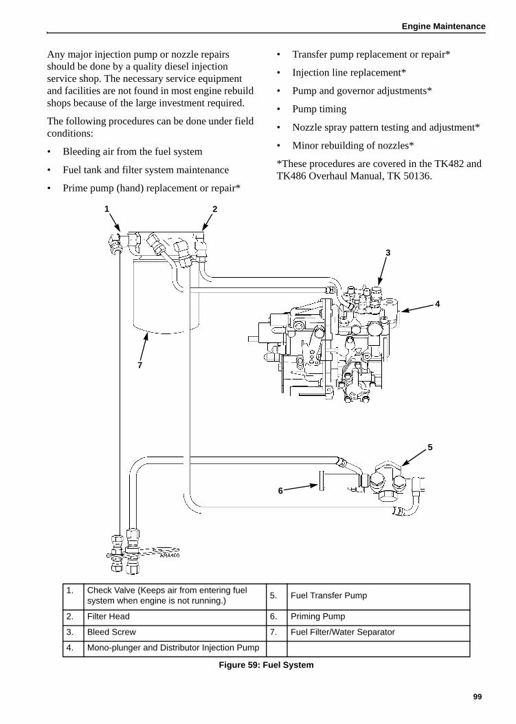
Engine Maintenance
Any major injection pump or nozzle repairs should be done by a quality diesel injection service shop. The necessary service equipment and facilities are not found in most engine rebuild shops because of the large investment required.
The following procedures can be done under field conditions:
• Bleeding air from the fuel system
• Fuel tank and filter system maintenance
• Prime pump (hand) replacement or repair*
• Transfer pump replacement or repair*
• Injection line replacement*
• Pump and governor adjustments*
• Pump timing
• Nozzle spray pattern testing and adjustment*
• Minor rebuilding of nozzles*
*These procedures are covered in the TK482 and TK486 Overhaul Manual, TK 50136.
7
6
5
4
3
1 2
1. Check Valve (Keeps air from entering fuel system when engine is not running.)
5. Fuel Transfer Pump
2. Filter Head 6. Priming Pump
3. Bleed Screw 7. Fuel Filter/Water Separator
4. Mono-plunger and Distributor Injection Pump
Figure 59: Fuel System
99

Engine Maintenance
Fuel Return Line ReplacementThe fuel return lines (hoses) and end cap on the fuel injection nozzles should be changed every 10,000 engine operating hours. The return line kit (P/N 10-373) contains new return lines, clamps, an end cap, and a decal like the one shown below. This decal is was added to production units in January of 2005. The decal is located near the unit serial plate. The date and engine hours must be entered on the decal when the fuel return lines are changed.
Figure 60: Fuel Return Line Replacement Decal
Use the following procedure to replace the fuel return lines and end cap.
1. Remove the clamps, the end cap, the short fuel return lines between the injection nozzles, and the long fuel return line from the injection nozzle to the banjo fitting on the injection pump.
2. Discard the old clamps, end cap, and fuel return lines.
3. Install the end cap and clamp. Note that the end cap has a larger OD than the other hoses and requires the larger clamp.
4. Install the fuel return lines and clamps. It may be necessary to adjust the banjo fitting slightly to obtain the straightest routing for the long return line.
5. Be sure all the fittings are tight and check for leaks.
6. Write the date and engine hours on the decal.
Bleeding the Fuel SystemThe fuel system must have the air bled out if any of the following circumstances occur:
• If the fuel tank becomes empty
• If repairs are made to the fuel system
• If air gets into the system for any other reason.
NOTE: MAKE SURE the fuel tank vent is kept open. If the vent becomes clogged, a partial vacuum develops in the tank, and this increases the tendency for air to enter the system.
To bleed air from the fuel system:
1. Loosen the bleed screw on the injection pump about one turn.
1. End Cap 4. Short Fuel Return Lines
2. Larger Clamp 5. Long Fuel Return Lines
3. Smaller Clamps
Figure 61: Fuel Return Line Replacement
1
2
3
4
3
3
5
3
1. Bleed Screw 2. Priming Pump
Figure 62: Injection Pump
1
2
100

Engine Maintenance
2. Unscrew the priming pump handle and manually prime the fuel system until air bubbles are no longer visible in the fuel coming out of the bleed screw.
3. Tighten the bleed screw and screw the priming pump handle back in.
4. Loosen the injection lines at the injection nozzles.
5. Crank the engine until fuel appears at the nozzles.
6. Tighten the injection lines.
7. Start the engine and observe the engine run for a few minutes. If the engine fails to start, or starts but stops in a few minutes, repeat the procedure.
Water in the Fuel SystemWater in the fuel system can damage the injection pump and nozzles. This damage will subsequently cause more expensive damage to the engine. A large accumulation of water in the bottom of the fuel tank will stop a diesel engine. Water should be drained off during scheduled maintenance inspections. Let the tank set idle for an hour before removing the drain plug from fuel tank. Let water and fuel drain into a container until only fuel is draining from tank. Replace drain plug. DO NOT steam clean fuel tank caps.
NOTE: Some fuel tanks have a check valve in the drain plug fitting. Push the check valve open with a small screw driver to drain water and fuel.
Single Element Fuel Filter/Water Separator ReplacementA single element fuel filter/water separator removes contaminates and water from the fuel. Two orifices in the filter head control the pressure in the fuel system by allowing a certain amount of fuel to return to the tank. One orifice is located in the center of the filter head. It bleeds off water and returns it to the fuel tank. The other orifice is located off-center on the filter head and bleeds off air.
1. Unscrew the filter using a strap wrench. Drain filter. Properly dispose of fuel and filter.
2. Fill the new filter with clean fuel through one of the small openings in the top of the filter body. Do not use the center hole to add fuel to the filter or unfiltered fuel may reach the injection pump. Filling the filter with fuel purges air from the filter.
3. Clean the filter head seal surface. Lubricate filter seal with clean fuel.
4. Hand tighten the filter. Then tighten 1/4 turn more using a strap wrench.
Draining Water from Fuel TankWater run through the system may damage the injection pump or nozzles. Damage to the fuel system will subsequently cause more expensive damage to the engine. A large accumulation of water in the bottom of the fuel tank will stop a diesel engine. Water should be drained off during scheduled maintenance inspections to prevent breakdowns. Drain the water off after the fuel tank and unit have remained idle for an hour.
1. Place a container under the fuel tank to catch the draining water and fuel.
2. Remove the drain plug from the bottom of the fuel tank.
NOTE: Some fuel tanks have a check valve in the drain plug fitting. Push the check valve open with a small screw driver to drain the tank.
3. Let the water and fuel drain into the container until no water is visible in the fuel draining from the tank. If the water and fuel do not drain freely, the vent may be plugged. If so, clean or replace the vent.
4. Install the drain plug.
Engine Speed AdjustmentWhen the diesel engine fails to maintain the correct engine speed, check the following before adjusting the speed:
1. Bleed the air out of the fuel system. Check the speed.
2. Bleed the air out of the nozzles. Check the speed.
101

Engine Maintenance
Adjustment Procedure for Standard UnitsMake the engine speed adjustments with the engine fully warmed up.
1. Turn the refrigeration unit off so there is no load on the engine.
2. Start the unit and use the Data Menu and the Internal States submenu (or the Commands Menu and the System Setup submenu) to check the engine speed. The engine speed should be 1890 ± 10 RPM with No Load.
3. Loosen the jam nut on the speed adjustment screw.
4. Adjust the screw to change engine RPM.
5. Tighten the jam nut, when the speed is correct.
Adjustment Procedure for Units with EcoPower OptionMake the engine speed adjustments with the engine fully warmed up.
1. Turn the refrigeration unit off so there is no load on the engine.
2. Start the unit.
3. Enter the Commands Menu and then enter the System Setup submenu. See “System Setup” on page 66.
4. Set the Speed Solenoid to Off in the System Setup submenu.
5. Check the engine speed. The engine speed should be 1550 + 10/-0 RPM with No Load and the Speed Solenoid Off.
a. If necessary, loosen the jam nut on the low speed adjustment screw.
b. Adjust the low speed adjustment screw to change engine RPM.
c. Tighten the jam nut on the low speed adjustment screw when the speed is correct.
6. Set the Speed Solenoid to On in the System Setup submenu.
7. Check the engine speed. The engine speed should be 1890 ± 10 RPM with No Load and the Speed Solenoid On.
a. If necessary, loosen the jam nut on the high speed adjustment screw.
b. Adjust high speed adjustment screw to change engine RPM.
c. Tighten the jam nut on the high speed adjustment screw when the speed is correct.
8. Exit the System Setup submenu by pressing the ESCAPE key as necessary to return to the Main Menu.
1. Fuel Solenoid
2. Speed Adjustment Screw
Figure 63: Engine Speed Adjustment for Standard Unit
2
1
1. Speed Solenoid
2. Low Speed Adjustment Screw
3. High Speed Adjustment Screw
Figure 64: Engine Speed Adjustment for Units with EcoPower Option
3
1
2
102

Engine Maintenance
Integral Fuel SolenoidThe fuel solenoid contains 2 coils: the pull-in coil, and the hold-in coil. The pull-in coil draws approximately 35 to 45 amperes at 12 volts. The hold-in coil draws approximately 1 ampere at 12 volts. The pull-in coil must be energized to move the injection pump governor linkage to the fuel “ON” position. Once the governor linkage is in the fuel “ON” position, the hold-in coil will keep the linkage in the fuel on position until the 8D circuit is de-energized. The pull-in coil must be de-energized after a few seconds to keep it from being damaged.
DIagnosing the Integral Fuel Solenoid SystemNOTE: The fuel solenoid pull-in coil may require 35 to 45 amperes to pull the solenoid plunger in. The unit’s battery must be in good condition. If the battery has enough power to crank the engine over, it has enough power to energize the fuel solenoid pull-in coil.
If you suspect that the engine does not operate because the fuel solenoid is not operating correctly, use the following procedure:
1. Check the operation of the fuel hold relay and the fuel pull relay.
a. Go to the Commands Menu and use the PTI submenu or the Manual Function Test submenu to test the relays. See “Commands Menu” on page 62, “PTI” on page 63, and “Manual Function Test” on page 64.
b. If a relay fail the test, replace the relay.
c. If the relays pass the tests, go to step 2.
2. Disconnect wire 8S from the starter solenoid.
3. Disconnect the fuel solenoid wire connector from the main wire harness.
4. Place the Unit On/Off switch in the “ON” position.
5. Check the voltage on 8D circuit in the main wire harness connector for the fuel solenoid. Refer to Figure 65 or the unit wiring diagram to identify the pins in the wire harness and fuel solenoid connectors.
a. If battery voltage is not present on the 8D circuit, check the 8D circuit and related components for a fault.
b. If battery voltage is present on the 8D circuit, go to step 6.
6. Check CH circuit in the main wire harness at the fuel solenoid connector for continuity to a good chassis ground.
a. If there is no continuity between CH circuit and a good chassis ground, check the CH wire for an open circuit.
b. If there is continuity between CH circuit and a good chassis ground, go to step 7.
7. Turn the unit off.
8. Place a jumper wire between the CH circuit in the connector on the fuel solenoid and a good chassis ground.
9. Test the pull-in coil by momentarily placing a jumper between the 8DP circuit pin in the connector on the fuel solenoid and the positive
1. Pin B: White (8DP) Wire
2. Pin A: Red (8D) Wire
3. Pin C: Black (CH) Wire
4. Fuel Solenoid and Connector
5. Main Wire Harness Connector and Pins:
Pin A = 8D
Pin B = 8DP
Pin C = CH
Figure 65: Integral Fuel Solenoid Harness Connections
AJA2080
8DP
1
3
4
8D
2
5CH
103

Engine Maintenance
battery terminal. The fuel solenoid should make a definite click when the pull-in coil is energized. It should click again when the pull-in coil is de-energized.
NOTE: The pull-in coil may draw 35 to 45 amperes so do not leave the jumper connected to pin 8DP for more than a few seconds.
a. If the pull-in coil does not energize, check the resistance of the pull-in coil by placing an ohmmeter between 8DP circuit and the CH circuit in the connector on the fuel solenoid. The resistance of the pull-in coil should be 0.2 to 0.3 ohms. Replace the fuel solenoid if the resistance of the pull-in coil is not in this range.
b. If the pull-in coil does energize, go to step 10.
10. Test the hold-in coil.
a. Energize the hold-in coil by placing a jumper between the 8D circuit in the connector to the fuel solenoid and the positive battery terminal.
b. Momentarily energize the pull-in coil by placing a jumper between the 8DP circuit in the connector to the fuel solenoid and the positive battery terminal. The fuel solenoid should make a definite click when the pull-in coil is energized, but should not click when the pull-in coil is de-energized.
c. De-energize the hold-in coil by removing the jumper from the 8D circuit and the positive battery terminal. The fuel solenoid should make a definite click when the hold-in coil is de-energized.
d. If the hold-in coil does not function properly, check the resistance of the hold-in coil by placing an ohm-meter between the 8D circuit and the CH circuit in the connector to the fuel solenoid. The resistance of the hold-in coil should be 24 to 29 ohms. If the resistance of the hold-in coil is not in this range, replace the fuel solenoid.
11. Reconnect the main wire harness connector to the fuel solenoid connector.
12. Connect wire 8S to the starter solenoid.
Fuel Solenoid Replacement1. Disconnect wire 8S from the starter solenoid.
2. Disconnect the fuel solenoid wire connector.
3. Remove the old fuel solenoid.
4. Connect the main harness connector to the new fuel solenoid.
5. Place the Unit On/Off switch in the “ON” position to energize the fuel solenoid.
NOTE: The fuel solenoid must be energized when it is being installed. If it is not, the plunger and the linkage may not line up correctly.
6. Place the O-ring in the groove in the end of the fuel injection pump. Make sure that the O-ring is positioned correctly during installation to avoid damage and leaks.
7. Install the new fuel solenoid.
8. Turn the unit Off.
9. Connect wire 8S to the starter solenoid.
1. Integral Fuel Solenoid
2. O-ring
3. Fuel Injection Pump Groove
Figure 66: Integral Fuel Solenoid Components
AXA0298
104

Engine Maintenance
Injection Pump Service and Timing
Injection Pump RemovalThe injection pump drive gear will not fit through the gear housing when removing the pump. The gear must be separated from the pump using tool P/N 204-1011. When this tool is used, it is not necessary to remove the water pump belt, fuel pump, crankshaft pulley, crankshaft seal or front plate. See Figure 69 “Injection Pump Gear Tool” on page 106.
1. Note the alignment of the index marks on the injection pump and the gear case. The index mark on the injection pump is usually aligned with the single index mark on the gear case. If not, mark it so the injection pump can be returned to the same position when it is reinstalled.
2. Remove the starter for clearance. Also remove the fuel lines, harness and mounting hardware from the injection pump. Cover all injection lines and fuel lines with plastic covers or tape. The smallest amount of dirt can damage the fuel system.
3. Remove the cover plate from the gear case. Remove the nut and lockwasher that secure the gear to the injection pump shaft. Use a shop rag to prevent the lock washer or nut from falling into the gear case.
NOTE: The injection pump gear assembly is made of three pieces; the flange, the gear, and the transfer pump cam. Do not loosen or remove the four bolts that fasten the gear to the flange because that changes the timing.
4. Use the hardware from the cover plate to attach the tool plate (P/N 204-1011) to the gear case. Attach the plate with the marked side pointing up and out away from the case.
5. Align the threaded holes in the injection pump gear with the two holes in the tool plate by rotating the engine crankshaft. Attach the gear to the tool plate with the screws provided with the tool plate.
6. Thread the long screw into the small end of the adapter (both parts are supplied with the tool plate). Insert the adapter into the tool plate. Carefully align the screw over the center
1. Index Marks
Figure 67: Index Mark Location
1
1. Index Mark on Injection Pump
2. Index Mark on Gear Case
Figure 68: Index Mark Alignment
1 2
105

Engine Maintenance
of the injection pump shaft. Then rotate the screw to force the injection pump shaft from the gear.
7. Remove the screw and adapter, leaving the tool plate in position. This holds the gear in the proper tooth alignment until the injection pump is re-installed.
Injection Pump Installation1. Rotate the injection pump shaft to align the
key with the keyway in the gear. Take care to make sure the key mates with the keyway. Then insert the injection pump shaft into the gear.
2. Fasten the injection pump to the gear case using the correct hardware. Make sure to align the index marks on the injection pump and the gear case like they were in step 1 of “Injection Pump Removal”.
NOTE: If a different injection pump is being installed, see “Injection Pump Timing” on page 107 to set the timing.
3. Remove the screws that hold the gear to the tool plate and remove the tool plate.
4. Fasten gear to injection pump shaft with a lock washer and nut. Use a shop rag to prevent the lock washer or nut from falling into the gear case. Torque the nut to 58 to 65 ft-lb (78 to 88 N•m).
5. Fasten the cover plate to the gear case. Install the fuel lines, harness and mounting hardware from the injection pump. Also install the starter.
1. Injection Pump 5. Adapter (Tool)
2. Gear Case 6. Tool Long Screw (Tool)
3. Cover Plate 7. Tool Short Screw (Tool)
4. Cover Plate Bolt 8. Tool Plate (Tool)
Figure 69: Injection Pump Gear Tool
1
2
6
3
7
4
5
8
106

Engine Maintenance
Injection Pump TimingUse this timing procedure when installing a new injection pump. It is not necessary to use this timing procedure when removing and reinstalling the original injection pump. In that case, align the index marks on the injection pump and the gear case as they were before removing the injection pump.
1. Before removing the old injection pump, note the alignment of the index marks on the injection pump and the gear case. The index mark on the injection pump is usually aligned with the index mark on the gear case. If not, make a mark on gear case in line with the index mark on the injection pump (see Figure 72).
2. Clean the area with brake cleaner or something similar. Place an injection angle sticker on the gear case so the center line on the sticker is aligned with the index mark on the injection pump. An injection angle sticker is provided with the new injection pump.
1. Index Marks
Figure 70: Index Mark Location
1. Index Mark on Injection Pump
2. Index Mark on Gear Case
Figure 71: Index Mark Alignment
1
1 2
1. Index Mark on Injection Pump
2. Existing Index Mark on Gear Case
3. Make New Mark on Gear Case If Needed
Figure 72: Marking Gear Case
1. Index Mark on Injection Pump
2. Injection Angle Sticker
Figure 73: Place Injection Angle Sticker on Gear Case
1. –1.0 Degrees Mark
2. Center Line (0 Degrees Mark)
3. +1.0 Degrees Mark
Figure 74: Injection Angle Sticker
12
3
1 2
1
3
2
0.5 Degrees
107

Engine Maintenance
3. Remove the old injection pump. Use the injection pump gear tool P/N 204-1011 to remove the injection pump gear without removing the timing gear cover (see “Injection Pump Removal” on page 105).
NOTE: Remove the injection pump gear by removing the nut and lock washer that secure the injection pump gear assembly to the injection pump shaft. The injection pump gear assembly is made of three pieces; the flange, the gear, and the transfer pump cam. Do not loosen or remove the four bolts that fasten the gear to the flange because that changes the factory-set timing. The EPA certification is based on the factory-set timing. If the factory-set timing is changed, the EPA certification is void.
4. Record the injection angle marked on the old injection pump (see the following photographs). The injection angle mark is located on the side of the pump facing the engine. The injection angle mark on the pump does not use a decimal point. Add a decimal point before the last digit of the injection angle mark to get the injection angle. The injection angle mark in the following photographs is 67. That equals an injection angle of 6.7 degrees.
NOTE: If you cannot read the injection angle mark, contact Yanmar (e-mail both Koichi Sawada at [email protected] and Hisashi Hamada at [email protected]) with the injection pump serial number or the engine serial number and they will provide the injection angle. The injection pump serial number is located on the bottom of the sticker on the injection pump.
1. Do Not Loosen or Remove These Four Bolts
2. Remove Nut and Lock Washer
Figure 75: Removing Injection Pump Gear
Examples
Injection Angle Mark Injection Angle
67 6.7 Degrees
85 8.5 Degrees
1
2
1
1
1
1. Injection Angle Mark
Figure 76: Injection Angle Mark Location
1. Injection Angle Mark
Figure 77: Injection Angle Mark
1. Injection Pump Serial Number
Figure 78: Injection Pump Serial Number Location
1
1
1
108

Engine Maintenance
5. Record the injection angle marked on the side of the new injection pump.
6. Calculate the injection angle difference by subtracting the injection angle of the old injection pump from the injection angle of the new injection pump.
7. Install the new injection pump on the gear case and position it so the index mark on the injection pump is aligned with the mark equal to the injection angle difference on the injection angle sticker (see the following examples). Tighten the injection pump mounting nuts when the index mark is aligned as necessary with the injection angle sticker.
8. Install the injection pump gear, lock washer, and nut. Torque the nut to 58 to 65 ft-lb (78 to 88 N•m).
NOTE: If the timing gear cover was removed to remove the injection pump gear, make sure the timing marks on the timing gears are aligned as shown below. It helps to install the idler gear last when aligning the timing marks.
NOTE: The oil pump is located in the timing gear cover on TK486V engines. The inner rotor of the oil pump fits around the crankshaft gear. Make sure that the flat sides of the inner rotor are aligned with the flat sides on the crankshaft gear when installing the timing gear cover.
Examples
Injection Angle of New Injection Pump (Degrees)
8.5 6.1
– Injection Angle of Old Injection Pump (Degrees)
– 6.7 – 6.7
= Injection Angle Difference (Degrees)
= +1.8 = –0.6
1. Injection Pump Index Mark at –0.6 Degrees
2. Injection Pump Index Mark at +1.8 Degrees
Figure 79: Examples of Injection Pump Index Mark Alignment with Injection Angle Sticker
1
2
1. Fuel Injection Pump Gear
2. Idler Gear
3. Camshaft Gear
4. Crankshaft Gear
Figure 80: Timing Mark Alignment
1. Crankshaft Gear
2. Oil Pump Cover
3. Outer Rotor
4. Inner Rotor
5. Timing Gear Cover
6. Flat Sides on Inner Rotor
7. Flat Side on Crankshaft Gear
Figure 81: Align Flat Sides of Crankshaft Gear with Flat Sides of Inner Rotor in Timing Gear Cover
1 3
2
4
1
52
7
34
6
109

Engine Maintenance
Trochoid Feed PumpThe TK486V engine has a trochoid feed pump on the fuel injection pump. The trochoid feed pump supplies fuel to the injection pump at a pressure of 450 to 600 kPa (65 to 87 psi) in high speed. Check the outlet pressure of the trochoid feed pump by removing the plug and attaching a pressure gauge to the port shown below. The plug has M12x1.25 threads. You will have to make an adaptor to attach a pressure gauge. Replace the trochoid feed pump if the outlet pressure is below the pressure specifications in the following table.
If the seal in the trochoid feed pump fails, it could allow some fuel to leak into the engine oil. A faulty injection nozzle or fuel transfer pump can also dilute the engine oil with fuel. Replace the trochoid feed pump if the engine oil is being diluted with fuel and a faulty injection nozzle or fuel transfer pump is not the cause.
Use the following procedure to replace the trochoid feed pump.
1. Remove the four hex head screws that attach the trochoid feed pump to the injection pump. Do not remove the two Allen head screws.
2. Remove the trochoid feed pump from the injection pump.
NOTE: The gear on the trochoid feed pump is lubricated with engine oil. Some engine oil might leak out of the injection pump when the trochoid feed pump is removed. The trochoid feed pump does not need to be timed when it is installed.Clean the area on the injection pump from which the trochoid feed pump was removed.
3. Place new O-rings on the new trochoid feed pump and make sure it is clean.
4. Place the new trochoid feed pump on the injection pump.
Trochoid Feed Pump Outlet Pressure
Cranking 103-206 kPa (15-30 psi)
Low Speed 206-345 kPa (30-50 psi)
High Speed 450-600 kPa (65-87 psi)
1. Trochoid Feed Pump Outlet Pressure Port
2. Trochoid Feed Pump
Figure 82: Trochoid Feed Pump Location
1
2
1. Allen Head Screws (Do Not Remove)
2. Hex Head Screws
Figure 83: Trochoid Feed Pump Removal
1. O-Rings
Figure 84: Trochoid Feed Pump
21 1
1
1
110

Engine Maintenance
5. Install and tighten four hex head screws that attach the trochoid feed pump to the injection pump. Torque the hex head screws to 8 to 10 N•m (6 to 7 ft-lb).
Cold Start DeviceThe TK486V engine has a cold start device located on the fuel injection pump. The cold start device has a plunger that retracts at engine coolant temperatures below 5 C (41 F) to advance the injection timing approximately 2 degrees. The plunger controls the position of a piston in the injection pump to change the timing. The plunger is extended and the injection timing is normal at engine coolant temperatures above 5 C (41 F). Check the operation of the cold start device if it is difficult to start the engine in cold weather.
NOTE: Do not pull the plunger out of a cold start device because that will damage it.
Checking Cold Start Device Operation
Use the following procedure to check the operation of the cold start device. The engine coolant temperature must be below 0 C (32 F) to start the procedure.
1. Place the On/Off switch in the On position.
2. Enter the Analog Inputs submenu in the Data Menu before the engine starts and check the coolant temperature to make sure it is below 0 C (32 F).
3. Let the engine start, then enter the Internal States submenu in the Data Menu to check the engine rpm. The engine rpm should be approximately 100 rpm higher than normal (see Specifications).
4. Let the engine run to warm up and use Analog Inputs and Internal States submenus to check the coolant temperature and engine rpm. When the coolant temperature rises above 5 C (41 F), the engine rpm should drop back to normal. Replace the cold start device if the engine rpm does not drop approximately 100 rpm when the engine warms up.
Cold Start Device Replacement
1. Drain the engine coolant.
2. Remove the banjo bolt that fastens the engine coolant fitting to the cold start device. Use a backup wrench on the cold start device if necessary.
1. Plunger (Extended)
Figure 85: Cold Start Device
1
1. Banjo Bolt
2. Engine Coolant Fitting
3. Coolant Hoses to Cold Start Device
Figure 86: Remove Engine Coolant Fitting
1
2
3
111

Engine Maintenance
3. Remove the cold start device from the injection pump fitting. Use a backup wrench on the injection pump fitting if necessary.
4. Make sure the piston inside the injection pump fitting is clean.
5. Install the new cold start device with a new O-ring in the injection pump fitting. Torque the cold start device to 30 to 35 N•m (22 to 26 ft-lb).
6. Install the coolant fitting and banjo bolt on the cold start device. Torque the banjo bolt to 22 to 25 N•m (16 to 18 ft-lb).
7. Refill the engine cooling system and make sure to bleed the air from the cooling system.
Adjusting Engine Valve ClearanceValve clearance should be checked as required. It is very important that valves be adjusted to the correct specifications for satisfactory engine operation. Insufficient valve clearance will result in compression loss and misfiring of cylinders. This will result in burned valves and seats. Excessive valve clearance will result in noisy valve operation and abnormal wear of the valves and rocker arms. The intake and exhaust valves are adjusted with the valve in the closed position.
Figure 89: Adjusting the Valve Clearance
Complete the following steps to adjust the engine value clearance.
1. Remove the rocker arm cover.
2. Remove the round cover (plug) from the timing mark access hole on the front of the bell housing.
3. Place the engine at top dead center of the compression stroke for the number one cylinder.
a. Rotate the engine in the normal direction of rotation (clockwise viewed from the water pump end). Rotate the engine until the 1-4 timing mark on the flywheel lines up with the index mark in access hole.
1. Cold Start Device
2. Injection Pump Fitting
Figure 87: Remove Cold Start Device
1. Piston
Figure 88: Clean Piston
1
2
1
WARNING: Loosen all of the injection lines at the injection nozzles to prevent the possibility of the engine firing while it is being rotated.
AXA0304
112

Engine Maintenance
b. Check the rocker arms on the number one cylinder.
c. If the rocker arms are loose, the engine is at top dead center of the compression stroke for the number one cylinder.
d. If the rocker arms are tight, the engine is at top dead center of the exhaust stroke for the number one cylinder. Rotate the engine 360 degrees to place the engine at top dead center of the compression stroke for the number one cylinder.
4. Check the valve clearance of both valves for the number one cylinder with a feeler gauge. Also check the valve clearance for the intake valve for the number two cylinder, and the exhaust valve for the number three cylinder. The clearance for both the intake and exhaust valves should be 0.15 to 0.25 mm (0.006 to 0.010 in.).
NOTE: Check to make sure that the valve stem cap is in good condition and is positioned squarely on the top of the valve stem. Replace the valve stem cap if it shows significant wear.
5. Loosen the locknut and adjust the valves as required by turning the adjustment screw.
6. Hold the adjustment screw while tightening the locknut.
7. Recheck the valve clearance.
8. Rotate the engine one full turn (360 degrees) to place the engine at top dead center of the compression stroke for the number four cylinder. Rotate the engine clockwise as viewed from the water pump end. Align the 1-4 timing mark on the flywheel with the index mark in the access hole. This places the engine at top dead center of the compression stroke for the number four cylinder.
9. Check and adjust both valves for the number four cylinder.
10. Place the engine at top dead center of the compression stroke for the number four cylinder. Also check the valve clearance for the intake valve for the number three cylinder, and the exhaust valve for the number two cylinder. The clearance for both the intake and exhaust valves should be 0.15 to 0.25 mm (0.006 to 0.010 in.).
11. Replace the rocker arm cover and the timing mark access hole cover. Tighten the fuel injection lines when finished.
1. Timing Mark
2. Top Dead Center Mark for Cylinders 1 and 4
3. Top Dead Center Mark for Cylinders 2 and 3
Figure 90: Timing Marks
AJA2085
1 1 32
Engine Rear Flywheel
End
Front Pulley End
Cylinder No. 1 2 3 4
Valve Arrangement E I E I E I E I
Piston in No. 1 cylinder is at TDC on compression stroke
O O O O
Piston in No. 4 cylinder is at TDC on compression stroke
Figure 91: Valve Adjustment and Cylinder Configurations
Θ Θ Θ Θ
113

Engine Maintenance
Belt Tension Adjustment and Belt ReplacementNOTE: Belt tension specifications are measured using Thermo King belt gauge tool, P/N 204-427.
Belts should be regularly inspected during unit pretrip for wear, scuffing or cracking and correct tension.
Correct belt tension is critical for correct unit operation. Belts that are too loose will slip, squeal or whip causing excessive vibration levels and poor unit performance. Belts that are too tight will put too much strain on the belt fibers and bearings, causing premature belt and bearing failures. New belts should be tensioned cold.
NOTE: DO NOT attempt to remove or install belts without loosening adjustments. Belts that are installed by prying will fail prematurely due to internal cord damage.
The water pump belt tension should read 15 to 35 on the belt tension gauge.
1. Remove the nuts from the water pump pulley.
2. Remove the pulley sliding section and add or remove shims to adjust the belt tension.
3. Reinstall the belt on the pulley and replace the sliding pulley section on the pulley.
4. Tighten the mounting nuts on the water pump pulley.
5. The belt tension should read 15-35 on the belt tension gauge.
NOTE: When adjusting the belt tension using shims and adjustable pulleys, the belt may still feel loose when the belt tension gauge indicates the correct tension. Allow 18 to 25 mm (0.75 to 1.0 inch) deflection with 3 to 4 kg (6 to 9 lb) of force.
WARNING: DO NOT jump belts on by cranking the engine. Personal injury may result.
WARNING: DO NOT attempt to adjust belts with the unit operating.
WARNING: With the unit On/Off switch in the “ON” position, the unit may start operation at any time without prior warning. Switch unit On/Off switch to “OFF” position before performing maintenance or repair procedures.
Water Pump Pulley (Items 1 - 5)
1. Fixed Pulley Section
2. Spacer
3. Shims (4)
4. Sliding Pulley Section
5. Nut (4)
6. Belt
7. Crankshaft Pulley
Figure 92: Water Pump Fan Belt
AJA2086
1 2 3 4 5
7
6
114

Alternator Operation and Diagnosis
General DescriptionThe 460/230 Vac alternator system consists of two principal components: the main alternator, and the SG+ Controller.
The main alternator may be subdivided into the 4-pole main rotating field and the main stator winding.
The main rotating field, the rotating rectifier and the exciter armature are all mounted on a common shaft. Output of the exciter is rectified by the shaft mounted rotating bridge rectifier. This provides excitation to the main alternator rotating field.
The SG+ Controller energizes (and controls) the exciter field. The output from the main winding builds up until the voltage and amperage reaches the rated amount. The controller then decreases field current, and the alternator maintains the proper output voltage.
Dual Voltage AlternatorThe generator set is factory wired for 460V power output. The alternator output can be changed to 230V by changing the jumper wire connections at the terminal strips in the control box. See “Rewiring Procedures for Changing the Generator Set Output Voltage” on page 123.
Figure 93: 460/230 Vac Alternator Component Function
115

Alternator Operation and Diagnosis
Alternator Function
Starting ExcitationThe initial excitation for the alternator is supplied by the SG+ Controller approximately 15 seconds after the engine starts. The controller energizes wire F1, which sends the current through the exciter field to build voltage in the stator windings. The current then travels through wire F2 where the circuit is completed to chassis ground.
NOTE: When the Delayed Cold Start feature is set to ON, the exciter field is not energized until the engine temperature rises to 32 C (90 F).
Running Excitation and ControlThe magnetic field that was formed in the exciter field stator winding by current from the controller induces a current in the exciter rotating winding. This current is changed from three-phase ac to dc by the rotating rectifier. The dc current is transferred to the main alternator field winding. The main alternator field now becomes magnetic.
The magnetic field formed in the main field winding now induces a voltage in the alternator stator windings. This voltage is either 230 Vac or 460 Vac, 3-phase, depending on stator connections.
It is sent out of the alternator stator leads to the power plug and then to the load. The controller is tapped into the alternator stator leads. The controller reads the alternator output voltage and steps this voltage down to around 12 Vac (1/20th of output voltage). This current is rectified to dc current and is used to charge the battery and energize the exciter field. The controller monitors the alternator output voltage and adjusts the output to the exciter field as necessary to maintain the alternator output at the correct voltage.
Battery ChargingThe unit battery is recharged by the alternator through the controller, which performs the functions of a voltage regulator and rectifier. Fuse SI2 (30 amps) protects the battery charger output circuit.
Overload ShutdownThe overload shutdown is provided by the controller.
If an overload condition becomes more than temporary, the reduction in alternator output voltage due to the overload causes the controller to increase field current through wire F2. The controller senses the overload current and then de-energizes the fuel solenoid to stop the engine.
If the controller shuts down unit operation, it indicates one of the following:
1. There is a malfunction in the load causing the load to fail to start or to draw single phase current.
2. The engine speed or power is low due to improper speed adjustment, fuel supply problems or other mechanical conditions while the generator is supplying motor starting current to the load.
3. Internal component failure in the excitation control system, resulting in excessive field current. This includes possible malfunction of protective elements in the excitation control.
4. Failure in the alternator rotating elements (exciter armature, rotating diode assemblies or main field) can cause the regulator to supply excessive exciter field current.
5. Engine shutdown on low engine oil level, low oil pressure or high water temperature.
116

Alternator Operation and Diagnosis
Alternator Diagnosis
Preliminary ChecksBefore attempting the more complicated diagnosis procedures, check the following items to ensure a superficial problem is not overlooked.
NOTE: Further diagnosis is a waste of time until these items are checked, since a problem in one of these areas will influence test results.
1. If the generator malfunction is accompanied by excessive black exhaust smoke and engine lugging, double check all possible engine problems such as fuel supply, injection timing, engine speed, restricted air cleaner, etc.
2. Disconnect the refrigeration unit from the generator and check the output voltage at the plug. Voltage between the three phases should be between 230 to 250 Vac or 460 to 500 Vac depending on engine speed and whether the alternator stator is wired for 230 or 460 Volt operation. All three phases should be within 3% of each other. If the voltages appear normal, make sure the refrigeration unit is not at fault. Reconnect refrigeration unit and run in Cool mode. Check the amperage draw with an induction type ammeter (amprobe), and compare it with the load plate on the refrigeration unit.
3. Check the condition of the generator set battery. A discharged unit battery can increase the voltage regulator output, causing the generator output voltage to be high. The unit battery should have a minimum voltage of 12 Volts. Perform a load test on the battery to check it’s condition.
4. Check all push-in plugs on control circuits for loose pins or sockets. Make sure all wire terminals are tight.
Test InstrumentsIf the preceding checks did not uncover the cause of the malfunction, more extensive diagnosis procedures will be required. The following tests will require various electrical test instruments, and the technician performing the tests should have a good working knowledge of their basic electrical principles.
The tests are intended to determine whether the source of difficulty lies in the generator itself or in the excitation control system. Following the procedures carefully will, in many cases, avoid unnecessary dismantling and reassembly of the generator when easily corrected problems may exist in the external circuitry.
The test instruments required:
1. AC-DC voltmeter 2.5 Volts to 500 V ranges (± 2% max. error).
2. AC induction ammeter (amprobe).
3. DC ammeter (preferably induction type TK No. 204-449).
4. Ohmmeter.
5. Megohmmeter (Megger®)
Alternator MalfunctionsListed below are the categories in which most generator malfunctions will fall. Following each category are a number of possible component failures that may cause the malfunction. Listed with each component is the test used to check the component.
NOTE: Always use Test No. 1 first to determine if the alternator or the controller is at fault.
1. Generator set will not pick up the load (low or no output voltage).
a. Exciter field circuit in alternator is open circuit (Test No. 2).
b. Alternator stator, main rotating field, rotating rectifier or rotating exciter armature is defective (Test No. 3).
2. Generator set tries to pick up the load but engine labors excessively, eventually causing an overload condition and causing the Relay Board to shutdown unit operation.
a. Mechanical problems with engine (see preliminary check 1).
b. Excessive load from refrigeration unit malfunction (see preliminary check 2).
c. Defect in rotating field, rotating bridge, alternator main field or alternator stator (Test No. 3).
117

Alternator Operation and Diagnosis
3. Generator set causes the controller to shut-down unit without apparent overload.
a. Exciter field circuit shorted or low resistance (Test No. 2).
b. Defective rotating exciter armature, rotating rectifier, exciter field circuit or main alternator stator (Test No. 3).
c. Engine speed too low. Reset engine speed to 1890 ± 10 RPM No Load.
4. Generator set output voltage too high.
a. Unit battery discharged (see preliminary check 3).
b. Shorted exciter armature (Test No. 3).
5. Unit battery undercharged.
a. Battery defective.
b. Fuse SI2 bad.
c. Controller fault.
Test No. 1This test will determine whether the alternator or the controller is causing the malfunction.
1. Start the engine and make sure speed is 1890 ± 10 RPM No Load.
2. Check the voltage on the exciter field circuit at the J6 connector on the microprocessor PC board. Wire F1 is the positive output. Wire F2 is the chassis ground. There should be a positive 8.7 ± 1.0 Vdc reading between the F1 and F2 circuits.
If there is voltage between the F1 and F2 wires at J6 connector on the microprocessor PC board, the controller is good.
NOTE: Alarm Code 114 indicates that the controller is functioning properly, but there is a problem with the exciter field circuit. Check the exciter field circuit (Test No. 2).
Test No. 2Test 2 determines the condition of the exciter field circuit.
1. Disconnect the field wires F1 and F2 from the control box circuitry. Measure the resistance of the field circuit (F1 to F2). The standard value is 13.9 (± 10%) ohms at 77 F (25 C).
2. Measure F1 or F2 to GND for possible shorted to ground coils.
3. Reconnect the field wires.
Test No. 3Test 3 includes testing the main alternator-stator, the rotating field, the rotating rectifier, and the rotating field armature. All tests must be made with reliable equipment.
1. Main alternator stator windings.
a. Disconnect the stator leads from terminal boards in the control box, and check for continuity between the following pairs: T1-T4, T2-T5, T3-T6, T7-T10, T8-T11, T9-T12. The resistance between any of the above pairs should be 0.114 (± 10%) ohms at 77 F (25 C).
A very sensitive instrument (such as a Kelvin bridge) must be used for resistance readings. A standard ohmmeter will suffice to check continuity.
b. Using a megohmmeter, check for insulation break-down between each pair of leads.
c. Remove the end bell for the remaining checks.
CAUTION: Remember that hazardous electrical potentials will be present on alternator output terminals on exciter control. The ground (negative) connection bypasses all exciter control overload protection.
CAUTION: Care must be exercised to avoid damage to the alternator in the event there is an internal or external short circuit.
118

Alternator Operation and Diagnosis
2. Rotating Rectifier.
Six rectifying diodes mount on the rotating rectifier, three are positive and three are negative.
a. Unbolt each of the diode leads.
NOTE: The diodes must be disconnected for testing, or false test readings may occur.
b. Disconnect main alternator field leads which connect to exciter diode heat sinks.
c. Check each diode in the forward and reverse direction.
When testing diodes:
• Use X100 scale on the ohmmeter
• Reject diodes that have excessive leakage (read less than 100,000 ohms) reverse polarity
• Reject diodes that read low in both directions or “Open” in forward direction.
• Good diodes will have a high resistance reading in one direction and a low reading when ohmmeter leads are reversed
3. Rotating Exciter Armature
a. With rectifier leads still disconnected from previous checks, test between the following combinations of leads: (CR6-CR4), (CR3-CR1), (CR3-CR2), (CR6- CR5), (CR5-CR4) and (CR2-CR1).
The resistance reading on the ohmmeter for any of the above combinations of leads should be 0.645 (± 10%) ohms at 77 F (25 C).
b. Using the megohmmeter, check from each pair of leads to rotor case.
1. Disconnect all 12 stator leads to test the stator.
Figure 94: Alternator Stator
1. Disconnect the main alternator field lead to test the diodes.
Figure 95: Rectifying Diodes
AJA20891
AJA2090
1
1. Main Field
2. Exciter Rotor
3. Exciter Field
Figure 96: Alternator Test No. 3: Exciter Armature
AXA0323
119

Alternator Operation and Diagnosis
4. Main Alternator Field.
a. Measure the resistance of the main alternator field. Standard value is 2.5 (± 10%) ohms.
b. Measure the main field to rotor or ground with a megohmmeter.
MegohmmeterThe use of a megohmmeter can be a valuable addition to the repair and maintenance of the generator set. The megohmmeter is essentially a high-range resistance meter (ohmmeter) with a built-in direct-current generator. This meter is of special construction with both current and voltage coils-enabling true ohms to be read directly, independently of the actual voltage applied.
The meter gives you a direct reading of insulation resistance in “ohms” or “megohms” (1 megohm = 1,000,000 ohms). For good insulation, the resistance usually reads in the megohm range.
Normally, good insulation has high resistance; poor insulation, relatively low resistance. The actual resistance values can be higher or lower, depending upon such factors as the temperature or moisture content of the insulation (resistance decreases with increase in temperature or moisture). They can be quite different for a generator tested three days in a row, yet not mean bad insulation. What really matters is the trend in readings over a time period, showing lessening resistance and warning of coming problems. Periodic testing is, therefore, your best approach to preventive maintenance. One of the more popular megohmmeters used in the field today is the “Megger®” manufactured by:
AVO Biddle Instruments Bluebell, Pennsylvania 19422 Area Code: (215) 646-9200
They may be contacted for more information on how to use the megohmmeter for testing or about various types of megohmmeters available.
Maintenance ProceduresThe following paragraphs cover detailed maintenance procedures, including disassembly and assembly of equipment for necessary component removal and replacement. Many repair or replacement operations can be performed without extensive disassembly of the generator.
General InspectionInspect the entire unit to see that controls are in order and that there are no loose nuts, bolts, electrical connections or fittings. Inspect for secure engine to generator mountings. Remove any waste material from area around the unit. Check battery connections.
1. Main Field
2. Exciter Rotor
3. Exciter Field
4. Ohmmeter
Figure 97: Alternator Test No. 3: Main Field Winding
AXA0324
WARNING: DO NOT attempt adjustments or changes in wiring while a unit is in operation. The unit generates sufficient voltage to cause severe and possible fatal shock. Use extreme caution when operating in wet or damp locations.
120
Alternator Operation and Diagnosis
InsulationInspect insulation on wires, coils and control components. See that insulation is not frayed, broken or deteriorated. Replace wire having damaged insulation.
Field Coils, Stator WindingsVisually inspect the field coils and stator windings, their leads and connections to determine if they are electrically and mechanically satisfactory. Look for any evidence of overheating, burned or frayed insulation, loose connections, foreign matter, etc.
Generator HousingFeel the alternator housing cautiously for abnormal temperatures as determined by previous experience with the unit. If the generator is overheated, check the winding temperature with thermometer, locate the cause such as lack of ventilation, overload, etc., and correct the condition or shut down the generator. Inspect the generator housing for obstruction of air passages.
Generator BearingAll alternators covered in this manual are fitted with a permanently lubricated bearing which requires no maintenance in normal service.
Impeller FanVisually inspect the impeller fan to ascertain that no vanes are missing. Visually inspect the fan is not encrusted with dirt or other foreign matter to the point where it will not function properly.
CouplingDisc type coupling. Inspect to see that coupling bolts are tight and that the generator is solidly secured to the engine.
121

Alternator Operation and Diagnosis
AXA0325
1. Rotor Assembly 14. Stator and End Bell Assembly
2. Disc, Rotor Drive 15. Stator, Wound
3. Blower, Generator 16. Exciter, Field
4. Rotor 17. Bell, End
5. Key 18. Stud, Bell
6. Spacer, Bearing 19. Cover, End Bell
7. Bearing/Seal, Rotor 20. Screw, Mounting End Bell Cover
8. Exciter Assembly, Rotor 21. Gasket, End Bell Cover
9. Rectifier, Positive Assembly 22. O-ring
10 Rectifier, Negative Assembly 23. Screw, Retainer
11. Nut, Rectifier Assembly 24. Retainer, Exciter
12. Screw, Mounting Rectifier 25. Rotor
13. Screw, Mounting Bearing
Figure 98: Alternator Assembly
122

Alternator Operation and Diagnosis
Rewiring Procedures for Changing the Generator Set Output VoltageThe alternator stator features a 12 lead design that contains two separate windings for each of the three output phases. The 12 leads are numbered T1 through T12. All rewiring is performed inside the control box.
All generator sets are factory wired for 460 Vac power output. 460 Vac operation requires that the two individual windings in each of the three phases be connected in series: T4 tied to T7, T5 tied to T8, and T6 tied to T9. The three output phases are:
230 Vac operation requires that one of the two windings in each of the three phases be connected in parallel: T4, T5, and T6 are tied together. The three output phases are:
Figure 99: Changing Output Voltage
Rewiring Procedure for Changing the Output Voltage from 460 Vac to 230 Vac
1. Refer to the unit wiring diagram for illustrations of the proper wire connections.
2. Disconnect Wires:
a. Remove wire T7 from T4 connection, wire T8 from T5 connection and wire T9 from T6 connection on the main output terminal block.
b. Remove jumper wires on the terminal block from the T4 connection and T5 connection.
3. Reconnect Wires:
a. Install wire T7 lead on L1 (Black Wire) terminal, wire T8 on L2 (White Wire) terminal and wire T9 lead on L3 (Red Wire) terminal.
b. Connect T4 jumper wire lead to J5 wire terminal. Connect T5 jumper wire lead to J6 wire terminal.
4. Change output receptacle to 230 Vac.
5. Change voltage decal and nameplate markings from 460 Vac to 230 Vac.
6. Use the Configuration Menu to change the Output Voltage setting from 460 to 230. See “Configuration Menu” on page 73.
Phase Wires
A (Black) T1
B (White) T2
C (Red) T3
Phase Wires
A (Black) T1, T7 (tied together)
B (White) T2, T8 (tied together)
C (Red) T3, T9 (tied together)
WARNING: Disconnect the unit battery to prevent the unit from accidentally starting during rewiring.
123

Alternator Operation and Diagnosis
124

Structural/Accessory Maintenance
Unit InspectionInspect the unit during unit pre-trip inspection and scheduled maintenance intervals. Look for loose or broken wires or hardware, and other physical damage which might affect unit performance. Repair if required.
NOTE: See Service Guide chapter in this manual for the correct service interval for your unit. 250 or 500 hour inspection/service intervals are required in extreme operating conditions.
Mounting BoltsCheck and tighten all engine and control box mounting bolts every 1,000 operating hours. Unit mounting hardware should be inspected for tightness during every pretrip.
Radiator Fan LocationThe radiator fan and hub assembly mounts on the water pump pulley. When installed, the fan blade should be in the orifice with 65 to 70 percent of the blade width to the air discharge side for proper fan performance.
Mounting Bolt Torque
SGSM Units:
Tubular Mounting Arm to Unit Frame
203 N.m (150 ft-lb)
I-Beam Clamp Screw 203 N.m (150 ft-lb)
SGCM Units:
Mounting Arm to Unit Frame
88 to 115 N.m (65 to 85 ft-lb)
Chassis Clip Bolt 162 to 176 N.m (120 to 130 ft-lb)
SGCO Units:
Upper Clamp Lock clamp with lock pawl
Lower Mounting Bolts 203 N.m (150 ft-lb)
All Units:
TK486 Engine 203 N.m (150 ft-lb)
Exciter Control Box 20 to 27 N.m (15 to 20 ft-lb)
Power Cord Receptacle 20 to 27 N.m (15 to 20 ft-lb)
Fuel Tank 81 to 88 N.m (60 to 65 ft-lb)
1. Radiator Coil Orifice
2. Airflow Direction
3. 65 to 70 Percent of Fan Blade Depth to Air Discharge Side of Orifice
Figure 100: Radiator Fan Blade Placement
AJA2092
1
3
2
125

Structural/Accessory Maintenance
SGSM 3000 Typical Unit Installation1. Attach the mounting arm assemblies on each
end of the unit. Two sets of mounting bolt holes are provided on the mounting arms.
NOTE: The clear insulator pad should be located between the steel mounting arms and the inside of the unit frame members. The stainless steel plate should be placed on the outside of the unit frame members.
2. Move the unit under container or trailer chassis. Place each mounting channel on top of a chassis frame member. Locate each channel as close to the vertical web of the chassis member as possible.
3. Torque the mounting bolts:
• Mounting Arm to Unit Frame: 88 to 115 N.m (65 to 85 ft-lb)
CAUTION: Keep all container or trailer electrical lines and air lines away from the channel to prevent damage during unit installation and operation.
AXA0327
1. Mounting Arm Tube and Channel Assembly
2. Unit Mounting Bracket Assembly
Figure 101: SGSM 3000 Side Mount Installation — Typical
126

Structural/Accessory Maintenance
SGSM 3000 Keener Arm Unit Installation1. Attach mounting arm assemblies to unit with
clamp screw end of the channel facing the rear side of the unit. Torque mounting bolts that fasten mounting arms to the unit to 203 N.m (150 ft-lb).
2. Place mounting arm clamp screw assemblies in open (down) position.
3. Open each slider channel at least 200 mm (8 in.).
4. Move the unit under container or trailer chassis. Place fixed gripper channels on unit over edge of chassis I-beam.
5. Seat the chassis I-beam against the back of both fixed gripper channels. Move each slider channel forward over the back edge of the chassis I-beam.
6. Place the eye bolts over the slider pins by adjusting the bolt length as necessary.
7. Insert quick release pins in eye bolt handles to lock the eye bolts in the closed (lock) position.
8. Place the clamp screw assemblies on the rear edge of the second chassis I-beam.
9. Seat each clamp firmly against the edge of the I-beam and tighten clamp screw. Torque each clamp screw to 203 N.m (150 ft-lb).
AXA0328
1. Clamp Channel 7. Unit
2. Clamp Screw 8. Unit Mounting Bracket Assembly
3. Mounting Arm Clamp 9. Chain and Quick Release Pin
4. Mounting Arm Tube 10. Eye Bolt
5. Slider Channel 11. Slider Pin
6. Fixed Gripper Channel
Figure 102: SGSM 3000 Side Mount Installation — Keener Arm
127
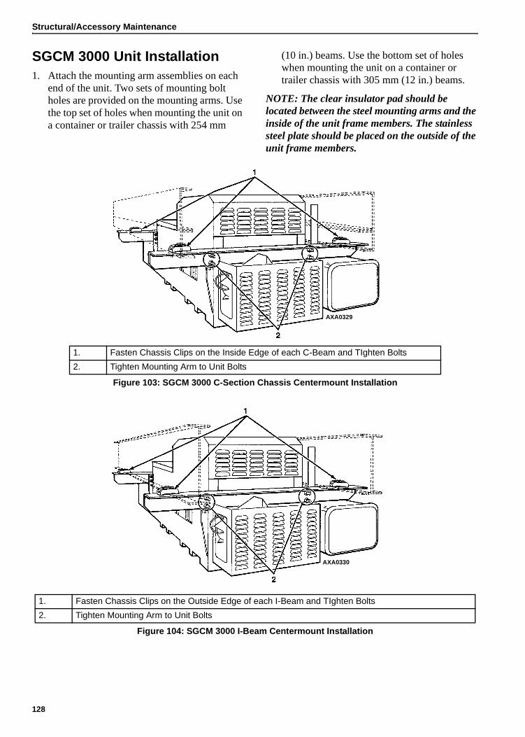
Structural/Accessory Maintenance
SGCM 3000 Unit Installation1. Attach the mounting arm assemblies on each
end of the unit. Two sets of mounting bolt holes are provided on the mounting arms. Use the top set of holes when mounting the unit on a container or trailer chassis with 254 mm
(10 in.) beams. Use the bottom set of holes when mounting the unit on a container or trailer chassis with 305 mm (12 in.) beams.
NOTE: The clear insulator pad should be located between the steel mounting arms and the inside of the unit frame members. The stainless steel plate should be placed on the outside of the unit frame members.
AXA0329
1. Fasten Chassis Clips on the Inside Edge of each C-Beam and TIghten Bolts
2. Tighten Mounting Arm to Unit Bolts
Figure 103: SGCM 3000 C-Section Chassis Centermount Installation
AXA0330
1. Fasten Chassis Clips on the Outside Edge of each I-Beam and TIghten Bolts
2. Tighten Mounting Arm to Unit Bolts
Figure 104: SGCM 3000 I-Beam Centermount Installation
128

Structural/Accessory Maintenance
2. Mount the power receptacle on the front mounting plate.
3. Move the unit under container or trailer chassis. Place each mounting clip on top of a chassis frame member. Locate each clip as close to the vertical web of the chassis member as possible.
4. Torque the mounting bolts:
• Mounting Arm to Unit Frame: 88 to 115 N.m (65 to 85 ft-lb)
• Chassis Clip Bolt: 162 to 176 N.m (120 to 130 ft-lb)
• Power Cord Receptacle: 20 to 27 N.m (15 to 20 ft-lb)
SGCO 3000 Clip-on Corner Clamp Unit Installation1. Pull the lock pawl handle forward. Lift the
clamp handle to rotate the clamp shaft 90 Degrees.
2. Lift the unit into mounting position on front wall of the container. The foot of generator set mounting clamp should fit into mounting hole on each side of the container.
CAUTION: Keep all container or trailer electrical lines and air lines away from the clips to prevent damage during unit installation and operation.
CAUTION: Take adequate precautions when lifting and mounting the generator set to prevent personal injury or unit damage.
AXA0331
1. Lock Pawl 6. Mounting Bolt Retainer Assembly
2. Mounting Clamp Flat 7. Mounting Bolt
3. Handle 8. Retainer Door with Latch
4. Shoulder Screw 9. Bolt Holder Tube
5. Mounting Clamp Foot
Figure 105: SGCO 3000 Clip-on Corner Clamp Installation
129

Structural/Accessory Maintenance
3. Insert the foot of the mounting clamp fully into the container mounting hole. Pull lock pawl handle forward. Pull the clamp handle down to rotate the clamp shaft bolt 90° and clamp generator set to container.
4. Release the lock pawl to hold the clamp handle in the locked (down) position.
5. Check to be sure the generator set frame fits tightly against the container. Turning the mounting clamp handle should pull the generator set frame tight against the container front wall. If necessary, tighten the mounting clamp. The mounting clamp can be tightened or loosened by turning the nut on the head of the clamp shaft.
CAUTION: Watch the clamp flat on threaded end of the mounting shaft when rotating the handle. The clamp flat should turn as the clamp handle rotates. With the mounting clamp in the locked position (handle down), the clamp flat must be horizontal. If the flat is not horizontal, check the clamp handle for a broken shoulder screw.
CAUTION: Excessive vibration or unit malfunction can occur if mounting clamps are not properly secured. The generator set MUST be tight against the container.
AXA0332
1. Lift (Unlock) Lock Pawl 5. Lift (Unlock) Lock Pawl
2. Rotate Clamp Handle Up 90 degrees 6. Rotate Clamp Handle Down 90 degrees
3. Release (Lower) Lock Pawl 7. Release (Lower) Lock Pawl
4. Insert Mounting Clamp Foot in Container Mounting Hole
8.
Figure 106: SGCO 3000 Clip-on Corner Clamp Installation Procedure
130

Structural/Accessory Maintenance
6. Install the lower mounting bolts:
a. Remove the retaining pin from the lower mounting bracket.
b. Remove the mounting bolt and backup plate from the keeper nut. Put the mounting bolt through the backup plate and install the bolt in the mounting hole.
c. Tighten the lower mounting bolts to 203 N.m (150 ft-lb).
d. Install the retaining pin and hair pin key to prevent accidental loss of the mounting bolt and backup plate during unit operation.
SGCO 3000 Clip-on Header Pin Unit Installation1. Lift the unit into mounting position on front
wall of the container. Both header pins of generator set mounting channel should fit into mounting holes on top of the container.
2. Check to be sure the generator set frame fits tightly against the container.
CAUTION: Take adequate precautions when lifting and mounting the generator set to prevent personal injury or unit damage.
CAUTION: Excessive vibration or unit malfunction can occur if mounting clamps are not properly secured. The generator set MUST be tight against the container.
AXA0333
1. Header Pin 4. Retainer Door with Latch
2. Mounting Bolt Retainer Assembly 5. Bolt Holder Tube
3. Mounting Bolt
Figure 107: SGCO Clip-on Header Pin Mounting Installation
131

Structural/Accessory Maintenance
3. Install the lower mounting bolts:
a. Remove the retaining pin from the lower mounting bracket.
b. Remove the mounting bolt and backup plate from the keeper nut. Put the mounting bolt through the backup plate and install the bolt in the mounting hole.
c. Tighten the lower mounting bolts to 203 N.m (150 ft-lb).
d. Install the retaining pin and hair pin key to prevent accidental loss of the mounting bolt and backup plate during unit operation.
Unit InspectionInspect the unit during unit pre-trip inspection and scheduled maintenance intervals. Look for loose or broken wires or hardware, and other physical damage which might affect unit performance. Repair if required.
NOTE: See Service Guide chapter in this manual for the correct service interval for your unit. 250 or 500 hour inspection/service intervals are required in extreme operating conditions.
Radiator CoilClean the radiator every 1,000 operating hours. Blow compressed air from the outside of the coil in toward the condenser fan to clean coil (the direction opposite the normal air flow). Inspect the coil and fins for damage and repair if necessary.
CAUTION: Air pressure should not be high enough to damage coil fins.
132

Mechanical Diagnosis
NOTE: This diagnosis guide applies to units equipped with TK486 engines. For major repair of TK486 engines, refer to Overhaul Manual, TK 50136.
Diagnosing Unit Conditions
Condition Possible Cause Remedy
Unit switch On; controller display does not come on
Corroded battery cable connections Clean and tighten
Batteries discharged Charge or replace batteries
Fuse SI3 open (blown) Check for short circuit and replace fuse
Defective On/Off switch Check switch
Open circuit Check 2, 2B, 2C and 8 circuits
Unit switch On (controller display is On) but engine does not crank
Batteries discharged Charge or replace battery
Corroded battery connections Clean and tighten
Defective starter relay or open circuit Replace relay; check 2A, 8S, SR and PSR circuits
Defective starter solenoid Replace solenoid
Defective starter Repair starter
Water in cylinders Check for hydrostatic lock. Remove injectors and turn engine slowly
Starter motor turns but engine does not crank
Starter clutch defective Replace
Engine cranks but fails to start
Fuel solenoid not energized Check fuse SI1, 8D and 8DP circuits, fuel pull relay (RL1), and fuel hold relay (RL2).
Fuel solenoid valve defective or stuck Replace
No fuel or wrong fuel Fill with proper fuel
Air cleaner clogged Clean and refill oil reservoir on oil bath air cleaner; or replace dry air cleaner filter
Exhaust plugged Clear exhaust system
Air heater defective Replace defective air heater
Air in fuel system Bleed air
Fuel pump defective Replace pump
Incorrect timing Adjust timing
Injection nozzles defective Repair or replace nozzles
Injection pump defective Replace pump
Compression low Overhaul engine
133

Mechanical Diagnosis
Engine stops after starting Alarm LED flashing Check alarm code and repair fault (see “Alarm List” on page 56)
Vent of fuel tank obstructed Unclog vent
Fuel filter obstructed Replace filter element
Clogged fuel tank or fuel lines Clean fuel tank and fuel lines
Air in injection pump Bleed fuel system
Engine does not develop full power
Air cleaner or intake system clogged Clean air intake system; clean and refill oil reservoir on oil bath air cleaner; or replace dry air cleaner filter
Fuel tank vent clogged Unclog vent
Clogged fuel tank or fuel lines Clean fuel tank and fuel lines
Speed adjustment wrong Adjust speed
Insufficient fuel volume leaving filter(s) Check for dirty filter or air in system
Injection pump timing off Adjust timing
Nozzles defective Repair or replace nozzles
Delivery of fuel pump insufficient Repair pump
Worn injection pump plungers, delivery valve defective, injection rate too low, gum formations
Repair or replace pump
Compression low or unbalanced Overhaul engine
Engine knocks heavily Wrong fuel Change fuel
Air in system Bleed fuel system
Fuel return line plugged Remove return line restriction
Injection nozzles fouled or opening pressure too low
Clean, repair or replace injection nozzles
Valve out of adjustment Adjust valves
Delivery valve spring broken Replace spring or repair injection pump
Injection pump not timed Retime injection pump
Compression too low Overhaul engine
Rod or main bearing worn Replace rod or main bearings
Engine speed too high Mis-adjusted speed screw Adjust speed screw
Control rod sticks Repair injection pump
Engine fails to stop when unit is Off
Fuel solenoid defective Replace solenoid
Injection pump defective Replace pump
Diagnosing Unit Conditions
Condition Possible Cause Remedy
134

Mechanical Diagnosis
Engine runs hot Coolant level is low Add coolant
Loose or worn water pump belt Replace belt
Generator overloaded Check load
Dirty radiator Wash radiator
Defective thermostat Check or replace thermostat
Cooling system heavily scaled Clean cooling system
Cylinder head gasket leaks Replace cylinder head gasket. Use correct gasket
Oil pressure too low or drops suddenly. Minimum oil pressure for a hot engine is 117 kPa, 1.17 bar, 17 psi (low oil pressure switch setting)
Insufficient oil in pan Add oil
Defective oil pressure sensor Check oil line to oil pressure sensor to see if it is blocked. Check oil pressure sensor. Replace if necessary
Oil relief valve sticking Disassemble and clean oil pressure regulator valve
Worn oil pump, camshaft, main or connecting rod bearings, loose oil gallery plug
Repair engine
High oil consumption Oil leakage Check and eliminate possible causes at cylinder head cover, oil lines, oil filter, front timing cover or crankshaft seals
Clogged air cleaner system Clean air intake system; clean and refill oil reservoir on oil bath air cleaner; or replace dry air cleaner filter
Clogged crankcase breather Clean breather system
Damaged valve seals Replace seals on valve stem
Worn valve stem Replace valves
Poor compression Check and eliminate possible causes. Repair as necessary
Broken piston rings or cylinder bore worn or scored
Have engine repaired and re-bored. Replace broken piston rings
Battery is not recharging system charging system
Loose connections in electrical system Check all electrical connections and charging system
Battery defective Replace battery
Air heater does not shut off Check preheat relay and preheat circuit
Controller defective Replace controller
Diagnosing Unit Conditions
Condition Possible Cause Remedy
135

Mechanical Diagnosis
White Smoke (fuel is not burning)
Cold engine Allow engine to warm up
Air or water in fuel Bleed system. Replace filters, clean fuel system, drain and clean tank and check supply tank for water. Use known good fuel
Insufficient preheat Check air heater
Low compression Check and eliminate possible causes. Repair as necessary
Timing incorrect Readjust timing
Injection pump defective Replace or repair pump
Blue Smoke (oil consumption)
Excessive oil consumption Refer to High Oil Consumption. Repair as necessary
Black Smoke (excessive fuel to air ratio)
• Engine is sooting heavily, emits thick black clouds of smoke
Cold engine Allow engine to warm up
Wrong fuel Drain and refill with correct fuel
Clogged air intake system Clean or replace air cleaner
Restricted exhaust system Clean or replace
Oil being drawn in Check oil level in oil bath air filter
Excessive load Check drive system and engine oil pressure
Injection pump not timed Check timing of injection pump
Opening pressure of nozzle is too low or needle sticks
Repair nozzle. Replace if necessary
Injection amount too great Have pump repaired
Poor compression Check and eliminate possible causes. Repair as necessary
Diagnosing Unit Conditions
Condition Possible Cause Remedy
136

Index
AAdditional Options 31After Start Inspection 47Air Cleaner, Cyclonic Dry 92Air Heater 82Air Restriction Indicator 92Alarm Diagnosis 55Alarm List Menu 43, 55Alarm Types 55Alarms, Displaying and Acknowledging 55Alternator Assembly Drawings 122Alternator Tests
Test No. 1 118Test No. 2 118Test No. 3 118
Alternator, Diagnosis 117Alternator, Function of 116Alternator, General Description 115Alternator, Rewiring Procedures 123Alternator, wiring for Dual Voltage 115Analog Inputs 51Antifreeze Maintenance Procedure 96Antifreeze, Change 96Antifreeze, Check 96
BBattery 81Battery Hazards 13Belt Replacement 114Belt Tension Adjustment 114Bleeding Air from the Cooling System 97Bleeding the Fuel System 100
CC/F Mode 70Charging System, Battery 12 vdc 82Coil, Radiator 132Cold Start Device 111Commands Menu 43, 62Configuration Menu 43, 73Controller Display Menus 41Controller Overview 39Controller Repair 15Coolant Level Detector 86Coolant Level Detector Sensor Test 86Coolant Temperature Sensor 85Cooling System, Bleeding Air from 97Cooling System, Engine 93Crankcase Breather 91Cyclonic Dry Air Cleaner 92
DData Menu 43, 50Date/Time 68Decals
SGCM 19SGCO 20SGSM 18
Decals, Units 18Description, General 29Diagnosis, Mechanical 133Diagram, Menu Flow 141Diagram, Schematic 141Diagram, Wiring 141Digital Inputs 52Digital Outputs 53Displaying and Acknowledging Alarms 55Displaying and Acknowledging Messages 58Dual Voltage Option 31
EEcoPower Option 31ELC (Extended Life Coolant) 93Elecrical Maintenance 81Electrical Diagrams 141Electrical Hazards 13Electrical Maintenance 81EMI 3000 89EMI 3000 Package 30Engine Cooling System 93Engine Fuel System 98Engine Low Oil Pressure Switch 83Engine Speed Adjustment 101Engine Thermostat 98Engine Valve Clearance Adjustment 112Engine, Serial Number Locations 17Event Log 78Event Log Menu 43, 77
FFan Location, Radiator 125Features, Genset Model 11First Aid 13, 14Flywheel Sensor 87Flywheel Sensor Test 87Front View
Powerpack 35SGCM 33SGCO 34SGSM 32
Fuel Events 79Fuel Filter Replacement 101Fuel Hold Relay 81Fuel Pull Relay 81Fuel Return Line Replacement 100Fuel Solenoid 103
Diagnosis 103Introduction 103Replacement 104
Fuel System, Bleeding 100Fuel System, Engine 98Fuel System, Water in the 101Functional Inspection 47
137

Index
GGenerator, Serial Number Locations 17Genset
Model Features 11Genset Model Features 11
HHigh Voltage 13HM1 Threshold 76HM2 Threshold 76Hour Meter Thresholds, Setting 76
IInjection Pump
Installation 106Removal 105Timing 107
Inspection of Unit 125, 132Inspection, After Start 47Installation, SGCM 3000 Unit 128Installation, SGCO 3000 Clip-on Corner Clamp Unit
129Installation, SGCO 3000 Clip-on Header Pin Unit 131Installation, SGSM 3000 126Installation, SGSM 3000 Keener Arm Unit 127Internal States 54
LLow Oil Pressure 90Low Oil Pressure Switch, Description 31Low Voltage 14Lubrication System, Engine 89
MMain Menu 49Maintenance Procedures 120Manual Function Test 64Mechanical Diagnosis 133Megohmmeter 120Menu Flow Diagrams 141Menu Overview 42Menus 41
Navigating 41Message Diagnosis 58Message List Menu 43, 58Microprocessor, Description 37Misc. Functions Menu 43, 69Model Features, Genset 11Mounting Bolts, Torque Values 125
NNavigating Controller Menus 41
OOil Change, Engine 89Oil Filter Change, Engine 89Oil Level Sensor 84Oil Level Sensor Switch Test 84Oil Level Sensor, Description 31
PPrecautions 14Pretrip Inspection 45Pretrip Inspection Test 47, 63Protection Devices, Descriptions 31PTI (Pretrip Inspection Test) 47, 63
RRadiator Coil 132Radiator Fan Location 125Recover Refrigerant 3Refrigerant Recovery 3Relays 81
SSafety 15Safety Do’s and Don’ts 15Safety Instructions
Battery Hazards 13Controller Repair 15Electrical Hazards 13First Aid 13, 14High Voltage 13Low Voltage 14Precautions 14Safety Do’s and Don’ts 15Welding 15
Safety Precautions 13Schematic Diagrams 141Sensor Test Sensor Test 85Serial Number Locations 17
Engine 17Generator 17SGCO Units 17SGSM Units 17
Service Guide 21Setting Hour Meter Thresholds 76SG+ Controller Description 37SGCM 3000 Unit Installation 128SGCO 3000 Clip-on Corner Clamp Unit Installation 129SGCO 3000 Clip-on Header Pin Unit Installation 131SGCO Units, Serial Number Locations 17SGSM 3000 Installation 126SGSM 3000 Keener Arm Unit Installation 127SGSM Units, Serial Number Locations 17Specifications 23
Controller Default Settings 24Electrical Components 24Electrical Control System 24Engine 23Generator 23Metric Hardware Torque Charts 28Physical Specifications 25
Speed (Throttle) Solenoid Relay 81Speed Adjustment, Engine 101Standard Display 44Starting the Unit 46SW/HW Version 71System Setup 66
138

Index
TThermostat, Engine 98Throttle (Speed) Solenoid Relay 81Timers/Counters 72Torque Values, Mounting Bolts 125Trochoid Feed Pump 110
UUnit Controls, Descriptions 39Unit Decals 18Unit Inspection 125, 132Unit Instruments, Descriptions 30
VValve Clearance Adjustment 112
WWater in the Fuel System 101Water Separator Replacement 101Water Temperature Sensor, Description 31Welding 15Wiring Diagrams 141
139

Index
140

Electrical and SG+ Menu Flow Diagrams
Drawing Title Page
Wiring Diagram Genset SG+ 143
Schematic Diagram Genset SG+ 144
SG+ Menu Flow Diagram 145-146
141

Electrical and SG+ Menu Flow Diagrams
142

143
SGSM 3000, SGCM 3000 and SGCO 3000 Wiring Diagram — Page 1 of 1

144
SGSM 3000, SGCM 3000 and SGCO 3000 Schematic Diagram — Page 1 of 1

145
SubmenusPTI (Pretrip Inspection Test) Manual Function Test System Setup
COMMANDS MENU
Oil Level SwitchCoolant Temperature Sensor RPM Sensor Preheat Relay Fuel Hold Relay Fuel Pull Relay Start Relay Oil Pressure Switch RPM Sensor Output Voltage
Display Test Preheat Relay Test Fuel Hold Relay Test Fuel Pull Relay Test Start Relay Test
• When PTI is complete, display shows test result: “PASSED” or “FAILED”.
• If “FAILED”, correct any problems and repeat PTI.
• Press key to start test. When test complete, display shows test result: “PASSED” or “FAILED”.
• If “FAILED”, correct problem and repeat test.
Keypad Operating TipsText Input:• To enter a number: Press the UP or DOWN key to increase or decrease the value of a digit in the display.
• Press the ENTER key to scroll the cursor to the right.
To Enter a Controller Menu or Submenu:• Press ALARM key to directly enter the Alarm List Menu.• Press the ENTER key or the ESCAPE key to enter the Main Menu.
• Press ENTER key to enter a menu from the Main Menu, or a submenu from its parent menu.
• Press ESCAPE key to return to the Main Menu from a menu, or a menu from a submenu.
To Scroll in a menu:• Press UP key to scroll up.• Press DOWN key to scroll down.
To Enter a Command or execute a task:• Press ENTER key.
To Enter a New Value in a Screen:• Press ENTER key and ESCAPE key at the same time.
To change language• Press LANGUAGE key.
Footnotes:1When Delayed Cold Start is set to ON, controller shows “dELAy / AC” screen and alternator output remains off until engine temperature increases to 32 C (90 F).
2 “RESTART IN XX MIN.” screen indicates controller has stopped unit operation due to an alarm. Controller will attempt to restart unit in the time shown.
MAIN MENU
ALARM LIST MENU
DATA MENU
To/From Next Page
CONTROLLER MENU GUIDE
PAUSE MODE DISPLAYS deLAY / AC1 RESTART IN XX MIN.2
STANDARD DISPLAY
• Top line shows Alarm Code, and the position of the alarm and number of alarms stored in memory (e.g. “1/2”).
• Middle lines show alarm text. • Bottom line shows alarm status. • View and write down all alarms before acknowledging.
• Press key to view additional alarms.
• Press key to acknowledge the alarm being displayed.• Correct all problems before returning the unit to service.
SubmenusAnalog Inputs Digital Inputs Digital Outputs Internal States
DATA MENU
Oil Pressure Voltage Meas. Bat. Voltage Water Temp. Running Freq.
Air Filter Switch Coolant Level Low Oil Pressure Low Oil Level Low Spare 1 Spare 2 Starter FB Air Heater FB Fuel Pull FB Fuel Hold FB Speed Solenoid FB Spare 2 FB
Bat. Charger Start Relay Preheat Relay Fuel Relay Pull Fuel Relay Hold
StateRPM
ALARM LIST MENU
MESSAGE LIST MENU
MESSAGE LIST MENU• Top line shows Message Code, and the position of the message
and number of messages stored in memory (e.g. “1/2”). • Middle lines show message text. • Bottom line shows message status. • View and write down all messages before acknowledging.
• Press key to view additional messages.
• Press key to acknowledge the message being displayed.• Correct all problems before returning the unit to service.
COMMANDS MENU
SubmenusCurrent RPM Speed Solenoid Tank Size Date/Time ID
Speed Solenoid: On
• Press or key to toggle between Speed Solenoid On and Off (High Speed and Low Speed).
• Press key to return to System Setup Submenu.
Tank Size: XX
• Press or key to scroll value.
• Press and keys at same time to save new setting and return to System Setup Submenu.
• Press key to return to System Setup Submenu without saving new setting.
Year: XXXXMonth: XXDate: XXTime: XX.XX
• Press key to move cursor.
• Press or key to scroll value.
• Press and keys at same time to save new settings and return to Misc. Functions Menu.
• Press key to return to Misc. Functions Menu without saving new settings.
ID: XXXXXXXX
• Press or key to scroll value.
• Press and keys at same time to save new setting and return to System Setup Submenu.
• Press key to return to System Setup Submenu without saving new setting.

146
LOP Restart DEL Coldstart HM1 Threshold HM2 Threshold ENG. Off Hours Factory Reset APU Connected Output Voltage Fuel Sensor Fuel Level Crank Restarts Telematics
CONTROLLER MENU GUIDE (Continued)
EVENT LOG MENU
• Press key to view earlier events.
• Press key to scroll back from earlier events to later events. • Top line shows date and time of the event. • Lower lines show the event message text. • The most recent event appears first. • Events are listed in reverse order of occurrence.
CONFIGURATION MENU CONFIGURATION MENU
• Press key to display the Password screen.
• Enter password 0007 by pressing key to move cursor to the last
value and press or key to scroll the value to 7.
• Press key to display selection.
• Press key to move cursor to right (if needed).
• Press or key to scroll or toggle value.
• Press and keys at same time to save new setting and return to Configuration Menu.
• Press key to return to Configuration Menu without saving new settings.
To/From Previous Page
SubmenusC/F Mode SW/HW Version Timers/Counters
MISC. FUNCTIONS MENU
Run Hours Hour Meter 1 Hour Meter 2 Engine Off Hours Restarts Total Restarts Run Hours 50 Hz Run Hours 60 Hz
SW XXXXXX XXHardware Rev. Y
MISC. FUNCTIONS MENUC/F Mode: Celsius
• Press or key to toggle between Celsius and Fahrenheit.
• Press and keys at same time to save new setting and return to Misc. Functions Menu.
• Press key to return to Misc. Functions Menu without saving new setting.
SubmenusEvent Log Fuel Events
EVENT LOG MENU