Embed Size (px)
Citation preview
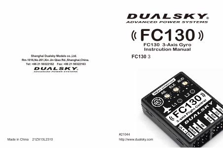
#21044Made in China 21ZX13L2310
Shanghai Dualsky Models co.,Ltd. Rm.1016,No.201,Xin Jin Qiao Rd.,Shanghai,China.
Tel: +86 21 50322162 Fax: +86 21 50322163
FC130 3轴飞机陀螺仪使用说明书
FC130FC130 3-Axis Gyro Instrcution Manual
http://www.dualsky.com
- 2 -- 1 -
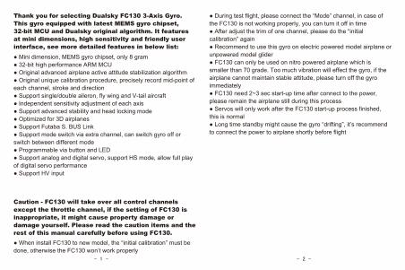
Thank you for selecting Dualsky FC130 3-Axis Gyro. This gyro equipped with latest MEMS gyro chipset, 32-bit MCU and Dualsky original algorithm. It features at mini dimensions, high sensitivity and friendly user interface, see more detailed features in below list:● Mini dimension, MEMS gyro chipset, only 8 gram● 32-bit high performance ARM MCU● Original advanced airplane active attitude stabilization algorithm● Original unique calibration procedure, precisely record mid-point of each channel, stroke and direction● Support single/double aileron, fly wing and V-tail aircraft● Independent sensitivity adjustment of each axis● Support advanced stability and head locking mode● Optimized for 3D airplanes● Support Futaba S. BUS Link● Support mode switch via extra channel, can switch gyro off or switch between different mode● Programmable via button and LED● Support analog and digital servo, support HS mode, allow full play of digital servo performance● Support HV input
Caution - FC130 will take over all control channels except the throttle channel, if the setting of FC130 is inappropriate, it might cause property damage or damage yourself. Please read the caution items and the rest of this manual carefully before using FC130.● When install FC130 to new model, the “initial calibration” must be done, otherwise the FC130 won’t work properly
● During test flight, please connect the “Mode” channel, in case of the FC130 is not working properly, you can turn it off in time● After adjust the trim of one channel, please do the “initial calibration” again● Recommend to use this gyro on electric powered model airplane or unpowered model glider● FC130 can only be used on nitro powered airplane which is smaller than 70 grade. Too much vibration will effect the gyro, if the airplane cannot maintain stable attitude, please turn off the gyro immediately● FC130 need 2~3 sec start-up time after connect to the power, please remain the airplane still during this process● Servos will only work after the FC130 start-up process finished, this is normal● Long time standby might cause the gyro “drifting”, it’s recommend to connect the power to airplane shortly before flight
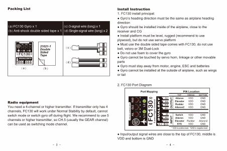
Packing List Install Instruction1. FC130 install principal:
- 4 -- 3 -
Radio equipmentYou need a 4-channel or higher transmitter. If transmitter only has 4 channels, FC130 will work under Normal Stability by default, cannot switch mode or switch gyro off during flight. We recommend to use 5 channels or higher transmitter, so CH.5 (usually the GEAR channel) can be used as switching mode channel.
(c)
(a)
(d)
(b)
21021-1DoubleSidedTape
(a)FC130 Gyro x 1(b)Anti-shock double sided tape x 1
(c)3-signal wire (long) x 1(d)Single-signal wire (long) x 2
● Gyro’s heading direction must be the same as airplane heading direction● Gyro should be installed inside of the airplane, close to the receiver and CG● Install platform must be level, rugged (recommend to use plywood), but do not use servo platform● Must use the double sided tape comes with FC130, do not use belt, velcro or 3M Dual-Lock● Do not use foam to cover the gyro● Gyro cannot be touched by servo horn, linkage or other movable parts● Gyro must stay away from motor, engine, ESC and batteries● Gyro cannot be installed at the outside of airplane, such as wings or tail
2. FC130 Port Diagram
Port Mapping PIN Location
OU
TPU
TIN
PUT
TOP MIDDLE BOTTOMAileronElevatorRudderAileron2
VDDVDDVDDVDD
GNDGNDGNDGND
SwitchAileronElevator
SYS
VDDVDD
RudderVDD
GNDGND
Aileron2GND
* VDD is positive lead. *GND is negative lead.
● Input/output signal wires are close to the top of FC130, middle is VDD and bottom is GND
- 6 -- 5 -
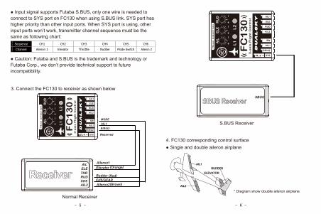
● Input signal supports Futaba S.BUS, only one wire is needed to connect to SYS port on FC130 when using S.BUS link. SYS port has higher priority than other input ports. When SYS port is using, other input ports won’t work, transmitter channel sequence must be the same as following chart:
Sequence CH1 CH2 CH3 CH4 CH5
Channel Aileron 1 Elevator Throttle Rudder Mode Switch
● Caution: Futaba and S.BUS is the trademark and technology or Futaba Corp., we don’t provide technical support to future incompatibility.
3. Connect the FC130 to receiver as shown below
Normal Receiver
MODEAIL1E/R/A2
CH5/GEAR Rudder
Aileron1Elevator
Reserved
AILELETHRRUDCH5
S.BUS Receiver
SBUS
4. FC130 corresponding control surface● Single and double aileron airplane
RUDDERELEVATOR
AIL2
AIL1
* Diagram show double aileron airplane
Aileron2
CH6
Aileron 2
AIL2
(Orange)
(Red)
(Brown)
- 8 -- 7 -
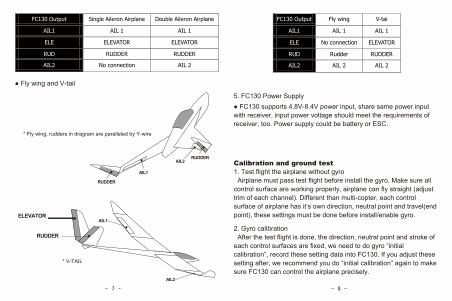
FC130 Output Single Aileron Airplane Double Aileron Airplane
AIL1 AIL 1 AIL 1
ELE ELEVATOR ELEVATOR
RUD RUDDER RUDDER
AIL2 No connection AIL 2
● Fly wing and V-tail
RUDDER
AIL1
AIL2RUDDER
* Fly wing, rudders in dragram are paralleled by Y-wire
ELEVATOR
RUDDER
FC130 Output Fly wing V-tai
AIL1 AIL 1 AIL 1
ELE No connection ELEVATOR
RUD Rudder RUDDER
AIL2 AIL 2 AIL 2
5. FC130 Power Supply● FC130 supports 4.8V-8.4V power input, share same power input with receiver, input power voltage should meet the requirements of receiver, too. Power supply could be battery or ESC.
Calibration and ground test1. Test flight the airplane without gyro Airplane must pass test flight before install the gyro. Make sure all control surface are working properly, airplane can fly straight (adjust trim of each channel). Different than multi-copter, each control surface of airplane has it’s own direction, neutral point and travel(end point), these settings must be done before install/enable gyro.
2. Gyro calibration After the test flight is done, the direction, neutral point and stroke of each control surfaces are fixed, we need to do gyro “initial calibration”, record these setting data into FC130. If you adjust these setting after, we recommend you do “initial calibration” again to make sure FC130 can control the airplane precisely.
AIL1
AIL2
* V-TAIL
- 9 - - 10 -
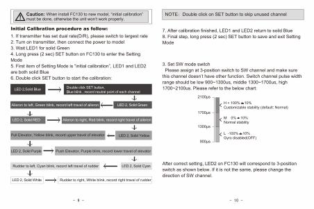
Initial Calibration procedure as follow:1. If transmitter has set dual rate(D/R), please switch to largest rate2. Turn on transmitter, then connect the power to model3. Wait LED1 for solid Green4. Long press (2 sec) SET button on FC130 to enter the Setting Mode5. First item of Setting Mode is “initial calibration”, LED1 and LED2 are both solid Blue6. Double click SET button to start the calibration:
Aileron to left, Green blink, record left travel of aileron
LED 2,Solid Blue Double click SET button, Blue blink , record neutral point of each channel
LED 2, Solid Green
LED 2, Solid RED Aileron to right, Red blink, record right travel of aileron
LED 2, Solid YellowPull Elevator, Yellow blink, record upper travel of elevator
LED 2, Solid Purple Push Elevator, Purple blink, record lower travel of elevator
LED 2, Solid CyanRudder to left, Cyan blink, record left travel of rudder
LED 2, Solid White Rudder to right, White blink, record right travel of rudder
7. After calibration finished, LED1 and LED2 return to soild Blue8. Final step, long press (2 sec) SET button to save and exit Setting Mode
3. Set SW mode switch Please assign at 3-position switch to SW channel and make sure this channel doesn’t have other function. Switch channel pulse width range should be low 900~1300us, middle 1300~1700us, high 1700~2100us. Please refer to the below chart:
1700μs
900μs
2100μs
1300μs
H + 100% + 10%Customizable stability (default: Normal)
M 0% + 10%Normal stability
L -100% + 10%Gyro disabled(OFF)
After correct setting, LED2 on FC130 will correspond to 3-position switch as shown below. If it is not the same, please change the direction of SW channel.
Caution: When install FC130 to new model, “initial calibration” must be done, otherwise the unit won’t work properly.! NOTE:Double click on SET button to skip unused channel
4. Ground Test● After each “initial calibration”, please do a ground test● Test if the SW mode switch is working properly. Do not turn on the motor/engine, toggle the SW mode switch on the transmitter to middle or high position (Low is gyro off), LED2 will turn Green for 0.5 sec, now FC130 is under Normal Stability.
- 12 -
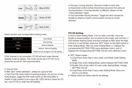
FC130 Setting● How to enter Setting Mode: Turn on radio controller, move the throttle to lowest position; turn on power to the model, wait until the L1 LED finishes flashing Green and then changes to RED (Now the flight control is in Lock Mode); press the “SET” button on the flight control to enter Setting Mode. After you enter Setting Mode, L1 displays the corresponding SETTING ITEM menu attributes (color), and L2 displays the corresponding SETTING VALUE menu attribute (color).
L2 Blue (0.5S)Low
L2 Red (0.5S)High
L2 Green (0.5S)Middle
Switch position and corresponded working mode:
Switch position Gyro Mode
Low Not working
Middle Normal Stability
High Default - Normal Stability
Mode can be changed in FC130 setting
If SW channel is not connected, FC130 will work under Normal Stability mode by default. This mode can be set in FC130, but it cannot be turned off. (Not recommended)
● Test gyro moving direction. Move the model on each axis, corresponded control surface should have excursion the same as moving direction. If moving direction is different, please run the “initial calibration” again.● Test transmitter moving direction. Toggle the stick (except the throttle) to observe if each control surface moving at correct direction.
● “SET” Button usage: 1) Long Press (more than 2 sec) under Lock Mode: enter Setting Mode 2) Single Click under Setting Mode: switch between SETTING ITEM 3) Double Click (finish within 0.5 sec) under Setting Mode: change SETTING VALUE 4) Long Press (more than 2 sec) under Setting Mode: Save and Quit to Lock Mode● Please check the below chart for all settings
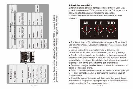
Adjust the sensitivityDifferent airplane, different flight speed need different Gain. Via 3 potentiometers on the FC130, you can adjust the Gain of each axis easily. Rotate clockwise will increase the gain, rotate count-clockwise will decrease the Gain. Please refer to below diagram.
● C
autio
n: S
ome
setti
ngs
will
take
effe
ct a
fter t
he F
C13
0 is
rest
arte
d. C
ut th
e po
wer
to th
e FC
130
and
reco
nnec
t afte
r 5 s
econ
ds to
app
ly th
e ne
w s
ettin
gs
- 14 -- 13 -
AIL ELE RUD
+ - + - + -
● The default Gain of FC130 is suitable for 50 grade EP airplane, if use on small airplane, Gain might be too low. Please increase Gain accordingly.● Correct Gain setting requires test flight to determine, it’s recommend to use more conservative Gain (low) during test flight.● At safety altitude, accelerate the airplane to its maximum speed, observe if there are oscillation in Pitch, Roll and Yaw axis. If there are oscillation, it indicates the gain is too high, please slow down the airplane or turn off the gyro, adjust the gain after landing.● Please do not adjust the Gain too much a time, it’s recommend to adjust 5-10 degrees a time.● Gain too low will cause the airplane become blunt, a basic principal is ---- Gain cannot be too low to decrease the maximum travel of control surface.● Some 3D movements require high Gain under low speed, these kind of Gain is not good for high speed flight. It’s recommend to use switch to control the Gyro compensate timing.
Cal
ibra
tion
Proc
edur
e
Airp
lane
Typ
e
Blu
e
Red
Yello
w
Max
imum
Rol
ling
Velo
city
L1Se
tting
Item
Setti
ng V
alue
Blu
eG
reen
200H
z26
6Hz
400H
z
L2
Red
Yello
w
Purp
le
Fact
ory
Res
etW
hite
Cya
n
Inst
all D
irect
ion
Serv
o Ty
pe(P
WM
)
Dou
ble
clic
k to
sta
rt th
e pr
oced
ure
Nor
mal
Sta
bilit
yA
ilero
n - n
orm
alE
leva
tor -
nor
mal
Rud
der -
nor
mal
Adva
nced
Sta
bilit
yA
ilero
n - h
eadi
ng lo
cked
Ele
vato
r - h
eadi
ng lo
cked
Rud
der -
nor
mal
3D S
tabi
lity
Aile
ron
- hea
ding
lock
edE
leva
tor -
hea
ding
lock
edR
udde
r - h
eadi
ng lo
cked
360d
ps54
0dps
720d
ps
Nor
mal
Fly
Win
gV-
tail
Dou
ble
Clic
kto
Res
et
Face
Up
Face
Dow
nFa
ce L
eft
Face
Rig
ht
Ana
log(
50H
Z)
Flyi
ng M
ode
Gre
en
Dig
ital(1
20H
Z)D
igita
l(200
HZ)
FC130 3轴飞机陀螺仪使用说明书
FC130
上海双天模型有限公司Tel: +86 21 50322162 Fax: +86 21 50322163#21044
- 16 -- 15 -
- 18 -- 17 -
感谢使用双天公司出品的FC130-模型飞机用3轴陀螺仪。陀螺采用最新的MEMS陀螺仪芯片,32位高性能处理器和双天自主研发的姿态算法。它具备体积小,灵敏度高和容易使用等特点,更多特点见下表:
● 超小尺寸设计,使用MEMS陀螺仪芯片,仅8克
● 32位高性能ARM内核处理器
● 自主研发高级飞机姿态稳定算法
● 独创的通道校准程序,精确记录个通道中立点,行程以
及方向
● 支持单/双副翼,飞翼和V型尾翼飞行器
● 可独立调整3轴的感度
● 支持增稳和锁定(heading)两种飞行模式
● 针对3D飞机模型做了优化
● 支持Futaba S.BUS link
● 支持模式切换通道,作为陀螺仪开关及模式切换
● 可通过按键和LED灯编程
● 支持模拟和数字舵机,具备HS模式,可充分发挥数字舵
机效能
● 支持高电压HV输入
注意事项 – FC130会接管除油门外的主要控制通道,如果设定不当会造成模型损失甚至人身伤害。请在使用本产品前仔细阅读注意事项和余下章节。
● 当FC130被安装到新的模型上时,必须执行“陀螺仪校
准程序”,否则将无法正常工作。
● 新模型试飞,请务必连接Mode通道,以便FC130工作不
正常时关闭陀螺仪功能。
● 当你调整过某通道的微调,行程或方向,请重新执行“
陀螺仪校准程序”。
● 推荐在电动飞机或无动力滑翔机上使用此系统。
● FC130只能用在70级以下油动飞机上。过大的震动可能
会影响系统的工作,如果模型姿态无法稳定,请及时关闭
陀螺仪功能并停止使用。
● 陀螺仪每次上电都有2-3秒初始化过程,请避免这个过
程中模型的晃动。
● 陀螺仪初始化结束后,舵机才会工作,这是正常情况。
● 长时间待机,陀螺仪会漂移,建议飞行前才接通模型电
源。
- 20 -- 19 -
物品清单
(c)
(a)
(d)
(b)
21021-1DoubleSidedTape双面胶
(a)FC130平衡仪 x 1(b)减震双面胶 x 1
(c)三信号排线(长) x 1(d)单信号排线(长)x 2
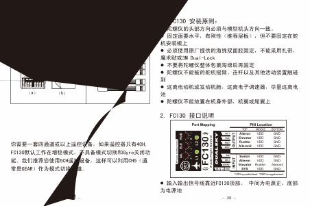
2. FC130 接口说明
Port Mapping PIN Location
OU
TPU
TIN
PUT
TOP MIDDLE BOTTOMAileronElevatorRudderAileron2
VDDVDDVDDVDD
GNDGNDGNDGND
SwitchAileronElevator
SYS
VDDVDD
RudderVDD
GNDGND
Aileron2GND
* VDD is positive lead. *GND is negative lead.
● 输入输出信号线靠近FC130顶部, 中间为电源正,底部
为电源地
遥控设备你需要一套四通道或以上遥控设备,如果遥控器只有4CH,
FC130默认工作在增稳模式,不具备模式切换和Gyro关闭功
能。我们推荐您使用5CH遥控设备,这样可以利用CH5(通
常是GEAR)作为模式切换通道。
安装指南1. FC130 安装原则:● 陀螺仪的头部方向必须与模型机头方向一致。● 固定面要水平,有刚性(推荐层板),但不要固定在舵
机安装板上● 必须使用原厂提供的海绵双面胶固定,不能采用扎带,
魔术贴或3M Dual-Lock● 不要将陀螺仪整体包裹海绵后再固定● 陀螺仪不能被的舵机摇臂、连杆以及其他活动装置触碰
到● 远离电动机或发动机舱,远离电子调速器,尽量远离电
池● 陀螺仪不能放置在机身外部,机翼或尾翼上
- 22 -- 21 -
AILELETHRRUDCH5
SBUS
RUDDERELEVATOR
AIL2
AIL1
* 图示为双副翼飞机
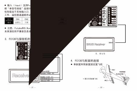
● 输入(Input)支持Futaba S.Bus, 这是只需要采用一
根“单信号排线”连接SYS口和接收机S.Bus接口。SYS接口
优先级高于其他输入口。当采用SYS输入时,其他输入口不
工作,遥控器通道顺序必须同下表:
顺序 CH1 CH2 CH3 CH4 CH5
通道 副翼 1 升降 油门 方向 模式开关
● 注意:Futaba和S.Bus双叶公司商标及技术,我们不对
未来潜在的不兼容负责或提供技术支持。
3. FC130与接收机的连接。如下图所示
普通接收机
S.BUS接收机
4. FC130与舵面的连接● 单副翼和双副翼固定翼飞机
CH6
副翼2
MODEAIL1E/R/A2
CH5/GEAR Rudder
Aileron1Elevator
Reserved
Aileron2AIL2
副翼1
升降舵(橙)
方向舵(红)
模式开关
副翼2(棕)
- 24 -- 23 -
RUDDER
AIL1
AIL2RUDDER
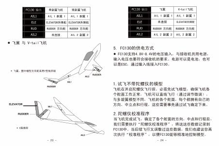
校准与地面调试1.试飞不带陀螺仪的模型飞机在开启陀螺仪飞行前,必需先试飞模型,确保飞机各
个舵面工作正常,飞机可以直线飞行(通过调节微调)。
与多旋翼模型不同,飞机的各个舵面,每个都拥有自己的
方向,中立点和行程,这些需要事先通过试飞确定下来。
FC130 输出 单副翼飞机 双副翼飞机
AIL1 AIL 1 副翼 1 AIL 1 副翼 1
ELE ELEVATOR升降舵
RUD RUDDER 方向舵 RUDDER 方向舵
AIL2 未连接 AIL 2 副翼 2
● 飞翼 与 V-tail飞机
* 飞翼,图中模型方向舵采用Y型线并联
* V尾模型
FC130 输出 飞翼 V-tail飞机
AIL1 AIL 1 副翼 1
ELE 未连接
RUD
AIL2
5. FC130的供电方式● FC130支持4.8V-8.4V的电压输入,与接收机共用电源,
输入电压也要符合接收机的要求。电源可以是电池,也可
以是ESC,通过输入线接入FC130。
2.陀螺仪校准程序当飞机完成试飞,确定了各个舵面的方向,中点和行程后,
我们需要执行“陀螺仪校准程序”,将这这些数据记录到
FC130中。当后续飞行又调整过这些数据,我们也建议你再
次执行“校准程序”,以便FC130能够精准地控制模型。
ELEVATOR
RUDDER
AIL1
AIL2
ELEVATOR升降舵
AIL 1 副翼 1
ELEVATOR升降舵
RUDDER 方向舵 RUDDER 方向舵
AIL 2 副翼 2 AIL 2 副翼 2
- 26 -- 25 -
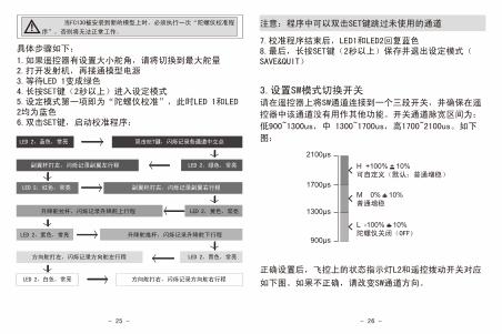
具体步骤如下:
1.如果遥控器有设置大小舵角,请将切换到最大舵量2.打开发射机,再接通模型电源3.等待LED 1变成绿色4.长按SET键(2秒以上)进入设定模式5.设定模式第一项即为“陀螺仪校准”,此时LED 1和LED 2均为蓝色6.双击SET键,启动校准程序:
副翼杆打左,闪烁记录副翼左行程
LED 2,蓝色,常亮 双击SET键,闪烁记录各通道中立点
LED 2,绿色,常亮
LED 2,红色,常亮 副翼杆打右,闪烁记录副翼右行程
LED 2,黄色,常亮升降舵拉杆,闪烁记录升降舵上行程
LED 2,紫色,常亮 升降舵推杆,闪烁记录升降舵下行程
LED 2,青色,常亮方向舵打左,闪烁记录方向舵左行程
LED 2,白色,常亮 方向舵打右,闪烁记录方向舵右行程
7.校准程序结束后,LED1和LED2回复蓝色8.最后,长按SET键(2秒以上)保存并退出设定模式(SAVE&QUIT)
3.设置SW模式切换开关请在遥控器上将SW通道连接到一个三段开关,并确保在遥
控器中该通道没有用作其他功能。开关通道脉宽区间为:
低900~1300us,中 1300~1700us,高1700~2100us。如下
图:
正确设置后,飞控上的状态指示灯L2和遥控拨动开关对应
如下图。如果不正确,请改变SW通道方向。
1700μs
900μs
2100μs
1300μs
H +100% + 10%可自定义(默认:普通增稳)
M 0% + 10%普通增稳
L -100% + 10%陀螺仪关闭(OFF)
! 注意:当FC130被安装到新的模型上时,必须执行一次“陀螺仪校准程
序”,否则将无法正常工作。注意:程序中可以双击SET键跳过未使用的通道
FC130 设定● 如何进入设定模式:打开遥控器,油门收至最低,接通
飞机的电源,等待飞控L1绿灯闪烁结束,长按飞控上的
“SET”按钮(2S)进入设定模式。此时,L1的颜色指示设
定项目,L2的颜色指示该设定项当前设定值。
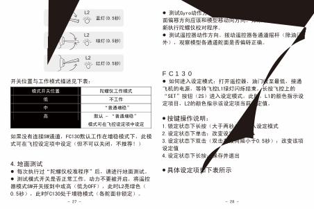
L2 蓝灯(0.5秒)低
L2
L2
开关位置与工作模式描述见下表:
如果没有连接SW通道,FC130默认工作在增稳模式下,此模
式可在飞控设定项中设定(但不可以关闭,不推荐!)
● 按键操作说明:1.锁定状态下长按(大于两秒):进入设定模式
2.设定状态下单击:改变设定项
3.设定状态下双击(双击有效间隔小于0.5秒):改变该项
设定值
4.设定状态下长按:保存并退出
● 具体设定项如下表所示
模式开关位置 陀螺仪工作模式
低 不工作
中 “普通增稳”
高 默认 – “普通增稳”
模式可在飞控设定项中设定
4.地面测试● 每次执行过“陀螺仪校准程序”后,请进行地面测试。● 测试模式开关是否正常工作。动力不要被开启,将遥控
器模式SW开关拨到中或高(低为OFF),此时L2亮绿色(
0.5秒),此时FC130处于增稳模式(各舵面非锁定)。
中
高
绿灯(0.5秒)
红灯(0.5秒)
- 28 -- 27 -
● 测试Gyro动作方向。在各个轴向上移动模型,对应的舵
面偏移方向应该和模型移动同方向。如果不同方向,请重
新执行陀螺仪校对程序。● 测试遥控器动作方向。拨动遥控器各通道摇杆(除油门
外),观察模型各通道舵面是否偏转正确。
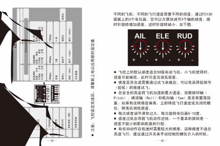
调节感度不同的飞机,不同的飞行速度需要不同的感度。通过FC130
面板上的3个电位器,您可以方便地调节3个轴的感度。顺
时针旋转增加感度,逆时针旋转减小。如下图。
AIL ELE RUD
+ - + - + -
● 注意:飞控设定完成后,请重新上电以应
用新的设定值
● 飞控上的默认感度适合50级电动飞机,小飞机使用时,
感度可能偏低。此时可适当调高感度。● 感度是否合适需要通过试飞来确定,可以先采用较保守
(较低)的感度试飞。● 在安全的高度将飞机加速到最大速度,观察俯仰轴(
Pitch)、横滚轴(Roll)和航向轴(Yaw)是否有震荡现
象。如果有说明感度偏高,立即降低飞行速度或关闭陀螺
仪,降落后调低感度。● 每次感度调节请勿过大,每次旋转电位器5-10度。● 感度过低会导致飞机动作迟钝,一个基本的原则是 –
感度不能小到影响舵面的行程。● 有些3D动作在低速时需要较大的感度,这种感度不适合
高速飞行,建议通过开关来手动控制陀螺仪介入的时机。
- 30 -- 29 -
蓝色
L1设
定选
项
200H
z26
6Hz
400H
z
L2
普通增稳
副翼 -
正常
升降舵 -
正常
方向舵 -
正常
高级增稳
副翼 -
锁定
升降舵 -
锁定
方向舵 -
正常
3D 增稳
副翼 -
锁定
升降舵 -
锁定
方向舵 -
锁定
360d
ps54
0dps
720d
ps
飞翼
V-尾
双击重置
模拟(50HZ)
绿色
红色
紫色
黄色
青色
白色
飞行模式
恢复预设值
校准程序
飞机翻滚速率
飞机类型
安装方向
设定
值蓝
色绿
色红
色黄
色
双击启动程序
普通
面朝上
面朝下
面朝右
面朝左
舵机类型(PWM)
数字(120HZ)
数字(200HZ)