Embed Size (px)
Citation preview
Shape-Controlled Colloidal Interactionsin Nematic Liquid Crystals
Clayton P. Lapointe,1,2 Thomas G. Mason,2 Ivan I. Smalyukh1*
Robust control over the positions, orientations, and assembly of nonspherical colloids may aid in thecreation of new types of structured composite materials that are important from both technologicaland fundamental standpoints. With the use of lithographically fabricated equilateral polygonal platelets,we demonstrate that colloidal interactions and self-assembly in anisotropic nematic fluids can beeffectively tailored via control over the particles’ shapes. The particles disturb the uniform alignment ofthe surrounding nematic host, resulting in both a distinct equilibrium alignment and highlydirectional pair interactions. Interparticle forces between polygonal platelets exhibit either dipolar orquadrupolar symmetries, depending on whether their number of sides is odd or even, and drive theassembly of a number of ensuing self-assembled colloidal structures.
Self-assembly of micrometer- and nanometer-
scale colloidal particles into ordered struc-
tures is of wide-ranging interest for both
fundamental science and technological appli-
cations (1). In isotropic liquids such as water,
the electrostatic and entropic forces that drive
the assembly of spherical colloids are typically
isotropic, limiting the overall landscape of pos-
sible structures. Concentrated suspensions of
monodisperse spherical particles are an impor-
tant example; these can form three-dimensional
(3D) colloidal crystals that are markedly similar
to their atomic counterparts. However, colloidal
crystals formed in this fashion are restricted to
lattices with high packing fractions, such as
hexagonal close-packed or face-centered cubic
(2). The generation of anisotropic interactions is
necessary to increase the complexity and diver-
sity of colloidal architectures formed by such
interactions (3–6). Oriented assemblies of parti-
cles can be produced by means such as nonuni-
form patterning of their surfaces (3), anisotropic
deposition of colloids onto solid substrates (4),
or application of external fields (5). Alterna-
tively, introducing anisotropy directly into a sol-
vent by using a nematic liquid crystal (NLC),
one can engender anisotropic interaction forces
between colloids that are not present in ordi-
nary fluids (7). NLCs are composed of rod-
shaped molecules with long molecular axes
aligned along a common direction (8). The local
average molecular orientation is often repre-
sented by a unit vector n with inversion sym-
metry n ≡ –n, referred to as the director. The
dependence of n as a function of spatial posi-
tion r is described with a director field n(r).
Anisotropic molecular interactions at NLC sur-
faces, known as surface anchoring, result in a
preferential alignment and boundary conditions
for n(r). Colloids immersed in NLCs deform the
surrounding director field because of this surface
anchoring and induce point or line defects [re-
gions where n(r) is discontinuous] in the nematic
bulk (Fig. 1, A and B) or at the nematic-particle
interface (Fig. 1C), unless the surface anchoring
is weak or the particles are small (supporting
online material fig. S1) (9). The particles and
accompanying defects introduce long-range
gradients in n(r) that depend on particle size
(9), type and strength of surface anchoring
(10), confinement (11, 12), and external fields
(13). The elastic energy due to these gradients
depends on the particles’ relative positions and
gives rise to interactions mediated by elasticity.
Even for spherical particles in NLCs (Fig. 1, A
to C), elastic interactions are highly anisotropic
and can lead to a host of self-assembled struc-
tures ranging from linear and branched chains to
2D crystals (7, 9–16). Reminiscent of electrostatic
interactions exhibited by charge distributions,
elastic colloidal interactions bear qualitatively
different symmetries that mimic the dipolar (Fig.
1A) or quadrupolar (Fig. 1, B and C) symmetries
of n(r) around isolated particles.
We demonstrate that altering the shapes of
particles can lead to marked changes in the
symmetry of their elastic interactions and the
resulting colloidal assemblies in NLCs. Optical
polarizing microscopy (PM) and fluorescence
confocal polarizing microscopy (FCPM) show
1Department of Physics, Renewable and Sustainable EnergyInstitute, and Liquid Crystals Materials Research Center,University of Colorado at Boulder, Boulder, CO 80309, USA.2Department of Chemistry and Biochemistry, Department ofPhysics and Astronomy, and California NanoSystems Institute,University of California at Los Angeles, Los Angeles, CA 90095,USA.
*To whom correspondence should be addressed. E-mail:[email protected]
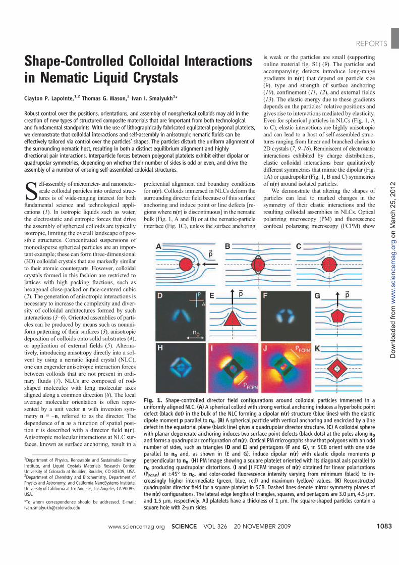
Fig. 1. Shape-controlled director field configurations around colloidal particles immersed in auniformly aligned NLC. (A) A spherical colloid with strong vertical anchoring induces a hyperbolic pointdefect (black dot) in the bulk of the NLC forming a dipolar n(r) structure (blue lines) with the elasticdipole moment p parallel to n0. (B) A spherical particle with vertical anchoring and encircled by a linedefect in the equatorial plane (black line) gives a quadrupolar director structure. (C) A colloidal spherewith planar degenerate anchoring induces two surface point defects (black dots) at the poles along n0and forms a quadrupolar configuration of n(r). Optical PMmicrographs show that polygons with an oddnumber of sides, such as triangles (D and E) and pentagons (F and G), in 5CB orient with one sideparallel to n0 and, as shown in (E and G), induce dipolar n(r) with elastic dipole moments pperpendicular to n0. (H) PM image showing a square platelet oriented with its diagonal axis parallel ton0 producing quadrupolar distortions. (I and J) FCPM images of n(r) obtained for linear polarizations(PFCPM) at T45° to n0, and color-coded fluorescence intensity varying from minimum (black) to in-creasingly higher intermediate (green, blue, red) and maximum (yellow) values. (K) Reconstructedquadrupolar director field for a square platelet in 5CB. Dashed lines denote mirror symmetry planes ofthe n(r) configurations. The lateral edge lengths of triangles, squares, and pentagons are 3.0 mm, 4.5 mm,and 1.5 mm, respectively. All platelets have a thickness of 1 mm. The square-shaped particles contain asquare hole with 2-mm sides.
www.sciencemag.org SCIENCE VOL 326 20 NOVEMBER 2009 1083
REPORTS
on M
arc
h 2
5,
2012
ww
w.s
cie
ncem
ag.o
rgD
ow
nlo
aded f
rom
that platelet colloids with equilateral polygonal
shapes exhibit well-defined alignment and elastic
deformations of n(r) that have either dipolar or
quadrupolar symmetry. Colloidal polygons with
an odd number of sides form elastic dipoles,
whereas even-sided particles form elastic quadru-
poles. Using model polygonal platelets shaped as
triangles, squares, and pentagons, we demon-
strate that their shape dictates the resulting n(r)
symmetry as well as the symmetry of the ensuing
elastic interactions. Particle tracking video mi-
croscopy (17), combined with optical tweezing
of particle pairs, provides direct measurements of
anisotropic interaction forces.
Monodisperse platelet colloids of uniform
thickness and predesigned shapes are fabricated
with the use of photolithography (18). Micron-
sized polygonal colloids of triangular, square,
and pentagonal shapes are produced using an
ultraviolet-sensitive photoresist (SU-8) on Si
wafers (19). After exposure and development,
the particles are released from the wafers into an
organic solvent and transferred into pentylcyano-
biphenyl (5CB), a room temperature NLC. Sample
cells consisting of parallel glass plates separated
by 10- to 60-mm spacers are filled with colloi-
dal dispersions in 5CB by capillary action and
sealed with epoxy. The far-field alignment di-
rection n0 is set by unidirectional rubbing of
the polyimide coated inner surfaces of the cell.
The samples are studied with an inverted op-
tical microscope equipped with a confocal laser
scanning unit and a holographic optical tweezers
system (20) operating at l = 1064 nm. The 3D
structure of n(r) around the colloids is deter-
mined with lateral and vertical resolution of
~0.5 mmwith the use of FCPM (21). For FCPM
observations, 0.01 weight percent of anisotropic
fluorescent dye was dissolved homogeneously
in 5CB (19); at this concentration, the rodlike
dye molecules do not alter the NLC properties
and orient parallel to 5CB molecules so that the
contrast in the fluorescence image arises from
spatial changes in n(r) (21). Imaging and op-
tical tweezing are performed simultaneously
with a 100× oil-immersion objective.
PM images reveal the n(r) deformations
surrounding isolated particles of each type
suspended in aligned 5CB (Fig. 1). When n0 is
oriented along the linear polarization of incident
light, distorted regions where n(r) departs from
n0 alter the polarization state of transmitted light
and appear bright when viewed through the
analyzer. Polygonal platelets always orient with
their larger-area top and bottom surfaces parallel
to n0, suggesting planar degenerate anchoring at
the interface of SU-8 and 5CB. Polygons that
have an odd number of sides (N), such as
triangles and pentagons, orient with one of their
sides along n0, and bright lobes are visible near
their other sides (Fig. 1, D and F). However,
colloids with even N, such as squares, align with
one diagonal axis along n0, and bright regions
appear symmetrically along all outer and inner
edges (Fig. 1H). PM and FCPM textures indicate
the presence of three mirror symmetry planes
of the n(r) deformations, which intersect the
particle’s center of mass: one coplanar with both
n0 and the unit vector v normal to the platelet’s
larger-area faces, a second parallel to the faces,
and a third plane orthogonal to n0. Thus, the n(r)
structure is quadrupolar, as schematically shown
in Fig. 1K, resembling the symmetry of elastic
quadrupoles formed by spherical particles (Fig. 1,
B and C). Further, because the strongest FCPM
signal corresponds to regions where n(r) is par-
allel to the linear FCPM polarization, the flu-
orescence images in Fig. 1, I and J, demonstrate
that n(r) is indeed quadrupolar and consistent
with surface anchoring of 5CB on SU-8 photo-
resist being degenerate planar (22).
In the case of triangles and pentagons with
odd N, however, the mirror symmetry plane that
is coplanar with both n0 and v is broken so that
the n(r) structure is dipolar (Fig. 1, E and G),
unlike that of other previously studied colloids
promoting planar surface anchoring (15, 23).
Moreover, the elastic dipole moment p is orthog-
onal to n0 (Fig. 1E), in contrast to what is seen
for colloids with vertical surface anchoring and
p parallel to n0 (7, 11, 14, 24), as shown in Fig.
1A. Examples of dipoles that align orthogonally
to field lines are rare but can be formed by
dipolar pairs of line defects in NLCs (19) and
vortex spin configurations in ferromagnets (8).
Similar to a sphere with planar anchoring shown
in Fig. 1C, the shape-dictated dipolar structures
of odd-N platelets do not give rise to point or
line defects in the NLC bulk. The dipolar n(r)
symmetry of odd-N platelets should be stable
with respect to varying particle size and the
strength of surface anchoring at their interfaces
(fig. S1) (19). This is different from the case of
dipoles formed by spherical colloids accom-
panied by bulk point defects (Fig. 1A) observed
only for strong anchoring and for particle sizes
larger than ~1 mm, but not for smaller colloids for
which a quadrupolar n(r) (Fig. 1B) is of lower
energy (9). For odd-N polygonal platelets,
although the magnitude of p decreases with de-
creasing particle size or weakening anchoring
strength (fig. S1), the alignment and dipolar
symmetry should retain down to particle sizes
of ~50 to 100 nm, at which the planar boundary
conditions at the platelet surfaces are expected
to partially relax (19). For N = 5, the magnitude
of p is smaller than that for N = 3 (Fig. 1), and
we expect that it decreases further as N in-
creases and ultimately vanishes in the limit N→
∞, corresponding to a circular disc with quadru-polar n(r) (9).
The director field configurations surrounding
regular polygons (Fig. 1) can be understood
within an elegant theoretical framework that is
built on an analogy with electrostatics (25–27).
Within the one–elastic constant approximation
(19), minimization of theNLC elastic energyUel =
(K/2)∫d3r(∇n)2 [where K is an average Frank
elastic constant, and (∇n)2 = (∇ · n)2 + (∇ × n)2]
leads to Laplace’s equation for n(r). Far from the
particle, deviations from n0 are small, and n(r)
can be expanded in a multipole series contain-
ing elastic monopole, dipole, and quadrupole
terms that decay with distance r as 1/r, 1/r3, and
1/r5, respectively. The predicted absence of an
elastic monopole, when no external torque is
present (25), is consistent with the observed di-
polar symmetry of n(r), as well as the equi-
librium orientation of polygons with odd N. For
example, n(r) would have no planes of mirror
symmetry for a triangle or pentagon oriented so
that all edges are neither parallel nor perpendic-
ular to n0. Consequently, an elastic torque would
be present, and the system would not be in me-
chanical equilibrium. There are two possible ori-
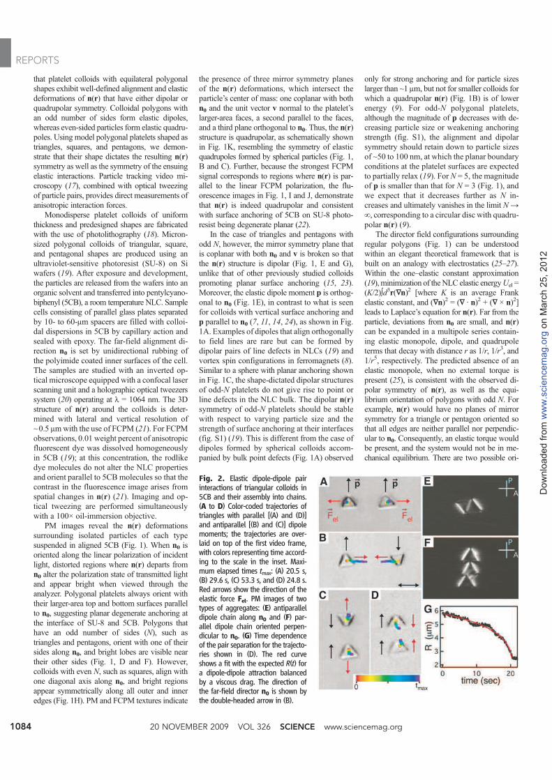
Fig. 2. Elastic dipole-dipole pairinteractions of triangular colloids in5CB and their assembly into chains.(A to D) Color-coded trajectories oftriangles with parallel [(A) and (D)]and antiparallel [(B) and (C)] dipolemoments; the trajectories are over-laid on top of the first video frame,with colors representing time accord-ing to the scale in the inset. Maxi-mum elapsed times tmax: (A) 20.5 s,(B) 29.6 s, (C) 53.3 s, and (D) 24.8 s.Red arrows show the direction of theelastic force Fel. PM images of twotypes of aggregates: (E) antiparalleldipole chain along n0 and (F) par-allel dipole chain oriented perpen-dicular to n0. (G) Time dependenceof the pair separation for the trajecto-ries shown in (D). The red curveshows a fit with the expected R(t) fora dipole-dipole attraction balancedby a viscous drag. The direction ofthe far-field director n0 is shown bythe double-headed arrow in (B).
20 NOVEMBER 2009 VOL 326 SCIENCE www.sciencemag.org1084
REPORTS
on M
arc
h 2
5,
2012
ww
w.s
cie
ncem
ag.o
rgD
ow
nlo
aded f
rom
entations for a triangle or a pentagon with ensu-
ing n(r) having at least two planes of mirror
symmetry: (i) one with a side along n0 giving an
elastic dipole with p perpendicular to n0 and (ii)
another with a side oriented perpendicular to n0(in this case, pwould be parallel to n0). Evidently,
the former has lower elastic energy because this is
the equilibrium orientation observed in the exper-
iments. The alignment of colloidal polygons with
even N, such as square-shaped particles, can be
understood in a similar fashion. Orientations for
which neither of the diagonals are parallel to n0would give rise to an elastic torque and are un-
stable. When the sample is heated into the iso-
tropic phase, no preferred orientation is observed
(fig. S2), confirming the elastic nature of the align-
ment of polygons in the nematic phase. Further-
more, observations during multiple heating and
cooling cycles show that different sides (oddN )
and diagonals (even N ) can align along n0 each
time the sample is quenched into the nematic
phase, demonstrating that there is no preference
in the selection of these sides or diagonals.
Although the orientations of the polygonal
edges are constrained relative to n0, a platelet’s
surface normal v is free to rotate about n0 in the
bulk of a ≈60-mm-thick NLC cell, indicating that
the elastic energy is independent of such rotations
(28). Confinement to cells of thickness compa-
rable to the lateral size of platelets (≈10 mm)
inhibits rotations about n0, and the platelike
colloids orient parallel to the cell substrates to
minimize the elastic energy due to the planar
anchoring at the top and bottom surfaces of the
colloids. To explore the directionality and strength
of anisotropic elastic-pair interactions, we control
the initial positions and orientations of particles
with the use of optical tweezers (11, 12, 15) and
then track their motion using video microscopy
after release from the laser traps. When the center-
to-center separation vector R for two triangles is
along n0, elastic repulsion occurs for parallel
dipoles (Fig. 2A), whereas attraction takes place
for antiparallel dipoles (Fig. 2B). The opposite is
true for situations when R is perpendicular to n0;
antiparallel dipoles repel (Fig. 2C) and parallel
dipoles attract (Fig. 2D). Two types of self-
assembled chainlike aggregates are observed: (i)
antiparallel dipole chains in which the triangles
aggregate along n0 (Fig. 2E) and (ii) chains
perpendicular to n0 consisting of parallel dipoles
(Fig. 2F). Chaining of triangular colloids per-
pendicular to n0 is a consequence of the dipoles’
alignment orthogonal to n0. The dipolar nature of
the elastic interaction is further evidenced by
the time dependence of particle separation R(t)
for a pair of triangles aggregating along n0 (Fig.
2G). Because the system is highly overdamped
(Reynolds number << 1), inertial forces are neg-
ligible and the elastic force Fel is balanced by a
viscous Stokes drag Fdrag = –zdR/dt, where z is
a drag coefficient, and dR/dt is the time-derivative
of the particle separation R(t). For an elastic
dipolar force Fel = –kd/R4 (where kd is a constant
that depends on K and the geometry and size of
the particle), integration of the equation of mo-
tion Fel + Fdrag ≈ 0 yields R(t) = (R05– 5adt)
1/5,
where ad = kd/z, and R0 is the initial separation at
time t = 0 when particles are released from the
traps. R(t) fits the data well with one adjustable
parameter ad = 63.1 T 0.5 mm5/s (red curve in
Fig. 2G). Using an estimate of the drag coefficient
z ~ (2 to 4) × 10−6 kg/s (29) and the maximum
relative velocity dR/dt ≈ 1 mm/s determined from
the data in Fig. 2G, one obtains a maximum
attractive elastic force of 2 to 4 pN near contact
at R ≈ 2.6 mm. This force and the corresponding
binding energy ≈5 × 10⁻¹⁸ J (≈1200kBT, where
kB is Boltzmann’s constant) for a pair of triangles
are comparable to those measured for spherical
colloids of similar size (11, 12, 15).
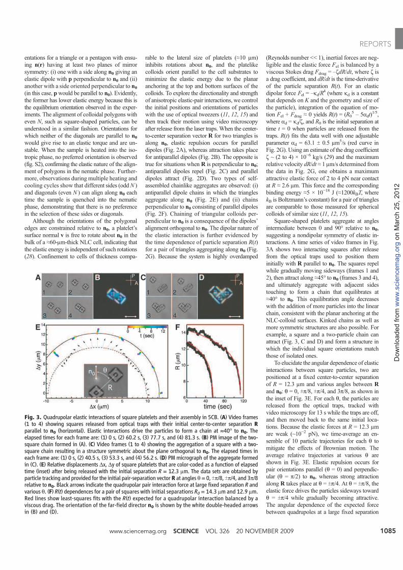
Square-shaped platelets aggregate at angles
intermediate between 0 and 90° relative to n0,
suggesting a nondipolar symmetry of elastic in-
teractions. A time series of video frames in Fig.
3A shows two interacting squares after release
from the optical traps used to position them
initially with R parallel to n0. The squares repel
while gradually moving sideways (frames 1 and
2), then attract along ≈45° to n0 (frames 3 and 4),
and ultimately aggregate with adjacent sides
touching to form a chain that equilibrates at
≈40° to n0. This equilibration angle decreases
with the addition of more particles into the linear
chain, consistent with the planar anchoring at the
NLC-colloid surfaces. Kinked chains as well as
more symmetric structures are also possible. For
example, a square and a two-particle chain can
attract (Fig. 3, C and D) and form a structure in
which the individual square orientations match
those of isolated ones.
To elucidate the angular dependence of elastic
interactions between square particles, two are
positioned at a fixed center-to-center separation
of R = 12.3 mm and various angles between R
and n0: q = 0, Tp/8, Tp/4, and 3p/8, as shown in
the inset of Fig. 3E. For each q, the particles are
released from the optical traps, tracked with
video microscopy for 13 s while the traps are off,
and then moved back to the same initial loca-
tions. Because the elastic forces at R = 12.3 mm
are weak (~10−2 pN), we time-average an en-
semble of 10 particle trajectories for each q to
mitigate the effects of Brownian motion. The
average relative trajectories at various q are
shown in Fig. 3E. Elastic repulsion occurs for
pair orientations parallel (q = 0) and perpendic-
ular (q = p/2) to n0, whereas strong attraction
along R takes place at q = Tp/4. At q = Tp/8, the
elastic force drives the particles sideways toward
q = Tp/4 while gradually becoming attractive.
The angular dependence of the expected force
between quadrupoles at a large fixed separation
Fig. 3. Quadrupolar elastic interactions of square platelets and their assembly in 5CB. (A) Video frames(1 to 4) showing squares released from optical traps with their initial center-to-center separation Rparallel to n0 (horizontal). Elastic interactions drive the particles to form a chain at ≈40° to n0. Theelapsed times for each frame are: (1) 0 s, (2) 60.2 s, (3) 77.7 s, and (4) 81.3 s. (B) PM image of the two-square chain formed in (A). (C) Video frames (1 to 4) showing the aggregation of a square with a two-square chain resulting in a structure symmetric about the plane orthogonal to n0. The elapsed times ineach frame are: (1) 0 s, (2) 40.5 s, (3) 53.3 s, and (4) 56.2 s. (D) PM micrograph of the aggregate formedin (C). (E) Relative displacements Dx, Dy of square platelets that are color-coded as a function of elapsedtime (inset) after being released with the initial separation R = 12.3 mm. The data sets are obtained byparticle tracking and provided for the initial pair-separation vectorR at angles q = 0, Tp/8, Tp/4, and 3p/8relative to n0. Black arrows indicate the quadrupolar pair interaction force at large fixed separation R andvarious q. (F) R(t) dependences for a pair of squares with initial separations R0 = 14.3 mm and 12.9 mm.Red lines show least-squares fits with the R(t) expected for a quadrupolar interaction balanced by aviscous drag. The orientation of the far-field director n0 is shown by the white double-headed arrowsin (B) and (D).
www.sciencemag.org SCIENCE VOL 326 20 NOVEMBER 2009 1085
REPORTS
on M
arc
h 2
5,
2012
ww
w.s
cie
ncem
ag.o
rgD
ow
nlo
aded f
rom
(shown by black arrows in Fig. 3E) (9, 15)
exhibits marked correlation with the measured
displacements, confirming the quadrupolar na-
ture of elastic forces between colloidal squares.
These results imply that the presence of the hole
in a colloidal square and, more generally, other
modifications to the platelet’s topology are
inconsequential to the anisotropy of interactions,
as long as the quadrupolar n(r) symmetry is
preserved.
Quadrupolar forces are expected to decay
with distance as ~R−6 (9, 15). To test if square
platelets interact in thismanner, we havemeasured
the relative positions of two colloidal squares
along q = p/4 from initial separationsR0= 14.3 and
12.9 mm (Fig. 3F). From a balance of a quadru-
polar elastic force Felq = –kq/R6 with a viscous
drag, one obtains the time-dependent particle sep-
aration R(t) = (R07– 7aqt)
1/7, where aq = kq/z .
The two sets of data in Fig. 3F can be fit with R(t)
using only one adjustable parameter aq = (1.6 T
0.1) × 105 mm7/s. Taking the average elastic con-
stant K ≈ 7 pN (30), an effective viscosity h ≈
0.075 Pa⋅s for 5CB, as well as the side length L =
4.5 mm of the platelet, dimensional analysis gives
an estimate of aq ~ KL5/h = 1.7 × 105 mm7/s, in
reasonable agreement with these experiments.
Using a drag coefficient z ≈ 1.9 × 10⁻⁶ kg/s of a
square platelet in 5CB [determined by probing
its diffusive motion with video microscopy (fig.
S3)] and aq = 1.6 × 105 mm7/s, we calculate a max-
imum attractive elastic force of ≈20 pN near con-
tact at R = 4.5 mm and corresponding binding
energy ≈3 × 10⁻¹⁷ J (≈7000kBT ).
In conclusion, elastic colloidal interactions
in NLCs are sensitive to the colloids’ shapes.
Equilibrium director field configurations around
equilateral polygonal colloids exhibit dipolar
symmetry if they have odd N (i.e., triangles or
pentagons) and quadrupolar symmetry if N is
even, giving rise to dipolar and quadrupolar
elastic colloidal interactions, respectively. Elastic
dipole moments of polygonal platelets orient
perpendicular to the far-field director n0. Dipole-
dipole forces drive their assembly into chains
perpendicular to n0 if their dipoles are parallel and
chains along n0 if their dipoles are antiparallel.
Although the symmetry of these highly directional
elastic forces should not change over a broad
range of particle sizes (~50 nm to tens ofmicrons),
the strength can vary substantially. One can envi-
sion the design of such interactions for the as-
sembly of colloidal architectures ranging from
anisotropic aggregates to new types of colloidal
crystals andopticalmetamaterialswithwell-defined
alignment relative to the far-field director.
References and Notes1. G. M. Whitesides, B. Grzybowski, Science 295, 2418
(2002).
2. V. J. Anderson, H. N. Lekkerkerker, Nature 416, 811
(2002).
3. K. Zhao, T. G. Mason, Phys. Rev. Lett. 99, 268301
(2007).
4. K. J. Stebe, E. Lewandowski, M. Ghosh, Science 325, 159
(2009).
5. T. C. Halsey, Science 258, 761 (1992).
6. S. C. Glotzer, Science 306, 419 (2004).
7. P. Poulin, H. Stark, T. C. Lubensky, D. A. Weitz, Science
275, 1770 (1997).
8. P. M. Chaikin, T. C. Lubensky, Principles of Condensed
Matter Physics (Cambridge Univ. Press, Cambridge,
2000).
9. H. Stark, Phys. Rep. 351, 387 (2001).
10. I. I. Smalyukh, A. V. Kachynski, A. N. Kuzmin,
P. N. Prasad, Proc. Natl. Acad. Sci. U.S.A. 103, 18048
(2006).
11. I. Musevic, M. Skarabot, U. Tkalec, M. Ravnik, S. Zumer,
Science 313, 954 (2006).
12. M. Vilfan et al., Phys. Rev. Lett. 101, 237801 (2008).
13. I. Dierking, G. Biddulph, K. Matthews, Phys. Rev. E 73,
011702 (2006).
14. J.-C. Loudet, P. Barois, P. Poulin, Nature 407, 611
(2000).
15. I. I. Smalyukh, O. D. Lavrentovich, A. N. Kuzmin,
A. V. Kachynski, P. N. Prasad, Phys. Rev. Lett. 95,
157801 (2005).
16. A. B. Nych et al., Phys. Rev. Lett. 98, 057801
(2007).
17. J. C. Crocker, D. G. Grier, J. Colloid Interface Sci. 179,
298 (1996).
18. C. J. Hernandez, T. G. Mason, J. Phys. Chem. C 111, 4474
(2007).
19. Materials and methods are available as supporting
material on Science Online.
20. D. G. Grier, Nature 424, 810 (2003).
21. I. I. Smalyukh, S. V. Shiyanovskii, O. D. Lavrentovich,
Chem. Phys. Lett. 336, 88 (2001).
22. C. Tsakonas, A. J. Davidson, C. V. Brown, N. J. Mottram,
Appl. Phys. Lett. 90, 111913 (2007).
23. C. Lapointe et al., Science 303, 652 (2004).
24. U. Tkalec, M. Skarabot, I. Musevic, Soft Matter 4, 2402
(2008).
25. F. Brochard, P. G. de Gennes, J. Phys. (Paris) 31, 691
(1970).
26. T. C. Lubensky, D. Pettey, N. Currier, H. Stark, Phys. Rev. E
57, 610 (1998).
27. B. I. Lev, S. B. Chernyshuk, P. M. Tomchuk, H. Yokoyama,
Phys. Rev. E 65, 021709 (2002).
28. Because of a density mismatch of ~0.2 g/cm3 between
SU-8 and 5CB, particles tend to sediment toward the
lower half of the cell and come to rest at a height ≈5 mm
at which the repulsive particle-substrate interaction due
to the n(r) deformations balances gravity (23).
29. The drag coefficient of a triangular platelet can be
estimated as that of a thin disk with the radius a
circumscribing the edges of the triangle: z ≈ 32ha/3.
Using a representative value of shear viscosity h ≈ 0.075
Pa·s for 5CB (9), one finds z ≈ 2 × 10⁻⁶ kg/s. Although
this analysis is only approximate, it gives reasonable
estimates for platelet colloids, as verified experimentally
(19).
30. L. M. Blinov, V. G. Chigrinov, Electrooptic Effects in Liquid
Crystal Materials (Springer, New York, 1996).
31. We thank K. Zhao for assistance with the fabrication of
colloids, and we acknowledge support from the Institute
for Complex and Adaptive Matter and from NSF grants
DMR 0645461, DMR 0847782, CHE 0450022, and DMR
0820579.
Supporting Online Materialwww.sciencemag.org/cgi/content/full/326/5956/1083/DC1
Materials and Methods
Figs. S1 to S3
References
20 May 2009; accepted 15 September 2009
10.1126/science.1176587
Atmospheric Sulfur in ArcheanKomatiite-Hosted Nickel DepositsAndrey Bekker,1, 2*† Mark E. Barley,3* Marco L. Fiorentini,3 Olivier J. Rouxel,4
Douglas Rumble,1 Stephen W. Beresford3
Some of Earth’s largest iron-nickel (Fe-Ni) sulfide ore deposits formed during the Archean andearly Proterozoic. Establishing the origin of the metals and sulfur in these deposits is critical forunderstanding their genesis. Here, we present multiple sulfur isotope data implying that the sulfur inArchean komatiite-hosted Fe-Ni sulfide deposits was previously processed through the atmosphereand then accumulated on the ocean floor. High-temperature, mantle-derived komatiite magmas werethen able to incorporate the sulfur from seafloor hydrothermal sulfide accumulations and sulfidicshales to form Neoarchean komatiite-hosted Fe-Ni sulfide deposits at a time when the oceanswere sulfur-poor.
Submarine Fe-Ni sulfide deposits hosted in
komatiites (mantle-derived ultramafic
rocks with high magnesium content) pro-
duce ~10% of the world’s annual Ni, making
them an important type of ore-bearing deposits
(1). Mineralization of komatiite-hosted Fe-Ni
sulfides can form either massive ores at the base
of, or disseminated/blebby ores within, komatiite
lava flows and sills (fig. S1). Komatiite-hosted
massive Fe-Ni sulfide deposits aremost abundant
during periods of elevated mantle plumemagma-
tism and continental crustal growth. In the
Neoarchean and Paleoproterozoic, such events
occurred around 2.95, 2.7, and 1.9 billion years
ago (Ga), which correspond to global peaks in
the abundance of banded iron formations, sulfidic
black shales, and volcanogenic massive Fe-Cu-
Zn sulfide deposits (2, 3).
Initial efforts to determine the source of sulfur
in these deposits suggested that sulfides were
transported directly from the mantle (4, 5). It was
later proposed based on a wide range of vol-
canological, stratigraphic, geochemical, sulfur
isotopic, thermodynamic, and fluid dynamic con-
straints that the magmas assimilated sulfur either
during ascent or emplacement on the sea floor
[see (1) for case studies] because the sulfur con-
tent of the mantle is too low (6), komatiites re-
sult from high degrees of melting in the mantle,
and a negative pressure feedback on sulfur con-
tent limits sulfide saturation inmafic magmas (7).
Analysis of multiple sulfur isotopes makes it
20 NOVEMBER 2009 VOL 326 SCIENCE www.sciencemag.org1086
REPORTS
on M
arc
h 2
5,
2012
ww
w.s
cie
ncem
ag.o
rgD
ow
nlo
aded f
rom
8 developer s
Supporting Online Material
Shape Controlled Colloidal Interactions in Nematic Liquid Crystals
Clayton P. Lapointe1,2
, Thomas G. Mason2, and Ivan I. Smalyukh
1,1
1Department of Physics and Liquid Crystals Materials Research Center, University of Colorado at
Boulder, Boulder, CO 80309, USA
2Department of Chemistry and Biochemistry, Department of Physics and Astronomy, and California
NanoSystems Institute, University of California - Los Angeles, Los Angeles, CA 90095, USA
I. Materials and Methods
1. Sample Preparation
Using photolithography, we fabricated colloids shaped as regular polygonal platelets with
the uv-sensitive epoxy photoresist SU-8 2001 (Microchem) (S1). First, a sacrificial layer
consisting of SU-8 without photo-initiator dissolved in cyclopentanone (concentration 29 %wt)
was spin coated onto a 5-inch Si wafer and pre-baked on a hot plate yielding a thickness 1 m.
Next, the second 1 m thick layer of photosensitive SU-8 2001 was spin coated on top of the
sacrificial layer and pre-baked. The wafers were exposed to 365 nm light in an Ultratech 2145 i-
line reduction stepper (5x reduction, 0.35 m feature size) using a reticle-photomask (Toppan).
After exposure, the wafers were developed in an organic solvent, SU-8 developer (1-methoxy-2-
propyl acetate), which dissolves the underlying sacrifical layer as well as the uncrosslinked resist
in the top layer releasing crosslinked SU-8 particles into the developer. Excess SU-8 polymer
dissolved in the particle-SU-8 developer suspension was removed by repeated centrifugation and
washing with fresh SU-8 developer. Particles were then transferred into the room temperature
NLC 5CB (Frinton Labs) by solvent exchange. A small volume ( 100 L) of the particles in SU-
ed thoroughly with 1 mL of 5CB and placed in the chamber of a uspension was mix
vacuum convection oven held at an elevated temperature of 60 C. The samples were left in the
oven under vacuum for 24 hours to completely evaporate the SU-8 developer out of the solution.
The presence of residual dissolved SU-8 developer in the particle-5CB dispersion was monitored
by determining the nematic-isotropic transition temperature TNI of the samples using polarizing
microscopy equipped with a heating stage (Instec). In all prepared samples, TNI did not deviate
more than 1 C from the TNI = 35 C of pure 5CB. To adequately disperse the particles before
filling the sample cells, the suspensions were agitated vigorously in an ultra-sonic bath at a
temperature above TNI for 2 hours. For the FCPM studies, 5CB was doped with the fluorescent
dye n,n'-bis(2,5-di-tert-butylphenyl)-3,4,9,10-perylenedicarb-oximide (BTBP) at concentration of
0.01 wt. %, which is sufficient to produce a strong fluorescence signal for the director
reconstruction without altering the NLC properties. The studied 10-60 m cells consisted of glass
plates with inner surfaces having spin coated thin films of baked and rubbed polyimide PI-2555
(HD Microsystems). Unidirectional rubbing of the coatings allowed for uniform alignment of
5CB defining the far-field director n0.
2. Video Microscopy, Optical Manipulation, and Fluorescence Confocal Imaging
Optical tweezers are widely used to manipulate colloidal particles (S2), including
anisotropic colloids suspended in isotropic fluids (S3). We have utilized a holographic optical
tweezers (HOT) setup that enables the alignment of platelet colloids with their long-axes parallel
to either the focal lateral or axial planes (S3) of the microscope. In our HOT apparatus, a
collimated beam from a ytterbium-doped fiber laser (IPG Photonics, = 1064 nm) is reflected off
of a liquid crystal spatial light modulator (Boulder Nonlinear Systems) and coupled into the back
aperture of a high numerical aperture 100x objective with a dichroic mirror. A rotatable half-
wave plate is used to control the beam’s polarization state. Computer generated holograms are
calculated in real time and relayed to the spatial light modulator using the software package
HOTgui (Arryx Inc.). The colloids used in our experiments consist of crosslinked SU-8 with
refractive index np 1.6 intermediate between the extraordinary and ordinary refractive indices of
5CB for light polarized parallel to, ne=n|| 1.7, and perpendicular to, no=n 1.5, the nematic
director, respectively. To facilitate stable optical trapping of SU-8 colloids in 5CB, we polarize
the input beam of our optical tweezer setup perpendicular to n0, so that the effective refractive
index of the surrounding nematic is lower than that of the particle. The linear polarization state of
the optical traps is controlled with a rotatable half-wave plate. Furthermore, real-time control of
the positions of optical traps allows for positioning particle pairs within the microscope’s field of
view as shown in Figs. 2 and 3. Images are acquired at a rate of 15 Hz with a charge-coupled
device video camera (Flea 2, Point Grey Research) and stored on a personal computer for
subsequent analysis.
We have used a FV300 Olympus confocal microscope in a FCPM mode (S4) to visualize
the 3D structures of n(r). The excitation beam (488 nm Ar laser) is focused by an objective into a
submicron volume in the BTBP-doped sample. Fluorescent light from this volume is detected by
a photomultiplier tube in the spectral region 510-550 nm selected by interference filters. A
pinhole positioned in a focal plane in front of the detector discriminates against the regions above
and below the focal plane of the objective. The focused excitation beam scans the sample in
horizontal planes at different fixed depths. Coordinate-dependent fluorescence intensity data are
stored in the computer memory and then used to construct a 3-D image of the sample and
compose its arbitrary cross-sections. An achromatic twisted-nematic linear polarization rotator is
used to control the polarization of both excitation and detected fluorescent light; the director
structures are reconstructed based on FCPM images obtained for different linear polarization
states.
II. Director Field Configurations for Strong and Weak Surface Anchoring
The effect of reducing particle size and/or weakening the surface anchoring strength for
spherical colloids with vertical surface anchoring is qualitatively different from the case of
polygonal platelet colloids with planar anchoring as shown in Fig. S1. For spheres that promote
strong vertical anchoring, the director field configuration is known to be dipolar with a hyperbolic
hedgehog point defect outside the particle with dipole moment p || n0 (Fig. 1A); n(r) has one
plane of broken mirror symmetry orthogonal to n0. However, both experimental (S5, S6) and
theoretical (S7, S8) studies find this structure stable (minimizing energy) only for particle sizes
larger than roughly 1 m and strong surface anchoring. Reducing the radius a or weakening
surface anchoring results in a transition to a configuration with a line defect that encircles the
equator of the particle (Fig. S1B); the formed n(r) has no broken mirror symmetry planes and is
therefore quadrupolar (S10-S12). Upon decreasing the size or surface anchoring further, the
energetic cost due to relaxing the boundary conditions at the particle’s surface becomes less than
the energy cost of bulk defects and elastic distortions. Relaxing the vertical boundary conditions
for n(r) at the sphere’s surface results in transforming the bulk line defect into a surface line
defect or into a configuration with no defects in the NLC (note that for certain director distortions
one can still think of a “virtual” defect inside of the volume of the particle) and the bulk n(r)
distortions decrease significantly (Fig. 1C). Furthermore, the elastic dipoles formed by colloid-
defect pairs can transform into elastic quadrupoles upon application of external fields (S13, S14),
confinement (S15-S17), etc. Note that during these transformations of defects and structures
around colloidal spheres, the total topological charge (S7, S12, S18) is conserved and topological
characteristics of defects in a nematic volume enclosed by a surface of given Euler characteristic
satisfy the restrictions imposed by the Euler–Poincare and Gauss theorems, which is also true for
non-spherical particles.
In contrast to the dipolar-quadrupolar symmetry changes exhibited by n(r) around
spherical particles discussed above, the dipolar configuration formed by odd-N polygonal
platelets with planar surface anchoring should be more stable with respect to varying particle size
and strength of surface anchoring. The symmetry of n(r) does not change when either surface
anchoring or size of an odd-N platelet such as a triangle is reduced (Figs. S1D and E); the
deformations are smaller, and therefore, the magnitude of p is smaller than in the strong
anchoring case, but the n(r) structure remains dipolar. This behavior is similar to the case of
spherical colloids with planar surface anchoring retaining their quadrupolar symmetry of n(r)
with varying the particle size and anchoring strength (Figs. S1J and K).
The above differences between the behavior of spherical and anisotropic colloids can be
understood by considering the bulk elastic and surface anchoring energy associated with
introducing the colloidal inclusions into the NLC. The Frank elastic energy of NLCs can be
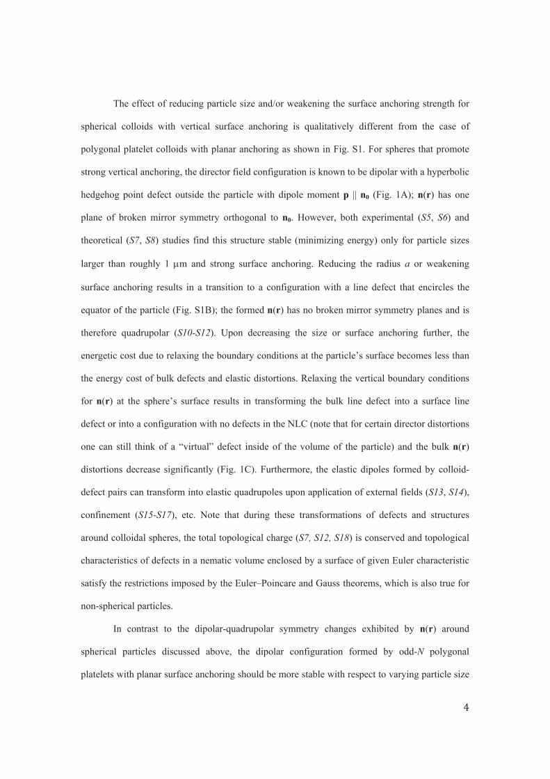
expressed in terms of spatial gradients of n(r):
(S1)
where K11, K22, and K33 are three independent Frank elastic constants corresponding to “splay”,
“bend”, and “twist” deformations respectively (S18) and the integration is carried out over the
volume of the NLC. The three elastic constants of thermotropic small molecule nematics are of
the same order of magnitude [e.g. for 5CB at room temperature K11 6.4 pN, K22 3 pN, and K33
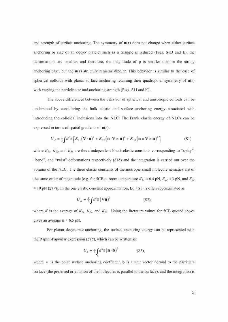
10 pN (S19)]. In the one elastic constant approximation, Eq. (S1) is often approximated as
(S2),
where K is the average of K11, K22, and K33. Using the literature values for 5CB quoted above
gives an average K 6.5 pN.
For planar degenerate anchoring, the surface anchoring energy can be represented with
the Rapini-Papoular expression (S18), which can be written as:
(S3),
where W is the polar surface anchoring coefficent, b is a unit vector normal to the particle’s
surface (the preferred orientation of the molecules is parallel to the surface), and the integration is
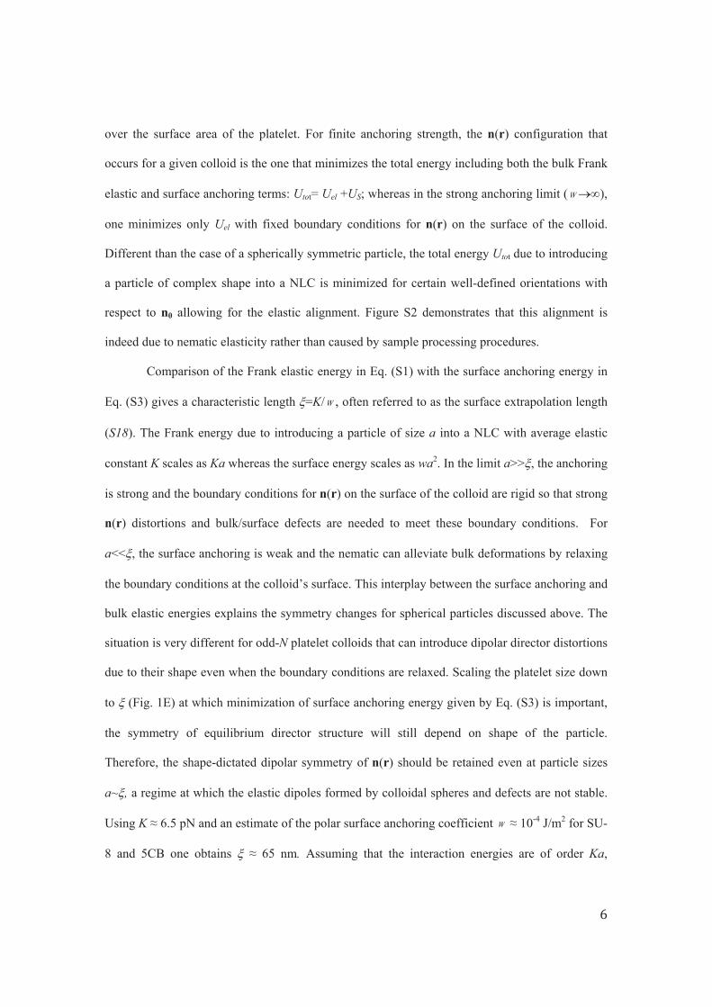
over the surface area of the platelet. For finite anchoring strength, the n(r) configuration that
occurs for a given colloid is the one that minimizes the total energy including both the bulk Frank
elastic and surface anchoring terms: Utot= Uel +US; whereas in the strong anchoring limit ( W ),
one minimizes only Uel with fixed boundary conditions for n(r) on the surface of the colloid.
Different than the case of a spherically symmetric particle, the total energy Utot due to introducing
a particle of complex shape into a NLC is minimized for certain well-defined orientations with
respect to n0 allowing for the elastic alignment. Figure S2 demonstrates that this alignment is
indeed due to nematic elasticity rather than caused by sample processing procedures.
Comparison of the Frank elastic energy in Eq. (S1) with the surface anchoring energy in
Eq. (S3) gives a characteristic length =K/ W , often referred to as the surface extrapolation length
(S18). The Frank energy due to introducing a particle of size a into a NLC with average elastic
constant K scales as Ka whereas the surface energy scales as wa2. In the limit a>> , the anchoring
is strong and the boundary conditions for n(r) on the surface of the colloid are rigid so that strong
n(r) distortions and bulk/surface defects are needed to meet these boundary conditions. For
a<< , the surface anchoring is weak and the nematic can alleviate bulk deformations by relaxing
the boundary conditions at the colloid’s surface. This interplay between the surface anchoring and
bulk elastic energies explains the symmetry changes for spherical particles discussed above. The
situation is very different for odd-N platelet colloids that can introduce dipolar director distortions
due to their shape even when the boundary conditions are relaxed. Scaling the platelet size down
to (Fig. 1E) at which minimization of surface anchoring energy given by Eq. (S3) is important,
the symmetry of equilibrium director structure will still depend on shape of the particle.
Therefore, the shape-dictated dipolar symmetry of n(r) should be retained even at particle sizes
a~ , a regime at which the elastic dipoles formed by colloidal spheres and defects are not stable.
Using K 6.5 pN and an estimate of the polar surface anchoring coefficient W 10-4 J/m2 for SU-
8 and 5CB one obtains 65 nm. Assuming that the interaction energies are of order Ka,
particles with sizes in the range a=50-100 nm (the size range of interest for potential applications
such as self-assembly of optical metamaterials) are expected to bind with energy in the range (50-
100)kBT, suggesting that sub-micron nanoparticles could potentially be assembled via dipole-
dipole interactions.
The symmetry of dipolar and quadrupolar elastic deformations around different
polygonal colloids in the mid-plane of the platelet is similar to the far-field symmetry of n(r)
arising from elastic dipoles and quadrupoles formed by s=±½ disclinations (strength s is defined
as the number of revolutions by 2 that the n(r) makes when one circumnavigates the defect line
once). For example, the dipolar n(r) far from the triangular platelet with p n0 (Fig. S1D and H)
resembles the elastic deformations induced by a s=±½ disclination pair with p also orthogonal to
n0 (Fig. S1F). This disclination dipole is known to be one of two low-energy dipolar defect
geometries (S20) observed in small-molecule thermotropic NLCs (S21) as well as in polymer
liquid crystals (S22). The quadrupolar n(r) induced by a square-shaped colloid (Figs. S1G and
S1H) resembles the far-field director due to a quadropole of four s=±½ disclinations (Fig. S1I).
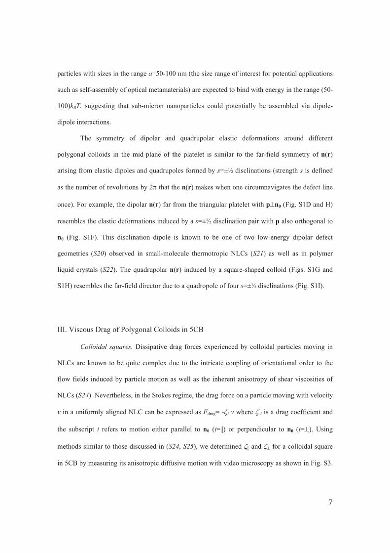
III. Viscous Drag of Polygonal Colloids in 5CB
Colloidal squares. Dissipative drag forces experienced by colloidal particles moving in
NLCs are known to be quite complex due to the intricate coupling of orientational order to the
flow fields induced by particle motion as well as the inherent anisotropy of shear viscosities of
NLCs (S24). Nevertheless, in the Stokes regime, the drag force on a particle moving with velocity
v in a uniformly aligned NLC can be expressed as Fdrag= - i v where i is a drag coefficient and
the subscript i refers to motion either parallel to n0 (i=||) or perpendicular to n0 (i= ). Using
methods similar to those discussed in (S24, S25), we determined || and for a colloidal square
in 5CB by measuring its anisotropic diffusive motion with video microscopy as shown in Fig. S3.
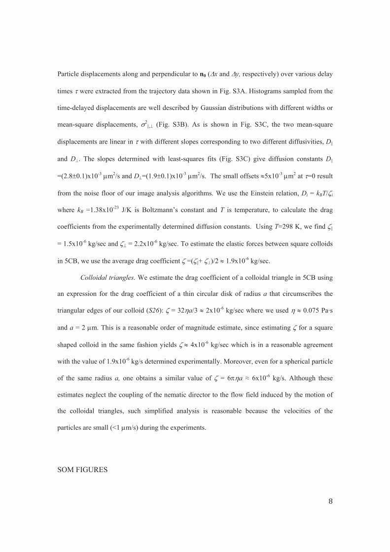
Particle displacements along and perpendicular to n0 ( x and y, respectively) over various delay
times were extracted from the trajectory data shown in Fig. S3A. Histograms sampled from the
time-delayed displacements are well described by Gaussian distributions with different widths or
mean-square displacements, 2||, (Fig. S3B). As is shown in Fig. S3C, the two mean-square
displacements are linear in with different slopes corresponding to two different diffusivities, D||
and D . The slopes determined with least-squares fits (Fig. S3C) give diffusion constants D||
=(2.8 0.1)x10-3 m2/s and D =(1.9 0.1)x10-3 m2/s. The small offsets 5x10⁻³ m2 at =0 result
from the noise floor of our image analysis algorithms. We use the Einstein relation, Di = kBT/ i
where kB =1.38x10⁻²³ J/K is Boltzmann’s constant and T is temperature, to calculate the drag
coefficients from the experimentally determined diffusion constants. Using T=298 K, we find ||
= 1.5x10⁻⁶ kg/sec and = 2.2x10⁻⁶ kg/sec. To estimate the elastic forces between square colloids
in 5CB, we use the average drag coefficient =( ||+ )/2 1.9x10⁻⁶ kg/sec.
Colloidal triangles. We estimate the drag coefficient of a colloidal triangle in 5CB using
an expression for the drag coefficient of a thin circular disk of radius a that circumscribes the
triangular edges of our colloid (S26): = 32 a/3 2x10⁻⁶ kg/sec where we used 0.075 Pa·s
and a = 2 m. This is a reasonable order of magnitude estimate, since estimating for a square
shaped colloid in the same fashion yields 4x10⁻⁶ kg/sec which is in a reasonable agreement
with the value of 1.9x10⁻⁶ kg/s determined experimentally. Moreover, even for a spherical particle
of the same radius a, one obtains a similar value of = 6 a 6x10⁻⁶ kg/s. Although these
estimates neglect the coupling of the nematic director to the flow field induced by the motion of
the colloidal triangles, such simplified analysis is reasonable because the velocities of the
articles are small (<1 m/s) during the experiments. p
SOM FIGURES
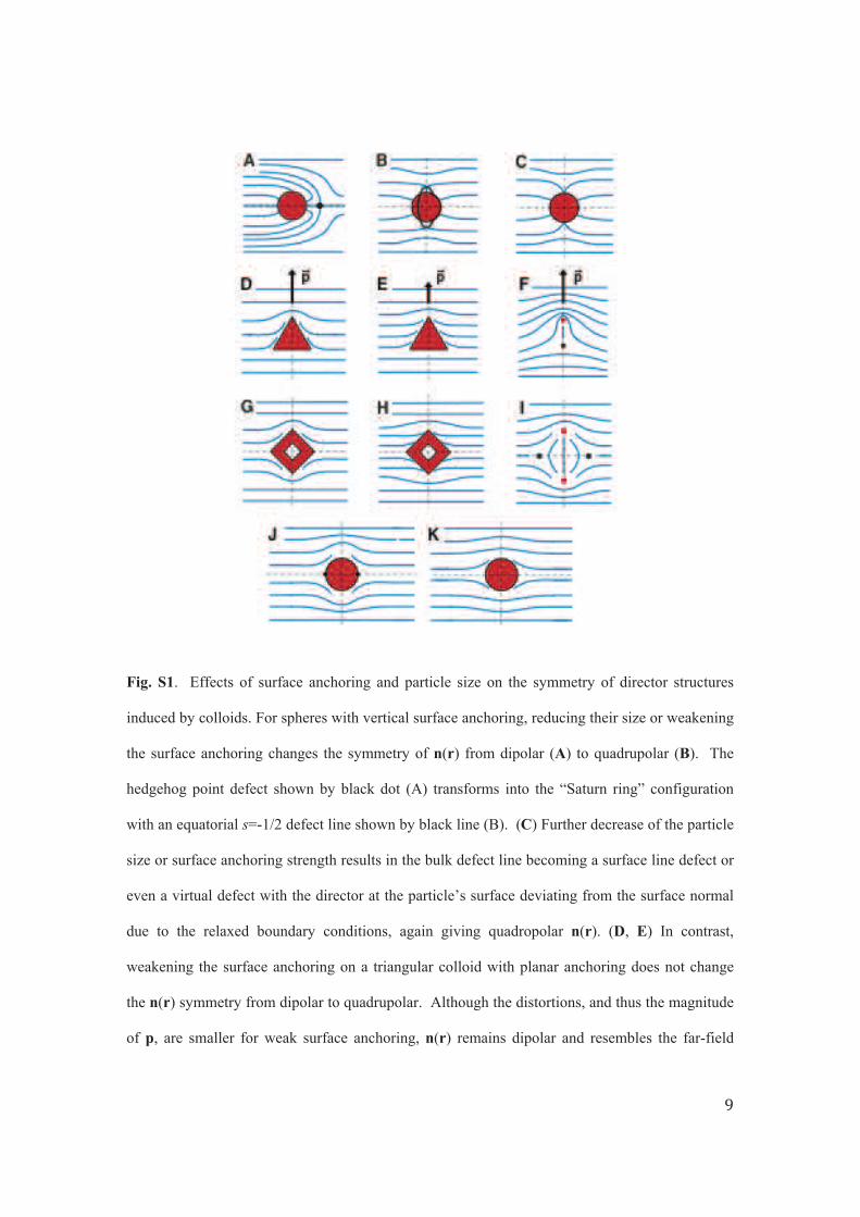
Fig. S1. Effects of surface anchoring and particle size on the symmetry of director structures
induced by colloids. For spheres with vertical surface anchoring, reducing their size or weakening
the surface anchoring changes the symmetry of n(r) from dipolar (A) to quadrupolar (B). The
hedgehog point defect shown by black dot (A) transforms into the “Saturn ring” configuration
with an equatorial s=-1/2 defect line shown by black line (B). (C) Further decrease of the particle
size or surface anchoring strength results in the bulk defect line becoming a surface line defect or
even a virtual defect with the director at the particle’s surface deviating from the surface normal
due to the relaxed boundary conditions, again giving quadropolar n(r). (D, E) In contrast,
weakening the surface anchoring on a triangular colloid with planar anchoring does not change
the n(r) symmetry from dipolar to quadrupolar. Although the distortions, and thus the magnitude
of p, are smaller for weak surface anchoring, n(r) remains dipolar and resembles the far-field
symmetry of distortions around a s=+1/2 (red dot) and s=-1/2 (black dot) dipolar pair of line
defects with p oriented perpendicular to n0 (F). (G, H) Similarly, weakening the surface
anchoring on a square colloid decreases the overall distortions, and thus the magnitude of the
quadrupole moment is smaller; however, the quadrupolar symmetry of n(r) is retained and is
similar to that of the far-field n(r) due to a quadrupole of s=+/-½ line defects (I). (J) For colloidal
spheres with strong planar anchoring, n(r) is quadrupolar with two surface point defects (black
dots) at the poles of the sphere along n0. (K) Decreasing anchoring and spherical particle size
reduces the bulk deformations by relaxing the planar boundary condition for n(r) at the particle’s
surface yet there is no change in the quadrupolar symmetry of n(r).
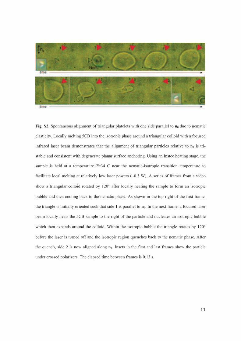
Fig. S2. Spontaneous alignment of triangular platelets with one side parallel to n0 due to nematic
elasticity. Locally melting 5CB into the isotropic phase around a triangular colloid with a focused
infrared laser beam demonstrates that the alignment of triangular particles relative to n0 is tri-
stable and consistent with degenerate planar surface anchoring. Using an Instec heating stage, the
sample is held at a temperature T=34 C near the nematic-isotropic transition temperature to
facilitate local melting at relatively low laser powers (~0.3 W). A series of frames from a video
show a triangular colloid rotated by 120 after locally heating the sample to form an isotropic
bubble and then cooling back to the nematic phase. As shown in the top right of the first frame,
the triangle is initially oriented such that side 1 is parallel to n0. In the next frame, a focused laser
beam locally heats the 5CB sample to the right of the particle and nucleates an isotropic bubble
which then expands around the colloid. Within the isotropic bubble the triangle rotates by 120
before the laser is turned off and the isotropic region quenches back to the nematic phase. After
the quench, side 2 is now aligned along n0. Insets in the first and last frames show the particle
under crossed polarizers. The elapsed time between frames is 0.13 s.
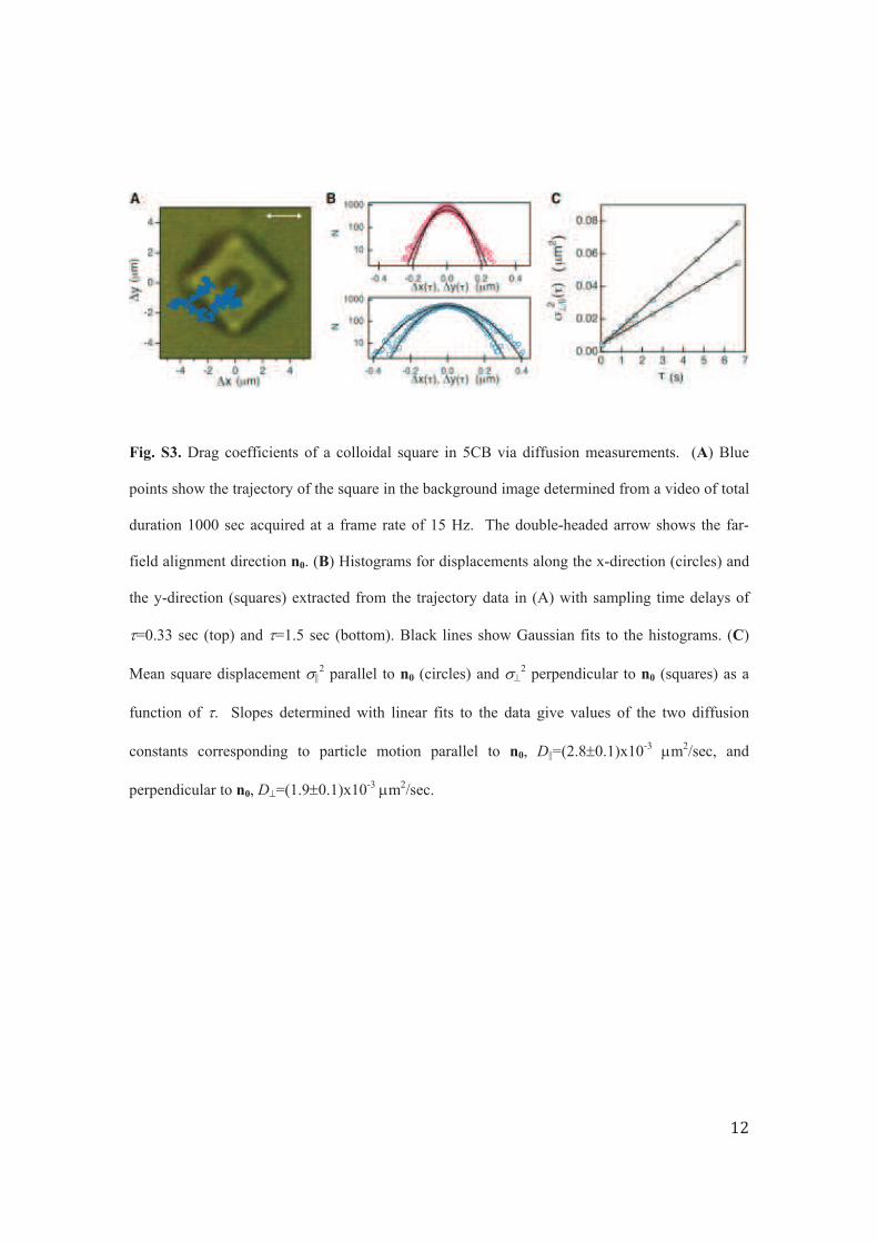
Fig. S3. Drag coefficients of a colloidal square in 5CB via diffusion measurements. (A) Blue
points show the trajectory of the square in the background image determined from a video of total
duration 1000 sec acquired at a frame rate of 15 Hz. The double-headed arrow shows the far-
field alignment direction n0. (B) Histograms for displacements along the x-direction (circles) and
the y-direction (squares) extracted from the trajectory data in (A) with sampling time delays of
=0.33 sec (top) and =1.5 sec (bottom). Black lines show Gaussian fits to the histograms. (C)
Mean square displacement 2 parallel to n0 (circles) and 2 perpendicular to n0 (squares) as a
function of . Slopes determined with linear fits to the data give values of the two diffusion
constants corresponding to particle motion parallel to n0, D||=(2.8 0.1)x10-3 m2/sec, and
perpendicular to n0, D =(1.9 0.1)x10-3 m2/sec.
SOM REFERENCES
(S1) C. J. Hernandez, T. G. Mason, J. Phys. Chem. C 111, 4474 (2007).
(S2) A. Ashkin, Proc. Natl. Acad. Sci. 94, 4853 (1997).
(S3) Z. Cheng, P. M. Chaikin, T. G. Mason, Phys. Rev. Lett. 89, 108303 (2002).
(S4) I. I. Smalyukh, S. V. Shiyanovskii, O. D. Lavrentovich, Chem. Phys. Lett. 336, 88 (2001).
(S5) O. Mondain-Monval, J. C. Dedieu, T. Gulik-Krzywicki, P. Poulin, Eur. Phys. J. B 12, 167
(1999).
(S6) K. Kita, M. Ichikawa, Y. Kimura, Phys. Rev. E 77, 041702 (2008).
(S7) H. Stark, Eur. Phys. J. B 10, 311 (1999).
(S8) D. Andrienko, G. Germano, M. P. Allen, Phys. Rev. E 63, 041701 (2001).
(S9) O. Guzmán, E. B. Kim, S. Grollau, N. L. Abbott, J. J. de Pablo, Phys. Rev. Lett. 91, 235507
(2003).
(S10) P. Poulin, D. A. Weitz, Phys. Rev. E 57, 626 (1998).
(S11) S. Zhang, E. M. Terentjev, A. M. Donald, Macromol. Rapid Commun. 26, 911 (2005).
(S12) M. Kleman, O.D. Lavrentovich, Philosophical Magazine 86, 4117 (2006).
(S13) J. C. Loudet, P. Poulin, Phys. Rev. Lett. 87, 165503 (2001).
(S14) J. Fukuda, H. Yokoyama, Eur. Phys. J. E 21, 341 (2006).
(S15) S. Grollau, N. L. Abbott, J. J. de Pablo, Phys. Rev. E 67, 011702 (2003).
(S16) H. Stark, Phys. Rev. E 66, 032702 (2002).
(S17) J. Fukuda, S. Zumer, Phys. Rev. E 79, 041703 (2009).
(S18) P. G. de Gennes, J. Prost, The Physics of Liquid Crystals (Oxford Univ. Press, Oxford,
1993).
(S19) L. M. Blinov, V. G. Chigrinov, Electrooptic effects in liquid crystal materials (Springer-
Verlag, New York, 1996).
(S20) F. Greco, L. Abbondanza, Mol. Cryst. Liq. Cryst. 188, 155 (1990).
(S21) A. Bogi, P. Martinot-Lagarde, I. Dozov, M. Nobili, Phys. Rev. Lett. 89, 225501 (2002).
(S22) B. A. Wood, E. L. Thomas, Nature 324, 655 (1986).
(S23) H. Stark, D. Ventzki, Phys. Rev. E 64, 031711 (2001).
(S24) J. C. Loudet, P. Hanusse, P. Poulin, Science 306, 1525 (2004).
(S25) M. Skarabot, et al, Phys. Rev. E 73, 021705 (2006).
(S26) W. Zhang, H. A. Stone, J. Fluid Mech. 367, 329 (1998).