Embed Size (px)
Citation preview
Shared Storage Model
A framework for describing storage architectures
SNIA Technical Council [email protected]
Revision status
2001-06-05 last content change 2003-04-13 last graphics change
SNIA TC approved
SNIA Shared Storage Model
SNIA-SSM-text.doc page ii
Revision history
Date By: Comments
February 23, 2001 Wayne Rickard, John Wilkes First Draft
March 8, 2001 Wayne Rickard, Garth Gibson, Dave Anderson, David Black
Second Draft, includes comments from Tech Council review.
March 9, 2001 Wayne Rickard Second Draft, pdf version, minor edits only
April 3, 2001 John Wilkes Third draft; major editorial changes
April 28, 2001 Wayne Rickard Third draft #2; incorporating review comments from SNIA BoD and first public review. This revision prepared for April SNW distribution.
May 14, 2001 John Wilkes Fifth revision. Merged the two divergent branches; replaced the graphics.
June 5, 2001 John Wilkes Revised legal language: final draft of SNIA TC Proposal document.
April 13, 2003 John Wilkes Graphics re-imported from color-corrected slides.
Usage terms The Storage Networking Industry Association (SNIA) hereby grants permission to use this document solely as set forth below, provided that the user complies with and agrees to the terms and conditions set forth below:
1. The user may reproduce, distribute, or display publicly this document (in its entirety). In any reproduction, distribution, or display, the user must not remove any copyright or other proprietary notices or these terms and conditions from this document.
2. The user may also incorporate this document, and/or portions of this document, into other documents or works of authorship, including without limitation articles and books. For any such use, the user must include a reasonably prominent copyright notice acknowledging the SNIA’s copyright in any content in this document and a reasonably prominent acknowledgment crediting the SNIA for granting permission for the use of this document. The user must not assert any claims of ownership or proprietary rights, including without limitation seeking copyright

SNIA Shared Storage Model
SNIA-SSM-text.doc page iii
registration, of or in any content in this document; and the user must not otherwise seek to limit or restrict others’ ability to use this document subject to these terms and conditions.
3. In any use of this document whatsoever, the user may not alter, change, or otherwise modify any of the content in this document. However, in using a diagram from this document, the user may make certain limited changes to the diagram: (a) solely as reasonably necessary to show the placement or interaction of a product (including a planned or hypothetical product) with or relative to the components shown in the diagram; (b) that are text annotations superimposed upon a diagram, solely as reasonably necessary to comment on or explain the diagram, the Shared Storage Model, or other related proposals, research, or analysis; or (c) that are simple graphical annotations (such as arrows, circles, or other geometric figures) to show interaction, relations, groupings, or subsets, solely as reasonably necessary to comment on or explain the diagram, the Shared Storage Model, or other related proposals, research, or analysis.
4. When making any such changes to a diagram permitted under Section 3, above, the user must include a reasonably proximate and prominent notice both of the changes and that any such changes are the sole responsibility of the user (in addition to any notices required by Section 2, above).
5. Notwithstanding anything to the contrary, the user must not make any change to any diagram that: (a) changes the SNIA Shared Storage Model itself (as described in this document); (b) extends the SNIA Shared Storage Model to cover products or applications for which it was not intended (as described in this document); or (c) misrepresents the SNIA Shared Storage Model (as described in this document) in any way, for example, by omitting significant portions of a diagram.
6. Furthermore, the user may make no use of this document that might in any way suggest the SNIA endorses, sponsors, or is affiliated with the user or any products, services, or content provided by the user. The user may not use the names “Storage Networking Industry Association” or “SNIA” to endorse or promote any product, service, or content provided by the user incorporating, based on, or otherwise derived from this document, without prior, express, written permission. However, nothing in these terms and conditions precludes a member of the SNIA from noting it is a member of the SNIA.
THIS DOCUMENT IS PROVIDED “AS IS,” WITHOUT REPRESENTATION OR WARRANTY OF ANY KIND; AND the SNIA EXPRESSLY DISCLAIMS ANY AND ALL WARRANTIES, EXPRESS OR IMPLIED, INCLUDING WITHOUT LIMITATION ANY IMPLIED WARRANTY OF MERCHANTABILITY, FITNESS FOR A PARTICULAR PURPOSE, TITLE, OR NON-INFRINGEMENT, AND/OR ANY IMPLIED WARRANTY ARISING OUT OF A COURSE OF PERFORMANCE, DEALING, OR TRADE USAGE.
UNDER NO CIRCUMSTANCES SHALL THE SNIA, OR ANY OF ITS MEMBERS, OR ANY AUTHOR OF OR CONTRIBUTOR TO THIS DOCUMENT, BE LIABLE TO THE USER FOR DIRECT, INDIRECT, INCIDENTAL, CONSEQUENTIAL, SPECIAL, EXEMPLARY, PUNITIVE, OR OTHER FORM OF DAMAGES (EVEN IF SUCH DAMAGES ARE FORESEEABLE OR THERE HAS BEEN NOTICE OR KNOWLEDGE OF THE POSSIBILITY OF SUCH DAMAGES) ARISING FROM THE USE OF THIS DOCUMENT, REGARDLESS OF WHETHER ANY CLAIM TO SUCH DAMAGES IS BASED IN CONTRACT, WARRANTY, TORT (INCLUDING NEGLIGENCE AND STRICT LIABILITY), PRODUCT LIABILITY, OR OTHER THEORY OF LIABILITY.
YOU HEREBY AGREE TO INDEMNIFY, DEFEND, AND HOLD HARMLESS THE SNIA, OR ANY OF ITS MEMBERS, OR ANY AUTHOR OF OR CONTRIBUTOR TO THIS DOCUMENT, FROM ANY AND ALL THIRD-PARTY CLAIMS OR OTHER LIABILITIES, INCLUDING WITHOUT LIMITATION REASONABLE ATTORNEYS’ FEES, COSTS, AND EXPENSES, ARISING OUT OF OR IN ANY WAY RELATED TO YOUR USE OF THIS DOCUMENT.
Any person’s or company’s retention and/or use of this document manifests his, her, or its assent to the above terms and conditions and agreement not to make any use of this document except as expressly provided above. All rights not explicitly granted are expressly reserved to the SNIA.
Permission to use this document in ways or for purposes not allowed above, or clarifications on permissible changes to diagrams, may be requested by e-mailing [email protected]; please include the identity of the requesting individual and/or company and a brief description of the purpose, nature, and scope of the requested use.
Copyright © 2001,2003 Storage Networking Industry Association.

SNIA Shared Storage Model
SNIA-SSM-text.doc page iv
Table of contents
Executive summary ....................................................................................................................................2 Acknowledgements ....................................................................................................................................3 1 The shared storage vision ...................................................................................................................4
1.1 Why shared storage?..................................................................................................................5 1.2 The potential ................................................................................................................................6
2 Why a model for shared storage?.......................................................................................................7 2.1 Benefits of the model..................................................................................................................7 2.2 A note on the graphical conventions used in the model ........................................................8
3 The classic storage model...................................................................................................................9 4 The SNIA Shared Storage Model.......................................................................................................10
4.1 Storage system components ...................................................................................................10 4.2 The layering scheme of the SNIA Shared Storage Model.....................................................12 4.3 The file/record layer ..................................................................................................................12
4.3.1 Where can it be done? ....................................................................................................13 4.4 The block layer ..........................................................................................................................13
4.4.1 Block aggregation............................................................................................................14 4.4.2 Where can it be done? ....................................................................................................14 4.4.3 How is it done?................................................................................................................15 4.4.4 Sample architectures ......................................................................................................16
4.5 Putting it all together – combining the block & file/record layers .......................................17 4.6 Access paths .............................................................................................................................18
4.6.1 Caching ...........................................................................................................................18 4.6.2 Access control .................................................................................................................19
4.7 The services subsystem...........................................................................................................21 5 Additional topics.................................................................................................................................22
5.1 Clustering...................................................................................................................................22 5.2 Data versus storage..................................................................................................................22 5.3 Sharing of resources and data ................................................................................................23
5.3.1 Resource sharing ............................................................................................................23 5.3.2 Data sharing ....................................................................................................................24
5.4 Modular systems.......................................................................................................................24 5.5 Storage networks ......................................................................................................................26
SNIA Shared Storage Model
SNIA-SSM-text.doc page v
5.5.1 “SAN” vs. “NAS”? ............................................................................................................26 5.5.2 A challenge......................................................................................................................27
6 Some common storage architectures ..............................................................................................28 6.1 Direct-attached block storage..................................................................................................28 6.2 Storage network-attached block storage (aka “SAN”)..........................................................29 6.3 Block storage aggregation in a storage network (“SAN appliance”) ..................................30 6.4 Storage network-attached block storage with metadata server (“asymmetric block service”) ..............................................................................................................................................31 6.5 Multi-site block storage ............................................................................................................32 6.6 File server ..................................................................................................................................33 6.7 File server controller (“NAS head”) ........................................................................................34 6.8 NAS/file server metadata manager (“asymmetric file service”)...........................................35 6.9 Object-based Storage Device (OSD), CMU NASD..................................................................36
7 Summary and conclusions................................................................................................................37 7.1 Status .........................................................................................................................................37
SNIA Shared Storage Model
SNIA-SSM-text.doc page 2
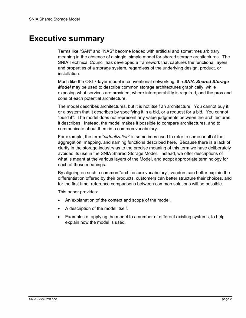
Executive summary Terms like "SAN" and "NAS" become loaded with artificial and sometimes arbitrary meaning in the absence of a single, simple model for shared storage architectures. The SNIA Technical Council has developed a framework that captures the functional layers and properties of a storage system, regardless of the underlying design, product, or installation.
Much like the OSI 7-layer model in conventional networking, the SNIA Shared Storage Model may be used to describe common storage architectures graphically, while exposing what services are provided, where interoperability is required, and the pros and cons of each potential architecture.
The model describes architectures, but it is not itself an architecture. You cannot buy it, or a system that it describes by specifying it in a bid, or a request for a bid. You cannot “build it”. The model does not represent any value judgments between the architectures it describes. Instead, the model makes it possible to compare architectures, and to communicate about them in a common vocabulary.
For example, the term “virtualization” is sometimes used to refer to some or all of the aggregation, mapping, and naming functions described here. Because there is a lack of clarity in the storage industry as to the precise meaning of this term we have deliberately avoided its use in the SNIA Shared Storage Model. Instead, we offer descriptions of what is meant at the various layers of the Model, and adopt appropriate terminology for each of those meanings.
By aligning on such a common “architecture vocabulary”, vendors can better explain the differentiation offered by their products, customers can better structure their choices, and for the first time, reference comparisons between common solutions will be possible.
This paper provides:
• An explanation of the context and scope of the model.
• A description of the model itself.
• Examples of applying the model to a number of different existing systems, to help explain how the model is used.

SNIA Shared Storage Model
SNIA-SSM-text.doc page 3
Acknowledgements The SNIA Shared Storage Model is a cooperative effort of the SNIA Technical Council. It brings together the perspectives of system architects from diverse backgrounds and perspectives in the storage industry. An effort of this scope could only be successful with support from each of the SNIA member organizations that sponsored the individuals, contributing their time and knowledge to the creation and review of this document. The SNIA Board of Directors would like to extend its gratitude to this dedicated group of individuals and their sponsoring companies:
Chief Author, Project Lead John Wilkes, Hewlett Packard
Co-Author David Black, EMC
Co-Author Harald Skardal, Network Appliance
SNIA TC chair, Editor & contributor Wayne Rickard, Gadzoox Networks
Technical Council, contributor Dave Anderson, Seagate Technology
Technical Council, contributor Jim Carlson, IBM
Technical Council, contributor Garth Gibson, CMU
Technical Council, contributor Kevin Phaup, HighGround Systems
Technical Council, contributor David Thiel, Compaq
The Technical Council would also like to recognize the following individuals whose special contributions to the Shared Storage Model helped make the project a success: Paul Massiglia (Veritas), Paul Borrill (Veritas), Andrea Westerinen (Cisco), and Brad Stamas (StorageTek).
SNIA Shared Storage Model
SNIA-SSM-text.doc page 4
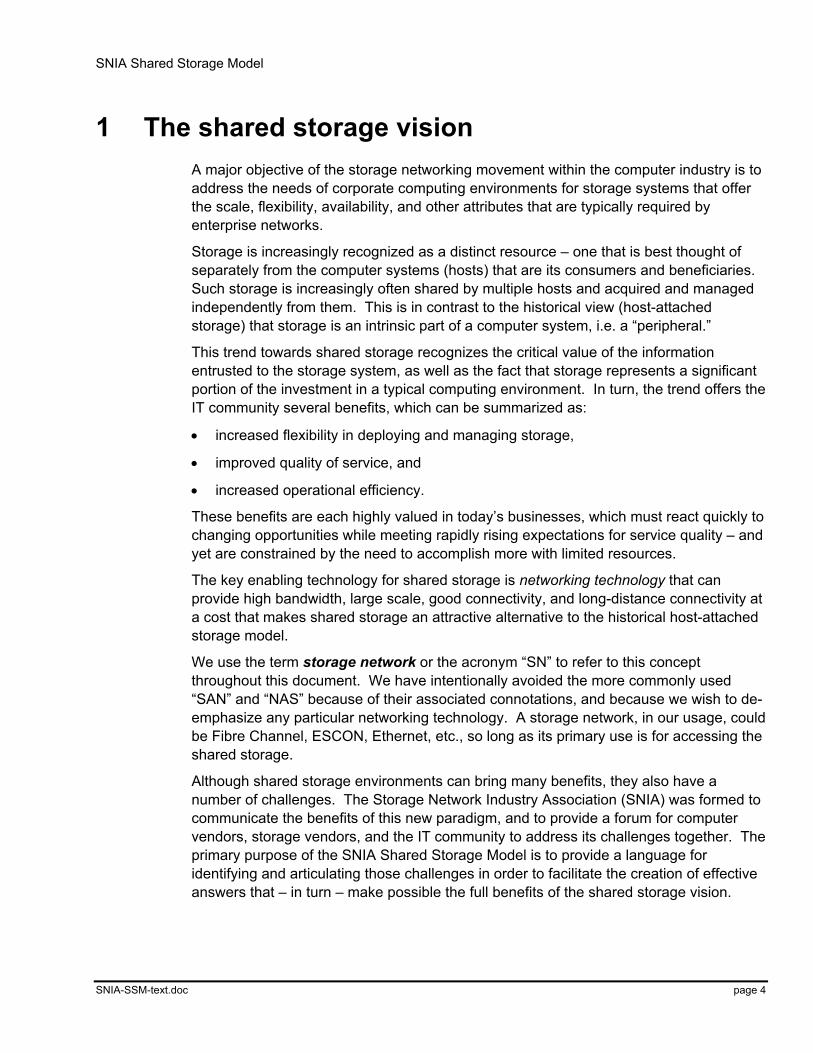
1 The shared storage vision A major objective of the storage networking movement within the computer industry is to address the needs of corporate computing environments for storage systems that offer the scale, flexibility, availability, and other attributes that are typically required by enterprise networks.
Storage is increasingly recognized as a distinct resource – one that is best thought of separately from the computer systems (hosts) that are its consumers and beneficiaries. Such storage is increasingly often shared by multiple hosts and acquired and managed independently from them. This is in contrast to the historical view (host-attached storage) that storage is an intrinsic part of a computer system, i.e. a “peripheral.”
This trend towards shared storage recognizes the critical value of the information entrusted to the storage system, as well as the fact that storage represents a significant portion of the investment in a typical computing environment. In turn, the trend offers the IT community several benefits, which can be summarized as:
• increased flexibility in deploying and managing storage,
• improved quality of service, and
• increased operational efficiency.
These benefits are each highly valued in today’s businesses, which must react quickly to changing opportunities while meeting rapidly rising expectations for service quality – and yet are constrained by the need to accomplish more with limited resources.
The key enabling technology for shared storage is networking technology that can provide high bandwidth, large scale, good connectivity, and long-distance connectivity at a cost that makes shared storage an attractive alternative to the historical host-attached storage model.
We use the term storage network or the acronym “SN” to refer to this concept throughout this document. We have intentionally avoided the more commonly used “SAN” and “NAS” because of their associated connotations, and because we wish to de-emphasize any particular networking technology. A storage network, in our usage, could be Fibre Channel, ESCON, Ethernet, etc., so long as its primary use is for accessing the shared storage.
Although shared storage environments can bring many benefits, they also have a number of challenges. The Storage Network Industry Association (SNIA) was formed to communicate the benefits of this new paradigm, and to provide a forum for computer vendors, storage vendors, and the IT community to address its challenges together. The primary purpose of the SNIA Shared Storage Model is to provide a language for identifying and articulating those challenges in order to facilitate the creation of effective answers that – in turn – make possible the full benefits of the shared storage vision.
SNIA Shared Storage Model
SNIA-SSM-text.doc page 5
1.1 Why shared storage?
Through much of the history of computing, storage has been seen as an intrinsic part of computer systems. While storage once was regarded as a “peripheral,” more recently, it has come to be thought of as a storage subsystem, but still uniquely associated with a computer. The principal exceptions to this have been mainframe computer complexes and computer clusters where a modest number of cooperating computer systems share a common set of storage devices.
As business has become more dependent upon computing, it has also become more dependent upon data, the life-blood of computing. While a failed processor can usually be readily replaced and operations continued almost immediately after the replacement, a failed storage resource requires replacement followed by typically time-consuming restoration of data, all too often with some loss of recent changes to that data that requires recovery action, before operations can continue. As a result, storage and the disciplines of caring for data and the storage on which it resides have gown in visibility and importance.
In addition, the fraction of the purchase price of a computer system that is represented by the storage component has grown over time to the point that now the storage component of a computer system is often in the vicinity of half of the total price.
Beyond the purchase price of storage, the total cost of owning storage has become a significant part of the cost of maintaining the computing environment. In other words, the acquisition cost is a small portion of the total cost of ownership of storage over its lifetime.
Computing environments have grown as business has become increasingly reliant on computing. As this has happened, computer systems have grown in size and in number. Because the traditional computing model associates storage uniquely with a computer system, a computing environment with many computer systems has many storage and storage management environments to maintain and operate – one per computer system.
In responding to these trends, the IT community has come to view storage as a resource that should be purchased and managed independently of the computer systems that it serves. The IT community has also increasingly come to view storage as a resource that should be shared among computer systems. These changes allow more focused attention on storage, which is expected to lead to reduced costs and higher levels of service, and more flexibility through the sharing of the storage resource. This, in turn, allows IT professionals to provide improved quality and response time as business needs change.
As the storage system for a computing environment becomes a shared, independent resource, additional requirements emerge:
• Reliability – as required of any large, shared, critical resource
• Scalability – to match the size, performance, and physical and geographic placement of computing environments
SNIA Shared Storage Model
SNIA-SSM-text.doc page 6
• Manageability – to provide high levels of service, and achieve the expected reduction in operational expenses
• Standards-based interoperation – to avoid excessive vendor dependence in a large, critical component of data centers
Another key trend is the evolution in communications technology that has made available high performance communication between many nodes over distances ranging from a few inches to fully global systems at reasonable cost. (Despite this, high performance over large distances is still relatively expensive compared to local connectivity, and it is subject to speed-of-light related delays that can be significant in comparison to storage device access times.)
When all of this is considered, a structure emerges that achieves the goals of reliability, scalability, and manageability. That structure is a storage system comprising many computer systems that are the consumers of the storage system, many storage devices, and extensive management capabilities; all interconnected richly and with the necessary high performance. This is the shared storage environment.
1.2 The potential
Shared storage is a powerful concept, bringing together into single storage systems essentially unbounded collections of interconnected and geographically unconstrained storage resources and management capabilities.
This redefines storage, where traditional storage systems are very limited (both in scope and extent) and where management capabilities are typically distinct from storage systems.
The power of the shared storage environment lies in a richly interconnected set of resources and defining the storage environment as a storage system in its own right. The former opens many avenues for exploiting connectivity. The latter enables the storage system to be the focus of invention, deployment, and operation as an entity independent of the hosts that it serves. Many aspects of ongoing activity under the “storage networking” umbrella support these claims; it is likely that more are to come given the high level of energy being applied to this field.
Some examples of potential benefits are:
• Reduced Total Cost of Ownership (TCO) of storage solutions through intelligent Storage Resource Management. For example, if three servers share a pool of storage, they need not each have spare storage to accommodate growth but can pull from a common pool. They also may share a backup resource that each can use.
• Better performance or efficiency through use of network enabled storage management approaches, i.e. "server independent" storage management, consolidated storage management, data movers, 3rd party copy, etc.
SNIA Shared Storage Model
SNIA-SSM-text.doc page 7
2 Why a model for shared storage? This document presents the SNIA Shared Storage Model, which describes a set of practical, possible storage network architectures.
Such an architecture describes a particular functional partitioning of services across the physical and logical resources in a shared storage environment. In use, an architecture is used to develop a storage system design, which includes things like the quantity and size of the resources, and possibly choices of suppliers, versions, etc. A completed design contains enough information to allow construction of a real system that conforms to it.
The SNIA Shared Storage Model is deliberately simple on the surface: the goal is to make it easy to use, yet rich enough to cover a wide range of storage networks that are being – or could be – deployed. To make this easier, the model is primarily described in a graphical form, supported by a concise terminology that supports the key concepts.
A major intent of the model is to highlight the fundamental structures of a storage system that have the largest effect on the system's value proposition. These include, but are not limited to:
• The functions or services that a storage network architecture can support.
• The division of functional responsibility among the components of the system
• Relationships between control and data flows.
• Boundary conditions where interoperability is likely to be an issue. This includes both places where interactions take place between architecture modules (and hence interoperability is required), and what kinds of interoperability must occur there.
• The implications of interface abstraction on technology evolution and marketplace competition.
Of course, the model doesn’t explicitly cover all possible architectures. Instead, the intent is that the user of the model can use it to develop and describe his or her own particular mix of architectural elements and choices. Nonetheless, our experience with it to date has been that it is capable of covering a wide variety of different architectures and designs. It is likely, therefore, that the model does cover a new situation – although perhaps not in the most immediately obvious way.
2.1 Benefits of the model
The benefits from a model of this form are that it can:
• Provide a common vocabulary that people comparing and designing architectures can use to communicate with one another, and make their design efforts and documentation more precise. (The analogy here is with the “definitions of terms” that
SNIA Shared Storage Model
SNIA-SSM-text.doc page 8
are an important deliverable from the IETF and standards bodies.) This will also make it easier for vendors to explain their offerings to customers.
• Provide a common way of recording network storage architectures, so that these architectures can be compared and contrasted with one another, making it easier for customers to compare different architectures and proposals.
Overall, the hope is that this common “vocabulary” will help to align the storage industry for the mutual benefit of all of its participants and customers.
Note that although the model describes architectures, it is not itself an architecture. You cannot buy it, or a system that it describes by specifying it in a bid, or a request for a bid. You cannot “build it”. The model does not represent any value judgments between the architectures it describes. Instead, the model makes it possible to compare architectures, and to communicate about them in a common vocabulary.
2.2 A note on the graphical conventions used in the model
Throughout the model, we have tried to be consistent about the following graphical conventions:
• 3D objects represent physical entities (hosts, switches, etc)
• 2D objects with drop shadows represent functional entities
• Orange/ochre represents storage devices
• Dark blue represents host computer systems
• Pale blue represents storage networks
• Green represents file-level entities
• Yellow is used for caches
• Thick lines represent the major data transfer paths; thinner lines with arrowheads represents paths over which metadata flows
• Diagonal stripes indicate metadata managers
• The vertical placement is also important: particularly in the block subsystem layer.
SNIA Shared Storage Model
SNIA-SSM-text.doc page 9
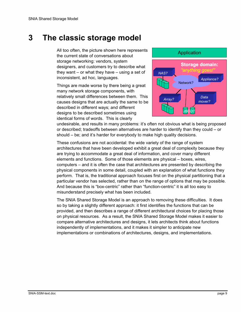
3 The classic storage model All too often, the picture shown here represents the current state of conversations about storage networking: vendors, system designers, and customers try to describe what they want – or what they have – using a set of inconsistent, ad hoc, languages.
Things are made worse by there being a great many network storage components, with relatively small differences between them. This causes designs that are actually the same to be described in different ways; and different designs to be described sometimes using identical forms of words. This is clearly undesirable, and results in many problems: it’s often not obvious what is being proposed or described; tradeoffs between alternatives are harder to identify than they could – or should – be; and it’s harder for everybody to make high quality decisions.
These confusions are not accidental: the wide variety of the range of system architectures that have been developed exhibit a great deal of complexity because they are trying to accommodate a great deal of information, and cover many different elements and functions. Some of those elements are physical – boxes, wires, computers – and it is often the case that architectures are presented by describing the physical components in some detail, coupled with an explanation of what functions they perform. That is, the traditional approach focuses first on the physical partitioning that a particular vendor has selected, rather than on the range of options that may be possible. And because this is “box-centric” rather than “function-centric” it is all too easy to misunderstand precisely what has been included.
The SNIA Shared Storage Model is an approach to removing these difficulties. It does so by taking a slightly different approach: it first identifies the functions that can be provided, and then describes a range of different architectural choices for placing those on physical resources. As a result, the SNIA Shared Storage Model makes it easier to compare alternative architectures and designs, it lets architects think about functions independently of implementations, and it makes it simpler to anticipate new implementations or combinations of architectures, designs, and implementations.
Application
Storage domain:“anything goes!”
Network?Appliance?
Data mover?Array?
NAS?
JBOD?
Application
Storage domain:“anything goes!”
Network?Appliance?
Data mover?Array?
NAS?
JBOD?

SNIA Shared Storage Model
SNIA-SSM-text.doc page 10
4 The SNIA Shared Storage Model
File/record layerFile/record layer
Block layerBlock layer
Storage devices (disks, …)Storage devices (disks, …)
Database(dbms)
Database(dbms)
File system(FS)
File system(FS)
Sto
rag
e d
om
ain
Ser
vice
sS
ervi
ces
Network
Host
DeviceBlock aggregation
Network
Host
DeviceBlock aggregation
Application
This is the highest-level picture of the SNIA Shared Storage Model. It has three main components within its scope:
1. The file/record layer, which includes databases and file systems.
2. The block layer, which includes both low-level storage devices and block-based aggregation.
3. A services subsystem, which provides functions such as the management of the other components.
Note that applications lie outside the scope of the model – they are viewed as “clients” of the storage domain, in the broadest sense.
4.1 Storage system components
The SNIA Shared Storage Model supports the following kinds of components:
• Interconnection network – the network infrastructure that connects the elements of the shared storage environment. This network may be a network that is primarily used for storage access, or one that is also shared with other uses. The important requirement is that it provides an appropriately rich, high-performance, scalable connectivity upon which a shared storage environment can be based.
The physical-layer network technologies that are used (or have been used) for this function include Fibre Channel, Fast- and Gigabit-Ethernet, Myrinet, the VAX CI network, and ServerNet. Network protocols that are used at higher layers of the protocol stack also cover a wide range, including SCSI FCP, TCP/IP, VI, CIFS, and NFS.
SNIA Shared Storage Model
SNIA-SSM-text.doc page 11
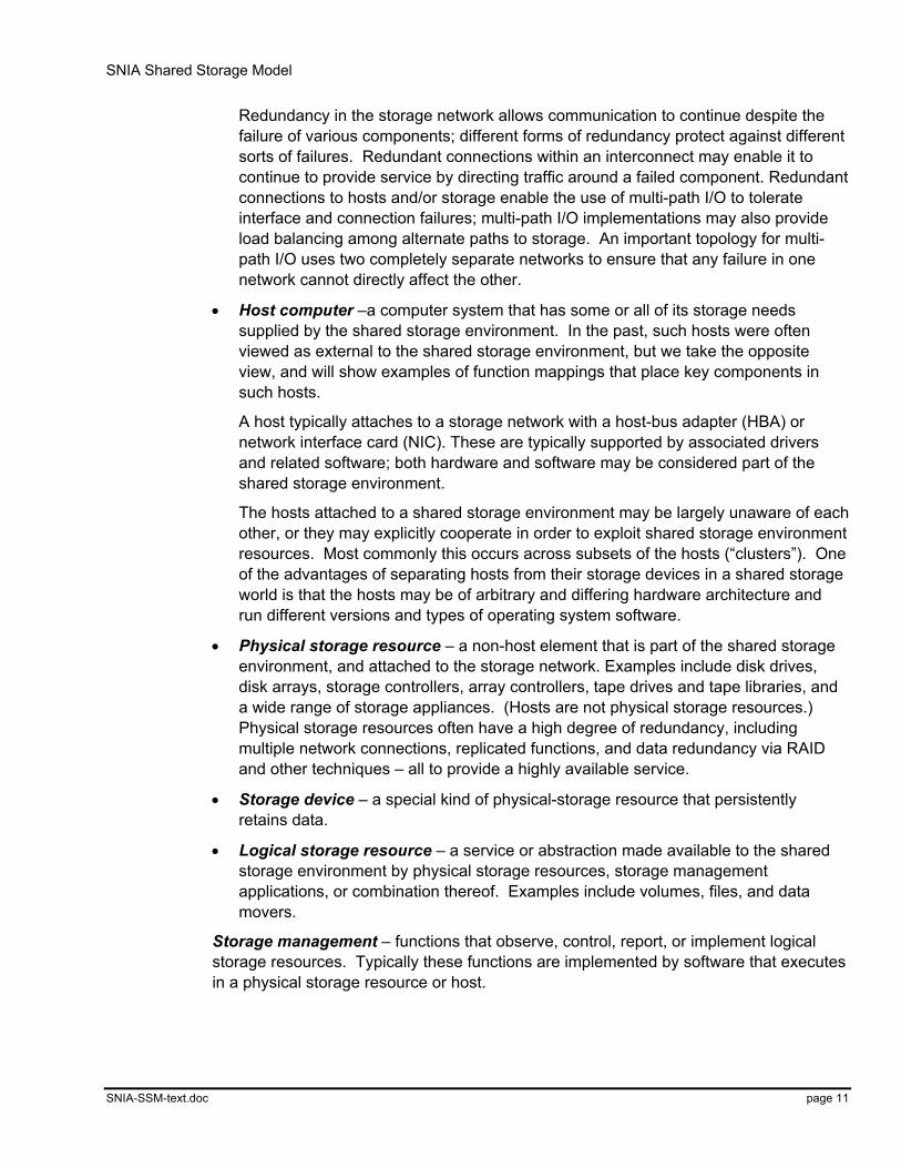
Redundancy in the storage network allows communication to continue despite the failure of various components; different forms of redundancy protect against different sorts of failures. Redundant connections within an interconnect may enable it to continue to provide service by directing traffic around a failed component. Redundant connections to hosts and/or storage enable the use of multi-path I/O to tolerate interface and connection failures; multi-path I/O implementations may also provide load balancing among alternate paths to storage. An important topology for multi-path I/O uses two completely separate networks to ensure that any failure in one network cannot directly affect the other.
• Host computer –a computer system that has some or all of its storage needs supplied by the shared storage environment. In the past, such hosts were often viewed as external to the shared storage environment, but we take the opposite view, and will show examples of function mappings that place key components in such hosts.
A host typically attaches to a storage network with a host-bus adapter (HBA) or network interface card (NIC). These are typically supported by associated drivers and related software; both hardware and software may be considered part of the shared storage environment.
The hosts attached to a shared storage environment may be largely unaware of each other, or they may explicitly cooperate in order to exploit shared storage environment resources. Most commonly this occurs across subsets of the hosts (“clusters”). One of the advantages of separating hosts from their storage devices in a shared storage world is that the hosts may be of arbitrary and differing hardware architecture and run different versions and types of operating system software.
• Physical storage resource – a non-host element that is part of the shared storage environment, and attached to the storage network. Examples include disk drives, disk arrays, storage controllers, array controllers, tape drives and tape libraries, and a wide range of storage appliances. (Hosts are not physical storage resources.) Physical storage resources often have a high degree of redundancy, including multiple network connections, replicated functions, and data redundancy via RAID and other techniques – all to provide a highly available service.
• Storage device – a special kind of physical-storage resource that persistently retains data.
• Logical storage resource – a service or abstraction made available to the shared storage environment by physical storage resources, storage management applications, or combination thereof. Examples include volumes, files, and data movers.
Storage management – functions that observe, control, report, or implement logical storage resources. Typically these functions are implemented by software that executes in a physical storage resource or host.
SNIA Shared Storage Model
SNIA-SSM-text.doc page 12
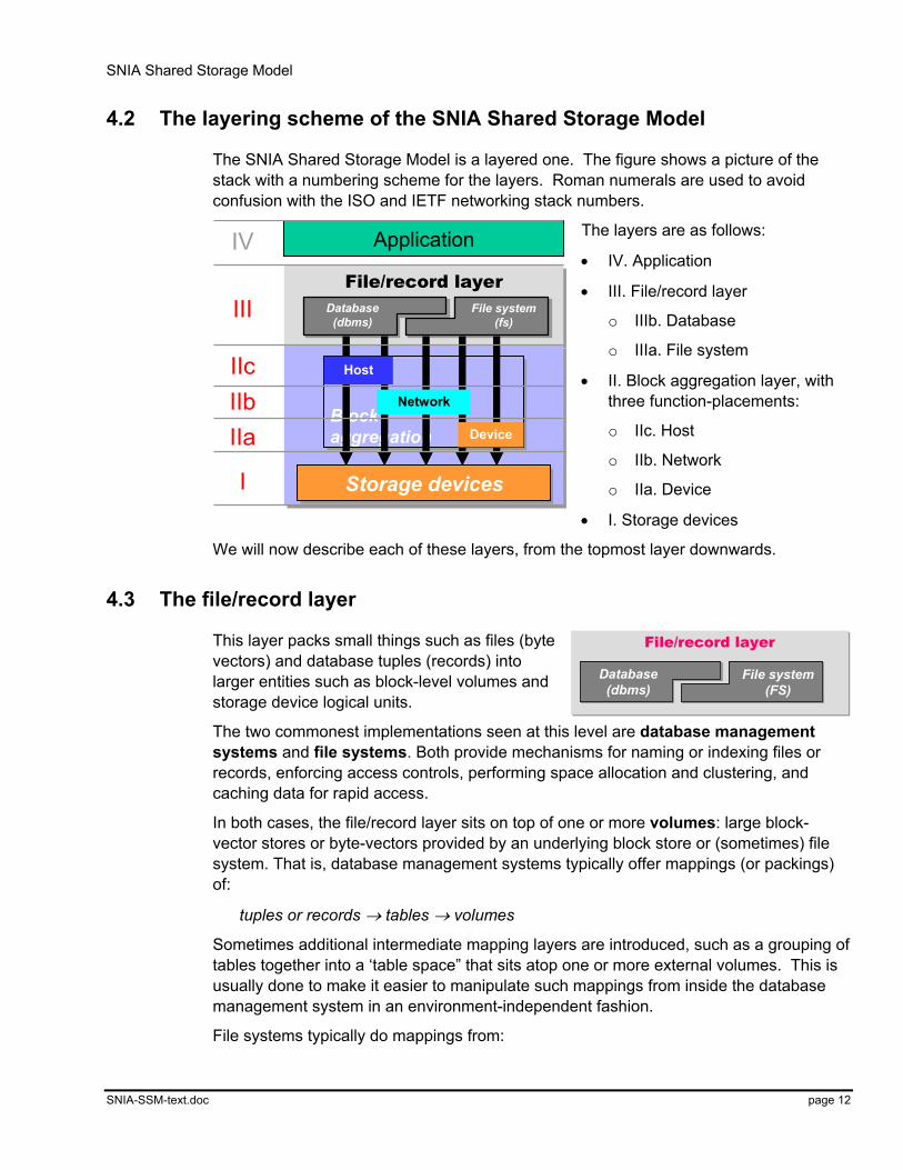
4.2 The layering scheme of the SNIA Shared Storage Model
The SNIA Shared Storage Model is a layered one. The figure shows a picture of the stack with a numbering scheme for the layers. Roman numerals are used to avoid confusion with the ISO and IETF networking stack numbers.
The layers are as follows:
• IV. Application
• III. File/record layer
o IIIb. Database
o IIIa. File system
• II. Block aggregation layer, with three function-placements:
o IIc. Host
o IIb. Network
o IIa. Device
• I. Storage devices
We will now describe each of these layers, from the topmost layer downwards.
4.3 The file/record layer
This layer packs small things such as files (byte vectors) and database tuples (records) into larger entities such as block-level volumes and storage device logical units.
The two commonest implementations seen at this level are database management systems and file systems. Both provide mechanisms for naming or indexing files or records, enforcing access controls, performing space allocation and clustering, and caching data for rapid access.
In both cases, the file/record layer sits on top of one or more volumes: large block-vector stores or byte-vectors provided by an underlying block store or (sometimes) file system. That is, database management systems typically offer mappings (or packings) of:
tuples or records → tables → volumes
Sometimes additional intermediate mapping layers are introduced, such as a grouping of tables together into a ‘table space” that sits atop one or more external volumes. This is usually done to make it easier to manipulate such mappings from inside the database management system in an environment-independent fashion.
File systems typically do mappings from:
File/record layerFile/record layerDatabase
(dbms)File system
(fs)
Storage devicesStorage devices
Block aggregationBlock aggregation
Application
Network
Host
Device
IV
III
IIcIIbIIa
I
File/record layerFile/record layer
Database(dbms)
Database(dbms)
File system(FS)
File system(FS)

SNIA Shared Storage Model
SNIA-SSM-text.doc page 13
bytes → files → volumes
Because a byte vector can be used to emulate a block vector, the volumes that a database is mapped to can sometimes be files. This is most often done for small database systems where the performance penalties of the two levels of mapping it entails are outweighed by the simpler management that results from exploiting the naming and access control mechanisms offered by the file system.
Secondary functionality provided by this layer may include content indexing, aggressive prefetching and write-behind techniques to improve performance, hierarchy management, and providing coherency across multiple copies in distributed systems.
In the future, we expect to see new implementations at this layer, such as file systems explicitly designed for replaying isochronous streams against multimedia objects (e.g., videos). Indeed, an http web cache might be considered a new kind of distributed file system.
4.3.1 Where can it be done?
The functions provided by the file/record layer can be implemented in several different places:
• Solely in the host: these are the traditional host-based file systems and databases (the left hand column in the figure shown here). In such systems, the implementation of the file system or database resides completely in the host, and the interface to the storage device is at the block-vector level.
• In both client and server: these are the standard “network” file systems such as NFS, CIFS, etc. (The right-hand column of the figure.) Such implementations split their functions between the client (host) and the server system. (Note that this split happens inside the file system layer in the SNIA Shared Storage Model.) The client side always resides in a host computer. The server side, however, can reside in a:
o file server (sometimes: database server) – typically a host computer with local attached block storage devices that may be dedicated to this function.
o NAS head – a dedicated-function computer acting as a file server and relying on external block storage devices connected through a storage network.
o storage device – such as a disk array or “smart disk”.
4.4 The block layer
The block layer provides low-level storage to higher layers, typically with an access interface that supports one or more linear vectors of fixed-size blocks. In SCSI, these logical address spaces are called logical units (LUs); a single SCSI storage device may support several such logical units.
device
NAS
Hos
t with
NFS
/CIF
Scl
ient
Hos
t with
loca
lFS
/dbm
s
SNIA Shared Storage Model
SNIA-SSM-text.doc page 14
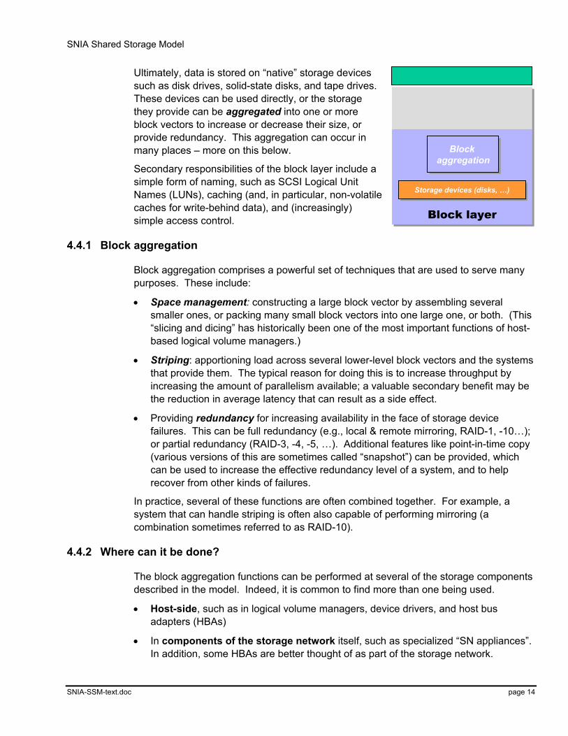
Ultimately, data is stored on “native” storage devices such as disk drives, solid-state disks, and tape drives. These devices can be used directly, or the storage they provide can be aggregated into one or more block vectors to increase or decrease their size, or provide redundancy. This aggregation can occur in many places – more on this below.
Secondary responsibilities of the block layer include a simple form of naming, such as SCSI Logical Unit Names (LUNs), caching (and, in particular, non-volatile caches for write-behind data), and (increasingly) simple access control.
4.4.1 Block aggregation
Block aggregation comprises a powerful set of techniques that are used to serve many purposes. These include:
• Space management: constructing a large block vector by assembling several smaller ones, or packing many small block vectors into one large one, or both. (This “slicing and dicing” has historically been one of the most important functions of host-based logical volume managers.)
• Striping: apportioning load across several lower-level block vectors and the systems that provide them. The typical reason for doing this is to increase throughput by increasing the amount of parallelism available; a valuable secondary benefit may be the reduction in average latency that can result as a side effect.
• Providing redundancy for increasing availability in the face of storage device failures. This can be full redundancy (e.g., local & remote mirroring, RAID-1, -10…); or partial redundancy (RAID-3, -4, -5, …). Additional features like point-in-time copy (various versions of this are sometimes called “snapshot”) can be provided, which can be used to increase the effective redundancy level of a system, and to help recover from other kinds of failures.
In practice, several of these functions are often combined together. For example, a system that can handle striping is often also capable of performing mirroring (a combination sometimes referred to as RAID-10).
4.4.2 Where can it be done?
The block aggregation functions can be performed at several of the storage components described in the model. Indeed, it is common to find more than one being used.
• Host-side, such as in logical volume managers, device drivers, and host bus adapters (HBAs)
• In components of the storage network itself, such as specialized “SN appliances”. In addition, some HBAs are better thought of as part of the storage network.
Block layerBlock layer
Storage devices (disks, …)Storage devices (disks, …)
Block aggregation
Block aggregation
Block layerBlock layer
Storage devices (disks, …)Storage devices (disks, …)
Block aggregation
Block aggregation
SNIA Shared Storage Model
SNIA-SSM-text.doc page 15
• And, very commonly, in the storage devices themselves: disk array controllers (e.g., RAID) are classic examples of this. Modern disk drive controllers provide some level of this functionality too, such as a logical-to-physical block mapping for supporting sparing.
4.4.3 How is it done?
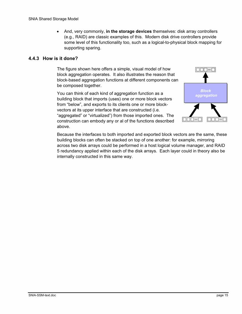
The figure shown here offers a simple, visual model of how block aggregation operates. It also illustrates the reason that block-based aggregation functions at different components can be composed together.
You can think of each kind of aggregation function as a building block that imports (uses) one or more block vectors from “below”, and exports to its clients one or more block-vectors at its upper interface that are constructed (i.e. “aggregated” or “virtualized”) from those imported ones. The construction can embody any or al of the functions described above.
Because the interfaces to both imported and exported block vectors are the same, these building blocks can often be stacked on top of one another: for example, mirroring across two disk arrays could be performed in a host logical volume manager, and RAID 5 redundancy applied within each of the disk arrays. Each layer could in theory also be internally constructed in this same way.
……
……
Block aggregation
Block aggregation
SNIA Shared Storage Model
SNIA-SSM-text.doc page 16
4.4.4 Sample architectures
Device block-aggregation
Network block-aggregation
Host block-aggregation
Device block-aggregation
Network block-aggregation
Host block-aggregation
Host
. with
LVM
and
softw
are R
AID
1. Direct-attach
Host
. with
LVM
and
softw
are R
AID
Host
. with
LVM
and
softw
are R
AID
1. Direct-attach
SNHo
st. w
ith L
VM
Disk array
2. SN-attach
SNHo
st. w
ith L
VM
Disk array
SNSNHo
st. w
ith L
VM
Disk array
2. SN-attach3. SN aggregation
Aggregationappliance
Host
,no
LVM
3. SN aggregation
Aggregationappliance
Host
,no
LVM
3. SN aggregation
Aggregationappliance
Host
,no
LVM
File
/reco
rdla
yer
Blo
ckla
yer
Application
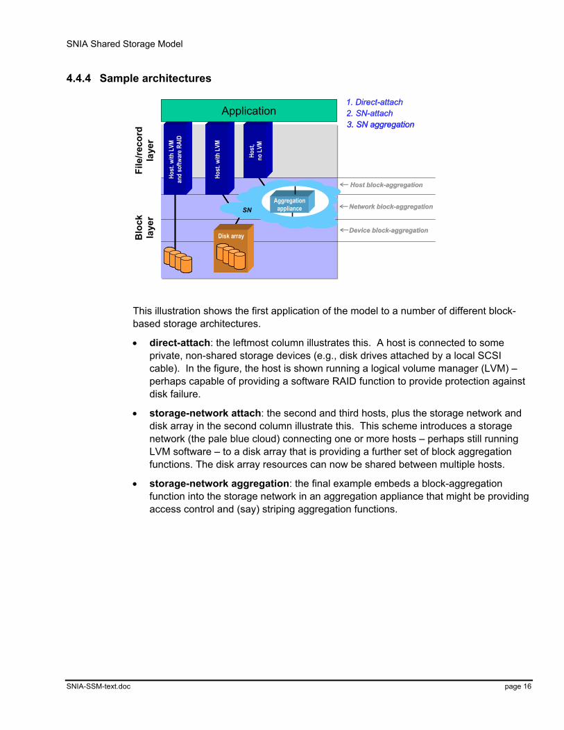
This illustration shows the first application of the model to a number of different block-based storage architectures.
• direct-attach: the leftmost column illustrates this. A host is connected to some private, non-shared storage devices (e.g., disk drives attached by a local SCSI cable). In the figure, the host is shown running a logical volume manager (LVM) – perhaps capable of providing a software RAID function to provide protection against disk failure.
• storage-network attach: the second and third hosts, plus the storage network and disk array in the second column illustrate this. This scheme introduces a storage network (the pale blue cloud) connecting one or more hosts – perhaps still running LVM software – to a disk array that is providing a further set of block aggregation functions. The disk array resources can now be shared between multiple hosts.
• storage-network aggregation: the final example embeds a block-aggregation function into the storage network in an aggregation appliance that might be providing access control and (say) striping aggregation functions.
SNIA Shared Storage Model
SNIA-SSM-text.doc page 17
4.5 Putting it all together – combining the block & file/record layers
Device block-aggregation
Network block-aggregation
Host block-aggregation
Device block-aggregation
Network block-aggregation
Host block-aggregation
Host
. with
LVM
and
softw
are R
AID
Host
. with
LVM
and
softw
are R
AID
1. Direct-attach
File
/reco
rdla
yer
Blo
ckla
yer
NASserver
4. NAS server
NASserver
4. NAS serverHost3. NAS head
NAS head
Host
LAN
Host
. with
LVM
Disk array
SNHo
st. w
ith L
VM
Disk arrayDisk array
SNSN
2. SN-attachApplication
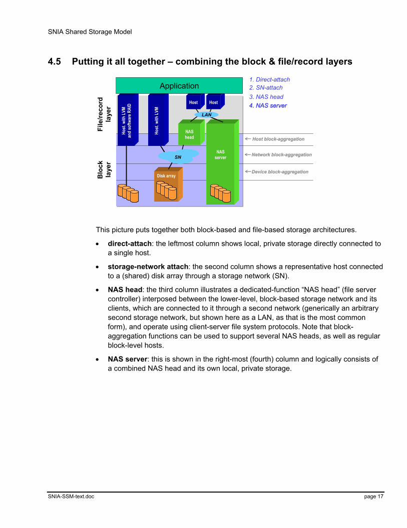
This picture puts together both block-based and file-based storage architectures.
• direct-attach: the leftmost column shows local, private storage directly connected to a single host.
• storage-network attach: the second column shows a representative host connected to a (shared) disk array through a storage network (SN).
• NAS head: the third column illustrates a dedicated-function “NAS head” (file server controller) interposed between the lower-level, block-based storage network and its clients, which are connected to it through a second network (generically an arbitrary second storage network, but shown here as a LAN, as that is the most common form), and operate using client-server file system protocols. Note that block-aggregation functions can be used to support several NAS heads, as well as regular block-level hosts.
• NAS server: this is shown in the right-most (fourth) column and logically consists of a combined NAS head and its own local, private storage.
SNIA Shared Storage Model
SNIA-SSM-text.doc page 18
4.6 Access paths
File/record layerFile/record layer
Database(dbms)
Database(dbms)
File system(FS)
File system(FS)
Block layerBlock layer
Storage devices (disks, …)Storage devices (disks, …)
Block aggregationBlock aggregation
Note: all 8 possible paths can be used!
Note: all 8 possible paths can be used!
Note: all 8 possible paths can be used!
Note: all 8 possible paths can be used!
Application
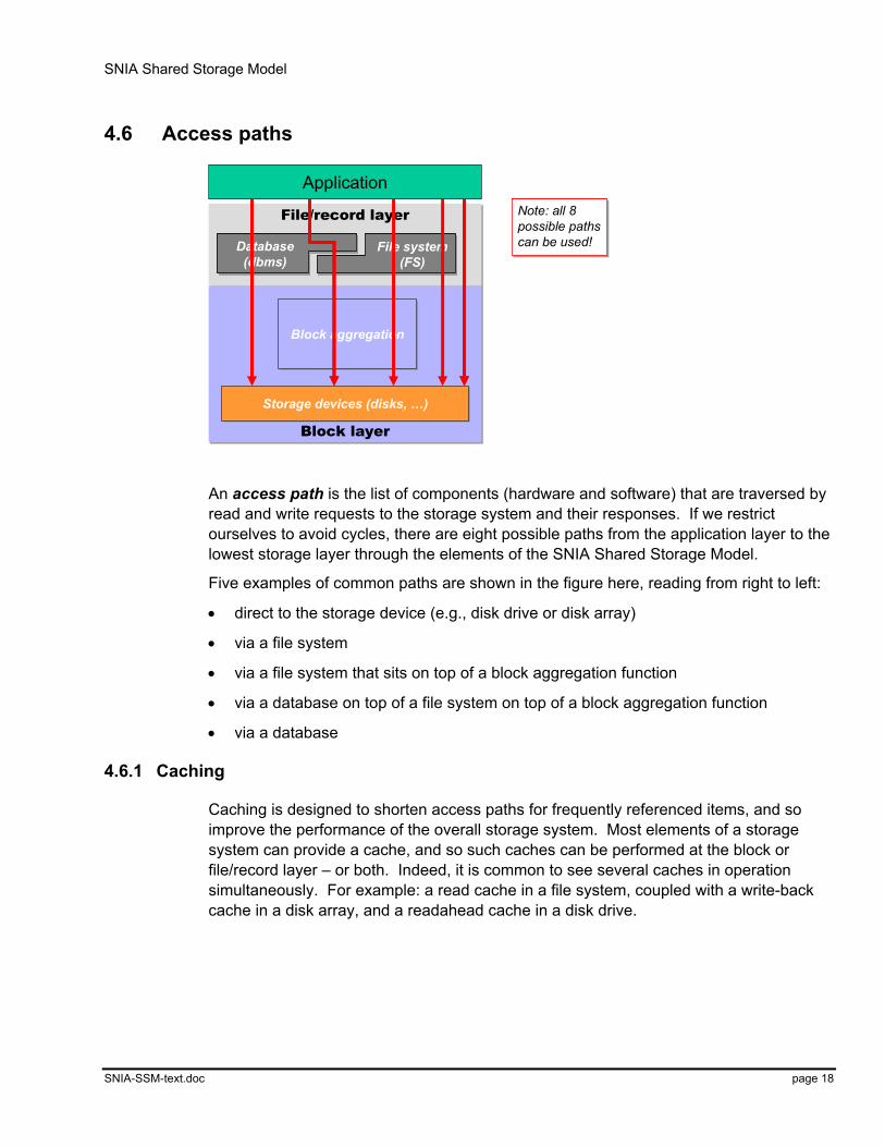
An access path is the list of components (hardware and software) that are traversed by read and write requests to the storage system and their responses. If we restrict ourselves to avoid cycles, there are eight possible paths from the application layer to the lowest storage layer through the elements of the SNIA Shared Storage Model.
Five examples of common paths are shown in the figure here, reading from right to left:
• direct to the storage device (e.g., disk drive or disk array)
• via a file system
• via a file system that sits on top of a block aggregation function
• via a database on top of a file system on top of a block aggregation function
• via a database
4.6.1 Caching
Caching is designed to shorten access paths for frequently referenced items, and so improve the performance of the overall storage system. Most elements of a storage system can provide a cache, and so such caches can be performed at the block or file/record layer – or both. Indeed, it is common to see several caches in operation simultaneously. For example: a read cache in a file system, coupled with a write-back cache in a disk array, and a readahead cache in a disk drive.
SNIA Shared Storage Model
SNIA-SSM-text.doc page 19
Device block-aggregation
Network block-aggregation
Host block-aggregation
Device block-aggregation
Network block-aggregation
Host block-aggregation
Host
. with
LVM
and
softw
are R
AID
File
/reco
rdla
yer
Blo
ckla
yer
Host
NAS head
Host
Host
. with
LVM
Disk arrayDisk array
SNSN
NAS head
LAN
Ideally, caching only affects performance. But: coherency implications do affect management (protocols, interfaces)
Ideally, caching only affects performance. But: coherency implications do affect management (protocols, interfaces)
Application
Cache
Cache
Cache
Cache
Cacheappliance
Cache
Cache
Cache
Cache
Cache
Cacheappliance
Cache
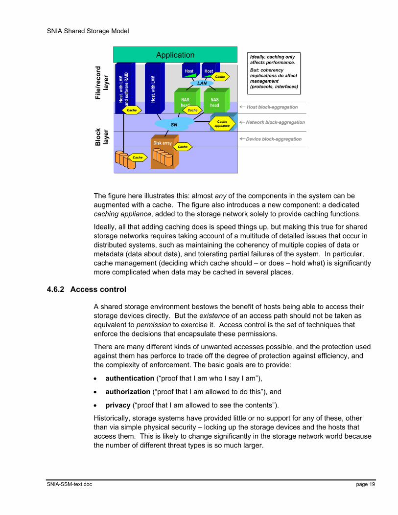
The figure here illustrates this: almost any of the components in the system can be augmented with a cache. The figure also introduces a new component: a dedicated caching appliance, added to the storage network solely to provide caching functions.
Ideally, all that adding caching does is speed things up, but making this true for shared storage networks requires taking account of a multitude of detailed issues that occur in distributed systems, such as maintaining the coherency of multiple copies of data or metadata (data about data), and tolerating partial failures of the system. In particular, cache management (deciding which cache should – or does – hold what) is significantly more complicated when data may be cached in several places.
4.6.2 Access control
A shared storage environment bestows the benefit of hosts being able to access their storage devices directly. But the existence of an access path should not be taken as equivalent to permission to exercise it. Access control is the set of techniques that enforce the decisions that encapsulate these permissions.
There are many different kinds of unwanted accesses possible, and the protection used against them has perforce to trade off the degree of protection against efficiency, and the complexity of enforcement. The basic goals are to provide:
• authentication (“proof that I am who I say I am”),
• authorization (“proof that I am allowed to do this”), and
• privacy (“proof that I am allowed to see the contents”).
Historically, storage systems have provided little or no support for any of these, other than via simple physical security – locking up the storage devices and the hosts that access them. This is likely to change significantly in the storage network world because the number of different threat types is so much larger.
SNIA Shared Storage Model
SNIA-SSM-text.doc page 20
Ultimately, all approaches to access control rely on some form of secure channel being established between the provider of data (or operations on that data) and its destination. The least secure, but also easiest to implement, solution imposes simple, coarse-grained accessor checks (of the form “is this host permitted to send requests to this storage device?”); at the other extreme lies cryptographic protection mechanisms that are resistant to a wide variety of impersonation, monitoring, and replay attacks, and capable even of securely storing data on storage devices that cannot be trusted not to divulge (or lose) their contents.
Preventing unwanted accesses can be performed in several places:
• At the host: this offers convenience of implementation, easy scalability, low execution cost, and potentially fine-grained control, but it must be pervasively deployed, and the enforcement mechanism should be resistant to tampering. With support from their host operating systems, file systems and databases commonly enforce access controls on data, and similar kinds of solutions are appearing at the block vector layer.
Networking stacks in the host can also use encryption to provide secure channels across various forms of network (e.g., IPsec). The performance of software versions of these schemes means today that they are best suited to use on relatively low–speed network links (such as a wide area network), but this is likely to change with the deployment of hardware accelerators.
• In the storage network: today, this is largely restricted to relatively low-level approaches that offer the illusion of private, dedicated sub-networks that permit a set of host and storage device ports access only to one another, hiding any other ports. (These are usually called zones in Fibre Channel, or VLANs in the Ethernet world.) Because they operate on whole ports, such solutions are quite coarse-grained.
But, by analogy with the migration of functions such as load balancing into traditional IP networking components, it is reasonable to expect finer-grain controls appearing in storage network switches, such as the ability to enforce such virtual networks on per-logical-unit (LU) boundaries.
• At the storage devices: ultimately, storage devices will probably have to accept as much responsibility for enforcing access controls as the hosts do: they are, after all, the primary shared resource that storage networking is trying to make available. This has long been true of servers at the file/record layer such as file servers and NAS heads; and now solutions are appearing that perform a simple form of “LU masking” at the block layer, where only certain host (or host ports) are allowed access to a particular LU.
As storage networks span ever-greater numbers of devices, and encompass greater heterogeneity of host types, host software, and distances, the importance of this issue will greatly increase.
SNIA Shared Storage Model
SNIA-SSM-text.doc page 21
4.7 The services subsystem
Sto
rag
e d
om
ain
File/record layerFile/record layer
Block layerBlock layer
Application
Storage devices (disks, …)Storage devices (disks, …)
Block aggregationBlock aggregation
Database(dbms)
Database(dbms)
File system(fs)
File system(fs)
Ser
vice
sS
ervi
ces
Dis
cove
ry, m
onito
ring
Dis
cove
ry, m
onito
ring
Res
ourc
e m
gmt,
conf
igur
atio
nR
esou
rce
mgm
t, co
nfig
urat
ion
Sec
urity
, bill
ing
Sec
urity
, billi
ngR
edun
danc
y m
gmt (
back
up, …
)R
edun
danc
y m
gmt (
back
up, …
)H
igh
avai
labi
lity
(fail-
over
, …)
Hig
h av
aila
bilit
y (fa
il-ov
er, …
)C
apac
ity p
lann
ing
Cap
acity
pla
nnin
g
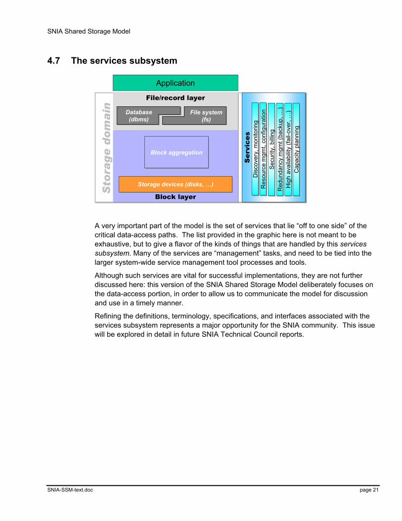
A very important part of the model is the set of services that lie “off to one side” of the critical data-access paths. The list provided in the graphic here is not meant to be exhaustive, but to give a flavor of the kinds of things that are handled by this services subsystem. Many of the services are “management” tasks, and need to be tied into the larger system-wide service management tool processes and tools.
Although such services are vital for successful implementations, they are not further discussed here: this version of the SNIA Shared Storage Model deliberately focuses on the data-access portion, in order to allow us to communicate the model for discussion and use in a timely manner.
Refining the definitions, terminology, specifications, and interfaces associated with the services subsystem represents a major opportunity for the SNIA community. This issue will be explored in detail in future SNIA Technical Council reports.
SNIA Shared Storage Model
SNIA-SSM-text.doc page 22
5 Additional topics This section pulls together some additional areas that the model touches on that don’t readily or conveniently fit into the layered structure identified above.
5.1 Clustering
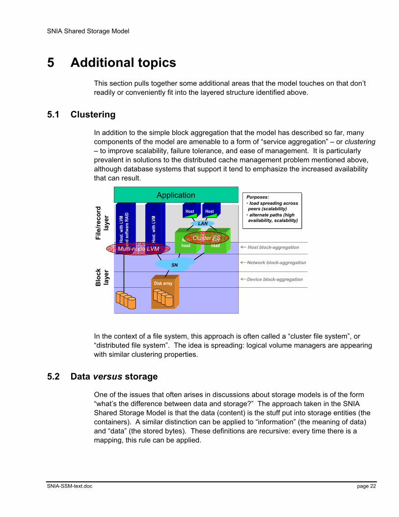
In addition to the simple block aggregation that the model has described so far, many components of the model are amenable to a form of “service aggregation” – or clustering – to improve scalability, failure tolerance, and ease of management. It is particularly prevalent in solutions to the distributed cache management problem mentioned above, although database systems that support it tend to emphasize the increased availability that can result.
Device block-aggregation
Network block-aggregation
Host block-aggregation
Device block-aggregation
Network block-aggregation
Host block-aggregation
Host
. with
LVM
and
softw
are R
AID
File
/reco
rdla
yer
Blo
ckla
yer
Host
NAS head
Host
Host
. with
LVM
Disk array
SN
NAS head
LAN
Cluster FS
Multi-node LVM
Purposes:• load spreading across peers (scalability)
• alternate paths (high availability, scalability)
Purposes:• load spreading across peers (scalability)
• alternate paths (high availability, scalability)
Application
In the context of a file system, this approach is often called a “cluster file system”, or “distributed file system”. The idea is spreading: logical volume managers are appearing with similar clustering properties.
5.2 Data versus storage
One of the issues that often arises in discussions about storage models is of the form “what’s the difference between data and storage?” The approach taken in the SNIA Shared Storage Model is that the data (content) is the stuff put into storage entities (the containers). A similar distinction can be applied to “information” (the meaning of data) and “data” (the stored bytes). These definitions are recursive: every time there is a mapping, this rule can be applied.

SNIA Shared Storage Model
SNIA-SSM-text.doc page 23
For example:
User: data (“learning my preferences”)
Application: container(“user keystroke history”)
Application: data (“user keystroke history file”)
file system: container (“byte vector”)
file system: data (“a named file”)
volume system: container (“blocks in volume”)
volume system: data (“replicated, striped layout”)
disk array: container (“blocks in LU”)
5.3 Sharing of resources and data
With host-attached storage, storage resources are accessible, managed, and organized solely by the host to which they are directly connected. No other hosts can access, manage, or organize these storage resources except through the host to which they directly connected.
This difficulty can be alleviated in a shared storage environment: storage resources can be directly accessible by many hosts, and can be considered a common pool of storage resources. While this capability offers many benefits, e.g. in the area of flexibility, it also creates the requirement that access be controlled (see section 4.6.2).
To further explore this topic, a distinction must be made between resource sharing and data sharing.
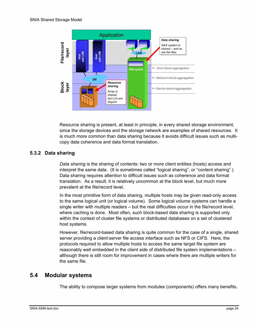
5.3.1 Resource sharing
Resource sharing is the shared use of just the storage system resources – those portions of the storage system that provide its containers (see section 5.2) – not the containers themselves, nor their contents.
Shared resources commonly include the network and physical storage resources such as storage controllers, disk arrays, tape libraries, disk drives, tape drives, etc. attached to it. A simple example is an array controller that provides a logical unit (LU) to one host and a different LU to a second host. The network, the array controller – and possibly even the array’s disk drives – are shared resources, but the LUs are not shared in any way.
SNIA Shared Storage Model
SNIA-SSM-text.doc page 24
Device block-aggregation
Network block-aggregation
Host block-aggregation
Device block-aggregation
Network block-aggregation
Host block-aggregation
Host
with
LVM
File
/reco
rdla
yer
Blo
ckla
yer
Host
with
LVM
SN
NAS system
HostHost
LAN
Application
Resource sharing
Array is shared,but LUs are disjoint
Resource sharing
Array is shared,but LUs are disjoint
Data sharing
NAS system is shared – and so are the files
Data sharing
NAS system is shared – and so are the files
Resource sharing is present, at least in principle, in every shared storage environment, since the storage devices and the storage network are examples of shared resources. It is much more common than data sharing because it avoids difficult issues such as multi-copy data coherence and data format translation.
5.3.2 Data sharing
Data sharing is the sharing of contents: two or more client entities (hosts) access and interpret the same data. (It is sometimes called “logical sharing”, or “content sharing”.) Data sharing requires attention to difficult issues such as coherence and data format translation. As a result, it is relatively uncommon at the block level, but much more prevalent at the file/record level.
In the most primitive form of data sharing, multiple hosts may be given read-only access to the same logical unit (or logical volume). Some logical volume systems can handle a single writer with multiple readers – but the real difficulties occur in the file/record level, where caching is done. Most often, such block-based data sharing is supported only within the context of cluster file systems or distributed databases on a set of clustered host systems.
However, file/record-based data sharing is quite common for the case of a single, shared server providing a client:server file access interface such as NFS or CIFS. Here, the protocols required to allow multiple hosts to access the same target file system are reasonably well embedded in the client side of distributed file system implementations – although there is still room for improvement in cases where there are multiple writers for the same file.
5.4 Modular systems
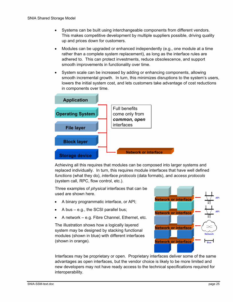
The ability to compose larger systems from modules (components) offers many benefits.
SNIA Shared Storage Model
SNIA-SSM-text.doc page 25
• Systems can be built using interchangeable components from different vendors. This makes competitive development by multiple suppliers possible, driving quality up and prices down for customers.
• Modules can be upgraded or enhanced independently (e.g., one module at a time rather than a complete system replacement), as long as the interface rules are adhered to. This can protect investments, reduce obsolescence, and support smooth improvements in functionality over time.
• System scale can be increased by adding or enhancing components, allowing smooth incremental growth. In turn, this minimizes disruptions to the system’s users, lowers the initial system cost, and lets customers take advantage of cost reductions in components over time.
Storage device
Block layer
File layer
Operating System
Application
Network or interface
Full benefits come only fromcommon, openinterfaces
Full benefits come only fromcommon, openinterfaces
Achieving all this requires that modules can be composed into larger systems and replaced individually. In turn, this requires module interfaces that have well defined functions (what they do), interface protocols (data formats), and access protocols (system call, RPC, flow control, etc.).
Three examples of physical interfaces that can be used are shown here.
• A binary programmatic interface, or API;
• A bus – e.g., the SCSI parallel bus;
• A network – e.g. Fibre Channel, Ethernet, etc.
The illustration shows how a logically layered system may be designed by stacking functional modules (shown in blue) with different interfaces (shown in orange).
Interfaces may be proprietary or open. Proprietary interfaces deliver some of the same advantages as open interfaces, but the vendor choice is likely to be more limited and new developers may not have ready access to the technical specifications required for interoperability.
Network or interface
Network or interface
Network or interface
Network or interface
Network
Bus
API
API
SNIA Shared Storage Model
SNIA-SSM-text.doc page 26
It is the position of the SNIA that the full benefits of modular systems are only likely to be realized through the development of common, open interfaces that see wide adoption. As a result, SNIA promotes the development of open, industry-standard interfaces that have well-understood, well-documented specifications. It is also important that the specifications be published (which includes open discussion of changes under formal revision control), and are supported by multiple products. Industry standards processes are an important way of achieving these goals, which is why SNIA is active in supporting them.
5.5 Storage networks
The SNIA Shared Storage Model does not explicitly include details of the storage network, such as whether or not to use network switches or a particular kind of interconnection technology. This is intentional: the model is network- and transport-neutral: although it relies only on the existence of storage networks and module interfaces to achieve the functional decompositions that it describes, it is not particular about the precise details of those networks or interfaces.
For example, much has been made of the merits of switched networks, and their importance to the shared storage environment. But in the context of the SNIA Shared Storage Model, it is worth emphasizing that this arises primarily because of their good networking properties, rather than anything specific to storage systems: smooth scalability, fault-tolerance through supporting redundant paths, support for heterogeneity in end-node types, access at a distance, and reasonable cost for high aggregate performance.
To date, most shared-storage networks for the block level have been built on Fibre Channel, and most shared file/record-level networks on Ethernet. In the future, the range is likely to become broader (e.g., encompassing Sonet, and InfiniBand), and it seems likely that IP-based storage transport protocols will come into being for block-level storage traffic.
5.5.1 “SAN” vs. “NAS”?
While the SNIA Shared Storage Model uses functional decomposition to show what could be built, many product vendors have taken vertical and horizontal slices of the model, explicitly specified the protocols and interconnect, and positioned the resulting products in broadly generalized categories. SAN (Storage Area Network) and NAS (Network Attached Storage) are two such categories.
We have deliberately avoided using the terms “SAN” and “NAS” until now, because the potential preconceptions carried with these terms detract from the implementation neutral nature of the Shared Storage Model. This section encourages the user to look beyond the labels attached to implementations, consider the usage models, and apply informed best judgment.
SNIA Shared Storage Model
SNIA-SSM-text.doc page 27
For example, it is frequently the case that network implementation choices are presented as either/or decisions: Fibre Channel or Ethernet or InfiniBand at the hardware level? FCP or TCP/IP transport protocols? Block-level or file/record-level access protocols?
In reality, of course, a combination of the appropriate choices from this space is the best response, rather than slavish adherence to one choice for all purposes. Each has their place; each has their advantages and disadvantages.
For the purposes of the SNIA Shared Storage Model, we define a storage network (SN) as any (mostly) dedicated network, that is installed (mostly) for storage traffic, whatever the hardware, API, or protocol. For example, far from being direct competitors, the “SAN” and “NAS” models actually address different functional layers of the Shared Storage Model, and thus may be implemented in a complementary manner.
As technologies change, generalized terms become more difficult to rationalize. Is iSCSI (running the block system over TCP/IP over an Ethernet network) still a SAN? Is running a file system such as DAFS (Direct Attach File System) over VI over Fibre Channel a NAS?
These distinctions become less relevant in the presence of the transport neutrality of the SNIA Shared Storage Model. In turn, this allows decisions to focus on the consequences of each design choice, rather than adherence to simplistic “slogans”. Thus, we encourage the end users of storage networking technology to return to the Shared Storage Model with an focus on the problem to be solved, rather than the terminology used to describe the solution. In this way, unnecessary semantic battles can be avoided.
5.5.2 A challenge
Many of the standards or solutions needed to make the promise of shared storage a reality do not yet exist, or exist only in primitive or proprietary forms. Simply put, most operating systems and volume managers still expect a wire, not a complex, intelligent interconnect, between them and their storage devices.
Some of the issues that need to be solved by standardization in the storage networking industry include initialization, discovery, end-to-end binding, address mapping, address distribution and management, name services, and event management. Many of these problems will need to be solved multiple times, because although the Shared Storage Model is transport neutral, the simple act of selecting a particular transport means buying into a particular set of support mechanisms (or services) that may be incomplete.
Future work by the SNIA Technical Council and Technical Working groups will focus on the “services subsystem” part of the Shared Storage Model, where many of these issues reside.

SNIA Shared Storage Model
SNIA-SSM-text.doc page 28
6 Some common storage architectures This section explores some of the more common (and emerging) storage architectures, and maps them to the SNIA Shared Storage Model. You should be able to recognize many familiar products in these mappings, and for the first time, be able to compare a wide range of architectures against a common model.
6.1 Direct-attached block storage
Device block-aggregation
Network block-aggregation
Host block-aggregation
Device block-aggregation
Network block-aggregation
Host block-aggregation
Disk arrayDisk array
Host
,no
LVM
File
/reco
rdla
yer
Blo
ckla
yer
Host
. with
LVM
and
softw
are R
AID
Host
wi
th L
VM
Application • Direct-attach
• Multi-attach boxE.g., SCSI
• Direct-attach
• Multi-attach boxE.g., SCSI
Direct-attached block storage is the most common, most mature, least shared, high-performance storage design. It is characterized by:
• having only one (active) host on each storage interconnect wire,
• the absence of switches or hubs, and by
• the use of a block interface protocol for operations over the interconnect.
Aggregation may occur at the device (e.g., array controller) or host (e.g., logical volume manager, software or hardware RAID implementation).
SNIA Shared Storage Model
SNIA-SSM-text.doc page 29
6.2 Storage network-attached block storage (aka “SAN”)
Device block-aggregation
Network block-aggregation
Host block-aggregation
Device block-aggregation
Network block-aggregation
Host block-aggregation
Disk array
Host
,no
LVM
File
/reco
rdla
yer
Blo
ckla
yer
SN
“SN” = any networkused for storage access.E.g., Fibre Channel,Ethernet, …
“SN” = any networkused for storage access.E.g., Fibre Channel,Ethernet, …
Host
with
LVM
Application
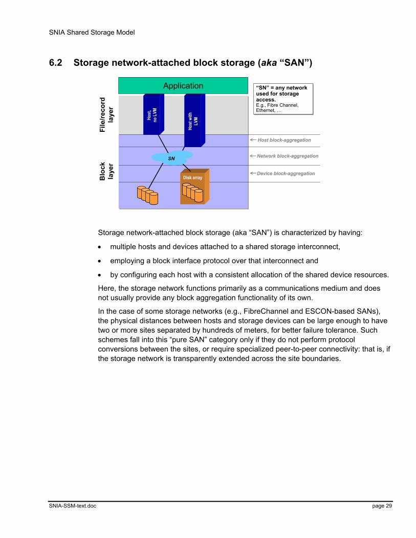
Storage network-attached block storage (aka “SAN”) is characterized by having:
• multiple hosts and devices attached to a shared storage interconnect,
• employing a block interface protocol over that interconnect and
• by configuring each host with a consistent allocation of the shared device resources.
Here, the storage network functions primarily as a communications medium and does not usually provide any block aggregation functionality of its own.
In the case of some storage networks (e.g., FibreChannel and ESCON-based SANs), the physical distances between hosts and storage devices can be large enough to have two or more sites separated by hundreds of meters, for better failure tolerance. Such schemes fall into this “pure SAN” category only if they do not perform protocol conversions between the sites, or require specialized peer-to-peer connectivity: that is, if the storage network is transparently extended across the site boundaries.
SNIA Shared Storage Model
SNIA-SSM-text.doc page 30
6.3 Block storage aggregation in a storage network (“SAN appliance”)
Device block-aggregation
Network block-aggregation
Host block-aggregation
Device block-aggregation
Network block-aggregation
Host block-aggregation
Disk array
SNSN
File
/reco
rdla
yer
Blo
ckla
yer
Aggregationappliance
Host
with
LVM Ho
st,
no L
VM
Application aka “SNvirtualization”Functions: LVM, caching
aka “SNvirtualization”Functions: LVM, caching
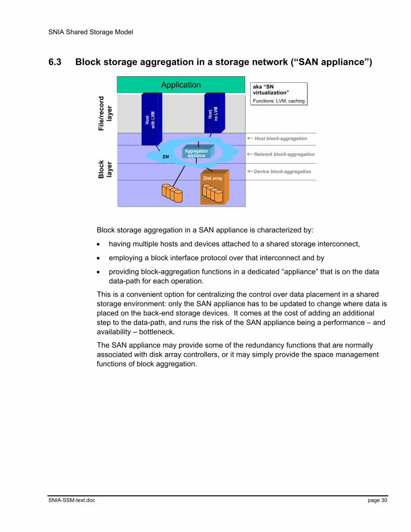
Block storage aggregation in a SAN appliance is characterized by:
• having multiple hosts and devices attached to a shared storage interconnect,
• employing a block interface protocol over that interconnect and by
• providing block-aggregation functions in a dedicated “appliance” that is on the data data-path for each operation.
This is a convenient option for centralizing the control over data placement in a shared storage environment: only the SAN appliance has to be updated to change where data is placed on the back-end storage devices. It comes at the cost of adding an additional step to the data-path, and runs the risk of the SAN appliance being a performance – and availability – bottleneck.
The SAN appliance may provide some of the redundancy functions that are normally associated with disk array controllers, or it may simply provide the space management functions of block aggregation.
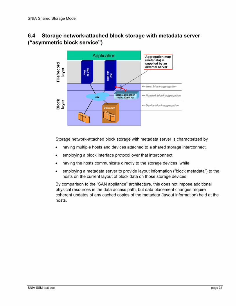
SNIA Shared Storage Model
SNIA-SSM-text.doc page 31
6.4 Storage network-attached block storage with metadata server (“asymmetric block service”)
Device block-aggregation
Network block-aggregation
Host block-aggregation
Device block-aggregation
Network block-aggregation
Host block-aggregation
Disk arrayHo
st w
ithLV
M
File
/reco
rdla
yer
Blo
ckla
yer
SNBlock-aggregationmetadata server
Host
,no
LVM
Aggregation map(metadata) issupplied by anexternal server
Aggregation map(metadata) issupplied by anexternal server
Application
Storage network-attached block storage with metadata server is characterized by
• having multiple hosts and devices attached to a shared storage interconnect,
• employing a block interface protocol over that interconnect,
• having the hosts communicate directly to the storage devices, while
• employing a metadata server to provide layout information (“block metadata”) to the hosts on the current layout of block data on those storage devices.
By comparison to the “SAN appliance” architecture, this does not impose additional physical resources in the data access path, but data placement changes require coherent updates of any cached copies of the metadata (layout information) held at the hosts.

SNIA Shared Storage Model
SNIA-SSM-text.doc page 32
6.5 Multi-site block storage
Device block-aggregation
Network block-aggregation
Host block-aggregation
Device block-aggregation
Network block-aggregation
Host block-aggregation
Disk array
SNSNAggregation
appliance
Host
. with
LVM
Application
Disk arrayDisk array
Aggregationappliance
Aggregationappliance
Aggregationappliance
Host
. with
LVM
Application
SN applianceSN appliance
WAN
SN applianceSN appliance
WANWAN
WAN
Host-to-hostHost-to-host
WANWAN
Host-to-hostHost-to-host
Functions: point-in-timecopy, caching, local & remote mirroring, …
Functions: point-in-timecopy, caching, local & remote mirroring, …
WAN
Device-to-deviceDevice-to-device
WANWAN
Device-to-deviceDevice-to-device
File
/reco
rdla
yer
Blo
ckla
yer
Multi-site block storage is characterized by the use of peer-to-peer protocols between like components of two or more systems at different sites to maintain data replicas at each site.
This addresses the increasing need for geographic separation and appropriate decoupling between two or more data sites. In turn, this can be used to enhance data availability in the presence of site disasters, while – with careful caching and update protocols – retaining the performance advantages of having access to a local copy of data. (This is particularly important in the presence of the larger propagation delays and lower bandwidths of long-haul networks.)
The peer-to-peer protocols can be implemented at several different levels, such as between pairs of logical volume managers, SAN appliances (e.g., remote mirroring boxes), and between storage devices themselves, such as disk arrays. The type of network used between the sites is frequently different than the network used within each site, so gateways or protocol conversion boxes may need to be employed to achieve the desired connectivity.
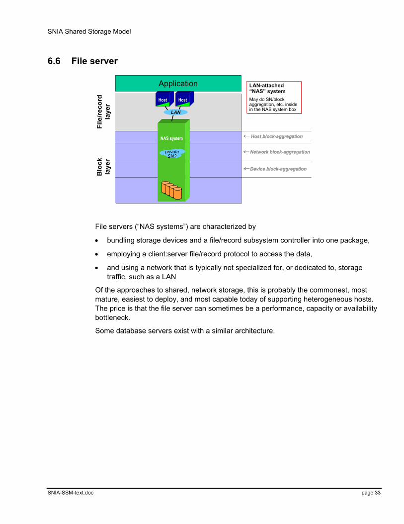
SNIA Shared Storage Model
SNIA-SSM-text.doc page 33
6.6 File server
Device block-aggregation
Network block-aggregation
Host block-aggregation
Device block-aggregation
Network block-aggregation
Host block-aggregationNAS system
HostHostFi
le/re
cord
laye
rB
lock
laye
r
LAN-attached“NAS” systemMay do SN/blockaggregation, etc. insidein the NAS system box
LAN-attached“NAS” systemMay do SN/blockaggregation, etc. insidein the NAS system box
Application
LAN
privateSN?
privateSN?
File servers (“NAS systems”) are characterized by
• bundling storage devices and a file/record subsystem controller into one package,
• employing a client:server file/record protocol to access the data,
• and using a network that is typically not specialized for, or dedicated to, storage traffic, such as a LAN
Of the approaches to shared, network storage, this is probably the commonest, most mature, easiest to deploy, and most capable today of supporting heterogeneous hosts. The price is that the file server can sometimes be a performance, capacity or availability bottleneck.
Some database servers exist with a similar architecture.
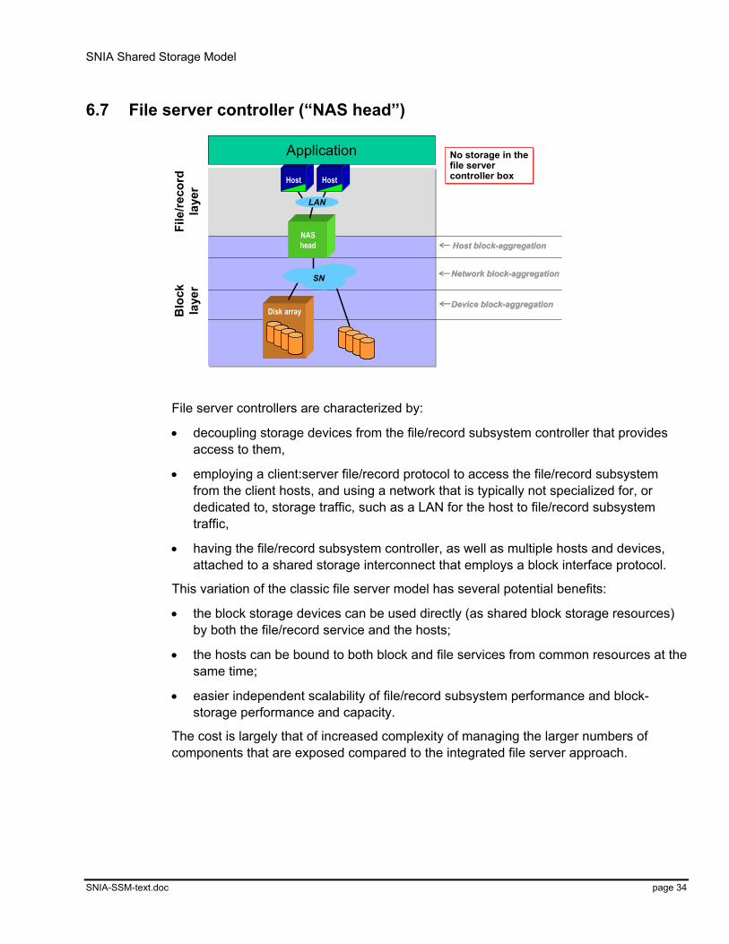
SNIA Shared Storage Model
SNIA-SSM-text.doc page 34
6.7 File server controller (“NAS head”)
Device block-aggregation
Network block-aggregation
Host block-aggregation
Device block-aggregation
Network block-aggregation
Host block-aggregationNAS head
Disk arrayDisk array
File
/reco
rdla
yer
Blo
ckla
yer
No storage in thefile server controller box
No storage in thefile server controller boxHostHost
LAN
Application
SNSN
File server controllers are characterized by:
• decoupling storage devices from the file/record subsystem controller that provides access to them,
• employing a client:server file/record protocol to access the file/record subsystem from the client hosts, and using a network that is typically not specialized for, or dedicated to, storage traffic, such as a LAN for the host to file/record subsystem traffic,
• having the file/record subsystem controller, as well as multiple hosts and devices, attached to a shared storage interconnect that employs a block interface protocol.
This variation of the classic file server model has several potential benefits:
• the block storage devices can be used directly (as shared block storage resources) by both the file/record service and the hosts;
• the hosts can be bound to both block and file services from common resources at the same time;
• easier independent scalability of file/record subsystem performance and block-storage performance and capacity.
The cost is largely that of increased complexity of managing the larger numbers of components that are exposed compared to the integrated file server approach.

SNIA Shared Storage Model
SNIA-SSM-text.doc page 35
6.8 NAS/file server metadata manager (“asymmetric file service”)
Device block-aggregation
Network block-aggregation
Host block-aggregation
Device block-aggregation
Network block-aggregation
Host block-aggregation
Disk array
File
/reco
rdla
yer
Blo
ckla
yer
Hosts get file meta-data from FS/NAS controller, thenaccess the data directly
Hosts get file meta-data from FS/NAS controller, thenaccess the data directly
Host
. with
LVM
Filemetadata
Blockaccesses
FS controller canalso be NAS serverFS controller canalso be NAS server
HostLAN
FS controller canalso be NAS serverFS controller canalso be NAS server
HostLAN
HostHostLAN
SNSN
Application
File system metadata
NAS/file server metadata managers are characterized by the following (shown applying to the left-hand host in the figure here):
• multiple hosts and devices attached to a shared storage interconnect that employs a block interface protocol;
• a separate file system metadata server that maintains layout information for files (“file metadata”), and provides this to the hosts on request;
• hosts that communicate with the file system metadata server (using an extended client:server file/record protocol ) to obtain layout information for the files they wish to access, and then access directly across the shared storage interconnect using a block interface protocol.
This variation offers the performance advantage of direct access to the block storage devices across the storage network with the data sharing advantages of file servers. The performance advantages are largely those of high-speed data traffic, and apply only as long as the rate of metadata updates and the amount of cache coherency traffic is not “too high”.
In addition, the file/record metadata server can also do double-duty and act as a traditional file/record subsystem controller (“NAS head”) for hosts that do not support the extended client/server metadata protocols.
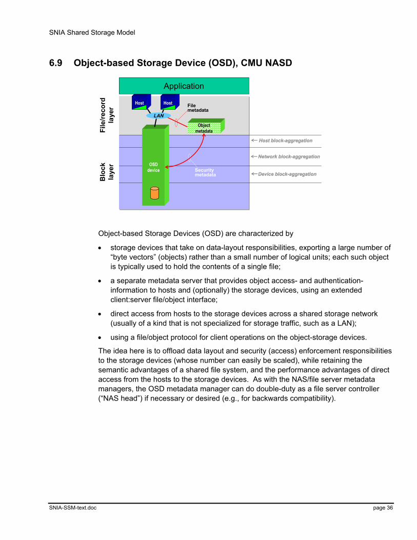
SNIA Shared Storage Model
SNIA-SSM-text.doc page 36
6.9 Object-based Storage Device (OSD), CMU NASD
Device block-aggregation
Network block-aggregation
Host block-aggregation
Device block-aggregation
Network block-aggregation
Host block-aggregation
OSDdevice
File
/reco
rdla
yer
Blo
ckla
yer
HostHost
Object metadata
HostHost
Application
LAN
Securitymetadata
Filemetadata
Object-based Storage Devices (OSD) are characterized by
• storage devices that take on data-layout responsibilities, exporting a large number of “byte vectors” (objects) rather than a small number of logical units; each such object is typically used to hold the contents of a single file;
• a separate metadata server that provides object access- and authentication-information to hosts and (optionally) the storage devices, using an extended client:server file/object interface;
• direct access from hosts to the storage devices across a shared storage network (usually of a kind that is not specialized for storage traffic, such as a LAN);
• using a file/object protocol for client operations on the object-storage devices.
The idea here is to offload data layout and security (access) enforcement responsibilities to the storage devices (whose number can easily be scaled), while retaining the semantic advantages of a shared file system, and the performance advantages of direct access from the hosts to the storage devices. As with the NAS/file server metadata managers, the OSD metadata manager can do double-duty as a file server controller (“NAS head”) if necessary or desired (e.g., for backwards compatibility).

SNIA Shared Storage Model
SNIA-SSM-text.doc page 37
7 Summary and conclusions
File/record layerFile/record layer
Database(dbms)
File system(FS)
Database(dbms)
Database(dbms)
File system(FS)
File system(FS)
Stor
age
dom
ain
Block layerBlock layer
Storage devices (disks, …)Storage devices (disks, …)
Serv
ices
Serv
ices
Dis
cove
ry, m
onito
ring
Dis
cove
ry, m
onito
ring
Res
ourc
e m
gmt,
conf
igur
atio
nR
esou
rce
mgm
t, co
nfig
urat
ion
Sec
urity
, bill
ing
Sec
urity
, billi
ngR
edun
danc
y m
gmt (
back
up, …
)R
edun
danc
y m
gmt (
back
up, …
)H
igh
avai
labi
lity
(fail-
over
, …)
Hig
h av
aila
bilit
y (fa
il-ov
er, …
)C
apac
ity p
lann
ing
Cap
acity
pla
nnin
g
Serv
ices
Serv
ices
Dis
cove
ry, m
onito
ring
Dis
cove
ry, m
onito
ring
Res
ourc
e m
gmt,
conf
igur
atio
nR
esou
rce
mgm
t, co
nfig
urat
ion
Sec
urity
, bill
ing
Sec
urity
, billi
ngR
edun
danc
y m
gmt (
back
up, …
)R
edun
danc
y m
gmt (
back
up, …
)H
igh
avai
labi
lity
(fail-
over
, …)
Hig
h av
aila
bilit
y (fa
il-ov
er, …
)C
apac
ity p
lann
ing
Cap
acity
pla
nnin
g
Dis
cove
ry, m
onito
ring
Dis
cove
ry, m
onito
ring
Res
ourc
e m
gmt,
conf
igur
atio
nR
esou
rce
mgm
t, co
nfig
urat
ion
Sec
urity
, bill
ing
Sec
urity
, billi
ngR
edun
danc
y m
gmt (
back
up, …
)R
edun
danc
y m
gmt (
back
up, …
)H
igh
avai
labi
lity
(fail-
over
, …)
Hig
h av
aila
bilit
y (fa
il-ov
er, …
)C
apac
ity p
lann
ing
Cap
acity
pla
nnin
g
Application
Network
Host
DeviceBlock aggregation
Network
Host
DeviceBlock aggregation
The SNIA Shared Storage Model is a simple and powerful model for describing shared storage architectures. We believe this model will be valuable to several groups:
• Vendors – to place products in the space of architectures, and clarify product differences.
• Customers – to understand vendor offerings better.
• The storage industry as a whole – as a basis for common definitions, communication, understanding, and increased interoperability.
We hope you, too, find it useful.
7.1 Status
The SNIA Shared Storage model is still a work in progress. The SNIA Technical Council would appreciate feedback on it, and particularly on those occasions where the model fails to cover an architecture or design, or when it could do so more elegantly. You can send us feedback via email to [email protected], or through the SNIA technical director at [email protected].