Embed Size (px)
Citation preview
IJRET: International Journal of Research in Engineering and Technology eISSN: 2319-1163 | pISSN: 2321-7308
_______________________________________________________________________________________
Volume: 03 Special Issue: 16 | ICPECDM-2014 | Dec-2014, Available @ http://www.ijret.org 89
SHEAR STRENGTH OF RC DEEP BEAM PANELS – A REVIEW
J. Leon Raj1, G. Appa Rao
2
1Research Scholar; Department of Civil Engineering, Indian Institute of Technology Madras, Chennai-600036
2Professor, Department of Civil Engineering, Indian Institute of Technology Madras, Chennai-600036
Abstract Behaviour of RC beam panels is influenced by several factors. An alternative for conventional beam is 3D steel wire precast panel
to behave as deep beam in various locations of RC building systems. Understanding the influence of factors involved on behaviour
and strength is needed. The factors to be discussed include; compressive strength of concrete, percentage of tension
reinforcement, quantity and distribution of vertical and horizontal web reinforcement, aggregate interlock, shear span-to-depth
ratio, distribution of loading, side cover, and depth of beam. The influence of above parameters on the shear strength of reinforced concrete deep beams has been reviewed.
Keywords: Deep beams, Shear strength, 3D panels, distribution of reinforcement.
--------------------------------------------------------------------***------------------------------------------------------------------
1. INTRODUCTION
A major challenge in every tall building construction is to
achieve adequate column free space in the lowermost storey
either for parking or storage facility. To achieve sufficient
dwelling room size as per architectural design in the upper stories, vertical element so-called floating column is
endowed. Its terminal level rests on the transfer girder which
acts as a point load. In view of ample shear strength, deep
beams are primarily recommended as transfer girders. These
members transfer loads through loading face to supports in
the transverse direction. The deep horizontal members
predominantly fail in shear rather than flexure. These beams
are characterized with small span-to-depth ratio. Pile caps,
corbel, brackets, foundation walls and off-shore structures
are few examples of RC deep beams.
Web reinforcement plays a vital role in enhancing the shear capacity and mode of failure. It is unclear that IS 456 2000
provisions for minimum web reinforcement ensures ductile
failure and inherently satisfies the serviceability criteria. In
addition, there is a lack of comprehensive provision for the
design and prediction of shear-capacity of RC deep beams.
Motivation for this review is to understand the influencing
parameters of deep beams on strength and serviceability
aspects.
3D steel wire sandwich panels enunciated as light weight
panels comprise of concrete-polystyrene-concrete layers. Either side of the polystyrene, concrete cover is reinforced
with steel wire mesh. 3D panels can be used as an
alternative for structural members such as walls, beams and
slabs. Advantages over the conventional construction system
are eco-friendly, light weight, fast construction, cost
effective, thermally and acoustically insulated. In addition to
the aforementioned conspicuous advantages, the sandwich
panel has the following advantages in structural behaviour.
Hereby, advantages of 3D panel in structural behaviour
aspect are explained in comparison with deep beams and
shear walls vis-a-vis minimum percentage of web
reinforcement mentioned in code. As per ACI Committee
2008, minimum percentage of horizontal and vertical web
reinforcement for deep beams is 0.15 and 0.25. Minimum
web reinforcement for shear wall in orthogonal directions is 0.25% (Murty, 2005).
3D panels have well distributed steel wire mesh inherently
satisfying the minimum web reinforcement criteria. Integral
and diaphragms action are two major research issues to be
studied. Steel wire meshes on the either side of the
polystyrene are fastened with inclined or 90o steel
connectors can accomplish the integral action (Carbonari et
al. 2012).
2. DEFINITION OF RC DEEP BEAMS
A beam is defined as a deep beam in which either the clear
span is equal to or less than four times the overall depth, or the concentrated loads are within a distance equal to or less
than two times the depth from the face of support (ACI
Committee 318, 2008).
According to IS 456-2000 a beam shall be deemed to be a
deep beam when the ratio of effective span-to-overall depth,
is less than:
1)2.0, for simply supported beam; and
2)2.5, for a continuous beam
Though different codes define deep beams in different clear
span-to-depth ratios, as a general rule deep beams are
recognized by their relatively small span-to-depth ratio.
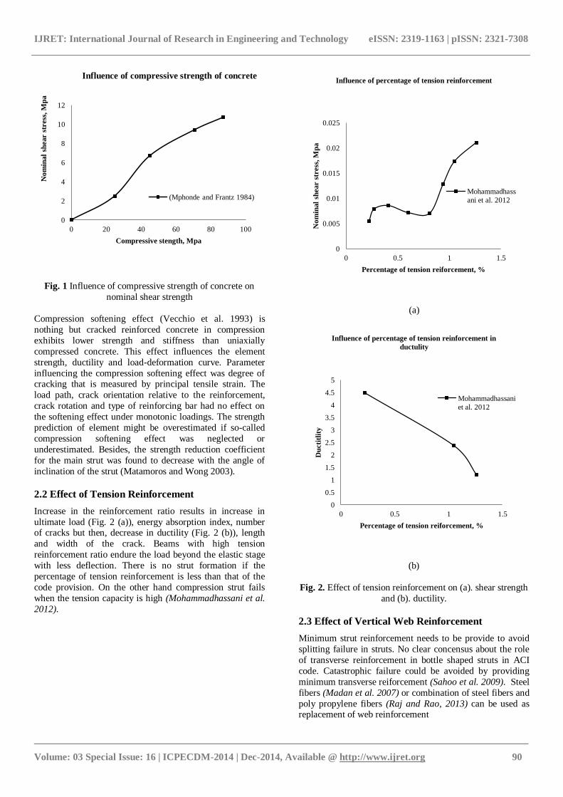
2.1 Effect of Compressive Strength of Concrete
Compressive strength of concrete has a predominant role in
structural strength of deep beams. As show in Fig. 1, compressive strength of concrete increases the nominal
shear stress (Mphonde and Frantz, 1984).
IJRET: International Journal of Research in Engineering and Technology eISSN: 2319-1163 | pISSN: 2321-7308
_______________________________________________________________________________________
Volume: 03 Special Issue: 16 | ICPECDM-2014 | Dec-2014, Available @ http://www.ijret.org 90
Fig. 1 Influence of compressive strength of concrete on
nominal shear strength
Compression softening effect (Vecchio et al. 1993) is
nothing but cracked reinforced concrete in compression
exhibits lower strength and stiffness than uniaxially
compressed concrete. This effect influences the element
strength, ductility and load-deformation curve. Parameter
influencing the compression softening effect was degree of cracking that is measured by principal tensile strain. The
load path, crack orientation relative to the reinforcement,
crack rotation and type of reinforcing bar had no effect on
the softening effect under monotonic loadings. The strength
prediction of element might be overestimated if so-called
compression softening effect was neglected or
underestimated. Besides, the strength reduction coefficient
for the main strut was found to decrease with the angle of
inclination of the strut (Matamoros and Wong 2003).
2.2 Effect of Tension Reinforcement
Increase in the reinforcement ratio results in increase in
ultimate load (Fig. 2 (a)), energy absorption index, number of cracks but then, decrease in ductility (Fig. 2 (b)), length
and width of the crack. Beams with high tension
reinforcement ratio endure the load beyond the elastic stage
with less deflection. There is no strut formation if the
percentage of tension reinforcement is less than that of the
code provision. On the other hand compression strut fails
when the tension capacity is high (Mohammadhassani et al.
2012).
(a)
(b)
Fig. 2. Effect of tension reinforcement on (a). shear strength
and (b). ductility.
2.3 Effect of Vertical Web Reinforcement
Minimum strut reinforcement needs to be provide to avoid
splitting failure in struts. No clear concensus about the role
of transverse reinforcement in bottle shaped struts in ACI
code. Catastrophic failure could be avoided by providing
minimum transverse reiforcement (Sahoo et al. 2009). Steel
fibers (Madan et al. 2007) or combination of steel fibers and
poly propylene fibers (Raj and Rao, 2013) can be used as replacement of web reinforcement
0
2
4
6
8
10
12
0 20 40 60 80 100
No
min
al
shear s
tress
, M
pa
Compressive stength, Mpa
Influence of compressive strength of concrete
(Mphonde and Frantz 1984)
0
0.005
0.01
0.015
0.02
0.025
0 0.5 1 1.5
No
min
al
shear s
tress
, M
pa
Percentage of tension reiforcement, %
Influence of percentage of tension reinforcement
Mohammadhass
ani et al. 2012
0
0.5
1
1.5
2
2.5
3
3.5
4
4.5
5
0 0.5 1 1.5
Du
cti
tlit
y
Percentage of tension reiforcement, %
Influence of percentage of tension reinforcement in
ductulity
Mohammadhassani
et al. 2012
IJRET: International Journal of Research in Engineering and Technology eISSN: 2319-1163 | pISSN: 2321-7308
_______________________________________________________________________________________
Volume: 03 Special Issue: 16 | ICPECDM-2014 | Dec-2014, Available @ http://www.ijret.org 91
2.4 Effect of Horizontal Web Reinforcement
The horizontal web reinforcement at close spacing near the
bottom faces of the beam has been observed to be effective
(Smith and Vantsiotis 1983). The shear strength increases
with increase in the percentage of web reinforcement
(Madan et al. 2007). Both the vertical and horizontal web
reinforcement are efficient in resisting the shear capacity of deep beams, but the horizontal shear reinforcement is most
effective when aligned perpendicular to the major axis of the
diagonal crack (Arabzadeh et al. 2011). Provision of shear
reinforcement within the middle region of the shear span can
improve the ultimate shear strength of deep beam (Aguilar
et al. 2003). On the other hand the horizontal web
reinforcement is less effective in providing shear strength
than the vertical web reinforcement (ACI Committee 2008).
Minimum percentage of web reinforcement for strength and
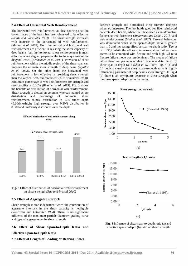
serviceability is 0.30% (Birrcher et al. 2013). Fig. 3 shows
the benefits of distribution of horizontal web reinforcement.
Shear strength is plotted on columns whereas; named as per distribution and percentage of horizontal shear
reinforcement. 0.30% distribution in 0.30 times depth
(0.30d) exhibits high strength over 0.20% distribution in
0.30d and uniformly distributed over the depth.
Fig. 3 Effect of distribution of horizontal web reinforcement
on shear strength (Rao and Prasad 2010)
2.5 Effect of Aggregate Interlock
Shear strength is size independent when the contribution of aggregate interlock in the shear capacity is negligible
(Walraven and Lehwalter 1994). There is no significant
influence of the maximum particle diameter, grading curve
and type of aggregate on the shear strength.
2.6 Effect of Shear Span-to-Depth Ratio and
Effective Span-to-Depth Ratio
Reserve strength and normalised shear strength decrease
when a/d increases. The fact holds good for fiber reinforced
concrete deep beams, where the fibers used as an alternative
for tension reinforcement (Andermatt and Lubell, 2013) and
web reinforcement (Madan et al. 2007). Flexural behaviour
was dominated when shear span-to-depth ratio is greater than 1.0 and increasing effective span-to-depth ratio (Tan et
al. 1995). While the a/d ratio increases, shear failure mode
seems to be combined with flexure and with high le/d ratio
flexure failure mode was predominant. The modes of failure
either shear compression or shear tension is determined by
shear span-to-depth ratio (Shin et al. 1999). Fig. 4 (a) and
(b) depicts clearly that shear span-to-depth ratio is highly
influencing parameter of deep beams shear strength. In Fig.4
(a) there is an asymptotic decrease in shear strength when
the shear span-to-depth ratio increases.
(a)
(b)
Fig. 4 Influence of shear span-to-depth ratio (a) and
effective span-to-depth (b) ratio on shear strength
2.7 Effect of Length of Loading or Bearing Plates
5.07
7.72
5.13
8.51
0.20% 0.30% 0.20% in 0.3d 0.30% in 0.3d
Effect of distibution of web reinforcement along
depth
Nominal shear strength, Mpa 1.00
3.00
5.00
7.00
9.00
11.00
13.00
15.00
0 1 2 3
No
min
al
shear s
tress
, M
pa
a/d ratio
Shear strength vs. a/d ratio
(Tan et al. 1995).
1.00
3.00
5.00
7.00
9.00
11.00
13.00
15.00
0 2 4 6
No
min
al
shear s
tress
, M
pa
ln/d ratio
Shear strength vs. ln/d ratio
(Tan et al. 1995).
IJRET: International Journal of Research in Engineering and Technology eISSN: 2319-1163 | pISSN: 2321-7308
_______________________________________________________________________________________
Volume: 03 Special Issue: 16 | ICPECDM-2014 | Dec-2014, Available @ http://www.ijret.org 92
A CCC (Compression-Compression-Compression) or CCT (Compression-Compression-Tension) node, tri-axially confined by
surrounding concrete, can achieve bearing stresses that are much higher than the compressive strength of concrete. No evidence of
reduction in shear strength when there was a reduction in width of load or support-bearing plate (Tuchscherer et al. 2010).
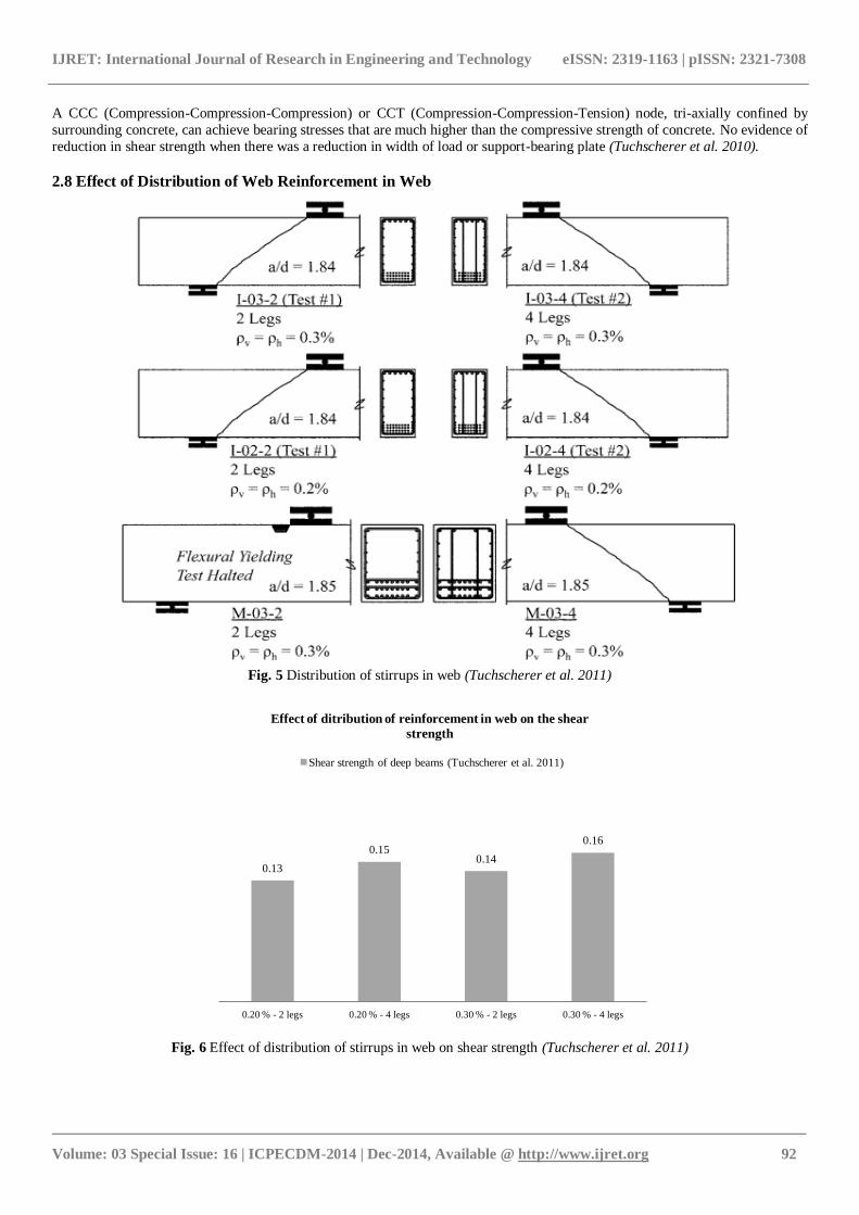
2.8 Effect of Distribution of Web Reinforcement in Web
Fig. 5 Distribution of stirrups in web (Tuchscherer et al. 2011)
Fig. 6 Effect of distribution of stirrups in web on shear strength (Tuchscherer et al. 2011)
0.13
0.15 0.14
0.16
0.20 % - 2 legs 0.20 % - 4 legs 0.30 % - 2 legs 0.30 % - 4 legs
Effect of ditribution of reinforcement in web on the shear
strength
Shear strength of deep beams (Tuchscherer et al. 2011)
IJRET: International Journal of Research in Engineering and Technology eISSN: 2319-1163 | pISSN: 2321-7308
_______________________________________________________________________________________
Volume: 03 Special Issue: 16 | ICPECDM-2014 | Dec-2014, Available @ http://www.ijret.org 93
Beams with and without distributed stirrups across the web
is shown in fig. 5. Closely spaced stirrups in web did not
enhance shear capacity or serviceability performance
(Tuchscherer et al. 2011). Fig. 6 shows the shear strength of
four tests on the first two beams of Fig. 5. Besides, Fig. 6
gives a clear depiction about the effect of distribution of stirrups on the shear strength. Columns in Fig. 6 are named
as percentage of web reinforcement and legs of stirrups.
Web reinforcement had no influence on the magnitude of
diagonal cracking strength (Zhang and Tan 2007). Web
reinforcement provided vertically was most effective than
the horizontal. Orthogonal reinforcement exhibited good
control over diagonal cracking, enhanced shear strength and
increased beam stiffness (Tan et al. 1997).
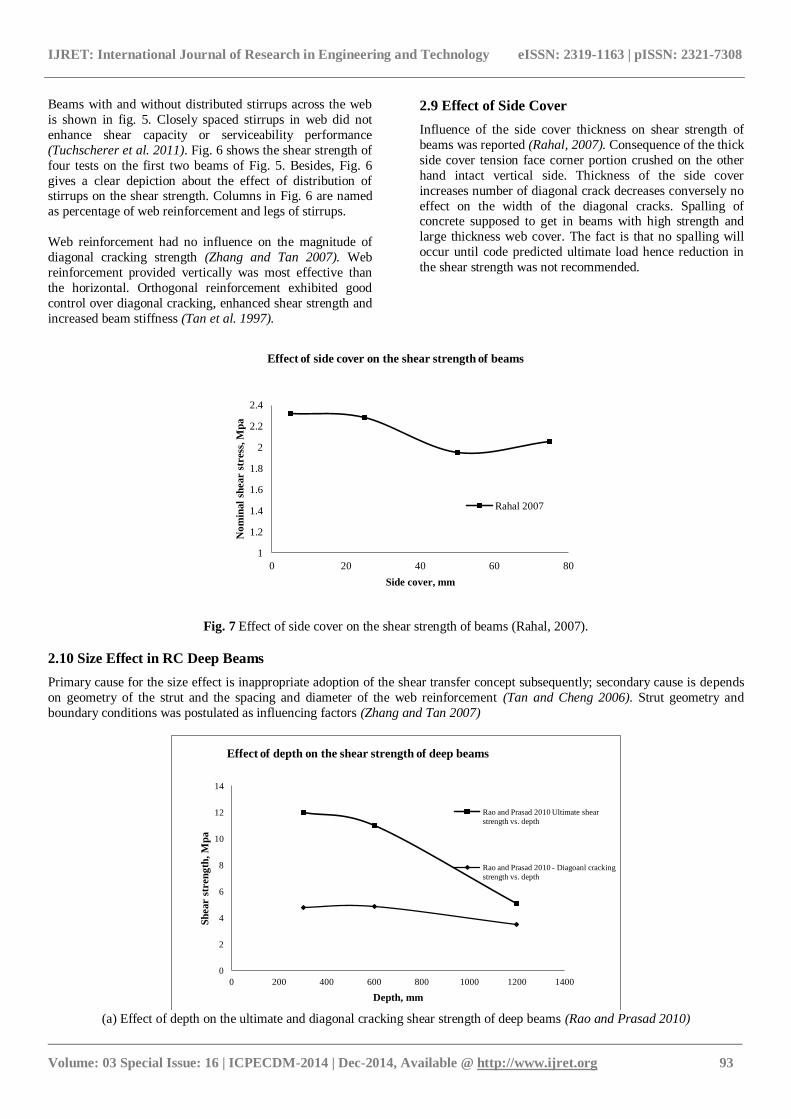
2.9 Effect of Side Cover
Influence of the side cover thickness on shear strength of
beams was reported (Rahal, 2007). Consequence of the thick
side cover tension face corner portion crushed on the other
hand intact vertical side. Thickness of the side cover
increases number of diagonal crack decreases conversely no
effect on the width of the diagonal cracks. Spalling of concrete supposed to get in beams with high strength and
large thickness web cover. The fact is that no spalling will
occur until code predicted ultimate load hence reduction in
the shear strength was not recommended.
Fig. 7 Effect of side cover on the shear strength of beams (Rahal, 2007).
2.10 Size Effect in RC Deep Beams
Primary cause for the size effect is inappropriate adoption of the shear transfer concept subsequently; secondary cause is depends
on geometry of the strut and the spacing and diameter of the web reinforcement (Tan and Cheng 2006). Strut geometry and
boundary conditions was postulated as influencing factors (Zhang and Tan 2007)
(a) Effect of depth on the ultimate and diagonal cracking shear strength of deep beams (Rao and Prasad 2010)
1
1.2
1.4
1.6
1.8
2
2.2
2.4
0 20 40 60 80
No
min
al
shear s
tress
, M
pa
Side cover, mm
Effect of side cover on the shear strength of beams
Rahal 2007
0
2
4
6
8
10
12
14
0 200 400 600 800 1000 1200 1400
Sh
ear s
tren
gth
, M
pa
Depth, mm
Effect of depth on the shear strength of deep beams
Rao and Prasad 2010 Ultimate shear
strength vs. depth
Rao and Prasad 2010 - Diagoanl cracking
strength vs. depth
IJRET: International Journal of Research in Engineering and Technology eISSN: 2319-1163 | pISSN: 2321-7308
_______________________________________________________________________________________
Volume: 03 Special Issue: 16 | ICPECDM-2014 | Dec-2014, Available @ http://www.ijret.org 94
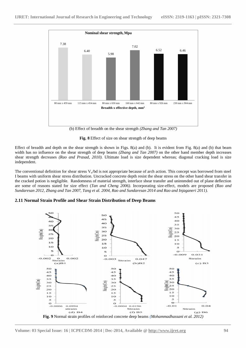
(b) Effect of breadth on the shear strength (Zhang and Tan 2007)
Fig. 8 Effect of size on shear strength of deep beams
Effect of breadth and depth on the shear strength is shown in Figs. 8(a) and (b). It is evident from Fig. 8(a) and (b) that beam
width has no influence on the shear strength of deep beams (Zhang and Tan 2007) on the other hand member depth increases
shear strength decreases (Rao and Prasad, 2010). Ultimate load is size dependent whereas; diagonal cracking load is size
independent.
The conventional definition for shear stress Vu/bd is not appropriate because of arch action. This concept was borrowed from steel
I beams with uniform shear stress distribution. Uncracked concrete depth resist the shear stress on the other hand shear transfer in
the cracked potion is negligible. Randomness of material strength, interface shear transfer and unintended out of plane deflection
are some of reasons stated for size effect (Tan and Cheng 2006). Incorporating size-effect, models are proposed (Rao and
Sundaresan 2012, Zhang and Tan 2007, Tang et al. 2004, Rao and Sundaresan 2014 and Rao and Injaganeri 2011).
2.11 Normal Strain Profile and Shear Strain Distribution of Deep Beams
Fig. 9 Normal strain profiles of reinforced concrete deep beams (Mohammadhassani et al. 2012)
7.38
6.40 5.98
7.02 6.52 6.46
80 mm x 459 mm 115 mm x 454 mm 80 mm x 650 mm 160 mm x 642 mm 80 mm x 926 mm 230 mm x 904 mm
Breadth x effective depth, mm2
Nominal shear strength, Mpa
IJRET: International Journal of Research in Engineering and Technology eISSN: 2319-1163 | pISSN: 2321-7308
_______________________________________________________________________________________
Volume: 03 Special Issue: 16 | ICPECDM-2014 | Dec-2014, Available @ http://www.ijret.org 95
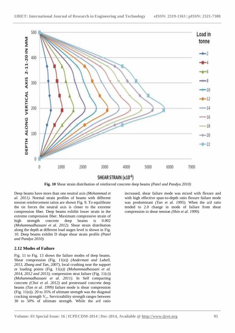
Fig. 10 Shear strain distribution of reinforced concrete deep beams (Patel and Pandya 2010)
Deep beams have more than one neutral axis (Mohammad et
al. 2011). Normal strain profiles of beams with different
tension reinforcement ratios are shown Fig. 9. To equilibrate
the tie forces the neutral axis is closer to the extreme
compression fiber. Deep beams exhibit lower strain in the
extreme compression fiber. Maximum compressive strain of
high strength concrete deep beams is 0.002
(Mohammadhassani et al. 2012). Shear strain distribution
along the depth at different load stages level is shown in Fig. 10. Deep beams exhibit D shape shear strain profile (Patel
and Pandya 2010).
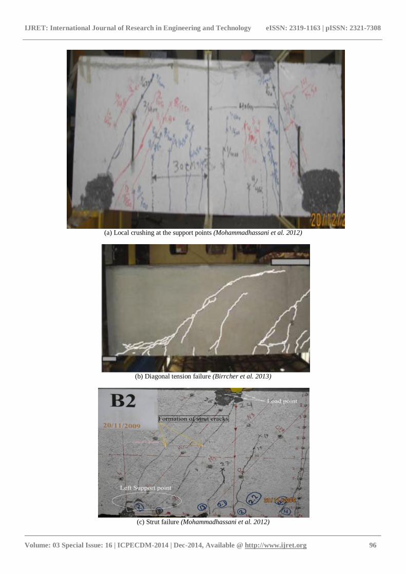
2.12 Modes of Failure
Fig. 11 to Fig. 13 shows the failure modes of deep beams.
Shear compression (Fig. 11(e)) (Andermatt and Lubell,
2013, Zhang and Tan, 2007), local crushing near the support
or loading points (Fig. 11(a)) (Mohammadhassani et al.
2014, 2012 and 2013), compression strut failure (Fig. 11(c))
(Mohammadhassani et al. 2011). In Self compacting
concrete (Choi et al. 2012) and prestressed concrete deep
beams (Tan et al. 1999) failure mode is shear compression
(Fig. 11(e)). 20 to 35% of ultimate strength was the diagonal
cracking strength Vcr. Serviceability strength ranges between 30 to 50% of ultimate strength. While the a/d ratio
increased, shear failure mode was mixed with flexure and
with high effective span-to-depth ratio flexure failure mode
was predominant (Tan et al. 1995). When the a/d ratio
tended to 2.0 change in mode of failure from shear
compression to shear tension (Shin et al. 1999).
IJRET: International Journal of Research in Engineering and Technology eISSN: 2319-1163 | pISSN: 2321-7308
_______________________________________________________________________________________
Volume: 03 Special Issue: 16 | ICPECDM-2014 | Dec-2014, Available @ http://www.ijret.org 96
(a) Local crushing at the support points (Mohammadhassani et al. 2012)
(b) Diagonal tension failure (Birrcher et al. 2013)
(c) Strut failure (Mohammadhassani et al. 2012)
IJRET: International Journal of Research in Engineering and Technology eISSN: 2319-1163 | pISSN: 2321-7308
_______________________________________________________________________________________
Volume: 03 Special Issue: 16 | ICPECDM-2014 | Dec-2014, Available @ http://www.ijret.org 97
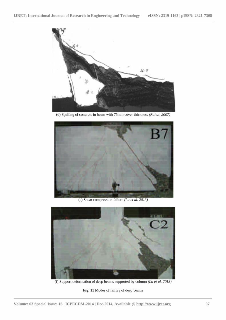
(d) Spalling of concrete in beam with 75mm cover thickness (Rahal, 2007)
(e) Shear compression failure (Lu et al. 2013)
(f) Support deformation of deep beams supported by column (Lu et al. 2013)
Fig. 11 Modes of failure of deep beams
IJRET: International Journal of Research in Engineering and Technology eISSN: 2319-1163 | pISSN: 2321-7308
_______________________________________________________________________________________
Volume: 03 Special Issue: 16 | ICPECDM-2014 | Dec-2014, Available @ http://www.ijret.org 98
Diagonal tension failure (Fig. 2 (b)) of deep beams affirmed by no concrete crushing was observed in critical shear span region.
Axial stiffness of support plates are more than concrete columns. Consequently, support deformation (Fig. 2 (f)) of deep beams
supported by column is more when compared to local crushing near support. Strut failure is the common mode of failure in deep
beams. Spalling of concrete may occur due to excessive cover as show in Fig. 2 (d).
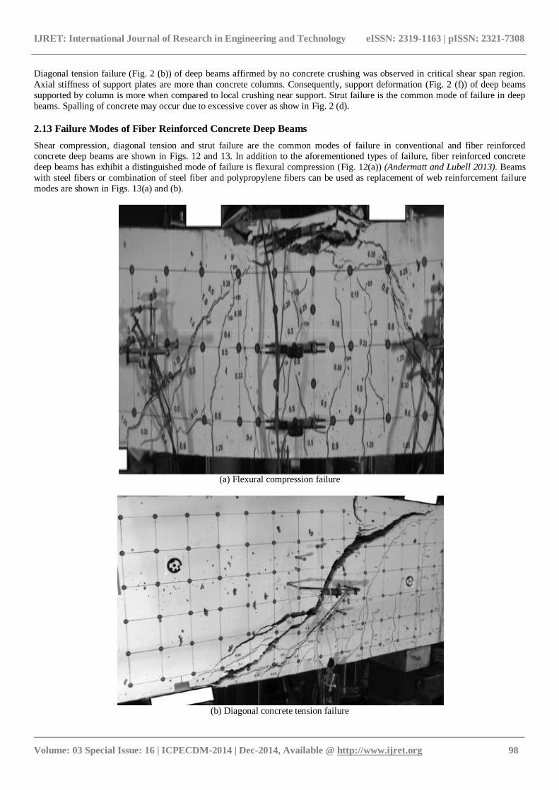
2.13 Failure Modes of Fiber Reinforced Concrete Deep Beams
Shear compression, diagonal tension and strut failure are the common modes of failure in conventional and fiber reinforced concrete deep beams are shown in Figs. 12 and 13. In addition to the aforementioned types of failure, fiber reinforced concrete
deep beams has exhibit a distinguished mode of failure is flexural compression (Fig. 12(a)) (Andermatt and Lubell 2013). Beams
with steel fibers or combination of steel fiber and polypropylene fibers can be used as replacement of web reinforcement failure
modes are shown in Figs. 13(a) and (b).
(a) Flexural compression failure
(b) Diagonal concrete tension failure
IJRET: International Journal of Research in Engineering and Technology eISSN: 2319-1163 | pISSN: 2321-7308
_______________________________________________________________________________________
Volume: 03 Special Issue: 16 | ICPECDM-2014 | Dec-2014, Available @ http://www.ijret.org 99
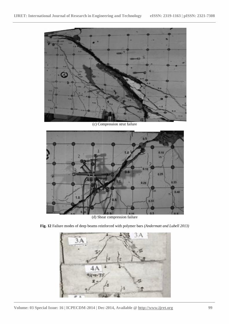
(c) Compression strut failure
(d) Shear compression failure
Fig. 12 Failure modes of deep beams reinforced with polymer bars (Andermatt and Lubell 2013)
IJRET: International Journal of Research in Engineering and Technology eISSN: 2319-1163 | pISSN: 2321-7308
_______________________________________________________________________________________
Volume: 03 Special Issue: 16 | ICPECDM-2014 | Dec-2014, Available @ http://www.ijret.org 100
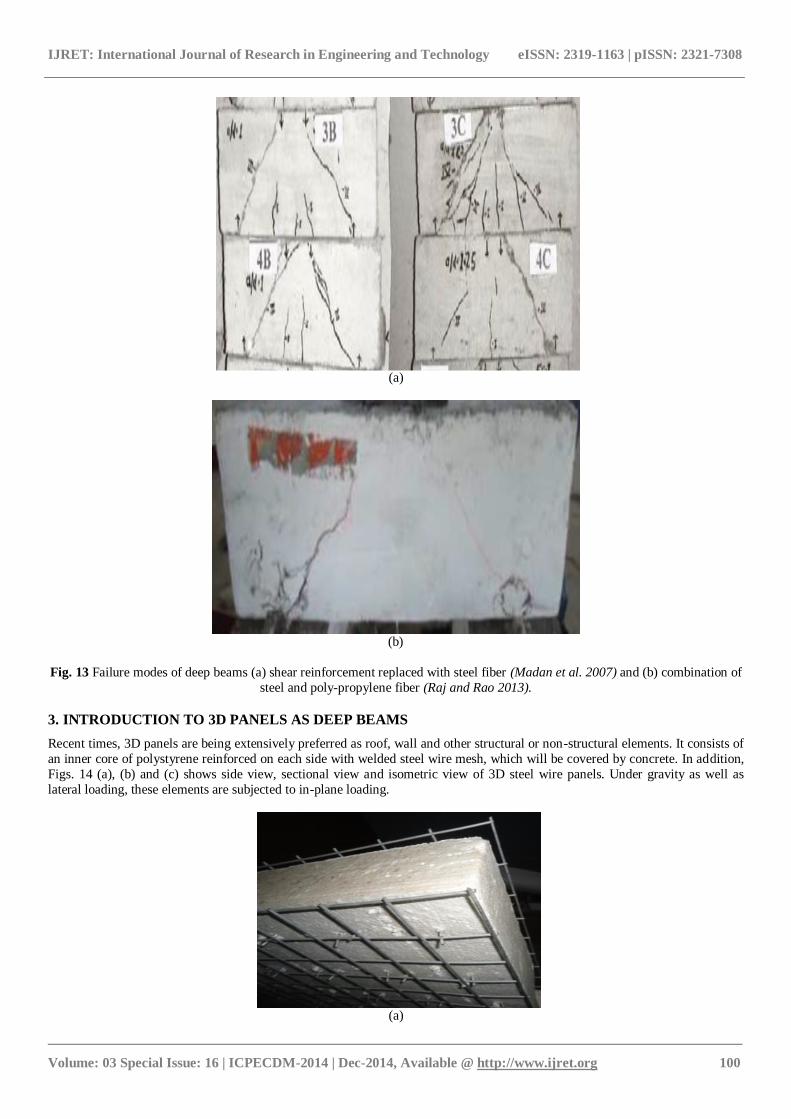
(a)
(b)
Fig. 13 Failure modes of deep beams (a) shear reinforcement replaced with steel fiber (Madan et al. 2007) and (b) combination of
steel and poly-propylene fiber (Raj and Rao 2013).
3. INTRODUCTION TO 3D PANELS AS DEEP BEAMS
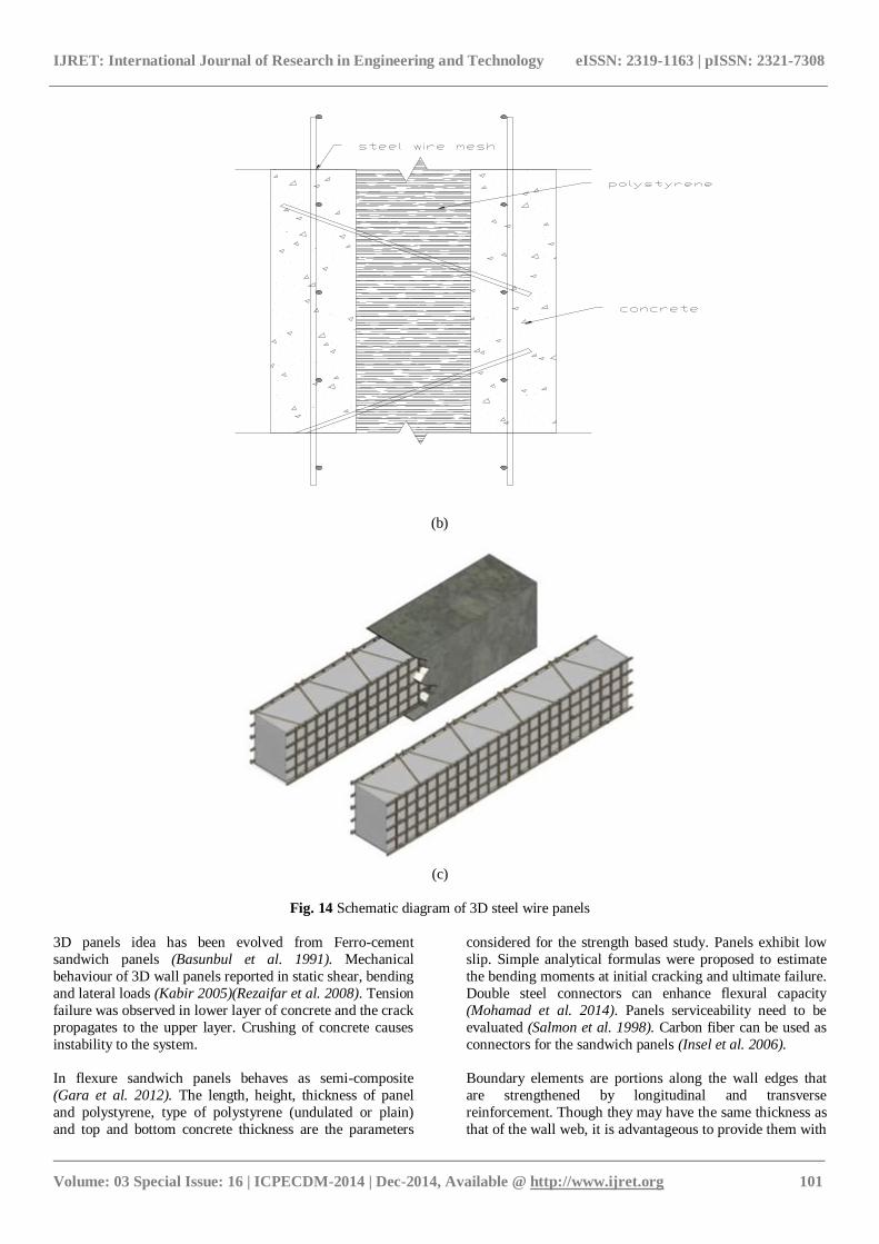
Recent times, 3D panels are being extensively preferred as roof, wall and other structural or non-structural elements. It consists of
an inner core of polystyrene reinforced on each side with welded steel wire mesh, which will be covered by concrete. In addition,
Figs. 14 (a), (b) and (c) shows side view, sectional view and isometric view of 3D steel wire panels. Under gravity as well as
lateral loading, these elements are subjected to in-plane loading.
(a)
IJRET: International Journal of Research in Engineering and Technology eISSN: 2319-1163 | pISSN: 2321-7308
_______________________________________________________________________________________
Volume: 03 Special Issue: 16 | ICPECDM-2014 | Dec-2014, Available @ http://www.ijret.org 101
(b)
(c)
Fig. 14 Schematic diagram of 3D steel wire panels
3D panels idea has been evolved from Ferro-cement
sandwich panels (Basunbul et al. 1991). Mechanical
behaviour of 3D wall panels reported in static shear, bending
and lateral loads (Kabir 2005)(Rezaifar et al. 2008). Tension
failure was observed in lower layer of concrete and the crack
propagates to the upper layer. Crushing of concrete causes
instability to the system.
In flexure sandwich panels behaves as semi-composite
(Gara et al. 2012). The length, height, thickness of panel
and polystyrene, type of polystyrene (undulated or plain)
and top and bottom concrete thickness are the parameters
considered for the strength based study. Panels exhibit low
slip. Simple analytical formulas were proposed to estimate
the bending moments at initial cracking and ultimate failure.
Double steel connectors can enhance flexural capacity
(Mohamad et al. 2014). Panels serviceability need to be
evaluated (Salmon et al. 1998). Carbon fiber can be used as
connectors for the sandwich panels (Insel et al. 2006).
Boundary elements are portions along the wall edges that
are strengthened by longitudinal and transverse
reinforcement. Though they may have the same thickness as
that of the wall web, it is advantageous to provide them with
IJRET: International Journal of Research in Engineering and Technology eISSN: 2319-1163 | pISSN: 2321-7308
_______________________________________________________________________________________
Volume: 03 Special Issue: 16 | ICPECDM-2014 | Dec-2014, Available @ http://www.ijret.org 102
greater thickness (Medhekar and Jain 1993). Boundary
elements can be used to enhance the flexural capacity
(Mostofinejad and Mohammadi Anaei 2012). To increase
the stiffness and to reduce the restrictions regarding the
service limit state, it is important to design an efficient
reinforced connection between the slabs and their supporting element. The overall contribution of the connectors to the
flexural stiffness of the slab is small (Carbonari et al. 2012).
4. CONCLUSION
In general, code provisions for beam capacity equations are
conservative. Significantly influencing parameters are shear
span-to-depth ratio, horizontal web reinforcement, vertical
web reinforcement, support and load bearing plates,
distribution of web reinforcement along depth, compressive
strength and tension reinforcement. Least influencing
parameters are width of the beam, bottom cover, side cover,
aggregate size and distribution of vertical stirrups in web.
Diaphragm action of 3D panels needs to be experimentally evaluated.
REFERENCES
[1] Aguilar, G., Matamoros, A. B., Parra-montesinos, G.
J., Ramírez, J. A., and Wight, J. K. (2003).
“Experimental Evaluation of Design Procedures for
Shear Strength of Deep Reinforced Concrete
Beams.” (99), 539–548.
[2] Andermatt, M. F., and Lubell, A. S. (2013).
“Behavior of Concrete Deep Beams Reinforced with
Internal Fiber-Reinforced Polymer — Experimental
Study.” ACI Structural Journal, 47(110), 585–594.
[3] Arabzadeh, A., Aghayari, R., and Rahai, A. R. (2011). “International Journal of Civil Engineering
Investigation of experimental and analytical shear
strength of reinforced concrete deep beams.” 9(3).
[4] Basunbul, I. a., Saleem, M., and Al-Sulaimani, G. J.
(1991). “Flexural behavior of ferrocement sandwich
panels.” Cement and Concrete Composites, 13(1),
21–28.
[5] Birrcher, D. B., Tuchscherer, R. G., Huizinga, M.,
and Bayrak, O. (2013). “Minimum Web
Reinforcement in Deep Beams.” ACI Structural
Journal, 26(110), 297–306. [6] Carbonari, G., S.H.P. Cavaloro, Cansario, M. M.,
and Aguado, A. (2012). “Flexural behaviour of
light-weight sandwich panels composed by concrete
and EPS.”
[7] Choi, Y. W., Lee, H. K., Chu, S. B., Cheong, S. H.,
and Jung, W. Y. (2012). “Shear Behavior and
Performance of Deep Beams Made with Self-
Compacting Concrete.” 6(2), 65–78.
[8] Committee, A. 318. (2008). Building Code
Requirements for Structural Concrete ( ACI 318-08
).
[9] Gara, F., Ragni, L., Roia, D., and Dezi, L. (2012). “Experimental behaviour and numerical analysis of
floor sandwich panels.” Engineering Structures,
Elsevier Ltd, 36, 258–269.
[10] Insel, B. E., Olsen, M. D., Tanner, J. E., and Dolan,
C. W. (2006). “Carbon Fiber Connectors for
Concrete Sandwich Panels Shear transfer strength of
grid connectors is evaluated.” (October), 33–38.
[11] IS 456. (2000). “Plain And Reinforced Concrete -
Code Of Practice.” (July). [12] Kabir, M. Z. (2005). “Structural Performance of 3-D
Sandwich Panels Under Shear and Flexural
Loading.” Scientia Iranica, 12(4), 402–408.
[13] Lu, W., Lin, I., and Yu, H. (2013). “Shear Strength
of Reinforced Concrete Deep Beams.” Aci
Structural Journal, 55(110), 671–680.
[14] Madan, S. K., Kumar, G. R., and Singh, S. P.
(2007). “Steel Fibers As Replacement Of Web
Reinforcement For RCC Deep Beams in Shear.”
Asian Journal of Civil Engineering (Building and
Housing), 8(5), 479–489. [15] Matamoros, A. B., and Wong, K. H. (2003). “Design
of Simply Supported Deep Beams Using Strut-and-
Tie Models.” ACI Structural Journal, 72(100), 704–
7012.
[16] Medhekar, M. S., and Jain, S. K. (1993).
“SeismicBehaviour_Design&DetailingofShearWalls
-I: Behaviour and strength.”
[17] Mohamad, N., Khalil, a. I., Abdul Samad, a. a., and
Goh, W. I. (2014). “Structural Behavior of Precast
Lightweight Foam Concrete Sandwich Panel with
Double Shear Truss Connectors under Flexural
Load.” ISRN Civil Engineering, 2014, 1–7. [18] Mohammad, M., Zamin, M., Jumaat, B., Ghasemi,
A., Hakim, S. J. S., and Najmeh, R. (2011). “An
Experimental Investigation of the Stress-Strain
Distribution in High Strength Concrete Deep
Beams.” Procedia Engineering, Elsevier B.V., 14,
2141–2150.
[19] Mohammadhassani, M., Akib, S., Shariati, M.,
Suhatril, M., and Arabnejad Khanouki, M. M.
(2014). “An experimental study on the failure modes
of high strength concrete beams with particular
references to variation of the tensile reinforcement ratio.” Engineering Failure Analysis, Elsevier Ltd,
41, 73–80.
[20] Mohammadhassani, M., Akib, S., Shariati, M.,
Suhatril, M., and Khanouki, M. M. A. (2013). “An
experimental study on the failure modes of high
strength concrete beams with particular references to
variation of the tensile reinforcement ratio.”
Engineering Failure Analysis, Elsevier Ltd, (41),
73–80.
[21] Mohammadhassani, M., Zamin, M., Ashour, A., and
Jameel, M. (2011). “Failure modes and
serviceability of high strength self compacting concrete deep beams.” Engineering Failure Analysis,
Elsevier Ltd, 18(8), 2272–2281.
[22] Mohammadhassani, M., Zamin, M., Jameel, M.,
Badiee, H., and Arumugam, A. M. S. (2012).
“Ductility and performance assessment of high
strength self compacting concrete (HSSCC) deep
beams: An experimental investigation.” Nuclear
IJRET: International Journal of Research in Engineering and Technology eISSN: 2319-1163 | pISSN: 2321-7308
_______________________________________________________________________________________
Volume: 03 Special Issue: 16 | ICPECDM-2014 | Dec-2014, Available @ http://www.ijret.org 103
Engineering and Design, Elsevier B.V., 250(2),
116–124.
[23] Mostofinejad, D., and Mohammadi Anaei, M.
(2012). “Effect of confining of boundary elements of
slender RC shear wall by FRP composites and
stirrups.” Engineering Structures, Elsevier Ltd, 41, 1–13.
[24] Mphonde, A. G., and Frantz, G. C. (1984). “Shear
Tests of High · and Low-Strength Concrete Beams
Without Stirrups.” ACI Structural Journal, 32(81),
350–357.
[25] Murty, C. V. R. (2005). Earthquake Tip 23 - Why
are Buildings with Shear Walls preferred in Seismic
Regions?. 45–46.
[26] Patel, V. R., and Pandya, I. I. (2010). “Evaluation of
Shear Strain Distribution In Polypropylene Fiber
Reinforced Cement Concrete Moderate Deep Beams.” International Journal of Civil and Structural
Engineering, 1(3), 440–448.
[27] Rahal, K. N. (2007). “Shear Behaviour of
Reinforced Concrete Beams with Variable
Thickness of Concrete Side Cover.” ACI Structural
Journal, 18(103), 171–177.
[28] Rahal, K. N., and Al-shaleh, K. S. (2005).
“Minimum Transverse Reinforcement in 65 MPa
Concrete Beams.” ACI Structural Journal, 87(101),
872–878.
[29] Raj, J. L., and Rao, G. A. (2013). “Performance of
RC Deep Beams with Different Combinations of Web Reinforcement.” Applied Mechanics and
Materials, 343, 21–26.
[30] Rao, G. A., and Injaganeri, S. S. (2011). “Evaluation
of size dependent design shear strength.” Sadhana,
36(3), 393–410.
[31] Rao, G. A., and Prasad, B. S. R. K. (2010). “Effect
of depth and distribution of horizontal shear
reinforcement on shear strength and ductility of RC
deep beams function.” Proceedings of FraMCoS-7,
1831–1836.
[32] Rao, G. A., and Sundaresan, R. (2012). “Evaluation of size effect on shear strength of reinforced
concrete deep beams using refined strut-and-tie
model.” 37(February), 89–105.
[33] Rao, G. A., and Sundaresan, R. (2014). “Size
Dependent Shear Strength Of Reinforced Concrete
Deep Beams Based On Refined Strut-And-Tie
Model.” Journal of Frontiers in Construction
Engineering, 3(1), 9–19.
[34] Rezaifar, O., Kabir, M. Z., Taribakhsh, M., and
Tehranian, A. (2008). “Dynamic behaviour of 3D-
panel single-storey system using shaking table
testing.” Engineering Structures, 30, 318–337. [35] Sahoo, K., Singh, B., and Bhargava, P. (2009).
“Investigation of Dispersion of Compression in
Bottle-Shaped Struts.” (106).
[36] Salmon, D. C., Einea, A., Tadros, M. K., and Culp,
T. D. (1998). “Full-Scale Testing of Precast
Concrete Sandwich Panels.” ACI Structural Journal,
32(94), 354–362.
[37] Shin, S., Lee, K., Moon, J., and Ghosh, S. K. (1999).
“Shear Strength of Reinforced High-Strength
Concrete Beams with Shear Span-to-Depth Ratios
between 1 . 5 and 2 . 5.” ACI Structural Journal,
61(96), 549–556.
[38] Smith, K. N., and Vantsiotis, A. S. (1983). “Shear Strength of Deep Beams.” (79), 201–213.
[39] Tan, K. H., and Cheng, G. H. (2006). “Size Effect
on Shear Strength of Deep Beams: Investigating
with Strut-and-Tie Model.” Journal of Structural
Engineering, 132(5), 673–685.
[40] Tan, K. H., Lu, H. Y., and Teng, S. (1999). “Size
Effect in Large Prestressed Concrete Deep Beams.”
ACI Structural Journal, 103(96), 937–947.
[41] Tan, K., Kong, F., Teng, S., and Guan, L. (1995).
“High-Strength Concrete Deep Beams with
Effective Span and Shear Span Variations.” ACI Structural Journal, 37(92), 395–403.
[42] Tan, K., Kong, F., Teng, S., and Weng, L. (1997).
“Effect of Web Reinforcement on High-Strength
Concrete Deep Beams.” ACI Structural Journal,
52(94), 572–581.
[43] Tang, C. Y., Asce, A., Tan, K. H., and Asce, M.
(2004). “Interactive Mechanical Model for Shear
Strength of Deep Beams.” (October), 1534–1544.
[44] Tuchscherer, R., Birrcher, D., Huizinga, M., and
Bayrak, O. (2010). “Confinement of Deep Beam
Nodal Regions.” ACI Structural Journal, 70(107),
709–717. [45] Tuchscherer, R., Birrcher, D., Huizinga, M., and
Bayrak, O. (2011). “Distribution of Stirrups across
Web of Deep Beams.” ACI Structural Journal,
12(108), 108–115.
[46] Vecchio, F. J., Collins, M. P., Members, and Asce.
(1993). “Compression Response Of Cracked
Reinforced Concrete.” Journal of Structural
Engineering, 119(12), 3590–3610.
[47] Walraven, J., and Lehwalter, N. (1994). “Size
Effects in Short Beams Loaded in Shear.” ACI
Structural Journal, 57(91), 585–593. [48] Zhang, N., and Tan, K.-H. (2007). “Size effect in
RC deep beams: Experimental investigation and
STM verification.” Engineering Structures, 29(12),
3241–3254.