Embed Size (px)
Citation preview

Shear Strengthening of Concrete Bridge Girders Using Carbon Fiber-Reinforced Plastic Sheets
Efrosini Drimoussis, Buckland and Taylor, Ltd., Canada J. J . Roger Cheng, University of Alberta, Canada
Many older reinforced or prestressed concrete bridges designed in accordance with now obsolete design codes and for much lighter traffic loads have been found to be shear deficient. It is of great interest to develop rehabilitation techniques that are both structurally efficient and economically competitive. The main objective of the research program was to investigate the feasibility of strengthening concrete bridge girders for shear using carbon fiber-reinforced plastic (CFRP) sheets bonded externally to the webs of the girders. The advantages of such advanced composite materials include their high tensile strength, noncorrosive properties, light weight, and small sectional dimensions, all of which make them competitive with more traditional materials for use in rehabilitation applications. Three precast reinforced concrete bridge girders 9.1 m long, hat-shaped in section, were salvaged from a demolished bridge that had originally been constructed in the late 1950s. CFRP sheets were bonded to the vertical web faces in various arrangements, the members were tested to failure, and the results were compared with those associated with the unstrengthe-ned condition. Shear failure was governed by the strength of the concrete rather than by the CFRP material, and the behavior indicated that anchorage of the sheets is a key consideration. The results showed an increase in shear capacity of between 21 and 55 percent. On the basis of the test results, mechanisms were proposed by which the bonded CFRP sheets contributed to the shear strength of the section, and a method was suggested for calculating this contribution.
' I 1 here are approximately 14,000 highway bridges I in operation in the Province of Alberta, Canada,
J L most of which are reinforced or prestressed concrete structures. Many of these concrete bridges were designed and built more than 30 years ago in accordance wi th now obsolete standards. In particular, an extensive inspection and assessment program has identified many of these bridges as being shear deficient. Although this problem and its potential solutions are applicable to many types of concrete bridges, the discussion in this paper is limited to the "Type-E" girder, which forms the superstructure of about 50 highway bridges in the province. The Type-E girder is a simply supported precast reinforced concrete member designed in the late 1950s in accordance with AASHO-57 (1) and used in bridge construction for several years. I t is hat-shaped in section and varies between 9.1 and 12.8 m in length. Placed side by side, the girders are transversely connected by means of a reinforced grouted shear key. A l l girders are identical, except that the longer ones have heavier flexural reinforcement. A l l girders are reinforced identically for shear. Schematic views of the cross section and elevation are shown in Figure 1.
In the years since the original design of the Type-E girder, the situation has changed on both the load and resistance sides of the equation. The design truck loading originally specified was the H20-S16 truck loading.
337

338 F O U R T H I N T E R N A T I O N A L B R I D G E E N G I N E E R I N G C O N F E R E N C E
stirrup in stirrup in far leg near leg
•trical ut
Symm
CenlTeline
I H ® 127 ( d o u b l e loop |
stirrups
-4 ® 25-1 4^301—1—432—1— single s t irrups-
3 @ 508-
-4572 mm-
I'lU'V.ltlDll
Single loop stirrup
njTirru_i \ I double loop I '~~ stirrups
jj:njnj_j.zr_j n Plan
FIGURE 1 Typical elevation, plan and cross section of Type-E girder.
as defined in AASHO-57, wi th a total weight of W = 320 k N . The maximum standard truck used in Alberta today, W = 647 k N , is more than double the weight of the 1957 truck; in addition, traffic volume has increased significantly. On the resistance side, there are two fundamental differences between the original AASHO-57 shear provisions and those in common use today, such as AASHTO-89 (2). Changes have been made both to the way in which the allowable shear stress in the concrete is calculated and in the requirements for transverse reinforcement.
If , for example, - 20 MPa, then the two codes give the following permissible shear stresses in the concrete:
AASHO-57: = 0.03f', = 0.60 MPa
AASHTO-89: = 0.078 V f l = 0.35 MPa
or
V, = 0.075 VTc + 7.6p^ ^ = 0.46 MPa M
(1)
(2)
(3)
where p„ is the web reinforcement ratio, V and M are the design shear and moment, respectively, at the section being considered, and d is the effective depth. For this comparison, V^/M was set equal to 1.0, which is the maximum permitted, and Pu, was taken as 1.7 percent, which is appropriate for the members used in this test program and which is a reasonable value for under-reinforced members.
The second basic change in code shear requirements affects the amount of transverse reinforcement required. In AASHO-57 the spacing limits were as follows:
{a) Where stirrups were required to carry shear:
(4)
(b) Where stirrups were not required to carry shear:
- y.h (5)
where h is the overall depth of the beam. The current spacing requirements are expressed in terms of the effective depth:
0.50d < 600 mm (6)
In addition, according to AASHO-57, stirrups did not have to be provided until the allowable unit shearing stress for concrete (v^) was exceeded, with the exception of the webs of T-girders and box sections, which had to be reinforced with stirrups in all cases, in which case Equation 5 applied. In current codes, if one-half the permissible shear resistance provided by the concrete is exceeded, stirrups must be provided such that the following minimum area requirement is satisfied:
0.35fc^
f y (7)

DRIMOUSSIS AND C H E N G 339
where
A^, = the area of shear reinforcement; fy = the specified yield stress of the reinforcement;
and
This area calculation is equivalent to providing enough web reinforcement to transmit a shear stress of 0.35 MPa (3). There was no such provision in the original code.
Analysis and evaluation of the original design have indicated that, although adequate in flexural capacity, the Type-E girders are, indeed, deficient in shear. Thorough field inspections have been carried out on all Type-E girder bridges and, along with various other problems, diagonal shear cracks have been observed in the webs of more than 60 percent of them, thus supporting the analytical results.
STRENGTHENING FOR SHEAR DEFICIENCIES
Over the last 30 years various solutions have been implemented to upgrade existing structures for both shear and flexure. Ideally, a good repair technique w i l l possess the following: ease of implementation; minimal disruption to use and service of the bridge during construction; minimal addition of dead weight or loss of clearance or both; efficient labor techniques; rapid installation; minimal disruption to the existing members; and adequate behavior under service conditions (e.g., fatigue, corrosion, fluctuating temperatures, and creep).
One means of increasing the shear capacity is to dr i l l through the deck to install additional steel stirrups embedded within or placed adjacent to the webs (4,5). One disadvantage of such a solution is that installation requires drilling through the deck, which is awkward and labor intensive and disrupts traffic. The use of steel as a retrofit material adds considerable dead weight and may lead to corrosion problems. Alternatively, strengthening can be achieved by bonding steel plates to the exterior of members (6,7). Although this technique eliminates drilling and minimizes traffic disruption, the other disadvantages persist.
Some or all of the disadvantages described in the steel plating method may be eliminated by using advanced composite materials or fiber-reinforced plastics (FRPs) instead of steel plates. Although these FRPs come in a variety of forms and their properties can vary in some ways, they all possess certain advantages over more traditional materials, such as steel, which may make them particularly attractive for use in the rehabilitation of existing bridges. They are extremely strong and lightweight, resulting in a favorable strength-to-weight ratio. Their light weight makes them easy to handle and install and contributes negligibly to the
weight of the structure. They can be easily applied to concrete members and do not require special handling skills. FRPs are noncorrosive and appear to have good durability in exposed environments (8). Tests of externally FRP-bonded concrete beams under fatigue loading and at low temperatures (9) as well as creep tests (10), have shown good results, especially when carbon FRPs have been used.
Extensive research has been carried out in the last 10 years using a variety of uni- or bidirectional FRPs in plate or sheet form to strengthen existing concrete members (8). Primarily, the investigations have involved applying these materials to the tension flanges of beams to increase the flexural capacity. Although various researchers have demonstrated experimentally that this technique improves both the ultimate strength and stiffness of the members, very little consideration has been given to extending the concept to shear strengthening.
The primary objective of the research program described in this paper was to strengthen existing concrete bridge girders using a carbon fiber-reinforced plastic (CFRP) material to increase the shear capacity of the members. Further, the goal was to find a means of repair that could be achieved only f rom the underside of the bridge, thus avoiding traffic disruption or drilling through the deck, that is, through the top flange of the girders. The remainder of this paper outlines the experimental program undertaken to investigate the behavior and effectiveness of this strengthening technique. On the basis of the test results, a mechanism was proposed to model the behavior of the strengthened girders and to determine the shear capacity contributed by the CFRP sheets.
EXPERIMENTAL PROGRAM
The experimental program consisted of tests of three precast reinforced concrete Type-E girders salvaged f rom a demolished highway bridge in Alberta. They were strengthened for shear externally using CFRP sheets bonded to the webs, failed in shear, and the results were compared with those associated wi th the un-strengthened condition. A l l girders were tested under symmetrical two-point loading, producing a constant moment region in the center and two equal shear spans (Figure 2). Each shear span of each girder was strengthened in a different manner; after failing one side, the girder was repaired and retested to fai l the second. This allowed a total of five shear tests to be carried out.
Description of Test Specimens
Typical elevation and cross-section details for the 9.1-m Type-E girder are shown in Figure 1. The member is
340 F O U R T H I N T E R N A T I O N A L B R I D G E E N G I N E E R I N G C O N F E R E N C E
I - — 4 8 0 0 - 2 a — - J
4800
9 44
Girder 1 : a=1900 mm Girder 2 & 3 : a = 1600 mm
FIGURE 2 Elevation and cross section of 9.1-m girder in test setup.
610 mm deep and 914 mm wide, wi th eight 25-mm bars as longitudinal reinforcement and 10-mm bars forming looped stirrups. A peculiarity of this girder type is that, over most of the girder's length, the stirrups alternate f rom leg to leg (single loop stirrups). This means that, although the maximum spacing was specified according to Equation 5, i t is actually twice this amount if considering only one leg. The design and geometry details, obtained f rom original drawings, were confirmed by measurement of the actual members tested, including the use of a rebar detector for locating stirrups and longitudinal bars. The stirrup spacings, per leg, varied f rom 0.84 to 2.1d (440 to 1100 mm).
Material Properties
The original specified material strengths were 27.6 MPa for concrete and 276 MPa for steel. For the purposes of this test program, twelve cores 75 X 150 mm were removed f rom each of the specimens after testing. Three cores were removed f rom each leg, at each end of the girder, f rom outside the loaded region. The average concrete strength for the three girders was 27.8 MPa, with only a slight variation f rom girder to girder. On the basis of tensile tests of steel removed f rom the girders, the average yield stress of the flexural reinforcement was 384 MPa and the average yield stress of the stirrups was 395 MPa. The actual material properties as tested for each girder were used in the analysis.
The CFRP sheets consisted of unidirectional continuous carbon fibers in a pliable sheet form, pre-impreg-nated wi th an epoxy resin. The sheets were bonded to the concrete surface wi th an epoxy resin, which also formed the matrix of the finished composite. The composite has a specified ultimate tensile strength of 2250 MPa and a specified modulus of elasticity of 141 GPa.
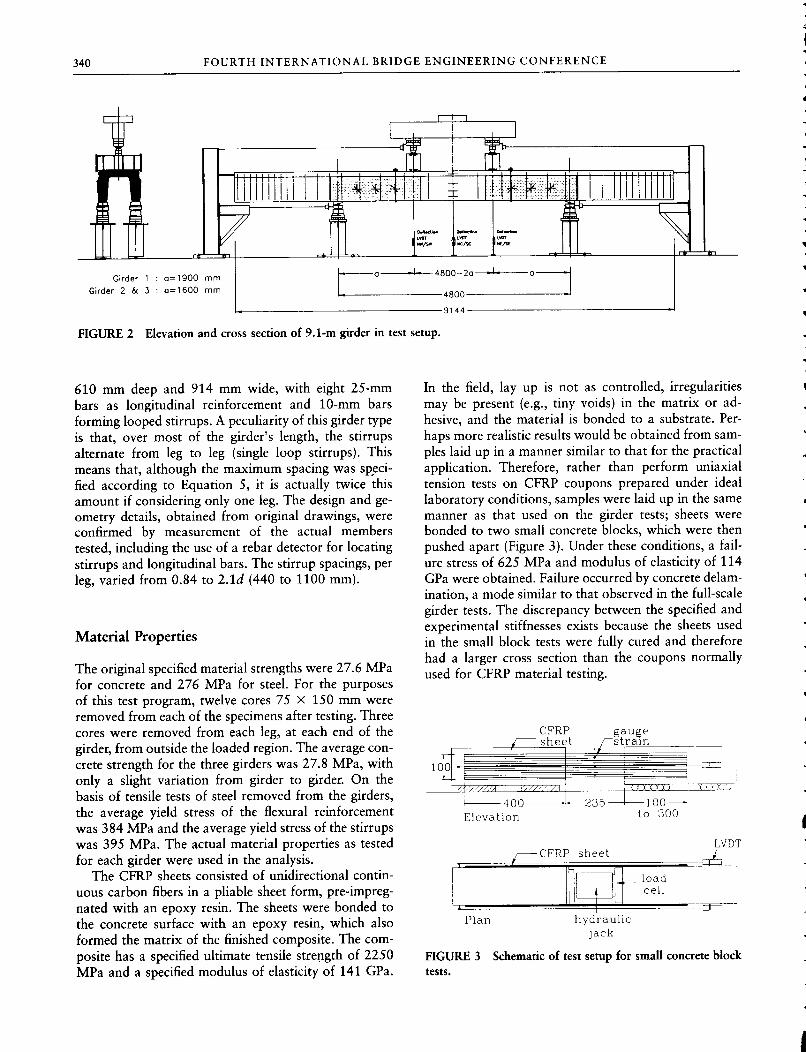
In the field, lay up is not as controlled, irregularities may be present (e.g., tiny voids) in the matrix or adhesive, and the material is bonded to a substrate. Perhaps more reahstic results would be obtained f rom samples laid up in a manner similar to that for the practical application. Therefore, rather than perform uniaxial tension tests on CFRP coupons prepared under ideal laboratory conditions, samples were laid up in the same manner as that used on the girder tests; sheets were bonded to two small concrete blocks, which were then pushed apart (Figure 3). Under these conditions, a failure stress of 625 MPa and modulus of elasticity of 114 GPa were obtained. Failure occurred by concrete delam-ination, a mode similar to that observed in the full-scale girder tests. The discrepancy between the specified and experimental stiffnesses exists because the sheets used in the small block tests were fully cured and therefore had a larger cross section than the coupons normally used for CFRP material testing.
CFRP " sheet
gauge strain
f Y Y •< y X ) , X T - O
Elevation 00 —
to 300
-CFRP sheet LVDT
load cell
Plan hydraulic jack
FIGURE 3 Schematic of test setup for small concrete block tests.

DRIMOUSSIS AND C H E N G 341
CFRP Strengthening Schemes
For the strengthening technique to be a practical solution for use on this type of bridge, the limited access in the field (i.e., only f rom beneath the structure) had to be taken into consideration. When the girders are in place in a bridge, the outer faces of the webs are almost flush against each other, wi th only a small gap between adjacent legs. Therefore, access is available only to the inside web faces and bottom flanges of the girders. The depth of the girder over which sheets can be applied is thus also limited. As much as possible, the vertical bonded length was varied f rom specimen to specimen.
The sheets were applied continuously throughout the shear span (shaded regions in Figure 2); the variations for each girder are summarized in Figure 4. Either one or two layers of CFRP were bonded to the webs. One layer was always oriented vertically. The second, if used, was oriented horizontally. The east shear span of Girder 1 was left unstrengthened to serve as a control. In the west span, two layers of CFRP sheets were used—the bottom layer oriented vertically and the top one horizontally. The vertical sheets extended between the top and bottom chamfers, 430 mm in length. The horizontal sheet was centered vertically on the inside face of the web leg and was the width of the sheet (300 mm). This strengthening arrangement was repeated on
the east shear span of Girder 2 as the first girder failed prematurely in flexure before failing the west span in shear. The west shear span of Girder 2 was strengthened with one vertical layer only. In this case, the sheet was extended slightly higher, along the chamfer to meet the underside of the top flange. Because the west span of Girder 1 failed prematurely in flexure before failing in shear, three longitudinal layers of CFRP sheets were applied, in addition to shear strengthening, to the bottom flange of Girders 2 and 3 to avoid flexural failure.
In the east span of Girder 3, the two-layer scheme of the west span of Girder 2 was again used, wi th the difference that the vertical sheet was extended, to wrap right around the bottom of the girder and, at the top, 30 mm onto the underside of the top flange. The west span was strengthened with one vertical layer, which not only wrapped around the bottom of the girder but continued up the outer face of the web leg, as high as possible, given that the concrete was sometimes chipped away where the group key had been. This last method was not practicable as a field application but gave an indication of the improvement that was possible if the member could be strengthened on both sides of both legs—perhaps more feasible on other types of girder cross sections. Note, however, that the bonded length was even shorter on the outer face, and this may affect results more than the advantage gained.
Girder 1
West span
Girder 2 West span
Girder 3 West span
Girder 1
East span
Girder 2 East span
Girder 3 East span
FIGURE 4 Cross sections showing CFRP strengthening schemes.
Testing
The general test setup is shown in Figure 1. A l l girders were tested in symmetric four-point bending over a 4.8-m simple span. The objective was to achieve as high a V / M ratio as possible to avoid failing prematurely in flexure. The shear span/depth (a/d) ratio was thus minimized as much as possible while remaining in the beam behavior range and avoiding arching action. Preliminary analysis indicated that a/d = 3.6 would be appropriate. This ratio was further decreased for Girders 2 and 3 after Test 2 of Girder 1 ended with a flexural failure. Shear spans were 1.9,1.6, and 1.6 m for Girders 1, 2 and 3, respectively.
For two reasons the supports were located as far f rom the ends of the girder as possible without cracking the top concrete. First, they were located beyond all bar cutoff locations to avoid the complication of bar termination and anchorage problems, and to have consistent moment capacity throughout the tested region. Second, this permitted testing in the region of the girder wi th fewest stirrups, allowing the potential for most improvement wi th the strengthening method. I t is acknowledged that this is obviously not realistic given that these girders are actually simply supported at the ends, but the primary objective was to test for an in-
342 F O U R T H I N T E R N A T I O N A L B R I D G E E N G I N E E R I N G C O N F E R E N C E
crease in shear capacity under the worst-case situation. The load applied by the testing machine was distributed to loading pads centered over the legs—a total of four load points. The girder was supported under each leg; that is, a total of four supports, each of which was monitored by a load cell. Thus, each leg was simply supported and, taking into account the various stirrup arrangements and the locally measured reactions, four shear spans could be analyzed independently.
Vertical deflections were measured wi th 25-mm linear variable differential transformers (LVDTs) located under both legs, at each of the load points and at mid-span. Strains on the concrete surface on the outer faces of the girder were measured using a 200-mm Demec gauge. Electrical resistance strain gauges wi th a gauge length of 5 mm were used extensively to obtain a distribution of strains over the strengthened shear span. In both shear spans, 2.5-mm LVDTs mounted between the top and bottom flanges at the location of stirrups measured the overall depth change of the girder as an indirect measure of vertical strain. These measurements, along with the visual aid of surface crack patterns, helped indicate i f or when the stirrups were yielding. Because each girder was tested more than once, the first tests were continued only until the load leveled off. The tests were then stopped, and the specimen was unloaded completely. To test both shear spans of each girder, assuming that one side would fai l first by a significant margin, some means of repairing the failed span was required. This was achieved by using external stirrups consisting of four threaded tie rods 25 mm in diameter at six locations along the shear span. After the shear span failed, the test was stopped and the specimen was completely unloaded. Holes were drilled through the top flange between the web legs, and rods were in
stalled, braced wi th two HSS members (75 X 100 mm) above and below the member.
TEST RESULTS
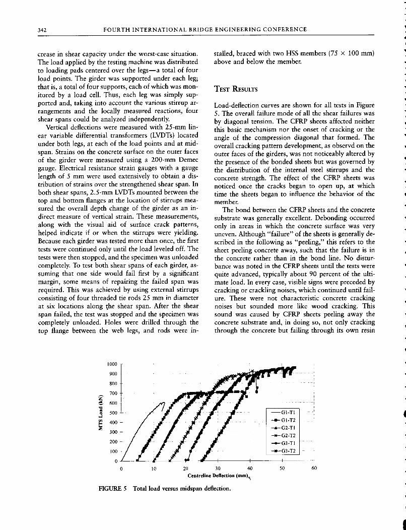
Load-deflection curves are shown for all tests in Figure 5. The overall failure mode of all the shear failures was by diagonal tension. The CFRP sheets affected neither this basic mechanism nor the onset of cracking or the angle of the compression diagonal that formed. The overall cracking pattern development, as observd on the outer faces of the girders, was not noticeably altered by the presence of the bonded sheets but was governed by the distribution of the internal steel stirrups and the concrete strength. The effect of the CFRP sheets was noticed once the cracks began to open up, at which time the sheets began to influence the behavior of the member.
The bond between the CFRP sheets and the concrete substrate was generally excellent. Debonding occurred only in areas in which the concrete surface was very uneven. Although "failure" of the sheets is generally described in the following as "peeling," this refers to the sheet peeling concrete away, such that the failure is in the concrete rather than in the bond line. No disturbance was noted in the CFRP sheets until the tests were quite advanced, typically about 90 percent of the ult imate load. In every case, visible signs were preceded by cracking or crackling noises, which continued until failure. These were not characteristic concrete cracking noises but sounded more Uke wood cracking. This sound was caused by CFRP sheets peeling away the concrete substrate and, in doing so, not only cracking through the concrete but failing through its own resin
1000 -T
500 +
10 20 30 40
Centreline Deflection (mm)^ 50
FIGURE 5 Total load versus midspan deflection.

DRIMOUSSIS AND C H E N G 343
(a)
Elevation - interior face face of web leg
peeling sheets
Cross-sect ion
(b)
CFRP sheets
FIGURE 6 Progression of failure of cracked section with bonded CFRP sheets.
deformed shape
matrix once peeled away f rom the main body. In no cases did the fibers fail in tension. Although they broke in some instances, this was caused by local stress concentrations. The horizontal sheets did not seem to have a significant influence on the behavior of the member; no difference was seen in the load capacity achieved.
Peeling always began near the top or bottom edges of the sheets, but the severity and progression of failure depended a great deal on the detailing and bonded lengths provided. Figure 6 shows failure cracks spanned by the CFRP sheets. The vertical hatching indicates fibers and concrete still intact. The diagonal hatching indicates where the sheets have peeled away the concrete. If the anchorage provided was not adequate, failure progressed as shown in Figure 6a; the first signs of distress were at the top or bottom edges of the sheets. To extend the sheets up the top chamfer, they had to be bent around a relatively abrupt corner, which made it difficult to get as good a bond to the concrete in the corner. Under increasing load, tension in the sheet straightened the bend and the sheet began to "pop o f f " along this corner, although it remained well bonded above along the chamfer itself and below along the height of the web. This was typical of the first sign of distress seen in cases where the sheet was continued up around this corner of the girder. Once the sheets began peeling away the concrete at the top and bottom (Points A and B), failure continued progressively toward the crack line. The peeling began once the bonded length
L I or L2 or both, became small enough. During the observed tests, this occurred when L I or L2 approached about 75 mm. The situation shown schematically in Figure 6a was exhibited by Girders 1 and 2. This can also be seen in Figure 7; delamination of sheet and concrete has occurred f rom both the top and bottom edges. In Figures 7 and 8, the white lines drawn on the CFRP surface indicate the extent of peeling or bulging.
If the anchorage is good enough at top and bottom, then the progression of failure wi l l be more like that in
intact
bottom of web leg
FIGURE 7 Interior face of one web leg, after failure (Girder 2, Test 1). ^ ,

344 FOURTH INTERNATIONAL BRIDGE ENGINEERING CONFERENCE
Figure 6b; the sheets were not peeling away the concrete layer but were bulging away f rom the substrate. As long as the sheets remain anchored, the tensile strength of the sheet can be developed, despite the bulging, and they can continue to carry load. The details used in the shear spans of Girder 3 resulted in this improved behavior, as can also be seen in Figure 8. Although this bulging continued up to the top flange, almost everywhere the CFRP remained attached to the concrete along the chamfer, and thus the tension in the sheets could continue to be mobilized over the fu l l height of the sheets, unlike the places where the sheets pulled away completely f rom the bottom flange up. In both spans of Girder 3, the sheets wrapped around the bottom flange, and this kind of bottom-edge peeling did not occur.
DISCUSSION OF TEST RESULTS '
Because each of the girder legs was loaded and supported concentrically, the shear capacity of the section was determined per leg using the load measured by the load cell at the support and based on a cross section consisting of one leg only.
! total shear capacity is given by The
V „ = V , + V . + VcFRP (8)
where V „ V, and VCHRP are the shear resistances provided by the concrete, stirrups, and CFRP sheets, respectively.
To account for the force carried by the stirrups, each leg in each span was considered individually. Observations of the crack patterns and measurement of vertical member deformations indicated if a stirrup was mobilized. Because there were only ever one or two stirrups
underside of top flange
IHHI chamfer
peeluig/bulgmg away
intact
bottom of web leg
FIGURE 8 Interior face of one web leg, after failure (Girder 3, Test 1).
per shear span, in almost aU cases it was clear f rom crack pattern observations and measured vertical strains which stirrups were yielding. In two cases, observations and measured strains did not warrant neglecting the stirrup completely but did not support yielding either. Therefore, an estimate was made of the force in the stirrup, equivalent to half a stirrup. The stirrup contribution was then calculated as
A^fy (9)
The control section consisted of the northeast and southeast legs of Girder 1. Both these regions had one stirrup yielding, and this information was used wi th Equation 9 to calculate, the V, contribution. Because no CFRP sheets were used in the east span. Equation 8 could be reduced and rearranged as
= V „
where V„TEST is the average of the two load cell readings at the northeast and southeast reactions, including the shear caused by the girder's own weight.
Table 1 summarizes the shear capacity results for each leg of the shear span. V„TEST comes directly f rom the test results and is the maximum shear carried by that leg at failure as measured by the reaction load ceU, including the girder's own weight. The concrete contribution was calculated using the actual material properties and the Zsutty formulation (3):
V, = 2.137 (npJ/aY (10)
The shear capacity attributed to the sheets was calculated as:
VCHRP = V„-
Table 1 shows the calculated values for V„ V^, and VcFRp The shear carried by each specimen, V„TEST, was compared with the shear carried by the control section, VGITI (subscript G l T l denotes Girder 1, Test 1) to determine the increase in shear strength made possible by the use of the bonded CFRP sheets. Because the control section included only one internal steel stirrup per leg, a direct comparison could be made only to other sections with only one stirrup per leg. I f the test section had a fewer or greater number of stirrups, the comparison was made possible by adjusting VGITI appropriately. Hence, for example, for the southeast leg of G2-T l , the ratio V„TESI^VGITI was calculated as the following:
V „ „ s T 192 k N
V c . t T , -V ,
169 k N -53.5 k N

DRIMOUSSIS AND C H E N G 345
TABLE 1 Shear Capacity Results of Girder Tests
No. of
Failure Critical Stirrups VnTEST Vc V , VcFRP VcFRP VnTEST
Mode leg Crossed (kN) (kN) (kN) (kN) VnTEST VGITI
Girder 1
Test 1 diagonal South East" 1 168 115.7 53,8 - - -(Control) shear North East" 1 171 115.7 53.8 - - -Test 2 flexure South West 0,5 184 115.7 26,9 41 ,4 0 ,23 1,29
North West 1 2 0 5 115.7 53,8 35,5 0 , 1 7 1,21
Girder 2 Test 1 diagonal South East 0.5 192 126.9 26 ,75 38 .35 0 , 2 0 1.35
shear North East" 0.5 198 126.9 26 ,75 4 4 . 3 5 0 ,22 1.39
Test 2 diagonal South West" 1 2 2 9 126.9 53.5 48 .6 0 , 2 1 1.35
shear North West" 1.5 263 126.9 80.3 55 .8 0 , 2 1 1.34
Girder 3 Test 1 diagonal South East 1 2 3 7 128.1 54.8 5 4 . 1 0 ,23 1.40
shear North East- 1 235 128.1 54.8 52 .1 0 ,22 1.39
Test 2 diagonal South West" 1 2 3 9 128.1 54.8 5 6 . 1 0 ,23 1.41
shear North West" 1 263 128.1 54.8 80 .1 0 ,30 1.55
° Critical leg(s)
As seen in the Table 1, the CFRP-strengthened sections showed an improvement of 2 1 to 5 5 percent over G l - T l . Included in Table 1 is the ratio VCFRP/V„TEST, which indicates the proportion of the shear capacity of the section attributed to the bonded CFRP sheets. This ratio ranged between 0 . 1 7 and 0 .30 . The degree to which the composite sheets improved the shear capacity did not seem to clearly depend on particular parameters. This was most likely because of the interaction of various conditions, such as strength of concrete, effectiveness of the internal stirrups, and effectiveness of the bonded sheets.
It is proposed that the CFRP sheets bonded to the webs of the members contribute to the shear strength of the section by the interaction of two separate mechanisms. The first mechanism is one of crack control, in which the sheets act as "bandages" to prevent or l imit cracking. In the second mechanism, the fibers may be modeled as a series of "stirrups" and then analyzed in a manner analogous to that used for the analysis of sections reinforced wi th internal steel stirrups. Both of these two mechanisms w i l l be discussed and predictions of CFRP contribution to shear strength wi l l be calculated on the basis of the second model.
In the first mechanism, CFRP sheets can be effective in providing crack control when glued to the surface of concrete members. Fibers oriented in any direction can
contribute to this mechanism, although they w i l l be most efficient when oriented perpendicular to the crack line. I f cracks are pre-existing, CFRP sheets may easily be applied in the optimum orientation for repair purposes and would be even more effective if the member is first jacked so as to close the cracks before the sheets are applied. By holding the cracked surfaces together, the CFRP sheets can help increase the effective shear strength contribution of the concrete by maintaining or improving interface shear transfer. This effect may significantly improve the shear strength of the section.
In the second mechanism, the CFRP sheets are modeled as a series of discrete stirrups. I f the validity of this assumption is accepted, then the contribution of the sheets may be determined by existing methods of analysis used for steel stirrups, such as the truss model analogy. As is the case for internal steel stirrups, the CFRP sheets may be oriented either vertically or inclined to the vertical. For simplicity of design, to deal wi th stress reversals, and to avoid errors in construction, vertically oriented stirrups are preferable. During testing, the vertical fibers spanned over bulging sections, as long as anchorage at the top and bottom was sufficient, and so continued to carry load over their length for as long as they remained in this condition.
The familiar truss equation for shear was modified so that it could be applied to the use of bonded external
346 F O U R T H I N T E R N A T I O N A L B R I D G E E N G I N E E R I N G C O N F E R E N C E
sheets and includes several redefined terms:
(11)
where
cFRP = the cross-sectional area of one stirrup; s = the spacing of the stirrups;
Igff - the effective length of the sheets; and (T^ff = the design stress level used.
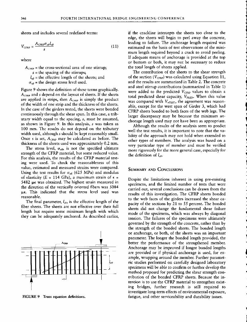
Figure 9 shows the definition of these terms graphically. AcFRp and s depend on the layout of sheets. I f the sheets are applied in strips, then ACFRP is simply the product of the width of one strip and the thickness of the sheets. In the case of the girders tested, the sheets were bonded continuously through the shear span. In this case, a tributary width equal to the spacing, s, must be assumed, as shown in Figure 9. In this analysis, s was taken as 100 mm. The results do not depend on the tributary width used, although s should be kept reasonably small. Once s is set, ACFRP may be calculated as before. The thickness of the sheets used was approximately 0.2 mm.
The stress level, a^u, is not the specified ultimate strength of the CFRP material, but some reduced value. For this analysis, the results of the CFRP material testing were used. To check the reasonableness of this value, estimated and measured strains were compared. Using the test results for a^f, (625 MPa) and modulus of elasticity (E - 114 GPa), a maximum strain of e = 5482 |JL6 was obtained. The highest strain measured in the direction of the vertically oriented fibers was 5084 |j,e. This indicated that the stress level used was reasonable.
The final parameter, l^a, is the effective length of the fiber sheets. The sheets are not effective over their fu l l length but require some minimum length wi th which they can be adequately anchored. As described earlier.
FIGURE 9 Truss equation definitions.
if the crackline intercepts the sheets too close to the edge, the sheets wi l l begin to peel away the concrete, leading to failure. The anchorage length required was estimated on the basis of test observations of the minimum length required beyond a crack to avoid peeling. If adequate means of anchorage is provided at the top or bottom or both, it may not be necessary to reduce the total length of sheets applied.
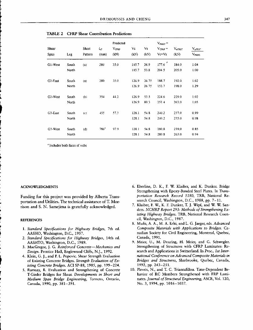
The contribution of the sheets to the shear strength of the section (VCFRP) was calculated using Equation 11, and the results are summarized in Table 2. The concrete and steel stirrup contributions (summarized in Table 1) were added to the predicted VCFRP values to obtain a total predicted shear capacity, VPRED- When this value was compared wi th V„TEST) the agreement was reasonable, except for the west span of Girder 3, which had CFRP sheets bonded to both faces of the web legs. The larger discrepancy may be because the minimum anchorage length used may not have been as appropriate.
Although the results of the analysis seem to predict well the test results, i t is important to note that the validity of the approach may not hold when extended to other types of members. The analysis was based on a very particular type of member and must be verified more rigorously for the more general case, especially for the definition of l^n.
SUMMARY AND CONCLUSIONS
Despite the limitations inherent in using pre-existing specimens, and the limited number of tests that were carried out, several conclusions can be drawn f rom the results of this investigation. The CFRP sheets bonded to the web faces of the girders increased the shear capacity of the sections by 21 to 55 percent. The bonded sheets did not change the fundamental shear failure mode of the specimens, which was always by diagonal tension. The failures of the specimens were ultimately governed by the strength of the concrete, rather than by the strength of the bonded sheets. The bonded length or anchorage, or both, of the sheets was an important parameter. The longer the bonded length provided, the better the performance of the strengthened member. Anchorage may be improved if longer bonded lengths are provided or i f physical anchorage is used, for example, wrapping around the member. Further parametric studies performed on carefully designed laboratory specimens wi l l be able to confirm or further develop the method proposed for predicting the shear strength contribution of the bonded CFRP sheets. Because the intention is to use the CFRP material to strengthen existing bridges, further research is still required to investigate long-term effects of environmental exposure, fatigue, and other serviceability and durability issues.
DRIMOUSSIS AND C H E N G 347
TABLE 2 CFRP Shear Contribution Predictions
Predicted VpRED -
Shear Sheet VcFRP Vc Vs VcFRP + VnTEST VnTEST
Span Leg Pattern (nun) (kN) (kN) (kN) Vc+Vs (kN) VpRED
01-West South (a) 280 35.0 115.7 26.9 177.6 ' 184.0 1.04
North 115.7 53.8 204.5 205.0 1.00
G2-East South (a) 280 35.0 126.9 26.75 188.7 192.0 1.02
North 126.9 26.75 153.7 198.0 1.29
G2-West South (b) 354 44.2 126.9 53.5 224.6 229 0 1.02
North 126.9 80.3 251.4 263.0 1.05
03-East South (c) 455 57.3 128.1 54.8 240.2 237.0 0.99
North 128.1 54.8 240.2 235.0 0.98
03-West South (d) 786° 97.9 128.1 54.8 280.8 239.0 0.85
North 128.1 54.8 280.8 263.0 0.94
° Includes both faces of webs
ACKNOWLEDGMENTS
Funding for this project was provided by Alberta Transportation and Utilities. The technical assistance of T. Morrison and S. N . Samejima is gratefully acknowledged.
REFERENCES
1. Standard Specifications for Highway Bridges, 7th ed. AASHO, Washington, D.C., 1957.
2. Standard Specifications for Highway Bridges, 14th ed. AASHTO, Washington, D.C., 1989.
3. MacGregor, J. G. Reinforced Concrete—Mechanics and Design. Prentice Hall, Englewood Cliffs, N.J., 1992.
4. Klein, G. J., and P. L. Popovic. Shear Strength Evaluation of Existing Concrete Bridges. Strength Evaluation of Existing Concrete Bridges. ACI SP-88, 1985, pp. 199-224.
5. Ramsay, B. Evaluation and Strengthening of Concrete T-Girder Bridges for Shear. Developments in Short and Medium Span Bridge Engineering, Tornoto, Ontario, Canada, 1990, pp. 381-391.
6. Eberline, D. K., R W. Klaiber, and K. Dunker. Bridge Strengthening with Epoxy-Bonded Steel Plates. In Transportation Research Record 1180, TRB, National Research Council, Washington, D.C., 1988, pp. 7-11.
7. Klaiber, E W, K. E Dunker, T. J. Wipf, and W. W. Sanders. NCHRP Report 293: Methods of Strengthening Existing Highway Bridges. TRB, National Research Council, Washington, D.C., 1987.
8. Mufti , A. A., M . A. Erki, and L. G. Jaeger, eds. Advanced Composite Materials with Applications to Bridges. Canadian Society for Civil Engineering, Montreal, Quebec, Canada, 1991.
9. Meier, U., M . Deuring, H. Meier, and G. Schwegler. Strengthening of Structures with CFRP Laminates: Research and Applications in Switzerland. In Proc, 1st International Conference on Advanced Composite Materials in Bridges and Structures, Sherbrooke, Quebec, Canada, 1992, pp. 243-251.
10. Plevris, N . , and T. C. TriantafiUou. Time-Dependent Behavior of RC Members Strengthened with FRP Laminates. Journal of Structural Engineering, ASCE, Vol. 120, No. 3, 1994, pp. 1016-1037.