Embed Size (px)
Citation preview
1
Shelby GT500 Front Fascia Conversion Kit (05-09 All)
Item #53611
Installation Time: 1 Day
Required tools:
Phillips Screw driver
10mm Socket + Ratchet/Wrench
8mm Socket + Ratchet/Wrench
5mm Socket + Ratchet/Wrench
Automotive panel clip removal tool
Small Flat blade screw driver
Pop Rivet tool
Wire Stripper
Wire terminal crimp tool
Included Parts:
Front Bumper Cover Assembly Upper Grille Lower Grille Left Headlamp (Non-HID) Right Headlamp (Non-HID) Foglamps Foglight Wiring Connector with Pigtails Lower Valance Lower Valance Panel Bolts and Nuts Front Foam Impact Absorber Left Fender Liner Right Fender Liner Radiator Upper Shield Radiator Grille Right Mount Bracket Radiator Grille Left Mount Bracket Right Turnsignal Support Bracket Left Turnsignal Support Bracket Splash Shield Nuts Required Screws and Rivets
Removal of the Fascia
The front fascia being removed in the following pictures are off a 2007 GT.
2
Any of the fastening hardware, body clips etc… that are removed during the removal process, retain for
reassembly.
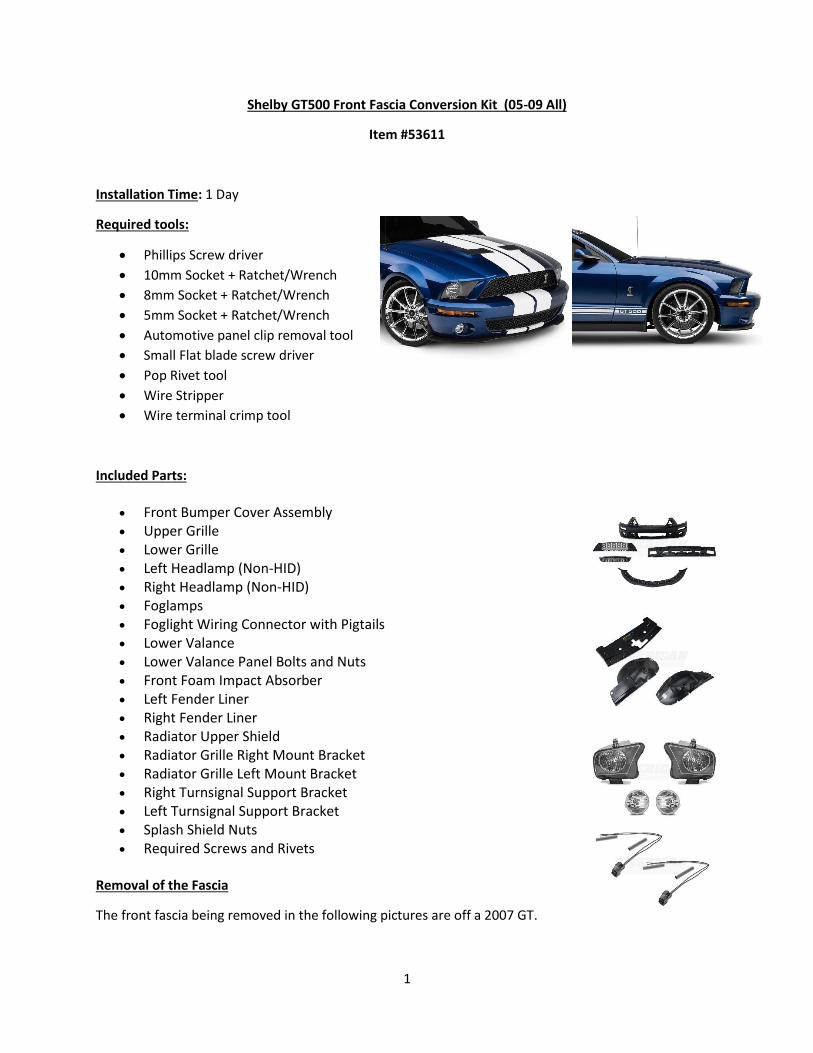
1. Remove Fuse number 17 from the fuse panel inside the car behind the removable door on the
passenger side kick panel. You can also remove the negative battery cable, however I choose to
retain the ECM adaptive strategy memory, GPS, and radio presets. This fuse may be a different
fuse for different models and model years. This is for the air bags. Check your owner’s manual
for proper identification.
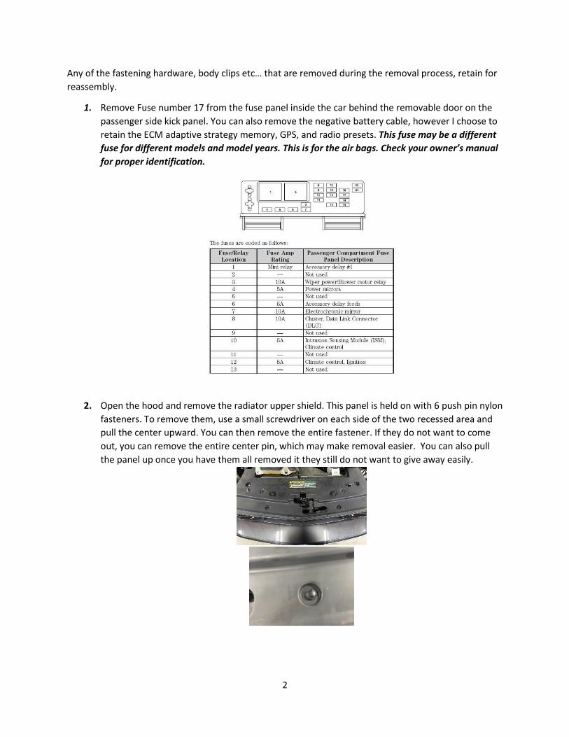
2. Open the hood and remove the radiator upper shield. This panel is held on with 6 push pin nylon
fasteners. To remove them, use a small screwdriver on each side of the two recessed area and
pull the center upward. You can then remove the entire fastener. If they do not want to come
out, you can remove the entire center pin, which may make removal easier. You can also pull
the panel up once you have them all removed it they still do not want to give away easily.
3
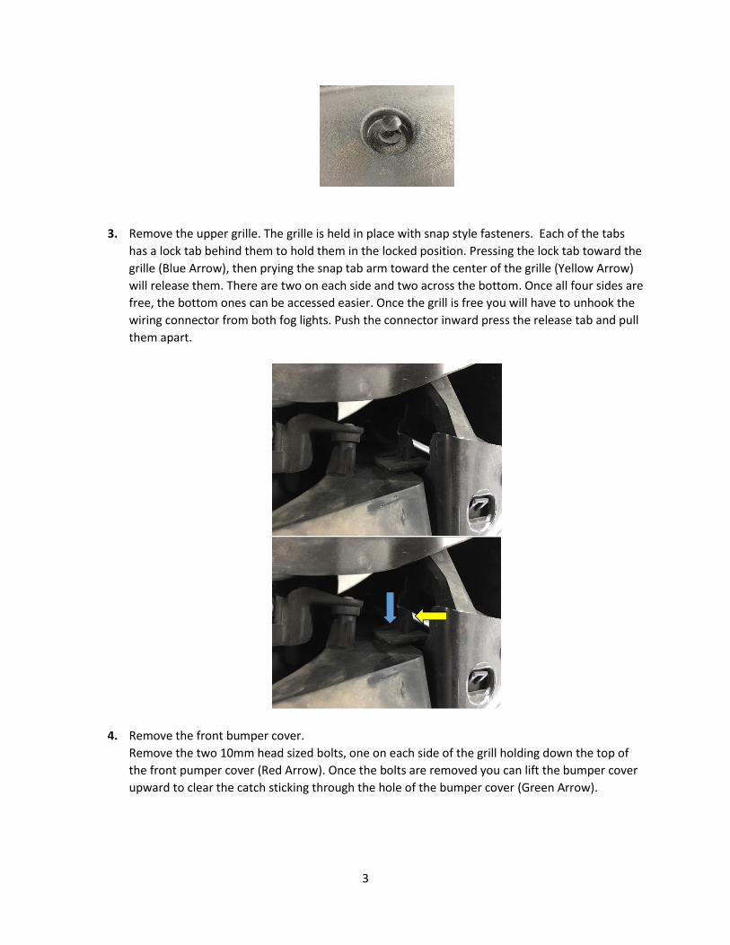
3. Remove the upper grille. The grille is held in place with snap style fasteners. Each of the tabs
has a lock tab behind them to hold them in the locked position. Pressing the lock tab toward the
grille (Blue Arrow), then prying the snap tab arm toward the center of the grille (Yellow Arrow)
will release them. There are two on each side and two across the bottom. Once all four sides are
free, the bottom ones can be accessed easier. Once the grill is free you will have to unhook the
wiring connector from both fog lights. Push the connector inward press the release tab and pull
them apart.
4. Remove the front bumper cover.
Remove the two 10mm head sized bolts, one on each side of the grill holding down the top of
the front pumper cover (Red Arrow). Once the bolts are removed you can lift the bumper cover
upward to clear the catch sticking through the hole of the bumper cover (Green Arrow).
4
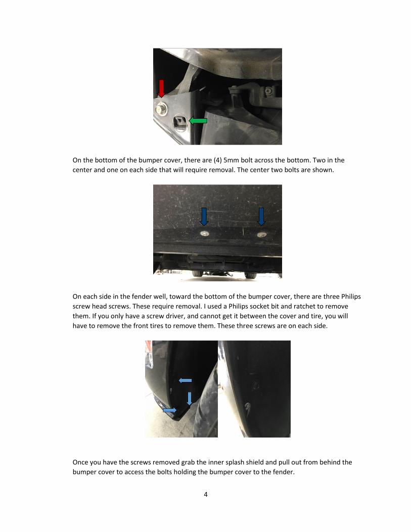
On the bottom of the bumper cover, there are (4) 5mm bolt across the bottom. Two in the
center and one on each side that will require removal. The center two bolts are shown.
On each side in the fender well, toward the bottom of the bumper cover, there are three Philips
screw head screws. These require removal. I used a Philips socket bit and ratchet to remove
them. If you only have a screw driver, and cannot get it between the cover and tire, you will
have to remove the front tires to remove them. These three screws are on each side.
Once you have the screws removed grab the inner splash shield and pull out from behind the
bumper cover to access the bolts holding the bumper cover to the fender.
5
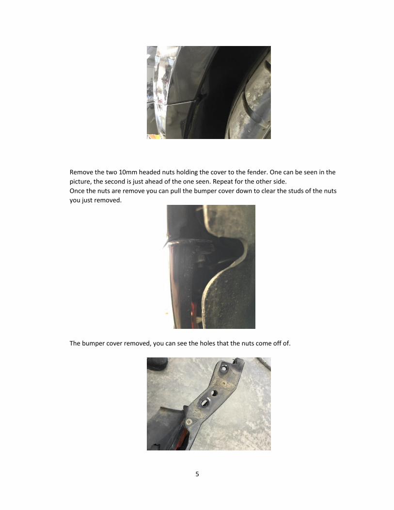
Remove the two 10mm headed nuts holding the cover to the fender. One can be seen in the
picture, the second is just ahead of the one seen. Repeat for the other side.
Once the nuts are remove you can pull the bumper cover down to clear the studs of the nuts
you just removed.
The bumper cover removed, you can see the holes that the nuts come off of.
6
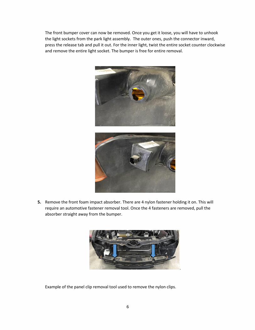
The front bumper cover can now be removed. Once you get it loose, you will have to unhook
the light sockets from the park light assembly. The outer ones, push the connector inward,
press the release tab and pull it out. For the inner light, twist the entire socket counter clockwise
and remove the entire light socket. The bumper is free for entire removal.
5. Remove the front foam impact absorber. There are 4 nylon fastener holding it on. This will
require an automotive fastener removal tool. Once the 4 fasteners are removed, pull the
absorber straight away from the bumper.
.
Example of the panel clip removal tool used to remove the nylon clips.
7
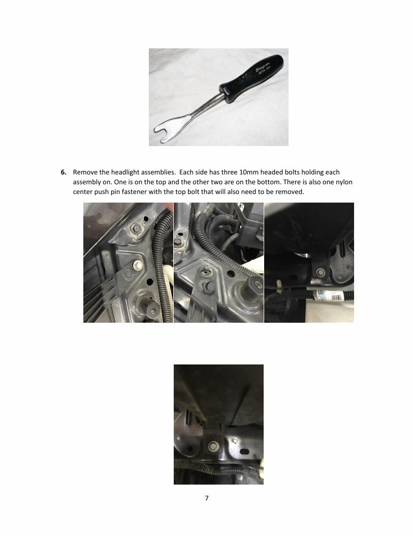
6. Remove the headlight assemblies. Each side has three 10mm headed bolts holding each
assembly on. One is on the top and the other two are on the bottom. There is also one nylon
center push pin fastener with the top bolt that will also need to be removed.
8
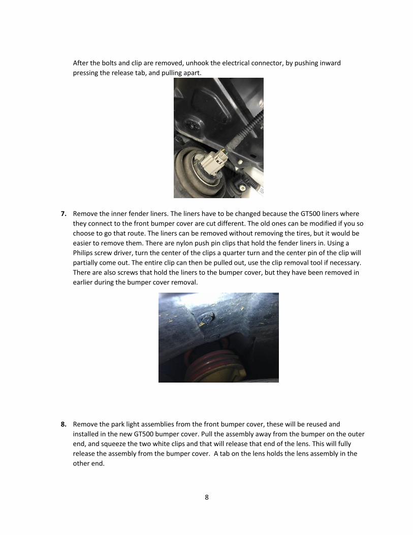
After the bolts and clip are removed, unhook the electrical connector, by pushing inward
pressing the release tab, and pulling apart.
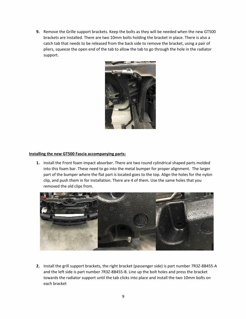
7. Remove the inner fender liners. The liners have to be changed because the GT500 liners where
they connect to the front bumper cover are cut different. The old ones can be modified if you so
choose to go that route. The liners can be removed without removing the tires, but it would be
easier to remove them. There are nylon push pin clips that hold the fender liners in. Using a
Philips screw driver, turn the center of the clips a quarter turn and the center pin of the clip will
partially come out. The entire clip can then be pulled out, use the clip removal tool if necessary.
There are also screws that hold the liners to the bumper cover, but they have been removed in
earlier during the bumper cover removal.
8. Remove the park light assemblies from the front bumper cover, these will be reused and
installed in the new GT500 bumper cover. Pull the assembly away from the bumper on the outer
end, and squeeze the two white clips and that will release that end of the lens. This will fully
release the assembly from the bumper cover. A tab on the lens holds the lens assembly in the
other end.
9
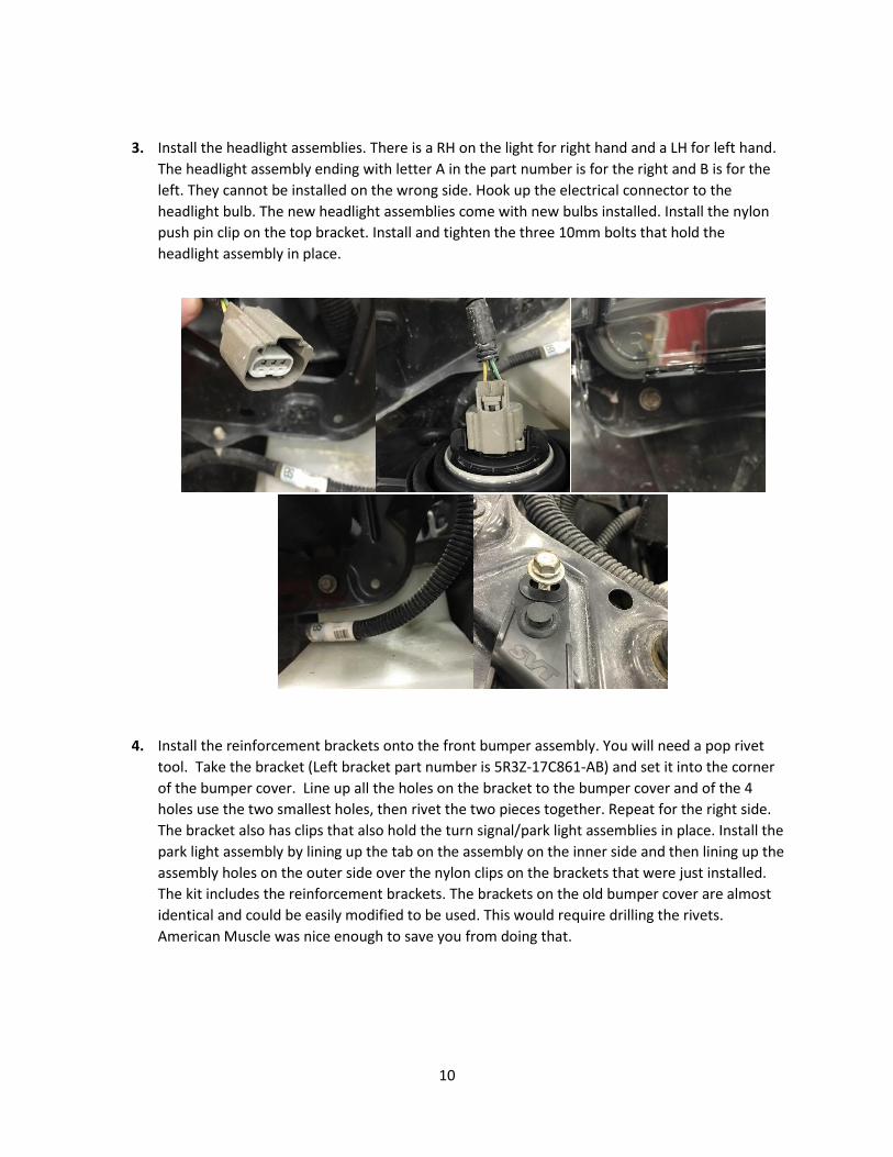
9. Remove the Grille support brackets. Keep the bolts as they will be needed when the new GT500
brackets are installed. There are two 10mm bolts holding the bracket in place. There is also a
catch tab that needs to be released from the back side to remove the bracket, using a pair of
pliers, squeeze the open end of the tab to allow the tab to go through the hole in the radiator
support.
Installing the new GT500 Fascia accompanying parts:
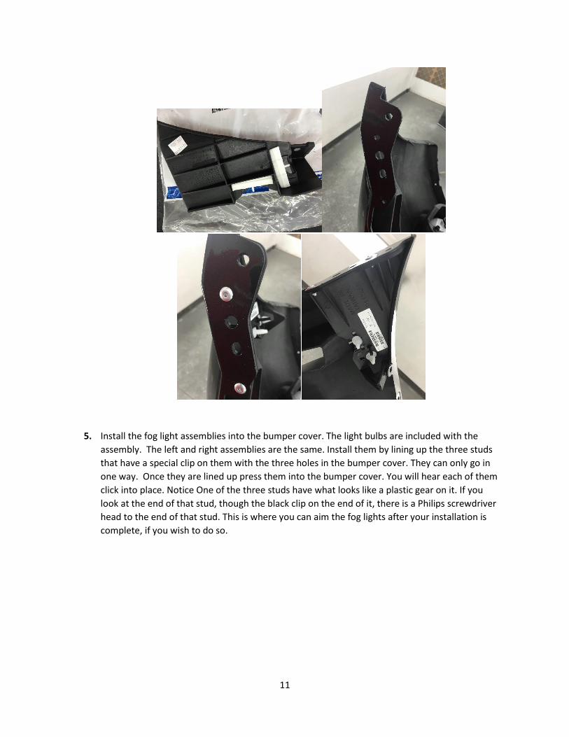
1. Install the Front foam impact absorber. There are two round cylindrical shaped parts molded
into this foam bar. These need to go into the metal bumper for proper alignment. The larger
part of the bumper where the flat part is located goes to the top. Align the holes for the nylon
clip, and push them in for installation. There are 4 of them. Use the same holes that you
removed the old clips from.
2. Install the grill support brackets, the right bracket (passenger side) is part number 7R3Z-8B455-A
and the left side is part number 7R3Z-8B455-B. Line up the bolt holes and press the bracket
towards the radiator support until the tab clicks into place and install the two 10mm bolts on
each bracket
10
3. Install the headlight assemblies. There is a RH on the light for right hand and a LH for left hand.
The headlight assembly ending with letter A in the part number is for the right and B is for the
left. They cannot be installed on the wrong side. Hook up the electrical connector to the
headlight bulb. The new headlight assemblies come with new bulbs installed. Install the nylon
push pin clip on the top bracket. Install and tighten the three 10mm bolts that hold the
headlight assembly in place.
4. Install the reinforcement brackets onto the front bumper assembly. You will need a pop rivet
tool. Take the bracket (Left bracket part number is 5R3Z-17C861-AB) and set it into the corner
of the bumper cover. Line up all the holes on the bracket to the bumper cover and of the 4
holes use the two smallest holes, then rivet the two pieces together. Repeat for the right side.
The bracket also has clips that also hold the turn signal/park light assemblies in place. Install the
park light assembly by lining up the tab on the assembly on the inner side and then lining up the
assembly holes on the outer side over the nylon clips on the brackets that were just installed.
The kit includes the reinforcement brackets. The brackets on the old bumper cover are almost
identical and could be easily modified to be used. This would require drilling the rivets.
American Muscle was nice enough to save you from doing that.
11
5. Install the fog light assemblies into the bumper cover. The light bulbs are included with the
assembly. The left and right assemblies are the same. Install them by lining up the three studs
that have a special clip on them with the three holes in the bumper cover. They can only go in
one way. Once they are lined up press them into the bumper cover. You will hear each of them
click into place. Notice One of the three studs have what looks like a plastic gear on it. If you
look at the end of that stud, though the black clip on the end of it, there is a Philips screwdriver
head to the end of that stud. This is where you can aim the fog lights after your installation is
complete, if you wish to do so.
12
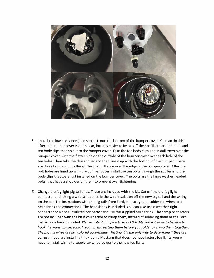
6. Install the lower valance (chin spoiler) onto the bottom of the bumper cover. You can do this
after the bumper cover is on the car, but It is easier to install off the car. There are ten bolts and
ten body clips that hold it to the bumper cover. Take the ten body clips and install them over the
bumper cover, with the flatter side on the outside of the bumper cover over each hole of the
ten holes. Then take the chin spoiler and then line it up with the bottom of the bumper. There
are three tabs built into the spoiler that will slide over the edge of the bumper cover. After the
bolt holes are lined up with the bumper cover install the ten bolts through the spoiler into the
body clips that were just installed on the bumper cover. The bolts are the large washer headed
bolts, that have a shoulder on them to prevent over tightening.
7. Change the fog light pig tail ends. These are included with the kit. Cut off the old fog light
connector end. Using a wire stripper strip the wire insulation off the new pig tail and the wiring
on the car. The instructions with the pig tails from Ford, instruct you to solder the wires, and
heat shrink the connections. The heat shrink is included. You can also use a weather tight
connector or a none insulated connector and use the supplied heat shrink. The crimp connectors
are not included with the kit if you decide to crimp them, instead of soldering them as the Ford
instructions have indicated. Please note if you plan to use LED lights you will have to be sure to
hook the wires up correctly. I recommend testing them before you solder or crimp them together.
The pig tail wires are not colored accordingly. Testing it is the only way to determine if they are
correct. If you are installing this kit on a Mustang that does not have factory fog lights, you will
have to install wiring to supply switched power to the new fog lights.
13
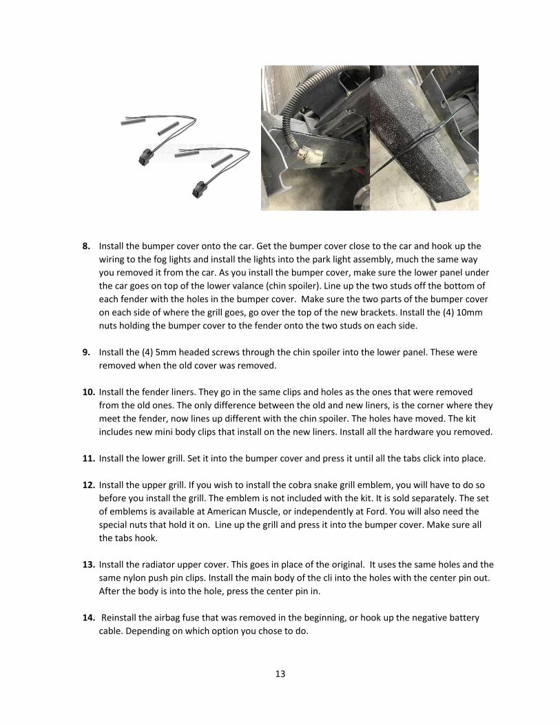
8. Install the bumper cover onto the car. Get the bumper cover close to the car and hook up the
wiring to the fog lights and install the lights into the park light assembly, much the same way
you removed it from the car. As you install the bumper cover, make sure the lower panel under
the car goes on top of the lower valance (chin spoiler). Line up the two studs off the bottom of
each fender with the holes in the bumper cover. Make sure the two parts of the bumper cover
on each side of where the grill goes, go over the top of the new brackets. Install the (4) 10mm
nuts holding the bumper cover to the fender onto the two studs on each side.
9. Install the (4) 5mm headed screws through the chin spoiler into the lower panel. These were
removed when the old cover was removed.
10. Install the fender liners. They go in the same clips and holes as the ones that were removed
from the old ones. The only difference between the old and new liners, is the corner where they
meet the fender, now lines up different with the chin spoiler. The holes have moved. The kit
includes new mini body clips that install on the new liners. Install all the hardware you removed.
11. Install the lower grill. Set it into the bumper cover and press it until all the tabs click into place.
12. Install the upper grill. If you wish to install the cobra snake grill emblem, you will have to do so
before you install the grill. The emblem is not included with the kit. It is sold separately. The set
of emblems is available at American Muscle, or independently at Ford. You will also need the
special nuts that hold it on. Line up the grill and press it into the bumper cover. Make sure all
the tabs hook.
13. Install the radiator upper cover. This goes in place of the original. It uses the same holes and the
same nylon push pin clips. Install the main body of the cli into the holes with the center pin out.
After the body is into the hole, press the center pin in.
14. Reinstall the airbag fuse that was removed in the beginning, or hook up the negative battery
cable. Depending on which option you chose to do.
14
15. Have the headlights and fog lights aligned. It would be recommended that you have them aimed
at a Ford Garage or auto body shop that has equipment to aim them properly.
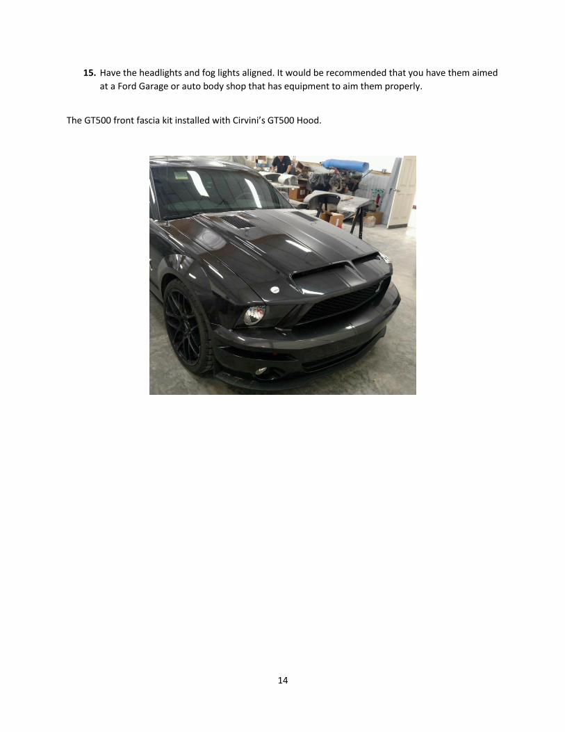
The GT500 front fascia kit installed with Cirvini’s GT500 Hood.