Embed Size (px)
Citation preview

COLUMBIA COUNTY BOARD OF COUNTY COMMISSIONERSBID NO. 2016-RADDENDUM 2.
Sheriff’s Office GEO study attached.
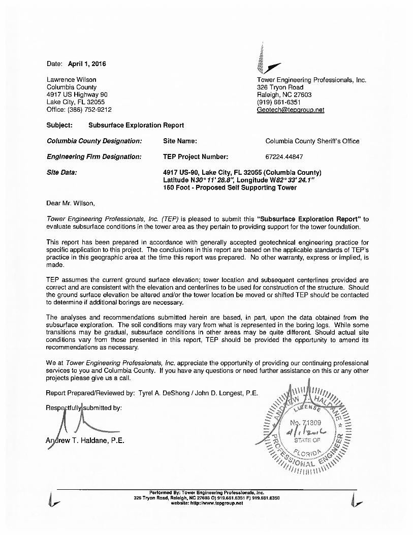
Date: April 1, 2016
Lawrence Wilson Tower Engineering Professionals, Inc.Columbia County 326 Tryon Road4917 US Highway 90 Raleigh, NC 27603Lake City, FL 32055 (919) 661-6351Office: (386) 752-9212 Geotechftepcjroup. net
Subject: Subsurface Exploration Report
Columbia County Designation: Site Name: Columbia County Sheriff’s Office
Engineering Firm Designation: TEP Project Number: 67224.44847
Site Data: 4917 US-90, Lake City, FL 32055 (Columbia County)Latitude N30° 71 ‘28.8’ Longitude W82° 33’24. 1”160 Foot - Proposed Self Supporting Tower
Dear Mr. Wilson,
Tower Engineering Professionals, Inc. (TEP) is pleased to submit this “Subsurface Exploration Report” toevaluate subsurface conditions in the tower area as they pertain to providing support for the tower foundation.
This report has been prepared in accordance with generally accepted geotechnical engineering practice forspecific application to this project. The conclusions in this report are based on the applicable standards of TEP’spractice in this geographic area at the time this report was prepared. No other warranty, express or implied, ismade.
TEP assumes the current ground surface elevation; tower location and subsequent centerlines provided arecorrect and are consistent with the elevation and centerlines to be used for construction of the structure. Shouldthe ground surface elevation be altered and/or the tower location be moved or shifted TEP should be contactedto determine if additional borings are necessary.
The analyses and recommendations submitted herein are based, in part, upon the data obtained from thesubsurface exploration. The soil conditions may vary from what is represented in the boring logs. While sometransitions may be gradual, subsurface conditions in other areas may be quite different. Should actual siteconditions vary from those presented in this report, TEP should be provided the opportunity to amend itsrecommendations as necessary.
We at Tower Engineering Professionals, Inc. appreciate the opportunity of providing our continuing professionalservices to you and Columbia County. If you have any questions or need further assistance on this or any otherprojects please give us a call.
Report Prepared/Reviewed by: Tyrel A. DeShong / John D. Longest, P.E.
Resectfuimfttedb:
A,ew I. Haldane, P.E.
Performed By: Tower Engineering Professionals, Inc.326 Tryon Road, Raleigh, NC 276030)919.661.6351 F) 919.661.6350
website: http://www.tepgroup.net
April 7, 2076760 Ft Self Supporting Subsurface Exploration Report Columbia County Sheriff’s OfficeProject Number 67224.44847 Page 2
TABLE OF CONTENTS
1) PROJECT DESCRIPTION
2) SITE EXPLORATION
3) SITE CONDITIONS
4) SUBSURFACE CONDITIONS4.1) Soil4.2) Rock4.3) Subsurface Water4.4) Frost
5) TOWER FOUNDATION DESIGN5.1) Shallow Foundation5.2) Drilled Shaft FoundationTable 1 - Drilled Shaft Foundation Analysis Parameters
6) SOIL RESISTIVITY
7) CONSTRUCTION CONSIDERATIONS - DRILLED SHAFTS
8) APPENDIX ABoring Layout
9) APPENDIX BBoring Log
Performed By: Tower Engineering Professionals, Inc.326 Tryon Road, Raleigh, NC 27603 0)919.661.6351 F) 919.661.6350
website: http://www.tepgroup.net
April 7, 2076760 Ft Self Supporting Subsurface Exploration Report Columbia County Sheriff’s OfficeProject Number 67224.44847 Page 3
1) PROJECT DESCRIPTION
Based on the preliminary drawings, it is understood a self supporting communications tower will be constructedat the referenced site. The structure loads will be provided by the tower manufacturer.
2) SITE EXPLORATION
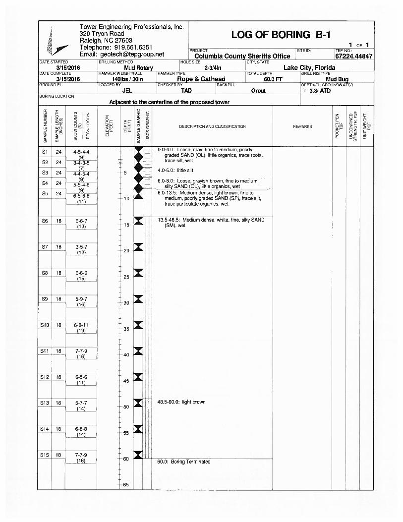
The field exploration included the performance of one soil test boring (B-i) to the planned depth of 60 feet (bgs)at the centerline of the proposed self supporting tower. The boring was performed by an ATV mounted drill rigusing mud rotary drilling techniques to advance the boring. Split-spoon samples and Standard PenetrationResistance Values (N-values) were obtained in accordance with ASTM D i 586 at a frequency of five samples inthe top i 0 feet and one sample every 5 feet thereafter.
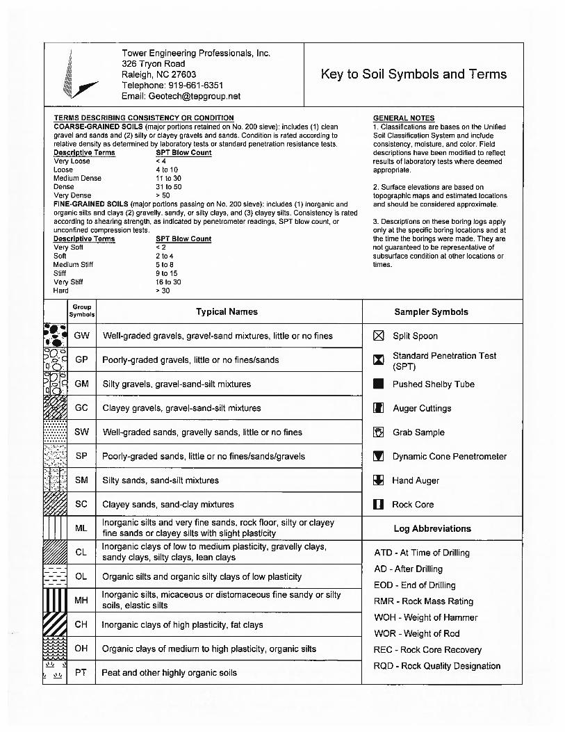
The Split-spoon samples were transported to the TEP laboratory where they were classified by a GeotechnicalEngineer in general accordance with the Unified Soil Classification System (USCS), using visual-manualidentification procedures (ASTM D 2488).
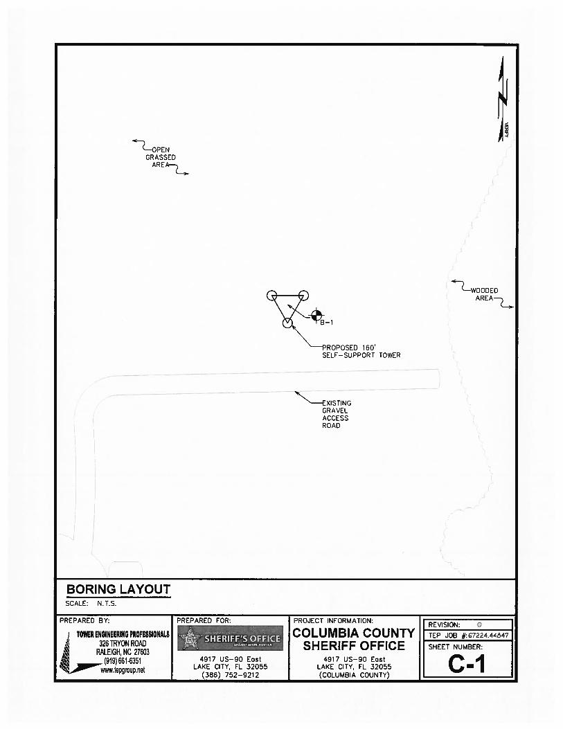
A Boring Location Plan showing the approximate boring location, a Boring Log presenting the subsurfaceinformation obtained and a brief guide to interpreting the boring log are included in the Appendix.
3) SITE CONDITIONS
The site is located at 4917 US-90 in Lake City, Columbia County, Florida. The proposed tower and compoundare to be located in an open grassy field. The ground topography is relatively level to lightly sloping.
4) SUBSURFACE CONDITIONS
The following description of subsurface conditions is brief and general. For more detailed information, theindividual Boring Log contained in Appendix B - Boring Log may be consulted.
4.1) Soil
The USCS classification of the materials encountered in the boring include OL, SP, and SM. TheStandard Penetration Resistance (N” Values) recorded in the materials ranged from 7 to 19 blowsper foot of penetration.
4.2) Rock
Rock was not encountered in the boring. Refusal of auger advancement was not encountered in theboring.
4.3) Subsurface Water
Subsurface water was encountered at a depth of 3.3 feet (bgs) in the boring at the time of drilling. Itshould be noted the subsurface water level will fluctuate during the year, due to seasonal variationsand construction activity in the area.
4.4) Frost
The TIA frost depth for Columbia County, Florida is 0 inches.
Performed By: Tower Engineering Professionals, Inc.326 Tryon Road, Raleigh, NC 276030) 919.661.6351 F) 919.667.6350
website: http:/iww.tepgroup.net
April 7, 2076760 Ft Self Supporting Subsurface Exploration Report Columbia County Sheriff’s OfficeProject Number 67224.4484 7 Page 4
5) TOWER FOUNDATION DESIGN
Based on the boring data, it is the opinion of TEP that single drilled shaft for each leg can be used to support thenew tower. If the drilled shaft foundation option is utilized, design of the foundation should be adjusted toterminate in a known material. The following presents TEP’s conclusions and recommendations regarding thefoundation type.
5.1) Shallow Foundation
Due to the organic materials encountered in the first 8 feet of the boring, a Shallow foundation is notrecommended for this site. See Section 5.2) for drilled shaft foundation design parameters.
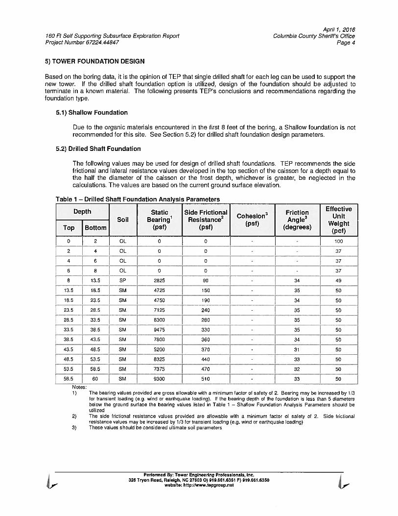
5.2) Drilled Shaft Foundation
The following values may be used for design of drilled shaft foundations. TEP recommends the sidefrictional and lateral resistance values developed in the top section of the caisson for a depth equal tothe half the diameter of the caisson or the frost depth, whichever is greater, be neglected in thecalculations. The values are based on the current ground surface elevation.
Table 1 — Drilled Shaft Foundation Analysis Parameters
Depth Static Side Frictional . FrictionEffective
. . 2 Cohesion UnitSoil Bearing Resistancesf)
AngleWei ht
Top Bottom (psf) (psf) (degrees)(pct)
0 2 CL 0 0 - — 100
-a-- CL ]0 0 - - - 37
4 6 CL 0 0 -— - - 37
6 8 CL 0 0 - - 37
8 13.5 SP 2825 90 - 34 49
13.5 18.5 SM 4725 150 - 35 — 50
18.5 23.5 SM 4750 f 190 - 34 50
23.5 28.5 - SM- [ 35
28.5 33.5 SM 8300 280- j 35 50
38 SM -- 9475 330 - [35 50
38.5 43.5 SM 7800 360 - — 34 50
43.5 48.5 SM 5200 370 - 31 50 —
48.5 53.5 SM 8325 440 - 33 50
55 58.5 SM 7375 — 470 - 32 50
58.5 60 SM 9300 510 - 33 50
Notes:1) The bearing values provided are gross allowable with a minimum factor of safety of 2. Bearing may be increased by 1/3
for transient loading (e.g. wind or earthquake loading). If the bearing depth of the foundation is less than 5 diametersbelow the ground surface the bearing values listed in Table 1 — Shallow Foundation Analysis Parameters should beutilized
2) The side frictional resistance values provided ate allowable with a minimum factor of safety of 2. Side frictionalresistance values may be increased by 1/3 for transient loading (e.g. wind or earthquake loading)
3) These values should be considered ultimate soil parameters
Performed By: Tower Engineering Professionals, Inc.326 Tryon Road, Raleigh, NC 276030) 919.661.6351 F) 919.661.6350
website: http:/twww.tepgroup.net
April 7, 2076760 Ft Self Supporting Subsurface Exploration Report Columbia County Sheriff’s OfficeProject Number 67224.4484 7 Page 5
6) SOIL RESISTIVITY
Soil resistivity was performed at the TEP laboratory in accordance with ASIM G187-05 (Standard Test Methodfor Measurement of Soil Resistivity Using the Two Electrode Soil Box Method). Test results indicated a result of100,000 ohms/cm.
Performed By: Tower Engineering Professionals, Inc.326 Tryon Road, Raleigh, NC 276030) 919.661.6351 F) 919.661.6350
website: http://www.tepgroup.net
April 1, 2076760 Ft Sell Supporting Subsurlace Exploration Report Columbia County Sherifl’s OlliceProject Number 6722444847 Page 6
7) CONSTRUCTION CONSIDERATIONS - DRILLED SHAFTS
Based on TEP’s experience a conventional drilled shaft rig (Hughes Tool LDH or equivalent) can be used toexcavate to the termination depth of TEP’s boring. An earth auger can typically penetrate the materialsencountered to the termination depth of the boring with moderate difficulty. Materials below the auger refusaldepth may require a coring bit or roller-bit to remove the material. Special excavation equipment may benecessary for a shaft greater that 60-inches in diameter. If hole collapse is encountered during construction, thedesign and geotechnical engineers should be contacted immediately to make any necessary adjustments.
Due to the subsurface water and the sandy soil, the contractor may elect to utilize the “slurry” method for shaftconstruction. The following are general procedure recommendations in drilled shaft construction using the“slurry” method:
1) Slurry drilled shafts are constructed by conventional caisson drill rigs excavating beneath a drilling mudslurry. Typically, the slurry is introduced into the excavation after the groundwater table has beenpenetrated and/or the soils on the sides of the excavation are observed to be caving-in. When thedesign shaft depth is reached, fluid concrete is placed through a tremie pipe at the bottom of theexcavation.
2) The slurry level should be maintained at a minimum of 5 feet or one shaft diameter, whichever isgreater, above the subsurface water level.
3) Inspection during excavation should include verification of plumbness, maintenance of sufficient slurryhead, monitoring the specific gravity, pH and sand content of the drilling slurry, and monitoring anychanges in the depth of the excavation between initial approval and prior to concreting.
4) A removable steel casing may be installed in the shaft to prevent caving of the excavation sides due tosoil relaxation. Loose soils in the bottom of the shaft should be removed.
5) The specific gravity or relative density of the drilling mud slurry should be monitored from the initialmixing to the completion of the excavation. An increase in the specific gravity or density of the drillingslurry by as much as 10 percent is indicative of soil particles settling out of the slurry onto the bottom ofthe excavation. This settling will result in a reduction of the allowable bearing capacity of the bottom ofthe drilled shaft.
6) After approval, the drilled shaft should be concreted as soon as practical using a tremie pipe.
7) For slurry drilled shafts, the concrete should have a 6 to 8 inch slump prior to discharge into the tremie.The bottom of the tremie should be set at about one tremie pipe diameter above the excavation. Aclosure flap at the bottom of the tremie should be used, or a sliding plug introduced into the tremiebefore the concrete, to reduce the potential for the concrete being contaminated by the slurry. Thebottom of the tremie must be maintained in concrete during placement, which should be continuous.
8) The protective steel casing should be extracted as concrete is placed. A head of concrete should bemaintained above the bottom of the casing to prevent soil and water intrusion into the concrete belowthe casing.
9) Additional concrete should be placed via the tremie causing the slurry to overflow from the excavation inorder to reduce the likelihood of slurry pockets remaining in the drilled shaft.
If variability in the subsurface materials is encountered, a representative of the Geotechnical Engineer shouldverify that the design parameters are valid during construction. Modification to the design values presentedabove may be required in the field.
Performed By: Tower Engineering Professionals, Inc.326 Tryon Road, Raleigh, NC 276030) 919.661.6351 F) 919.661.6350
website: http://www.tepgroup.net
April 7, 2076760 Ft Self Supporting Subsurface Exploration Report Columbia County Sheriff’s OfficeProject Number 67224.4484 7 Page 7
APPENDIX A
BORING LAYOUT
Performed By: Tower Engineering Professionals, Inc.326 Tryon Road, Raleigh, NC 276030) 919.661.6351 F) 919.661.6350
website: http:/ww.tepgroup.net
PENGRASSED
ARE
BORING LAYOUT
SCALE: N.TS.
SHERIFF’S OFFICEp 544W FUfl 445744
PREPARED BY: PREPARED FOR: PROJECT INFORMATION:REVISION: 0
TOWER ENGINEERING PROFESSIONALS COLUMBIA COUNTY TEP JOB #: 7224.44ô47326 TRYON ROAD SHERIFF OFFICE SHEET NUMBER:
RALEIGH, NC 27603
I(919)661.63514917 US—gO East 4917 US—9O East ClLAKE CITY. FL 32055 LAKE CITY, FL 32055www.tepgroup.net(386) 752—9212 (COLUMBIA COUNTY)
WOODEDARE A—
160’SELF—SUPPORT TOWER
XIS TIN CGRAVELACCESSROAD
April 7, 2076760 Ft Sell Supporting Subsurface Exploration Report Columbia County Sheriffs OfficeProject Number 6722444847 Page 8
APPENDIX B
BORING LOG
Performed By: Tower Engineering Professionals, Inc.326 Tryon Road, Raleigh, NC 276030)919.661.6351 F) 919.661.6350
website: http://www.tepgroup.net
-10
-25
-30
35
-40
-45
50
55
60
-65
Tower Engineering Professionals, Inc.326 Tryon Road LOG OF BORING B-iF(
Raleigh, NC 276031 OF 1Telephone: 919.661.6351
PROJECT SITEID TEPNO.:Email: [email protected] Columbia County Sheriffs Office 67224.44847
DATE STARTED DRILLING METHOD HOLE SIZE CITY, STATE
3/15/2016 Mud Rotary 2-3/4in Lake Cjy, FloridaDATE COMPLETE HAMMER WEIGHT/FALL r HAMMER TYPE TOTAL DEPTH DRILL RIG TYPE
3/15/2016 l4OIbs/30in Rope & Cathead 60.0 Fr Bug_______GROUND EL. LOGGED BY CHECKED BY BACKFILL DEPTH/EL. GROUNDWATER
JEL TAD Grout 3.3/ AIDBORING LOCATION
— Mjacent to the centerline of the proposed tower — — —
3- I 03-Ui F- LU I 0 z 03] H3- 0 z u- I L LUQz___
— 3-O.-.I3- U 0 3- F-u- 3-F- UuD I 0 3- 3-
DESCRIPTION AND CLASSIFICATION REMARKS Lii LU Z 0z .U1
U 0 H OzLUi 1 - 0— - 3] 0 H
Ui 0 Z3] 3- DH< < 3- 3-D LULU LU LU
Si 24 4-5-4-4
S2 24 3-4-3-5(7)
S3 24 4-4-5-4
S4 24 5-5-4-6
6-5-6-6
r
5
0.0-4.0: Loose, gray, tine to medium, poorlygraded SAND (OL), little organiCs, trace roots,trace silt, wet
4.0-6.0: little silt
15
20
S6 18 6-6-7
Th1-
S7 18 3-5-7—
—
2J
S8 18 6-6-9(15)
S9 18 5-9-716)_
SlO 18 6-8-11
1
(19)
Sli 18 7-7-9(16)
512 18 6-5-61)
Si 3 5-7-7(14)
. 6.0-8.0: Loose, grayish brown, fine to medium,LLltySAND (OL), little organics, wet
8.0-13.5: Medium dense, light brown, fine tomedium, poorly graded SAND (SP), trace silt,trace particulate organics, wet
13.5-48.5: Medium dense, white, tine, silty SAND(SM), wet
X
z,
z,.,
z.
X
XL
Z 48.5-60.0: light brown
z
I-S15 7-7-9(16) 60.0: Boring Terminated
, Tower Engineering Professionals, Inc.
326 Tryon Road
Raleigh, NC 27603 Key to Soil Symbols and TermsTelephone: 919-661-6351
Email: [email protected]
TERMS DESCRIBING CONSISTENCY OR CONDITION GENERAL NOTESCOARSE-GR.AINED SOILS (major portions retained on No. 200 sieve): includes (1) clean 1. Classifications are bases on the Unifiedgravel and sands and (2) silty or clayey gravels and sands. Condition is rated according to Soil Classification System and includerelative density as determined by laboratory tests or standard penetration resistance tests. consistency, moisture, and color. FieldDescriptive Terms SPT Blow Count descriptions have been modified to reflectVery Loose < 4 results of laboratory tests where deemedLoose 4 to 10 appropriate.Medium Dense 11 to 30Dense 31 to 50 2. Surface elevations are based onVery Dense > 50 topographic maps and estimated locationsFINE-GRAINED SOILS (major portions passing on No. 200 sieve): includes (1) inorganic and and should be considered approximate.organic silts and clays (2) gravelly, sandy, or silty clays, and (3) clayey silts. Consistency is ratedaccording to shearing strength, as indicated by penetrometer readings, SPT blow count, or 3. Descriptions on these boring logs applyunconfined compression tests. only at the specific boring locations and atDescriptive Terms SPT Blow Count the time the borings were made. They areVery Soft < 2 not guaranteed to be representative ofSoft 2 to 4 subsurface condition at other locations orMedium Stiff 5 to 8 times.Stiff 9to15Very Stiff 16 to 30Hard > 30
Symbo Typical Names Sampler Symbols
GW Well-graded gravels, gravel-sand mixtures, little or no fines Split Spoon
‘. c GP Poorly-graded gravels little or no fines/sandsStandard Penetration Test
(SPI)
jjc GM Silty gravels, gravel-sand-silt mixtures • Pushed Shelby Tube
GC Clayey gravels, gravel-sand-silt mixtures Jj Auger Cuttings
SW Well-graded sands, gravelly sands, little or no fines Grab Sample
SP Poorly-graded sands little or no fines/sands/gravels Dynamic Cone Penetrometer
SM Silty sands sand silt mixtures Hand Auger
SC Clayey sands, sand-clay mixtures H Rock Core
I i’1 Inorganic silts and very fine sands, rock floor, silty or clayey
,]j MLfine sands or clayey silts with slight plasticity
Log Abbreviations, CL0 mplasticity, gravelly clays,
ATD - At Time of Drilling
——. . AD - After Drilling—— CL Organic silts and organic silty clays of low plasticity
J
EOD - End of DrillingInorganic silts micaceous or distomaceous fine sandy or silty
MHsoils, elastic silts RMR - Rock Mass Rating
“ WOH - Weight of HammerCH Inorganic clays of high plasticity, fat clays
WOR - Weight of Rod
OH Organic clays of medium to high plasticity, organic silts REC - Rock Core Recovery
t- “ RQD - Rock Quality Designation, ,, PT Peat and other highly organic soils
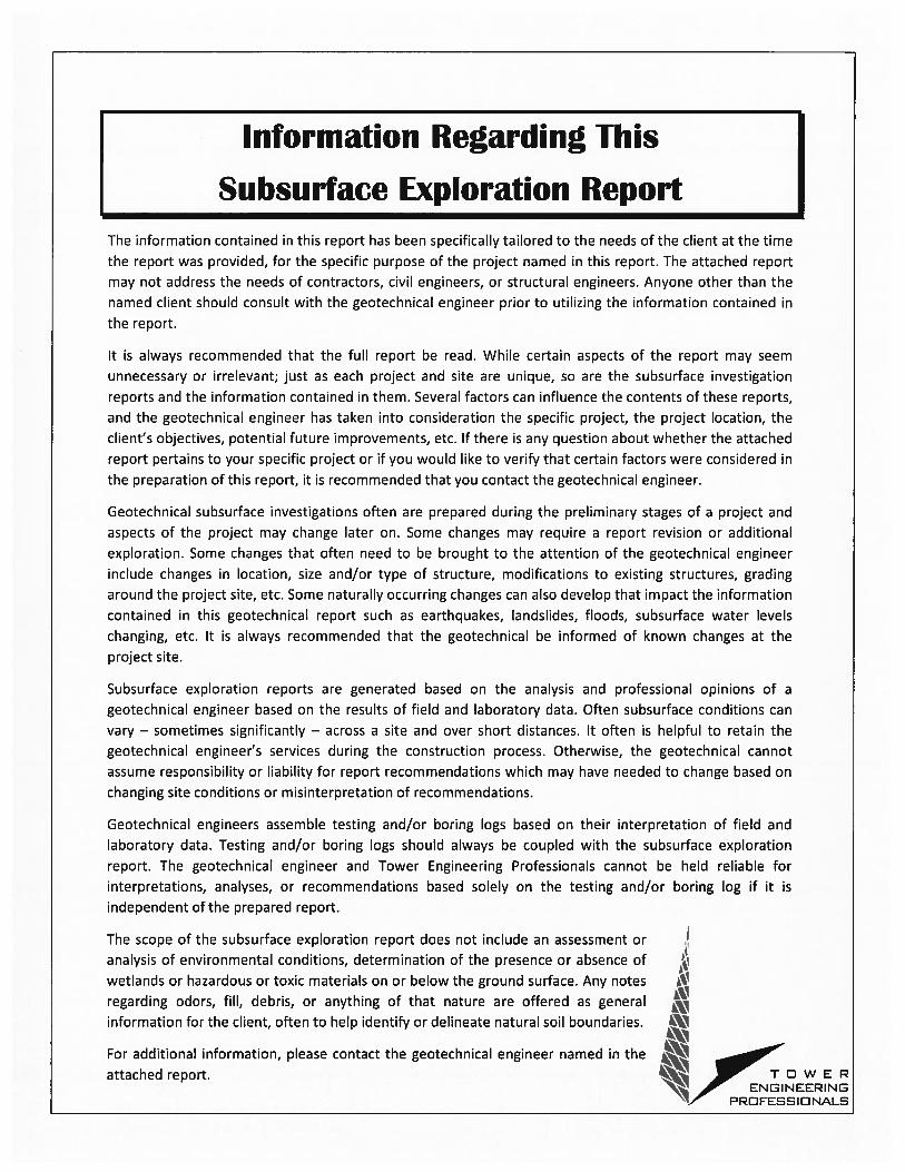
Information Regarding This
Subsurface Exploration ReportThe information contained in this report has been specifically tailored to the needs of the client at the time
the report was provided, for the specific purpose of the project named in this report. The attached report
may not address the needs of contractors, civil engineers, or structural engineers. Anyone other than the
named client should consult with the geotechnical engineer prior to utilizing the information contained in
the report.
It is always recommended that the full report be read. While certain aspects of the report may seem
unnecessary or irrelevant; just as each project and site are unique, so are the subsurface investigation
reports and the information contained in them. Several factors can influence the contents of these reports,
and the geotechnical engineer has taken into consideration the specific project, the project location, the
client’s objectives, potential future improvements, etc. If there is any question about whether the attached
report pertains to your specific project or if you would like to verify that certain factors were considered in
the preparation of this report, it is recommended that you contact the geotechnical engineer.
Geotechnical subsurface investigations often are prepared during the preliminary stages of a project and
aspects of the project may change later on. Some changes may require a report revision or additional
exploration. Some changes that often need to be brought to the attention of the geotechnical engineer
include changes in location, size and/or type of structure, modifications to existing structures, grading
around the project site, etc. Some naturally occurring changes can also develop that impact the information
contained in this geotechnical report such as earthquakes, landslides, floods, subsurface water levels
changing, etc. It is always recommended that the geotechnical be informed of known changes at the
project site.
Subsurface exploration reports are generated based on the analysis and professional opinions of a
geotechnical engineer based on the results of field and laboratory data. Often subsurface conditions can
vary — sometimes significantly — across a site and over short distances. It often is helpful to retain the
geotechnical engineer’s services during the construction process. Otherwise, the geotechnical cannot
assume responsibility or liability for report recommendations which may have needed to change based on
changing site conditions or misinterpretation of recommendations.
Geotechnical engineers assemble testing and/or boring logs based on their interpretation of field and
laboratory data. Testing and/or boring logs should always be coupled with the subsurface exploration
report. The geotechnical engineer and Tower Engineering Professionals cannot be held reliable for
interpretations, analyses, or recommendations based solely on the testing and/or boring log if it is
independent of the prepared report.
The scope of the subsurface exploration report does not include an assessment or
analysis of environmental conditions, determination of the presence or absence of
wetlands or hazardous or toxic materials on or below the ground surface. Any notes
regarding odors, fill, debris, or anything of that nature are offered as generalinformation for the client, often to help identify or delineate natural soil boundaries.
For additional information, please contact the geotechnical engineer named in the
attached report. T D W E PENGINEERING
PRDFESSIDNALS


![Heritage.] 0 50 100 200 Corporate Office Professional ...€¦ · Corporate Office Professional Office Retail/ Office Restaurant Retail 400 Hotel Multi-Family SF Attached (Townhome)](https://img.pdfslide.net/doc/110x75/5eaca43b378e8f35681c762f/heritage-0-50-100-200-corporate-office-professional-corporate-office-professional.jpg)