Embed Size (px)
Citation preview
Volume 6, Issue 3, March – 2021 International Journal of Innovative Science and Research Technology
ISSN No:-2456-2165
IJISRT21MAR017 www.ijisrt.com 35
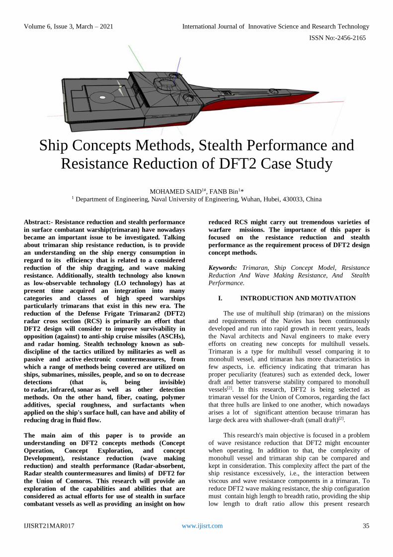
Ship Concepts Methods, Stealth Performance and
Resistance Reduction of DFT2 Case Study
MOHAMED SAID1#, FANB Bin1* 1 Department of Engineering, Naval University of Engineering, Wuhan, Hubei, 430033, China
Abstract:- Resistance reduction and stealth performance
in surface combatant warship(trimaran) have nowadays
became an important issue to be investigated. Talking
about trimaran ship resistance reduction, is to provide
an understanding on the ship energy consumption in
regard to its efficiency that is related to a considered
reduction of the ship dragging, and wave making
resistance. Additionally, stealth technology also known
as low-observable technology (LO technology) has at
present time acquired an integration into many
categories and classes of high speed warships
particularly trimarans that exist in this new era. The
reduction of the Defense Frigate Trimaran2 (DFT2)
radar cross section (RCS) is primarily an effort that
DFT2 design will consider to improve survivability in
opposition (against) to anti-ship cruise missiles (ASCHs),
and radar homing. Stealth technology known as sub-
discipline of the tactics utilized by militaries as well as
passive and active electronic countermeasures, from
which a range of methods being covered are utilized on
ships, submarines, missiles, people, and so on to decrease
detections (that is, being invisible)
to radar, infrared, sonar as well as other detection
methods. On the other hand, fiber, coating, polymer
additives, special roughness, and surfactants when
applied on the ship's surface hull, can have and ability of
reducing drag in fluid flow.
The main aim of this paper is to provide an
understanding on DFT2 concepts methods (Concept
Operation, Concept Exploration, and concept
Development), resistance reduction (wave making
reduction) and stealth performance (Radar-absorbent, Radar stealth countermeasures and limits) of DFT2 for
the Union of Comoros. This research will provide an
exploration of the capabilities and abilities that are
considered as actual efforts for use of stealth in surface
combatant vessels as well as providing an insight on how
reduced RCS might carry out tremendous varieties of
warfare missions. The importance of this paper is
focused on the resistance reduction and stealth
performance as the requirement process of DFT2 design
concept methods.
Keywords: Trimaran, Ship Concept Model, Resistance
Reduction And Wave Making Resistance, And Stealth
Performance.
I. INTRODUCTION AND MOTIVATION
The use of multihull ship (trimaran) on the missions
and requirements of the Navies has been continuously
developed and run into rapid growth in recent years, leads
the Naval architects and Naval engineers to make every
efforts on creating new concepts for multihull vessels.
Trimaran is a type for multihull vessel comparing it to
monohull vessel, and trimaran has more characteristics in
few aspects, i.e. efficiency indicating that trimaran has
proper peculiarity (features) such as extended deck, lower
draft and better transverse stability compared to monohull vessels[2]. In this research, DFT2 is being selected as
trimaran vessel for the Union of Comoros, regarding the fact
that three hulls are linked to one another, which nowadays
arises a lot of significant attention because trimaran has
large deck area with shallower-draft (small draft)[2].
This research's main objective is focused in a problem
of wave resistance reduction that DFT2 might encounter
when operating. In addition to that, the complexity of
monohull vessel and trimaran ship can be compared and
kept in consideration. This complexity affect the part of the ship resistance excessively, i.e., the interaction between
viscous and wave resistance components in a trimaran. To
reduce DFT2 wave making resistance, the ship configuration
must contain high length to breadth ratio, providing the ship
low length to draft ratio allow this present research
Volume 6, Issue 3, March – 2021 International Journal of Innovative Science and Research Technology
ISSN No:-2456-2165
IJISRT21MAR017 www.ijisrt.com 36
accessing the unreachable area of DFT2 compared to the
one of monohull with the same length or dimensions.
DFT2 will not only consider the reduction of ship
resistance, enumerate the vessel concept methods, but also
stealth performance (Stealth technology). Taking into
account the use of stealth technology also known as LO
technology, in this research is a way to decrease high level of radar detection. LO technology is a military sub-
discipline used during mission tactics, as well as on passive
and active electronic countermeasures. Using this
technology, DFT2 will include range of methods that will
permit the ship to conduct less visibility or being
undetectable to radar, infrared, sonar and other detection
methods carried out by surface warfare.
The term "soft kill" performance is area for conducting
research as it has received an important attention (thoughts)
considered as an ongoing effort of expendable chaff systems by decreasing DFT2's radar crass section (RCS)
significantly. The chaff cloud will behave as defenses chaff
to mask the ship from active radar of distant ships, close-in
quick-blooming chaff and flares for confusing radar in
activity. In another word, the chaff cloud would become a
more attractive target to the missile seeker and therefore
more effective at seducing the missile away from the ship[5].
II. CONCEPT OPERATION, CONCEPT
EXPLORATION AND CONCEPT
DEVELOPMENT
I.1 Concept Operation
DFT2’s concept of operations will be based on the
Mission Need Statement (MNS) for ship Intelligence
Surveillance Reconnaissance (ISR), search and rescue, drug
Interdiction and Smuggling, and maintain the safeguard of
the country's sea state. The ship must operate from the Naval
base on the main island or on each one of the sub-bases
located on the other islands, up to the high seas
environment. The islands are approximately distanced
between 21.6 nautical miles, 43.2 nautical miles, and 108
nautical miles from one island to another. DFT2 must be
able to carry on an ISR of about 7 to 10+ days on a coastal zone and littoral, and also 30+ days on high seas [8][10].
The primary DFT mission serviceable areas and
capabilities include[8]:
Port and Coastal Security (PCS)
Search And Rescue (SAR)
Drug Interdiction (DRUG)
Migrant Interdiction (AMIO)
Protect Living Marine Resources (LMR)
Other Law Enforcement (OLE)
Secondary: Defense Readiness (DR)
Life circle or service life for the ship design is
projected to be 30 to 40 years. This life circle is an extended
timeframe which providing flexibility in improving,
maintaining and promoting the ship's capability over time is
demanded[7]. Some missions are to consider, it comprises
Surface Action Group (SAG), Homeland shield, Self-
operation missions, and escort (civilian ships, merchant
ships, and commercial ships). The ship will furnish OPs
within these mission area such as AAW, ASuW(SUW),
GMLS, including ISR and LAMPS. DFT2 will also provide mission operations independently regarding, supporting
special operations, search and rescue, humanitarian
operations support, and peacetime presence. Table 1 give a
simple description of priority capability:
Table 1 Description of priority capability
Priority capability description Threshold system (equipment used)
1 Maintain AAW, Guided Missile Launching System
(GMLS)
32cell VLS, SRBOC, SLQ-32(V2), 160 cells MK57 + 8 cells
KEI, SPS-73 or the Type 751/762 radar
2 Maintain ASuW in deep or shallow waters 1x155m AGS, SPS-73, Small Arms, TISS, FLIR, GFCS, 2x7m
3 Mission package (MP): BT, ASuW, ISR LCS MP
4 Mobility, LAMPS 25 to 36 knt, 2160 nm and above, 7 to 30+ days, LAMPS
haven (flight deck)
5 Survivability and self-defense Mine detection sonar, CIWS
6 Core ISR (C4ISR with sequences) C4i system(Enhanced C4ISR / Basic C4ISR)
7 Core ASuW 57 mm gun, 2x50 Caliber gun, 1x155m AGS, SPS-73, Small
Arms, TISS, FLIR, GFCS, 2x7m, RHIB, MK46 Mod1 3x
CIGS
I.2 Concept Exploration
Trade-off is being conducted through this process and
DFT2 design space has been found as well by the use of
computing methods such as Matlab software to generate a
multiple-objective generic optimization (Brown and Salcedo
2002). On [7] a simple ship synthesis model was used to
balance the design, to assess feasibility and calculate cost,
risk and effectiveness. In this concept a series of non-dominated frontiers are given as the DFT2 alternative design
are classed in the order of cost-risk-effectiveness. A non-
dominated frontier (NDF) represents ship designs in the
design space that have the highest effectiveness for a given
cost and risk[8]. Concept exploration yields one concept
baseline design or more than one, which is completed in
concept development and preliminary design. Contract
design constitute the finishing stage of the full specifications
for the ship, which point a contract is made with shipbuilders for the construction of the ship. The last stage
Volume 6, Issue 3, March – 2021 International Journal of Innovative Science and Research Technology
ISSN No:-2456-2165
IJISRT21MAR017 www.ijisrt.com 37
of design is done by ship builders in relation with the
constructor of the ship, which is the detail design. To
complete these five methods, the ship builders (ship
designer) and the constructor of the ship can go through 16
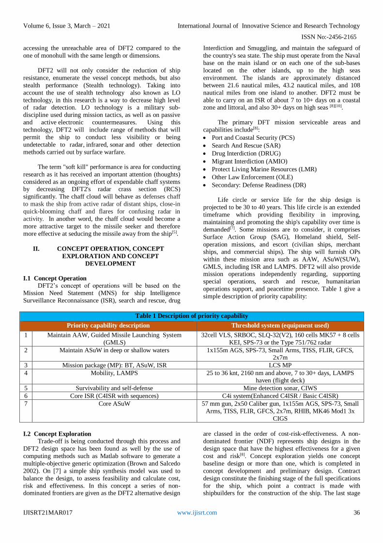
to 20 years to complete the work as shown in Figure 1[7].
Figure 1 - Concept Exploration (Brozn 2005) [8]
In this process, our point of view is to keep in mind the
methods and approach that is being carried out on the design
method of ASC vessel, so that developing reference
missions, required operational capabilities, identifying
applicable technologies and developing an effectiveness
model will be carried out. In addition to that, a technology
risk model and large design space are defined so that a broad
range of technologies with different risk may be considered.
The mission scenarios developed are unique to the Design
Reference Missions scenario that DFT2 requires Table 2.
Table 2- SAG and BMD Mission
Days Mission Scenarios
1 to 2 Cruise from the main base to the other sub-bases/ board crews
3 to 6 Port of call, replenishment forces and embark modules, ASuW, AAW, SY-1, SS-N-22,
C-802KD
7 to 12 Carry out ops for AAW, ASuW, and SY-1, SS-N-22, C-802KD
13 to 14 Engage air threat self-defense
15 to 20 POC/ maintenance and repairs
21 to 22 Conduct CIWS/ mine detection and mine avoidance operations
23 to 26 Carry out operations against littoral threats
27 to 29 Engage anti-missile operations (air, surface, and underwater)
30+ POC/ general maintenance,/refueling and replenish forces
I.2.1 Trade-Off Studies, Technologies, concepts, and
Design variables
Existing technologies and concepts necessary to
provide mandatory functional capabilities are identified and
defined in terms of performance, cost, risk, and ship
characteristics (weight, area, volume, power). On [8] Trade-
off studies are performed using technology and other
concept design variables used to select trade-off options in a
multi-objective genetic optimization (MOGO) for the total
ship design. Form Rhino software (Figure 2) is describing a
complete hull form of DFT2, and technology, concept trade
spaces, and parameters are described in the following
sections.

Volume 6, Issue 3, March – 2021 International Journal of Innovative Science and Research Technology
ISSN No:-2456-2165
IJISRT21MAR017 www.ijisrt.com 38
Figure 2 - DFT parent Hull Form (RHNO)
I.2.2 Hull Form Alternatives (HFA)
To get DFT2 hull form, three main non-dimensional
numbers are used. They are Transport Efficiency (TE),
Transport Factor (TF), and Froude number (Fr). The
associated equations are presented on the next page [10] [25].
However, the TF concept was utilized for choosing
ship types that can hold a needed load at a high speed. TF is
a non-dimensioned between, speed, endurance, and
propulsion power, that is estimated by using one of the
following equations [4][24]:
TF =𝑊𝐹𝐿 𝑉𝑆
𝑆𝐻𝑃𝑇𝐼
=(𝑊𝐿𝑆 + 𝑊𝐹𝑢𝑒𝑙 + 𝑊𝐶𝑎𝑟𝑔𝑜)𝑉𝑆
𝑆𝐻𝑃𝑇𝐼
TF = (5.052𝐾𝑊
𝑀𝑇 × 𝐾𝑛𝑡)
∆𝑉𝑆
𝑊𝑃𝑅= 30.7@25𝑘𝑛𝑡
Therefore, the following Table 5 enumerate the
hullform from preliminary assessment, which provide result
to conclude the hullform estimation from different
comparisons.
I.2.3 DFT2 Hull Form Concept Exploration Design
Space Summary
The following Table 6 summarizes the hull form
design space for DFT2 after assessment and calculation.
Table 6 – Baseline Hullform Characteristics
Hull Form Type Trimaran
Displacement (Mt) 907.185-1814.369 (Mt)
L 80-100 m
B 19.24-24.411 m
D 4.8 - 10.4m
T 4.8 - 10.4m
CP 0.45-0.53
CX 0.65-0.74
CRD 0.7-1.0
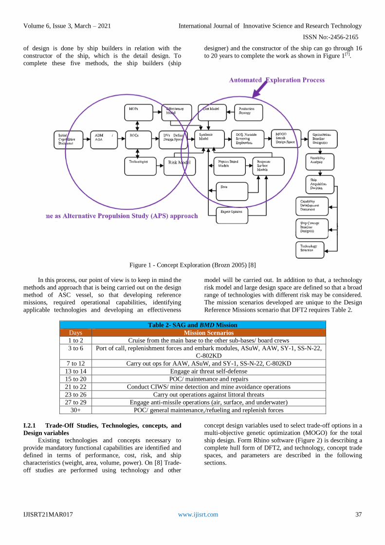
I.2.4 Machinery Plant Alternatives
Power transmission, power plant, and propulsor
(thruster) alternatives options are well thought-out in the
process of DFT2 ship design throughout this section.
The vessel is provided by two power transmission
alternatives: In (1) is a mechanical drive system, from which
the main engines are joined to the propulsor in a way of a
traditional reduction gear with a turbo generator to increase
power; the second in (2) is an integrated power system
(IPS), which is a power plant that will conducts the
generators, and allows the ship to acquire electricity
supplying to the power motors (advanced AC induction
motors) joined with the propulsors. The mechanical driving
system will concentrate on the currently standard on all Chinese Navy conventional combatants, also using the IPS
as it can guarantee more flexibility and easier maintenance,
and grasps the support of Navies for future projects. The
mission of DFT2 demands that the ship must be capable to
carry out operations at high speeds, so a high power
performance and density configuration is needed and
necessary. In addition to that not only alternatives with gas
turbine engines will be considered but also diesel engines
will be kept in mind to be used as shown in the following
figure.
Table 5-Hullform Preliminary Assessment Summary
RCS Cost Hull
length
Seakeeping
stability
Large
compartment for
machinery space
Reliability
Helicopter
mission and
others
Total
assessment
Catamarans 2 2 2 3 3 4 3 19
Mono-hulls 4 4 3 2 3 3 3 22
Surface effect
ships 3 3 1 1 2 2 1 13
Trimarans 2 2 3 4 4 4 4 23
Volume 6, Issue 3, March – 2021 International Journal of Innovative Science and Research Technology
ISSN No:-2456-2165
IJISRT21MAR017 www.ijisrt.com 39
Figure 3 - DFT Propulsion Trade -Off Alternatives
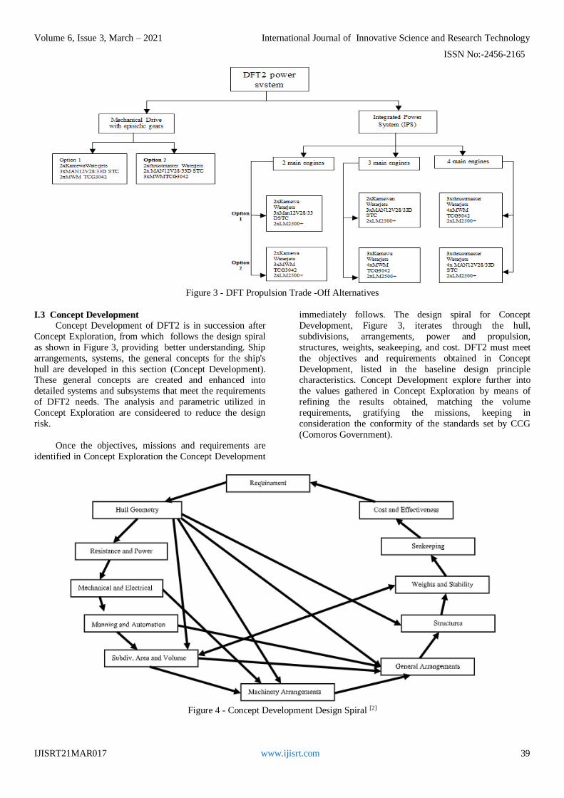
I.3 Concept Development
Concept Development of DFT2 is in succession after
Concept Exploration, from which follows the design spiral
as shown in Figure 3, providing better understanding. Ship
arrangements, systems, the general concepts for the ship's
hull are developed in this section (Concept Development). These general concepts are created and enhanced into
detailed systems and subsystems that meet the requirements
of DFT2 needs. The analysis and parametric utilized in
Concept Exploration are consideered to reduce the design
risk.
Once the objectives, missions and requirements are
identified in Concept Exploration the Concept Development
immediately follows. The design spiral for Concept
Development, Figure 3, iterates through the hull,
subdivisions, arrangements, power and propulsion,
structures, weights, seakeeping, and cost. DFT2 must meet
the objectives and requirements obtained in Concept
Development, listed in the baseline design principle characteristics. Concept Development explore further into
the values gathered in Concept Exploration by means of
refining the results obtained, matching the volume
requirements, gratifying the missions, keeping in
consideration the conformity of the standards set by CCG
(Comoros Government).
Figure 4 - Concept Development Design Spiral [2]
Volume 6, Issue 3, March – 2021 International Journal of Innovative Science and Research Technology
ISSN No:-2456-2165
IJISRT21MAR017 www.ijisrt.com 40
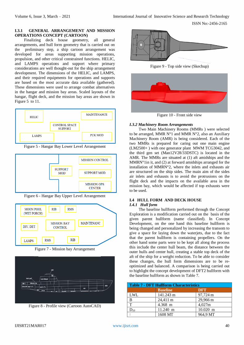
I.3.1 GENERAL ARRANGEMENT AND MISSION
OPERATIONS CONCEPT (CARTOON)
Finalizing deck house geometry, all general
arrangements, and hull form geometry that is carried out on
the preliminary step, a ship cartoon arrangement was
developed for areas supporting mission operations,
propulsion, and other critical constrained functions. HELIC,
and LAMPS operations and support where primary considerations are well thought-out for the ship arrangement
development. The dimensions of the HELIC, and LAMPS,
and their required equipments for operations and supports
are based on the most accurate data available (gathered).
These dimensions were used to arrange combat alternatives
in the hangar and mission bay areas. Scaled layouts of the
hangar, flight deck, and the mission bay areas are shown in
Figure 5 to 11.
Figure 5 - Hangar Bay Lower Level Arrangement
Figure 6 - Hangar Bay Upper Level Arrangement
Figure 7 - Mission bay Arrangement
Figure 8 - Profile view (Cartoon AutoCAD)
Figure 9 - Top side view (Skechup)
Figure 10 - Front side view
I.3.2 Machinery Room Arrangements
Two Main Machinery Rooms (MMRs ) were selected
to be arranged, MMR N°1 and MMR N°2, also an Auxiliary
Machinery Room (AMR) is being considered. Each of the
two MMRs is prepared for caring out one main engine
(LM2500+ ) with one generator plant MWM TCG3042, and
the third gen set (Man12V28/33DSTC) is located in the
AMR. The MMRs are situated at (1) aft amidships and the
MMRN°1in it, and (2) at forward amidships arranged for the
installation of MMRN°2, where the inlets and exhausts air are structured on the ship sides. The main aim of the sides
air inlets and exhausts is to avoid the protrusions on the
flight deck and the impacts on the available area in the
mission bay, which would be affected if top exhausts were
to be used.
I.4 HULL FORM AND DECK HOUSE
I.4.1 Hull form
The baseline hullform performed through the Concept
Exploration is a modification carried out on the basis of the
given parent hullform (name classified). In Concept Development, on the one hand this baseline hullform is
being changed and personalized by increasing the transom to
give a space for laying down the waterjets, due to the fact
that the parent hullform is containing propellers. On the
other hand some parts were to be kept all along the process
this include the center hull beam, the distance between the
outer hulls and center hull, creating a stable top deck of the
aft of the ship for a weight reduction. To be able to consider
these changes, the hull form dimensions are to be re-
optimized and balanced. A comparison is being carried out
to highlight the concept development of DFT2 hullform with
the baseline hullform as shown in Table 7.
Table 7 - DFT Hullform Characteristics
Baseline DFT
LWL 141.243 m 97,724 m
B 24,411 m 29,966 m
T 4.368 m 4,027m
D10 11.240 m 10.020 m
1608 MT 964,9 MT

Volume 6, Issue 3, March – 2021 International Journal of Innovative Science and Research Technology
ISSN No:-2456-2165
IJISRT21MAR017 www.ijisrt.com 41
I.4.2 Deck house
The deck house is arranged for flight control, chart
room, aviation hangar, and the bridge, from which LAMPS,
HELIC, and their modules for support and holders are laid
down. The bridge (pilot house) is located in the forward
upper middle of the deckhouse as Figure 12 enumerates the
bridge location, where a good and strategic position for
acquiring a necessary forward visibility. On the aft end of the deck house is arranged the Flight and Recovery Control
(FARC) department, where the main purpose is to provide
supports to the LAMPS and HELIC operations. An
Advanced Enclosed Mast/Sensor (AEM/S) for DFT2 from
which Radar and the different antennas are set up within it,
is located on the top forward of the bridge (deckhouse) as
shown in Figure 13 which is displaying a profile view of the
AEM/S located on the deck elevation.
A Surface Search Radar (SSR) responsible of the
navigation and surveillance by means of configuration for DFT2 applications, and a radar video from consoles display
that provides a means of performing manual radar search,
and detection and tracking functions is considered. This
radar can either be the SPS-73 or the Type 751/762 radar
incorporated within the AEM/S encloses the upper deck.
The SPS-73 or the Type 751/762 volume will be controlling
the ship's deck height and width. A Powerful shipboard
Protection as a SLQ-32 EW system located on the lower
deck of AEM/S providing early warning, early
identification, with a direct finding capability for
simultaneous multiple threats which. The upper deck right
side internal shell of AEM/S is appointed with an advanced hybrid frequency-selective surface that allows the ship’s
own radar in and out, but not foreign radar[10].
Figure 12 - Bridge location (Sketchup)
Figure 13 - AEM/S
III. RESISTANCE REDUCTION AND WAVE
MAKING RESISTANCE
II.1. Ship resistance
Ship resistance can be defined as a force required to
drag (tow) the ship without interference from pulling ship,
this resistance is characterized by a combination of four
resistance and can be specified as[34]:
Frictional resistance, which occurs when the ship hull
and the viscous fluid are wrapped up with a
friction layer formation
Wave making resistance, which is generally
characterized by the creation of waves at free
surface due to the energy transferred by the ship
Eddy resistance, this is described as the flow separation
that occurs due to non-streamline flow at the ship stern
Air resistance, which is described as the load which the
windage area of hull and superstructure experience from
the wind
The sum of Wave making resistance and eddy
resistance is known as residuary resistance, and apart from
the above stated, the following statements are also
considered in this section for ship resistance[34]:
Waves and the wave breaking resistance
Resistance for a ship sailing in a seaway
Resistance due to ship's turning
Shallow water resistance
The frictional resistance component is calculated on the basis of Reynolds number and wetted surface area
together with a hull roughness allowance. EHP = ACT (VS)
^3, (A →Wetted Surface Area)
II.2. Resistance reduction
For a general understanding on the above mentioned,
this section will provide ways on how DFT2 resistance is
possible to be reduced. Firstly, considering
Bülent danişman , Ömer gören , and Sander çalişal (2002),
resistance reduction of the ship is possible by means of
raising (increasing) the beam whereas smoothing the shoulders of the ship in a moderate way with a relative
increased Froude numbers, more detail in the following
sections. Then, a mathematical justification carried out, by
the method of Michell’s integral, providing details on the
concept of parabolization of the ship waterlines by
increasing the beam (resulting to a reduction of the parallel
middle-body) leading to a decrease of the wave resistance
in the Froude number region, assumed to be ranged between
approximately, 0.2< Fn < 0.4[27].
II.2.1. Theoretical background During the preliminary steps of the theoretical analysis
, mathematical analysis were performed for the effect of the
beam increment on the wave resistance using Michell’s
integral theory. To decrease the fluid flow ( wave making
resistance) to a steady state case, a coordinate system fixed
with respect to the ship is set up, as the origin is amidships
with the x-axis positive towards the motion's direction.
Assuming the vessel is at stationary, where a velocity in
uniform flow (c) equally to that of DFT2 superimposed (laid

Volume 6, Issue 3, March – 2021 International Journal of Innovative Science and Research Technology
ISSN No:-2456-2165
IJISRT21MAR017 www.ijisrt.com 42
over), located on the negative x-direction, and expressed by
the following expressions:
A numerical model is being considered in the process
of calculating the reduction of the ship wave making
resistance, for this purpose a simplification was conducted by considering the wall-sided of the ship model with a
parallel middle-body in the interval –L/4 < x < L/4 with
parabolic waterlines along the complete length of the hull.
The following equations are one of the form of Michell’s
integral, and can be expressed as:
R =4ρg2
πc2∫
λ2
√λ2 − 1[𝑃2(λ) + Q2(λ)𝑑λ]
∞
1
where
𝑃(λ) = ∫ ∫ 𝑓𝑥(𝑥, 𝑦)exp (𝑔λ2
𝑐2 𝑦) 𝑐𝑜𝑠 (𝑔λ
𝑐2 𝑥) 𝑑𝑥𝑑𝑦
𝑄(λ) = ∫ ∫ 𝑓𝑥(𝑥, 𝑦)exp (𝑔λ2
𝑐2𝑦) 𝑠𝑖𝑛 (
𝑔λ
𝑐2𝑥) 𝑑𝑥𝑑𝑦
c → Ship's speed
ρ → Water density g → Gravitational acceleration
if the restriction of the tangent plane of DFT2 surface
is introduced, and makes a small angle with the xz-plane,
that means, δg
δx≪ 1 ;
δg
δz≪ 1, this lead us to two equations of
the boundary condition on the surface of the ship as follow:
δФ
δy= 𝑐
δg
δx= 𝑐𝑓(𝑥, 𝑧); 𝑦 = 𝑔(𝑥, 𝑧)
or δϕ
δy= 𝑐𝑓(𝑥, 𝑧); 𝑦 = 0
To formulate a unique solution considering the above equations, additional boundaries (restrictions) must be
initiated as the DFT2 is assumed to move forward into still
water, and it will be taken that the waves are trailing aft.
furthermore, the perturbation velocities are zero at infinite
depth. the velocity potential ϕ must therefore satisfy the
following requirement:
𝛻φ2 = 0; −∞ < 𝑥 < ∞; 0 ≤ 𝑦 < ∞; 0 ≤ 𝑧 < ∞
𝛿2𝜑
𝛿𝑥2 =𝑔
𝑐2
𝛿𝜑
𝛿𝑧= 0; 𝑧 = 0; −∞ < 𝑥 < ∞; 0 < 𝑦 < ∞
𝛿𝜑
𝛿𝑦= 𝑐𝑓(𝑥, 𝑦); 𝑦 = 0; −∞ < 𝑥 < ∞; 𝑍 ≥ 0
𝑧 ⇒ ∞; 𝜑 = 0
𝑥 ⇒ +∞; 𝜑 = 0
𝑦 ⇒ ∓∞; 𝜑 = 0; −∞ < 𝑥 < ∞; 𝑍 ≥ 0
The details of to are also found in
Wehausen and Laitone (1960). Where an assumption of a
shallow draft to reduce the effect of the exponential term in
P and Q functions is being considered. The function Q
consist of the integrals for the aft (sometimes taken as the
bow) and stern regions, without contribution from the
parallel middle-body.
Furthermore, the wave resistance may either increase
or decrease depending on the value of Q by addition of
parabolic waterlines which in turn increase the beam and the
parallel middle-body, λ values as far as they vary and when Q is negative, this will cause the wave resistance to
decrease. For further understanding, Çalışal et al. (2002)
simplifies this numerical model, where a decrease in wave
resistance was obtained in the Froude number range of 0.2 <
Fr < 0.4[27].
II.3. Accuracy of CFD
II.3.1. Model and experimental setup
In this section, Maxsurf software is used to provide
wave making resistance analysis, and resistance results acting on the ship. The analysis results denote an
understanding on the experimental to validate the ship
study results. Table 8 shows DFT2 model particularities
used for the experimental (analysis).
Table 8. Principal Particulars of Ship Model
Name DFT2 Model Unit
Length, (L) 100 m
Breadth, (B) 24 m
Depth, (D) 6,738 m
Draft, (T) 4,027 m
Block coefficient, (Cb) 0,549 -
Wind velocity, (V) 14.50 m/s
Wind attack angle 0-180 degree
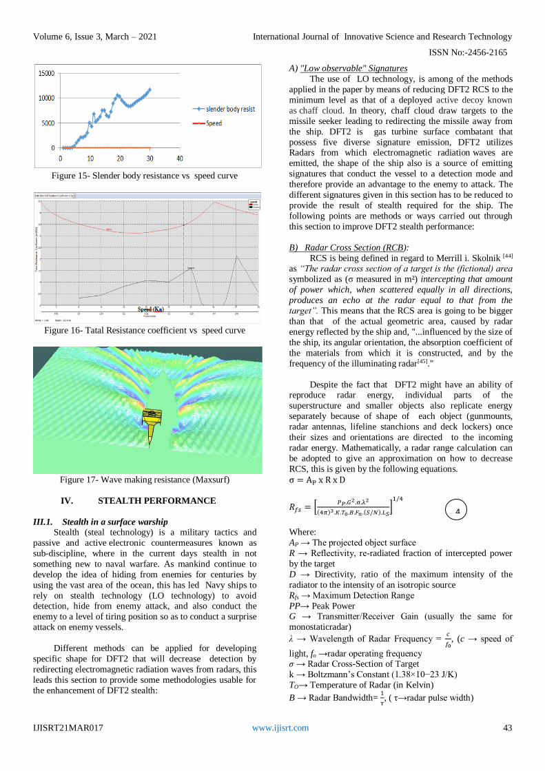
II.3.2. Computational analysis
In this part three computational tools will be kept in
consideration, 1) a tool for calculation wave resistance
characteristics. This will be carried out through the Maxsurf
software, from which a slender body analysis and hull
resistance curve as shown in the following figures. 2) a calculation of a boundary layer flow or a viscous flow
calculation providing a form factor variation results, 3) a
total resistance coefficient (Total free surface resistance
coefficient) calculation of the vessel highlighting the results
of the total resistance coefficient vs the ship speed, as Figure
16 demonstrates.
Figure 14- Slender body analysis and hull resistance curve
ū=c + u; v=v; w=w
1
2
3
1
3
Volume 6, Issue 3, March – 2021 International Journal of Innovative Science and Research Technology
ISSN No:-2456-2165
IJISRT21MAR017 www.ijisrt.com 43
Figure 15- Slender body resistance vs speed curve
Figure 16- Tatal Resistance coefficient vs speed curve
Figure 17- Wave making resistance (Maxsurf)
IV. STEALTH PERFORMANCE
III.1. Stealth in a surface warship
Stealth (steal technology) is a military tactics and
passive and active electronic countermeasures known as
sub-discipline, where in the current days stealth in not
something new to naval warfare. As mankind continue to
develop the idea of hiding from enemies for centuries by
using the vast area of the ocean, this has led Navy ships to
rely on stealth technology (LO technology) to avoid detection, hide from enemy attack, and also conduct the
enemy to a level of tiring position so as to conduct a surprise
attack on enemy vessels.
Different methods can be applied for developing
specific shape for DFT2 that will decrease detection by
redirecting electromagnetic radiation waves from radars, this
leads this section to provide some methodologies usable for
the enhancement of DFT2 stealth:
A) "Low observable" Signatures
The use of LO technology, is among of the methods
applied in the paper by means of reducing DFT2 RCS to the
minimum level as that of a deployed active decoy known
as chaff cloud. In theory, chaff cloud draw targets to the
missile seeker leading to redirecting the missile away from
the ship. DFT2 is gas turbine surface combatant that
possess five diverse signature emission, DFT2 utilizes Radars from which electromagnetic radiation waves are
emitted, the shape of the ship also is a source of emitting
signatures that conduct the vessel to a detection mode and
therefore provide an advantage to the enemy to attack. The
different signatures given in this section has to be reduced to
provide the result of stealth required for the ship. The
following points are methods or ways carried out through
this section to improve DFT2 stealth performance:
B) Radar Cross Section (RCB):
RCS is being defined in regard to Merrill i. Skolnik [44] as “The radar cross section of a target is the (fictional) area
symbolized as (σ measured in m²) intercepting that amount
of power which, when scattered equally in all directions,
produces an echo at the radar equal to that from the
target”. This means that the RCS area is going to be bigger
than that of the actual geometric area, caused by radar
energy reflected by the ship and, "...influenced by the size of
the ship, its angular orientation, the absorption coefficient of
the materials from which it is constructed, and by the
frequency of the illuminating radar[45]."
Despite the fact that DFT2 might have an ability of reproduce radar energy, individual parts of the
superstructure and smaller objects also replicate energy
separately because of shape of each object (gunmounts,
radar antennas, lifeline stanchions and deck lockers) once
their sizes and orientations are directed to the incoming
radar energy. Mathematically, a radar range calculation can
be adopted to give an approximation on how to decrease
RCS, this is given by the following equations.
σ = AP x R x D
𝑅𝑓𝑠 = [𝑃𝑃.𝐺2 .σ.λ2
(4𝜋)3.𝐾.𝑇0.𝐵.𝐹𝑛.(𝑆/𝑁).𝐿𝑆]
1/4
Where:
AP → The projected object surface
R → Reflectivity, re-radiated fraction of intercepted power
by the target
D → Directivity, ratio of the maximum intensity of the
radiator to the intensity of an isotropic source
Rfs → Maximum Detection Range
PP→ Peak Power G → Transmitter/Receiver Gain (usually the same for
monostaticradar)
λ → Wavelength of Radar Frequency = 𝑐
𝑓0, (c → speed of
light, fo →radar operating frequency σ → Radar Cross-Section of Target
k → Boltzmann’s Constant (1.38×10⁻²³ J/K)
TO→ Temperature of Radar (in Kelvin)
B → Radar Bandwidth= 1
𝜏, ( τ→radar pulse width)
4

Volume 6, Issue 3, March – 2021 International Journal of Innovative Science and Research Technology
ISSN No:-2456-2165
IJISRT21MAR017 www.ijisrt.com 44
F →Noise Figure of Radar Receiver
L → Radar Losses
S/N →Radar Threshold for Detection
The result of these equations provide an understanding
on how proportional the detection range(Rfs) of a radar can
be towards RCS of the target having a power of ¼ or σ¼. In
another word the range is proportional to the fourth root of
RCS. In symbols, 𝑅𝑎𝑛𝑔𝑒 = 𝑘 × √𝑅𝐶𝑆4
, where k is a
constant that depends on the radar and the situation[45]..
This gives as the ability to conclude on the reduction
of RCS, i.e. by reducing the RCS in 30000 times, the
detection range will be reduced to 30 times, hence DFT2
stealth enhancement on the reduction of the RCS is
possible. As a result the vessel can carry out its mission
without being discovered. To make this understandable an example is being conducted from (KoK and Steven Loke
Yew) is shown below[43].
Example:
An Electrical and Electronics Engineers (IEEE) C-band
radar with the following parameters:
Peak Power, PT = 1.5 MW
Antenna Gain, G = 45 dB
Operating Frequency, fo = 5.6GHz
Wavelength, 𝜆 =𝑐
𝑓0=
3×10⁸
5.6×109 =
0.053571 𝑚 Radar Temperature, To = 290K
Pulse Width, τ = 0.2 μs
Radar Band width, 𝐵 =1
𝜏=
1
0.2×10−6 =
5𝑀𝐻𝑧 RCS, σ = 100000 m2
Noise Figure, F = 3 dB
Radar Losses, L = 6 db
Radar Threshold Detection S/N = 20 dB
By utilizing the equation, and breaking the above
parameters and converting them in to dB unit, the equation
becomes:
(R4)dB = (PT + G2 + λ2+ σ – kToB – (4π)3 – F – S/N min)dB
The following table represent the calculating of each
individual parameters in dB:
Table 9- dB calculating results
PP G2
λ2 (4π)3 F kT
OB
S/N(S
/N)
KT
OB
σ
61.7
609
9
0
-
25.4213
-
136.9875
32.9
763
3 6 20 5
0
Equation gives the followings:
R4 = 61.7609 + 90 – 25.4213 + 50 + 136.9875 – 32.9763 – 3
– 6 – 20
= 251.3508 dB = 1.3648 × 1025 m4 (1)
R = √1.3648 × 10254= 1922.06 Km
By decreasing RCS up to 10dB or 10m2, (1) becomes:
R4 = 251.3508 - 10= 241.3508dB = 1.3648 × 10²¹
m4
→ 𝑅 = √1.3648 × 10²¹ 4
= 192.206 Km
DFT2 stealth will consider the use of Radiation-
absorbent material (RAM), which is a Radiation-absorbent
material, this will suck up (absorb) the emitted energy from
an enemy vessel or aircraft radar emitting into the coating
of the RAM and will change it to heat instead of reflected it
back. Figure 18 represent a radar absorbent material utilized
on a stealth bomber skin.
Figure18-B-2 bomber Skin (wikipedia)
2. Infra-red (IR): thermal radiation located in
electromagnetic range is able to IR signal, this signal is
emitted particularly in the Middle IR spectrum. "This
region corresponds to a heat source temperature between
500 and 1000 degrees Kelvin[5]. " The inlet and exhaust
gases releases high temperatures ranged at approximately
750 degrees Kelvin that emitting a radiation strongly in
the MIR region, therefore, the level of IR radiation in
that areas covers 2 percent of the ship's total surface and
can produce 99 percent of a total MIR of the ship signature. "It is important to note that it is these
concentrated MIR sources which serve to attract anti-
ship missiles with IR or dual mode (IR/radar) seekers."
Decrease and camouflage the concentrated heat in the
ship's machinery exhausts is primarily important for a
well enhanced stealth of DFT2.
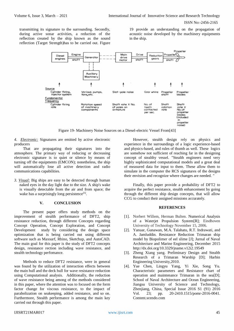
3. Acoustic: The creation of sound waves which can occur
internally or externally of the water have an ability to
travel through the water or the air, and might be collected
by a hydrophone which result to an acoustic noise. This
noise in is also known as an acoustic signature of the ship formed by a combination of all the sounds creation
from the machinery (i.e. machinery noise, propeller noise
"if in use", hydrodynamic noise, and if any, the ship’s
sonar noise, and so on). DFT2 acoustic signature can be
decreased by utilizing or adopting the following methods
in two areas. At first, the passive sonar detection can be
reduced as the ship can ship generate noise in a certain
level that should be lowered or masked from
4
5
5
Volume 6, Issue 3, March – 2021 International Journal of Innovative Science and Research Technology
ISSN No:-2456-2165
IJISRT21MAR017 www.ijisrt.com 45
transmitting its signature to the surrounding. Secondly,
during active sonar activities, a reduction of the
reflection created by the ship known as the sound
reflection (Target Strength)has to be carried out. Figure
19 provide an understanding on the propagation of
acoustic noise developed by the machinery equipments
in the ship.
Figure 19- Machinery Noise Sources on a Diesel-electric Vessel From[43]
4. Electronic: Signatures are emitted by active electronic
producers
That are propagating their signatures into the
atmosphere. The primary way of reducing or decreasing electronic signature is to quiet or silence by means of
turning off the equipments (EMCON); nonetheless, the ship
will automatically lose all active detection and radio
communications capabilities.
3. Visual: Big ships are easy to be detected through human
naked eyes in the day light due to the size. A ship's wake
is visually detectable from the air and from space; the
wake has a surprisingly long persistence[5].
V. CONCLUSION
The present paper offers study methods on the
improvement of stealth performance of DFT2, ship
resistance reduction, through different Concepts regarding
Concept Operation, Concept Exploration, and Concept
Development study by considering the design space
optimization that is being carried out using different
software such as Maxsurf, Rhino, Sketchup, and AutoCAD.
The main goal for this paper is the study of DFT2 concepts
design, resistance rection including wave resistance, and
stealth technology perfomance.
Methods to reduce DFT2 resistance, were in general
was found by the utilization of interaction effects between
the main hull and the deck hull for wave resistance reduction
using Computational analysis. Additionally, the reduction
of wave resistance being among of the methods considered
in this paper, where the attention was to focused on the form
factor change for viscous resistance, to the impact of
parabolization on seakeeping, added resistance, and so on.
Furthermore, Stealth performance is among the main key
carried out through this paper.
However, stealth design rely on physics and
experience in the surroundings of a logic experience-based
and physics-based, and rules of thumb as well. These logics
are somehow not sufficient of reaching far in the designing concept of stealthy vessel. "Stealth engineers need very
highly sophisticated computational models and a great deal
of measured data for input to them. These allow them to
simulate in the computer the RCS signatures of the designs
their envision and recognize where changes are needed. "
Finally, this paper provide a probability of DFT2 to
acquire the perfect resistance, stealth enhancement by going
through the different ship design concepts, that will allow
CCG to conduct their assigned missions accurately.
REFERENCES
[1]. Norbert Willem, Herman Bulten. Numerical Analysis
of a Waterjet Propulsion System[R]; Eindhoven
University of Technology November 15, 2006.
[2]. Yanuar, Gunawan, M.A. Talahatu, R.T. Indrawati, and
A. Jamluddin. Resistance Reduction Trimaran ship
model by Biopolimer of eel slime [J]; Jurnal of Naval
Architecture and Marine Engineering, December 2015
http://dx.doi.org/10.3329/jname.v12i2.19549
[3]. Zheng Xiang yang. Preliminary Design and Stealth
Research of a Trimaran Warship [D]; Harbin Engineering University,2010.
[4]. Yue Chen, Lingyu Yang, Yi Xie, Song Yu.
Characteristic parameters and Resistance chart of
operation and maintenance Trimaran in the sea[D];
School of Naval Architecture and Ocean Engineering,
Jiangsu University of Science and Technology,
Zhenjiang, China, Special Issue 2016 S1 (91) 2016
Vol. 23; pp. 20-2410.1515/pomr-2016-0041.
Content.scendo.com
Volume 6, Issue 3, March – 2021 International Journal of Innovative Science and Research Technology
ISSN No:-2456-2165
IJISRT21MAR017 www.ijisrt.com 46
[5]. John W. Mc Gillvray, Jr. Commander, U.S. Navy.
Stealth Technology in Surface Warships; How This
Concept Affects the Execution of the Maritime
Strategy[R]; Naval war college Newport, R.I. May 18
1992.
[6]. LT Justin Strock and Dr. Alan Brown. Methods for
Naval Ship Concept and Propulsion Technology
Exploration in a CGX Case Study [D]; Virginia Tech University.
[7]. Mohamed SAID, FANB Bin. Design Study of
Trimaran Frigate DFT[D]; Department of Engineering,
Naval University of Engineering, Wuhan, Hubei,
430033, China, January 2021.
https://ijisrt.com/design-study-of-trimaran-frigate-dft
[8]. Dr. Alan Brown and LT Corey Kerns. Multi-Objective
Optimization in Naval Ship Concept Design [D];
Offshore Patrol Vessel (OPV) Virginia Tech
University. https://www.phoenix-int.com
[9]. E.C. Tupper, BSc, CEng, RCNC, FRINA, WhSch. Introduction to Naval Architecuture [M]; Britishlibrary
Cataloguing in publication data, 1996.
https://www.homepags.ed.ac.uk
[10]. David Cash, Gerritt Lang, Dorothy Mc Dowell, Cory
Mc Graw, Scott Patter, and Joshua Staubs. Concept
exploration and Development of an Agile Surface
Combat (ACS) [R]; trimaran ASC HI-2 Ocean
Engineering Design Report AOE4065/4066 Virginia
Tech University, Fall 2003-Spring 2004.
www.dept.aoe. vt.edu
[11]. Morgan Baldwin , Aaron Cox , Nathan Good , Nick
Marickovich , Travis Smith , and Ryan Webster. Concept exploration and Development of an Advanced
Logistics Delivery Ship (ALDV) [R]; ALDV HI-2
Ocean Engineering Design Report AOE4065/4066
Virginia Tech University, ,Fall 2004 – Spring 2005.
[12]. Jang Young-sung. Ship Resistance Calculation and
Trimaran Layout Optimization [D]; Tianjin
University,2012.
[13]. Bayartu. Design and Construction of Naval
Architecture and Ocean Structure [D]; Harbin
University of Engineering, June 2013.
[14]. Panagiodis Dimitroglu. Performance of high speed multi-hull ship [R]; Massachusetts Institute of
Technology, June 1998.
[15]. Next generation axial flow waterjet
https://www.kongsberg.com/contentassets
[16]. 300/400 series trifold brochure low res compressed
https://www.thrustmaster.net
[17]. Course Objectives chapter 2.2, Hull form and
geometry [M]. Naval Accademy.
https://www.usna.edu
[18]. Owen F. Hughes and Jeom Kee Paik with Dominique
Béghin, John B. Caldwell, Hans G. Payer and Thomas
E. Schellin. Ship structural analysis and design [M]. The Society of Naval Architects and Marine Engineers
601 Pavonia Avenue Jersey City, New Jersey 07306,
2010. https://www.toaz.info
[19]. Ngo Van He1, Keisuke Mizutani2, and Yoshiho Ikeda3.
Reducing air resistance acting on a ship by using
interactio n effects between the hull and
accommodation[D]; 1School of Transportation
Engineering, Hanoi University of Science and
Technology, Hanoi, Vietnam, 2Sanoyas Shipbuilding
Corporation, Osaka, Osaka, Japan, 3Osaka Prefecture
University, Osaka, Japan, December 2014. [20]. Dr. Michael Parsons, Dr. Hyun Chung, Dr. Eleanor
Nick,Anthony Daniels, Su Liu, Dr. Jignesh Patel.
Intelligent Ship Arrangements (ISA): a New Approach
to General Arrangement [J]; Naval Engineers Journal,
Vol. 120, No. 3, 2008, pp. 51-65.
[21]. Marine Engine IMO Tier II and Tier III, Programme
2015. https://www.marine.mandieselturbo.com
[22]. J. Albers. MAN B&W medium-speed engines - the
right propulsion system for the merchant ship types.
MAN B&W Diesel AG, D-86135 Augsburg,
Germany,February1893. https://www.witpress.com [23]. R. W. SAATY. Analytical Hierarchy Process (AHP,
Saaty 1996) [J]; Mathld Modelling, Vol. 9, No. 3-5,
pp. 161-176, 1987 Printed in Great Britain Pergamon
Journals Ltd,1987. https://core.ac.uk
[24]. Han Bingbing. Keywords SWath ship form design and
resistance performance research [D]; Dalian University
of Technology, 2019.
[25]. James Schultz, Justin Baity, Erika Kast, John Wilde,
Nate Reimold, Rich Hardy. Concept Exploration and
Development of an Air Superiority Cruiser CG(X) [R];
CGX Variant1 Ocean Engineering Design Project
AOE 4065/4066, Fall 2005 – Spring 2006. [26]. Ang Li, Yunbo Li. Numerical and experimental study
on seakeeping Performance of a high speed trimaran
with t-foil in Head waves[R]; Polish maritime
research 3 (103) 2019 vol. 26; pp. 65-77
10.2478/pomr-2019-0047
[27]. Devrim Bülent Danışman1*, Ömer Gören1 and Sander
Çalışal2. Resistance Reduction Studies by Means of
Increasing the Beam with Waterline Parabolization[D];
1 Department of Naval Architecture and Marine
Engineering, Faculty of Naval Architecture and Ocean
Engineering, Istanbul Technical University, Istanbul, Turkey, 2University of British Columbia, Vancouver,
Canada and Piri Reis University, Istanbul, Turkey,
March 2017.
[28]. Omar bin Yaakob. Ship hydrostatics and stability: A
systematic approach[M]; University of Technology
Malaysia, August 2012.
[29]. https://en.wikipedia.org/wiki/Stealth_ship
[30]. Samuel F. Kilceski. Department of Generalized
Trimaran Hull form Design Method of Naval Warship
[R]; Faculty of the University of New Orleans, May
2014.
[31]. Xinyu LIANG, Yali XUE, Zheng LI. Techno-economic analysis of applying China’s R0110 gas
turbine in IGCC plants[D]; Department of Thermal
Engineering, Tsinghua University State Key Lab of
Power Systems Beijing, China, May 2011.

Volume 6, Issue 3, March – 2021 International Journal of Innovative Science and Research Technology
ISSN No:-2456-2165
IJISRT21MAR017 www.ijisrt.com 47
[32]. Yue Chen, Lingyu Yang¸Yi Xie¸Song Yu. The
research on characteristic parameters and Resistance
chart of operation and maintenance Trimaran in the
sea[D]; School of Naval Architecture and Ocean
Engineering, Jiangsu University of Science and
Technology, Zhenjiang, China, Polish Maritime
Research Special Issue 2016 S1 (91) 2016 Vol. 23; pp.
20-24 10.1515/pomr-2016-004. [33]. Swaroop N. Neti. Ship design optimization using asset
[R]; Virginia Polytechnic Institute and State
University, Blacksburg, Virginia, February 10, 2005.
www.dept.aoe. vt.edu
[34]. https://www.mermaid-consultants.com/ship-resistance-
calculation.html
[35]. James S. Webster, Howard Fireman, Dillon A. Allen,
Adrian J. Mackenna, John C. Hootman. Alternative
Propulsion Methods for Surface Combatants and
Amphibious Warfare Ships[D].
http://doerry.org/norbert/references/AlternatePropulsionStudy-ApprovedforPublicRelease03-21-07.pdf
[36]. Deng Bo,Zhang Er, Zhang Zhenhua, Mei Ziyuan (ship
structure and intensity foundation) Warship Structure
and Strength Basics [D];Naval University of
engineering Press, March 2019.
[37]. Finn C. Michelsen. Wave resistance solution of
Michell's integral for polynomial ship forms [R]; the
University of Michigan Industry Program of the
College of Engineering, July 1906.
[38]. Ismail Kilicaslan. Manpower systems integration
factors for Frigate design in the turkish navy [R];
Naval Postgraduate School Monterey (NPS), California, December 2016. From: apps.dtic.mil
[39]. Maggy. Design and Manufacture of ships and Marine
Structures [D]; Shanghai Institute of Ships and Marine
Engineering, March 2011.
[40]. Sarah E. Rollings. Seakeeping analysis of small
displacement high-speed vessels[R]; Naval
Postgraduate School (NPS) monterey, california,
March 2003.
[41]. Kennell, Colen. “Design Trends in High-Speed
Transport” [D]; Marine Technology, Vol. 35, No. 3,
pp. 127-134, July 1998. [42]. William D. O’Neil. Stealth Radar stealth[D]; US
Institute for Defense Analyses, published in 2001.
analysis.williamdoneil.com
[43]. Kok, Steven Loke Yew. Naval Survivability and
Susceptibility Reduction StudySurface Ship[R];
Monterey, California. Naval Postgraduate School
(NPS), 2012-09. http://hdl.handle.net/10945/17404
[44]. Merrill i. Skolnik. Introduction to Radar
Systems(Second edition) [M]; Mcgraw-hill Book
Company, international edition 198.
http://s2.bitdownload.ir/Ebook/Electronics/Skolnik%2
0%20Introduction%20to%20Radar%20Systems%203e%20IE%20(McGraw,%201981).pdf
[45]. Ingo Harre, Bremen, Germany. RCS in Radar Range
Calculations for Maritime Targets[D]; V2.0-20040206.
http://www.mar-it.de/Radar/RCS/RCS_xx.pdf