Embed Size (px)
Citation preview

Shorten the road to done.
Autodesk®
InventorRouted Systems
Autodesk®
Inventor®
Routed Systems
2
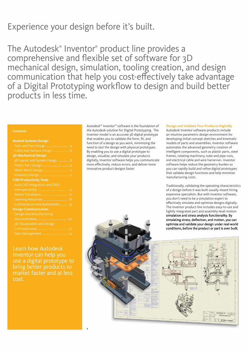
The Autodesk® Inventor® product line provides a comprehensive and flexible set of software for 3D mechanical design, simulation, tooling creation, and design communication that help you cost-effectively take advantage of a Digital Prototyping workflow to design and build better products in less time.
Experience your design before it’s built.
Autodesk® Inventor® software is the foundation of the Autodesk solution for Digital Prototyping. TheInventor model is an accurate 3D digital prototype that enables you to validate the form, fit, andfunction of a design as you work, minimizing the need to test the design with physical prototypes. By enabling you to use a digital prototype to design, visualize, and simulate your productsdigitally, Inventor software helps you communicate more effectively, reduce errors, and deliver moreinnovative product designs faster.
Design and Validate Your Products Digitally Autodesk Inventor software products includean intuitive parametric design environment fordeveloping initial concept sketches and kinematicmodels of parts and assemblies. Inventor softwareautomates the advanced geometry creation of intelligent components, such as plastic parts, steelframes, rotating machinery, tube and pipe runs,and electrical cable and wire harnesses. Inventor software helps reduce the geometry burden soyou can rapidly build and refine digital prototypes that validate design functions and help minimize manufacturing costs.
Traditionally, validating the operating characteristicsof a design before it was built usually meant hiringexpensive specialists. But with Inventor software, you don’t need to be a simulation expert toeffectively simulate and optimize designs digitally. The Inventor product line includes easy-to-use and tightly integrated part and assembly-level motion
Contents
Routed Systems Design Tube and Pipe Design ............................ 4 Cable and Harness Design ..................... 63D Mechanical Design 3D Layout and System Design .............. 8 Plastic Part Design.................................... 9 Sheet Metal Design ................................ 11 Assembly Design .................................... 13CAD Productivity Tools AutoCAD Integration and DWG Interoperability ...................................... 15 Native Translators .................................. 17 Learning Resources ................................ 18 Customization and Automation .......... 19Design Communication Design and Manufacturing Documentation ...................................... 20 3D Visualization and Design Communication ..................................... 22 Data Management................................. 24
Learn how Autodesk Inventor can help you use a digital prototype to bring better products to market faster and at less cost.
3
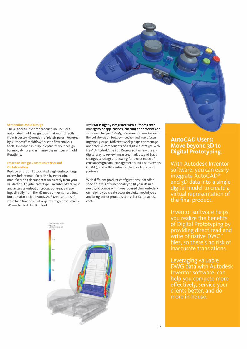
Streamline Mold Design The Autodesk Inventor product line includes automated mold design tools that work directlyfrom Inventor 3D models of plastic parts. Powered by Autodesk® Moldflow® plastic flow analysis tools, Inventor can help to optimize your design for moldability and minimize the number of mold iterations.
Improve Design Communication and Collaboration Reduce errors and associated engineering changeorders before manufacturing by generating manufacturing documentation directly from yourvalidated 3D digital prototype. Inventor offers rapidand accurate output of production-ready draw-ings directly from the 3D model. Inventor productbundles also include AutoCAD® Mechanical soft-ware for situations that require a high-productivity 2D mechanical drafting tool.
Invenmanasecure exchange of design data and promoting ear-lier collaboration between design and manufactur-ing workgroups. Different workgroups can manage and track all components of a digital prototype with free* Autodesk® Design Review software—the all-digital way to review, measure, mark up, and track changes to designs—allowing for better reuse of crucial design data, management of bills of materials(BOMs), and collaboration with other teams andpartners.
With different product configurations that offerspecific levels of functionality to fit your designneeds, no company is more focused than Autodeskon helping you create accurate digital prototypesand bring better products to market faster at lesscost.
AutoCAD Users: Move beyond 3D to Digital Prototyping.
With Autodesk Inventor software, you can easily integrate AutoCAD®
and 3D data into a single digital model to create a virtual representation of the final product.
Inventor software helps you realize the benefits of Digital Prototyping by providing direct read and write of native DWG™
files, so there’s no risk of inaccurate translations.
Leveraging valuable DWG data with Autodesk Inventor software can help you compete more effectively, service your clients better, and do more in-house.

4
Use Autodesk® Inventor® Routed Systems software to accelerate the design for routed elements, including tubing, piping, and flexible hose.
Tube and Pipe Design
Functional Route DesignSimplify the design of pipe runs—or spools—to fit in complex assemblies or tight spaces. Automatically routed segments respect predefined routing styles to present you with alternative pipe routes that comply with routing rules, such as minimum or maximum length criteria and bend radius. You can also define pipe runs manually by creating 3D sketch geometry or build them up interactively using the route edit tools. For maximum control, combine automatically routed segments with user-defined segments.
Pipe Fittings Library Improve quality, easily organize parts, and eliminate tedious searching with automatic placement of the correct part from an extensive library of piping components. The library contains commonly used, industry-standard tubing, piping, hose, and fittings, including ANSI, DIN, ISO, and JIS. Add or modify properties, including part numbers, to existing parts and control file names used to instance fittings, pipes, tubes, and other content.
Changing to different styles of fittings is quick and easy. Simply select a different pipe style and Autodesk Inventor repopulates the pipe run with the new fittings while adhering to any new design rules.
Flexible HoseMake sure flexible hose and fittings fit properly using a 3D digital prototype that drives accurate manufacturing documentation. The system inserts appropriate hose fittings from the Content Center and checks for minimum bend radius based on the hose style you select. Hose lengths are updated automatically for use in Length Roll-Up commands.
5
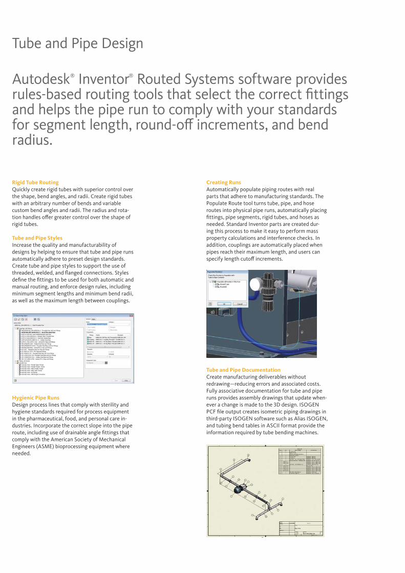
Rigid Tube RoutingQuickly create rigid tubes with superior control over the shape, bend angles, and radii. Create rigid tubes with an arbitrary number of bends and variable custom bend angles and radii. The radius and rota-tion handles offer greater control over the shape of rigid tubes.
Tube and Pipe StylesIncrease the quality and manufacturability of designs by helping to ensure that tube and pipe runs automatically adhere to preset design standards. Create tube and pipe styles to support the use of threaded, welded, and flanged connections. Styles define the fittings to be used for both automatic and manual routing, and enforce design rules, including minimum segment lengths and minimum bend radii, as well as the maximum length between couplings.
Hygienic Pipe RunsDesign process lines that comply with sterility and hygiene standards required for process equipment in the pharmaceutical, food, and personal care in-dustries. Incorporate the correct slope into the pipe route, including use of drainable angle fittings that comply with the American Society of Mechanical Engineers (ASME) bioprocessing equipment where needed.
Creating RunsAutomatically populate piping routes with real parts that adhere to manufacturing standards. The Populate Route tool turns tube, pipe, and hose routes into physical pipe runs, automatically placing fittings, pipe segments, rigid tubes, and hoses as needed. Standard Inventor parts are created dur-ing this process to make it easy to perform mass property calculations and interference checks. In addition, couplings are automatically placed when pipes reach their maximum length, and users can specify length cutoff increments.
Tube and Pipe DocumentationCreate manufacturing deliverables without redrawing—reducing errors and associated costs. Fully associative documentation for tube and pipe runs provides assembly drawings that update when-ever a change is made to the 3D design. ISOGEN PCF file output creates isometric piping drawings in third-party ISOGEN software such as Alias ISOGEN, and tubing bend tables in ASCII format provide the information required by tube bending machines.
Tube and Pipe Design
Autodesk® Inventor® Routed Systems software provides rules-based routing tools that select the correct fittings and helps the pipe run to comply with your standards for segment length, round-off increments, and bend radius.
6
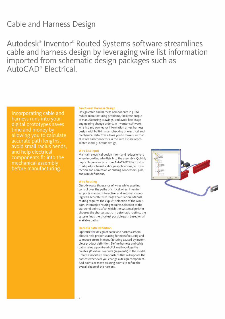
Autodesk® Inventor® Routed Systems software streamlines cable and harness design by leveraging wire list information imported from schematic design packages such as AutoCAD® Electrical.
Cable and Harness Design
Functional Harness DesignDesign cable and harness components in 3D to reduce manufacturing problems, facilitate output of manufacturing drawings, and avoid late-stage engineering change orders. In Inventor software, wire list and connector information drives harness design with built-in cross-checking of electrical and mechanical data. This allows you to make sure that all wires and connectors in the wire list are repre-sented in the 3D cable design.
Wire List InputMaintain electrical design intent and reduce errors when importing wire lists into the assembly. Quickly import large wire lists from AutoCAD® Electrical or third-party schematic design applications, with de-tection and correction of missing connectors, pins, and wire definitions.
Wire RoutingQuickly route thousands of wires while exerting control over the paths of critical wires. Inventor supports manual, interactive, and automatic rout-ing with accurate wire length calculation. Manual routing requires the explicit selection of the wire’s path. Interactive routing requires selection of the start/end points, after which the system algorithm chooses the shortest path. In automatic routing, the system finds the shortest possible path based on all available paths.
Harness Path Definition Optimize the design of cable and harness assem-blies to help proper spacing for manufacturing and to reduce errors in manufacturing caused by incom-plete product definition. Define harness and cable paths using a point-and-click methodology that creates 3D virtual conduits (segments) in the model. Create associative relationships that will update the harness whenever you change a design component. Add points or move existing points to refine the overall shape of the harness.
Incorporating cable and harness runs into your digital prototypes saves time and money by allowing you to calculate accurate path lengths, avoid small radius bends, and help electrical components fit into the mechanical assembly before manufacturing.
7
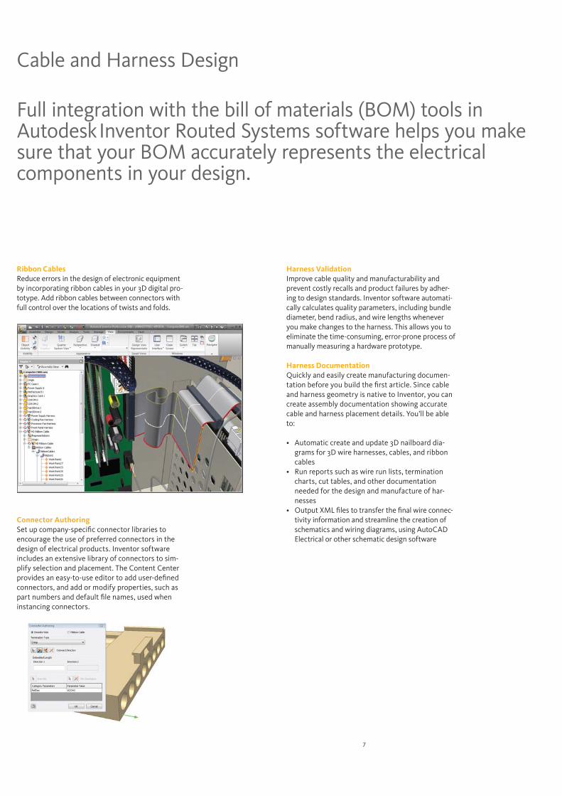
Harness ValidationImprove cable quality and manufacturability and prevent costly recalls and product failures by adher-ing to design standards. Inventor software automati-cally calculates quality parameters, including bundle diameter, bend radius, and wire lengths whenever you make changes to the harness. This allows you to eliminate the time-consuming, error-prone process of manually measuring a hardware prototype.
Harness DocumentationQuickly and easily create manufacturing documen-tation before you build the first article. Since cable and harness geometry is native to Inventor, you can create assembly documentation showing accurate cable and harness placement details. You’ll be able to:
-grams for 3D wire harnesses, cables, and ribbon cables
charts, cut tables, and other documentation needed for the design and manufacture of har-nesses
-tivity information and streamline the creation of schematics and wiring diagrams, using AutoCAD Electrical or other schematic design software
Ribbon CablesReduce errors in the design of electronic equipment by incorporating ribbon cables in your 3D digital pro-totype. Add ribbon cables between connectors with full control over the locations of twists and folds.
Connector AuthoringSet up company-specific connector libraries to encourage the use of preferred connectors in the design of electrical products. Inventor software includes an extensive library of connectors to sim-plify selection and placement. The Content Center provides an easy-to-use editor to add user-defined connectors, and add or modify properties, such as part numbers and default file names, used when instancing connectors.
Cable and Harness Design
Full integration with the bill of materials (BOM) tools in AutodeskInventor Routed Systems software helps you make sure that your BOM accurately represents the electrical components in your design.
8
Getting the initial design concept right is the key to a successful project. Move your initial design studies from paper by using the parametric design environment in Inventor to develop initial concept sketches and kinematic models.
3D Layout and System Design
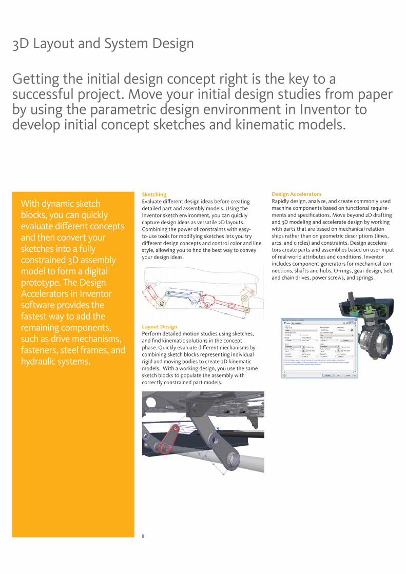
SketchingEvaluate different design ideas before creating detailed part and assembly models. Using the Inventor sketch environment, you can quickly capture design ideas as versatile 2D layouts. Combining the power of constraints with easy-to-use tools for modifying sketches lets you try different design concepts and control color and line style, allowing you to find the best way to convey your design ideas.
Layout Design Perform detailed motion studies using sketches, and find kinematic solutions in the concept phase. Quickly evaluate different mechanisms by combining sketch blocks representing individual rigid and moving bodies to create 2D kinematic models. With a working design, you use the same sketch blocks to populate the assembly with correctly constrained part models.
With dynamic sketch blocks, you can quickly evaluate different concepts and then convert your sketches into a fully constrained 3D assembly model to form a digital prototype. The Design Accelerators in Inventor software provides the fastest way to add the remaining components, such as drive mechanisms, fasteners, steel frames, and hydraulic systems.
Design AcceleratorsRapidly design, analyze, and create commonly used machine components based on functional require-ments and specifications. Move beyond 2D drafting and 3D modeling and accelerate design by working with parts that are based on mechanical relation-ships rather than on geometric descriptions (lines, arcs, and circles) and constraints. Design accelera-tors create parts and assemblies based on user input of real-world attributes and conditions. Inventor includes component generators for mechanical con-nections, shafts and hubs, O-rings, gear design, belt and chain drives, power screws, and springs.
9
Autodesk® Inventor® software offers plastic parts designers maximum flexibility by combining native Inventor geometry with exterior surface models designed with industrial design applications such as the Autodesk® Alias family of products.
Plastic Part Design
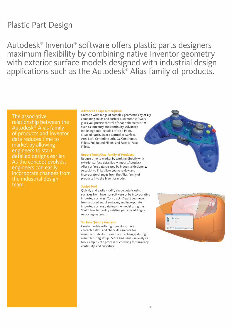
Advanced Shape DescriptionCreate a wide range of complex geometries by combining solids and surfaces. Inventor softwagives you precise control of shape characteristisuch as tangency and continuity. Advancedmodeling tools include Loft to a Point, N-Sided Patch, Sweep Normal to Surface,Area Loft, Centerline Loft, G2 ContinuousFillets, Full Round Fillets, and Face-to-FaceFillets.
Import from Alias Family of ProductsReduce time to market by working directly withexterior surface data. Easily import Autodesk Alias surface data created by industrial designeAssociative links allow you to review and incorporate changes from the Alias family of products into the Inventor model.
Sculpt ToolQuickly and easily modify shape details using surfaces from Inventor software or by incorporatingimported surfaces. Construct 3D part geometry from a closed set of surfaces, and incorporate imported surface data into the model using the Sculpt tool to modify existing parts by adding or removing material.
Surface Quality AnalysisCreate models with high-quality surfacecharacteristics, and check design data formanufacturability to avoid costly changes duringmanufacturing setup. Zebra and Gaussian analysistools simplify the process of checking for tangency,continuity, and curvature.
The associative relationship between the Autodesk® Alias family of products and Inventor data reduces time to market by allowing engineers to start detailed designs earlier. As the concept evolves, engineers can easily incorporate changes from the industrial design team.
10
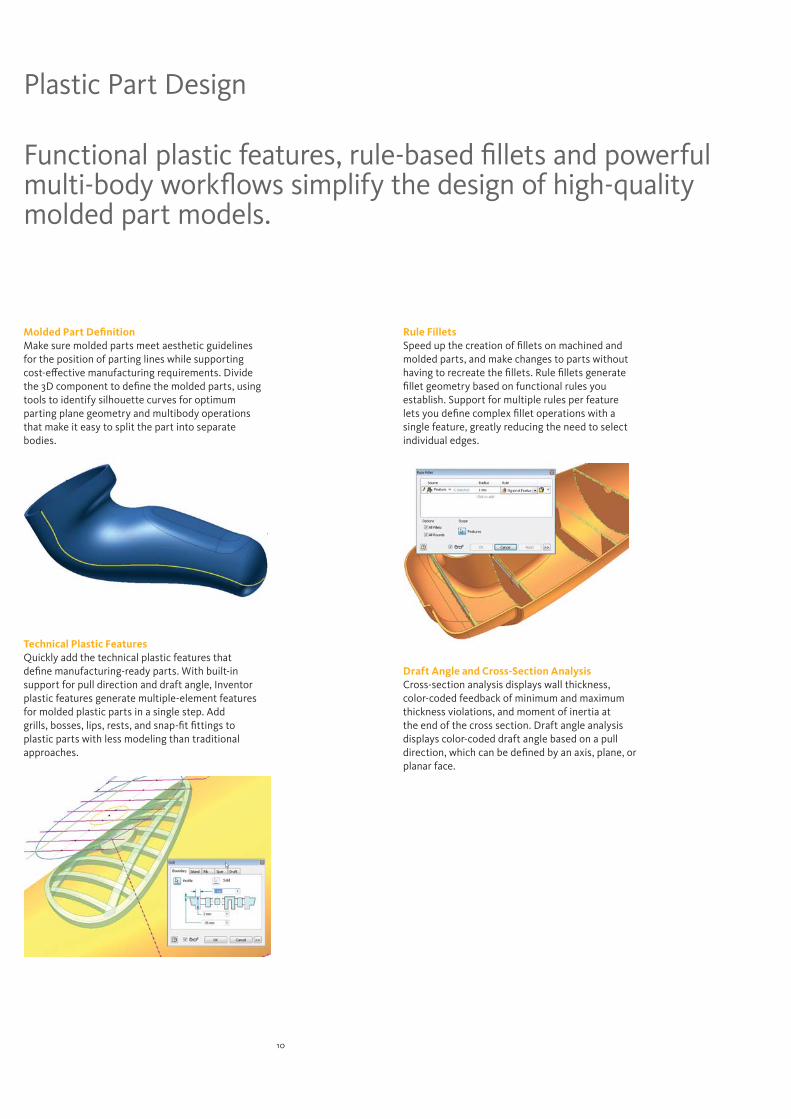
Molded Part Definition Make sure molded parts meet aesthetic guidelines for the position of parting lines while supporting cost-effective manufacturing requirements. Divide the 3D component to define the molded parts, using tools to identify silhouette curves for optimum parting plane geometry and multibody operations that make it easy to split the part into separate bodies.
Technical Plastic FeaturesQuickly add the technical plastic features that define manufacturing-ready parts. With built-in support for pull direction and draft angle, Inventor plastic features generate multiple-element features for molded plastic parts in a single step. Add grills, bosses, lips, rests, and snap-fit fittings to plastic parts with less modeling than traditional approaches.
Rule FilletsSpeed up the creation of fillets on machined and molded parts, and make changes to parts without having to recreate the fillets. Rule fillets generate fillet geometry based on functional rules you establish. Support for multiple rules per feature lets you define complex fillet operations with a single feature, greatly reducing the need to select individual edges.
Draft Angle and Cross-Section AnalysisCross-section analysis displays wall thickness, color-coded feedback of minimum and maximum thickness violations, and moment of inertia at the end of the cross section. Draft angle analysis displays color-coded draft angle based on a pull direction, which can be defined by an axis, plane, or planar face.
Plastic Part Design
Functional plastic features, rule-based fillets and powerful multi-body workflows simplify the design of high-quality molded part models.

11
Use the Inventor Digital Prototype to simplify the design of complex sheet metal parts.
Sheet Metal Design
Sheet Metal StylesGenerate flat patterns that accurately reflect your manufacturing capabilities. Control sheet metal unfolding with styles that define the material thickness, bend rules, and corner reliefs. To control the unfolding geometry, Inventor software supports linear unfolding, custom unfold equations, and custom bend tables.
Sheet Metal FlangesSpeed up the design of sheet metal parts with complex flanges using intelligent 3D models that take your manufacturing processes into account. Intelligent features enable the creation of multiple flanges in a single operation with rich unfold options, automatic mitering, and seam level overrides for precise control of overlap and relief conditions. Supported features include flanges, contour flanges, and lofted flanges.
Roll-Formed PartsCreate accurate digital prototypes that include roll-formed parts. The contour roll command simplifies the creation of rolled features with full support for supplemental sheet metal features and flat-pattern operations.
Autodesk Inventor software improves your productivity when you design sheet metal parts by providing a digital prototype that combines manufacturing information – such as punch tool parameters and custom bend tables – with an accurate, 3D model of sheet metal folding and a flat-pattern editing environment where manufacturing engineers can tweak flat patterns to minimize manufacturing costs.
Transitional ShapesEfficiently design parts for ducting, material handling hoppers, exhaust hoods, and other uses that require press-brake or die-form techniques. The lofted flange and rip features simplify the design of transitional shapes with options to create geometry for both die-form operations and press brakes.
Unfold Design WorkflowsSimplify the inclusion of punches, cuts, fillets, chamfers, and extrusions that span sheet metal bend plates. Use the unfold and refold commands to create features using an unfolded representation of the part. Automatically propagate the resulting features to both the folded model and the flat pattern.
12
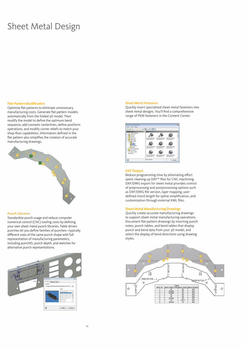
Flat-Pattern ModificationOptimize flat patterns to eliminate unnecessary manufacturing costs. Generate flat-pattern models automatically from the folded 3D model. Then modify the model to define the optimum bend sequence, add cosmetic centerlines, define postform operations, and modify corner reliefs to match your shop-floor capabilities. Information defined in the flat pattern also simplifies the creation of accurate manufacturing drawings.
Punch LibrariesStandardize punch usage and reduce computer numerical control (CNC) tooling costs by defining your own sheet metal punch libraries. Table-driven punches let you define families of punches—typically different sizes of the same punch shape with full representation of manufacturing parameters, including punchID, punch depth, and sketches for alternative punch representations.
Sheet Metal FastenersQuickly insert specialized sheet metal fasteners into sheet metal designs. You’ll find a comprehensive range of PEM fasteners in the Content Center.
DXF OutputReduce programming time by eliminating effort spent cleaning up DXF™ files for CNC machining. DXF/DWG export for sheet metal provides control of preprocessing and postprocessing options such as DXF/DWG file version, layer mapping, user-defined chord length for spline simplification, and customization through external XML files.
Sheet Metal Manufacturing DrawingsQuickly create accurate manufacturing drawings to support sheet metal manufacturing operations. Document flat-pattern drawings by inserting punch notes, punch tables, and bend tables that display punch and bend data from your 3D model, and select the display of bend directions using drawing styles.
Sheet Metal Design
13
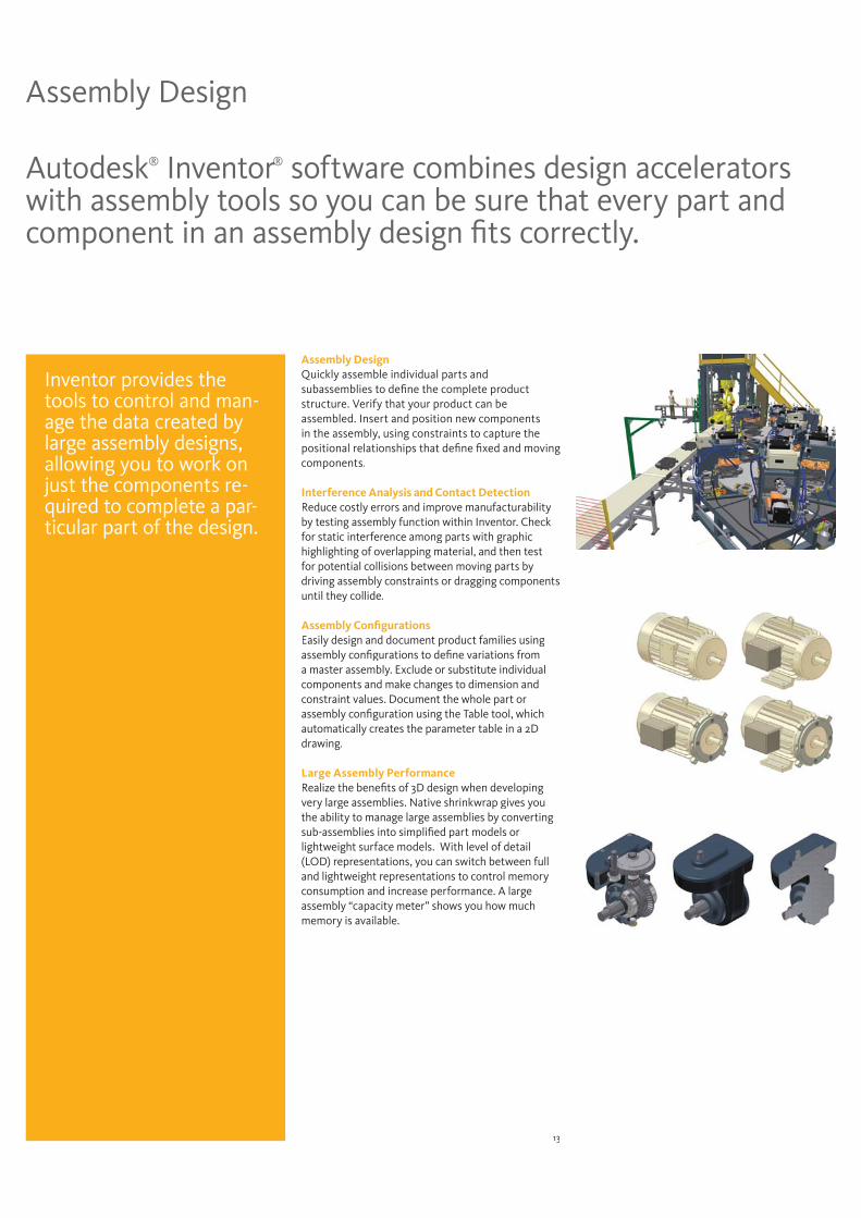
Assembly DesignQuickly assemble individual parts and subassemblies to define the complete product structure. Verify that your product can beassembled. Insert and position new components in the assembly, using constraints to capture the positional relationships that define fixed and moving components.
Interference Analysis and Contact DetectionReduce costly errors and improve manufacturabilityby testing assembly function within Inventor. Check for static interference among parts with graphic highlighting of overlapping material, and then test for potential collisions between moving parts bydriving assembly constraints or dragging componentsuntil they collide.
Assembly Configurations Easily design and document product families using assembly configurations to define variations froma master assembly. Exclude or substitute individual components and make changes to dimension andconstraint values. Document the whole part orassembly configuration using the Table tool, which automatically creates the parameter table in a 2D drawing.
Large Assembly Performance Realize the benefits of 3D design when developing very large assemblies. Native shrinkwrap gives youthe ability to manage large assemblies by converting sub-assemblies into simplified part models orlightweight surface models. With level of detail(LOD) representations, you can switch between full and lightweight representations to control memoryconsumption and increase performance. A largeassembly “capacity meter” shows you how muchmemory is available.
Assembly Design
Autodesk® Inventor® software combines design accelerators with assembly tools so you can be sure that every part and component in an assembly design fits correctly.
Inventor provides the tools to control and man-age the data created by large assembly designs, allowing you to work on just the components re-quired to complete a par-ticular part of the design.
14
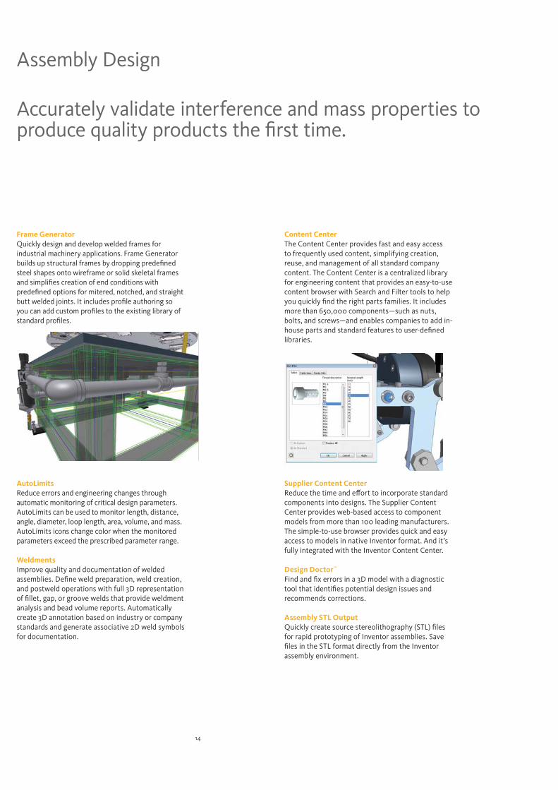
Frame GeneratorQuickly design and develop welded frames for industrial machinery applications. Frame Generator builds up structural frames by dropping predefined steel shapes onto wireframe or solid skeletal frames and simplifies creation of end conditions with predefined options for mitered, notched, and straight butt welded joints. It includes profile authoring so you can add custom profiles to the existing library of standard profiles.
AutoLimitsReduce errors and engineering changes through automatic monitoring of critical design parameters. AutoLimits can be used to monitor length, distance, angle, diameter, loop length, area, volume, and mass. AutoLimits icons change color when the monitored parameters exceed the prescribed parameter range.
Weldments Improve quality and documentation of welded assemblies. Define weld preparation, weld creation, and postweld operations with full 3D representation of fillet, gap, or groove welds that provide weldment analysis and bead volume reports. Automatically create 3D annotation based on industry or company standards and generate associative 2D weld symbols for documentation.
Content Center The Content Center provides fast and easy access to frequently used content, simplifying creation, reuse, and management of all standard company content. The Content Center is a centralized library for engineering content that provides an easy-to-use content browser with Search and Filter tools to help you quickly find the right parts families. It includes more than 650,000 components—such as nuts, bolts, and screws—and enables companies to add in-house parts and standard features to user-defined libraries.
Supplier Content Center Reduce the time and effort to incorporate standard components into designs. The Supplier Content Center provides web-based access to component models from more than 100 leading manufacturers. The simple-to-use browser provides quick and easy access to models in native Inventor format. And it’s fully integrated with the Inventor Content Center.
Design Doctor™
Find and fix errors in a 3D model with a diagnostic tool that identifies potential design issues and recommends corrections.
Assembly STL Output Quickly create source stereolithography (STL) files for rapid prototyping of Inventor assemblies. Save files in the STL format directly from the Inventor assembly environment.
Assembly Design
Accurately validate interference and mass properties to produce quality products the first time.
15
AutoCAD Integration and DWG™ Interoperability
Inventor software makes it easy for AutoCAD users to experience the benefits of Digital Prototyping by leveraging investments in AutoCAD expertise and DWG design data.
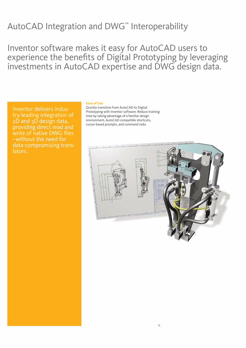
Ease of Use Quickly transition from AutoCAD to Digital Prototyping with Inventor software. Reduce training time by taking advantage of a familiar design environment, AutoCAD compatible shortcuts, cursor-based prompts, and command redo.
Inventor delivers indus-try-leading integration of 2D and 3D design data, providing direct read and write of native DWG files –without the need for data-compromising trans-lators.
16
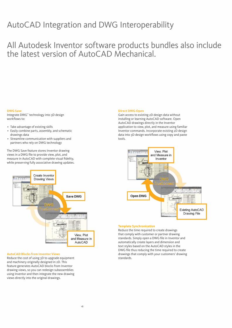
DWG SaveIntegrate DWG™ technology into 3D design workflows to:
Take advantage of existing skillsEasily combine parts, assembly, and schematic drawings dataStreamline communication with suppliers and partners who rely on DWG technology
The DWG Save feature stores Inventor drawing views in a DWG file to provide view, plot, and measure in AutoCAD with complete visual fidelity, while preserving fully associative drawing updates.
AutoCAD Blocks from Inventor ViewsReduce the cost of using 3D to upgrade equipment and machinery originally designed in 2D. This feature generates AutoCAD blocks from Inventor drawing views, so you can redesign subassemblies using Inventor and then integrate the new drawing views directly into the original drawings.
AutoCAD Integration and DWG Interoperability
Direct DWG OpenGain access to existing 2D design data without installing or learning AutoCAD software. Open AutoCAD drawings directly in the Inventor application to view, plot, and measure using familiar Inventor commands. Incorporate existing 2D design data into 3D design workflows using copy and paste tools.
Template SynchronizationReduce the time required to create drawings that comply with customer or partner drawing standards. Simply open a DWG file in Inventor and automatically create layers and dimension and text styles based on the AutoCAD styles in the DWG file thus reducing the time required to create drawings that comply with your customers’ drawing standards.
All Autodesk Inventor software products bundles also include the latest version of AutoCAD Mechanical.
17
Native Translators
Accept projects that use different applications. Autodesk Inventor offers a comprehensive suite of translators, including native translators that read and write files from other CAD tools and translators for industry standard formats such as IGES and STEP.
Native Translators Streamline projects that require opening files from vendors or customers in native formats. And deliver 3D design data to customers or vendors who prefer native file formats. You can easily exchange data between Inventor and CATIA V5™,UGS®, SolidWorks®, and Pro/ENGINEER®. Inventor supports direct import and export of CATIA V5, JT™ 6, JT™7, Parasolid®, and GRANITE files. It also supports direct import of UG-NX™, SolidWorks, Pro/E, and SAT files.
STEP/IGES Enable accurate collaboration with suppliers and customers by sharing and reusing design data between 3D CAD/CAM systems. Read and write design and drawing data using industry-standard formats.
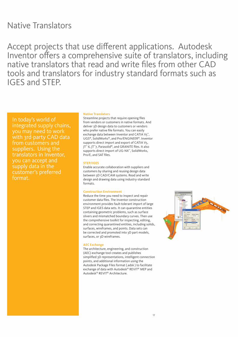
Construction EnvironmentReduce the time you need to inspect and repair customer data files. The Inventor construction environment provides fault-tolerant import of large STEP and IGES data sets. It can quarantine entities containing geometric problems, such as surface slivers and mismatched boundary curves. Then use the comprehensive toolkit for inspecting, editing, and correcting quarantined entities, including solids, surfaces, wireframes, and points. Data sets can be corrected and promoted into 3D part models, surfaces, or 3D wireframes.
AEC Exchange The architecture, engineering, and construction(AEC) exchange tool creates and publishessimplified 3D representations, intelligent connectionpoints, and additional information using the Autodesk Package Files format (.adsk ) to facilitate exchange of data with Autodesk® REVIT® MEP and Autodesk® REVIT® Architecture.
In today’s world of integrated supply chains, you may need to work with 3rd-party CAD data from customers and suppliers. Using the translators in Inventor, you can accept and supply data in the customer’s preferred format.
18
Accelerate the adoption of Digital Prototyping. Inventor software offers a range of learning and reference resources to help you build and maintain your skills as well as quickly make the most of the 3D design environment.
Learning Resources
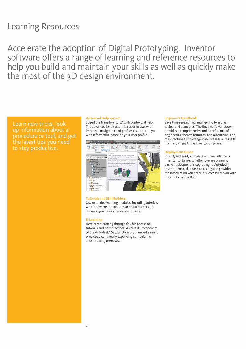
Advanced Help SystemSpeed the transition to 3D with contextual help. The advanced help system is easier to use, with improved navigation and profiles that present you with information based on your user profile.
Tutorials and Skill BuildersUse extended learning modules, including tutorials with “show me” animations and skill builders, to enhance your understanding and skills.
E-Learning Accelerate learning through flexible access to tutorials and best practices. A valuable component of the Autodesk® Subscription program, e-Learning provides a continually expanding curriculum of short training exercises.
Engineer’s Handbook Save time researching engineering formulas, tables, and standards. The Engineer’s Handbook provides a comprehensive online reference of engineering theory, formulas, and algorithms. This manufacturing knowledge base is easily accessible from anywhere in the Inventor software.
Deployment GuideQuicklyand easily complete your installation of Inventor software. Whether you are planning a new deployment or upgrading to Autodesk Inventor 2010, this easy-to-read guide provides the information you need to successfully plan your installation and rollout.
Learn new tricks, lookup information about a procedure or tool, and get the latest tips you need to stay productive.
19
Customization and Automation
Using the Inventor API (application programming interface), you can streamline frequently used procedures and automate specialized workflows that support design standards and engineering processes.
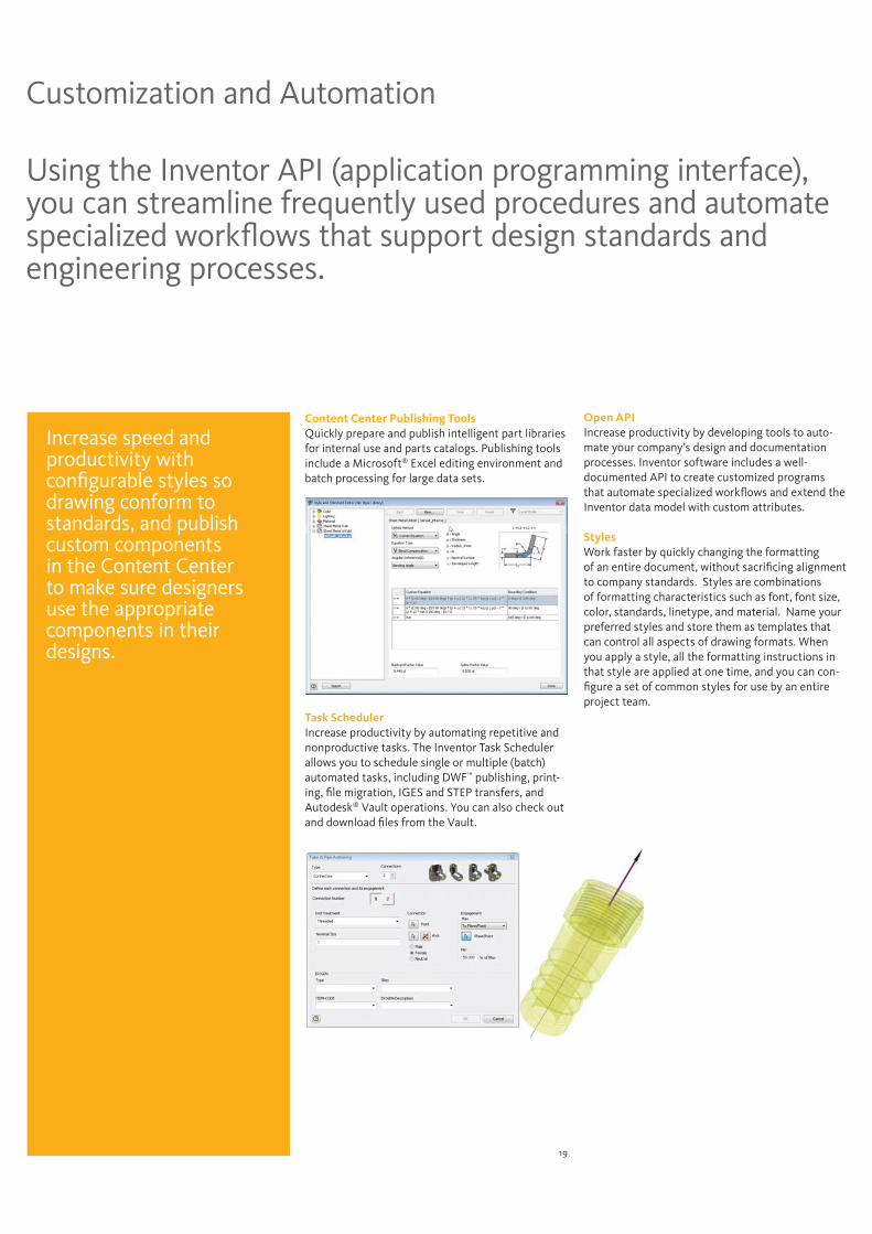
Content Center Publishing ToolsQuickly prepare and publish intelligent part libraries for internal use and parts catalogs. Publishing tools include a Microsoft® Excel editing environment and batch processing for large data sets.
Task SchedulerIncrease productivity by automating repetitive and nonproductive tasks. The Inventor Task Scheduler allows you to schedule single or multiple (batch) automated tasks, including DWF™ publishing, print-ing, file migration, IGES and STEP transfers, and Autodesk® Vault operations. You can also check out and download files from the Vault.
Open APIIncrease productivity by developing tools to auto-mate your company’s design and documentation processes. Inventor software includes a well-documented API to create customized programs that automate specialized workflows and extend the Inventor data model with custom attributes.
StylesWork faster by quickly changing the formattingof an entire document, without sacrificing alignmentto company standards. Styles are combinationsof formatting characteristics such as font, font size, color, standards, linetype, and material. Name your preferred styles and store them as templates that can control all aspects of drawing formats. When you apply a style, all the formatting instructions in that style are applied at one time, and you can con-figure a set of common styles for use by an entire project team.
Increase speed and productivity with configurable styles so drawing conform to standards, and publish custom components in the Content Center to make sure designers use the appropriate components in their designs.
20
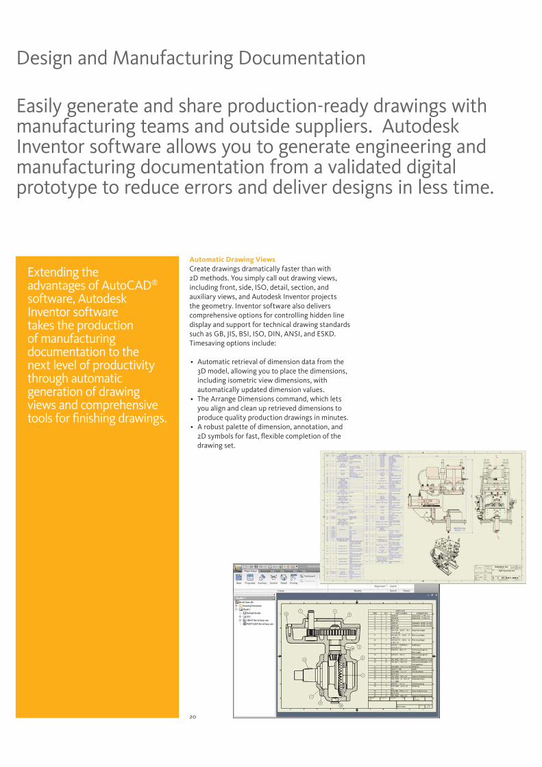
Easily generate and share production-ready drawings with manufacturing teams and outside suppliers. Autodesk Inventor software allows you to generate engineering and manufacturing documentation from a validated digital prototype to reduce errors and deliver designs in less time.
Design and Manufacturing Documentation
Automatic Drawing Views Create drawings dramatically faster than with 2D methods. You simply call out drawing views, including front, side, ISO, detail, section, and auxiliary views, and Autodesk Inventor projects the geometry. Inventor software also delivers comprehensive options for controlling hidden line display and support for technical drawing standards such as GB, JIS, BSI, ISO, DIN, ANSI, and ESKD. Timesaving options include:
Automatic retrieval of dimension data from the 3D model, allowing you to place the dimensions, including isometric view dimensions, with automatically updated dimension values.The Arrange Dimensions command, which lets you align and clean up retrieved dimensions to produce quality production drawings in minutes.A robust palette of dimension, annotation, and 2D symbols for fast, flexible completion of the drawing set.
Extending the advantages of AutoCAD®
software, Autodesk Inventor software takes the production of manufacturing documentation to the next level of productivity through automatic generation of drawing views and comprehensive tools for finishing drawings.
21
Automatic Drawing UpdatesReduce errors and the need for manual update checks with automatic drawing updates. Inventor associates drawing views with the original components, so any change to a part or assembly is automatically reflected in the drawing. Inventor also supports global updates of drawing resources such as title blocks, borders, and sketched symbols.
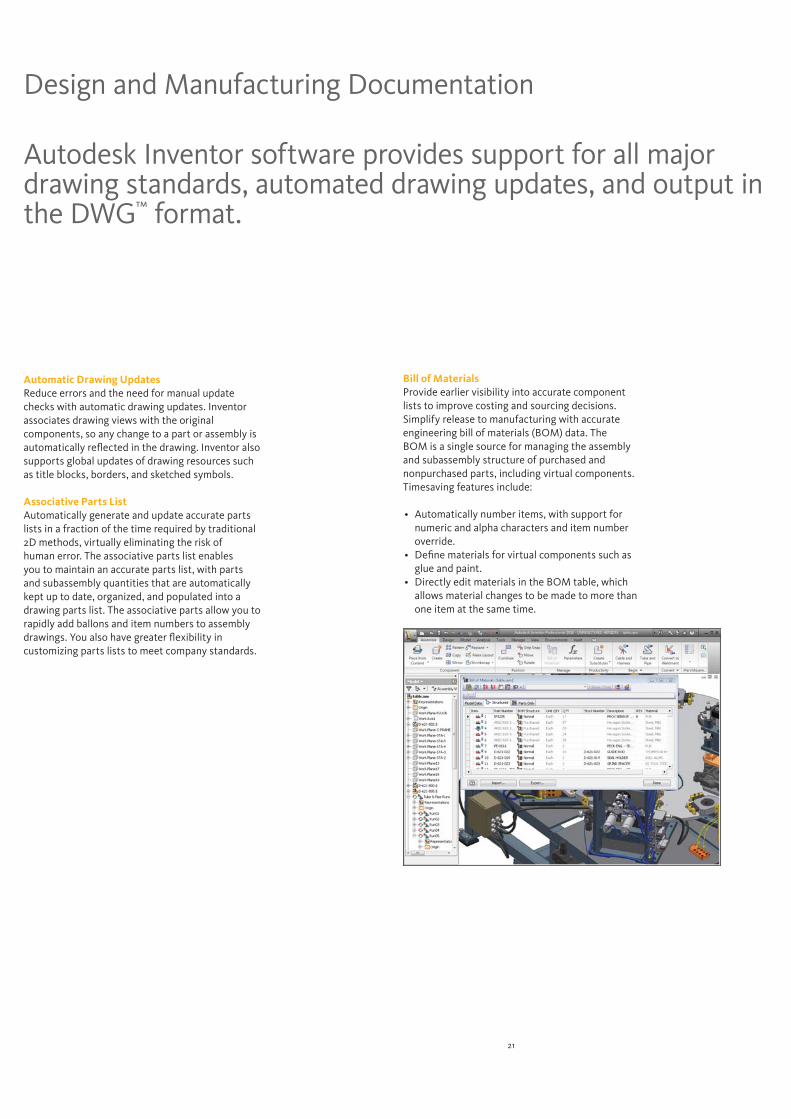
Associative Parts ListAutomatically generate and update accurate parts lists in a fraction of the time required by traditional 2D methods, virtually eliminating the risk of human error. The associative parts list enables you to maintain an accurate parts list, with parts and subassembly quantities that are automatically kept up to date, organized, and populated into a drawing parts list. The associative parts allow you to rapidly add ballons and item numbers to assembly drawings. You also have greater flexibility in customizing parts lists to meet company standards.
Autodesk Inventor software provides support for all major drawing standards, automated drawing updates, and output in the DWG™ format.
Design and Manufacturing Documentation
Bill of Materials Provide earlier visibility into accurate component lists to improve costing and sourcing decisions. Simplify release to manufacturing with accurate engineering bill of materials (BOM) data. The BOM is a single source for managing the assembly and subassembly structure of purchased and nonpurchased parts, including virtual components. Timesaving features include:
Automatically number items, with support for numeric and alpha characters and item number override.Define materials for virtual components such as glue and paint.Directly edit materials in the BOM table, which allows material changes to be made to more than one item at the same time.
22
3D Visualization and Design Communication
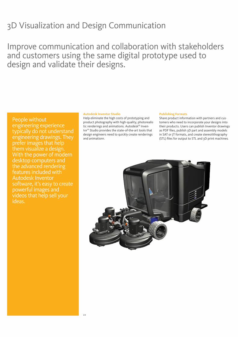
Autodesk Inventor Studio Help eliminate the high costs of prototyping andproduct photography with high-quality, photorealis-tic renderings and animations. Autodesk® Inven-tor® Studio provides the state-of-the-art tools that design engineers need to quickly create renderingsand animations.
Publishing FormatsShare product information with partners and cus-tomers who need to incorporate your designs into their products. Users can publish Inventor drawings as PDF files, publish 3D part and assembly models in SAT or JT formats, and create stereolithography(STL) files for output to STL and 3D print machines.
People without engineering experience typically do not understand engineering drawings. They prefer images that help them visualize a design. With the power of modern desktop computers and the advanced rendering features included with Autodesk Inventor software, it’s easy to create powerful images and videos that help sell your ideas.
Improve communication and collaboration with stakeholders and customers using the same digital prototype used to design and validate their designs.
23
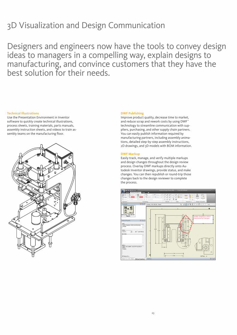
Designers and engineers now have the tools to convey design ideas to managers in a compelling way, explain designs to manufacturing, and convince customers that they have the best solution for their needs.
3D Visualization and Design Communication
Technical IllustrationsUse the Presentation Environment in Inventor software to quickly create technical illustrations, process sheets, training materials, parts manuals, assembly instruction sheets, and videos to train as-sembly teams on the manufacturing floor.
DWF PublishingImprove product quality, decrease time to market, and reduce scrap and rework costs by using DWF™
technology to streamline communication with sup-pliers, purchasing, and other supply chain partners. You can easily publish information required by manufacturing partners, including assembly anima-tions, detailed step-by-step assembly instructions, 2D drawings, and 3D models with BOM information.
DWF Markup Easily track, manage, and verify multiple markups and design changes throughout the design review process. Overlay DWF markups directly onto Au-todesk Inventor drawings, provide status, and make changes. You can then republish or round-trip those changes back to the design reviewer to complete the process.
24
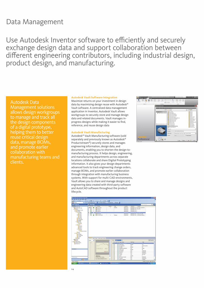
Use Autodesk Inventor software to efficiently and securely exchange design data and support collaboration between different engineering contributors, including industrial design, product design, and manufacturing.
Data Management
Autodesk Vault Software Integration Maximize returns on your investment in design data by maximizing design reuse with Autodesk®
Vault software. A centralized data management application in Inventor, Autodesk Vault allows workgroups to securely store and manage design data and related documents. Vault manages in-progress designs while making it easier to find, reference, and reuse design data
Autodesk Vault Manufacturing Autodesk® Vault Manufacturing software (sold separately and previously known as Autodesk®
Productstream®) securely stores and manages engineering information, design data, and documents, enabling you to shorten the design-to-manufacturing process. It helps design, engineering, and manufacturing departments across separate locations collaborate and share Digital Prototyping information. It also gives your design departments advanced tools to track engineering change orders, manage BOMs, and promote earlier collaboration through integration with manufacturing business systems. With support for multi-CAD environments, Vault allows you to share and manage designs and engineering data created with third-party software and AutoCAD software throughout the product lifecycle.
Autodesk Data Management solutions allows design workgroups to manage and track all the design components of a digital prototype, helping them to better reuse critical design data, manage BOMs, and promote earlier collaboration with manufacturing teams and clients.
25
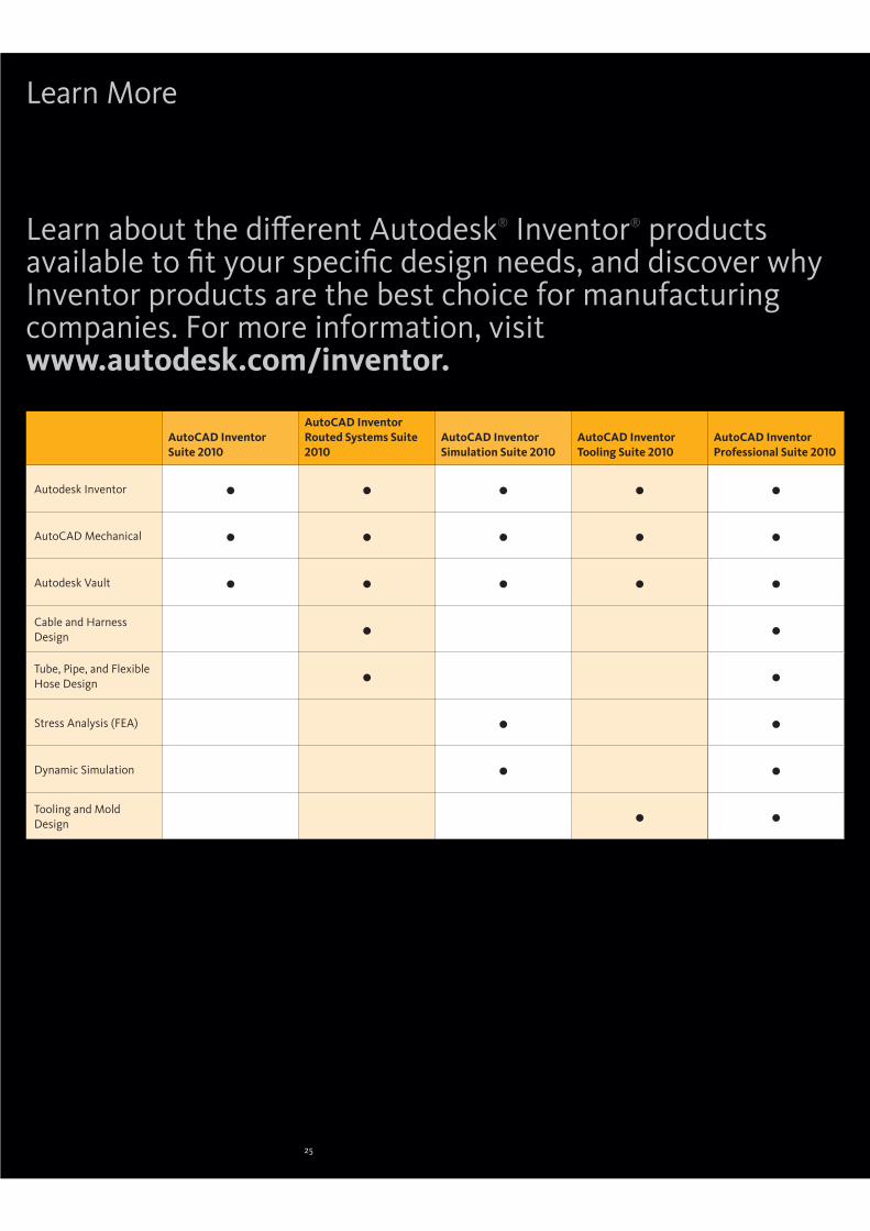
AutoCAD Inventor Suite 2010
AutoCAD Inventor Routed Systems Suite 2010
AutoCAD Inventor Simulation Suite 2010
AutoCAD Inventor Tooling Suite 2010
AutoCAD Inventor Professional Suite 2010
Autodesk Inventor
AutoCAD Mechanical
Autodesk Vault
Cable and Harness Design
Tube, Pipe, and Flexible Hose Design
Stress Analysis (FEA)
Dynamic Simulation
Tooling and Mold Design
Learn about the different Autodesk® Inventor® products available to fit your specific design needs, and discover why Inventor products are the best choice for manufacturing companies. For more information, visit www.autodesk.com/inventor.
Learn More
25

Heading large > KievitPro Regular 23 on 23 pt, 75% black. Ut enim ad mini mim veniami quis nostrud exercitation ullam, corpor suscipit laboris Lorem ipsum etalus siti amet, duis autem conitu secutur adipscing elitsef diam eiusmod magnus. Etion ullam, corpor suscipit laboris Lorem ipsum etalus siti amet, duis autem conitu secutur adipscing elitsef diam eiusmod magnus.
Text heading > KievitPro Bold 8.5 on 10.5 pt, product family colorBody Text > KievitPro Regular 8.5 on 10.5 pt, black. lorem ipsum etalus sit amet, duis autem consecutur adipscing elit, sef diam nonumy eiusmod tempor incident ut labore magna aliquam erat volupat. Ut enim ad minimim veniami quis nostrud exercitation ullam, corpor suscipit laboris nisi ut aliquip ex ea commodo conseauat. Duis autem vel eum irure etalus in reprehjenderit in volupate velit ewsse moestai xom consequat.
Text headingBody Text. Vel illum etalusim eu fugiat nulla pariartur—ignissim qui blandit praes entl upatum delenit aigue duos etalus et molestais excepturisio toccaecet cupidat non. Lorem ipsum etalus sit amet, duis autem consecutur adipscing elit, sef diam nonumy eiusmod te mpor incident ut labore magna aliquam erat.
Text headingBody text. Lorem ipsum etalus sit amet, duis autem consecutur adipscing elit, sef diam nonumy eiusmod tempor incident ut labore magna aliquam erat volupat. Ut enim ad minimim veniami quis nostrud exercitation ullam, corpor suscipit laboris nisi ut aliquip ex ea commodo conseauat. Duis autem vel eum irure etalus in reprehjenderit.
Legal text > KievitPro Regular 6 on 8 pt, black — Registered trademarks of Autodesk, Inc., in the USA and/or other countries. All other product names, brand names, or trademarks belong to their respective holders. © 2008 Autodesk, Inc. All rights reserved. part number
*Free products are subject to the terms and conditions of the end-user license agreement that accompanies download of the software.
Image courtesy of Skidtek Engineering of Charleville, Co. Cork, Ireland
Autodesk, AutoCAD, AliasStudio, Autodesk Inventor, Design Doctor, DWF, DWG, DXF, Inventor, Productstream, and Revit are registered trademarks or trademarks of Autodesk, Inc., and/or its subsidiaries and/or affiliates in the USA and/or other countries. All other brand names, product names, or trademarks belong to their respective holders. Autodesk reserves the right to alter product offerings and specifications at any time without notice, and is not responsible for typographical or graphical errors that may appear in this document. © 2009 Autodesk, Inc. All rights reserved. 464A1-000000-MZ01
Digital Prototyping for the Manufacturing Market
Autodesk is a world-leading supplier of engineering software, providing companies with tools to experience their ideas before they are real. By putting powerful Digital Prototyping technology within the reach of mainstream manufacturers, Autodesk is changing the way manufacturers think about their design processes and is helping them create more productive workflows. The Autodesk approach to Digital Prototyping is unique in that it is scalable, attainable, and cost-effective, which allows a broader group of manufacturers to realize the benefits with minimal disruption to existing workflows, and provides the most straightforward path to creating and maintaining a single digital model in a multidisciplinary engineering environment.
Learn More or PurchaseAccess specialists worldwide who can provide product expertise, a deep understanding of your industry, and value that extends beyond your software purchase. To purchase Autodesk® Inventor® software contact an Autodesk Premier Solutions Provider or Autodesk Authorized Reseller. Locate a reseller near you at www.autodesk.com/reseller.
Autodesk Learning and EducationFrom instructor-led or self-paced classes to online training or education resources, Autodesk offers learning solutions to fit your needs. Get expert guidance at an Autodesk Authorized Training Center (ATC®) site, access learning tools online or at your local bookstore, and validate your experience with Autodesk certifications. Learn more at www.autodesk.com/learning.
Autodesk Services and SupportAccelerate return on investment and optimize productivity with innovative purchase methods, companion products, consulting services, and support from Autodesk and Autodesk authorized partners. Designed to get you up to speed and keep you ahead of the competition, these tools help you make the most of your software purchase—no matter what industry you are in. Learn more at www.autodesk.com/servicesandsupport.
Autodesk SubscriptionGet the benefits of increased productivity, predictable budgeting, and simplified license management with Autodesk® Subscription. You get any new upgrades of your Autodesk software and any incremental product enhancements, if these are released during your Subscription term. In addition, you get exclusive license terms available only to Subscription members. A range of community resources, including web support direct from Autodesk technical experts, self-paced training, and e-Learning, help extend your skills and make Autodesk Subscription the best way to optimize your investment. Learn more at www.autodesk.com/subscription.