Embed Size (px)
Citation preview

Autodesk Official Training Guide
Intermediate
Autodesk®
Inventor®
2010
Sheet Metal Design, Volume 1 Hands-on exercises build on basic concepts and techniques to demonstrate complex modeling practices for forming sheet metal parts, assemblies, and drawings.
527B1-050000-CM11A May 2009

© 2009 Autodesk, Inc. All rights reserved. Except as otherwise permitted by Autodesk, Inc., this publication, or parts thereof, may not be reproduced in any form, by any method, for any purpose. Certain materials included in this publication are reprinted with the permission of the copyright holder.
Trademarks The following are registered trademarks or trademarks of Autodesk, Inc., in the USA and other countries: 3DEC (design/ logo), 3December, 3December.com, 3ds Max, ADI, Alias, Alias (swirl design/logo), AliasStudio, Alias|Wavefront (design/ logo), ATC, AUGI, AutoCAD, AutoCAD Learning Assistance, AutoCAD LT, AutoCAD Simulator, AutoCAD S Q L E x t e n s i o n , AutoCAD SQL Interface, Autodesk, Autodesk Envision, Autodesk Insight, Autodesk Intent, Autodesk Inventor, Autodesk Map, Autodesk MapGuide, Autodesk Streamline, AutoLISP, AutoSnap, AutoSketch, AutoTrack, Backdraft, Built with ObjectARX (logo), Burn, Buzzsaw, CAiCE, Can You Imagine, Character Studio, Cinestream, Civil 3D, Cleaner, Cleaner Central, ClearScale, Colour Warper, Combustion, Communication Specification, Constructware, Content Explorer, Create>what’s>Next> (design/logo), Dancing Baby (image), DesignCenter, Design Doctor, Designer’s Toolkit, DesignKids, DesignProf, DesignServer, DesignStudio, Design|Studio (design/logo), Design Web Format, Discreet, DWF, DWG, DWG (logo), DWG Extreme, DWG TrueConvert, DWG TrueView, DXF, Ecotect, Exposure, Extending the Design Team, Face Robot, FBX, Filmbox, Fire, Flame, Flint, FMDesktop, Freewheel, Frost, GDX Driver, Gmax, Green Building Studio, Heads‐up Design, Heidi, HumanIK, IDEA Server, i‐drop, ImageModeler, iMOUT, Incinerator, Inferno, Inventor, Inventor LT, Kaydara, Kaydara (design/logo), Kynapse, Kynogon, LandXplorer, LocationLogic, Lustre, Matchmover, Maya, Mechanical Desktop, Moonbox, MotionBuilder, Movimento, Mudbox, NavisWorks, ObjectARX, ObjectDBX, Open Reality, Opticore, Opticore Opus, PolarSnap, PortfolioWall, Powered with Autodesk Technology, Productstream, ProjectPoint, ProMaterials, RasterDWG, Reactor, RealDWG, Real‐time Roto, REALVIZ, Recognize, Render Queue, Retimer, Reveal, Revit, Showcase, ShowMotion, SketchBook, Smoke, Softimage, Softimage|XSI (design/logo), SteeringWheels, Stitcher, Stone, StudioTools, Topobase, Toxik, TrustedDWG, ViewCube, Visual, Visual Construction, Visual Drainage, Visual Landscape, Visual Survey, Visual Toolbox, Visual LISP, Voice Reality, Volo, Vtour, Wire, Wiretap, WiretapCentral, XSI, and XSI (design/logo).
The following are registered trademarks or trademarks of Autodesk Canada Co. in the USA and/or Canada and other countries: Backburner, Multi‐Master Editing, River, and Sparks.
The following are registered trademarks or trademarks of Moldflow Corp. in the USA and/or other countries: Moldflow MPA, MPA (design/logo), Moldflow Plastics Advisers, MPI, MPI (design/logo), Moldflow Plastics Insight, MPX, MPX (design/ logo), Moldflow Plastics Xpert. All other brand names, product names, or trademarks belong to their respective holders.
Disclaimer
THIS PUBLICATION AND THE INFORMATION CONTAINED HEREIN IS MADE AVAILABLE BY AUTODESK, INC. “AS IS.” AUTODESK, INC. DISCLAIMS ALL WARRANTIES, EITHER EXPRESS OR IMPLIED, INCLUDING BUT NOT LIMITED TO ANY IMPLIED WARRANTIES OF MERCHANTABILITY OR FITNESS FOR A PARTICULAR PURPOSE REGARDING THESE MATERIALS.
Published by: Autodesk, Inc. 111 Mclnnis Parkway San Rafael, CA 94903, USA
iii
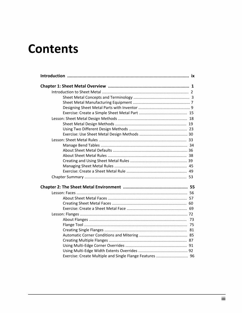
Contents
Introduction ................................................................................................ ix
Chapter 1: Sheet Metal Overview ................................................................ 1 Introduction to Sheet Metal ............................................................................... 2
Sheet Metal Concepts and Terminology ................................................... 3 Sheet Metal Manufacturing Equipment .................................................... 7 Designing Sheet Metal Parts with Inventor ............................................... 9 Exercise: Create a Simple Sheet Metal Part ............................................ 15
Lesson: Sheet Metal Design Methods ............................................................... 18 Sheet Metal Design Methods ................................................................. 19 Using Two Different Design Methods ..................................................... 23 Exercise: Use Sheet Metal Design Methods ............................................ 30
Lesson: Sheet Metal Rules ................................................................................ 33 Manage Bend Tables ............................................................................... 34 About Sheet Metal Defaults .................................................................... 36 About Sheet Metal Rules ........................................................................ 38 Creating and Using Sheet Metal Rules .................................................... 39 Managing Sheet Metal Rules .................................................................. 45 Exercise: Create a Sheet Metal Rule ....................................................... 49
Chapter Summary ............................................................................................. 53
Chapter 2: The Sheet Metal Environment ................................................... 55 Lesson: Faces ..................................................................................................... 56
About Sheet Metal Faces ........................................................................ 57 Creating Sheet Metal Faces .................................................................... 60 Exercise: Create a Sheet Metal Face ....................................................... 69
Lesson: Flanges .................................................................................................. 72
About Flanges ......................................................................................... 73 Flange Tool .............................................................................................. 75 Creating Single Flanges ........................................................................... 81 Automatic Corner Conditions and Mitering ............................................ 85 Creating Multiple Flanges ....................................................................... 87 Using Multi‐Edge Corner Overrides ........................................................ 91 Using Multi‐Edge Width Extents Overrides ............................................. 92 Exercise: Create Multiple and Single Flange Features ............................. 96
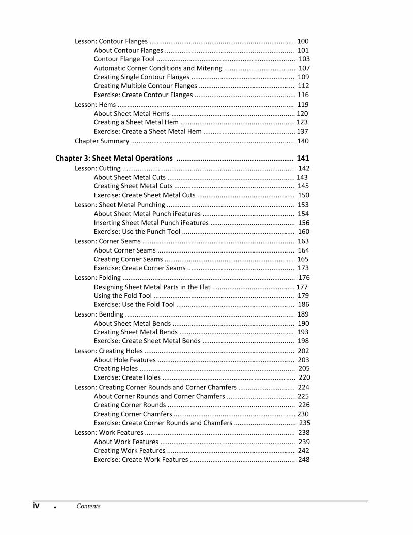
Lesson: Contour Flanges ............................................................................. 100 About Contour Flanges ..................................................................... 101 Contour Flange Tool .......................................................................... 103 Automatic Corner Conditions and Mitering ...................................... 107 Creating Single Contour Flanges ....................................................... 109 Creating Multiple Contour Flanges ................................................... 112 Exercise: Create Contour Flanges ...................................................... 116
Lesson: Hems .............................................................................................. 119 About Sheet Metal Hems .................................................................. 120 Creating a Sheet Metal Hem ............................................................. 123 Exercise: Create a Sheet Metal Hem ................................................. 137
Chapter Summary ....................................................................................... 140
Chapter 3: Sheet Metal Operations ...................................................... 141 Lesson: Cutting ............................................................................................ 142
About Sheet Metal Cuts .................................................................... 143 Creating Sheet Metal Cuts ................................................................ 145 Exercise: Create Sheet Metal Cuts .................................................... 150
Lesson: Sheet Metal Punching .................................................................... 153 About Sheet Metal Punch iFeatures ................................................. 154 Inserting Sheet Metal Punch iFeatures ............................................. 156 Exercise: Use the Punch Tool ............................................................ 160
Lesson: Corner Seams ................................................................................. 163 About Corner Seams ......................................................................... 164 Creating Corner Seams ..................................................................... 165 Exercise: Create Corner Seams ......................................................... 173
Lesson: Folding ............................................................................................ 176 Designing Sheet Metal Parts in the Flat ............................................ 177 Using the Fold Tool ........................................................................... 179 Exercise: Use the Fold Tool ............................................................... 186
Lesson: Bending .......................................................................................... 189 About Sheet Metal Bends ................................................................. 190 Creating Sheet Metal Bends ............................................................. 193 Exercise: Create Sheet Metal Bends ................................................. 198
Lesson: Creating Holes ................................................................................ 202 About Hole Features ......................................................................... 203 Creating Holes ................................................................................... 205 Exercise: Create Holes ....................................................................... 220
Lesson: Creating Corner Rounds and Corner Chamfers .............................. 224 About Corner Rounds and Corner Chamfers ..................................... 225 Creating Corner Rounds .................................................................... 226 Creating Corner Chamfers ................................................................. 230 Exercise: Create Corner Rounds and Chamfers ................................. 235
Lesson: Work Features ................................................................................ 238 About Work Features ........................................................................ 239 Creating Work Features .................................................................... 242 Exercise: Create Work Features ........................................................ 248
iv ■ Contents

vContents ■
Lesson: Pattern Features ............................................................................. 252 About Patterns .................................................................................. 253 Creating Rectangular and Circular Patterns ...................................... 255 Exercise: Create Rectangular and Circular Patterns ........................... 268
Lesson: Mirror Features .............................................................................. 270 About Mirroring Sheet Metal Features ............................................. 271 Mirroring Sheet Metal Features ........................................................ 272 Exercise: Mirror Sheet Metal Features .............................................. 278
Lesson: Lofted Flanges, Rips, and Contour Roll Features ............................ 281
Creating Lofted Flanges .................................................................... 282 Exercise: Create Lofted Flanges ........................................................ 287 Ripping a Sheet Metal Face .............................................................. 291 Exercise: Rip a Sheet Metal Face ...................................................... 296 Creating Contour Roll Features ......................................................... 300 Exercise: Contour Roll ....................................................................... 305
Chapter Summary ....................................................................................... 307
Contents
Chapter 4: Sheet Metal Design Techniques .................................................. 1 Lesson: Sheet Metal Design Approaches ............................................................ 2
Stand‐Alone Sheet Metal Design .............................................................. 3 Creating Stand‐Alone Sheet Metal Parts ................................................... 6 In‐Place Part Creation ............................................................................... 8 Creating Sheet Metal Parts in the Context of an Assembly ..................... 10 Exercise: Use Different Sheet Metal Design Approaches ........................ 14
Lesson: Using Skeletal Models .......................................................................... 18 About Derived Designs ............................................................................ 19 Creating a Sheet Metal Part Using a Skeletal Model ............................... 22
Exercise: Create Sheet Metal Parts Using a Skeletal Model .................... 24 Lesson: Using Legacy DXF/DWG Flat Layout Geometry .................................... 30
About Legacy Flat Layout Data ............................................................... 31 Utilizing Legacy Flat Layout Data ............................................................ 32 Exercise: Use Legacy Flat Layout Data .................................................... 38
Lesson: Using Legacy 3D Geometry .................................................................. 43 About Legacy 3D Geometry .................................................................... 44 Using Imported 3D Geometry ................................................................. 46 Convert a Composite Feature to a Base Feature .................................... 51 Exercise: Import 3D Geometry ................................................................ 59
Lesson: Complex Sheet Metal Creation Techniques .......................................... 63 About Complex Sheet Metal Shapes ....................................................... 64 Creating Complex Sheet Metal Shapes ................................................... 65 About iMates .......................................................................................... 72 Applying iMates to Constrain Sheet Metal Parts .................................... 73 Process for Matching iMates During Placement ..................................... 79 Inferring iMates from Constraints ........................................................... 81 Exercise: Create and Use iMates ............................................................. 84 Exercise: Create Complex Sheet Metal Shapes ....................................... 87
Lesson: Punch Library Setup ............................................................................. 93 Extracting Sheet Metal Punch iFeatures ................................................. 94 Authoring Table‐Driven Punch iFeatures ................................................. 99 Punch Libraries ...................................................................................... 102 Exercise: Create and Reuse Punch iFeatures ......................................... 104
Chapter Summary ........................................................................................... 108
iii
Chapter 5: Using Flat Patterns .............................................................. 109 Lesson: Flat Pattern Creation and Cleanup ................................................. 110
About Flat Patterns ........................................................................... 111 Creating and Editing Flat Patterns .................................................... 113 Cleaning Up Flat Patterns ................................................................. 119 Exercise: Create, Edit, and Clean Up Flat Patterns ............................ 124
Lesson: DXF/DWG Export ............................................................................ 128 About DXF/DWG Export .................................................................... 129 Export Sheet Metal Face ................................................................... 131 Export Sheet Metal Flat Pattern ....................................................... 139 Exercise: Export a Sheet Metal Part .................................................. 147
Chapter Summary ....................................................................................... 150
Chapter 6: Documenting Sheet Metal Designs ...................................... 151 Lesson: Creating Sheet Metal Drawings ...................................................... 152
About Sheet Metal Drawings ............................................................ 153 About 2D Flat Patterns ...................................................................... 155 Creating Sheet Metal Drawings ........................................................ 157 Exercise: Create Sheet Metal Drawings ............................................. 162
Lesson: Sheet Metal Documentation .......................................................... 164 About Bend Annotations ................................................................... 165 Create Bend Notes ............................................................................ 167 Display Model Objects in Drawing Views .......................................... 169 Exercise: Sheet Metal Documentation .............................................. 173
Lesson: Notating Bends and Punches ......................................................... 176 About Bend Notation ........................................................................ 177 Creating Bend Tables ........................................................................ 178 About Punch Notation ...................................................................... 181 Creating Punch Tables ....................................................................... 184 Process of Configuring Punch Notes ................................................. 187 Adding Punch Notes ......................................................................... 190 Editing Punch Notes .......................................................................... 191 Exercise: Create Bend and Punch Tables ........................................... 193 Exercise: Add, Configure, and Edit Punch Notes ............................... 196
Lesson: Cosmetic Centerlines and Bend Order ........................................... 199 Adding Cosmetic Centerlines to the Flat Model ............................... 200 Editing the Bend Order Annotation in the Flat Model ...................... 201 Exercise: Add Cosmetic Centerlines and Edit Bend Order ................. 206
Chapter Summary ........................................................................................ 209
Appendix ............................................................................................... 211
iv ■ Contents

vi ■ Contents

viiAcknowledgements ■
Acknowledgements
The Autodesk Learning team wishes to thank everyone who participated in the development of this project, with special acknowledgement to the authoring contributions and subject matter expertise of Ron Myers and CrWare, LP.
CrWare, LP began publishing courseware for Autodesk® Inventor® in 2001. Since that time, the company has grown to include full‐time curriculum developers, subject matter experts, technical writers, and graphics specialists, each with a unique set of industry experiences and talents that enables CrWare to create content that is both accurate and relevant to meeting the learning needs of its readers and customers.
The company's Founder and General Partner, Ron Myers, has been using Autodesk® products since 1989. During that time, Ron Myers worked in all disciplines of drafting and design, until 1996 when he began a career as an Applications Engineer, Instructor, and Author. Ron Myers has been creating courseware and other training material for Autodesk since 1996 and has written and created training material for AutoCAD®, Autodesk Inventor, AutoCAD® Mechanical, Mechanical Desktop®, and Autodesk® Impression.

viii ■ Acknowledgements
ix
Introduction
Welcome to the Autodesk Inventor 2010 Sheet Metal Design training guide, for use in Authorized Training Center (ATC®) locations, corporate training settings, and other classroom settings.
Although this guide is designed for instructor‐led courses, you can also use it for self‐paced learning. The guide encourages self‐learning through the use of the Autodesk® Inventor® 2010 Help system. This introduction covers the following topics: ■ Course objectives ■ Prerequisites ■ Using this guide ■ CD contents ■ Completing the exercises ■ Installing the exercise data files from the CD ■ Projects ■ Notes, tips, and warnings ■ Feedback This guide is complementary to the software documentation. For detailed explanations of features and functionality, refer to the Help in the software.
Course Objectives After completing this course, you will be able to: ■ Describe the terms and concepts of sheet metal design, create a sheet metal part using two
different creation methods, and create and manage sheet metal styles. ■ Explain the characteristics of a face, flange, contour flange, and hem sheet metal feature and
create sheet metal parts consisting of those features. ■ Produce sheet metal part designs that consist of cuts, punches, corner seams, bends, holes, corner
rounds, corner chamfers, and duplicated features. ■ Create sheet metal designs by using various approaches to sheet metal design, employing skeletal
modeling, using legacy flat pattern and 3D models, and implementing custom sheet metal punch features.
■ Create and edit flat pattern geometry and export your sheet metal parts or faces to DXF and DWG formats.
■ Create and edit sheet metal drawings and document them using annotation tools designed specifically for sheet metal drawings.
x Introduction ■
Prerequisites This course is designed for Autodesk Inventor users who want to learn the essential tools and best practices for sheet metal design using Autodesk Inventor. It is recommended that you have: ■ A working knowledge of Microsoft Windows XP, or Microsoft Windows Vista. ■ Parametric solid modeling concepts. ■ Design or mechanical engineering experience is a plus. Students should have completed the Learning Autodesk Inventor 2010 course or have an equivalent understanding of the Autodesk Inventor 2010 user interface and working environments.
Using This Guide The lessons are independent of each other. However, it is recommended that you complete these lessons in the order that they are presented unless you are familiar with the concepts and functionality described in those lessons. Each chapter contains: ■ Lessons
Usually two or more lessons in each chapter. ■ Exercises
Practical, real‐world examples for you to practice using the functionality you have just learned. Each exercise contains step‐by‐step procedures and graphics to help you complete the exercise successfully.
CD Contents
The CD attached to the back cover of this book contains all the data and drawings you need to complete the exercises in this guide.
Completing the Exercises You can complete the exercise in two ways: using the book or on screen. ■ Using the book
Follow the step‐by‐step exercises in the book. ■ On screen
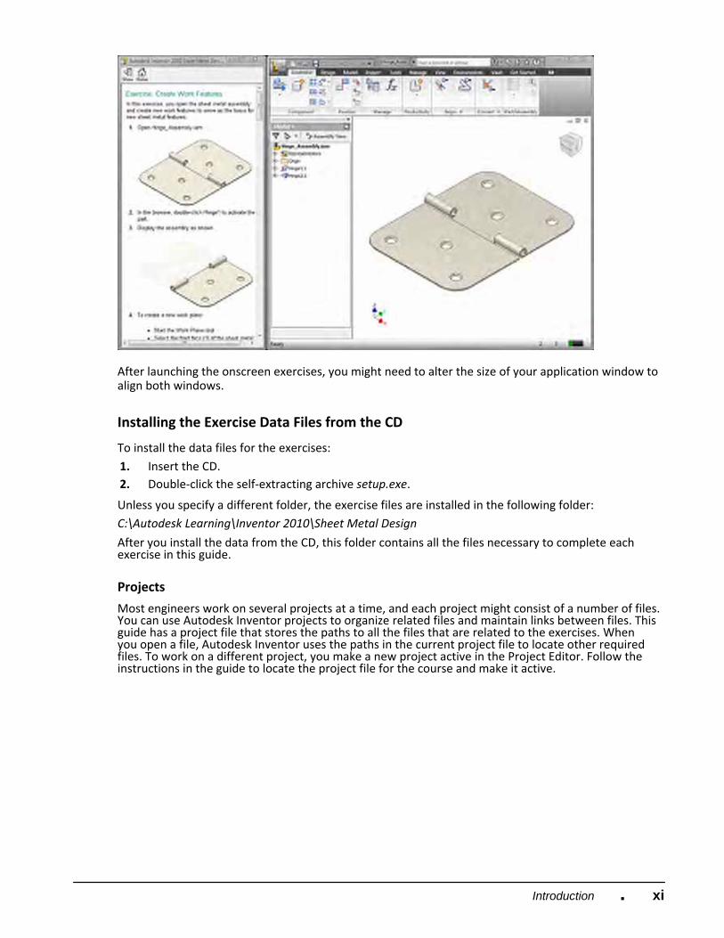
Click the Autodesk Inventor 2010 Sheet Metal Design icon on your desktop, installed from the CD, and follow the step‐by‐step exercises on screen. The onscreen exercises are the same as those in the book. The onscreen version has the advantage that you can concentrate on the screen without having to glance down at your book.
xiIntroduction ■
After launching the onscreen exercises, you might need to alter the size of your application window to align both windows.
Installing the Exercise Data Files from the CD
To install the data files for the exercises: 1. Insert the CD. 2. Double‐click the self‐extracting archive setup.exe.
Unless you specify a different folder, the exercise files are installed in the following folder: C:\Autodesk Learning\Inventor 2010\Sheet Metal Design
After you install the data from the CD, this folder contains all the files necessary to complete each exercise in this guide.
Projects
Most engineers work on several projects at a time, and each project might consist of a number of files. You can use Autodesk Inventor projects to organize related files and maintain links between files. This guide has a project file that stores the paths to all the files that are related to the exercises. When you open a file, Autodesk Inventor uses the paths in the current project file to locate other required files. To work on a different project, you make a new project active in the Project Editor. Follow the instructions in the guide to locate the project file for the course and make it active.
xii Introduction ■
Follow the instructions below to locate the Sheet Metal Design project file for this guide and make it active.
1. Start Autodesk Inventor. 2. In the Application menu, click Manage > Projects.
■ In the Projects dialog box, click Browse. ■ In the Choose Project File dialog box, navigate to C:\Autodesk Learning\Inventor 2010\Sheet Metal
Design. ■ Select Sheet Metal Design.ipj. ■ Click Open.
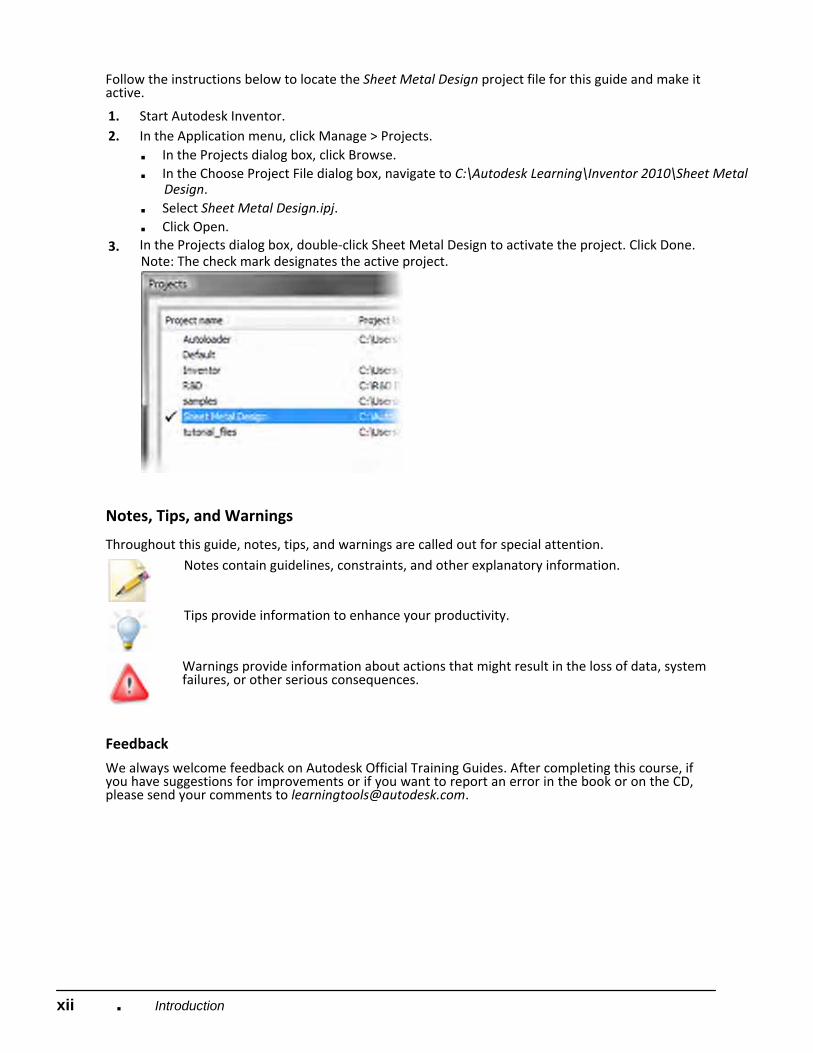
3. In the Projects dialog box, double‐click Sheet Metal Design to activate the project. Click Done. Note: The check mark designates the active project.
Notes, Tips, and Warnings
Throughout this guide, notes, tips, and warnings are called out for special attention. Notes contain guidelines, constraints, and other explanatory information.
Tips provide information to enhance your productivity.
Warnings provide information about actions that might result in the loss of data, system failures, or other serious consequences.
Feedback
We always welcome feedback on Autodesk Official Training Guides. After completing this course, if you have suggestions for improvements or if you want to report an error in the book or on the CD, please send your comments to [email protected].
xiiiIntroduction ■
Digital Prototyping
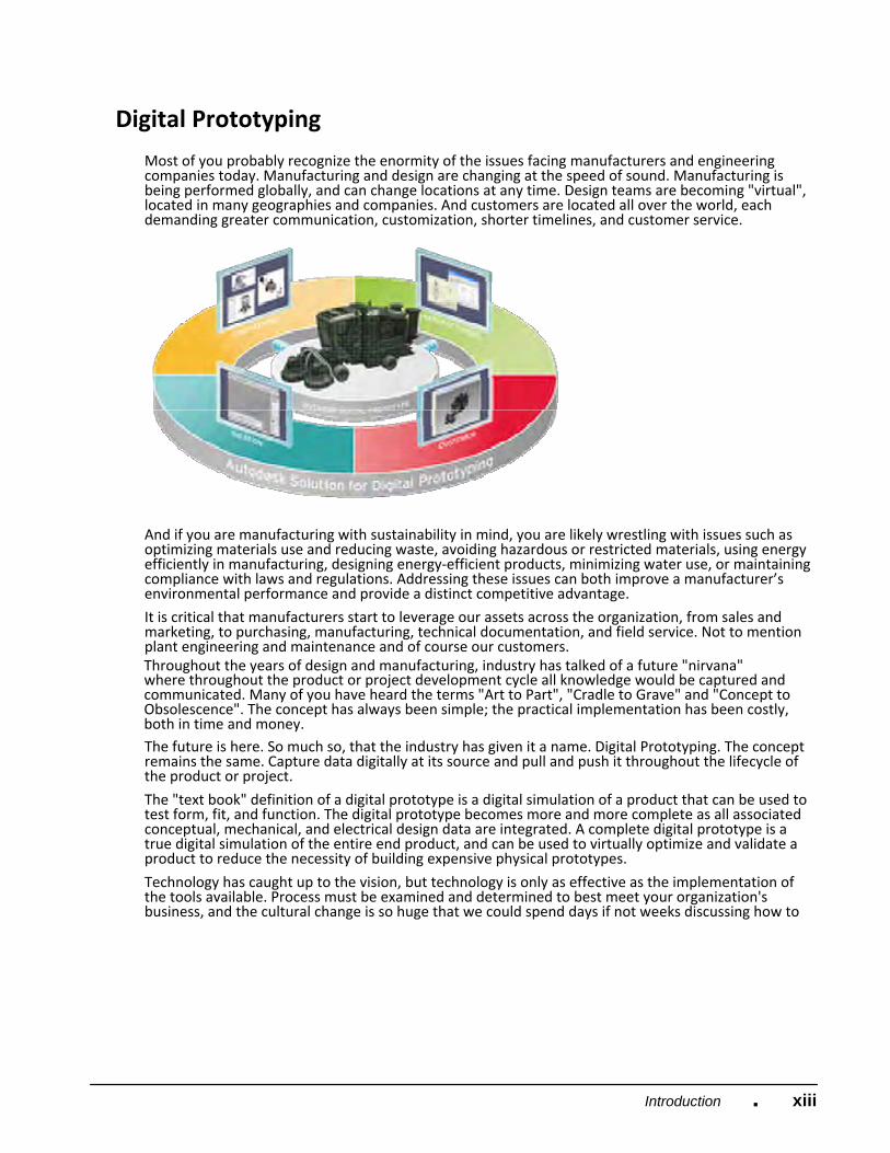
Most of you probably recognize the enormity of the issues facing manufacturers and engineering companies today. Manufacturing and design are changing at the speed of sound. Manufacturing is being performed globally, and can change locations at any time. Design teams are becoming "virtual", located in many geographies and companies. And customers are located all over the world, each demanding greater communication, customization, shorter timelines, and customer service.
And if you are manufacturing with sustainability in mind, you are likely wrestling with issues such as optimizing materials use and reducing waste, avoiding hazardous or restricted materials, using energy efficiently in manufacturing, designing energy‐efficient products, minimizing water use, or maintaining compliance with laws and regulations. Addressing these issues can both improve a manufacturer’s environmental performance and provide a distinct competitive advantage.
It is critical that manufacturers start to leverage our assets across the organization, from sales and marketing, to purchasing, manufacturing, technical documentation, and field service. Not to mention plant engineering and maintenance and of course our customers. Throughout the years of design and manufacturing, industry has talked of a future "nirvana" where throughout the product or project development cycle all knowledge would be captured and communicated. Many of you have heard the terms "Art to Part", "Cradle to Grave" and "Concept to Obsolescence". The concept has always been simple; the practical implementation has been costly, both in time and money.
The future is here. So much so, that the industry has given it a name. Digital Prototyping. The concept remains the same. Capture data digitally at its source and pull and push it throughout the lifecycle of the product or project.
The "text book" definition of a digital prototype is a digital simulation of a product that can be used to test form, fit, and function. The digital prototype becomes more and more complete as all associated conceptual, mechanical, and electrical design data are integrated. A complete digital prototype is a true digital simulation of the entire end product, and can be used to virtually optimize and validate a product to reduce the necessity of building expensive physical prototypes.
Technology has caught up to the vision, but technology is only as effective as the implementation of the tools available. Process must be examined and determined to best meet your organization's business, and the cultural change is so huge that we could spend days if not weeks discussing how to
xiv Introduction ■
best get the 'people' part of the equation to understand and believe that it is not only the "right" thing to do but critical to their future.
For years Autodesk has democratized technology, allowing for attainability, scalability, and affordability. Like AutoCAD® 25 years ago, Autodesk has enabled organizations of any size to practically implement the technology; processes and infrastructure required integrate digital prototyping into your development process.
Digital Prototyping is not a "one size fits all" solution. The sheer array of design projects is overwhelming. How can a consumer products company that must appeal to consumers with a cool look and feel and sell 1000s of units implement the same solution as a custom industrial equipment manufacturer that never designs or builds the same unit twice implement the same solution?
Digital Prototyping is a concept that can be adapted to any design process. The technology and process will differ, but the philosophy is the same.
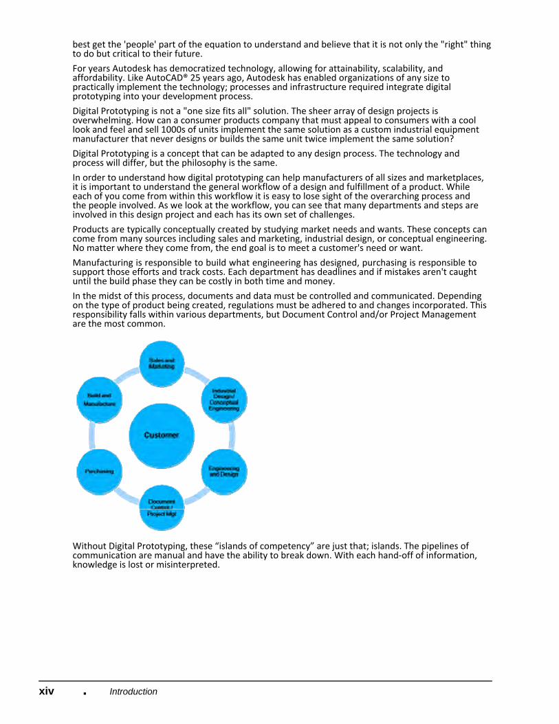
In order to understand how digital prototyping can help manufacturers of all sizes and marketplaces, it is important to understand the general workflow of a design and fulfillment of a product. While each of you come from within this workflow it is easy to lose sight of the overarching process and the people involved. As we look at the workflow, you can see that many departments and steps are involved in this design project and each has its own set of challenges.
Products are typically conceptually created by studying market needs and wants. These concepts can come from many sources including sales and marketing, industrial design, or conceptual engineering. No matter where they come from, the end goal is to meet a customer's need or want.
Manufacturing is responsible to build what engineering has designed, purchasing is responsible to support those efforts and track costs. Each department has deadlines and if mistakes aren't caught until the build phase they can be costly in both time and money.
In the midst of this process, documents and data must be controlled and communicated. Depending on the type of product being created, regulations must be adhered to and changes incorporated. This responsibility falls within various departments, but Document Control and/or Project Management are the most common.
Without Digital Prototyping, these “islands of competency” are just that; islands. The pipelines of communication are manual and have the ability to break down. With each hand‐off of information, knowledge is lost or misinterpreted.
xvIntroduction ■
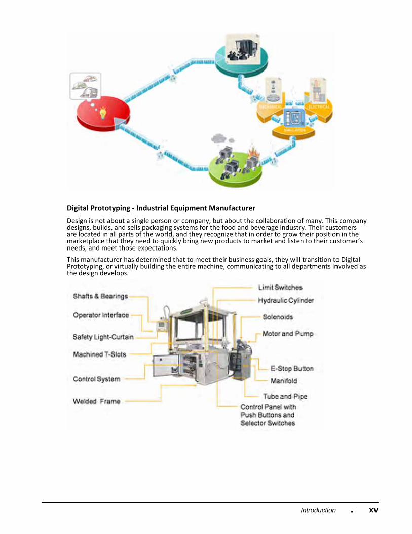
Digital Prototyping ‐ Industrial Equipment Manufacturer
Design is not about a single person or company, but about the collaboration of many. This company designs, builds, and sells packaging systems for the food and beverage industry. Their customers are located in all parts of the world, and they recognize that in order to grow their position in the marketplace that they need to quickly bring new products to market and listen to their customer’s needs, and meet those expectations.
This manufacturer has determined that to meet their business goals, they will transition to Digital Prototyping, or virtually building the entire machine, communicating to all departments involved as the design develops.

xvi Introduction ■
Before the system was manufactured or even physically prototyped, marketing and sales wanted to show customers the concept and allow those customers to give feedback and visualize various options. Those departments utilized Autodesk® Showcase® to dynamically allow customers to interact with the virtual prototype, see various options and make decisions with respect to their needed configuration.
So, how did the process work? The following shows the workflow and products used to complete the design and deliver the equipment to the customer.
In order to keep control of all engineering, design and manufacturing data, Vault Manufacturing was used to vault that data and make it accessible to all project members including mechanical, electrical, manufacturing, purchasing and sales and marketing. Vault Manufacturing allowed this organization to insure that no one was working on the same part of the design at the same time, that everyone was working on the same version of the design, and that downstream departments could view the various sub‐systems and offer input to keep cost down and allow for efficient manufacturing and assembly.
The mechanical design team utilized Autodesk® Inventor® Professional to create the various mechanical sub‐systems of the product. These sub‐systems included the frame, mechanisms, sheet metal enclosures, and mounting hardware for the electrical systems. They also agreed on standards and stuck to them including iproperties, templates, sheet metal styles, naming conventions, dimensioning styles, and hardware.
Another difference with this design is that they used Inventor Professional's capabilities to simulate various mechanisms and analyze parts for form, fit and function as well as safety considerations. As issues arose, electrical design and manufacturing could review the designs through Vault Manufacturing and Design Review to help make suggestions for improvement.
The electrical design team utilized AutoCAD® Electrical to design the electrical systems. Again, this team agreed upon standards to insure consistent device tags, wire numbers and report formats that manufacturing and purchasing could use electronically without reentering the data into their own systems. By using AutoCAD Electrical, wires and device tags weren’t duplicated; components such as relay contacts weren’t over used causing manufacturing and purchasing to have to scramble during the build phase to correct those issues on the shop floor. By using AutoCAD Electrical’s database, accurate parts lists were generated, wire labels were created and imported into their label printer, and a To‐From Wire list was sent to the electricians making their wiring job easy to understand.
One of the biggest changes in engineering was the ability to communicate design intent between the electrical and mechanical teams. While electrical engineers design the schematics and logic, it is typically up to the mechanical teams to mount and physically wire and plumb the electrical and fluid power (hydraulic and pneumatic) devices. Some of these devices could be light curtains, valves, drives, motors, actuators, etc. In the past this was typically done during the physical prototyping phase or during the build of a custom piece of equipment. Electricians would run string from point to point to produce accurate lengths of cables or wires, mechanical design would make their best guess on tube and pipe runs often causing costly changes in manufacturing and delay the testing and debug cycles before a product could ship to a customer site.
By utilizing Inventor Professional's routing capabilities and AutoCAD Electrical's export capabilities, the teams could accurately communicate the design intent, produce nail board drawings for cables, and simulate motion to insure that interferences wouldn’t occur.
Once the digital prototype was created, sales and marketing used Autodesk Showcase to work with customers in a dynamic environment that allowed the customers to virtually experience the equipment, test various options and make quick decisions which shortened the sales cycle.
Once the final configuration of the product was determined, the mechanical team could create detailed drawings in native DWG file format using DWG TruConnect. They could also export DXF files for sheet metal manufacturing, as well as create assembly instructions using Inventor’s presentation capability. These presentations and detailed design documentation were exported to DWF files for the customer.
xviiIntroduction ■
The customer uses Design Review to view models, drawings, and animations and requires no CAD software. It is a free download and available to anyone.
The end result was that this company reduced change orders, saved costs by communicating throughout the process with accurate, accessible information, beat timelines and met customer's expectation. The company might have also made more sustainable choices at key points in the design, engineering and manufacturing process, helping to reduce the number of physical prototypes and decrease waste.
By understanding that process and standards matter, capturing design intent from the beginning and not breaking the digital pipeline as the design evolves, Autodesk's Digital Prototyping can assist any manufacturer to meet and exceed business goals.
Digital Prototyping ‐ Consumer Products
Anyone involved in the design or manufacturing of consumer products understands the unique challenges involved. These challenges include differentiating your brand and product from other competitors, innovating new products that will excite customers to purchase, conveying your product through sales and marketing materials, quick product development cycles, not to mention designing a product that can be mass produced at a reasonable cost and with minimal environmental impact.
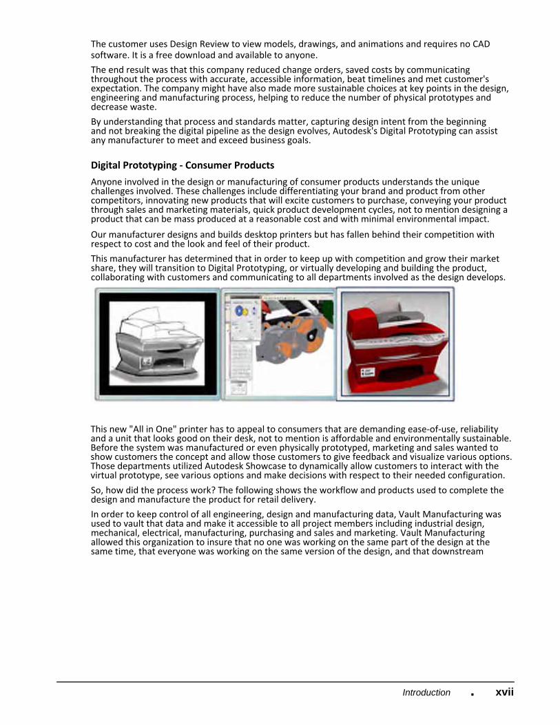
Our manufacturer designs and builds desktop printers but has fallen behind their competition with respect to cost and the look and feel of their product.
This manufacturer has determined that in order to keep up with competition and grow their market share, they will transition to Digital Prototyping, or virtually developing and building the product, collaborating with customers and communicating to all departments involved as the design develops.
This new "All in One" printer has to appeal to consumers that are demanding ease‐of‐use, reliability and a unit that looks good on their desk, not to mention is affordable and environmentally sustainable. Before the system was manufactured or even physically prototyped, marketing and sales wanted to show customers the concept and allow those customers to give feedback and visualize various options. Those departments utilized Autodesk Showcase to dynamically allow customers to interact with the virtual prototype, see various options and make decisions with respect to their needed configuration.
So, how did the process work? The following shows the workflow and products used to complete the design and manufacture the product for retail delivery.
In order to keep control of all engineering, design and manufacturing data, Vault Manufacturing was used to vault that data and make it accessible to all project members including industrial design, mechanical, electrical, manufacturing, purchasing and sales and marketing. Vault Manufacturing allowed this organization to insure that no one was working on the same part of the design at the same time, that everyone was working on the same version of the design, and that downstream
xviii Introduction ■
departments could view the various sub‐systems and offer input to keep cost down and allow for efficient manufacturing and assembly.
Working with market research, the Industrial Design team utilized Alias Design to begin to create conceptual designs of the new printer. Through Alias Design's free‐form sketching environment, industrial design was able to work naturally as though sketching on a pad of paper, and yet capturing those ideas digitally. Through the next weeks, the design team produced several concepts that could be shown to customer focus groups to get feedback and make decisions on the final design.
The marketing team imported the Alias Design models into Autodesk Showcase and created renderings and animations of the various concepts to allow focus groups to dynamically interact with the printer in a typical home office setting. Because the customers could see different configurations and ideas digitally there was no need to take the time and money to produce physical prototypes, therefore shortening the development cycle.
The focus group results showed that the consumers like a combination of two concepts that they had been shown and also chose four colors for the printer that universally appealed to them. The marketing team was able to bring that information back to industrial design. Through the use of Alias Design, design was able to incorporate the two concepts into a single model and make the adjustments that the focus groups requested.
The mechanical design team utilized Autodesk Inventor Professional to import the Alias Design models to create a detailed design that was manufacturable. Through Inventor’s modeling environment various sub‐systems were designed including the molds, mounting brackets for the electronic circuitry and mechanisms.
Another difference with this design is that they used Inventor Professional's capabilities to simulate various mechanisms and analyze parts for form, fit and function as well as safety considerations. As issues arose, electrical design and manufacturing could review the designs through Vault Manufacturing and Design Review to help make suggestions for improvement.
The electrical design team utilized a printed circuit board package and was able to export the physical model into Inventor using the IDF file format. One of the biggest changes in engineering was the ability to communicate design intent between the electrical and mechanical teams. While electrical engineers design the schematics and logic, it is typically up to the mechanical teams to mount and physically wire the electrical systems. In the past this was typically done during the physical prototyping phase and added time and cost to the product development cycle.
Technicians and engineers would run string from point to point to produce accurate lengths of cables or wires and use that string to make physical nailboards to produce prototype harnesses.
By utilizing Inventor Professional's routing capabilities the teams could accurately communicate the design intent, produce nail board drawings for cables, and simulate motion to insure that interferences wouldn't occur.
Throughout the design process the engineering team used Autodesk Showcase to work with sales and marketing to make quick design decisions that allowed the detailed design to continue without having to render the models and hold formal design review meetings.
Once the final configuration of the product was determined, the mechanical team could create detailed drawings in native DWG file format using DWG TruConnect. They could also export files for manufacturing, as well as create assembly instructions using Inventor’s presentation capability.
Prior to the release of the product, sales and marketing used Autodesk Showcase and 3DS Max to produce renderings and animations for customer facing printed material and an interactive website.
The end result was that this company reduced change orders, saved costs by communicating throughout the process with accurate, accessible information, beat timelines and produced a product

xixIntroduction ■
that consumers wanted to purchase at a price point that was profitable for the company and within the consumers price expectation. The company might have also made more sustainable choices at key points in the design, engineering and manufacturing process, helping to reduce the number of physical prototypes and decrease waste.
By understanding that process and standards matter, capturing design intent from the beginning and not breaking the digital pipeline as the design evolves, Autodesk’s Digital Prototyping can assist any manufacturer to meet and exceed business goals.

xx ■ Introduction