Embed Size (px)
Citation preview
Siemens D 31 N · January 2013
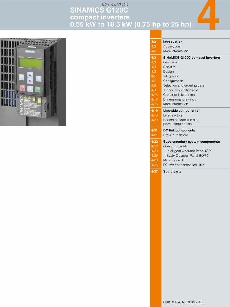
44/2 Introduction4/2 Application4/2 More information
4/3 SINAMICS G120C compact inverters4/3 Overview4/3 Benefits4/3 Design4/5 Integration4/7 Configuration4/8 Selection and ordering data4/9 Technical specifications4/16 Characteristic curves4/17 Dimensional drawings4/18 More information
4/19 Line-side components4/19 Line reactors4/20 Recommended line-side
power components
4/21 DC link components4/21 Braking resistors
4/22 Supplementary system components4/22 Operator panels4/23 Intelligent Operator Panel IOP4/25 Basic Operator Panel BOP-24/26 Memory cards4/26 PC inverter connection kit 2
4/27 Spare parts
SINAMICS G120C compact inverters 0.55 kW to 18.5 kW (0.75 hp to 25 hp)
© Siemens AG 2013
SINAMICS G120C compact inverters0.55 kW to 18.5 kW (0.75 hp to 25 hp)
Introduction
4/2 Siemens D 31 N · January 2013
4
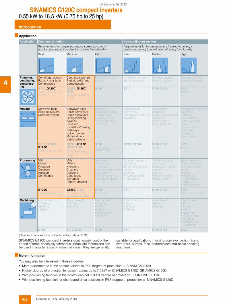
■ Application
(Devices in brackets are not included in Catalog D 31)
SINAMICS G120C compact inverters continuously control the speed of three-phase asynchronous (induction) motors and can be used in a wide range of industrial areas. They are generally
suitable for applications involving conveyor belts, mixers, extruders, pumps, fans, compressors and basic handling machines.
■ More information
You may also be interested in these inverters:• More performance in the control cabinet in IP20 degree of protection SINAMICS G120• Higher degree of protection for power ratings up to 7.5 kW SINAMICS G110D, SINAMICS G120D• With positioning function in the control cabinet in IP20 degree of protection SINAMICS S110• With positioning function for distributed drive solutions in IP65 degree of protection SINAMICS G120D
Application Continuous motion Non-continuous motion
Requirements for torque accuracy / speed accuracy / position accuracy / coordination of axes / functionality
Requirements for torque accuracy / speed accuracy / position accuracy / coordination of axes / functionality
Basic Medium High Basic Medium High
Pumping, ventilating, compress-ing
Centrifugal pumpsRadial / axial fansCompressors
Centrifugal pumpsRadial / axial fansCompressors
Eccentric screw pumps
Hydraulic pumpsMetering pumps
Hydraulic pumpsMetering pumps
Descaling pumpsHydraulic pumps
G110, G120C(G130, G150, GM150, GL150)
G120P, G120C, G120(G130, G150, GM150, GL150)
S120 S110 S110, S120 S120(GM150)
Moving Conveyor beltsRoller conveyorsChain conveyors
Conveyor beltsRoller conveyorsChain conveyorsLifting/lowering devicesElevatorsEscalators/moving walkwaysIndoor cranesMarine drivesCable railways
ElevatorsContainer cranesMining hoistsExcavators for open-cast miningTest bays
Acceleration conveyorsStorage and retrieval machines
Acceleration conveyorsStorage and retrieval machinesCross cuttersReel changers
Storage and retrieval machinesRoboticsPick & placeRotary indexing tablesCross cuttersRoll feedsEngagers/disengagers
G110, G110D, G120C(G130, G150, GM150)
G120D, G120C, G120, S120(G130, G150, S150, GM150, GL150, SM150, DCM)
S120(S150, SM150, SL150, GM150, DCM)
G120D, S110 S110, S120(DCM)
S120(DCM)
Processing MillsMixersKneadersCrushersAgitatorsCentrifuges
MillsMixersKneadersCrushersAgitatorsCentrifugesExtrudersRotary furnaces
ExtrudersWinders and unwindersLead/follower drivesCalendersMain press drivesPrinting machines
Tubular bagging machinesSingle-axis motion controlsuch as• Position profile• Path profile
Tubular bagging machinesSingle-axis motion controlsuch as• Position profile• Path profile
Servo pressesRolling mill drivesMulti-axis motion controlsuch as• Multi-axis
positioning• Cams• Interpolations
G120C(G130, G150, GM150)
G120C, G120(G130, G150, S150, GM150, GL150, DCM)
S120(S150, DCM)
S110 S110, S120 S120(SM150, SL150, DCM)
Machining Main drives for• Turning• Drilling• Milling
Main drives for• Drilling• Sawing
Main drives for• Turning• Drilling• Milling• Gear cutting• Grinding
Axle drives for• Turning• Drilling• Milling
Axle drives for• Drilling• Sawing
Axle drives for• Turning• Drilling• Milling• Lasering• Gear cutting• Grinding• Nibbling and
punching
S110 S110, S120 S120 S110 S110, S120 S120
© Siemens AG 2013
SINAMICS G120C compact inverters0.55 kW to 18.5 kW (0.75 hp to 25 hp)
SINAMICS G120C compact inverters
4/3Siemens D 31 N · January 2013
4
■ Overview
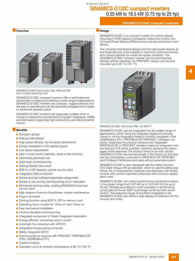
SINAMICS G120C frame sizes FSA, FSB and FSC with mounted blanking cover
SINAMICS G120C compact inverters offer a well-balanced combination of features to address a wide range of applications. SINAMICS G120C inverters are compact, rugged devices that are easy to operate and can be optionally equipped with a basic or advanced operator panel.
SINAMICS G120C inverters are especially suitable when it comes to meeting the requirements of system integrators, OEMs and distributors regarding high productivity and tailored perfor-mance.
■ Benefits
7 Compact design7 Side-by-side design7 High power density, low envelope dimensions7 Simple installation in the tightest space7 Low space requirement7 Use in small control cabinets, close to the machine7 Optimized parameter set7 Optimized commissioning7 Getting Started document7 BOP-2 or IOP operator panels can be used7 Integrated USB connection7 Simple and fast software parameter assignment7 Simple to use during commissioning and in operation7 Minimized training costs, existing SINAMICS know-how
can be used7 High degree of service friendliness, simple maintenance7 Plug-in terminals7 Cloning function using BOP-2, IOP or memory card7 Operating hours counter for "drive on" and "motor on"7 Fast mechanical installation7 Intuitive standard commissioning7 Integrated component of Totally Integrated Automation7 Energy-efficient, sensorless vector control7 Automatic flux reduction with V/f ECO7 Integrated energy saving computer7 Safety Integrated (STO)7 Communications versions with PROFINET, PROFIBUS DP,
CAN, USS/Modbus RTU7 Coated modules7 Operation up to an ambient temperature of 60 °C (140 °F)
■ Design
SINAMICS G120C is a compact inverter for control cabinet mounting in IP20 degree of protection where the Control Unit (CU) and Power Module (PM) function units are combined in one device.
The compact mechanical design and the high power density al-low these devices to be installed in machine control enclosures and control cabinets for maximum space utilization. The SINAMICS G120C compact inverter can be butt-mounted directly, without derating; the PROFINET version can be butt-mounted up to 55 °C (131 °F).
SINAMICS G120C, frame size FSB, with BOP-2
SINAMICS G120C can be integrated into the widest range of applications, either using the integrated digital and analog inputs or via the integrated fieldbus interface (available in the USS/Modbus RTU, PROFIBUS DP, PROFINET, CANopen ver-sions). Especially the product versions with integrated PROFIBUS DP or PROFINET interface make full integration into the Siemens TIA family possible, therefore allowing the advan-tages of the seamless TIA product family to be fully utilized. SINAMICS G120C devices are preset in the factory so that they can be immediately connected to PROFIBUS DP, PROFINET and CANopen fieldbuses and used without parameterization.
SINAMICS G120C is also equipped with the safety function STO (Safe Torque Off) as standard, which is used to safely stop drives. As a consequence, machine manufacturers can simply comply with current machinery directives with minimum associ-ated costs.
SINAMICS G120C can control asynchronous (induction) motors in the power range from 0.37 kW up to 18.5 kW (0.5 hp up to 25 hp). Reliable and efficient motor operation is achieved by using state-of-the-art IGBT technology combined with vector control. The extensive range of functions integrated in the SINAMICS G120C also offers a high degree of protection for the inverter and motor.
© Siemens AG 2013
SINAMICS G120C compact inverters0.55 kW to 18.5 kW (0.75 hp to 25 hp)
SINAMICS G120C compact inverters
4/4 Siemens D 31 N · January 2013
4
■ Design
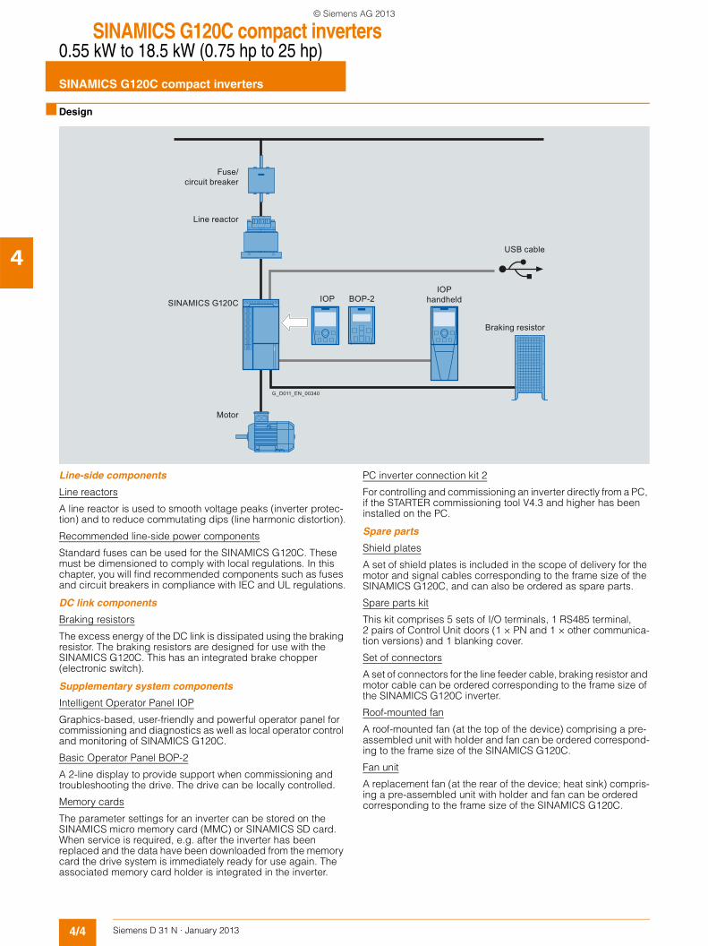
Line-side components
Line reactors
A line reactor is used to smooth voltage peaks (inverter protec-tion) and to reduce commutating dips (line harmonic distortion).
Recommended line-side power components
Standard fuses can be used for the SINAMICS G120C. These must be dimensioned to comply with local regulations. In this chapter, you will find recommended components such as fuses and circuit breakers in compliance with IEC and UL regulations.
DC link components
Braking resistors
The excess energy of the DC link is dissipated using the braking resistor. The braking resistors are designed for use with the SINAMICS G120C. This has an integrated brake chopper (electronic switch).
Supplementary system components
Intelligent Operator Panel IOP
Graphics-based, user-friendly and powerful operator panel for commissioning and diagnostics as well as local operator control and monitoring of SINAMICS G120C.
Basic Operator Panel BOP-2
A 2-line display to provide support when commissioning and troubleshooting the drive. The drive can be locally controlled.
Memory cards
The parameter settings for an inverter can be stored on the SINAMICS micro memory card (MMC) or SINAMICS SD card. When service is required, e.g. after the inverter has been replaced and the data have been downloaded from the memory card the drive system is immediately ready for use again. The associated memory card holder is integrated in the inverter.
PC inverter connection kit 2
For controlling and commissioning an inverter directly from a PC, if the STARTER commissioning tool V4.3 and higher has been installed on the PC.
Spare parts
Shield plates
A set of shield plates is included in the scope of delivery for the motor and signal cables corresponding to the frame size of the SINAMICS G120C, and can also be ordered as spare parts.
Spare parts kit
This kit comprises 5 sets of I/O terminals, 1 RS485 terminal, 2 pairs of Control Unit doors (1 × PN and 1 × other communica-tion versions) and 1 blanking cover.
Set of connectors
A set of connectors for the line feeder cable, braking resistor and motor cable can be ordered corresponding to the frame size of the SINAMICS G120C inverter.
Roof-mounted fan
A roof-mounted fan (at the top of the device) comprising a pre-assembled unit with holder and fan can be ordered correspond-ing to the frame size of the SINAMICS G120C.
Fan unit
A replacement fan (at the rear of the device; heat sink) compris-ing a pre-assembled unit with holder and fan can be ordered corresponding to the frame size of the SINAMICS G120C.
Fuse/circuit breaker
Line reactor
G_D011_EN_00340
Motor
IOP handheld
USB cable
Braking resistor
BOP-2IOPSINAMICS G120C
© Siemens AG 2013
SINAMICS G120C compact inverters0.55 kW to 18.5 kW (0.75 hp to 25 hp)
SINAMICS G120C compact inverters
4/5Siemens D 31 N · January 2013
4
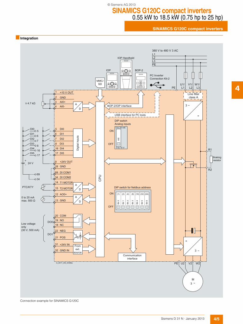
■ Integration
Connection example for SINAMICS G120C
G_D011_EN_00366a
0 to 10 V
0 to 20 mA
PC Inverter Connection Kit-2
OFF
ON
OFF
ON0 to 20 mAmax. 500 Ω
≥ 4.7 kΩBOP-2/IOP interface
USB interface for PC tools
Dig
ital i
nput
s
DIP switchAnalog inputs
Braking resistor
Low voltageonly(30 V, 500 mA)
Line filterclass A
IOP Handheld
380 V to 480 V 3 AC
DIP switch for fieldbus address
Communication interface
Fromext.
source
69
34
17
16
8
7
6
5
+24 V
DI5
DI4
DI3
DI2
DI1
DI0
MMC/SD
PTC/KTY
AI0
DO0
DO1
D
A
GND28
POS21
NEG22
NO19
NC18
COM20
GND13
AO0+12
15
14
69
+24V OUT9
DI517
DI416
DI38
DI27
DI16
DI05
AI0-4
AI0+3
2
1
GND
+10 V OUT
D
A
32
31 +24V IN
GND IN
D
A
DI COM1
34 DI COM2
T1 MOTOR
T2 MOTOR
BOP-2 IOP
CP
U
(1)
Bit
1
(64)(16) (32)(2) (4) (8)
Bit
0
Bit
3
Bit
2
Bit
5
Bit
6
Bit
4
ESC OK
L1L2L3PE
PEU1/L1
V1/L2
W1/L3
~3
=
=
~3
W2V2U2PE
~3M
R1
R2
© Siemens AG 2013
SINAMICS G120C compact inverters0.55 kW to 18.5 kW (0.75 hp to 25 hp)
SINAMICS G120C compact inverters
4/6 Siemens D 31 N · January 2013
4
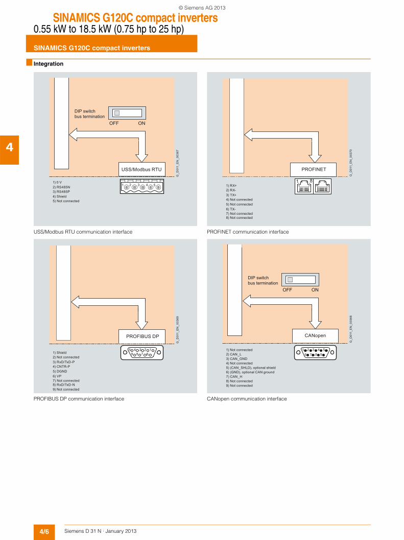
■ Integration
USS/Modbus RTU communication interface
PROFIBUS DP communication interface
PROFINET communication interface
CANopen communication interface
1) 0 V2) RS485N 3) RS485P 4) Shield 5) Not connected
DIP switchbus termination
G_D
011_
EN
_003
67
ONOFF
USS/Modbus RTU
51 2 3 4
G_D
011_
EN
_003
69
2) Not connected1) Shield
3) RxD/TxD-P4) CNTR-P 5) DGND6) VP7) Not connected8) RxD/TxD-N9) Not connected
PROFIBUS DP
59 8 67
1234G
_D01
1_E
N_0
0370
2) RX-1) RX+
3) TX+4) Not connected5) Not connected6) TX-7) Not connected8) Not connected
PROFINET
1 8
DIP switchbus termination
ONOFF
1) Not connected
4) Not connected
8) Not connected9) Not connected
5) (CAN_SHLD), optional shield6) (GND), optional CAN ground
2) CAN_L3) CAN_GND
7) CAN_H
G_D
011_
EN
_003
681 2 3 4
6 97 85
CANopen
© Siemens AG 2013
SINAMICS G120C compact inverters0.55 kW to 18.5 kW (0.75 hp to 25 hp)
SINAMICS G120C compact inverters
4/7Siemens D 31 N · January 2013
4
■ Configuration
The following electronic configuring guides and engineering tools are available for the SINAMICS G120C compact inverters:
Selection guide DT Configurator within the CA 01
The interactive catalog CA 01 – the offline mall of Siemens Industry Automation & Drive Technologies – contains over 100000 products with approximately 5 million possible drive system product variants. The DT Configurator has been devel-oped to facilitate selection of the optimum motor and/or inverter from the wide spectrum of drives. The configurator is integrated as a "selection guide" in this catalog on the DVD-ROM with the selection and configuration tools.
Online DT Configurator
In addition, the DT Configurator can be used in the Internet with-out requiring any installation. The DT Configurator can be found in the Siemens Industry Mall at the following address:www.siemens.com/dt-configurator
SIZER for Siemens Drives engineering tool
The SIZER for Siemens Drives engineering tool makes it easy to engineer the SINAMICS and MICROMASTER 4 drive families. It provides support when selecting the hardware and firmware components necessary to implement a drive task. SIZER for Siemens Drives covers the full range of operations required to configure a complete drive system, from basic single drives to demanding multi-axis applications.
Additional information on the SIZER for Siemens Drives engineering tool is provided in Catalog D 31, chapter Engineering tools.
STARTER commissioning tool
The STARTER commissioning tool allows menu-prompted commissioning, optimization and diagnostics. Apart from the SINAMICS drives, STARTER is also suitable for MICROMASTER 4 devices. For SINAMICS G120D, STARTER version 4.3 and higher.
Additional information on the STARTER commissioning tool is provided in Catalog D 31, chapter Engineering tools.
Drive ES engineering system
Drive ES is the engineering system used to integrate the com-munication, configuration and data management functions of Siemens drive technology into the SIMATIC automation world easily, efficiently and cost-effectively. The STEP 7 Manager user interface provides the ideal basis for this. A variety of software packages are available for SINAMICS – Drive ES Basic, Drive ES SIMATIC and Drive ES PCS 7.1.
Additional information on the Drive ES engineering system is provided in Catalog D 31, chapter Engineering tools.
© Siemens AG 2013
SINAMICS G120C compact inverters0.55 kW to 18.5 kW (0.75 hp to 25 hp)
SINAMICS G120C compact inverters
4/8 Siemens D 31 N · January 2013
4
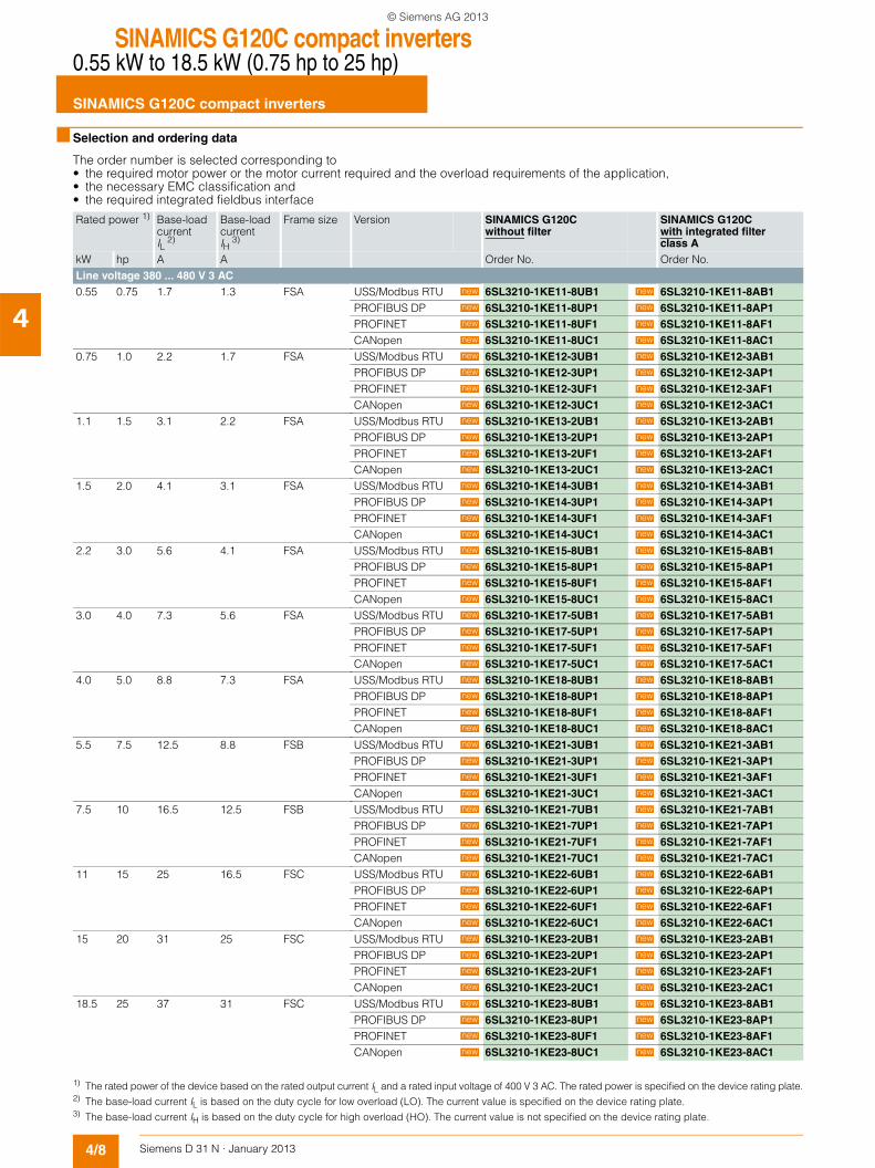
■ Selection and ordering data
The order number is selected corresponding to• the required motor power or the motor current required and the overload requirements of the application,• the necessary EMC classification and• the required integrated fieldbus interface
Rated power 1) Base-load current IL
2)
Base-load current IH
3)
Frame size Version SINAMICS G120Cwithout filter
SINAMICS G120Cwith integrated filter class A
kW hp A A Order No. Order No.Line voltage 380 ... 480 V 3 AC0.55 0.75 1.7 1.3 FSA USS/Modbus RTU 6SL3210-1KE11-8UB1 6SL3210-1KE11-8AB1
PROFIBUS DP 6SL3210-1KE11-8UP1 6SL3210-1KE11-8AP1PROFINET 6SL3210-1KE11-8UF1 6SL3210-1KE11-8AF1CANopen 6SL3210-1KE11-8UC1 6SL3210-1KE11-8AC1
0.75 1.0 2.2 1.7 FSA USS/Modbus RTU 6SL3210-1KE12-3UB1 6SL3210-1KE12-3AB1PROFIBUS DP 6SL3210-1KE12-3UP1 6SL3210-1KE12-3AP1PROFINET 6SL3210-1KE12-3UF1 6SL3210-1KE12-3AF1CANopen 6SL3210-1KE12-3UC1 6SL3210-1KE12-3AC1
1.1 1.5 3.1 2.2 FSA USS/Modbus RTU 6SL3210-1KE13-2UB1 6SL3210-1KE13-2AB1PROFIBUS DP 6SL3210-1KE13-2UP1 6SL3210-1KE13-2AP1PROFINET 6SL3210-1KE13-2UF1 6SL3210-1KE13-2AF1CANopen 6SL3210-1KE13-2UC1 6SL3210-1KE13-2AC1
1.5 2.0 4.1 3.1 FSA USS/Modbus RTU 6SL3210-1KE14-3UB1 6SL3210-1KE14-3AB1PROFIBUS DP 6SL3210-1KE14-3UP1 6SL3210-1KE14-3AP1PROFINET 6SL3210-1KE14-3UF1 6SL3210-1KE14-3AF1CANopen 6SL3210-1KE14-3UC1 6SL3210-1KE14-3AC1
2.2 3.0 5.6 4.1 FSA USS/Modbus RTU 6SL3210-1KE15-8UB1 6SL3210-1KE15-8AB1PROFIBUS DP 6SL3210-1KE15-8UP1 6SL3210-1KE15-8AP1PROFINET 6SL3210-1KE15-8UF1 6SL3210-1KE15-8AF1CANopen 6SL3210-1KE15-8UC1 6SL3210-1KE15-8AC1
3.0 4.0 7.3 5.6 FSA USS/Modbus RTU 6SL3210-1KE17-5UB1 6SL3210-1KE17-5AB1PROFIBUS DP 6SL3210-1KE17-5UP1 6SL3210-1KE17-5AP1PROFINET 6SL3210-1KE17-5UF1 6SL3210-1KE17-5AF1CANopen 6SL3210-1KE17-5UC1 6SL3210-1KE17-5AC1
4.0 5.0 8.8 7.3 FSA USS/Modbus RTU 6SL3210-1KE18-8UB1 6SL3210-1KE18-8AB1PROFIBUS DP 6SL3210-1KE18-8UP1 6SL3210-1KE18-8AP1PROFINET 6SL3210-1KE18-8UF1 6SL3210-1KE18-8AF1CANopen 6SL3210-1KE18-8UC1 6SL3210-1KE18-8AC1
5.5 7.5 12.5 8.8 FSB USS/Modbus RTU 6SL3210-1KE21-3UB1 6SL3210-1KE21-3AB1PROFIBUS DP 6SL3210-1KE21-3UP1 6SL3210-1KE21-3AP1PROFINET 6SL3210-1KE21-3UF1 6SL3210-1KE21-3AF1CANopen 6SL3210-1KE21-3UC1 6SL3210-1KE21-3AC1
7.5 10 16.5 12.5 FSB USS/Modbus RTU 6SL3210-1KE21-7UB1 6SL3210-1KE21-7AB1PROFIBUS DP 6SL3210-1KE21-7UP1 6SL3210-1KE21-7AP1PROFINET 6SL3210-1KE21-7UF1 6SL3210-1KE21-7AF1CANopen 6SL3210-1KE21-7UC1 6SL3210-1KE21-7AC1
11 15 25 16.5 FSC USS/Modbus RTU 6SL3210-1KE22-6UB1 6SL3210-1KE22-6AB1PROFIBUS DP 6SL3210-1KE22-6UP1 6SL3210-1KE22-6AP1PROFINET 6SL3210-1KE22-6UF1 6SL3210-1KE22-6AF1CANopen 6SL3210-1KE22-6UC1 6SL3210-1KE22-6AC1
15 20 31 25 FSC USS/Modbus RTU 6SL3210-1KE23-2UB1 6SL3210-1KE23-2AB1PROFIBUS DP 6SL3210-1KE23-2UP1 6SL3210-1KE23-2AP1PROFINET 6SL3210-1KE23-2UF1 6SL3210-1KE23-2AF1CANopen 6SL3210-1KE23-2UC1 6SL3210-1KE23-2AC1
18.5 25 37 31 FSC USS/Modbus RTU 6SL3210-1KE23-8UB1 6SL3210-1KE23-8AB1PROFIBUS DP 6SL3210-1KE23-8UP1 6SL3210-1KE23-8AP1PROFINET 6SL3210-1KE23-8UF1 6SL3210-1KE23-8AF1CANopen 6SL3210-1KE23-8UC1 6SL3210-1KE23-8AC1
1) The rated power of the device based on the rated output current IL and a rated input voltage of 400 V 3 AC. The rated power is specified on the device rating plate.2) The base-load current IL is based on the duty cycle for low overload (LO). The current value is specified on the device rating plate.3) The base-load current IH is based on the duty cycle for high overload (HO). The current value is not specified on the device rating plate.
new new
new new
new new
new new
new new
new new
new new
new new
new new
new new
new new
new new
new new
new new
new new
new new
new new
new new
new new
new new
new new
new new
new new
new new
new new
new new
new new
new new
new new
new new
new new
new new
new new
new new
new new
new new
new new
new new
new new
new new
new new
new new
new new
new new
new new
new new
new new
new new
© Siemens AG 2013
SINAMICS G120C compact inverters0.55 kW to 18.5 kW (0.75 hp to 25 hp)
SINAMICS G120C compact inverters
4/9Siemens D 31 N · January 2013
4
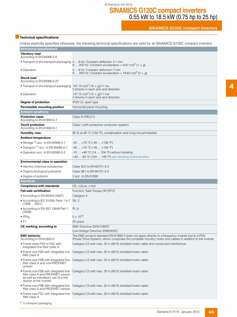
■ Technical specifications
Unless explicitly specified otherwise, the following technical specifications are valid for all SINAMICS G120C compact inverters.
Mechanical specifications
Vibratory loadAccording to EN 60068-2-6
• Transport in the transport packaging 5 ... 9 Hz: Constant deflection 3.1 mm 9 … 200 Hz: Constant acceleration = 9.81 m/s2 (1 × g)
• Operation 2 ... 9 Hz: Constant deflection 7 mm 9 … 200 Hz: Constant acceleration = 19.62 m/s2 (2 × g)
Shock loadAccording to EN 60068-2-27
• Transport in the transport packaging 147.15 m/s2 (15 × g)/11 ms3 shocks in each axis and direction
• Operation 147.15 m/s2 (15 × g)/11 ms3 shocks in each axis and direction
Degree of protection IP20/ UL open type
Permissible mounting position Horizontal panel mounting
Ambient conditions
Protection classAccording to EN 61800-5-1
Class III (PELV1)
Touch protectionAccording to EN 61800-5-1
Class I (with protective conductor system)
Humidity, max. 95 % at 40 °C (104 °F), condensation and icing not permissible
Ambient temperature
• Storage 1) acc. to EN 60068-2-1 -40 … +70 °C (-40 ... +158 °F)
• Transport 1) acc. to EN 60068-2-1 -40 … +70 °C (-40 ... +158 °F)
• Operation acc. to EN 60068-2-2 -10 … +40 °C (14 … 104 °F) without derating>40 … 60 °C (104 … 140 °F) see derating characteristics
Environmental class in operation
• Harmful chemical substances Class 3C2 to EN 60721-3-3
• Organic/biological pollutants Class 3B1 to EN 60721-3-3
• Degree of pollution 2 acc. to EN 61800
Standards
Compliance with standards CE, cULus, c-tick
Fail-safe certification Function: Safe Torque Off (STO)
• According to EN 60204 (2007) Category 3
• According to IEC 61508, Parts 1 to 7 (1998 ... 2001)
SIL 2
• According to EN ISO 13849 Part 1 (2008)
PL d
• PFHD 5 × 10⁻⁸
• T1 20 years
CE marking, according to EMC Directive 2004/108/ECLow-Voltage Directive 2006/95/EC
EMC behaviorAccording to EN 61800-3
The EMC product standard EN 61800-3 does not apply directly to a frequency inverter but to a PDS (Power Drive System), which comprises the complete circuitry, motor and cables in addition to the inverter.
• Frame sizes FSA to FSC with integrated line filter class A
Category C2 with max. 25 m (82 ft) shielded motor cable and conducted interference
• Frame size FSA with integrated line filter class A
Category C2 with max. 25 m (82 ft) shielded motor cable
• Frame size FSB with integrated line filter class A and non-PROFINET version
Category C2 with max. 25 m (82 ft) shielded motor cable
• Frame size FSB with integrated line filter class A and PROFINET version as well as mandatory use of a line reactor at the inverter
Category C2 with max. 25 m (82 ft) shielded motor cable
• Frame size FSB with integrated line filter class A and PROFINET version
Category C3 with max. 25 m (82 ft) shielded motor cable
• Frame size FSC with integrated line filter class A
Category C3 with max. 25 m (82 ft) shielded motor cable
1) In transport packaging.
© Siemens AG 2013
SINAMICS G120C compact inverters0.55 kW to 18.5 kW (0.75 hp to 25 hp)
SINAMICS G120C compact inverters
4/10 Siemens D 31 N · January 2013
4
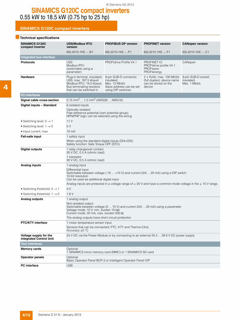
■ Technical specifications
SINAMICS G120C compact inverter
USS/Modbus RTU version
PROFIBUS DP version PROFINET version CANopen version
6SL3210-1KE..-..B1 6SL3210-1KE..-..P1 6SL3210-1KE..-..F1 6SL3210-1KE..-..C1
Integrated bus interface
Protocols USSModbus RTU(switchable using a parameter)
PROFIdrive Profile V4.1 PROFINET IOPROFIdrive profile V4.1PROFIsavePROFIenergy
CANopen
Hardware Plug-in terminal, insulated,USS: max. 187.5 kbaudModbus RTU: 19.2 kbaud,Bus terminating resistors that can be switched in
9-pin SUB-D connector, insulated,Max. 12 Mbit/sSlave address can be set using DIP switches
2 × RJ45, max. 100 Mbit/s (full duplex), device name can be stored on the device
9-pin SUB-D socket, insulated,Max. 1 Mbit/s
I/O interfaces
Signal cable cross-section 0.15 mm2 ... 1.5 mm2 (AWG28 ... AWG16)
Digital inputs – Standard 6 isolated inputsOptically isolated;Free reference potential (own potential group)NPN/PNP logic can be selected using the wiring
• Switching level: 0 → 1 11 V
• Switching level: 1 → 0 5 V
• Input current, max. 15 mA
Fail-safe input 1 safety inputWhen using the standard digital inputs (DI4+DI5)Safety function: Safe Torque OFF (STO)
Digital outputs 1 relay changeover contact30 V DC, 0.5 A (ohmic load)1 transistor30 V DC, 0.5 A (ohmic load)
Analog inputs 1 analog inputDifferential inputSwitchable between voltage (-10 ... +10 V) and current (0/4 ... 20 mA) using a DIP switch10-bit resolutionCan be used as additional digital inputAnalog inputs are protected in a voltage range of ± 30 V and have a common-mode voltage in the ± 15 V range.
• Switching threshold: 0 → 1 4 V
• Switching threshold: 1 → 0 1.6 V
Analog outputs 1 analog outputNon-isolated outputSwitchable between voltage (0 ... 10 V) and current (0/4 ... 20 mA) using a parameterVoltage mode: 10 V, min. burden 10 kΩCurrent mode: 20 mA, max. burden 500 ΩThe analog outputs have short circuit protection
PTC/KTY interface 1 motor temperature sensor inputSensors that can be connected: PTC, KTY and Thermo-Click,Accuracy ±5 °C
Voltage supply for the integrated Control Unit
24 V DC via the Power Module or by connecting to an external 20.4 ... 28.8 V DC power supply
Tool interfaces
Memory cards Optional1 SINAMICS micro memory card (MMC) or 1 SINAMICS SD card
Operator panels OptionalBasic Operator Panel BOP-2 or Intelligent Operator Panel IOP
PC interface USB
© Siemens AG 2013
SINAMICS G120C compact inverters0.55 kW to 18.5 kW (0.75 hp to 25 hp)
SINAMICS G120C compact inverters
4/11Siemens D 31 N · January 2013
4
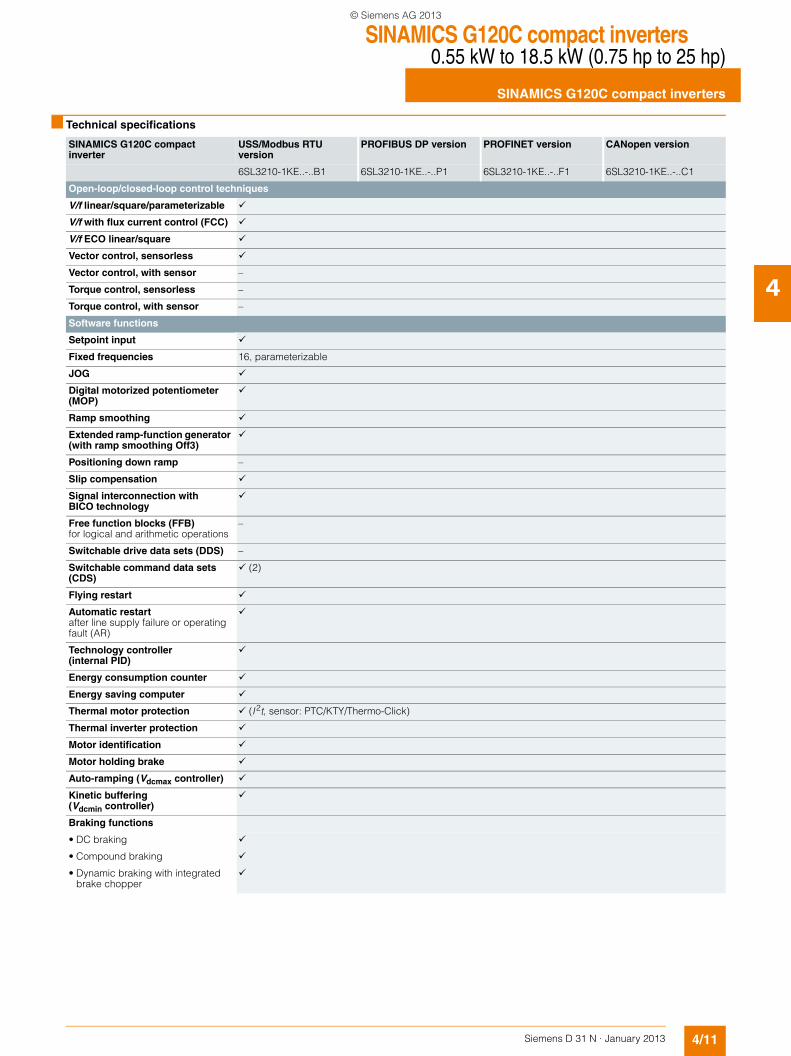
■ Technical specifications
SINAMICS G120C compact inverter
USS/Modbus RTU version
PROFIBUS DP version PROFINET version CANopen version
6SL3210-1KE..-..B1 6SL3210-1KE..-..P1 6SL3210-1KE..-..F1 6SL3210-1KE..-..C1
Open-loop/closed-loop control techniques
V/f linear/square/parameterizable
V/f with flux current control (FCC)
V/f ECO linear/square
Vector control, sensorless
Vector control, with sensor –
Torque control, sensorless –
Torque control, with sensor –
Software functions
Setpoint input
Fixed frequencies 16, parameterizable
JOG
Digital motorized potentiometer (MOP)
Ramp smoothing
Extended ramp-function generator (with ramp smoothing Off3)
Positioning down ramp –
Slip compensation
Signal interconnection with BICO technology
Free function blocks (FFB)for logical and arithmetic operations
–
Switchable drive data sets (DDS) –
Switchable command data sets (CDS)
(2)
Flying restart
Automatic restartafter line supply failure or operating fault (AR)
Technology controller (internal PID)
Energy consumption counter
Energy saving computer
Thermal motor protection (I2t, sensor: PTC/KTY/Thermo-Click)
Thermal inverter protection
Motor identification
Motor holding brake
Auto-ramping (Vdcmax controller)
Kinetic buffering (Vdcmin controller)
Braking functions
• DC braking
• Compound braking
• Dynamic braking with integrated brake chopper
© Siemens AG 2013
SINAMICS G120C compact inverters0.55 kW to 18.5 kW (0.75 hp to 25 hp)
SINAMICS G120C compact inverters
4/12 Siemens D 31 N · January 2013
4
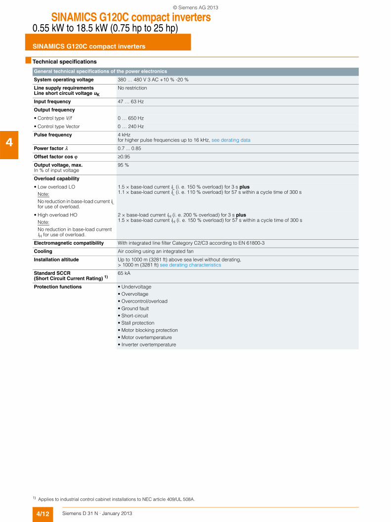
■ Technical specifications
General technical specifications of the power electronics
System operating voltage 380 … 480 V 3 AC +10 % -20 %
Line supply requirementsLine short circuit voltage uK
No restriction
Input frequency 47 … 63 Hz
Output frequency
• Control type V/f 0 … 650 Hz
• Control type Vector 0 … 240 Hz
Pulse frequency 4 kHzfor higher pulse frequencies up to 16 kHz, see derating data
Power factor λ 0.7 ... 0.85
Offset factor cos ϕ ≥0.95
Output voltage, max. In % of input voltage
95 %
Overload capability
• Low overload LONote:No reduction in base-load current IL for use of overload.
1.5 × base-load current IL (i. e. 150 % overload) for 3 s plus1.1 × base-load current IL (i. e. 110 % overload) for 57 s within a cycle time of 300 s
• High overload HONote:No reduction in base-load current IH for use of overload.
2 × base-load current IH (i. e. 200 % overload) for 3 s plus1.5 × base-load current IH (i. e. 150 % overload) for 57 s within a cycle time of 300 s
Electromagnetic compatibility With integrated line filter Category C2/C3 according to EN 61800-3
Cooling Air cooling using an integrated fan
Installation altitude Up to 1000 m (3281 ft) above sea level without derating, > 1000 m (3281 ft) see derating characteristics
Standard SCCR (Short Circuit Current Rating) 1)
65 kA
Protection functions • Undervoltage• Overvoltage• Overcontrol/overload• Ground fault• Short-circuit• Stall protection• Motor blocking protection• Motor overtemperature• Inverter overtemperature
1) Applies to industrial control cabinet installations to NEC article 409/UL 508A.
© Siemens AG 2013
SINAMICS G120C compact inverters0.55 kW to 18.5 kW (0.75 hp to 25 hp)
SINAMICS G120C compact inverters
4/13Siemens D 31 N · January 2013
4
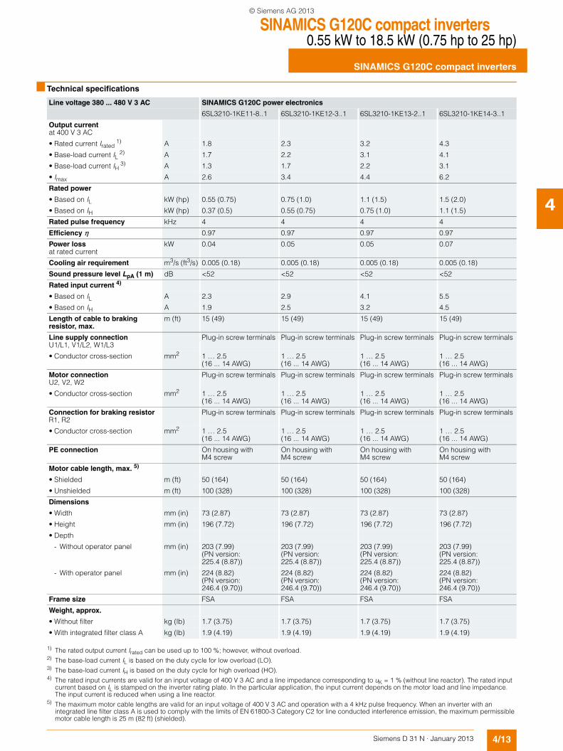
■ Technical specifications
Line voltage 380 ... 480 V 3 AC SINAMICS G120C power electronics
6SL3210-1KE11-8..1 6SL3210-1KE12-3..1 6SL3210-1KE13-2..1 6SL3210-1KE14-3..1
Output currentat 400 V 3 AC
• Rated current Irated 1) A 1.8 2.3 3.2 4.3
• Base-load current IL 2) A 1.7 2.2 3.1 4.1
• Base-load current IH 3) A 1.3 1.7 2.2 3.1
• Imax A 2.6 3.4 4.4 6.2
Rated power
• Based on IL kW (hp) 0.55 (0.75) 0.75 (1.0) 1.1 (1.5) 1.5 (2.0)
• Based on IH kW (hp) 0.37 (0.5) 0.55 (0.75) 0.75 (1.0) 1.1 (1.5)
Rated pulse frequency kHz 4 4 4 4
Efficiency η 0.97 0.97 0.97 0.97
Power lossat rated current
kW 0.04 0.05 0.05 0.07
Cooling air requirement m3/s (ft3/s) 0.005 (0.18) 0.005 (0.18) 0.005 (0.18) 0.005 (0.18)
Sound pressure level LpA (1 m) dB <52 <52 <52 <52
Rated input current 4)
• Based on IL A 2.3 2.9 4.1 5.5
• Based on IH A 1.9 2.5 3.2 4.5
Length of cable to braking resistor, max.
m (ft) 15 (49) 15 (49) 15 (49) 15 (49)
Line supply connectionU1/L1, V1/L2, W1/L3
Plug-in screw terminals Plug-in screw terminals Plug-in screw terminals Plug-in screw terminals
• Conductor cross-section mm2 1 … 2.5(16 ... 14 AWG)
1 … 2.5(16 ... 14 AWG)
1 … 2.5(16 ... 14 AWG)
1 … 2.5(16 ... 14 AWG)
Motor connectionU2, V2, W2
Plug-in screw terminals Plug-in screw terminals Plug-in screw terminals Plug-in screw terminals
• Conductor cross-section mm2 1 … 2.5(16 ... 14 AWG)
1 … 2.5(16 ... 14 AWG)
1 … 2.5(16 ... 14 AWG)
1 … 2.5(16 ... 14 AWG)
Connection for braking resistorR1, R2
Plug-in screw terminals Plug-in screw terminals Plug-in screw terminals Plug-in screw terminals
• Conductor cross-section mm2 1 … 2.5(16 ... 14 AWG)
1 … 2.5(16 ... 14 AWG)
1 … 2.5(16 ... 14 AWG)
1 … 2.5(16 ... 14 AWG)
PE connection On housing with M4 screw
On housing with M4 screw
On housing with M4 screw
On housing with M4 screw
Motor cable length, max. 5)
• Shielded m (ft) 50 (164) 50 (164) 50 (164) 50 (164)
• Unshielded m (ft) 100 (328) 100 (328) 100 (328) 100 (328)
Dimensions
• Width mm (in) 73 (2.87) 73 (2.87) 73 (2.87) 73 (2.87)
• Height mm (in) 196 (7.72) 196 (7.72) 196 (7.72) 196 (7.72)
• Depth
- Without operator panel mm (in) 203 (7.99) (PN version: 225.4 (8.87))
203 (7.99) (PN version: 225.4 (8.87))
203 (7.99) (PN version: 225.4 (8.87))
203 (7.99) (PN version: 225.4 (8.87))
- With operator panel mm (in) 224 (8.82) (PN version: 246.4 (9.70))
224 (8.82) (PN version: 246.4 (9.70))
224 (8.82) (PN version: 246.4 (9.70))
224 (8.82) (PN version: 246.4 (9.70))
Frame size FSA FSA FSA FSA
Weight, approx.
• Without filter kg (lb) 1.7 (3.75) 1.7 (3.75) 1.7 (3.75) 1.7 (3.75)
• With integrated filter class A kg (lb) 1.9 (4.19) 1.9 (4.19) 1.9 (4.19) 1.9 (4.19)
1) The rated output current Irated can be used up to 100 %; however, without overload.2) The base-load current IL is based on the duty cycle for low overload (LO).3) The base-load current IH is based on the duty cycle for high overload (HO).4) The rated input currents are valid for an input voltage of 400 V 3 AC and a line impedance corresponding to uK = 1 % (without line reactor). The rated input
current based on IL is stamped on the inverter rating plate. In the particular application, the input current depends on the motor load and line impedance. The input current is reduced when using a line reactor.
5) The maximum motor cable lengths are valid for an input voltage of 400 V 3 AC and operation with a 4 kHz pulse frequency. When an inverter with an integrated line filter class A is used to comply with the limits of EN 61800-3 Category C2 for line conducted interference emission, the maximum permissible motor cable length is 25 m (82 ft) (shielded).
© Siemens AG 2013
SINAMICS G120C compact inverters0.55 kW to 18.5 kW (0.75 hp to 25 hp)
SINAMICS G120C compact inverters
4/14 Siemens D 31 N · January 2013
4
■ Technical specifications
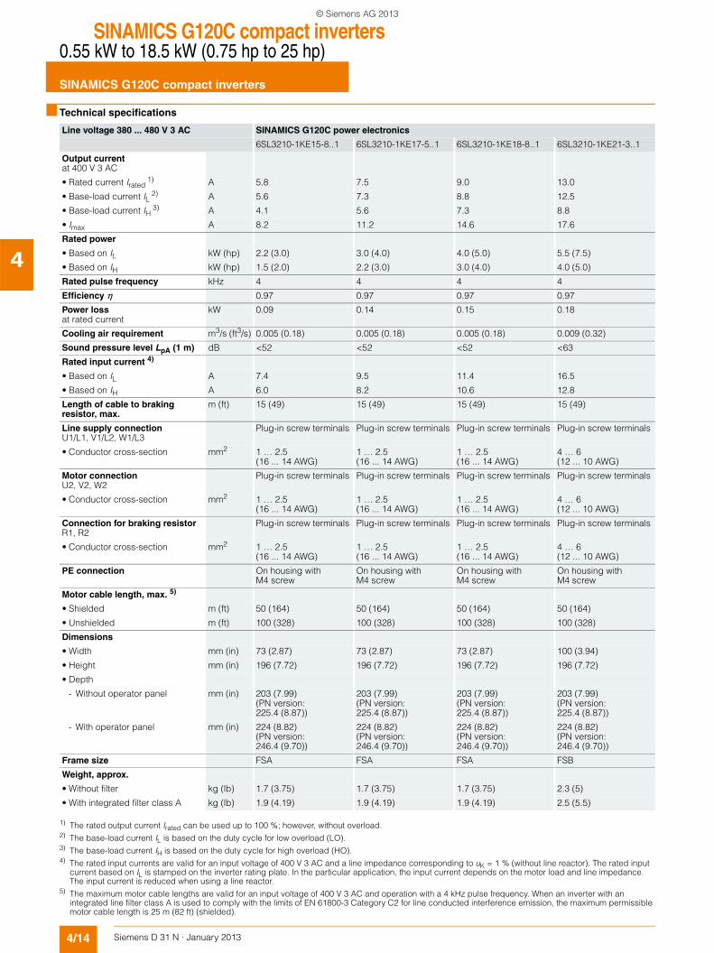
Line voltage 380 ... 480 V 3 AC SINAMICS G120C power electronics
6SL3210-1KE15-8..1 6SL3210-1KE17-5..1 6SL3210-1KE18-8..1 6SL3210-1KE21-3..1
Output currentat 400 V 3 AC
• Rated current Irated 1) A 5.8 7.5 9.0 13.0
• Base-load current IL 2) A 5.6 7.3 8.8 12.5
• Base-load current IH 3) A 4.1 5.6 7.3 8.8
• Imax A 8.2 11.2 14.6 17.6
Rated power
• Based on IL kW (hp) 2.2 (3.0) 3.0 (4.0) 4.0 (5.0) 5.5 (7.5)
• Based on IH kW (hp) 1.5 (2.0) 2.2 (3.0) 3.0 (4.0) 4.0 (5.0)
Rated pulse frequency kHz 4 4 4 4
Efficiency η 0.97 0.97 0.97 0.97
Power lossat rated current
kW 0.09 0.14 0.15 0.18
Cooling air requirement m3/s (ft3/s) 0.005 (0.18) 0.005 (0.18) 0.005 (0.18) 0.009 (0.32)
Sound pressure level LpA (1 m) dB <52 <52 <52 <63
Rated input current 4)
• Based on IL A 7.4 9.5 11.4 16.5
• Based on IH A 6.0 8.2 10.6 12.8
Length of cable to braking resistor, max.
m (ft) 15 (49) 15 (49) 15 (49) 15 (49)
Line supply connectionU1/L1, V1/L2, W1/L3
Plug-in screw terminals Plug-in screw terminals Plug-in screw terminals Plug-in screw terminals
• Conductor cross-section mm2 1 … 2.5(16 ... 14 AWG)
1 … 2.5(16 ... 14 AWG)
1 … 2.5(16 ... 14 AWG)
4 … 6(12 ... 10 AWG)
Motor connectionU2, V2, W2
Plug-in screw terminals Plug-in screw terminals Plug-in screw terminals Plug-in screw terminals
• Conductor cross-section mm2 1 … 2.5(16 ... 14 AWG)
1 … 2.5(16 ... 14 AWG)
1 … 2.5(16 ... 14 AWG)
4 … 6(12 ... 10 AWG)
Connection for braking resistorR1, R2
Plug-in screw terminals Plug-in screw terminals Plug-in screw terminals Plug-in screw terminals
• Conductor cross-section mm2 1 … 2.5(16 ... 14 AWG)
1 … 2.5(16 ... 14 AWG)
1 … 2.5(16 ... 14 AWG)
4 … 6(12 ... 10 AWG)
PE connection On housing with M4 screw
On housing with M4 screw
On housing with M4 screw
On housing with M4 screw
Motor cable length, max. 5)
• Shielded m (ft) 50 (164) 50 (164) 50 (164) 50 (164)
• Unshielded m (ft) 100 (328) 100 (328) 100 (328) 100 (328)
Dimensions
• Width mm (in) 73 (2.87) 73 (2.87) 73 (2.87) 100 (3.94)
• Height mm (in) 196 (7.72) 196 (7.72) 196 (7.72) 196 (7.72)
• Depth
- Without operator panel mm (in) 203 (7.99) (PN version: 225.4 (8.87))
203 (7.99) (PN version: 225.4 (8.87))
203 (7.99) (PN version: 225.4 (8.87))
203 (7.99) (PN version: 225.4 (8.87))
- With operator panel mm (in) 224 (8.82) (PN version: 246.4 (9.70))
224 (8.82) (PN version: 246.4 (9.70))
224 (8.82) (PN version: 246.4 (9.70))
224 (8.82) (PN version: 246.4 (9.70))
Frame size FSA FSA FSA FSB
Weight, approx.
• Without filter kg (lb) 1.7 (3.75) 1.7 (3.75) 1.7 (3.75) 2.3 (5)
• With integrated filter class A kg (lb) 1.9 (4.19) 1.9 (4.19) 1.9 (4.19) 2.5 (5.5)
1) The rated output current Irated can be used up to 100 %; however, without overload.2) The base-load current IL is based on the duty cycle for low overload (LO).3) The base-load current IH is based on the duty cycle for high overload (HO).4) The rated input currents are valid for an input voltage of 400 V 3 AC and a line impedance corresponding to uK = 1 % (without line reactor). The rated input
current based on IL is stamped on the inverter rating plate. In the particular application, the input current depends on the motor load and line impedance. The input current is reduced when using a line reactor.
5) The maximum motor cable lengths are valid for an input voltage of 400 V 3 AC and operation with a 4 kHz pulse frequency. When an inverter with an integrated line filter class A is used to comply with the limits of EN 61800-3 Category C2 for line conducted interference emission, the maximum permissible motor cable length is 25 m (82 ft) (shielded).
© Siemens AG 2013

SINAMICS G120C compact inverters0.55 kW to 18.5 kW (0.75 hp to 25 hp)
SINAMICS G120C compact inverters
4/15Siemens D 31 N · January 2013
4
■ Technical specifications
Line voltage 380 ... 480 V 3 AC SINAMICS G120C power electronics
6SL3210-1KE21-7..1 6SL3210-1KE22-6..1 6SL3210-1KE23-2..1 6SL3210-1KE23-8..1
Output currentat 400 V 3 AC
• Rated current Irated 1) A 17.0 26.0 32.0 38.0
• Base-load current IL 2) A 16.5 25.0 31.0 37.0
• Base-load current IH 3) A 12.5 16.5 25.0 31.0
• Imax A 25.0 33.0 50.0 62.0
Rated power
• Based on IL kW (hp) 7.5 (10) 11.0 (15) 15.0 (20) 18.5 (25)
• Based on IH kW (hp) 5.5 (7.5) 7.5 (10) 11.0 (15) 15.0 (20)
Rated pulse frequency kHz 4 4 4 4
Efficiency η 0.97 0.97 0.97 0.97
Power lossat rated current
kW 0.24 0.35 0.43 0.50
Cooling air requirement m3/s (ft3/s) 0.009 (0.32) 0.018 (0.64) 0.018 (0.64) 0.018 (0.64)
Sound pressure level LpA (1 m) dB <63 <66 <66 <66
Rated input current 4)
• Based on IL A 21.5 33.0 40.6 48.2
• Based on IH A 18.2 24.1 36.4 45.2
Length of cable to braking resistor, max.
m (ft) 15 (49) 15 (49) 15 (49) 15 (49)
Line supply connectionU1/L1, V1/L2, W1/L3
Plug-in screw terminals Plug-in screw terminals Plug-in screw terminals Plug-in screw terminals
• Conductor cross-section mm2 4 … 6(12 ... 10 AWG)
6 … 16(10 ... 5 AWG)
6 … 16(10 ... 5 AWG)
6 … 16(10 ... 5 AWG)
Motor connectionU2, V2, W2
Plug-in screw terminals Plug-in screw terminals Plug-in screw terminals Plug-in screw terminals
• Conductor cross-section mm2 4 … 6(12 ... 10 AWG)
6 … 16(10 ... 5 AWG)
6 … 16(10 ... 5 AWG)
6 … 16(10 ... 5 AWG)
Connection for braking resistorR1, R2
Plug-in screw terminals Plug-in screw terminals Plug-in screw terminals Plug-in screw terminals
• Conductor cross-section mm2 4 … 6(12 ... 10 AWG)
6 … 16(10 ... 5 AWG)
6 … 16(10 ... 5 AWG)
6 … 16(10 ... 5 AWG)
PE connection On housing with M4 screw
On housing with M4 screw
On housing with M4 screw
On housing with M4 screw
Motor cable length, max.5)
• Shielded m (ft) 50 (164) 50 (164) 50 (164) 50 (164)
• Unshielded m (ft) 100 (328) 100 (328) 100 (328) 100 (328)
Dimensions
• Width mm (in) 100 (3.94) 140 (5.51) 140 (5.51) 140 (5.51)
• Height mm (in) 196 (7.72) 295 (11.61) 295 (11.61) 295 (11.61)
• Depth
- Without operator panel mm (in) 203 (7.99) (PN version: 225.4 (8.87))
203 (7.99) (PN version: 225.4 (8.87))
203 (7.99) (PN version: 225.4 (8.87))
203 (7.99) (PN version: 225.4 (8.87))
- With operator panel mm (in) 224 (8.82) (PN version: 246.4 (9.70))
224 (8.82) (PN version: 246.4 (9.70))
224 (8.82) (PN version: 246.4 (9.70))
224 (8.82) (PN version: 246.4 (9.70))
Frame size FSB FSC FSC FSC
Weight, approx.
• Without filter kg (lb) 2.3 (5) 4.4 (9.7) 4.4 (9.7) 4.4 (9.7)
• With integrated filter class A kg (lb) 2.5 (5.5) 4.7 (10.4) 4.7 (10.4) 4.7 (10.4)
1) The rated output current Irated can be used up to 100 %; however, without overload.2) The base-load current IL is based on the duty cycle for low overload (LO).3) The base-load current IH is based on the duty cycle for high overload (HO).4) The rated input currents are valid for an input voltage of 400 V 3 AC and a line impedance corresponding to uK = 1 % (without line reactor). The rated input
current based on IL is stamped on the inverter rating plate. In the particular application, the input current depends on the motor load and line impedance. The input current is reduced when using a line reactor.
5) The maximum motor cable lengths are valid for an input voltage of 400 V 3 AC and operation with a 4 kHz pulse frequency. When an inverter with an integrated line filter class A is used to comply with the limits of EN 61800-3 Category C2 for line conducted interference emission, the maximum permissible motor cable length is 25 m (82 ft) (shielded).
© Siemens AG 2013
SINAMICS G120C compact inverters0.55 kW to 18.5 kW (0.75 hp to 25 hp)
SINAMICS G120C compact inverters
4/16 Siemens D 31 N · January 2013
4
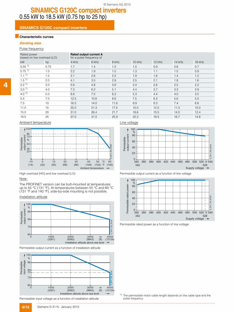
■ Characteristic curves
Derating data
Pulse frequency
Ambient temperature
High overload (HO) and low overload (LO)
Note:
The PROFINET version can be butt-mounted at temperatures up to 55 °C (131 °F). At temperatures between 55 °C and 60 °C (131 °F and 140 °F), side-by-side mounting is not possible.
Installation altitude
Permissible output current as a function of installation altitude
Permissible input voltage as a function of installation altitude
Line voltage
Permissible output current as a function of line voltage
Permissible rated power as a function of line voltage
Rated powerbased on low overload (LO)
Rated output current Afor a pulse frequency of
kW hp 4 kHz 6 kHz 8 kHz 10 kHz 12 kHz 14 kHz 16 kHz
0.55 1) 0.75 1.7 1.4 1.2 1.0 0.9 0.8 0.7
0.75 1) 1.0 2.2 1.9 1.5 1.3 1.1 1.0 0.9
1.1 1) 1.5 3.1 2.6 2.2 1.9 1.6 1.4 1.2
1.5 1) 2.0 4.1 3.5 2.9 2.5 2.1 1.8 1.6
2.2 1) 3.0 5.6 4.8 3.9 3.4 2.8 2.5 2.2
3.0 1) 4.0 7.3 6.2 5.1 4.4 3.7 3.3 2.9
4.0 1) 5.0 8.8 7.5 6.2 5.3 4.4 4.0 3.5
5.5 7.5 12.5 10.6 8.8 7.5 6.3 5.6 5.0
7.5 10 16.5 14.0 11.6 9.9 8.3 7.4 6.6
11.0 15 25.0 21.3 17.5 15.0 12.5 11.3 10.0
15.0 20 31.0 26.4 21.7 18.6 15.5 14.0 12.4
18.5 25 37.0 31.5 25.9 22.2 18.5 16.7 14.8
G_D
011_
EN
_003
90
Per
mis
sibl
eou
tput
cur
rent
Ambient temperature°F(14) (50)(32) (68) (104) (122) (140)(86)
35
85
100
25
50
%75
60°C50-10 4010 30200
80
100%
0 1000 2000 3000 4000m
70
90
60 G_D
011_
EN
_001
04
Installation altitude above sea level
Per
mis
sibl
eou
tput
cur
rent
(3281) (6562) (9843) (ft) (13124)
80
100%
0 1000 2000 3000 4000m
77
70
90
60 G_D
011_
EN
_001
05
Installation altitude above sea level
Per
mis
sibl
ein
put v
olta
ge
(3281) (6562) (9843) (ft) (13124)
20
40
60
80
100%
0340342 528
360 380 400 420 440 460 480 500 V520 540
Per
mis
sibl
eou
tput
cur
rent
G_D
011_
EN
_003
24
Supply voltage
20
40
60
80
100%
0340342 528
360 380 400 420 440 460 480 500 V520 540
Supply voltage
Per
mis
sibl
e ra
ted
pow
er
G_D
011_
EN
_003
25
1) The permissible motor cable length depends on the cable type and the pulse frequency.
© Siemens AG 2013
SINAMICS G120C compact inverters0.55 kW to 18.5 kW (0.75 hp to 25 hp)
SINAMICS G120C compact inverters
4/17Siemens D 31 N · January 2013
4
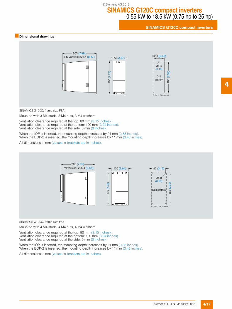
■ Dimensional drawings
SINAMICS G120C, frame size FSA
Mounted with 3 M4 studs, 3 M4 nuts, 3 M4 washers.
Ventilation clearance required at the top: 80 mm (3.15 inches).Ventilation clearance required at the bottom: 100 mm (3.94 inches).Ventilation clearance required at the side: 0 mm (0 inches).
When the IOP is inserted, the mounting depth increases by 21 mm (0.83 inches).When the BOP-2 is inserted, the mounting depth increases by 11 mm (0.43 inches).
All dimensions in mm (values in brackets are in inches).
SINAMICS G120C, frame size FSB
Mounted with 4 M4 studs, 4 M4 nuts, 4 M4 washers.
Ventilation clearance required at the top: 80 mm (3.15 inches).Ventilation clearance required at the bottom: 100 mm (3.94 inches).Ventilation clearance required at the side: 0 mm (0 inches).
When the IOP is inserted, the mounting depth increases by 21 mm (0.83 inches).When the BOP-2 is inserted, the mounting depth increases by 11 mm (0.43 inches).
All dimensions in mm (values in brackets are in inches).
186
(7.3
2)
196
(7.7
2)
73 (2.87)
203 (7.99)62.3 (2.45)
Ø4.5(0.18)
Drillpattern
G_D011_EN_00344a
PN version: 225.4 (8.87)
186
(7.3
2)
196
(7.7
2)
100 (3.94)203 (7.99)
Drill pattern
80 (3.15)
G_D011_EN_00345a
Ø4.8(0.19)
PN version: 225.4 (8.87)
© Siemens AG 2013
SINAMICS G120C compact inverters0.55 kW to 18.5 kW (0.75 hp to 25 hp)
SINAMICS G120C compact inverters
4/18 Siemens D 31 N · January 2013
4
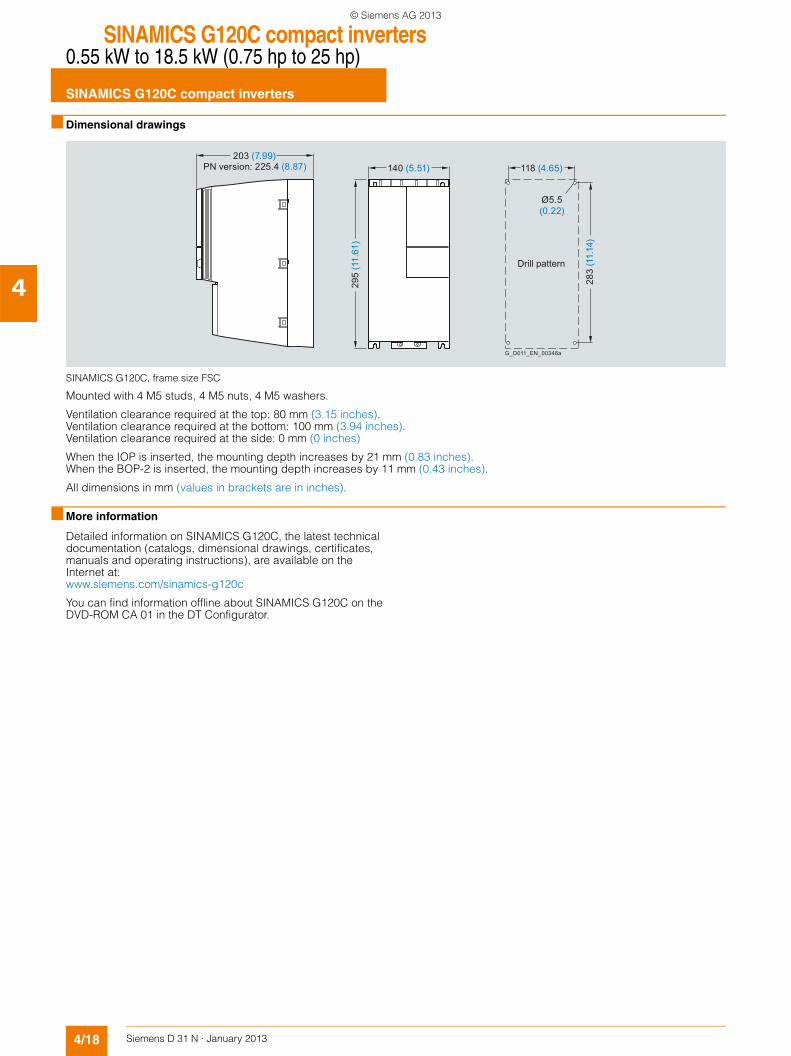
■ Dimensional drawings
SINAMICS G120C, frame size FSC
Mounted with 4 M5 studs, 4 M5 nuts, 4 M5 washers.
Ventilation clearance required at the top: 80 mm (3.15 inches).Ventilation clearance required at the bottom: 100 mm (3.94 inches).Ventilation clearance required at the side: 0 mm (0 inches)
When the IOP is inserted, the mounting depth increases by 21 mm (0.83 inches).When the BOP-2 is inserted, the mounting depth increases by 11 mm (0.43 inches).
All dimensions in mm (values in brackets are in inches).
■ More information
Detailed information on SINAMICS G120C, the latest technical documentation (catalogs, dimensional drawings, certificates, manuals and operating instructions), are available on the Internet at:www.siemens.com/sinamics-g120c
You can find information offline about SINAMICS G120C on the DVD-ROM CA 01 in the DT Configurator.
283
(11.
14)
295
(11.
61)
140 (5.51)203 (7.99)
Drill pattern
118 (4.65)
G_D011_EN_00346a
Ø5.5(0.22)
PN version: 225.4 (8.87)
© Siemens AG 2013
SINAMICS G120C compact inverters0.55 kW to 18.5 kW (0.75 hp to 25 hp)
Line-side componentsLine reactors
4/19Siemens D 31 N · January 2013
4
■ Overview
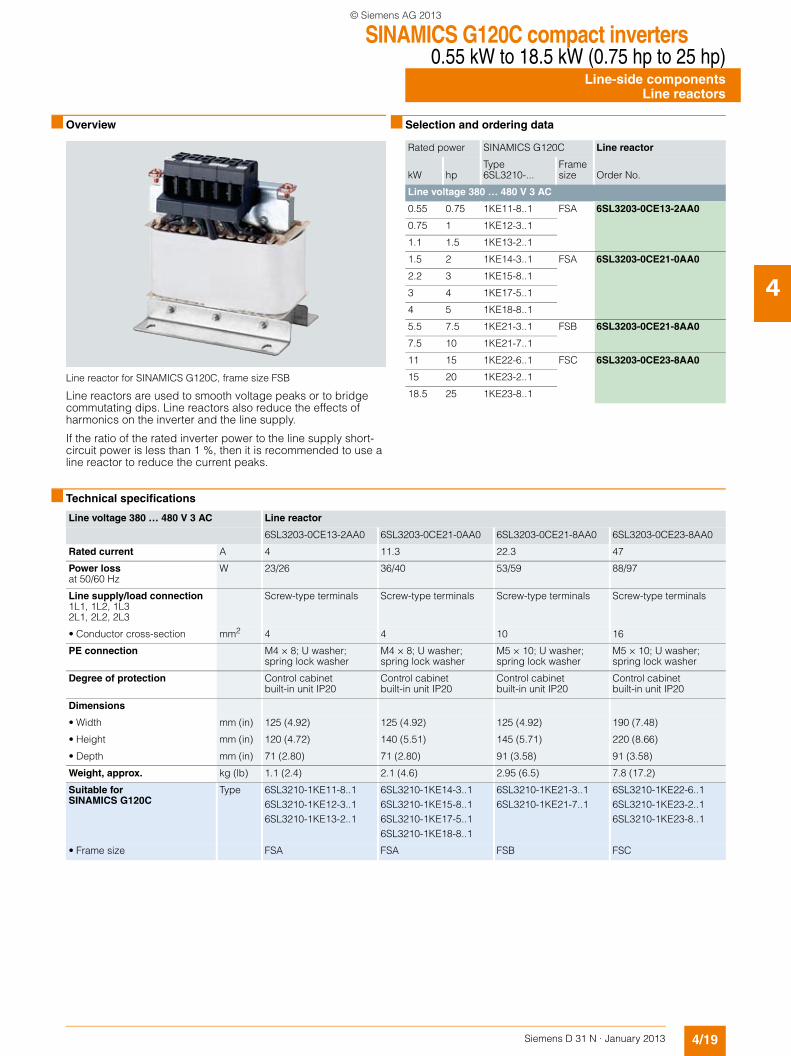
Line reactor for SINAMICS G120C, frame size FSB
Line reactors are used to smooth voltage peaks or to bridge commutating dips. Line reactors also reduce the effects of harmonics on the inverter and the line supply.
If the ratio of the rated inverter power to the line supply short-circuit power is less than 1 %, then it is recommended to use a line reactor to reduce the current peaks.
■ Selection and ordering data
■ Technical specifications
Rated power SINAMICS G120C Line reactor
kW hpType 6SL3210-...
Frame size Order No.
Line voltage 380 … 480 V 3 AC
0.55 0.75 1KE11-8..1 FSA 6SL3203-0CE13-2AA0
0.75 1 1KE12-3..1
1.1 1.5 1KE13-2..1
1.5 2 1KE14-3..1 FSA 6SL3203-0CE21-0AA0
2.2 3 1KE15-8..1
3 4 1KE17-5..1
4 5 1KE18-8..1
5.5 7.5 1KE21-3..1 FSB 6SL3203-0CE21-8AA0
7.5 10 1KE21-7..1
11 15 1KE22-6..1 FSC 6SL3203-0CE23-8AA0
15 20 1KE23-2..1
18.5 25 1KE23-8..1
Line voltage 380 … 480 V 3 AC Line reactor
6SL3203-0CE13-2AA0 6SL3203-0CE21-0AA0 6SL3203-0CE21-8AA0 6SL3203-0CE23-8AA0
Rated current A 4 11.3 22.3 47
Power lossat 50/60 Hz
W 23/26 36/40 53/59 88/97
Line supply/load connection1L1, 1L2, 1L32L1, 2L2, 2L3
Screw-type terminals Screw-type terminals Screw-type terminals Screw-type terminals
• Conductor cross-section mm2 4 4 10 16
PE connection M4 × 8; U washer; spring lock washer
M4 × 8; U washer; spring lock washer
M5 × 10; U washer; spring lock washer
M5 × 10; U washer; spring lock washer
Degree of protection Control cabinet built-in unit IP20
Control cabinet built-in unit IP20
Control cabinet built-in unit IP20
Control cabinet built-in unit IP20
Dimensions
• Width mm (in) 125 (4.92) 125 (4.92) 125 (4.92) 190 (7.48)
• Height mm (in) 120 (4.72) 140 (5.51) 145 (5.71) 220 (8.66)
• Depth mm (in) 71 (2.80) 71 (2.80) 91 (3.58) 91 (3.58)
Weight, approx. kg (lb) 1.1 (2.4) 2.1 (4.6) 2.95 (6.5) 7.8 (17.2)
Suitable for SINAMICS G120C
Type 6SL3210-1KE11-8..16SL3210-1KE12-3..16SL3210-1KE13-2..1
6SL3210-1KE14-3..16SL3210-1KE15-8..16SL3210-1KE17-5..16SL3210-1KE18-8..1
6SL3210-1KE21-3..16SL3210-1KE21-7..1
6SL3210-1KE22-6..16SL3210-1KE23-2..16SL3210-1KE23-8..1
• Frame size FSA FSA FSB FSC
© Siemens AG 2013
SINAMICS G120C compact inverters0.55 kW to 18.5 kW (0.75 hp to 25 hp)Line-side componentsRecommended line-side power components
4/20 Siemens D 31 N · January 2013
4
■ Selection and ordering data
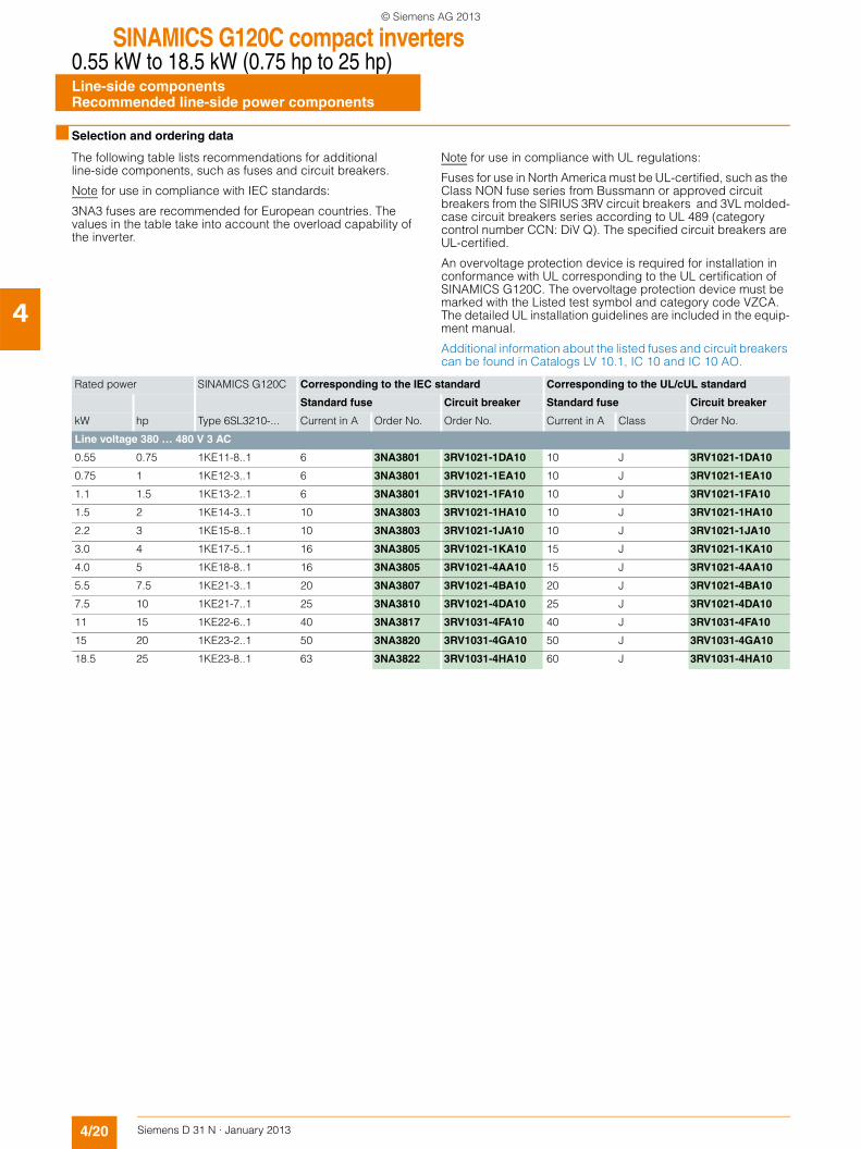
The following table lists recommendations for additional line-side components, such as fuses and circuit breakers.
Note for use in compliance with IEC standards:
3NA3 fuses are recommended for European countries. The values in the table take into account the overload capability of the inverter.
Note for use in compliance with UL regulations:
Fuses for use in North America must be UL-certified, such as the Class NON fuse series from Bussmann or approved circuit breakers from the SIRIUS 3RV circuit breakers and 3VL molded-case circuit breakers series according to UL 489 (category control number CCN: DiV Q). The specified circuit breakers are UL-certified.
An overvoltage protection device is required for installation in conformance with UL corresponding to the UL certification of SINAMICS G120C. The overvoltage protection device must be marked with the Listed test symbol and category code VZCA. The detailed UL installation guidelines are included in the equip-ment manual.
Additional information about the listed fuses and circuit breakers can be found in Catalogs LV 10.1, IC 10 and IC 10 AO.
Rated power SINAMICS G120C Corresponding to the IEC standard Corresponding to the UL/cUL standard
Standard fuse Circuit breaker Standard fuse Circuit breaker
kW hp Type 6SL3210-... Current in A Order No. Order No. Current in A Class Order No.
Line voltage 380 … 480 V 3 AC
0.55 0.75 1KE11-8..1 6 3NA3801 3RV1021-1DA10 10 J 3RV1021-1DA10
0.75 1 1KE12-3..1 6 3NA3801 3RV1021-1EA10 10 J 3RV1021-1EA10
1.1 1.5 1KE13-2..1 6 3NA3801 3RV1021-1FA10 10 J 3RV1021-1FA10
1.5 2 1KE14-3..1 10 3NA3803 3RV1021-1HA10 10 J 3RV1021-1HA10
2.2 3 1KE15-8..1 10 3NA3803 3RV1021-1JA10 10 J 3RV1021-1JA10
3.0 4 1KE17-5..1 16 3NA3805 3RV1021-1KA10 15 J 3RV1021-1KA10
4.0 5 1KE18-8..1 16 3NA3805 3RV1021-4AA10 15 J 3RV1021-4AA10
5.5 7.5 1KE21-3..1 20 3NA3807 3RV1021-4BA10 20 J 3RV1021-4BA10
7.5 10 1KE21-7..1 25 3NA3810 3RV1021-4DA10 25 J 3RV1021-4DA10
11 15 1KE22-6..1 40 3NA3817 3RV1031-4FA10 40 J 3RV1031-4FA10
15 20 1KE23-2..1 50 3NA3820 3RV1031-4GA10 50 J 3RV1031-4GA10
18.5 25 1KE23-8..1 63 3NA3822 3RV1031-4HA10 60 J 3RV1031-4HA10
© Siemens AG 2013
SINAMICS G120C compact inverters0.55 kW to 18.5 kW (0.75 hp to 25 hp)
DC link componentsBraking resistors
4/21Siemens D 31 N · January 2013
4
■ Overview
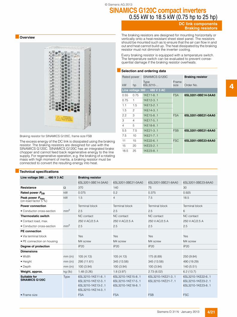
Braking resistor for SINAMICS G120C, frame size FSB
The excess energy of the DC link is dissipated using the braking resistor. The braking resistors are designed for use with the SINAMICS G120C. SINAMICS G120C has an integrated brake chopper and cannot feed back regenerative energy to the line supply. For regenerative operation, e.g. the braking of a rotating mass with high moment of inertia, a braking resistor must be connected to convert the resulting energy into heat.
The braking resistors are designed for mounting horizontally or vertically onto a heat-resistant sheet steel panel. The resistors should be mounted such as to ensure that the air can flow in and out and heat cannot build up. The heat dissipated by the braking resistor must not diminish the inverter cooling.
Every braking resistor is equipped with a temperature switch. The temperature switch can be evaluated to prevent conse-quential damage if the braking resistor overheats.
■ Selection and ordering data
■ Technical specifications
Rated power SINAMICS G120C Braking resistor
kW hpType6SL3210-...
Frame size Order No.
Line voltage 380 … 480 V 3 AC
0.55 0.75 1KE11-8..1 FSA 6SL3201-0BE14-3AA0
0.75 1 1KE12-3..1
1.1 1.5 1KE13-2..1
1.5 2 1KE14-3..1
2.2 3 1KE15-8..1 FSA 6SL3201-0BE21-0AA0
3 4 1KE17-5..1
4 5 1KE18-8..1
5.5 7.5 1KE21-3..1 FSB 6SL3201-0BE21-8AA0
7.5 10 1KE21-7..1
11 15 1KE22-6..1 FSC 6SL3201-0BE23-8AA0
15 20 1KE23-2..1
18.5 25 1KE23-8..1
Line voltage 380 … 480 V 3 AC Braking resistor
6SL3201-0BE14-3AA0 6SL3201-0BE21-0AA0 6SL3201-0BE21-8AA0 6SL3201-0BE23-8AA0
Resistance Ω 370 140 75 30
Rated power PDB kW 0.075 0.2 0.375 0.925
Peak power Pmax(on-load factor 5 %)
kW 1.5 4 7.5 18.5
Power connection Terminal block Terminal block Terminal block Terminal block
• Conductor cross-section mm2 2.5 2.5 2.5 6
Thermostatic switch NC contact NC contact NC contact NC contact
• Contact load, max. 250 V AC/2.5 A 250 V AC/2.5 A 250 V AC/2.5 A 250 V AC/2.5 A
• Conductor cross-section mm2 2.5 2.5 2.5 2.5
PE connection
• Via terminal block Yes Yes Yes Yes
• PE connection on housing M4 screw M4 screw M4 screw M4 screw
Degree of protection IP20 IP20 IP20 IP20
Dimensions
• Width mm (in) 105 (4.13) 105 (4.13) 175 (6.89) 250 (9.84)
• Height mm (in) 295 (11.61) 345 (13.58) 345 (13.58) 490 (19.29)
• Depth mm (in) 100 (3.94) 100 (3.94) 100 (3.94) 140 (5.51)
Weight, approx. kg (lb) 1.48 (3.26) 1.8 (3.97) 2.73 (6.02) 6.2 (13.7)
Suitable for SINAMICS G120C
Type 6SL3210-1KE11-8..16SL3210-1KE12-3..16SL3210-1KE13-2..16SL3210-1KE14-3..1
6SL3210-1KE15-8..16SL3210-1KE17-5..16SL3210-1KE18-8..1
6SL3210-1KE21-3..16SL3210-1KE21-7..1
6SL3210-1KE22-6..16SL3210-1KE23-2..16SL3210-1KE23-8..1
• Frame size FSA FSA FSB FSC
© Siemens AG 2013
SINAMICS G120C compact inverters0.55 kW to 18.5 kW (0.75 hp to 25 hp)Supplementary system componentsOperator panels
4/22 Siemens D 31 N · January 2013
4
■ Overview
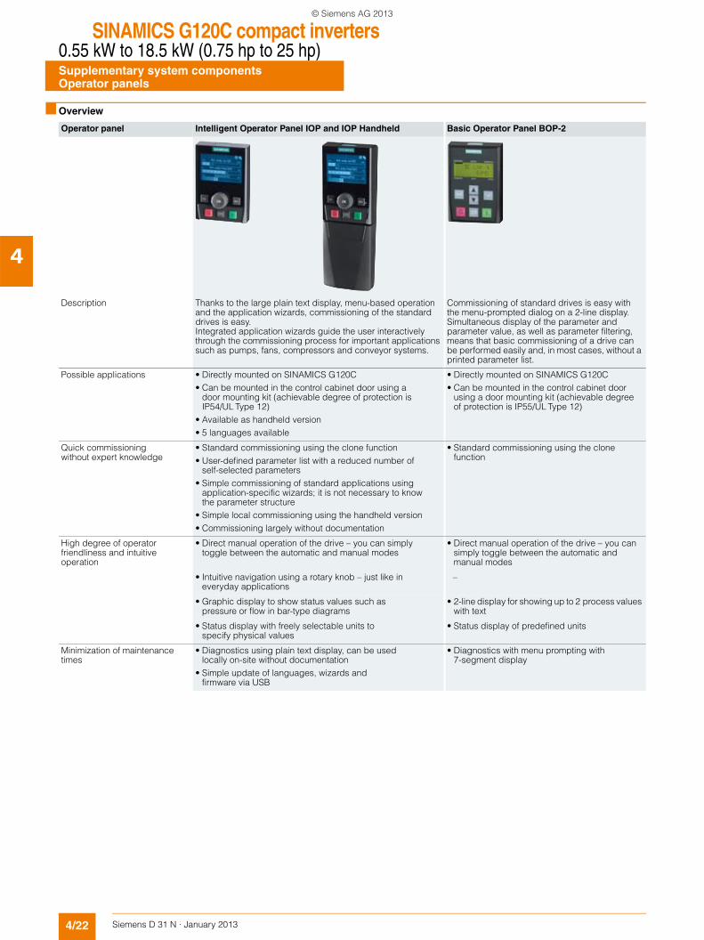
Operator panel Intelligent Operator Panel IOP and IOP Handheld Basic Operator Panel BOP-2
Description Thanks to the large plain text display, menu-based operation and the application wizards, commissioning of the standard drives is easy. Integrated application wizards guide the user interactively through the commissioning process for important applications such as pumps, fans, compressors and conveyor systems.
Commissioning of standard drives is easy with the menu-prompted dialog on a 2-line display. Simultaneous display of the parameter and parameter value, as well as parameter filtering, means that basic commissioning of a drive can be performed easily and, in most cases, without a printed parameter list.
Possible applications • Directly mounted on SINAMICS G120C• Can be mounted in the control cabinet door using a
door mounting kit (achievable degree of protection is IP54/UL Type 12)
• Available as handheld version• 5 languages available
• Directly mounted on SINAMICS G120C• Can be mounted in the control cabinet door
using a door mounting kit (achievable degree of protection is IP55/UL Type 12)
Quick commissioning without expert knowledge
• Standard commissioning using the clone function• User-defined parameter list with a reduced number of
self-selected parameters• Simple commissioning of standard applications using
application-specific wizards; it is not necessary to know the parameter structure
• Simple local commissioning using the handheld version• Commissioning largely without documentation
• Standard commissioning using the clone function
High degree of operator friendliness and intuitive operation
• Direct manual operation of the drive – you can simply toggle between the automatic and manual modes
• Direct manual operation of the drive – you can simply toggle between the automatic and manual modes
• Intuitive navigation using a rotary knob – just like in everyday applications
–
• Graphic display to show status values such as pressure or flow in bar-type diagrams
• 2-line display for showing up to 2 process values with text
• Status display with freely selectable units to specify physical values
• Status display of predefined units
Minimization of maintenance times
• Diagnostics using plain text display, can be used locally on-site without documentation
• Simple update of languages, wizards and firmware via USB
• Diagnostics with menu prompting with 7-segment display
© Siemens AG 2013
SINAMICS G120C compact inverters0.55 kW to 18.5 kW (0.75 hp to 25 hp)
Supplementary system componentsIntelligent Operator Panel IOP
4/23Siemens D 31 N · January 2013
4
■ Overview
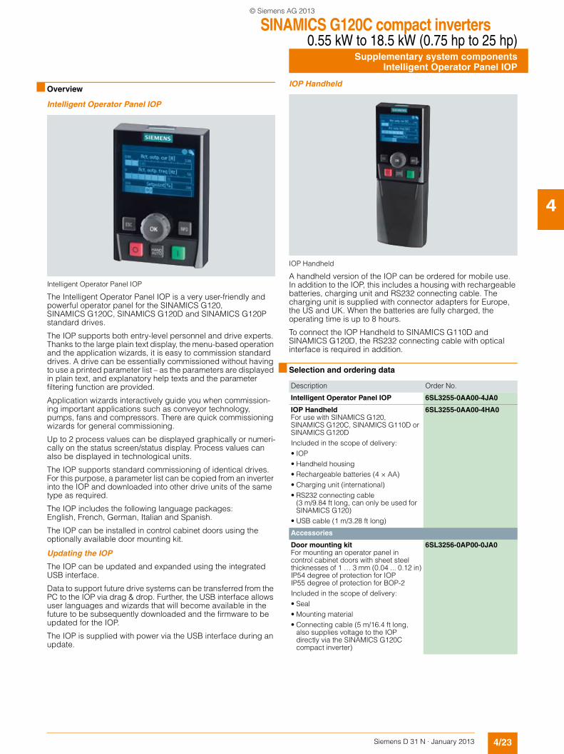
Intelligent Operator Panel IOP
Intelligent Operator Panel IOP
The Intelligent Operator Panel IOP is a very user-friendly and powerful operator panel for the SINAMICS G120, SINAMICS G120C, SINAMICS G120D and SINAMICS G120P standard drives.
The IOP supports both entry-level personnel and drive experts. Thanks to the large plain text display, the menu-based operation and the application wizards, it is easy to commission standard drives. A drive can be essentially commissioned without having to use a printed parameter list – as the parameters are displayed in plain text, and explanatory help texts and the parameter filtering function are provided.
Application wizards interactively guide you when commission-ing important applications such as conveyor technology, pumps, fans and compressors. There are quick commissioning wizards for general commissioning.
Up to 2 process values can be displayed graphically or numeri-cally on the status screen/status display. Process values can also be displayed in technological units.
The IOP supports standard commissioning of identical drives. For this purpose, a parameter list can be copied from an inverter into the IOP and downloaded into other drive units of the same type as required.
The IOP includes the following language packages: English, French, German, Italian and Spanish.
The IOP can be installed in control cabinet doors using the optionally available door mounting kit.
Updating the IOP
The IOP can be updated and expanded using the integrated USB interface.
Data to support future drive systems can be transferred from the PC to the IOP via drag & drop. Further, the USB interface allows user languages and wizards that will become available in the future to be subsequently downloaded and the firmware to be updated for the IOP.
The IOP is supplied with power via the USB interface during an update.
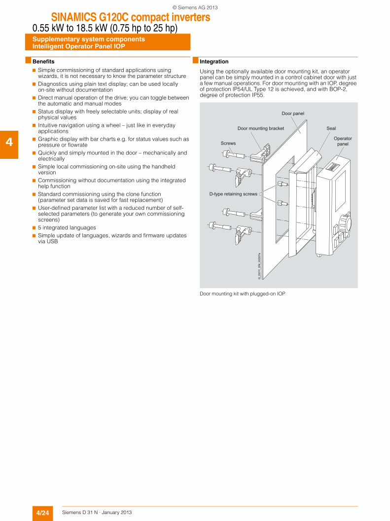
IOP Handheld
IOP Handheld
A handheld version of the IOP can be ordered for mobile use. In addition to the IOP, this includes a housing with rechargeable batteries, charging unit and RS232 connecting cable. The charging unit is supplied with connector adapters for Europe, the US and UK. When the batteries are fully charged, the operating time is up to 8 hours.
To connect the IOP Handheld to SINAMICS G110D and SINAMICS G120D, the RS232 connecting cable with optical interface is required in addition.
■ Selection and ordering data
Description Order No.
Intelligent Operator Panel IOP 6SL3255-0AA00-4JA0
IOP HandheldFor use with SINAMICS G120, SINAMICS G120C, SINAMICS G110D or SINAMICS G120DIncluded in the scope of delivery:• IOP• Handheld housing• Rechargeable batteries (4 × AA)• Charging unit (international)• RS232 connecting cable
(3 m/9.84 ft long, can only be used for SINAMICS G120)
• USB cable (1 m/3.28 ft long)
6SL3255-0AA00-4HA0
Accessories
Door mounting kitFor mounting an operator panel in control cabinet doors with sheet steel thicknesses of 1 … 3 mm (0.04 ... 0.12 in)IP54 degree of protection for IOP IP55 degree of protection for BOP-2Included in the scope of delivery:• Seal• Mounting material• Connecting cable (5 m/16.4 ft long,
also supplies voltage to the IOP directly via the SINAMICS G120C compact inverter)
6SL3256-0AP00-0JA0
© Siemens AG 2013
SINAMICS G120C compact inverters0.55 kW to 18.5 kW (0.75 hp to 25 hp)Supplementary system componentsIntelligent Operator Panel IOP
4/24 Siemens D 31 N · January 2013
4
■ Benefits
7 Simple commissioning of standard applications using wizards, it is not necessary to know the parameter structure
7 Diagnostics using plain text display; can be used locally on-site without documentation
7 Direct manual operation of the drive; you can toggle between the automatic and manual modes
7 Status display with freely selectable units; display of real physical values
7 Intuitive navigation using a wheel – just like in everyday applications
7 Graphic display with bar charts e.g. for status values such as pressure or flowrate
7 Quickly and simply mounted in the door – mechanically and electrically
7 Simple local commissioning on-site using the handheld version
7 Commissioning without documentation using the integrated help function
7 Standard commissioning using the clone function (parameter set data is saved for fast replacement)
7 User-defined parameter list with a reduced number of self-selected parameters (to generate your own commissioning screens)
7 5 integrated languages7 Simple update of languages, wizards and firmware updates
via USB
■ Integration
Using the optionally available door mounting kit, an operator panel can be simply mounted in a control cabinet door with just a few manual operations. For door mounting with an IOP, degree of protection IP54/UL Type 12 is achieved, and with BOP-2, degree of protection IP55.
Door mounting kit with plugged-on IOP
G_D
011_
EN
_002
07a
Screws
Door mounting bracket Seal
Door panel
D-type retaining screws
Operator panel
© Siemens AG 2013
SINAMICS G120C compact inverters0.55 kW to 18.5 kW (0.75 hp to 25 hp)
Supplementary system componentsBasic Operator Panel BOP-2
4/25Siemens D 31 N · January 2013
4
■ Overview
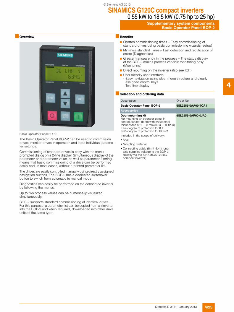
Basic Operator Panel BOP-2
The Basic Operator Panel BOP-2 can be used to commission drives, monitor drives in operation and input individual parame-ter settings.
Commissioning of standard drives is easy with the menu-prompted dialog on a 2-line display. Simultaneous display of the parameter and parameter value, as well as parameter filtering, means that basic commissioning of a drive can be performed easily and, in most cases, without a printed parameter list.
The drives are easily controlled manually using directly assigned navigation buttons. The BOP-2 has a dedicated switchover button to switch from automatic to manual mode.
Diagnostics can easily be performed on the connected inverter by following the menus.
Up to two process values can be numerically visualized simultaneously.
BOP-2 supports standard commissioning of identical drives. For this purpose, a parameter list can be copied from an inverter into the BOP-2 and when required, downloaded into other drive units of the same type.
■ Benefits
7 Shorten commissioning times – Easy commissioning of standard drives using basic commissioning wizards (setup)
7 Minimize standstill times – Fast detection and rectification of errors (Diagnostics)
7 Greater transparency in the process – The status display of the BOP-2 makes process variable monitoring easy (Monitoring)
7 Direct mounting on the inverter (also see IOP)7 User-friendly user interface:
- Easy navigation using clear menu structure and clearly assigned control keys
- Two-line display
■ Selection and ordering data
Description Order No.
Basic Operator Panel BOP-2 6SL3255-0AA00-4CA1
Accessories
Door mounting kitFor mounting an operator panel in control cabinet doors with sheet steel thicknesses of 1 … 3 mm (0.04 ... 0.12 in)IP54 degree of protection for IOPIP55 degree of protection for BOP-2Included in the scope of delivery:• Seal• Mounting material• Connecting cable (5 m/16.4 ft long,
also supplies voltage to the BOP-2 directly via the SINAMICS G120C compact inverter)
6SL3256-0AP00-0JA0
© Siemens AG 2013
SINAMICS G120C compact inverters0.55 kW to 18.5 kW (0.75 hp to 25 hp)Supplementary system componentsMemory cards
4/26 Siemens D 31 N · January 2013
4
■ Overview
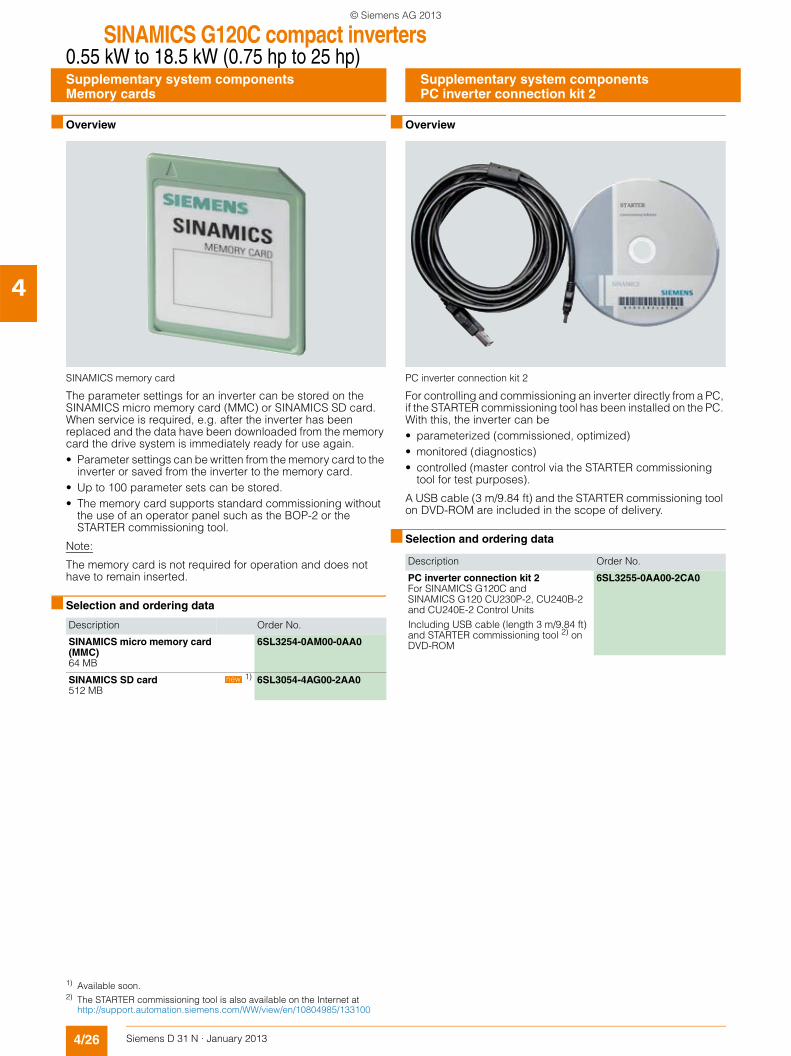
SINAMICS memory card
The parameter settings for an inverter can be stored on the SINAMICS micro memory card (MMC) or SINAMICS SD card. When service is required, e.g. after the inverter has been replaced and the data have been downloaded from the memory card the drive system is immediately ready for use again.• Parameter settings can be written from the memory card to the
inverter or saved from the inverter to the memory card.• Up to 100 parameter sets can be stored.• The memory card supports standard commissioning without
the use of an operator panel such as the BOP-2 or the STARTER commissioning tool.
Note:
The memory card is not required for operation and does not have to remain inserted.
■ Selection and ordering data
■ Overview
PC inverter connection kit 2
For controlling and commissioning an inverter directly from a PC, if the STARTER commissioning tool has been installed on the PC. With this, the inverter can be• parameterized (commissioned, optimized)• monitored (diagnostics)• controlled (master control via the STARTER commissioning
tool for test purposes).
A USB cable (3 m/9.84 ft) and the STARTER commissioning tool on DVD-ROM are included in the scope of delivery.
■ Selection and ordering data
Description Order No.
SINAMICS micro memory card (MMC)64 MB
6SL3254-0AM00-0AA0
SINAMICS SD card512 MB
1) 6SL3054-4AG00-2AA0new
Description Order No.
PC inverter connection kit 2For SINAMICS G120C and SINAMICS G120 CU230P-2, CU240B-2 and CU240E-2 Control Units Including USB cable (length 3 m/9.84 ft) and STARTER commissioning tool 2) on DVD-ROM
6SL3255-0AA00-2CA0
1) Available soon.2) The STARTER commissioning tool is also available on the Internet at
http://support.automation.siemens.com/WW/view/en/10804985/133100
Supplementary system componentsPC inverter connection kit 2
© Siemens AG 2013
SINAMICS G120C compact inverters0.55 kW to 18.5 kW (0.75 hp to 25 hp)
Spare parts
4/27Siemens D 31 N · January 2013
4
■ Overview
The following spare parts are available for SINAMICS G120C for service and maintenance work.
SINAMICS G120C shield plates
A set of shield plates is included in the scope of delivery for the motor and signal cables corresponding to the frame size of the SINAMICS G120C compact inverter, and can also be ordered as spare parts.
SINAMICS G120C spare parts kit
This kit comprises 5 sets of I/O terminals, 1 RS485 terminal, 2 sets of Control Unit doors (1 × PN and 1 × other communica-tion versions) and 1 blanking cover.
SINAMICS G120C connectors
A set of connectors for the line feeder cable, braking resistor and motor cable can be ordered corresponding to the frame size of the SINAMICS G120C compact inverter.
SINAMICS G120C roof-mounted fan
A roof-mounted fan (at the top of the device) comprising a pre-assembled unit with holder and fan can be ordered corresponding to the frame size of the SINAMICS G120C compact inverter.
SINAMICS G120C, frame size FSB, with integrated roof-mounted fan
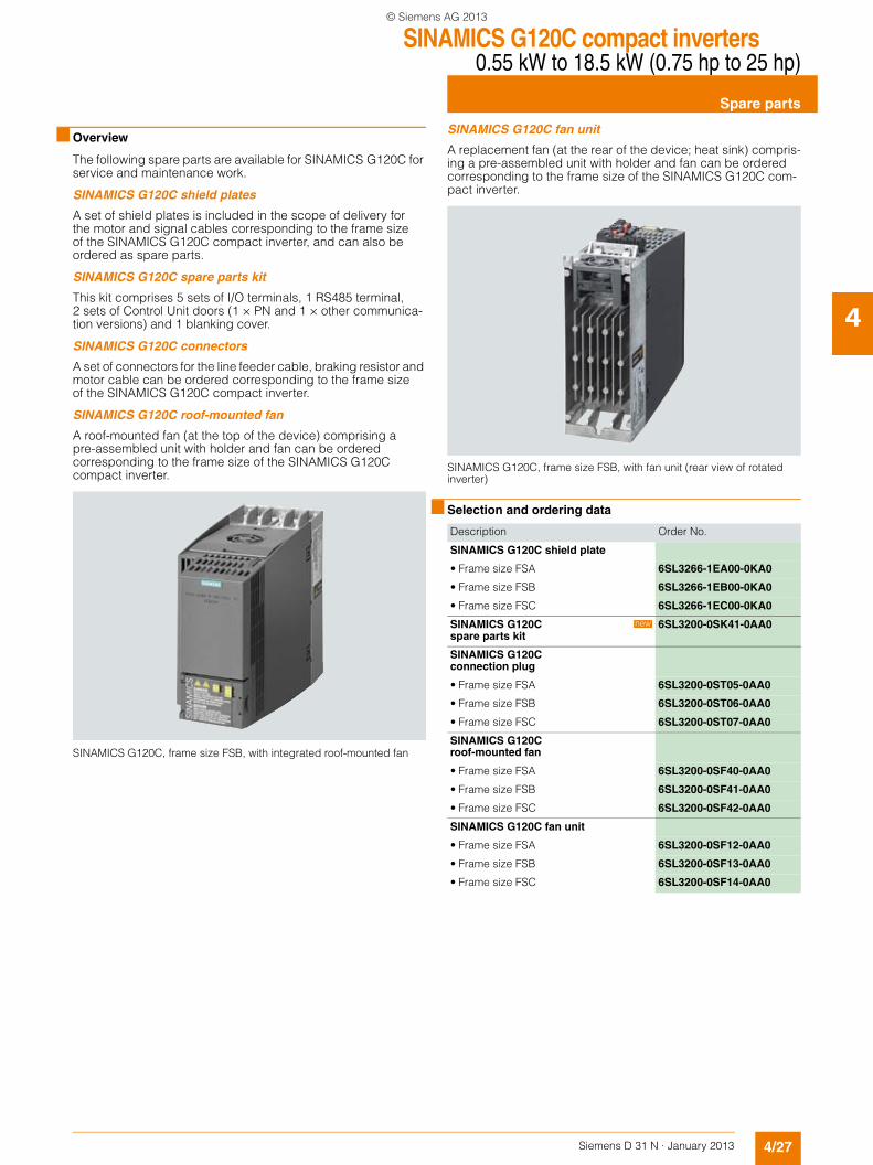
SINAMICS G120C fan unit
A replacement fan (at the rear of the device; heat sink) compris-ing a pre-assembled unit with holder and fan can be ordered corresponding to the frame size of the SINAMICS G120C com-pact inverter.
SINAMICS G120C, frame size FSB, with fan unit (rear view of rotated inverter)
■ Selection and ordering data
Description Order No.
SINAMICS G120C shield plate
• Frame size FSA 6SL3266-1EA00-0KA0
• Frame size FSB 6SL3266-1EB00-0KA0
• Frame size FSC 6SL3266-1EC00-0KA0
SINAMICS G120C spare parts kit
6SL3200-0SK41-0AA0
SINAMICS G120C connection plug
• Frame size FSA 6SL3200-0ST05-0AA0
• Frame size FSB 6SL3200-0ST06-0AA0
• Frame size FSC 6SL3200-0ST07-0AA0
SINAMICS G120C roof-mounted fan
• Frame size FSA 6SL3200-0SF40-0AA0
• Frame size FSB 6SL3200-0SF41-0AA0
• Frame size FSC 6SL3200-0SF42-0AA0
SINAMICS G120C fan unit
• Frame size FSA 6SL3200-0SF12-0AA0
• Frame size FSB 6SL3200-0SF13-0AA0
• Frame size FSC 6SL3200-0SF14-0AA0
new
© Siemens AG 2013

SINAMICS G120C compact inverters0.55 kW to 18.5 kW (0.75 hp to 25 hp)
Notes
4/28 Siemens D 31 N · January 2013
4
© Siemens AG 2013