Embed Size (px)
Citation preview
Siemens Energy & Automation, Inc. Installation and Service Instruction
SD39ACM-3 Rev: 4
September 2005
APACS+™ Advanced Control Module Plus (ACM+)
Trademarks ProcessSuite, QUADLOG, 4-mation, and APACS+ are trademarks of Siemens Energy & Automation, Inc.
Other names in this publication might be trademarks, the use of which by third parties for their own purposes may violate the rights of the registered holder.
Copyright Siemens Energy & Automation, Inc. 2005 All rights reserved
The reproduction, transmission or use of this document or its contents is not permitted without express written authority. Offenders will be liable for damages. All rights, including rights created by patent or registration of a utility model or design, are reserved. Siemens Energy & Automation, Inc. 1201 Sumneytown Pike P.O. Box 900 Spring House, PA 19477-0900
Disclaimer of Liability We have checked the contents of this manual for agreement with the hardware and software described. Since deviations cannot be precluded entirely, we cannot guarantee full agreement. However, the data in this manual is reviewed regularly and any necessary corrections included in subsequent editions. Suggestions for improvement are welcomed. ©Siemens Energy & Automation, Inc. 2005 Technical data subject to change.
SD39ACM-3 Contents
September 2005 i
Table of Contents
Section Title Page
1 Introduction....................................................................................................................1-1 1.1 Product Description ......................................................................................................1-1 1.1.1 LED Indicators.......................................................................................................1-3 1.1.2 Configuration .........................................................................................................1-3 1.1.3 Software Functions ................................................................................................1-4 1.1.4 Control Strategies...................................................................................................1-4 1.2 Product Support ............................................................................................................1-4 1.3 Related Literature .........................................................................................................1-6
2 Installation......................................................................................................................2-1 2.1 Hardware Identification................................................................................................2-1 2.1.1 ACM Transition Board ..........................................................................................2-2 2.2 Considerations and Preparations ..................................................................................2-2 2.2.1 EMC Directive Installation Considerations ...........................................................2-2 2.2.2 Preparations............................................................................................................2-3 2.3 Environmental Considerations .....................................................................................2-3 2.4 Equipment Delivery and Handling ...............................................................................2-5 2.4.1 Predelivery Test .....................................................................................................2-5 2.4.2 Factory Shipment ...................................................................................................2-5 2.4.3 Receipt of Shipment...............................................................................................2-5 2.4.4 Equipment Handling ..............................................................................................2-6 2.4.5 Equipment Storage.................................................................................................2-6 2.5 Mechanical Installation.................................................................................................2-6 2.5.1 ACM Transition Board Installation .......................................................................2-7 2.5.2 ACM+ Installation .................................................................................................2-8 2.5.2.1 Module Rack Mechanical Keying................................................................2-8 2.5.2.2 Module Installation ......................................................................................2-9 2.6 ELECTRICAL INSTALLATION..............................................................................2-11 2.6.1 Cable Connections ...............................................................................................2-12 2.6.1.1 Redundancy Cable......................................................................................2-12 2.6.1.2 Serial Port Cables .......................................................................................2-13 2.6.2 Switches ...............................................................................................................2-14 2.6.2.1 SECURITY ENABLE Switch Setting .......................................................2-14 2.6.2.2 NODE Switch Setting ................................................................................2-17 2.6.3 RAM Battery........................................................................................................2-19
3 Maintenance ...................................................................................................................3-1 3.1 Tool and Equipment Requirements ..............................................................................3-1 3.2 Preventive Maintenance ...............................................................................................3-1 3.2.1 Visual Inspection....................................................................................................3-1 3.2.2 Cleaning .................................................................................................................3-2 3.3 Troubleshooting............................................................................................................3-2 3.3.1 Typical ACM+ Error Codes...................................................................................3-2 3.3.2 Bezel LEDs ............................................................................................................3-6
Contents SD39ACM-3
ii September 2005
3.3.3 Diagnostic Port.......................................................................................................3-7 3.4 ACM+ Removal/Replacement .....................................................................................3-7 3.4.1 ACM+ Removal.....................................................................................................3-7 3.4.2 ACM+ Replacement ..............................................................................................3-8 3.4.3 Online Redundancy Cable Replacement................................................................3-9 3.5 Transition Board Removal/Replacement......................................................................3-9 3.5.1 Removal .................................................................................................................3-9 3.5.2 Replacement...........................................................................................................3-9 3.6 Component Replacement............................................................................................3-10 3.6.1 RAM Battery Replacement ..................................................................................3-10 3.7 Spare And Replacement Parts ....................................................................................3-11 3.8 Return of Equipment within North America ..............................................................3-12 3.8.1 Return of Equipment outside North America ......................................................3-12 3.9 Software Compatibility...............................................................................................3-12 3.10 Maintenance Records .................................................................................................3-13
4 Circuit Description ........................................................................................................4-1 4.1 ACM+ Functional Elements .........................................................................................4-1 4.2 Watchdog/Reset............................................................................................................4-1 4.3 BUS Timeout and BUS Arbitration..............................................................................4-2 4.4 RAM and ROM ............................................................................................................4-3 4.5 Serial Ports....................................................................................................................4-3 4.6 MODULBUS................................................................................................................4-3 4.7 IOBUS ..........................................................................................................................4-3 4.8 Small Computer System Interface (SCSI) and Redundancy ........................................4-4
5 Model Designation .........................................................................................................5-1 5.1 Accessories ...................................................................................................................5-1 5.2 Options .........................................................................................................................5-1
6 Specifications..................................................................................................................6-1 6.1 Module Specifications ..................................................................................................6-1 6.2 Environmental Specifications.......................................................................................6-2 6.3 Electrical Classification................................................................................................6-3 6.3.1 Approvals ...............................................................................................................6-3 6.3.2 CSA Hazardous Locations Precautions .................................................................6-3 6.4 Electromagnetic Compatibility (EMC).........................................................................6-5
SD39ACM-3 Contents
September 2005 iii
List of Tables
Table Title Page
Table 2–1 ACM+ Serial Ports 1 and 2 Pin Assignments ........................................................................2-13
Table 2–2 Determining ACM+’s Node Address ....................................................................................2-18
Table 3–1 Typical Error Codes.................................................................................................................3-3
Table 3–2 ACM+ Status LED Indications................................................................................................3-7
Table 5–1 ACM+ Accessories ..................................................................................................................5-1
Table 6–1 ACM+ Module Specifications .................................................................................................6-1
Table 6–2 Electromagnetic Compatibility (ECM) Specifications ............................................................6-2
Table 6–3 ACM+ Environmental Specifications......................................................................................6-2
Table 6–4 Agency Approvals ...................................................................................................................6-3
List of Illustrations
Figure Title Page
Figure 1–1 Advanced Control Module and Transition Board ..................................................................1-2
Figure 2–1 ACM Transition Board Mounting ..........................................................................................2-9
Figure 2–2 Module Keying Assignment and Installation .......................................................................2-11
Figure 2–3 Redundancy Cable Connection ............................................................................................2-13
Figure 2–4 SECURITY ENABLE Switch..............................................................................................2-16
Figure 4–1 ACM+ Block Diagram ...........................................................................................................4-2
Figure 5–1 Model Designation .................................................................................................................5-1
Significant Changes for Revision 4
Section Description
Preface (Conventions and Symbols)— new section
1.2 Product Support—contact information updated.
Contents SD39ACM-3
iv September 2005
2.6.1 Cable Connections—DANGER alert added
3 Maintenance—DANGER alert added
6.3.2 CSA Hazardous Locations Precautions—Warning added.
SD39ACM-3 Contents
September 2005 v
PREFACE
Conventions and Symbols
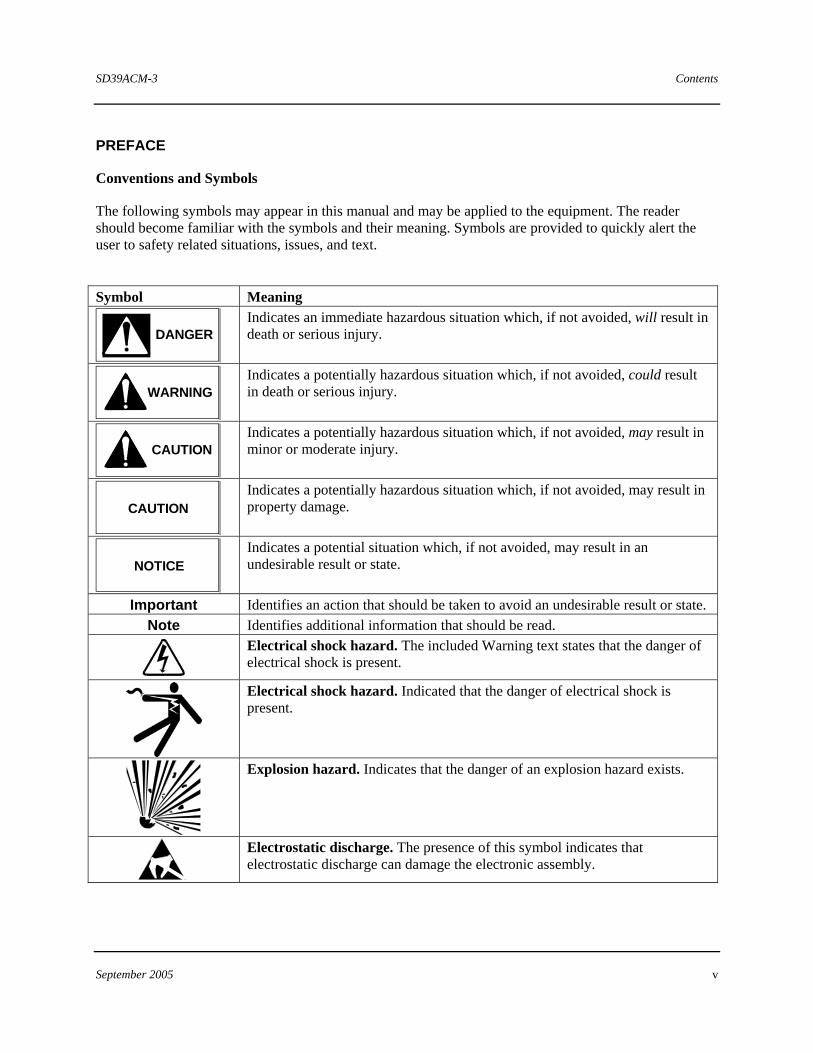
The following symbols may appear in this manual and may be applied to the equipment. The reader should become familiar with the symbols and their meaning. Symbols are provided to quickly alert the user to safety related situations, issues, and text.
Symbol Meaning
DANGER
Indicates an immediate hazardous situation which, if not avoided, will result in death or serious injury.
WARNING
Indicates a potentially hazardous situation which, if not avoided, could result in death or serious injury.
CAUTION
Indicates a potentially hazardous situation which, if not avoided, may result in minor or moderate injury.
CAUTION
Indicates a potentially hazardous situation which, if not avoided, may result in property damage.
NOTICE
Indicates a potential situation which, if not avoided, may result in an undesirable result or state.
Important Identifies an action that should be taken to avoid an undesirable result or state. Note Identifies additional information that should be read.
Electrical shock hazard. The included Warning text states that the danger of electrical shock is present.
Electrical shock hazard. Indicated that the danger of electrical shock is present.
Explosion hazard. Indicates that the danger of an explosion hazard exists.
Electrostatic discharge. The presence of this symbol indicates that electrostatic discharge can damage the electronic assembly.
Contents SD39ACM-3
vi September 2005
Qualified Persons
The described equipment should be installed, configured, operated, and serviced only by qualified persons thoroughly familiar with this publication. The current version, in Portable Document Format (PDF), is available at http://sitescape.sea.siemens.com/.
For the purpose of this publication and product labels, a qualified person is one who is familiar with the installation, construction, and operation of the equipment, and the involved hazards. In addition, he or she has the following qualifications:
• Is trained and authorized to energize, de-energize, clear, ground and tag circuits and equipment in accordance with established safety practices.
• Is trained in the proper care and use of protective equipment such as rubber gloves, hard hat, safety glasses or face shields, flash clothing, etc., in accordance with established safety practices.
• Is trained in rendering first aid.
Scope
This publication does not purport to cover all details or variations in equipment, nor to provide for every possible contingency to be met in connection with installation, operation, or maintenance. Should further information be desired or should particular problems arise which are not covered sufficiently for the purchaser’s purposes, the matter should be referred to one of the support groups listed in the Product Support section of this manual.
The contents of this manual shall not become part of or modify any prior or existing agreement, commitment or relationship. The sales contract contains the entire obligation of Siemens. The warranty contained in the contract between the parties is the sole warranty of Siemens. Any statements continued herein do not create new warranties or modify the existing warranty.
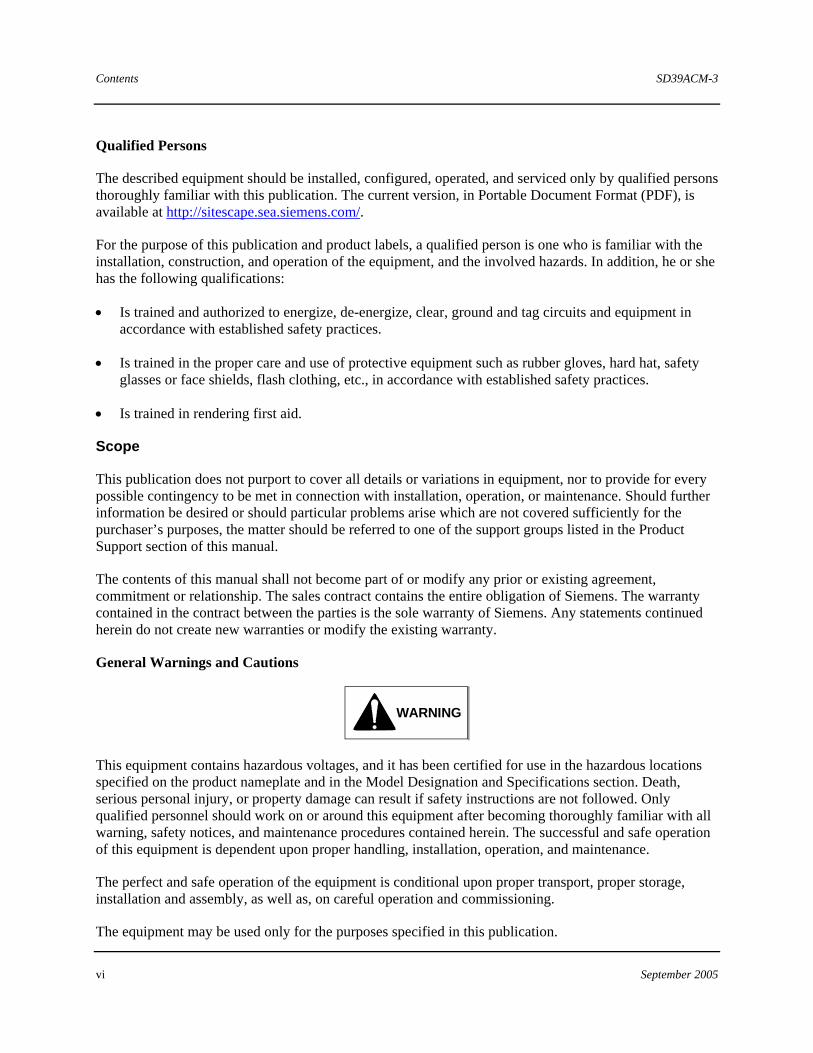
General Warnings and Cautions
WARNING
This equipment contains hazardous voltages, and it has been certified for use in the hazardous locations specified on the product nameplate and in the Model Designation and Specifications section. Death, serious personal injury, or property damage can result if safety instructions are not followed. Only qualified personnel should work on or around this equipment after becoming thoroughly familiar with all warning, safety notices, and maintenance procedures contained herein. The successful and safe operation of this equipment is dependent upon proper handling, installation, operation, and maintenance.
The perfect and safe operation of the equipment is conditional upon proper transport, proper storage, installation and assembly, as well as, on careful operation and commissioning.
The equipment may be used only for the purposes specified in this publication.
SD39ACM-3 Contents
September 2005 vii
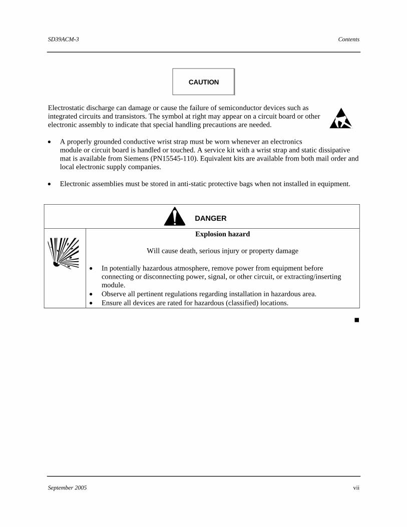
CAUTION
Electrostatic discharge can damage or cause the failure of semiconductor devices such as integrated circuits and transistors. The symbol at right may appear on a circuit board or other electronic assembly to indicate that special handling precautions are needed.
• A properly grounded conductive wrist strap must be worn whenever an electronics module or circuit board is handled or touched. A service kit with a wrist strap and static dissipative mat is available from Siemens (PN15545-110). Equivalent kits are available from both mail order and local electronic supply companies.
• Electronic assemblies must be stored in anti-static protective bags when not installed in equipment.
DANGER
Explosion hazard
Will cause death, serious injury or property damage • In potentially hazardous atmosphere, remove power from equipment before
connecting or disconnecting power, signal, or other circuit, or extracting/inserting module.
• Observe all pertinent regulations regarding installation in hazardous area. • Ensure all devices are rated for hazardous (classified) locations.

SD39ACM-3 Introduction
September 2005 1-1
1 Introduction
This Instruction provides installation and service information for the following Advanced Control Module Plus (ACM+) hardware:
• Model 39ACM24BEN (68040 CPU, 4MB SRAM) P/N 16139-215 • Model 39ACM28AEN (68040 CPU, 8MB SRAM) P/N 16139-218 • ACM Transition Board with Node Switch P/N 16147-51
This Instruction is divided into six major sections.
• Section 1, Introduction – Contains product description, product support, and lists related literature.
• Section 2, Installation – Describes environmental considerations and mechanical and electrical installation.
• Section 3, Maintenance – Consists of preventive maintenance, troubleshooting, assembly replacement procedures, and spare and replacement parts suggestions.
• Section 4, Circuit Description – Contains a brief system level description of the ACM.
• Section 5, Model Designation – Provides model designation and lists of accessories and options.
• Section 6, Specifications – Consists of mechanical, electrical, and environmental specifications.
1.1 Product Description
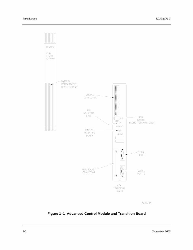
The microprocessor-based Advanced Control Module Plus (ACM+) is a key element of the APACS+� Advanced Controller. An ACM+ can communicate with any APACS+ I/O modules via the IOBUS or communicate with control, computer, and communication modules via the MODULBUS. Figure 1-1 illustrates the ACM+ and its associated transition boards.
The ACM+ occupies a single module rack slot. The top connector at the rear of the module mates with a connector on the rack back plane. This connector provides power bus, IOBUS, and MODULBUS access. The bottom connector mates with an ACM transition board to access the serial ports and redundancy connector. Each installed ACM+ requires a transition board to operate, which includes two RS-232C serial ports for serial communications applications. Also provided is a redundancy connector, which permits two ACM+s to operate in a redundant configuration.
Introduction SD39ACM-3
1-2 September 2005
Figure 1–1 Advanced Control Module and Transition Board
SD39ACM-3 Introduction
September 2005 1-3
In comparison to the APACS+ ACM module, the ACM+ contains 1MB of FLASH EEPROM memory for non-volatile storage of the operating system software, whereas the ACM stored the operating system software in RAM. FLASH EEPROM storage protects the operating system software from accidental modification and/or corruption. The ACM+ also frees approximately 500KB of RAM for the application specific configuration.
The ACM+ runs operating system software from its Program flash, instead of from SRAM. However, the configuration still resides in SRAM. As such, it is no longer possible to erase the ACM operating software by pulling the module out of the rack and removing the battery. The module must be re-initialized via 4-mation or cross-loaded to load new operating system software.
1.1.1 LED Indicators
The ACM+’s LEDs support local troubleshooting without an operator interface. The module includes three LEDs, which indicate the following module statuses: • Module OK • Module Faulted • Module Unconfigured • Module Failed
• Module Active • Module Inactive • Security Enabled • Security Disabled
See Table 3-2 in section 3.0, Maintenance, of this Guide for detailed description of the ACM+ status LED indications.
1.1.2 Configuration
The ACM+ is configured using the ProcessSuite™ 4-mation™ Configuration software. 4-mation allows a control strategy to be defined using any mix of four languages, which are based on the IEC specification for programmable controllers (IEC 1131-3). These languages are function blocks, ladder logic, sequential function charts, and structured text. These languages allow a configuration to be created using the tool(s) most effective for each application.
4-mation is also used to configure an ACM+’s I/O, as well as modules within an APACS+ system. A backup copy of the I/O module’s configuration is maintained by the ACM+ to allow automatic configuration of an I/O module when it is inserted into a module rack.
An ACM+’s configuration can be created off-line and transferred to the module, or a configuration can be created within an on-line ACM+ during the initial design phase. On-line configuration is possible because all of the information needed to configure an ACM+ is stored in its database, thus eliminating the need to have a disk-based master database for viewing or editing a configuration. Several different restriction levels are available.
The ACM+’s security can be programmed so no unauthorized or inadvertent changes are made to a configuration. When this security feature is activated, a configuration can be opened in �read/write� mode only, ensuring that no further changes are made to the control strategy.
Introduction SD39ACM-3
1-4 September 2005
The ACM+ also includes features to simplify start-up should operation be disrupted. An ACM+�s configuration is battery-backed so that the configuration for an ACM+ and its I/O is maintained when power is lost. Also, variables within an ACM+ can be assigned warm start and cold start values. When power is lost, the ACM+’s real-time clock continues to run so that warm start and cold start states can be determined and acted upon once power is restored.
1.1.3 Software Functions
The ACM+ can be used in conjunction with APACS+ I/O modules to control either a continuous or batch process. ACM+ software is able to execute Function Block Diagrams, Ladder Diagrams, Sequential Function Charts, and Structured Text.
1.1.4 Control Strategies
The ACM+ can be used in conjunction with APACS+ I/O modules to build DCS style and/or PLC style systems. It can also be used by itself (or with I/O modules) to supervise the operation of other APACS+ control modules, as required by the process strategy.
1.2 Product Support
Our Technical Support Centers (TSC) offer a variety of technical support services that are designed to assist you with Siemens products and systems. Our support engineers have experience with troubleshooting, development, system startup, and system test. They will help you to solve your issues in an efficient and professional manner.
Customers in North America can contact Siemens Technical Support Center at 1-800-333-7421, on the web at: http://support.automation.siemens.com, or by e-mail: [email protected]
Customers outside North America can contact their local Siemens subsidiary; addresses and telephone numbers are listed on the Internet at the web site: http://support.automation.siemens.com.
When contacting Siemens, customers will be asked to provide site-contact information (name, address, and phone number), the product involved and detailed information regarding the nature of the issue.
Product documentation is now located in the Library forum of the Process Automation User Connection at: http://sitescape.sea.siemens.com/. The Process Automation User Connection is a secure site. Registration is open to all verified users of Siemens process automation systems. If you are not already, and would like to become a member, please visit our Process Automation User Connection web page at: http://www.sea.siemens.com/process/support/papauc.html
Contained within the Process Automation User Connection is the APACS+/QUADLOG Secure Site at: http://sitescape.sea.siemens.com/forum/aca-1/dispatch.cgi/f.apacsquadlo forum. This site is only open to customers with an active service agreement. It contains all service manuals, service memos, service notes, configuration manuals, etc. for the APACS+ and QUADLOG family of products. If you are experiencing technical difficulties with the site, please contact SiteScape technical support at: toll free 1-877-234-1122 (US) or 1-513-336-1474.
SD39ACM-3 Introduction
September 2005 1-5
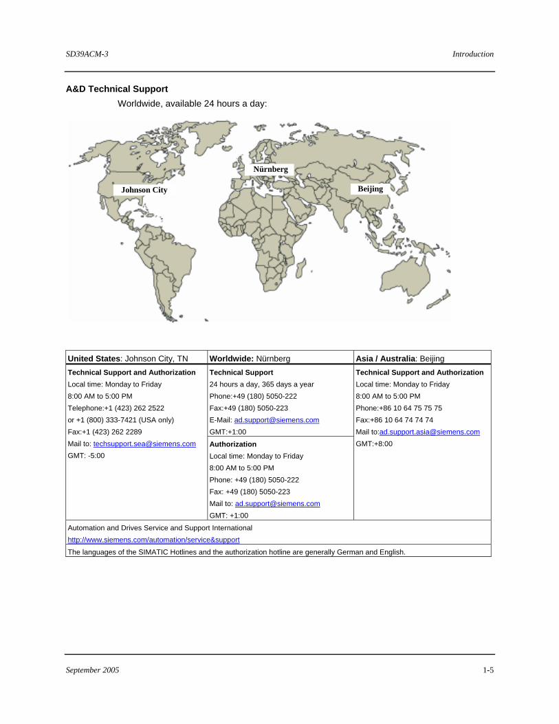
A&D Technical Support Worldwide, available 24 hours a day:
Beijing
Nürnberg
Johnson City
United States: Johnson City, TN Worldwide: Nürnberg Asia / Australia: Beijing Technical Support 24 hours a day, 365 days a year Phone:+49 (180) 5050-222 Fax:+49 (180) 5050-223 E-Mail: [email protected] GMT:+1:00
Technical Support and Authorization Local time: Monday to Friday 8:00 AM to 5:00 PM Telephone:+1 (423) 262 2522 or +1 (800) 333-7421 (USA only) Fax:+1 (423) 262 2289 Mail to: [email protected] GMT: -5:00
Authorization Local time: Monday to Friday 8:00 AM to 5:00 PM Phone: +49 (180) 5050-222 Fax: +49 (180) 5050-223 Mail to: [email protected] GMT: +1:00
Technical Support and Authorization Local time: Monday to Friday 8:00 AM to 5:00 PM Phone:+86 10 64 75 75 75 Fax:+86 10 64 74 74 74 Mail to:[email protected] GMT:+8:00
Automation and Drives Service and Support International http://www.siemens.com/automation/service&support
The languages of the SIMATIC Hotlines and the authorization hotline are generally German and English.
SD39ACM-3
1-6 September 2005
1.3 Related Literature
The following literature should be available when performing an ACM+ installation.
• APACS+ MODULRAC Installation and Service Instruction (Document # SD39MODULRAC-1)
• APACS+ SIXRAC Installation and Service Instruction (Document # SD39SIXRAC-1)
• APACS+ MODULPAC 1000 Installation and Service Instruction (Document # SD39MODULPAC-1)
• APACS+ MODULPAC 2000 Installation and Service Instruction (Document # SD39MODULPAC-2)
SD39ACM-3 Installation
September 2005 2-1
2 Installation
This section describes the installation of the ACM+ and the ACM Transition Board. Read this entire section before starting an installation.
IMPORTANT NOTE
ACM+ installation should be performed in accordance with the National Electrical Code (NEC) and other applicable construction and electrical codes.
2.1 Hardware Identification
2.1.1 Advanced Control Module Plus (ACM+)
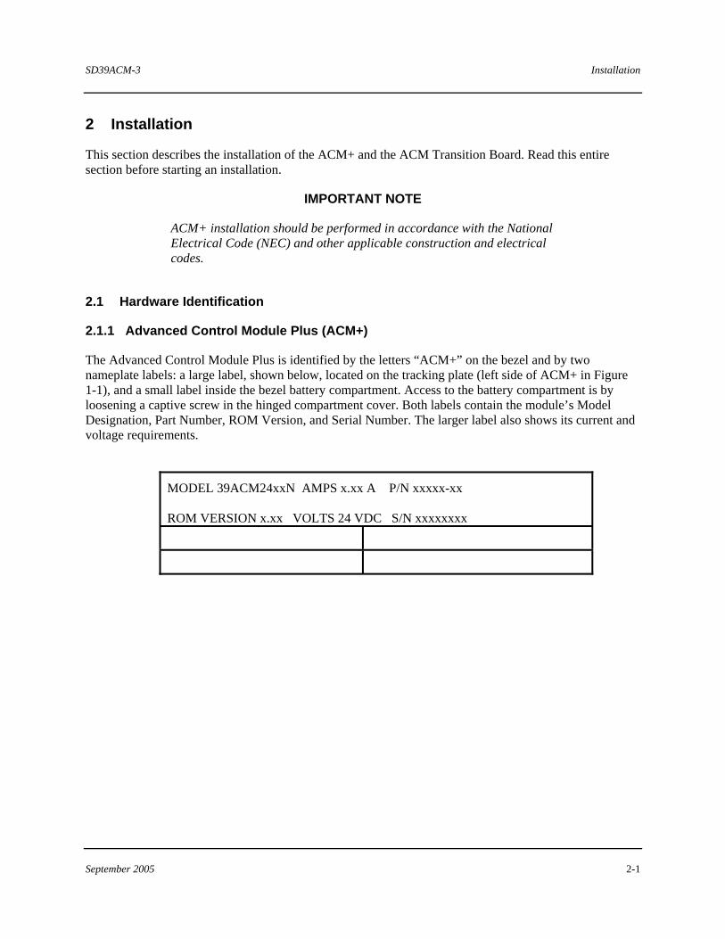
The Advanced Control Module Plus is identified by the letters “ACM+” on the bezel and by two nameplate labels: a large label, shown below, located on the tracking plate (left side of ACM+ in Figure 1-1), and a small label inside the bezel battery compartment. Access to the battery compartment is by loosening a captive screw in the hinged compartment cover. Both labels contain the module’s Model Designation, Part Number, ROM Version, and Serial Number. The larger label also shows its current and voltage requirements.
MODEL 39ACM24xxN AMPS x.xx A P/N xxxxx-xx ROM VERSION x.xx VOLTS 24 VDC S/N xxxxxxxx
Installation SD39ACM-3
2-2 September 2005
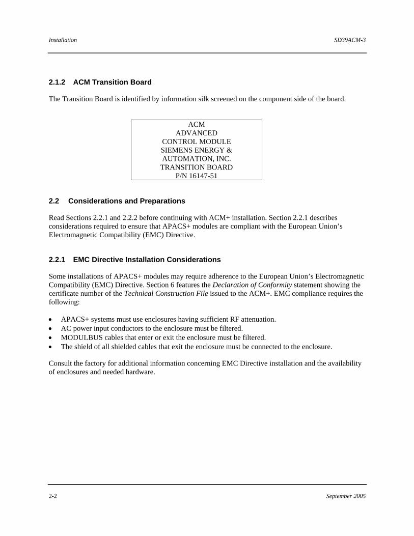
2.1.2 ACM Transition Board
The Transition Board is identified by information silk screened on the component side of the board.
ACM
ADVANCED CONTROL MODULE SIEMENS ENERGY & AUTOMATION, INC.
TRANSITION BOARD P/N 16147-51
2.2 Considerations and Preparations
Read Sections 2.2.1 and 2.2.2 before continuing with ACM+ installation. Section 2.2.1 describes considerations required to ensure that APACS+ modules are compliant with the European Union’s Electromagnetic Compatibility (EMC) Directive.
2.2.1 EMC Directive Installation Considerations
Some installations of APACS+ modules may require adherence to the European Union’s Electromagnetic Compatibility (EMC) Directive. Section 6 features the Declaration of Conformity statement showing the certificate number of the Technical Construction File issued to the ACM+. EMC compliance requires the following:
• APACS+ systems must use enclosures having sufficient RF attenuation. • AC power input conductors to the enclosure must be filtered. • MODULBUS cables that enter or exit the enclosure must be filtered. • The shield of all shielded cables that exit the enclosure must be connected to the enclosure.
Consult the factory for additional information concerning EMC Directive installation and the availability of enclosures and needed hardware.
SD39ACM-3 Installation
September 2005 2-3
2.2.2 Preparations
1. Install SIXRACs or MODULRACs with Local Termination Panels (for local termination only) in MODULPACs or cabinets where ACM+s are to be installed. The ACM+s should not be installed in their racks at this time. However, the rack slots numbers for ACM+s should be known.
2. Note that in determining a rack slot for an ACM+:
• Only I/O modules installed in slots to the right of an ACM+ (higher slot numbers or in next IOBUS-connected rack) are slaved to that ACM+.
• Only an empty slot, Bus Continuation Module (BCM), or Bus Diverter Module (BDM) may be between an ACM+ and any of its slaved I/O modules. Empty slots are not permitted on the IOBUS of rack-to-rack redundant systems.
• Terminate the IOBUS before assigning slot numbers for the next ACM+ and its I/O modules.
3. Determine whether redundant ACM+s will be installed. ACM+ hardware and software provides for module-to-module and rack-to-rack redundancy as described as follows:
• Module-to-Module Redundancy – Two ACM+s are mounted in adjacent ascending odd-even (e.g. 1-2, 3-4, 7-8) slots in a rack sharing common I/O modules. One ACM+ operates while the other is in standby and can instantly assume control should a failure occur in the operating module. The operating ACM+ accesses I/O modules in the rack via IOBUS. Both ACM+s communicate over a dedicated redundancy cable.
• Rack-to-Rack Redundancy – Two ACM+s are mounted in two module racks that are complete duplicates. One rack is operating, the other is in standby and can instantly assume control should a failure occur in the operating rack. They communicate over a dedicated redundancy cable.
A transition board NODE Switch provides for the setting of a node address for each ACM+ when the controller’s MODULBUS is not connected via MBX module to MODULNET.
CAUTION
Redundant ACM+’s must be identical. Therefore, the ACM+ model number, part number, and ROM version must be identical.
2.3 Environmental Considerations
Many industrial environments create severe operating conditions. The conditions at each ACM+ location must be within the specifications stated in Section 6.2, Environmental Specifications, of this Guide.
Installation SD39ACM-3
2-4 September 2005
CAUTION
Exceeding specified operating temperature limits can adversely affect performance and cause damage. Air temperature should be periodically checked to ensure that this specification is not exceeded.
To ensure reliable data communications, it would be prudent to locate APACS+ module enclosures as far as possible from sources of interference such as high current electrical equipment, which emit strong electromagnetic fields and switching transients.
Industrial environments often contain particulate, liquid, and gaseous contaminants. Particulate matter, usually dust and dirt, is abrasive and can cause intermittent contact in connectors associated with circuit assemblies. A layer of dust on circuit boards will interfere with semiconductor heat dissipation. Liquid and gaseous contaminants can have a corrosive effect on metal, rubber, plastic and circuit board components. Extended exposure to this environment may result in equipment malfunction.
To reduce contaminant related equipment malfunctions:
• Identify contaminants and implement methods to reduce their presence.
• When cleaning equipment and surrounding area, especially the floor, either vacuum away all dust and dirt or use a dampened rag or mop.
• Clean or replace all air conditioning filters, room air filters, and equipment filters regularly.
• Inform personnel with access to APACS+ modules of the need for site cleanliness.
SD39ACM-3 Installation
September 2005 2-5
2.4 Equipment Delivery and Handling
The following subsections provide information of interest to shipping, receiving, and warehouse personnel.
2.4.1 Predelivery Test
An ACM+ that will be installed by the user is fully tested and inspected to ensure proper operation. If the ACM+ is ordered factory installed in a MODULPAC or other enclosure, the ACM+ is tested as part of the APACS+ system and inspected to ensure proper operation.
2.4.2 Factory Shipment
ACM+s to be installed by the user are placed in static shielding bags and packaged for shipment. Accessories are packaged separately.
If the ACM+ is ordered factory installed in a MODULPAC or other enclosure, the enclosure is bolted to a pallet and wrapped for protection during shipment.
2.4.3 Receipt of Shipment
All cartons should be inspected at the time of their delivery for possible external damage. Any visible damage should be immediately recorded on the carrier’s copy of the delivery slip. Each carton should be carefully unpacked and its contents checked against the enclosed packing list. At the same time, each item should be inspected for hidden damage that may or may not have been accompanied by exterior carton damage.
If it is found that some items have been damaged or are missing, notify Siemens immediately and provide full details. In addition, damages must be reported to the carrier with a request for their on-site inspection of the damaged item and its shipping carton.
Installation SD39ACM-3
2-6 September 2005
2.4.4 Equipment Handling
The ACM+ is completely enclosed and may be safely handled without undertaking special ESD (electrostatic discharge) handling procedures provided the battery compartment door is closed and secured. DO NOT touch the connector pins on the back of the module. Handle the module carefully and do not subject it to excessive shock or vibration.
CAUTION
A grounded wrist strap must be used to provide ESD protection whenever the battery compartment door is opened to access the backup battery or Security Enable switch.
2.4.5 Equipment Storage
The storage temperature and humidity parameters of Section 6.2 must be met to properly store an ACM+.
When the ACM+ is not powered in storage, the backup battery must be disabled. An ACM+ removed from storage for use must be prepared as described in Section 2.6.3.
IMPORTANT
Prior to applying power to the ACM+, engage the backup battery. A weak or disconnected battery will cause the ACM+ to reset.
2.5 Mechanical Installation
This section provides detailed information on the installation of transition boards and the module.
SD39ACM-3 Installation
September 2005 2-7
2.5.1 ACM Transition Board Installation
Mount the ACM Transition Board (Figure 1-1) at the MODULRAC or SIXRAC slot location of its companion ACM+.
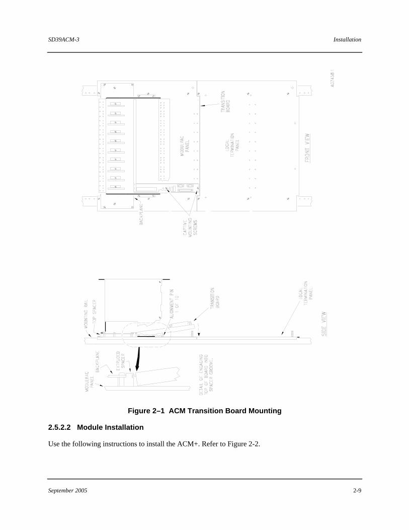
Refer to Figure 2-1 and the following mounting instructions:
1. Consult user documentation and note the slot location assigned to the ACM+(s).
2. Note the following on a MODULRAC/SIXRAC and on the transition board:
• At the rear of the rack, locate and identify the extruded spacer to which the lower edge of the backplane is mounted. Note that the bottom of the extruded spacer is grooved. The top edge of the transition board will rest in this groove.
• Identify alignment pins located below the rack’s frame that span the width of the rack. The left-most pin corresponds to rack slot #1. One of these pins will engage a hole located on the termination board above the SIEMENS logo.
• A transition board’s captive mounting screws can be seen projecting from the bottom of the plastic extrusion panel.
3. Mount the transition board at its assigned location as follows:
a) Angle the top edge of the board toward the back plane’s extruded spacer and insert the tip of the board in the spacer’s groove.
b) Slide the board in the groove until it is vertically and horizontally aligned with the appropriate pin.
c) Carefully lower the transition board and engage the alignment pin with the extrusion and board pin mounting holes. Firmly push down to seat the board on the pin. When the board is properly seated, the pin will be flush with, or project slightly above the board’s surface.
d) Tighten the captive mounting screws, which are automatically aligned with their respective panel mounting holes.
Installation SD39ACM-3
2-8 September 2005
2.5.2 ACM+ Installation
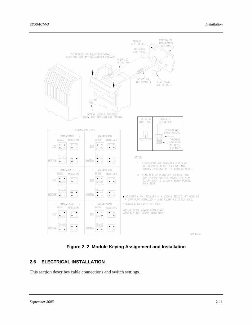
Modules are shipped individually packaged in protective, sealed, static shielding bags. Refer to Section 2.4.4 for module handling considerations. Each MODULRAC/SIXRAC slot and each module must be keyed to prevent accidental installation of a module into an incompatible slot. Keying is highly recommended. A unique keying pattern is assigned to each module type. See Figure 2-2 for ACM+ keying patterns.
A factory-assembled rack is keyed at the factory. A user-assembled rack must be keyed by the user according to the module types assigned each slot. Slot keying patterns must complement those of each module. MODULRACs/SIXRACs are supplied with stop plugs.
2.5.2.1 Module Rack Mechanical Keying
1. Get the MODULRAC Keying Kit supplied with the MODULRAC/SIXRAC.
2. Refer to Figure 2-2 and note the MODULRAC keying pattern. Also, locate the MODULRAC top and bottom rails.
3. Press the stop plugs into the holes identified by the solid dots.
SD39ACM-3 Installation
September 2005 2-9
Figure 2–1 ACM Transition Board Mounting
2.5.2.2 Module Installation
Use the following instructions to install the ACM+. Refer to Figure 2-2.
Installation SD39ACM-3
2-10 September 2005
1. Refer to user documentation for the correct module slot number and proper placement of the ACM transition board. For module-to-module redundancy, ACM+s are adjacently mounted in odd-even (1-2, 3-4, 7-8) slots.
2. Remove the ACM+ from its static shielding bag and ensure that the module is keyed. Also, check the rack slot to be sure it is keyed.
3. Insert the module in the assigned rack slot. Firmly seat the module in the back plane and transition board connectors. A properly seated module will have the rear of its bezel flush against the rack’s front rails. A keyed module that is not matched to a keyed slot will not engage the back plane or transition board connectors or seat flush against the rack’s front rails.
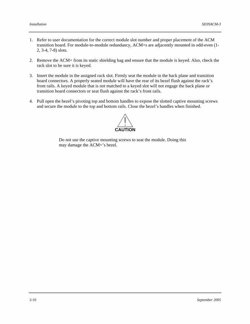
4. Pull open the bezel’s pivoting top and bottom handles to expose the slotted captive mounting screws and secure the module to the top and bottom rails. Close the bezel’s handles when finished.
CAUTION
Do not use the captive mounting screws to seat the module. Doing this may damage the ACM+’s bezel.
SD39ACM-3 Installation
September 2005 2-11
Figure 2–2 Module Keying Assignment and Installation
2.6 ELECTRICAL INSTALLATION
This section describes cable connections and switch settings.
Installation SD39ACM-3
2-12 September 2005
2.6.1 Cable Connections
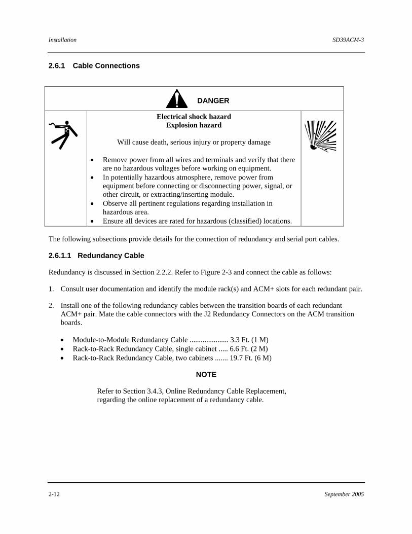
DANGER
Electrical shock hazard Explosion hazard
Will cause death, serious injury or property damage
• Remove power from all wires and terminals and verify that there
are no hazardous voltages before working on equipment. • In potentially hazardous atmosphere, remove power from
equipment before connecting or disconnecting power, signal, or other circuit, or extracting/inserting module.
• Observe all pertinent regulations regarding installation in hazardous area.
• Ensure all devices are rated for hazardous (classified) locations.
The following subsections provide details for the connection of redundancy and serial port cables.
2.6.1.1 Redundancy Cable
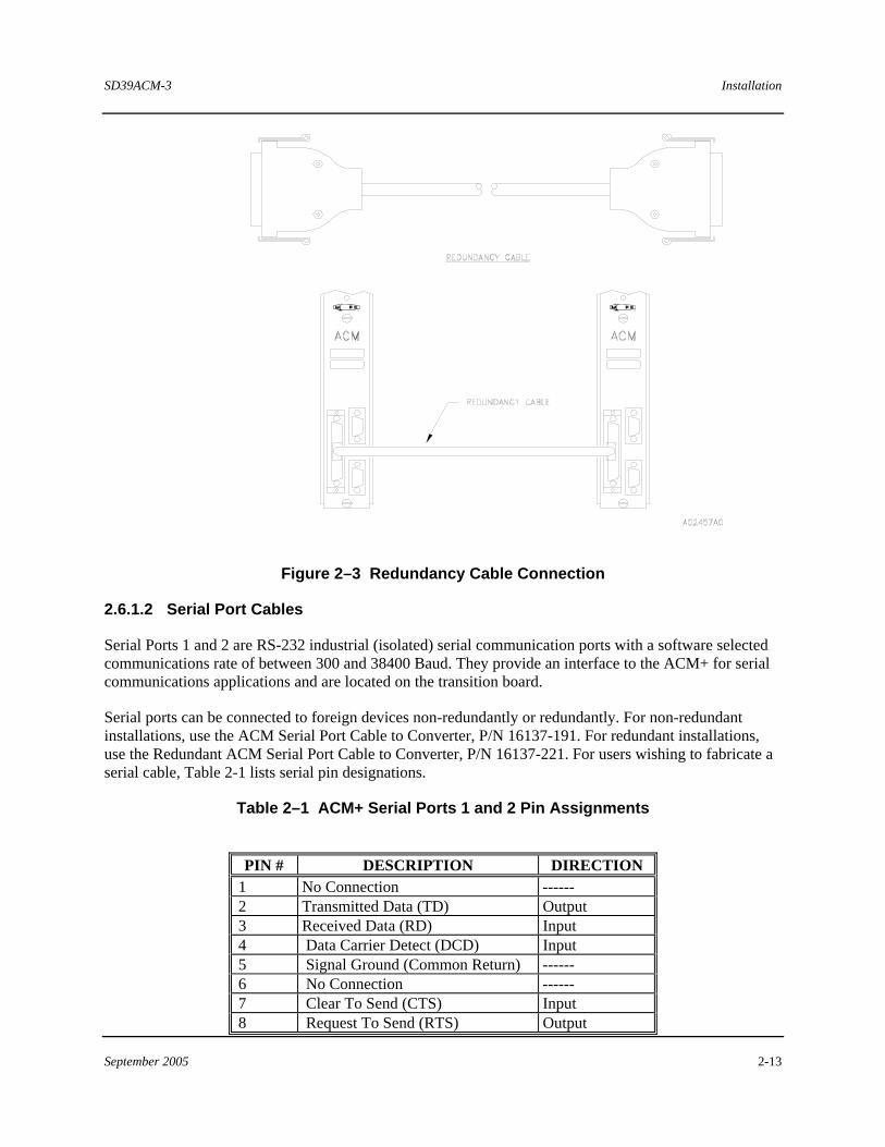
Redundancy is discussed in Section 2.2.2. Refer to Figure 2-3 and connect the cable as follows:
1. Consult user documentation and identify the module rack(s) and ACM+ slots for each redundant pair.
2. Install one of the following redundancy cables between the transition boards of each redundant ACM+ pair. Mate the cable connectors with the J2 Redundancy Connectors on the ACM transition boards.
• Module-to-Module Redundancy Cable ..................... 3.3 Ft. (1 M) • Rack-to-Rack Redundancy Cable, single cabinet ..... 6.6 Ft. (2 M) • Rack-to-Rack Redundancy Cable, two cabinets ....... 19.7 Ft. (6 M)
NOTE
Refer to Section 3.4.3, Online Redundancy Cable Replacement, regarding the online replacement of a redundancy cable.
SD39ACM-3 Installation
September 2005 2-13
Figure 2–3 Redundancy Cable Connection
2.6.1.2 Serial Port Cables
Serial Ports 1 and 2 are RS-232 industrial (isolated) serial communication ports with a software selected communications rate of between 300 and 38400 Baud. They provide an interface to the ACM+ for serial communications applications and are located on the transition board.
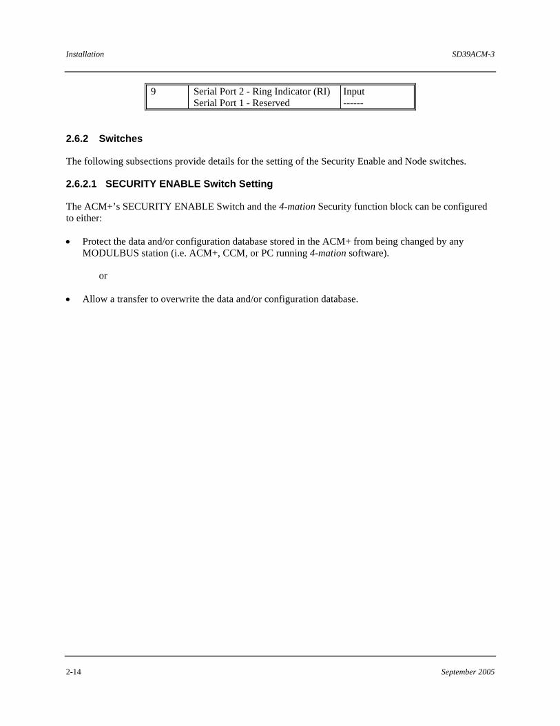
Serial ports can be connected to foreign devices non-redundantly or redundantly. For non-redundant installations, use the ACM Serial Port Cable to Converter, P/N 16137-191. For redundant installations, use the Redundant ACM Serial Port Cable to Converter, P/N 16137-221. For users wishing to fabricate a serial cable, Table 2-1 lists serial pin designations.
Table 2–1 ACM+ Serial Ports 1 and 2 Pin Assignments
PIN # DESCRIPTION DIRECTION
1 No Connection ------ 2 Transmitted Data (TD) Output 3 Received Data (RD) Input 4 Data Carrier Detect (DCD) Input 5 Signal Ground (Common Return) ------ 6 No Connection ------ 7 Clear To Send (CTS) Input 8 Request To Send (RTS) Output
Installation SD39ACM-3
2-14 September 2005
9 Serial Port 2 - Ring Indicator (RI) Serial Port 1 - Reserved
Input ------
2.6.2 Switches
The following subsections provide details for the setting of the Security Enable and Node switches.
2.6.2.1 SECURITY ENABLE Switch Setting
The ACM+’s SECURITY ENABLE Switch and the 4-mation Security function block can be configured to either:
• Protect the data and/or configuration database stored in the ACM+ from being changed by any MODULBUS station (i.e. ACM+, CCM, or PC running 4-mation software).
or
• Allow a transfer to overwrite the data and/or configuration database.
SD39ACM-3 Installation
September 2005 2-15
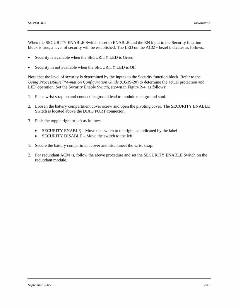
When the SECURITY ENABLE Switch is set to ENABLE and the EN input to the Security function block is true, a level of security will be established. The LED on the ACM+ bezel indicates as follows.
• Security is available when the SECURITY LED is Green
• Security in not available when the SECURITY LED is Off
Note that the level of security is determined by the inputs to the Security function block. Refer to the Using ProcessSuite™ 4-mation Configuration Guide (CG39-20) to determine the actual protection and LED operation. Set the Security Enable Switch, shown in Figure 2-4, as follows:
1. Place wrist strap on and connect its ground lead to module rack ground stud.
2. Loosen the battery compartment cover screw and open the pivoting cover. The SECURITY ENABLE Switch is located above the DIAG PORT connector.
3. Push the toggle right or left as follows.
• SECURITY ENABLE – Move the switch to the right, as indicated by the label • SECURITY DISABLE – Move the switch to the left
1. Secure the battery compartment cover and disconnect the wrist strap.
2. For redundant ACM+s, follow the above procedure and set the SECURITY ENABLE Switch on the redundant module.
Installation SD39ACM-3
2-16 September 2005
Figure 2–4 SECURITY ENABLE Switch
SD39ACM-3 Installation
September 2005 2-17
2.6.2.2 NODE Switch Setting
Every MODULBUS device, such as an ACM+, RIC/ICM, PC with MBI or MNI, RNI/NIM and MBX has an address associated with it. This address consists of the Node, Rack, and Slot identifiers. However, the ACM+ is different in that its Node identifier (also called number or address) is determined by one of the other M-BUS devices. The following subsections describe the procedures used to establish the operational Node number under which an ACM+ in a particular local area system will appear.
Proceed to the subsection that describes your specific local area system to determine the correct Node switch setting (0 or 1) on a particular ACM transition board.
Systems with an MBX
If the local area system (LAS) contains an MBX, the Node selector switch on the ACM transition board is ignored (leave it in 0 or 1 position). The ACM+ will appear with the same Node address as the MBX.
• The MBX Node address can be set to any number from 1 to 63. Each RNI/NIM, RIC/ICM, and PC with MBI should have its Node set to the same number as that of the MBX in that cluster. A PC with MNI can have the same Node number as the MBX or its own unique Node number, which is recommended.
• When using MBXs in Rack-to-Rack redundant systems, the first MBX is set to N and the second MBX is set to N+1, where N is an even number. (e.g. 2/3, 4/5, 6/7). Do not use 00 and 01.
• Do not change the Node address (SNA-System Node Address) when the MBX is powered (ACM+s will not pick up a change in Node address until the ACM+ is fully reinitialized (power down, remove battery).
Systems without an MBX
If the local area system (LAS) does not have an MBX, the ACM+�s Node address will be determined by the Node address of the first client that communicates to it and by the Node selector switch setting on its transition board. This client could be an RIC (or an ICM), PC with MBI, or an RNI (or NIM). Each of these devices has a Node number in the APACS.INI file (�Node=�). The ACM+�s ultimate Node address will depend on the Node address of one of these clients and on the setting of the Node selector switch on the ACM’s transition board (see Table 2-2).
• When an application is started on a client machine that then communicates with the ACM+, the ACM+ will use the Node address of the client and its selector switch to determine its operational Node address. Running 4-mation on-line and just opening the module tree is enough to start this process.
• If the application is run from a PC over Ethernet, the Node address of the RNI/NIM is actually used; not that of the PC. However, when setting up the architecture, the PC and RNI/NIM would typically have the same node number; if only for system documentation reasons.
Installation SD39ACM-3
2-18 September 2005
IMPORTANT
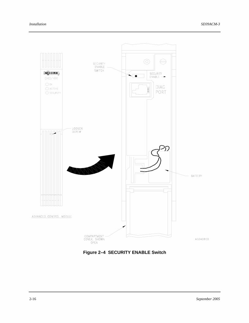
The Node switch setting on the ACM transition board determines the ultimate Node address used by the ACM+ (with no MBX present). See Table 2-2 to determine an ACM+’s Node address.
Table 2–2 Determining ACM+’s Node Address
CLIENT’S NODE ADDRESS
EFFECT OF ACM+ NODE SWITCH
(WHEN NO MBX IS PRESENT)
EXAMPLES
EVEN (including 0) Add the Switch setting to determine
the ACM+�s final Node address 1. Client=4, ACM+ Node Switch=0
yields ACM+ Node=4 2. Client=4, ACM+ Node Switch=1
yields ACM+ Node=5 ODD Switch=0; ACM+ Node is one less
than client Switch=1; ACM+ Node equals client
1. Client=7, ACM+ Node Switch=0 yields ACM+ Node=6
Client=7, ACM+ Node 2. Switch=1 yields ACM+ Node=7
• An ACM transition board must always be installed for each ACM+, even when redundancy and serial ports are not being used.
• An older ACM transition board without the Node selector switch will operate as if the switch is set to 0.
• For Module-to-Module redundant ACM+s, the switches should be equal (both 0 or both 1). The criteria in Table 2-2 will still apply in determining the operational Node address of the ACM+.
IMPORTANT
If you need to change the Node number of an ACM+, the ACM+ must be fully reinitialized to take on the new Node number. To fully reinitialize the ACM+, pull the ACM+, remove the battery, wait about 1 minute, reinstall the battery, then reinsert the ACM+.
It is not recommended to change the Node address of an MBX while ACM+s are on-line. The ACM+ will keep the original Node number and will log an error, System Service Code 28, Error Code 03. You must fully reinitialize the ACM+ in order to have it appear with the new Node address.
SD39ACM-3 Installation
September 2005 2-19
2.6.3 RAM Battery
The purpose of the RAM battery is to retain memory contents and real-time clock operation during power interruptions. The battery MUST be connected just prior to applying power to the ACM+. See Section 6 for battery life data.
IMPORTANT
When powered up, a disconnected or failed battery or a battery with a voltage below specifications will cause the ACM+ to reset.
Note the following:
• It is recommended that the battery be disconnected to preserve battery life when the module is placed in storage or stock.
• The battery is disconnected when a module is shipped from the factory.
To check the status of the battery, and connect the battery if it is disconnected, perform the following steps:
1. Place wrist strap on wrist and connect ground lead to module rack’s ground stud. ESD protection is required when the battery compartment is opened.
2. Loosen the battery compartment cover screw and open the pivoting cover.
3. Refer to Figure 2-4 and note the location of the battery and its plug.
4. If the module’s battery is not connected, orient the keyed plug and push it onto the circuit board connector pins. If the module’s battery is connected, proceed to step 5.
5. Proceed to Section 2.6.2.1 to set the SECURITY ENABLE Switch and close the battery compartment door.

SD39ACM-3 Maintenance
September 2005 3-1
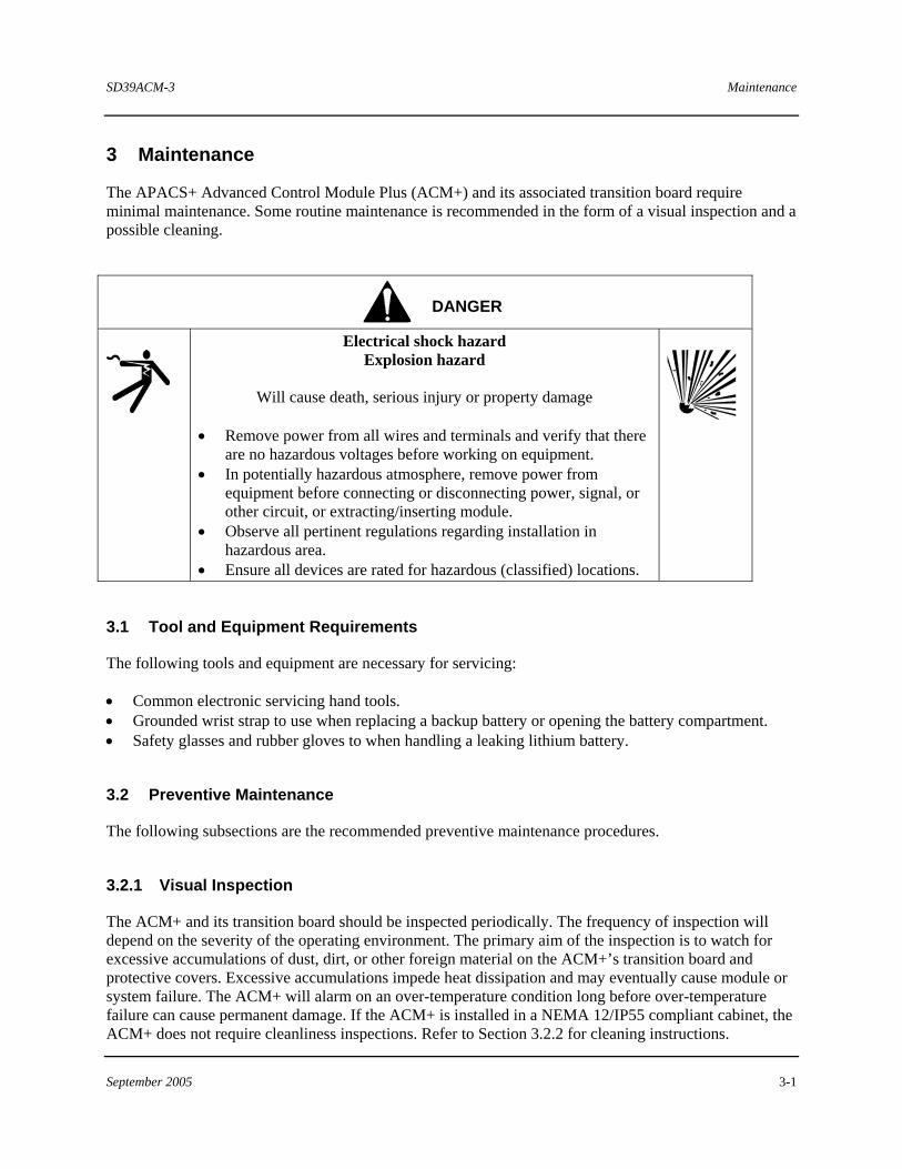
3 Maintenance
The APACS+ Advanced Control Module Plus (ACM+) and its associated transition board require minimal maintenance. Some routine maintenance is recommended in the form of a visual inspection and a possible cleaning.
DANGER
Electrical shock hazard Explosion hazard
Will cause death, serious injury or property damage
• Remove power from all wires and terminals and verify that there
are no hazardous voltages before working on equipment. • In potentially hazardous atmosphere, remove power from
equipment before connecting or disconnecting power, signal, or other circuit, or extracting/inserting module.
• Observe all pertinent regulations regarding installation in hazardous area.
• Ensure all devices are rated for hazardous (classified) locations.
3.1 Tool and Equipment Requirements
The following tools and equipment are necessary for servicing:
• Common electronic servicing hand tools. • Grounded wrist strap to use when replacing a backup battery or opening the battery compartment. • Safety glasses and rubber gloves to when handling a leaking lithium battery.
3.2 Preventive Maintenance
The following subsections are the recommended preventive maintenance procedures.
3.2.1 Visual Inspection
The ACM+ and its transition board should be inspected periodically. The frequency of inspection will depend on the severity of the operating environment. The primary aim of the inspection is to watch for excessive accumulations of dust, dirt, or other foreign material on the ACM+’s transition board and protective covers. Excessive accumulations impede heat dissipation and may eventually cause module or system failure. The ACM+ will alarm on an over-temperature condition long before over-temperature failure can cause permanent damage. If the ACM+ is installed in a NEMA 12/IP55 compliant cabinet, the ACM+ does not require cleanliness inspections. Refer to Section 3.2.2 for cleaning instructions.
Maintenance SD39ACM-3
3-2 September 2005
The ACM+ status is indicated by LEDs located on its bezel. Refer to Section 3.3.2 for LED indications.
3.2.2 Cleaning
Cleaning a module involves brushing or vacuuming the protective covers to restore cooling efficiency that may have been degraded by accumulated dust.
Cleaning a transition board involves careful brushing and vacuuming to remove accumulated dust and dirt harboring chemical particulate that may accelerate terminal, switch, or connector contact corrosion.
3.3 Troubleshooting
Fault analysis focuses on identifying a failure annunciated by the operator interface, or by status LEDs located on the ACM+’s bezel. If the operator interface alarm blocks have been configured, module errors will be reported. The operator can access error code descriptions and recommended corrective actions.
Failure annunciation and fault analysis is also available within 4-mation software (refer to Using the ProcessSuite 4-mation Configuration Software, CG39-20, located in binder UM39-11). The on-line display of the Module Tree in 4-mation graphically represents both the hardware modules that comprise a system and the function that hardware performs. There is an entry in the Tree for each module including its node, rack, and slot address.
In the Module Tree, ACM+ symbols are displayed to the left of the address. When 4-mation is running in the on-line mode, these symbols are displayed in one of three colors, depending upon a module’s state of operation:
• Red – Indicates a module which is not initialized • Yellow – Indicates a module which is initialized but not configured • Green – Indicates a configured module
The ACM+ address text (e.g. [R01,S02] ) is displayed in one of four colors, based on error status:
• White – Indicates that error information could not be obtained from the module • Red – Indicates the module has errors • Green – Indicates the module has no errors • Yellow – Indicates the resource module has no errors but its I/O module(s) do
Once a fault is identified, correct the fault by replacing the failed ACM+ with a known good module and return the failed ACM+ to one of the addresses in the warranty statement for repair.
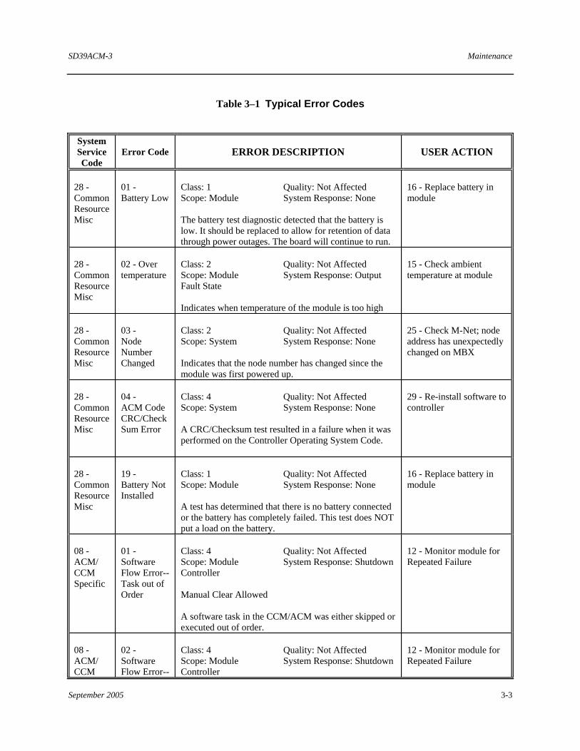
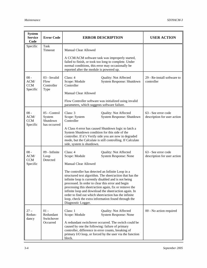
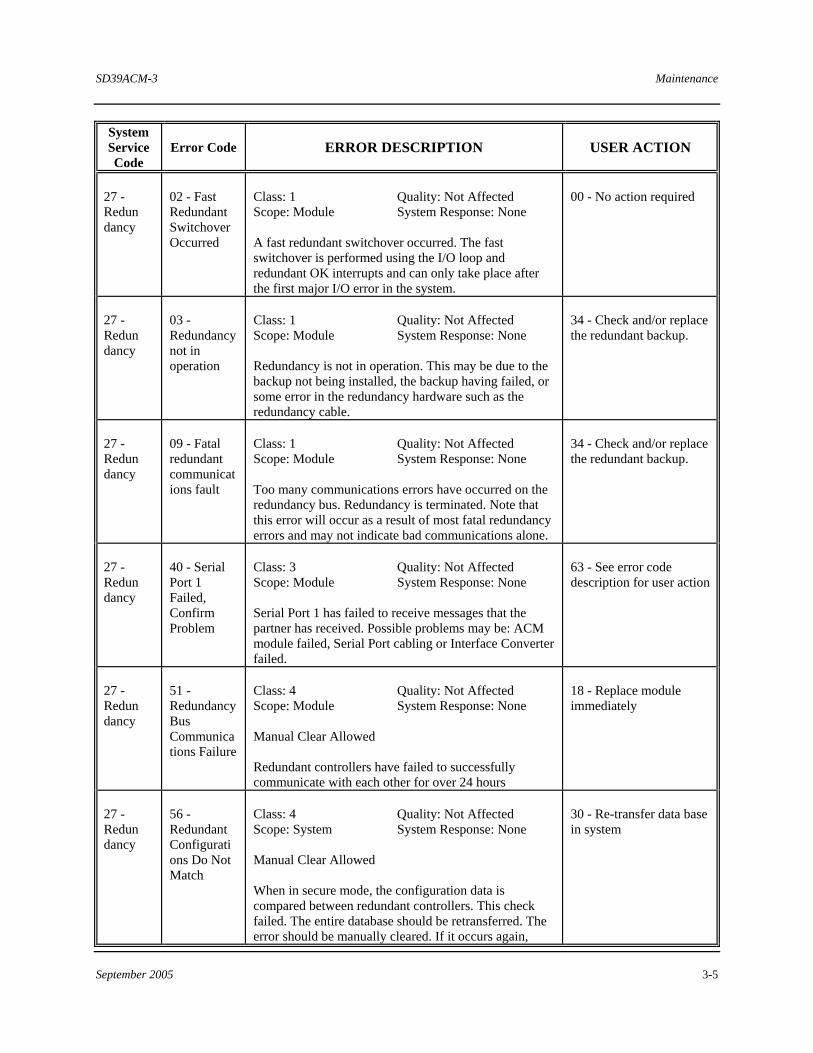
3.3.1 Typical ACM+ Error Codes
Table 3-1 lists typical error codes associated with ACM+s. For a detailed description of all module error codes, refer to ProcessSuite Module Diagnostic Error Codes (CG39-19) located in binder UM39-14.
SD39ACM-3 Maintenance
September 2005 3-3
Table 3–1 Typical Error Codes
System Service Code
Error Code ERROR DESCRIPTION USER ACTION
28 - Common Resource Misc
01 - Battery Low
Class: 1 Quality: Not Affected Scope: Module System Response: None The battery test diagnostic detected that the battery is low. It should be replaced to allow for retention of data through power outages. The board will continue to run.
16 - Replace battery in module
28 - Common Resource Misc
02 - Over temperature
Class: 2 Quality: Not Affected Scope: Module System Response: Output Fault State Indicates when temperature of the module is too high
15 - Check ambient temperature at module
28 - Common Resource Misc
03 - Node Number Changed
Class: 2 Quality: Not Affected Scope: System System Response: None Indicates that the node number has changed since the module was first powered up.
25 - Check M-Net; node address has unexpectedly changed on MBX
28 - Common Resource Misc
04 - ACM Code CRC/Check Sum Error
Class: 4 Quality: Not Affected Scope: System System Response: None A CRC/Checksum test resulted in a failure when it was performed on the Controller Operating System Code.
29 - Re-install software to controller
28 - Common Resource Misc
19 - Battery Not Installed
Class: 1 Quality: Not Affected Scope: Module System Response: None A test has determined that there is no battery connected or the battery has completely failed. This test does NOT put a load on the battery.
16 - Replace battery in module
08 - ACM/ CCM Specific
01 - Software Flow Error-- Task out of Order
Class: 4 Quality: Not Affected Scope: Module System Response: Shutdown Controller Manual Clear Allowed A software task in the CCM/ACM was either skipped or executed out of order.
12 - Monitor module for Repeated Failure
08 - ACM/ CCM
02 - Software Flow Error--
Class: 4 Quality: Not Affected Scope: Module System Response: Shutdown Controller
12 - Monitor module for Repeated Failure
Maintenance SD39ACM-3
3-4 September 2005
System Service Code
Error Code ERROR DESCRIPTION USER ACTION
Specific
Task Timeout
Manual Clear Allowed A CCM/ACM software task was improperly started, failed to finish, or took too long to complete. Under normal conditions, this error may occasionally be reported after the module is powered up.
08 - ACM/ CCM Specific
03 - Invalid Flow Controller Type
Class: 4 Quality: Not Affected Scope: Module System Response: Shutdown Controller Manual Clear Allowed Flow Controller software was initialized using invalid parameters, which suggests software failure.
29 - Re-install software to controller
08 - ACM/ CCM Specific
05 - Control System Shutdown has occurred
Class: 3 Quality: Not Affected Scope: System System Response: Shutdown Controller A Class 4 error has caused Shutdown logic to latch a System Shutdown condition for this side of the controller. If it’s Verify side you are now in degraded mode, but the Calculate is still controlling. If Calculate side, system is shutdown.
63 - See error code description for user action
08 - ACM/ CCM Specific
09 - Infinite Loop Detected
Class: 4 Quality: Not Affected Scope: Module System Response: None Manual Clear Allowed The controller has detected an Infinite Loop in a structured text algorithm. The sheet/action that has the infinite loop is currently disabled and is not being processed. In order to clear this error and begin processing this sheet/action again, fix or remove the infinite loop and download the sheet/action again. In order to find out which sheet/action has the infinite loop, check the extra information found through the Diagnostic Logger.
63 - See error code description for user action
27 – Redun-dancy
01 - Redundant Switchover Occurred
Class: 1 Quality: Not Affected Scope: Module System Response: None A redundant switchover occurred. The switch could be caused by one the following: failure of primary controller, difference in error counts, breaking of primary I/O loop, or forced by the user via the function block.
00 - No action required
SD39ACM-3 Maintenance
September 2005 3-5
System Service Code
Error Code ERROR DESCRIPTION USER ACTION
27 - Redun dancy
02 - Fast Redundant Switchover Occurred
Class: 1 Quality: Not Affected Scope: Module System Response: None A fast redundant switchover occurred. The fast switchover is performed using the I/O loop and redundant OK interrupts and can only take place after the first major I/O error in the system.
00 - No action required
27 - Redun dancy
03 - Redundancy not in operation
Class: 1 Quality: Not Affected Scope: Module System Response: None Redundancy is not in operation. This may be due to the backup not being installed, the backup having failed, or some error in the redundancy hardware such as the redundancy cable.
34 - Check and/or replace the redundant backup.
27 - Redun dancy
09 - Fatal redundant communications fault
Class: 1 Quality: Not Affected Scope: Module System Response: None Too many communications errors have occurred on the redundancy bus. Redundancy is terminated. Note that this error will occur as a result of most fatal redundancy errors and may not indicate bad communications alone.
34 - Check and/or replace the redundant backup.
27 - Redun dancy
40 - Serial Port 1 Failed, Confirm Problem
Class: 3 Quality: Not Affected Scope: Module System Response: None Serial Port 1 has failed to receive messages that the partner has received. Possible problems may be: ACM module failed, Serial Port cabling or Interface Converter failed.
63 - See error code description for user action
27 - Redun dancy
51 - Redundancy Bus Communications Failure
Class: 4 Quality: Not Affected Scope: Module System Response: None Manual Clear Allowed Redundant controllers have failed to successfully communicate with each other for over 24 hours
18 - Replace module immediately
27 - Redun dancy
56 - Redundant Configurations Do Not Match
Class: 4 Quality: Not Affected Scope: System System Response: None Manual Clear Allowed When in secure mode, the configuration data is compared between redundant controllers. This check failed. The entire database should be retransferred. The error should be manually cleared. If it occurs again,
30 - Re-transfer data base in system
Maintenance SD39ACM-3
3-6 September 2005
System Service Code
Error Code ERROR DESCRIPTION USER ACTION
replace module.
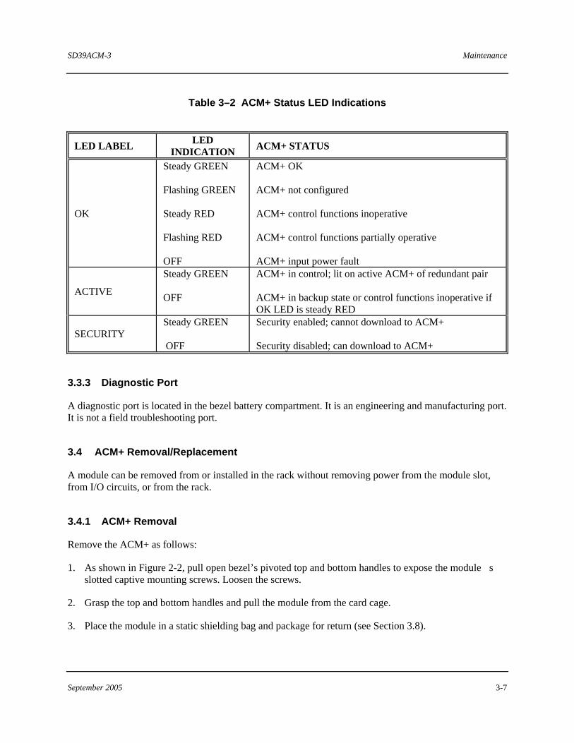
3.3.2 Bezel LEDs
Three LEDs on the ACM+ bezel show module status as indicated in Table 3-2.
SD39ACM-3 Maintenance
September 2005 3-7
Table 3–2 ACM+ Status LED Indications
LED LABEL LED INDICATION ACM+ STATUS
OK
Steady GREEN Flashing GREEN Steady RED Flashing RED OFF
ACM+ OK ACM+ not configured ACM+ control functions inoperative ACM+ control functions partially operative ACM+ input power fault
ACTIVE
Steady GREEN OFF
ACM+ in control; lit on active ACM+ of redundant pair ACM+ in backup state or control functions inoperative if OK LED is steady RED
SECURITY Steady GREEN OFF
Security enabled; cannot download to ACM+ Security disabled; can download to ACM+
3.3.3 Diagnostic Port
A diagnostic port is located in the bezel battery compartment. It is an engineering and manufacturing port. It is not a field troubleshooting port.
3.4 ACM+ Removal/Replacement
A module can be removed from or installed in the rack without removing power from the module slot, from I/O circuits, or from the rack.
3.4.1 ACM+ Removal
Remove the ACM+ as follows:
1. As shown in Figure 2-2, pull open bezel’s pivoted top and bottom handles to expose the module�s slotted captive mounting screws. Loosen the screws.
2. Grasp the top and bottom handles and pull the module from the card cage.
3. Place the module in a static shielding bag and package for return (see Section 3.8).
Maintenance SD39ACM-3
3-8 September 2005
3.4.2 ACM+ Replacement
Replace the ACM+ as follows:
1. Remove the replacement ACM+ from its protective bag. Its protective covers permit the ACM+ to be handled without a grounded wrist strap.
2. Insert the module in its MODULRAC slot. Firmly seat the module in the back plane and termination board connectors. A properly seated module will have the rear of its bezel flush against the MODULRAC housing rails.
NOTE
A keyed module that is not matched to a slot will not engage the back plane or termination board connectors or seat flush against the MODULRAC housing’s front rails.
3. As shown in Figure 2-2, pull open bezel�s pivoted top and bottom handles to expose the module�s slotted captive mounting screws and secure the module to the top and bottom rails. Close the bezel’� handles when finished.
CAUTION
Do not use the captive mounting screws to seat the module. Doing this may damage the bezel..
4. Ensure the battery is enabled (see Section 2.6.3) and set the Security Enable switch as described in Section 2.6.2.1.
SD39ACM-3 Maintenance
September 2005 3-9
3.4.3 Online Redundancy Cable Replacement
1. Remove the backup (verify) controller
2. Remove the old cable from the primary (calculate) termination strip.
3. Remove the old cable from the backup (verify) termination strip.
4. Insert and screw down the new cable to the backup (verify) termination strip.
5. Insert and screw down the new cable to the primary (calculate) termination strip.
6. Insert the backup (verify) controller.
3.5 Transition Board Removal/Replacement
3.5.1 Removal
Refer to Figure 2-1 and the following removal procedure:
1. As necessary, take appropriate steps to shutdown the processes monitored or controlled by the field devices controlled by the ACM+.
2. Remove the associated ACM+ from its slot in the module rack; see Section 3.4.1. Place the module in a static shielding bag for protection.
3. Remove redundancy and serial port cables from the transition board.
IMPORTANT
All cables should be labeled for correct reconnection.
4. Loosen the transition board�s captive mounting screws. Gently lift the bottom of the board in an arc until the board is free of its alignment pin located immediately above the Siemens logo. Pull the top of the transition board from the grooved back plane spacer and lift it from the module rack.
3.5.2 Replacement
Refer to Figure 2-1 and the following replacement procedure:
1. Refer to Section 2.5.1 and install the replacement transition board.
2. Reconnect redundancy and serial port cables.
3. Install the ACM+ as described in Section 3.4.2.
Maintenance SD39ACM-3
3-10 September 2005
IMPORTANT
Be sure that the battery is connected. Refer to Section 3.6.1 for the connection procedure.
3.6 Component Replacement
3.6.1 RAM Battery Replacement
A 3.6V lithium battery is housed in the module�s bezel battery compartment. When power is removed from the ACM+, the battery maintains ACM+ memory (RAM) to retain the configuration and executable code.
Batter condition is monitored by software. System Service Code (SSC) 28 and Error Code (EC) 01 will indicate a weak battery. SSC 28, EC 19 will indicate a disconnected battery. The error code and message will be displayed on a system computer running 4-mation Release 2 or higher software.
If the battery is weak and a configuration is stored in the ACM+, replace the battery with power applied to the ACM+. If the configuration is lost, it can be quickly downloaded using 4-mation software.
Replace a battery as follows:
1. To protect the ACM+ from electrostatic discharge, snap on a wrist strap and connect its ground lead to the ground stud on the module rack panel.
2. Loosen the bezel compartment screw and open the door. See Figure 2-4.
3. Unplug the battery; note how the connector is keyed.
4. Pull the battery from the compartment; a cloth hook and loop fastener secures the battery.
5. The replacement battery is supplied with a new hook and loop fastener. Separate the fastener halves.
6. If the compartment-mounted portion of the fastener is damaged, remove it and install the separated fastener half.
7. Mount the new RAM battery in the compartment.
8. Orient the keyed battery connector and plug it into the circuit board mounted connector.
9. Close and secure the battery compartment door. Remove the wrist strap.
SD39ACM-3 Maintenance
September 2005 3-11
WARNING
Be advised of the following with regard to handling lithium batteries:
• Properly dispose of a removed battery. • Do not burn a battery. • Do not short circuit battery terminals. • Do not attempt to charge the battery. • If battery electrolyte leaks, wear safety glasses and rubber gloves to avoid exposure.
3.7 Spare And Replacement Parts
One spare ACM+ and battery should be stocked for every 1 to 10 in service. Spare and replacement parts can be ordered from one of the addresses in the Warranty statement or through a local Siemens representative.
Assembly part numbers are provided in Section 1 and printed on most modules and associated hardware. The battery part number is listed as follows:
DESCRIPTION PART NUMBER
Battery, 3.6 V 14743-2
When ordering, provide the model number, part number, serial number, and software compatibility identification code from the module to be replaced or spared. A purchase order number should also be included.
WARNING
Be advised of the following with regard to storing a Lithium Battery:
• Store the battery in original shipping container • Do not store battery loosely in a metal bin or short circuit battery terminals • Store a battery in a cool well-ventilated area • Maximum storage temperature should not exceed 85 °C (185 °F)
Maintenance SD39ACM-3
3-12 September 2005
IMPORTANT
When placing an ACM+ in spare parts stock, unplug the battery connector. This will extend battery life. Refer to Section 3.6.1 for the procedure. Also, cooler storage temperatures extends battery life.
3.8 Return of Equipment within North America
US Customers:
• Call the Repair Order PAS Inside Sales/Order Management Group at (215) 646-7400, ext 4RMA (4762) weekdays between 8:00 a.m. and 4:45 p.m. eastern time to obtain an RMA number. Mark the RMA number prominently on the outside of the shipment.
• When calling for an RMA number, provide the reason for the return. If returning equipment for repair, a detailed description of failure symptoms and system behavior will be requested. Supply a purchase order number for repairs. Follow the TSC specialist's recommendation for battery connection, if applicable.
• If applicable, you must supply a Material Safety Data Sheet (MSDS) with each item being returned if it was stored or used in a location where hazardous materials were present.
• Package items to be returned in their original shipping containers. Otherwise, package it for safe shipment or contact the factory for shipping recommendations. A module must be placed inside a static shielding bag to protect it from electrostatic discharge.
Canadian customers:
Contact Siemens Canada.
3.8.1 Return of Equipment outside North America
Contact your Siemens Representative.
3.9 Software Compatibility
The Advanced Controller Module contains two nameplate labels: a large label, shown below, located on the tracking plate (left side of ACM+ in Figure 1-1), and a small label inside the bezel battery compartment. Both labels contain the module’s Software ROM Version as well as the Model Designation, Part Number, and Serial Number.
MODEL 39ACM24BDN AMPS x.xxx A P/N 16139-205 ROM VERSION 3.xx VOLTS 24 VDC S/N xxxxxxxx
SD39ACM-3 Maintenance
September 2005 3-13
The following guidelines should be observed to ensure software compatibility between ACM+s:
• Module-to-Module Redundancy: Both ACM+s should have the same software level installed • Rack-to-Rack Redundancy: Both ACM+s should have the same software level installed • Spare ACM+s: The software level of the spare module and module being replaced should agree.
Questions concerning the compatibility of different releases of software for the same type module (ACM+) should be directed to the APACS+ Controller Product Specialist at Siemens.
3.10 Maintenance Records
An accurate record keeping system for tracking maintenance operations should be established and kept up to date. Data extracted from the record may serve as a base for ordering maintenance supplies, including spare parts. The record may also be useful as a troubleshooting tool. In addition, maintenance records may be required to provide documentary information in association with a service contract. It is suggested that the following information be recorded:
• Date of service incident • Name or initials of service person • Brief description of incident symptoms and repairs performed • Replacement part or assembly number • Software compatibility code of original part • Software code of replacement part • Serial number of original part • Serial number of replacement part • Issue number of original circuit module • Issue number of replacement circuit module • Date of completion

SD39ACM-3 Circuit Description
September 2005 4-1
4 Circuit Description
This section provides a brief circuit description of the Advanced Control Module Plus (ACM+). See Figure 4-1.
4.1 ACM+ Functional Elements
Functionally, the ACM+ consists of the following elements:
• 68040 CPU with internal floating point coprocessor • 68302 peripheral controller • 68824 token bus controller • IOBUS modem with redundant drivers • MODULBUS modem with redundant drivers • 4MB or 8MB battery-backed RAM • 512K flash boot PROM • Dual DMA RS-232 serial communication ports • Small Computer Systems Interface (SCSI) redundancy port • Watchdog timer • 1 MB flash EEPROM for operating system software
The 68040 CPU provides the computing power of a 32-bit architecture and instruction and data caches. Internal operations in the 68040 CPU run at 66 MHz while its bus operations run at 33 MHz. The floating point coprocessor performs floating point computations which allows the CPU to more quickly execute its program tasks.
4.2 Watchdog/Reset
During an ACM+ power-up, the Watchdog generates a system reset while the IC supply voltage from the on-board power supply is rising to its operating value. During ACM+ operation, if at any time the IC supply voltage drops below 4.5V, the Watchdog will generate a reset to shut off RAM decode MOSFETS to protect the RAM from invalid access during a power supply failure.
Circuit Description SD39ACM-3
4-2 September 2005
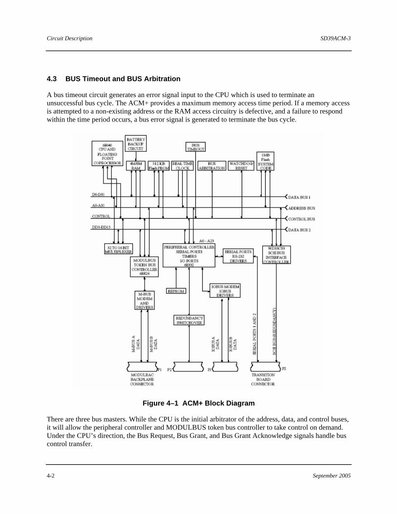
4.3 BUS Timeout and BUS Arbitration
A bus timeout circuit generates an error signal input to the CPU which is used to terminate an unsuccessful bus cycle. The ACM+ provides a maximum memory access time period. If a memory access is attempted to a non-existing address or the RAM access circuitry is defective, and a failure to respond within the time period occurs, a bus error signal is generated to terminate the bus cycle.
Figure 4–1 ACM+ Block Diagram
There are three bus masters. While the CPU is the initial arbitrator of the address, data, and control buses, it will allow the peripheral controller and MODULBUS token bus controller to take control on demand. Under the CPU’s direction, the Bus Request, Bus Grant, and Bus Grant Acknowledge signals handle bus control transfer.
SD39ACM-3 Circuit Description
September 2005 4-3
4.4 RAM and ROM
An ACM+ has 4 or 8 MB of battery-backed states static RAM, 512 KB of flash PROM, and 1 MB of flash for operating system code. RAM is accessible by all three bus masters. Memory chip selection is accomplished by a RAM bus decode circuit.
The ACM+’s application-specific configuration and operating system software is downloaded from a workstation, or a personal computer connected to the APACS+ system. The application-specific configuration is stored in ACM+ memory (RAM); whereas, the operating system is stored in the FLASH EEPROM memory. A 3.6V lithium battery allows RAM contents to be retained when power is removed from the ACM+. Software detects a weak or disconnected battery, and an error code displays on a personal computer screen.
4.5 Serial Ports
The serial ports available on the ACM Transition Board are wired for direct connection to the COM port of a personal computer. Connection to a printer requires a null modem. The peripheral controller and a RS-232 line driver/receiver control each port.
4.6 MODULBUS
The MODULBUS elements consist of a Token Bus Controller (TBC), M-BUS modem, and M-BUS line drivers/receivers.
The TBC is an intelligent peripheral device to the peripheral controller. The peripheral controller supervises the TBC, which implements the media access control portion of the IEEE 802.4 token passing bus standard. The TBC communicates serially with the MODULBUS modem, which is interfaced to MODULBUS through dual line drivers/receivers.
The TBC performs the following:
• Manages the ordered access to the token bus medium (MODULBUS) • Provides a means for the admission and deletion of modules • Handles fault recovery
The MODULBUS Modem performs the following:
• Converts received MODULBUS data into a form compatible for data processing • Converts serial data from the TBC into a form compatible for transmission over the MODULBUS
4.7 IOBUS
The IOBUS elements consist of an IOBUS modem and dual IOBUS line drivers/receivers. The 68302 Controller supervises IOBUS communications through handshaking operations with the IOBUS modem. The modem and dual line drivers/receivers perform the same tasks as described for the M-BUS modem and line drivers/receivers.
Circuit Description SD39ACM-3
4-4 September 2005
4.8 Small Computer System Interface (SCSI) and Redundancy
The SCSI redundancy port elements consist of a redundancy switchover circuit and an SCSI bus interface controller. The peripheral controller supervises redundant switchover and the SCSI bus.
Redundant ACM+s (rack-to-rack) communicate with each other over the high-speed SCSI bus. The SCSI bus controller interfaces the peripheral controller to the SCSI bus. SCSI bus communications are the exchange of I/O and diagnostic data between the primary and backup ACM+s.
A primary-to-backup ACM+ switchover occurs in one of the following three ways:
• An operator can initiate a switchover if the Redundancy Control Function Block is configured (see the APACS+ 4-mation Configuration Guide).
• The standby ACM+ receives and stores all IOBUS data while in the standby mode. An exchange of data is made over the SCSI bus so both ACM+s can confirm and compare the others received data. If the data received by the backup from the active ACM+ contains any data-check error flags posted by the active ACM+, a switchover is initiated by the standby.
• The active ACM+ sends an OK flag to the standby ACM+ as part of the exchange of diagnostic information. The OK flag indicates the ACM+ is functioning normally as a controller. If the active ACM+’s onboard diagnostics detects a fault affecting ACM+ control, a NOT-OK flag is posted and the backup initiates a switchover.
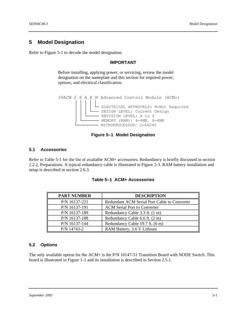
SD39ACM-3 Model Designation
September 2005 5-1
5 Model Designation
Refer to Figure 5-1 to decode the model designation.
IMPORTANT
Before installing, applying power, or servicing, review the model designation on the nameplate and this section for required power, options, and electrical classification.
39ACM 2 8 A E N Advanced Control Module (ACM+)
│ │ │ │ │ │ │ │ │ └─ ELECTRICAL APPROVALS: N=Not Required │ │ │ └─── DESIGN LEVEL: Current Design │ │ └───── REVISION LEVEL: A to Z │ └─────── MEMORY (RAM): 4=4MB, 8=8MB └───────── MICROPROCESSOR: 2=68040
Figure 5–1 Model Designation
5.1 Accessories
Refer to Table 5-1 for the list of available ACM+ accessories. Redundancy is briefly discussed in section 2.2.2, Preparations. A typical redundancy cable is illustrated in Figure 2-3. RAM battery installation and setup is described in section 2.6.3.
Table 5–1 ACM+ Accessories
PART NUMBER DESCRIPTION
P/N 16137-221 Redundant ACM Serial Port Cable to Converter P/N 16137-191 ACM Serial Port to Converter P/N 16137-189 Redundancy Cable 3.3 ft. (1 m) P/N 16137-188 Redundancy Cable 6.6 ft. (2 m) P/N 16137-144 Redundancy Cable 19.7 ft. (6 m)
P/N 14743-2 RAM Battery, 3.6 V Lithium
5.2 Options
The only available option for the ACM+ is the P/N 16147-51 Transition Board with NODE Switch. This board is illustrated in Figure 1-1 and its installation is described in Section 2.5.1.

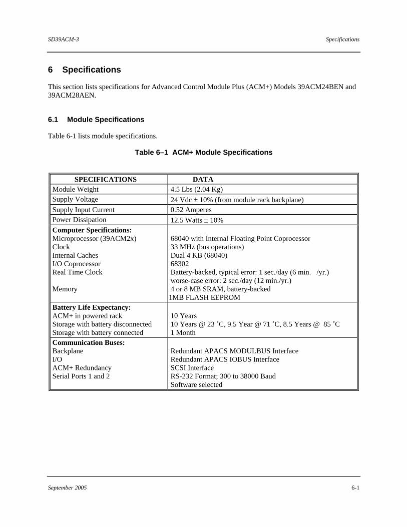
SD39ACM-3 Specifications
September 2005 6-1
6 Specifications
This section lists specifications for Advanced Control Module Plus (ACM+) Models 39ACM24BEN and 39ACM28AEN.
6.1 Module Specifications
Table 6-1 lists module specifications.
Table 6–1 ACM+ Module Specifications
SPECIFICATIONS DATA Module Weight 4.5 Lbs (2.04 Kg) Supply Voltage 24 Vdc ± 10% (from module rack backplane) Supply Input Current 0.52 Amperes Power Dissipation 12.5 Watts ± 10% Computer Specifications: Microprocessor (39ACM2x) Clock Internal Caches I/O Coprocessor Real Time Clock Memory
68040 with Internal Floating Point Coprocessor 33 MHz (bus operations) Dual 4 KB (68040) 68302 Battery-backed, typical error: 1 sec./day (6 min. /yr.) worse-case error: 2 sec./day (12 min./yr.) 4 or 8 MB SRAM, battery-backed 1MB FLASH EEPROM
Battery Life Expectancy: ACM+ in powered rack Storage with battery disconnected Storage with battery connected
10 Years 10 Years @ 23 ˚C, 9.5 Year @ 71 ˚C, 8.5 Years @ 85 ˚C 1 Month
Communication Buses: Backplane I/O ACM+ Redundancy Serial Ports 1 and 2
Redundant APACS MODULBUS Interface Redundant APACS IOBUS Interface SCSI Interface RS-232 Format; 300 to 38000 Baud Software selected
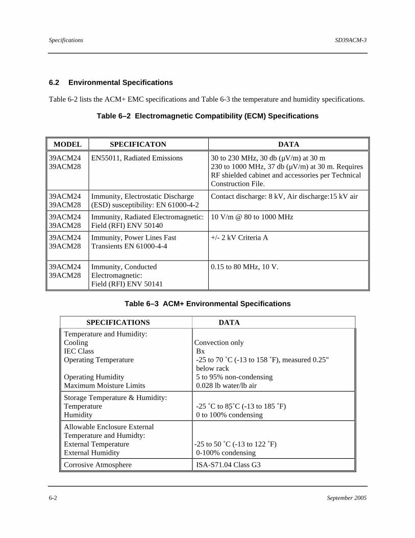
Specifications SD39ACM-3
6-2 September 2005
6.2 Environmental Specifications
Table 6-2 lists the ACM+ EMC specifications and Table 6-3 the temperature and humidity specifications.
Table 6–2 Electromagnetic Compatibility (ECM) Specifications
MODEL SPECIFICATON DATA
39ACM24 39ACM28
EN55011, Radiated Emissions 30 to 230 MHz, 30 db (µV/m) at 30 m 230 to 1000 MHz, 37 db (µV/m) at 30 m. Requires RF shielded cabinet and accessories per Technical Construction File.
39ACM24 39ACM28
Immunity, Electrostatic Discharge (ESD) susceptibility: EN 61000-4-2
Contact discharge: 8 kV, Air discharge:15 kV air
39ACM24 39ACM28
Immunity, Radiated Electromagnetic: Field (RFI) ENV 50140
10 V/m @ 80 to 1000 MHz
39ACM24 39ACM28
Immunity, Power Lines Fast Transients EN 61000-4-4
+/- 2 kV Criteria A
39ACM24 39ACM28
Immunity, Conducted Electromagnetic: Field (RFI) ENV 50141
0.15 to 80 MHz, 10 V.
Table 6–3 ACM+ Environmental Specifications
SPECIFICATIONS DATA Temperature and Humidity: Cooling IEC Class Operating Temperature Operating Humidity Maximum Moisture Limits
Convection only Bx -25 to 70 ˚C (-13 to 158 ˚F), measured 0.25" below rack 5 to 95% non-condensing 0.028 lb water/lb air
Storage Temperature & Humidity: Temperature Humidity
-25 ˚C to 85 ˚C (-13 to 185 ˚F) 0 to 100% condensing
Allowable Enclosure External Temperature and Humidty: External Temperature External Humidity
-25 to 50 ˚C (-13 to 122 ˚F) 0-100% condensing
Corrosive Atmosphere ISA-S71.04 Class G3
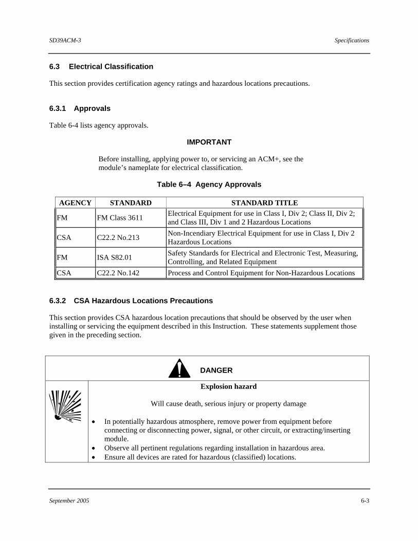
SD39ACM-3 Specifications
September 2005 6-3
6.3 Electrical Classification
This section provides certification agency ratings and hazardous locations precautions.
6.3.1 Approvals
Table 6-4 lists agency approvals.
IMPORTANT
Before installing, applying power to, or servicing an ACM+, see the module’s nameplate for electrical classification.
Table 6–4 Agency Approvals
AGENCY STANDARD STANDARD TITLE
FM FM Class 3611 Electrical Equipment for use in Class I, Div 2; Class II, Div 2; and Class III, Div 1 and 2 Hazardous Locations
CSA C22.2 No.213 Non-Incendiary Electrical Equipment for use in Class I, Div 2 Hazardous Locations
FM ISA S82.01 Safety Standards for Electrical and Electronic Test, Measuring, Controlling, and Related Equipment
CSA C22.2 No.142 Process and Control Equipment for Non-Hazardous Locations
6.3.2 CSA Hazardous Locations Precautions
This section provides CSA hazardous location precautions that should be observed by the user when installing or servicing the equipment described in this Instruction. These statements supplement those given in the preceding section.
DANGER
Explosion hazard
Will cause death, serious injury or property damage • In potentially hazardous atmosphere, remove power from equipment before
connecting or disconnecting power, signal, or other circuit, or extracting/inserting module.
• Observe all pertinent regulations regarding installation in hazardous area. • Ensure all devices are rated for hazardous (classified) locations.

Specifications SD39ACM-3
6-4 September 2005
SD39ACM-3 Specifications
September 2005 6-5
Precautions - English
For Class I, Division 1 and Class I, Division 2 hazardous locations:
Use only factory-authorized replacement parts. Substitution of components can impair the suitability of this equipment for hazardous locations.
For Division 2 hazardous locations:
When the equipment described in this Instruction in installed without safety barriers, the following precautions should be observed. Switch off electrical power at its source (in non-hazardous location) before:
• Connecting or disconnecting power, signal, or other wiring • Replacing a fuse, circuit board, or any other component connected to the electrical circuit
Précautions - Français
Emplacements dangereux de classe I, division 1 et classe I, division 2:
Les pièces de rechange doivent être autorisées par l'usine. Les substitutions peuvent rendre cet appareil impropre à l'utilisation dans les emplacements dangereux.
Emplacement dangereux de division 2:
Lorsque l'appareil décrit dans la notice ci-jointe est installé sans barrières de sécurité, on doit couper l'alimentation électrique a la source (hors de l'emplacement dangereux) avant d'effectuer les opérations suivantes:
• Branchment ou débranchement d'un circuit de puissance, de signalisation ou autre • Replacement d'un fusible, d'une carte de circuit imprimé ou de tout autre élément connecté au circuit
électrique.
6.4 Electromagnetic Compatibility (EMC)
This product has been tested per the European Union’s EMC Directive. See the Declaration of Conformity statement at the back of this Instruction. Refer to Section 2.1.2 for considerations affecting EMC compliance.
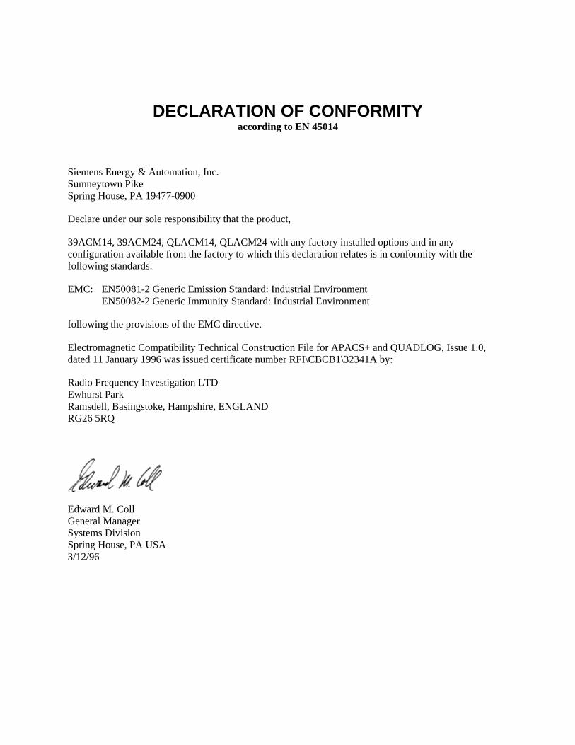
DECLARATION OF CONFORMITY according to EN 45014
Siemens Energy & Automation, Inc. Sumneytown Pike Spring House, PA 19477-0900
Declare under our sole responsibility that the product,
39ACM14, 39ACM24, QLACM14, QLACM24 with any factory installed options and in any configuration available from the factory to which this declaration relates is in conformity with the following standards:
EMC: EN50081-2 Generic Emission Standard: Industrial Environment EN50082-2 Generic Immunity Standard: Industrial Environment
following the provisions of the EMC directive.
Electromagnetic Compatibility Technical Construction File for APACS+ and QUADLOG, Issue 1.0, dated 11 January 1996 was issued certificate number RFI\CBCB1\32341A by:
Radio Frequency Investigation LTD Ewhurst Park Ramsdell, Basingstoke, Hampshire, ENGLAND RG26 5RQ
Edward M. Coll General Manager Systems Division Spring House, PA USA 3/12/96