Embed Size (px)
Citation preview
www.siemens.com/plm
White PaperIncorporating the benefits of 2D and 3D design technologies into a single effective design approach, enabling the use of the right tool for the right job at hand while continuing to keep all geometry in sync.
Siemens PLM Software
Hybrid 2D/3D designThe right tool for the right job at the right time
1A white paper issued by: Siemens PLM Software.

White paper | Hybrid 2D/3D design
A white paper issued by: Siemens PLM Software. 2
Contents
Introduction .....................................................................3
Hybrid 2D/3D design ........................................................4
Working in 2D ..................................................................5
Turning 2D geometry into 3D parts ..................................6
Working with hybrid 2D/3D geometry ..............................7
Zero D Design with virtual components ...........................8Defining a virtual structure.................................................8Associating design data .....................................................8Creating the hybrid 2D/3D model .......................................9
Full 3D design ................................................................10
Conclusion .....................................................................11
White paper | Hybrid 2D/3D design
A white paper issued by: Siemens PLM Software. 3
IntroductionThe advantages of designing in 3D are well documented. The complete development process can benefit from improved communication and visualization, a reduction in design errors, elimination of costly physical prototypes, faster design changes, increased re-use of proven designs, accelerated downstream processes and the list goes on.
And yet, it has been estimated that 80 percent of CAD users still do some or all of their work in 2D. Why is this? Many companies recognize that, in reality, good engineering design needs a mixture of both 2D and 3D to function to its full potential and that standalone 2D remains a crucial development step. There are dozens of instances in design development when you want a 2D approach and not a 3D model. These 2D steps rarely involve manufacture or prototype production. They are merely an aid to thinking about the problem.
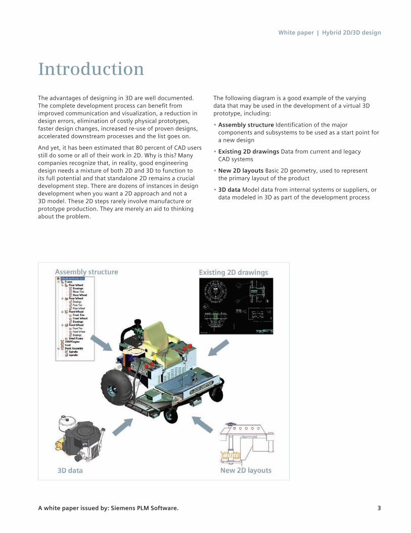
The following diagram is a good example of the varying data that may be used in the development of a virtual 3D prototype, including:
• Assembly structure Identification of the major components and subsystems to be used as a start point for a new design
• Existing 2D drawings Data from current and legacy CAD systems
• New 2D layouts Basic 2D geometry, used to represent the primary layout of the product
• 3D data Model data from internal systems or suppliers, or data modeled in 3D as part of the development process
White paper | Hybrid 2D/3D design
A white paper issued by: Siemens PLM Software. 4
Hybrid 2D/3D designIt is clear then, that product development must be able to utilize these varying data types in a practical and logical manner. This document explores Solid Edge® software’s unique 2D/3D hybrid approach to design, an approach borne out of the understanding that the use of 3D software only makes sense if all the design stages, including early 2D thoughts and layouts, can be linked from concept to finished product.
With this approach, organizations can think more about their complete development process to decide where and when 2D or 3D is relevant and choose the right discipline for each part.
We’ll begin by taking a look at the specific tools that Solid Edge provides for working with 2D data, and continue through a typical workflow for developing a hybrid 2D/3D design. As we develop the design, it will become clear that Solid Edge hybrid approach offers benefits for two distinct groups of users, each with similar goals but requiring differ-ent paths to reach them:
• 2D users can leverage productive 2D activities, thought processes and designs to evolve smoothly to 3D without jeopardizing their business. Solid Edge has clearly established itself as having the best 2D to 3D migration strategy in the industry today. With its 4 step “Evolve to 3D” program*, customers can migrate to 3D on their own terms applying a hybrid 2D/3D design methodology which is both low risk and efficient. Many customers have upgraded to Solid Edge from 2D solutions, and their feedback has been invaluable in the development of practical tools and a smooth workflow.
• Experienced 3D users can carry out any relevant upfront work such as machine layouts in 2D, and mix and match 2D and 3D as and when it makes sense for the development of the design.
You will see that, although these tools directly relate to the differing needs of these two groups, there is a significant overlap, which is understandable. Most importantly, Solid Edge gives both groups a design system that allows them to use of the right tool for the right job at the right time.
* Visit www.siemens.com/solidedge for more information.
White paper | Hybrid 2D/3D design
A white paper issued by: Siemens PLM Software. 5
Working in 2DCompanies designing with 2D software are concerned about their legacy data, and rightly so. With Solid Edge, your past investment is safe. Solid Edge provides a unique, simple approach that provides the means to get all of the benefits of 3D CAD by leveraging productive 2D activities, thought processes and designs, without creating unnecessary confu-sion within an organization.
Solid Edge will read and write existing 2D files (AutoCAD DWG/DXF, Mechanical Desktop, MicroStation DGN, IGES 2D) using automated translation wizards that offer complete user control over line styles, dimensions, fonts and layers. Solid Edge automatically recognizes and sets the view scale and paper size for translated drawings.
To further help companies transitioning from AutoCad, Solid Edge has options for 2D drawings to display as they did in AutoCAD, so they can be maintained using efficient Solid Edge 2D drawing tools while retaining a familiar look and feel to the original.
Solid Edge also includes exceptional standalone 2D drafting capabilities so you can continue to maintain your existing data – editing and updating translated drawings, adding new 2D geometry and annotation and even adding increased intelligence to existing 2D geometry and dimensions. And the commands you became familiar with in 2D are just as relevant and useful in 3D, so you won’t have the disruption of having to learn a completely new approach later.
These 2D drafting tools not only emulate the workflows you already know but offer additional capabilities as well. For
example, you can set up and display a very flexible grid to help with sketching. Projection lines are available to help with creating 2D views. But, rather than creating additional lines which need to be deleted or moved to different layers, Solid Edge project lines are a property of the actual geometry and can be simply turned on or off as required.
Solid Edge also provides a familiar process for generating detail drawings from 2D layouts. Similar in concept to the model and paper space methodology in other 2D products, you develop 2D layouts at 1:1 scale and then create multiple detail views of the layout on separate drawing sheets. Each view can be scaled as required, while still maintaining correct dimensions and annotations.
It is also worth noting that most of these capabilities are also available in 3D. So, for example, grids, projection lines and layer schemes can all be used in the profile environment when modeling parts.
Many companies have automated their existing 2D applica-tion with Macros for common procedures such as creating hole tables or bills of material (BOM). Although the inherent nature of 3D means that most of these macros are no longer necessary, the Solid Edge API does make it possible to convert any required macros to Visual Basic and customize Solid Edge to do the same job.
Solid Edge remains the only system to offer complete 2D and 3D design tools in a single system.
White paper | Hybrid 2D/3D design
A white paper issued by: Siemens PLM Software. 6
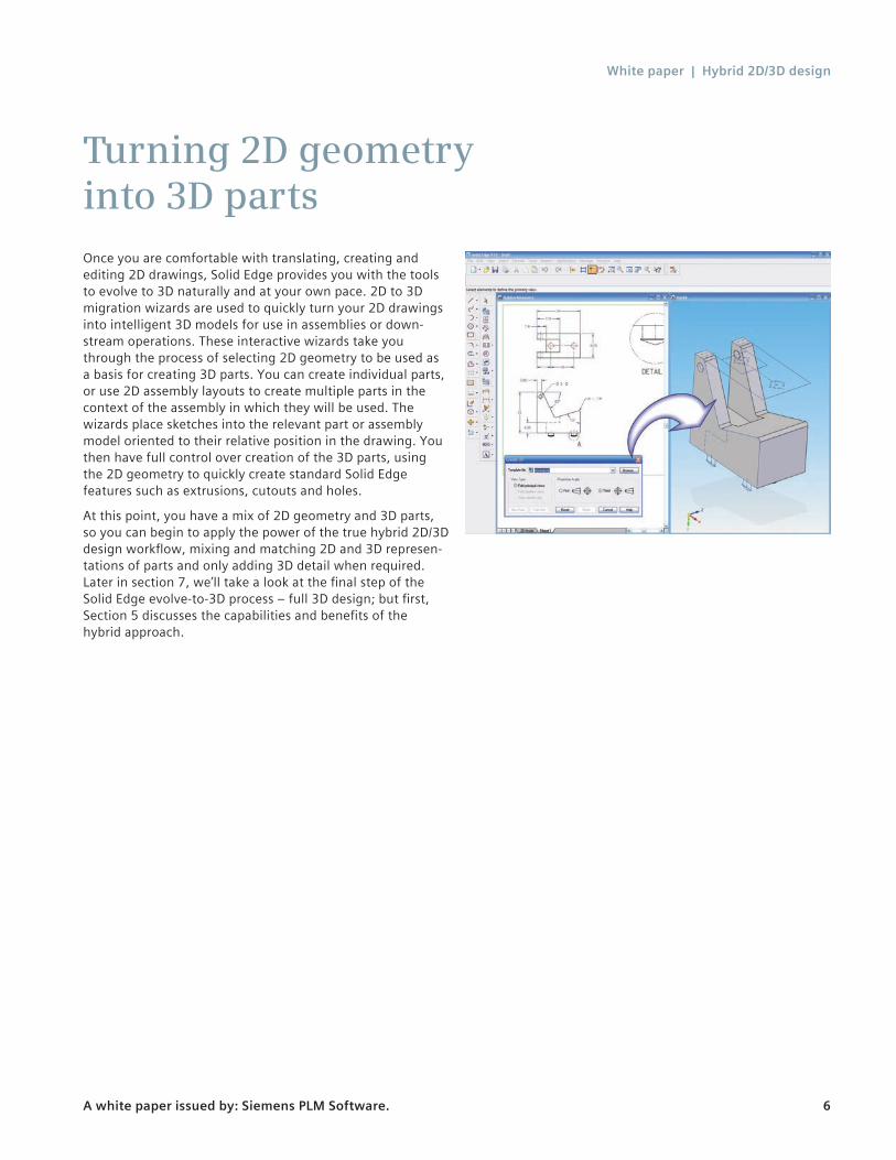
Turning 2D geometry into 3D partsOnce you are comfortable with translating, creating and editing 2D drawings, Solid Edge provides you with the tools to evolve to 3D naturally and at your own pace. 2D to 3D migration wizards are used to quickly turn your 2D drawings into intelligent 3D models for use in assemblies or down-stream operations. These interactive wizards take you through the process of selecting 2D geometry to be used as a basis for creating 3D parts. You can create individual parts, or use 2D assembly layouts to create multiple parts in the context of the assembly in which they will be used. The wizards place sketches into the relevant part or assembly model oriented to their relative position in the drawing. You then have full control over creation of the 3D parts, using the 2D geometry to quickly create standard Solid Edge features such as extrusions, cutouts and holes.
At this point, you have a mix of 2D geometry and 3D parts, so you can begin to apply the power of the true hybrid 2D/3D design workflow, mixing and matching 2D and 3D represen-tations of parts and only adding 3D detail when required. Later in section 7, we’ll take a look at the final step of the Solid Edge evolve-to-3D process – full 3D design; but first, Section 5 discusses the capabilities and benefits of the hybrid approach.

White paper | Hybrid 2D/3D design
A white paper issued by: Siemens PLM Software. 7
Working with hybrid 2D/3D geometryWith a mix of 2D geometry and 3D parts, you can now begin to apply the power of the true hybrid 2D/3D design work-flow, solving 3D problems using 2D geometry and using 2D geometry to drive the shape and position of 3D parts.
If you are working in team environment, a significant advantage of the hybrid approach is the ability to distribute the assembly layout, assigning 2D geometry to specific components and sub-assemblies, while keeping each of them associated to the overall project. Team members will be automatically updated when others make changes to either 2D geometry or 3D parts, eliminating any surprises when the final project reaches manufacturing.
With the 2D layout distributed as necessary, you can begin to use the geometry to create 3D models using the Solid Edge wizards. By keeping the geometry associative, the shape of 3D components will continue to be driven from the 2D assembly layout. Or you can remove the associativity and work separately with the 3D models.
If you already have 3D models to use on the project, you can drag and drop them into the product layout, controlling their position by adding relationships (dimensions) to the 2D geometry, using single or multiple views. Dimensions can be placed to intelligent “inferred” geometry, such as a 3D axis representing the centerline of a hole circle, and you can orient parts at compound angles by adding dimensional constraints in multiple views. This combination of adding constraints from the surfaces of the 3D model to the sketches, and driving geometry in both directions, allows you check fit. 3D assembly range of motion can be analyzed by making changes to the 2D assembly layout, and practi-cally solve 3D problems without having to build a complete 3D prototype.
White paper | Hybrid 2D/3D design
A white paper issued by: Siemens PLM Software. 8
Zero D Design with virtual componentsThe previous sections clearly demonstrate Solid Edge capabilities in working with product design data that is a mix of 2D geometry and 3D models. While the benefits of this approach are obvious, most product design processes begin with a definition stage before any of this geometry exists. A lead engineer may define the assembly structure; identifying major components and subsystems to be used as a start point for a new design. Part numbers may be reserved, and other nongraphic information referenced, such as materials, supplier names or estimated costs. But, at this point it is a structure only. You may have some legacy 2D data, concep-tual sketches may have been developed, some new 3D models may have been created, or existing 3D models may have been identified as potentially being repurposed for the new design. But no formal design work has begun. This is exactly why Solid Edge introduced its “Zero D” capability, giving a workflow that matches a typical product design process. With Zero D, you can define the key elements of a product structure before any geometry is committed to paper.
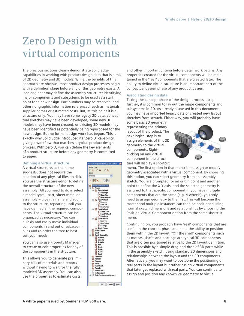
Defining a virtual structureA virtual structure, as the name suggests, does not require the creation of any physical files on disk. You use the structure editor to define the overall structure of the new assembly. All you need to do is select a model type – part, sheet metal or assembly – give it a name and add it to the structure, repeating until you have defined all the required compo-nents. The virtual structure can be organized as necessary. You can quickly and easily move individual components in and out of subassem-blies and re-order the tree to best suit your needs.
You can also use Property Manager to create or edit properties for any of the components in the structure.
This allows you to generate prelimi-nary bills of materials and reports without having to wait for the fully modeled 3D assembly. You can also use the properties to estimate costs
and other important criteria before detail work begins. Any properties created for the virtual components will be main-tained in the “real” components that are created later. The ability to define virtual structure is an important part of the conceptual design phase of any product design.
Associating design dataTaking the concept phase of the design process a step further, it is common to lay out the major components and subsystems in 2D. As already discussed in this document, you may have imported legacy data or created new layout sketches from scratch. Either way, you will probably have some basic 2D geometry representing the primary layout of the product. The next logical step is to assign elements of this 2D geometry to the virtual components. Right-clicking on any virtual component in the struc-ture will display a shortcut menu. The first option in that menu is to assign or modify geometry associated with a virtual component. By choosing this option, you can select geometry from an assembly sketch. You are prompted for an origin point and another point to define the X-Y axis, and the selected geometry is assigned to that specific component. If you have multiple components that are the same (e.g. 4 wheels), you only need to assign geometry to the first. This will become the master and multiple instances can then be positioned using normal sketch dimensions and relationships by choosing the Position Virtual Component option from the same shortcut menu.
Continuing on, you probably have “real” components that are useful in the concept phase and need the ability to position them within the 2D layout. “Off the shelf” components such as motors, shafts and bearings are typical 3D components that are often positioned relative to the 2D layout definition. This is possible by a simple drag-and-drop of 3D parts while in the assembly sketch, using standard 2D dimensions and relationships between the layout and the 3D components. Alternatively, you may want to postpone the positioning of real parts in the layout but rather assign virtual components that later get replaced with real parts. You can continue to assign and position any known 2D geometry to virtual
White paper | Hybrid 2D/3D design
A white paper issued by: Siemens PLM Software. 9
components and work with the 2D layouts to validate the structure. At this point, no physical files for the virtual components have been created on disk and real components are simply re-used.
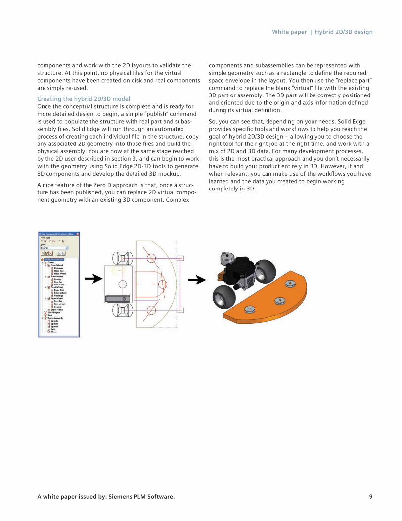
Creating the hybrid 2D/3D modelOnce the conceptual structure is complete and is ready for more detailed design to begin, a simple “publish” command is used to populate the structure with real part and subas-sembly files. Solid Edge will run through an automated process of creating each individual file in the structure, copy any associated 2D geometry into those files and build the physical assembly. You are now at the same stage reached by the 2D user described in section 3, and can begin to work with the geometry using Solid Edge 2D-3D tools to generate 3D components and develop the detailed 3D mockup.
A nice feature of the Zero D approach is that, once a struc-ture has been published, you can replace 2D virtual compo-nent geometry with an existing 3D component. Complex
components and subassemblies can be represented with simple geometry such as a rectangle to define the required space envelope in the layout. You then use the “replace part” command to replace the blank “virtual” file with the existing 3D part or assembly. The 3D part will be correctly positioned and oriented due to the origin and axis information defined during its virtual definition.
So, you can see that, depending on your needs, Solid Edge provides specific tools and workflows to help you reach the goal of hybrid 2D/3D design – allowing you to choose the right tool for the right job at the right time, and work with a mix of 2D and 3D data. For many development processes, this is the most practical approach and you don’t necessarily have to build your product entirely in 3D. However, if and when relevant, you can make use of the workflows you have learned and the data you created to begin working completely in 3D.

White paper | Hybrid 2D/3D design
A white paper issued by: Siemens PLM Software. 10
Full 3D designAlthough beyond the scope of this document, Solid Edge provides hundreds of exceptional tools for creating and managing complete 3D digital prototypes. With superior core modeling and process workflows, a unique focus on the needs of specific industries and fully integrated design management, Solid Edge helps guide your projects toward an error free, accurate design solution.
Solid Edge modeling and assembly tools enable your engi-neering team to easily develop a full range of products, from single parts to assemblies containing thousands of compo-nents. Tailored commands and structured workflows acceler-ate the design of features common in specific industries, and you ensure accurate fit of parts by designing, verifying and
modifying them within the assembly model. With Solid Edge, your products come together right first time, every time.
Solid Edge merges excellent design management capabilities with the CAD tools that designers use every day. Solid Edge™ SP design management solution provides a visual approach to design management for design departments and enables related technical documents to be easily managed alongside Solid Edge documents. For users requiring full product lifecy-cle management (PLM) capabilities, Solid Edge integrates seamlessly with Teamcenter® software enabling Solid Edge documents to be captured into a comprehensive PLM environment.
White paper | Hybrid 2D/3D design
A white paper issued by: Siemens PLM Software. 11
ConclusionThe benefits of 3D design are well known, but many design processes follow a workflow of first establishing a basic product structure, utilizing new and existing 2D layouts to create a concept and moving to 3D only when appropriate. Solid Edge 2D/3D hybrid design capabilities encapsulate this valuable workflow, giving you the flexibility to choose the approach that best suits each individual step in your develop-ment process and allowing you to adapt to varying design data and supporting information that you have available at the time.
Product and process complexity is a growing concern for manufacturing organizations, and thousands around the world have come to rely on Solid Edge to battle this increas-ing complexity head-on. Complexity is significantly eased when the right tools are available at the right time. Good engineering design needs a mixture of both 2D and 3D to function to its full potential, and with Solid Edge you have the means to reach and exceed that potential.
White paper | Hybrid 2D/3D design
A white paper issued by: Siemens PLM Software. 12
www.siemens.com/plm © 2014 Siemens Product Lifecycle Management Software Inc. Siemens and the Siemens logo are registered trademarks of Siemens AG. D-Cubed, Femap, Fibersim, Geolus, GO PLM, I-deas, JT, NX, Parasolid, Quality Planning Environment, Solid Edge, Syncrofit, Teamcenter and Tecnomatix are trademarks or registered trademarks of Siemens Product Lifecycle Management Software Inc. or its subsidiaries in the United States and in other countries. Nastran is a registered trade-mark of the National Aeronautics and Space Administration. All other logos, trademarks, registered trademarks or service marks belong to their respective holders. 4172-Y3 8/14 C
Siemens PLM Software Headquarters Granite Park One 5800 Granite Parkway Suite 600 Plano, TX 75024 USA +1 972 987 3000 Americas Granite Park One 5800 Granite Parkway Suite 600 Plano, TX 75024 USA +1 314 264 8287 Europe Stephenson House Sir William Siemens Square Frimley, Camberley Surrey, GU16 8QD +44 (0) 1276 413200 Asia-Pacific Suites 4301-4302, 43/F AIA Kowloon Tower, Landmark East 100 How Ming Street Kwun Tong, Kowloon Hong Kong +852 2230 3308
About Siemens PLM SoftwareSiemens PLM Software, a business unit of the Siemens Industry Automation Division, is a world-leading provider of product lifecycle management (PLM) software, systems and services with nine million licensed seats and 77,000 customers worldwide. Headquartered in Plano, Texas, Siemens PLM Software helps thousands of companies make great products by optimizing their lifecycle processes, from planning and development through manufacturing and support. Our HD-PLM vision is to give everyone involved in making a product the information they need, when they need it, to make the smartest decisions. For more informa-tion on Siemens PLM Software products and services, visit www.siemens.com/plm.