Embed Size (px)
Citation preview
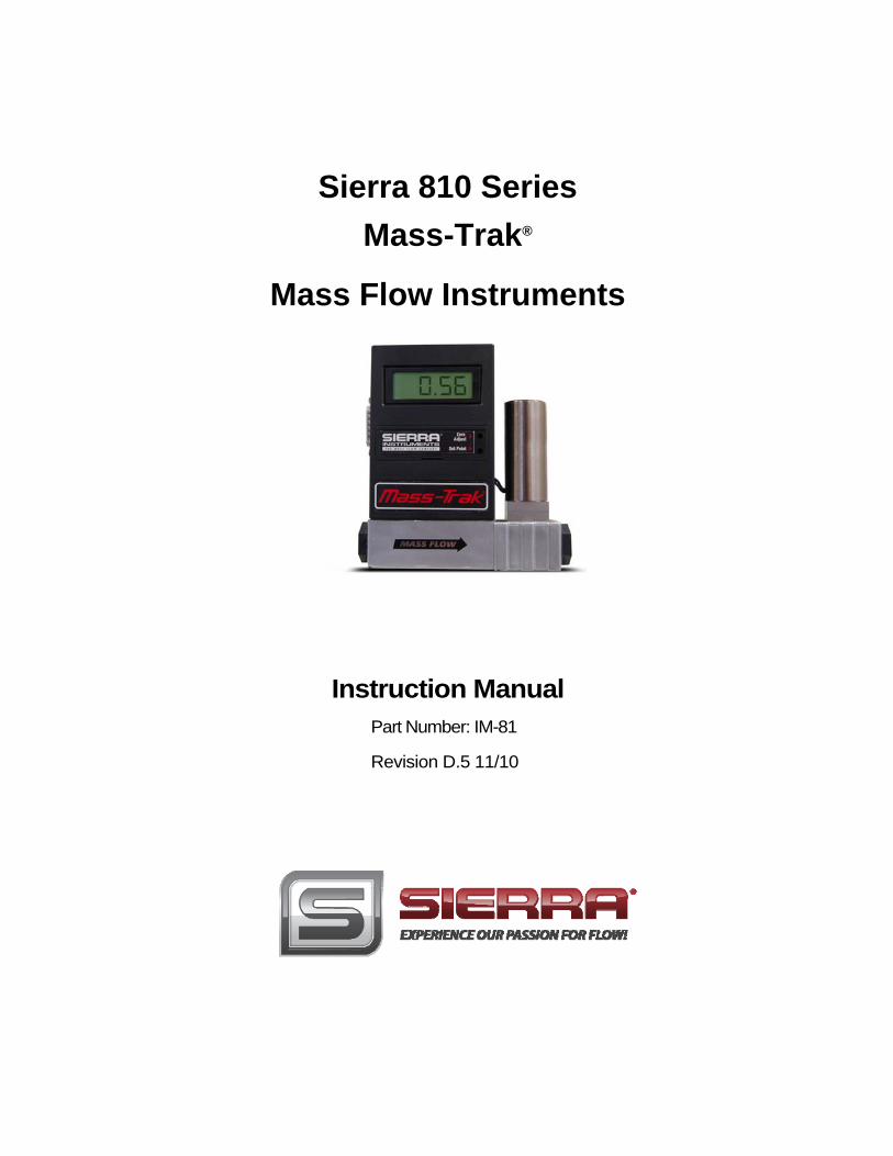
Sierra 810 Series Mass-Trak®
Mass Flow Instruments
Instruction Manual Part Number: IM-81
Revision D.5 11/10
GLOBAL SUPPORT LOCATIONS: WE ARE HERE TO HELP!
CORPORATE HEADQUARTERS 5 Harris Court, Building L Monterey, CA 93940 Phone (831) 373-0200 (800) 866-0200 Fax (831) 373-4402 www.sierrainstruments.com
EUROPE HEADQUARTERS Bijlmansweid 2 1934RE Egmond aan den Hoef The Netherlands Phone +31 72 5071400 Fax +31 72 5071401
ASIA HEADQUARTERS Rm. 618, Tomson Centre, Bldg A, 188 Zhang Yang Road Pu Dong New District, Shanghai, P.R. China Phone: + 8621 5879 8521 Fax: +8621 5879 8586
IMPORTANT CUSTOMER NOTICE: OXYGEN SERVICE
Sierra Instruments, Inc. is not liable for any damage or personal injury, whatsoever, resulting from the use of Sierra Instruments standard mass flow meters or controllers for oxygen gas. You are responsible for determining if this mass flow meter or controller is appropriate for your oxygen application. You are responsible for cleaning the mass flow meter or controller to the degree required for your oxygen flow application.
© COPYRIGHT SIERRA INSTRUMENTS 2010 No part of this publication may be copied or distributed, transmitted, transcribed, stored ina retrieval system, or translated into any human or computer language, in any form or byany means, electronic, mechanical, manual, or otherwise, or disclosed to third partieswithout the express written permission of Sierra Instruments. The information contained inthis manual is subject to change without notice. TRADEMARKS
Max-Trak® 810 Series is a Registered Trademark of Sierra Instruments, Inc. Otherproduct and company names listed in this manual are trademarks or trade names of theirrespective manufacturers.
Series 810 Table of Contents
TABLE OF CONTENTS
Chapter 1 Introduction
Introduction ................................................. 1-1Using this Manual ................................... 1-2Safety Information ............................... 1-3Receipt of System Components ......... 1-3Technical Assistance ............................. 1-3
The 810 Series Flow Sensing Principle 1-4
Chapter 2 Installation
Installation Overview ..................................... 2-1Before Beginning an Installation..................................... 2-1Installing the Transducer (Plumbing) ........... 2-2
Compression Fittings ........................... 2-2VCO Fittings ........................................ 2-3VCR Fittings ......................................... 2-31/4-inch Female NPT Fittings ............. 2-3
Installing the Transducer (Electrical) ........... 2-4D-connector PIN assignments ............. 2-5
Chapter 3 Operation
Mass Flow Meter Operation ......................... 3-1Mass Flow Controller Operation ................... 3-1
Setpoint Adjustment ............................... 3-2Setpoint Configuration ............................ 3-3Over-Range Condition ........................... 3-4Auto Shut-Off Function ....................... 3-5Manual Valve Override ....................................... ... 3-5ValvePurge........................... ............................. 3-5
Chapter 4 Maintenance
Flow Path Maintenance and Cleaning 4-1Sensor Maintenance and Inspection ......... 4-2Valve Maintenance ........................................ 4-3
Valve Adjustment Procedure ................. 4-4Transducer Calibration ................................. 4-5
Chapter 5 Troubleshooting
Transducer Troubleshooting Charts ........... 5-1Returning Equipment to the Factory ............ 5-2
Table of Contents Series 810
Appendix A Conversion Formulas and Gas Tables
Calculations.............................. ... ............................A-1
Gas Tables with K-factors .............................................A-5
Appendix B Product Specifications
Operating Specifications .................. .... ............................B-1
Performance Specifications ............... ..... ............................B-2
Physical Specifications .................... .... ............................B-2
Mounting Dimensions (Nylon Body) ... ...... ............................B-3
Dimensions—Stainless Steel Low Flow Body.......... ...... ...... B-4
Dimensions—Stainless Steel Medium Flow Body .................B-5
Appendix C Pin Connections
Appendix D Purge and Valve Off Connections
List of Figures
1-1. Mass-Trak Features (Typical) ............................... 1-1
1-2. Flow Paths through the Transducer .................... 1-4
1-3. Flow Measuring Principle ..................................... 1-4
1-4 Sensor Temperature Distribution .... . . . . . . . . . . . .. . . . . . . . . . . . . . . . ...1-5
1-5 Linear Range of Transducer Output Signal .........................1-5
2-1. Minimum Restriction Diameters ..................................................... 2-4
2-2. Transducer D-Connector Pin Assignments ................................. 2-5
3-1 Dip Switch Settings.................................................... 3-3
4-1. Stainless Steel Low Flow Internals ............................................ 4-2
4-2. Stainless Steel Medium Flow Internals ....................................... 4-2
4-3. Nylon Transducer Internals ......................................................... 4-2

Series 810 Instruction Manual Chapter 1 Introduction
Chapter 1 Introduction
Sierra's Mass-Trak' mass flow meters and controllers are designed
to accurately measure and control flows of process gases. This
instruction manual covers the installation, operation and maintenance
of the Mass-Trak product line, which includes the following Sierra
models:
• Model 810M Mass-Trak Flow Meter
• Model 810C Mass-Trak Flow Controller
• Model 810S-L Mass-Trak Flow Controller for flows up to 15
SLPM
• Model 810S-M Mass-Trak Flow Controller for flows from 15
to 100 SLPM
All of these models can be ordered with or without a digital
display.
Sierra Instruments' Series 810 Mass-Trak products can be calibrated to measure and control the mass flow rate of gases in several ranges from 0-10 standard cubic centimeters per minute (SCCM) to 0-100 standard liters per minute (SLPM). Accuracy is ±1.5% of full scale over a wide temperature and pressure range, and time response is 5 seconds to within 2% of set point. Detailed product specifications may be found in Appendix B.
Mass -Trak Design (typical)
Figure 1-1. Mass-Trak Design (typical)
Mass-Trak is ideally suited to a wide range of gas flow applications
including general process control, laboratories, instrument OEM's,
gas panels, and flow calibration.
FLOW
ZERO
SET POINT
IM-81-D 1-1
Chapter 1 Introduction Series 810 Instruction Manual
Mass-Trak requires a regulated 24 VDC external power source. The
0-5 VDC and 4-20 mA output signals, which are linearly
proportional to gas mass flow rate, are provided for recording, data
logging, or control. A 15-pin "D" connector is provided for power
input, output signal and set point control. Mass-Trak is available in
a variety of configurations with either a nylon or stainless steel flow
body. A 24VDC power supply is available as an option.
Using This Manual
This manual is organized into five chapters:
• Chapter 1 includes the introduction and theory of operation
• Chapter 2 provides installation, plumbing and wiring instructions
• Chapter 3 describes operation and features
• Chapter 4 covers routine maintenance
• Chapter 5 contains the troubleshooting guide and service
recommendations
There are also 4 Appendices:
• Appendix A lists conversion formula and gas tables
• Appendix B includes the product specifications, dimensional drawings and mounting instructions
• Appendix C describes the PIN connections
• Appendix D describes the purge and valve off connections
Throughout this manual, we use the word transducer as a generic
term to represent all models of Sierra's 810 Series Mass-Trak
instruments.
1-2 IM-810-D
Series 810 Instruction Manual Chapter 1 Introduction
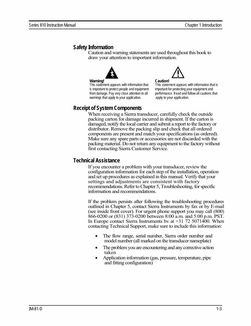
Safety Information
Caution and warning statements are used throughout this book to
draw your attention to important information.
Warning! Caution!
This statement appears with information that This statement appears with information that is
is important to protect people and equipment important for protecting your equipment and
from damage. Pay very close attention to all performance. Read and follow all cautions that
warnings that apply to your application. apply to your application.
Receipt of System Components
When receiving a Sierra transducer, carefully check the outside
packing carton for damage incurred in shipment. If the carton is
damaged, notify the local carrier and submit a report to the factory or
distributor. Remove the packing slip and check that all ordered
components are present and match your specifications (as ordered).
Make sure any spare parts or accessories are not discarded with the
packing material. Do not return any equipment to the factory without
first contacting Sierra Customer Service.
Technical Assistance
If you encounter a problem with your transducer, review the
configuration information for each step of the installation, operation
and set up procedures as explained in this manual. Verify that your
settings and adjustments are consistent with factory
recommendations. Refer to Chapter 5, Troubleshooting, for specific
information and recommendations.
If the problem persists after following the troubleshooting proceduresoutlined in Chapter 5, contact Sierra Instruments by fax or by E-mail(see inside front cover). For urgent phone support you may call (800)866-0200 or (831) 373-0200 between 8:00 a.m. and 5:00 p.m. PST.In Europe contact Sierra Instruments bv at +31 72 5071400. Whencontacting Technical Support, make sure to include this information:
• The flow range, serial number, Sierra order number and
model number (all marked on the transducer nameplate)
• The problem you are encountering and any corrective action
taken
• Application information (gas, pressure, temperature, pipe
and fitting configuration)
IM-81-D 1-3
Chapter 1 Introduction Series 810 Instruction Manual
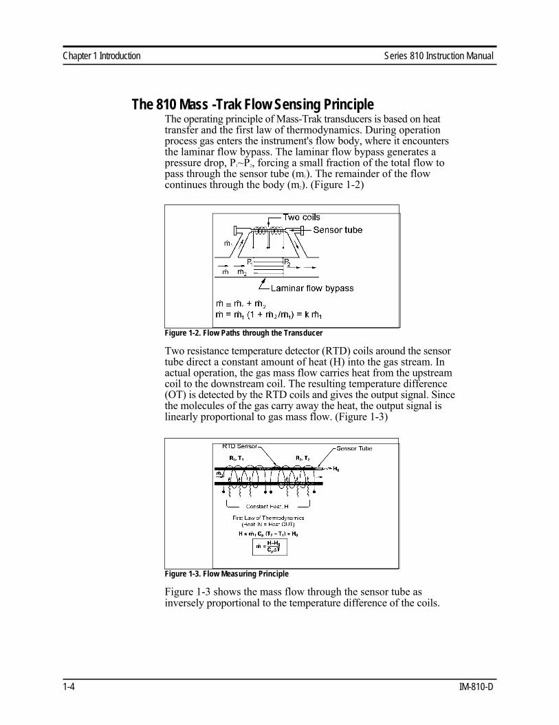
The 810 Mass -Trak Flow Sensing Principle
The operating principle of Mass-Trak transducers is based on heat transfer and the first law of thermodynamics. During operation process gas enters the instrument's flow body, where it encounters the laminar flow bypass. The laminar flow bypass generates a pressure drop, P1~P2, forcing a small fraction of the total flow to pass through the sensor tube (m1). The remainder of the flow continues through the body (m2). (Figure 1-2)
Figure 1-2. Flow Paths through the Transducer
Two resistance temperature detector (RTD) coils around the sensor tube direct a constant amount of heat (H) into the gas stream. In actual operation, the gas mass flow carries heat from the upstream coil to the downstream coil. The resulting temperature difference (OT) is detected by the RTD coils and gives the output signal. Since the molecules of the gas carry away the heat, the output signal is linearly proportional to gas mass flow. (Figure 1-3)
Figure 1-3. Flow Measuring Principle
Figure 1-3 shows the mass flow through the sensor tube as inversely proportional to the temperature difference of the coils.
1-4 IM-810-D

Series 810 Instruction Manual Chapter 1 Introduction
Figure 1-4. Sensor Temperature Distribution
The RTD coils are legs of a bridge circuit with an output voltage in
direct proportion to the difference in the coils' resistance; the result is
the temperature difference (OT), Figure 1-4. Two other parameters,
heat input (H) and coefficient of specific heat (Cp) are both constant.
The resulting output is nearly linear over the transducer's normal
operating range (Figure 1-5).
Figure 1-5. Linear Range of the Transducer's Output Signal
For mass flow controllers, once the gas flows through the
monitoring section, it is then controlled by the built-in servo-control
valve. All models of the Mass-Trak utilize Sierra's proprietary high- efficiency Fast-Trak Electromagnetic Valve. The normally closed
Fast-Trak valve is similar to an on/off solenoid valve, except that the
current to the valve coil, and hence the magnetic field, is modulated
so that the ferromagnetic valve armature, or valve plug, assumes the
exact height above the valve's orifice required to maintain the
valve's command flow. The result is nearly infinite resolution.
IM-81-D 1-5

Series 810 Instruction Manual Chapter 2 Installation
Chapter 2 Installation
Installation Overview
Mass-Trak- transducers are supplied with female NPT, compression,
VCO, or VCR process connections. To ensure a successful installation,
inlet and outlet tubing should be in a clean state prior to plumbing the
transducer into the system. The shipping caps covering the inlet/outlet
fittings should not be removed until immediately prior to installation.
Before Beginning the Installation
Before installing the transducer, verify the following:
1. Ensure that the installation site conforms to the specific operating p a rameters r e corded on the transducer's nameplate. This is critical as
each transducer is factory-configured for a specific gas and flow range,
pressure differential, temperature range and mounting orientation. The
line pressure should not exceed the upper limit for the model in hand:
150 psig (Models 810M, 810C), 500 psig (Model 810S-M) or 1000
psig (Model 810S-L). The temperature should not exceed 122°F
(50°C).
2. Double-check to be sure that the transducer o-ring material is compatible
with the gas to be measured.
3. If the gas contains any particulate matter, install an in-line filter
upstream of the transducer. Recommended filter size: 15 micron for
flows of 10 to 30 slpm, 30 micron for flows above 30 slpm.
4. Do not locate the transducer in areas subject to sudden temperature
changes, excessive moisture, frequent drafts or near equipment
radiating significant amounts of heat. Be sure to allow adequate space
for cable connectors and wiring.
5. Ensure the installation location provides a minimum of two inches of
straight pipe upstream and downstream from the process connections.
6. For controllers, use a properly sized pressure regulator and verify that
the controller orifice size is the smallest in the system. There can be no
restrictions (such as valves, tubing or pipe internal diameters, reducers,
etc.) upstream or downstream of the controller with a dimension that is
less than the valve orifice diameter.
7. Output Signals: The Mass-Trak has 0-5 VDC (0-10 VDC optional) and
4-20 mA output signals that are linearly proportional to the gas mass
flow rate. The instrument was calibrated using either voltage or current
output as specified on the data tag. Note that there may be a slight
difference between the voltage and the current output signals (up to
IM-81-D 2-1

Chapter 2 Installation Series 810 Instruction Manual
Caution!
Only qualified
personnel should
install the transducer.
1 %). Using the output that is recorded on the data tag will optimize
instrument performance.
8. Integral Display: The 3 1/2 digit LCD display reads directly in
engineering units or percent of full scale. The full-scale range and gas
are shown on the instrument data tag. The decimal point for the flow
rate is set at the factory and will show automatically (e.g., "5.54" SLM or "76.4" %).
9. Over range conditions are indicated by the display and/or output going
to a high level, approximately 150% of the full-scale range. After the
over-range condition has been removed, it may take several minutes for
the Mass-Trak to recover and resume normal operation.
10. The transducer has stringent power supply requirements. Because the
valve on flow controllers is operated in a control loop, power supply
variations cannot be tolerated. See Appendix B for a complete listing of
power requirements.
Installing the Transducer-Plumbing
Follow the installation instructions that are applicable to your
transducer's process connection. Before use, all plumbing should be
checked carefully for leaks and the transducer should be purged with
dry nitrogen. Ensure that the tubing is free from burrs, or sharp rims
that may result from cutting.
CAUTION: All instruments are leak-tested prior to shipping. To
check your installation, test the fittings only. Do not use liquid leak
detectors such as Snoop® to search for leaks inside or outside the
Mass-Trak. Instead, monitor pressure decay.
Compression Fittings
1. Position the transducer with the flow
direction arrow pointing in the direction of
flow.
2. Verify the position of the front and back
ferrule as shown above. Insert the tubing into the fitting. Be sure
that the tubing rests firmly on the shoulder of the fitting and that the
nut is finger-tight. Scribe the nut at the six o'clock position.
3. While holding the fitting body steady with a backup wrench, tighten
the nut 1-1/4 turns, watching the scribe mark make one complete
revolution and continue to the nine o'clock position. For 1/16-inch,
1/8-inch and 3/16-inch (2, 3 and 4 mm) sizes, tighten only 3/4 turns
from finger-tight. Do not over-tighten!
2-2 IM-81 -D

Series 810 Instruction Manual Chapter 2 Installation
4. Check the system's entire flow path thoroughly for leaks. (Do not
use liquid leak detectors. Instead, monitor pressure decay.
Exposing the transducer to leak detector fluid may damage the unit.)
VCO Fittings
1. Position the transducer with the flow direction arrow pointing in the
direction of flow.
2. Tighten the nut finger-tight, and then 1/4 turn tighter with a wrench.
Do not over-tighten!
3. Check the system's entire flow path thoroughly for leaks. (Do not
use liquid leak detectors. Instead, monitor pressure decay.
Exposing the transducer to leak detector fluid may damage the unit.)
VCR Fittings
1. Position the transducer with the flow direction arrow pointing in the
direction of flow.
2. Install new washers that are compatible with the gas to be used.
3. Tighten the nut finger-tight, and then 1/4 turn tighter with a wrench. Do
not over-tighten!
4. Check the system's entire flow path thoroughly for leaks. (Do not
use liquid leak detectors. Instead, monitor pressure decay.
Exposing the transducer to leak detector fluid may damage the unit.)
1/4 inch Female NPT (standard on nylon flow bodies)
1. Position the transducer with the flow direction arrow pointing in the
direction of flow.
2. Use a good quality paste pipe thread sealant. Apply to the inlet and
outlet fittings.
3. Tighten the fittings by hand. Then, tighten no more than 1 turn.
Caution! Do not over-tighten. Damage to the instrument may result
from over-tightening fittings.
IM-81-D 2-3
Chapter 2 Installation Series 810 Instruction Manual
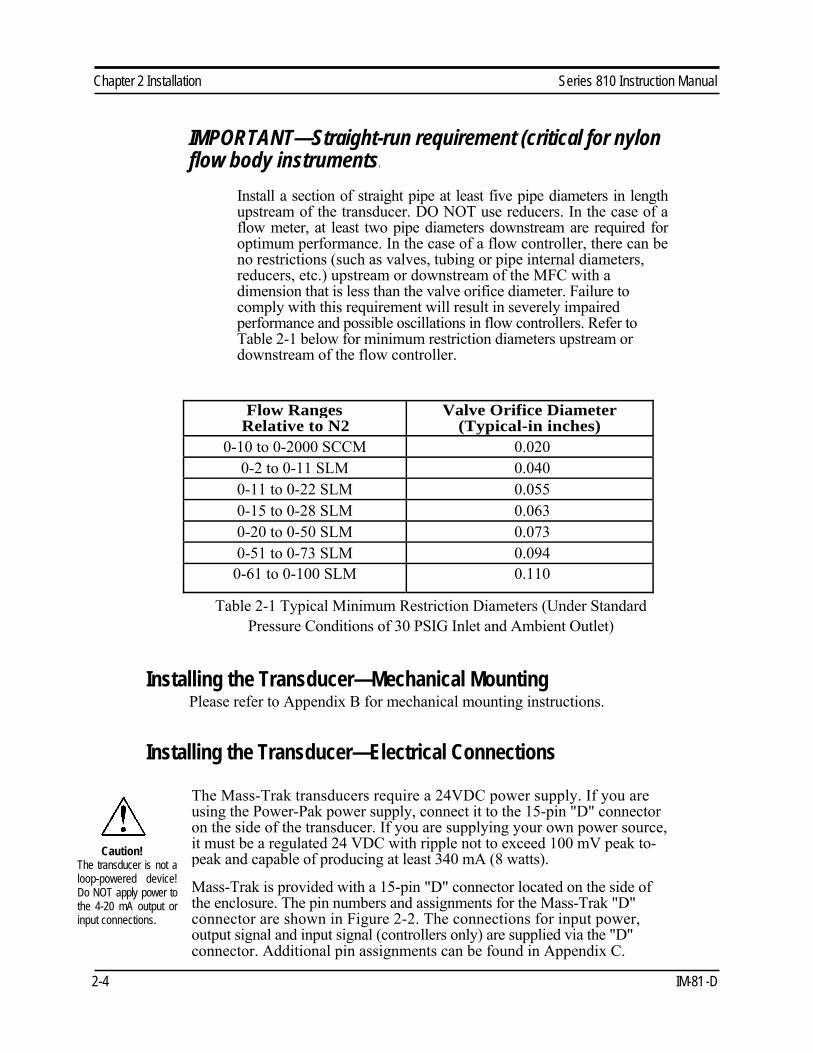
IMPORTANT—Straight-run requirement (critical for nylon
flow body instruments)
Install a section of straight pipe at least five pipe diameters in length
upstream of the transducer. DO NOT use reducers. In the case of a
flow meter, at least two pipe diameters downstream are required for
optimum performance. In the case of a flow controller, there can be
no restrictions (such as valves, tubing or pipe internal diameters,
reducers, etc.) upstream or downstream of the MFC with a
dimension that is less than the valve orifice diameter. Failure to
comply with this requirement will result in severely impaired
performance and possible oscillations in flow controllers. Refer to
Table 2-1 below for minimum restriction diameters upstream or
downstream of the flow controller.
Flow Ranges
Relative to N2
Valve Orifice Diameter
(Typical-in inches)
0-10 to 0-2000 SCCM 0.020
0-2 to 0-11 SLM 0.040
0-11 to 0-22 SLM 0.055
0-15 to 0-28 SLM 0.063
0-20 to 0-50 SLM 0.073
0-51 to 0-73 SLM 0.094
0-61 to 0-100 SLM 0.110
Table 2-1 Typical Minimum Restriction Diameters (Under Standard
Pressure Conditions of 30 PSIG Inlet and Ambient Outlet)
Installing the Transducer—Mechanical Mounting
Please refer to Appendix B for mechanical mounting instructions.
Installing the Transducer—Electrical Connections
Caution!
The transducer is not a
loop-powered device!
Do NOT apply power to
the 4-20 mA output or
input connections.
The Mass-Trak transducers require a 24VDC power supply. If you are
using the Power-Pak power supply, connect it to the 15-pin "D" connector
on the side of the transducer. If you are supplying your own power source,
it must be a regulated 24 VDC with ripple not to exceed 100 mV peak to- peak and capable of producing at least 340 mA (8 watts).
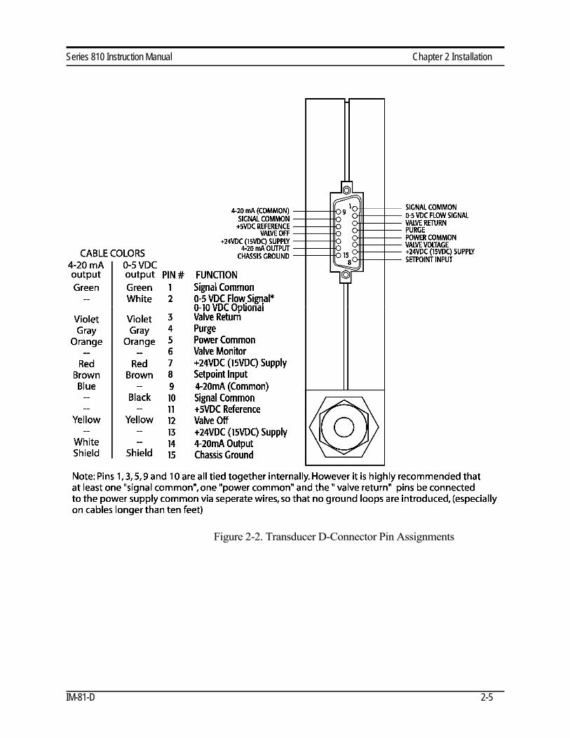
Mass-Trak is provided with a 15-pin "D" connector located on the side of
the enclosure. The pin numbers and assignments for the Mass-Trak "D"
connector are shown in Figure 2-2. The connections for input power,
output signal and input signal (controllers only) are supplied via the "D"
connector. Additional pin assignments can be found in Appendix C.
2-4 IM-81 -D
Series 810 Instruction Manual Chapter 2 Installation
Figure 2-2. Transducer D-Connector Pin Assignments
IM-81-D 2-5

Series 810 Instruction Manual Chapter 3 Operation
Chapter 3 Operation
This chapter covers transducer operation and controller features available on
Sierra's Mass-Trak' models.
Standard output for all transducers are linear 0-5 VDC (0-10 VDC optional)
and 4-20 mA output signals corresponding to 0 to 100% of the mass flow
full-scale range. For mass flow controllers, an input signal of 0-5 VDC
(0-10 VDC optional) or 4-20 mA, or use of the local set-point control,
allows users to set the gas flow rate to any desired value within the range of
the model. This input signal is a direct linear representation of 0 to 100% of
the mass flow full-scale value.
Mass Flow Meter Operation (see below for Controllers)
After the transducer is installed and the system has undergone a complete
leak check, follow these steps:
Caution!
The Mass-Trak is not a
loop-powered device. Do
not allpy power to the 4- 20 mA sections.
1. Apply power to your Mass-Trak using Sierra's power supply or your
own input power source. When power is first applied, the output signal
will remain at a high level until the sensor reaches its normal operating
temperature range. This requires approximately 20 seconds, after which
time (assuming no gas flow is present) the signal and display will drop
to 0 VDC (or 4 mA). Allow at least an additional 15 minutes of
additional warm-up time before performing any other performance
checks or adjustments.
2. Perform an initial zero output check (required for first-time start ups
only). Make certain there is no gas flowing through the instrument. If
the input pressure listed on the instrument data label is atmospheric, turn
on the meter and confirm that the display reads zero +/- 1.5% of full
scale and that the output reads zero +/-0.075V or +/-0.24mA. If the
reading exceeds these limits, you may adjust the zero potentiometer
(located on the front panel—see Figure 1-1 in Chapter 1). Turning the
potentiometer screw clockwise increases the zero. If the inlet pressure
listed on the data label is greater than atmospheric, apply gas pressure to
the instrument's inlet and block off the outlet in order to obtain the
recorded static pressure. If necessary, adjust the zero as above.
3. Open the gas supply. Mass-Trak will begin monitoring the gas mass
flow rate.
Mass Flow Controller Operation
After the transducer is installed and the system has undergone a complete
leak check, follow these steps:
1. Ensure the set point is zero before applying power. If the setpoint input
is not connected to some type of command control device, DIP switch
#1 must be in the "internal source" position or the valve-off function
must be activated (see Setpoint Adjustment and Configuration section
IM-81-D 3-1
Chapter 3 Operation Series 810 Instruction Manual
below). Note: If no setpoint command is present on a
controller when powered-up and the valve is not switched
off, the valve may drift wide open. (The valve will open
momentarily when power is first applied).
2. Apply power to your Mass-Trak using Sierra's power supply or your
own input power. When power is first applied, the output signal will
remain at a high level until the sensor reaches its normal operating
temperature range. This requires approximately 20 seconds, after which
time (assuming no gas flow is present) the signal and display will drop
to 0 VDC (or 4 mA). Allow at least 15 minutes of additional warm-up
time before performing any other performance checks or adjustments.
3. Perform an initial zero output check (required for first-time start-ups
only). Make certain there is no gas flowing through the instrument.
Confirm that the display reads zero + 1.5% of full-scale and that the
output signal is less than + 0.075 VDC or + 0.24 mA (this is maximum
allowable within the accuracy specification of the transducer). If the
reading exceeds these limits, you may adjust the zero potentiometer
(located on the front panel—see Figure 1-1 in Chapter 1). Turning the
potentiometer screw clockwise increases the zero.
4. Open the gas supply. Mass-Trak will begin monitoring the gas mass
flow rate
5. Adjust the controller set point to the desired flow rate. The effective
control range of the unit is 10% to 100% of the calibrated full scale flow
range. Below 2%, the control valve will automatically shut off the flow
unless this function is disabled (see below).
Mass Flow Controller Features
Setpoint Adjustment
The setpoint input signal is a direct linear representation of 0-100% of the
mass flow full-scale value. A 0 VDC (or 4 mA) set point will regulate the
flow to 0% and a 5.00 VDC (20 mA) set point will adjust the flow to 100%
of the instrument's calibrated range.
The setpoint signal may be applied externally or internally. If you wish to
use the internal setpoint potentiometer, it may be accessed through the front
panel. Turning the potentiometer clockwise increases the setpoint. Either
0-5 VDC (0-10 VDC optional) or 4-20 mA external setpoint commands are
available through the D-connector. See Appendix C for wiring details.
When the command (setpoint) signal is applied, the flow controller will
respond to changes in the setpoint within six seconds to ±2% of full scale of
the selected flow rate.
3-2 IM-81 -D
Series 810 Instruction Manual Chapter 3 Operation
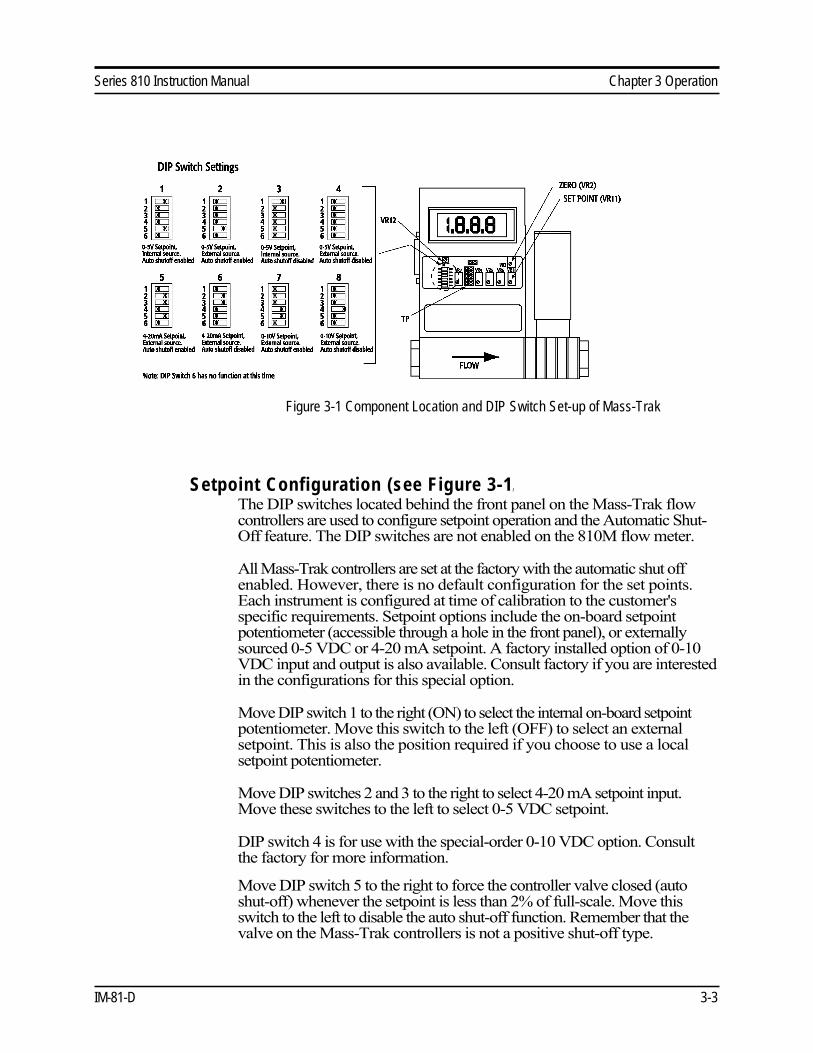
Figure 3-1 Component Location and DIP Switch Set-up of Mass-Trak
Setpoint Configuration (see Figure 3-1 )
The DIP switches located behind the front panel on the Mass-Trak flow
controllers are used to configure setpoint operation and the Automatic Shut- Off feature. The DIP switches are not enabled on the 810M flow meter.
All Mass-Trak controllers are set at the factory with the automatic shut off
enabled. However, there is no default configuration for the set points.
Each instrument is configured at time of calibration to the customer's
specific requirements. Setpoint options include the on-board setpoint
potentiometer (accessible through a hole in the front panel), or externally
sourced 0-5 VDC or 4-20 mA setpoint. A factory installed option of 0-10
VDC input and output is also available. Consult factory if you are interested
in the configurations for this special option.
Move DIP switch 1 to the right (ON) to select the internal on-board setpoint
potentiometer. Move this switch to the left (OFF) to select an external
setpoint. This is also the position required if you choose to use a local
setpoint potentiometer.
Move DIP switches 2 and 3 to the right to select 4-20 mA setpoint input.
Move these switches to the left to select 0-5 VDC setpoint.
DIP switch 4 is for use with the special-order 0-10 VDC option. Consult
the factory for more information.
Move DIP switch 5 to the right to force the controller valve closed (auto
shut-off) whenever the setpoint is less than 2% of full-scale. Move this
switch to the left to disable the auto shut-off function. Remember that the
valve on the Mass-Trak controllers is not a positive shut-off type.
IM-81-D 3-3

Chapter 3 Operation Series 810 Instruction Manual
A 5.1 VDC reference is provided for internal and external setpoint
command pots. The reference provides approximately 0.125 volts
headroom to allow for external cabling and ensures that the instrument will
always reach full scale when using these inputs.
DIP switch 6 has no function at this time.
Over-Range
If the flow rate exceeds the full-scale range listed on your Mass-Trak's data
label, the output signal and digital display will read a value above full- scale. The Mass-Trak has not been calibrated for over-ranged flows and
will be both non-linear and inaccurate if an over-range condition exists.
The 0-5 VDC (0-10 optional) and 4-20 mA outputs can exceed full scale by
as much as 50%, or more. On the digital display, the display cannot
exceed the four digits 1999. If the flow rate exceeds 1999, the right-most
digits will appear blank and only the left-hand "1" will appear on the
display.
Once the over-range condition has been removed, it may take several
minutes for the Mass-Trak to recover and resume normal operation. An
over-range condition will not harm the instrument.
Cold Sensor Lockout Circuit
Mass-Trak controllers incorporate a safety circuit that closes the valve when a fault condition is detected that could result in uncontrolled flow (valve wide open). The circuit operates by monitoring the temperature of the sensor elements and forcing the output high if the temperature falls below a preset limit. There are several conditions under which this may occur:
1. Operation at a temperature below that for which the instrument is rated.
2. Power failure while running at or near full-scale. Upon resumption of
power, the valve will remain closed until the minimum operating
temperature is reached.
3. A rapid, uncontrolled increase of gas flow through the transducer can
create a cooling effect on the sensor, driving it below the preset limit.
One possible scenario where this may occur is if backpressure
downstream from the instrument is suddenly reduced. Another scenario
is if the gas pressure should suddenly go to zero while the set point
remains at a fixed position. This could occur if a valve upstream is
closed, for example. When the pressure is re-instated, a rapid,
uncontrolled gas flow could occur activating the cold sensor lockout
circuit.
3-4 IM-81 -D
Series 810 Instruction Manual Chapter 3 Operation
4. Sensor failure.
The cold sensor lockout circuit is enabled during initial start-up. Its
operation may be checked by observing the output signal or the LCD
display (on models so equipped). The output signal or display will read
high for the first 10 to 20 seconds. After that, assuming zero flow, the
output will drop to 0 VDC or 4mA, depending on which output you are
observing. If this occurs, the circuit is working properly.
Controller Auto Shut-Off Function
All flow controllers are normally provided with an Auto Shut-Off feature
that closes the valve at a command signal level of 0.5-3% or less of full-scale.
On the Mass-Trak, this feature is factory enabled by setting DIP switch 5 to
the right to disable this feature, move DIP switch 5 to the left. The valve
will then remain open even when the setpoint falls below 2% of full-scale.
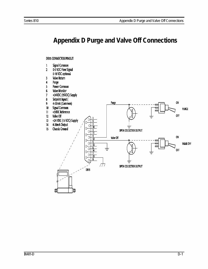
Manual Valve Override (Manual Valve On-Off Control)
Manual valve override is provided for all mass flow controllers. This
feature is available by connecting a manual on-off switch to the transducer
D-connector across pins 3 and 12 (see Appendix D). Normal operation
resumes when pin 12 is left floating.
Valve Purge Function of Mass-Trak Controllers
The purge function opens the controller valve completely for the purpose of
purging the meter and for quickly flushing unwanted gas from the flow
path. When the valve is opened for purging, it allows flows far in excess
of the rated full scale of the controller. Because of the uncontrolled nature
of the purge function, two conditions must be met before a controller can
be purged:
The Manual Valve Override, if it is being used, must be in the ON or open
state.
The Auto-Shutoff function cannot be active (the setpoint command signal
must be above 2% of full scale or DIP switch 5 must be in the OFF
position).
The activation of either the Manual Valve Override or the Auto-Shutoff
function will override the purge command.
To activate purge, connect pin 4 of the 15-pin "D" connector to common
through either a mechanical switch or an open-collector transistor or logic
output capable of sinking at least 4mA (See Appendix D). The maximum
voltage appearing on this pin is 5.0 VDC.
IM-81-D 3-5
Chapter 3 Operation Series 810 Instruction Manual
Purging Non-Reactive Gases:
Purge the transducer with clean, dry nitrogen for a minimum of two
hours.
Caution!
Always fully
neutralize any toxic
gas trapped inside
the transducer
before removing it
Purging Reactive Gases:
One of the following methods may be used:
• Cycle purge. This is done by alternately evacuating and purging the transducer for 2 to 4 hours with clean, dry nitrogen.
• Purge the transducer with clean, dry nitrogen for 8 to 24 hours.
• Evacuate the transducer for 8 to 24 hours.
When toxic or corrosive gases are used, purge unit thoroughly with inert
dry gas before disconnecting from the gas line. If a transducer used with a
toxic or corrosive gas is returned to the factory, a Material Safety Data Sheet
must be enclosed with the unit upon its return.
3-6 IM-81 -D

Series 810 Instruction Manual Chapter 4 Maintenance
Caution)
Always fully neutralize
any toxic gas trapped
inside the transducer
before removing from
the gas line.
Chapter 4 Maintenance
Mass-Trak- transducers require very little scheduled maintenance. In the
event that minor maintenance or adjustment is required, this chapter
provides general instructions for:
• Flow Path Maintenance and Cleaning
• Sensor Maintenance and Cleaning
• Valve Maintenance and Adjustment
• Transducer Calibration
Flow Path Maintenance
The transducer flow path should be periodically inspected and cleaned as
required. If an in-line filter is used, the filtering element should be
replaced periodically or ultrasonically cleaned.
The flow path is made of 316 stainless steel or glass-filled nylon (wetted
magnetic parts of the solenoid valve are 430F stainless steel) with Viton®,
Neoprene , or Kalrez® (or equivalent) seals, depending on the gas used.
If toxic or corrosive gases are used, purge unit thoroughly with inert dry
gas before disconnecting it from the gas line. If a transducer used with a
toxic or corrosive gas is returned to the factory, a Material Safety Data Sheet
must be enclosed with the unit upon its return.
Cleaning the Mass-Trak
Caution)
Do not disassemble the
instrument without
contacting the Sierra
Instruments customer
service department.
After purging (see Chapter 3), carefully remove the transducer from the gas
line. You may find a fine-mesh filter screen inside the inlet of the
instrument. Inspect the inlet fitting and the filter screen, if there is one, and
blow away any particles resting in or adhering to this area with low- pressure compressed air. If the screen appears corroded or damaged it will
need to be replaced. Contact the Sierra Instruments Customer Service
Department before removing the fittings or the screen, as it is possible to
shift calibr a tion of the instrument at this point. If calibration shifts, you will
have to return your instrument to an authorized repair center for re- calibration.
IM-81-D 4-1
Chapter 4 Maintenance Series 810 Instruction Manual
Caution!
Do not remove the sensor
cover, this could shift
transducer calibration.
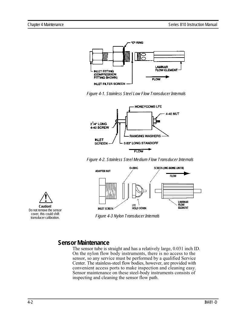
Figure 4-1. Stainless Steel Low Flow Transducer Internals
Figure 4-2. Stainless Steel Medium Flow Transducer Internals
Figure 4-3 Nylon Transducer Internals
Sensor Maintenance
The sensor tube is straight and has a relatively large, 0.031 inch ID.
On the nylon flow body instruments, there is no access to the
sensor, so any service must be performed by a qualified Service
Center. The stainless-steel flow bodies, however, are provided with
convenient access ports to make inspection and cleaning easy.
Sensor maintenance on these steel-body instruments consists of
inspecting and cleaning the sensor flow path.
4-2 IM-81 -D
Series 810 Instruction Manual Chapter 4 Maintenance
Caution!
When using toxic or
corrosive gases, purge the
unit with inert dry gas
before disconnecting from
the gas line.
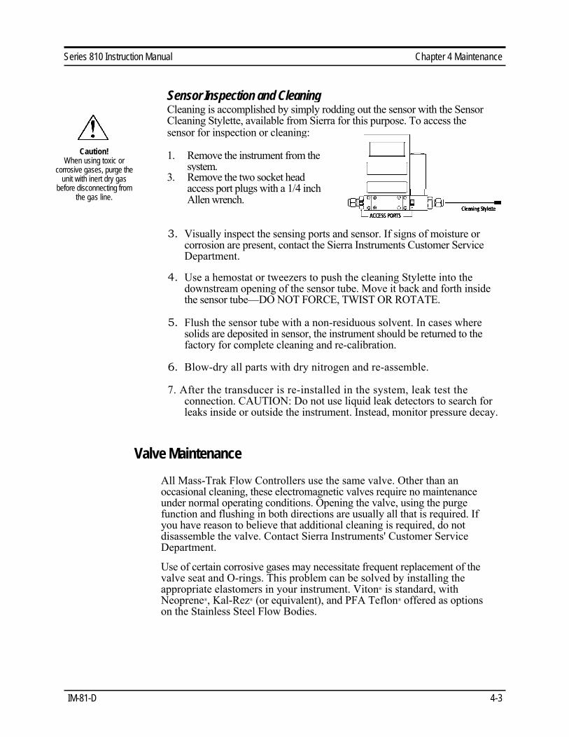
Sensor Inspection and CleaningCleaning is accomplished by simply rodding out the sensor with the Sensor
Cleaning Stylette, available from Sierra for this purpose. To access the
sensor for inspection or cleaning:
1. Remove the instrument from the
system. 3. Remove the two socket head
access port plugs with a 1/4 inch
Allen wrench.
3. Visually inspect the sensing ports and sensor. If signs of moisture or
corrosion are present, contact the Sierra Instruments Customer Service
Department.
4. Use a hemostat or tweezers to push the cleaning Stylette into the
downstream opening of the sensor tube. Move it back and forth inside
the sensor tube—DO NOT FORCE, TWIST OR ROTATE.
5. Flush the sensor tube with a non-residuous solvent. In cases where
solids are deposited in sensor, the instrument should be returned to the
factory for complete cleaning and re-calibration.
6. Blow-dry all parts with dry nitrogen and re-assemble.
7. After the transducer is re-installed in the system, leak test the
connection. CAUTION: Do not use liquid leak detectors to search for
leaks inside or outside the instrument. Instead, monitor pressure decay.
Valve Maintenance
All Mass-Trak Flow Controllers use the same valve. Other than an
occasional cleaning, these electromagnetic valves require no maintenance
under normal operating conditions. Opening the valve, using the purge
function and flushing in both directions are usually all that is required. If
you have reason to believe that additional cleaning is required, do not
disassemble the valve. Contact Sierra Instruments' Customer Service
Department.
Use of certain corrosive gases may necessitate frequent replacement of the
valve seat and O-rings. This problem can be solved by installing the
appropriate elastomers in your instrument. Viton® is standard, with
Neoprene®, Kal-Rez® (or equivalent), and PFA Teflon® offered as options
on the Stainless Steel Flow Bodies.
IM-81-D 4-3
Chapter 4 Maintenance Series 810 Instruction Manual
Valve Adjustment
Mass-Trak controls flow with a proportional electromagnetic valve
that is set up for certain process operation conditions. Variables that
affect its operation include orifice size, spring selection and
adjustment, and input and output pressures. If operating conditions
change it may be necessary to make a valve spring adjustment. An
adjustment may also be required due to dimpling of the valve seat or
spring sag, both of which can cause a change in the internal
dimensions of the valve. Please note that performing the following
procedure will NOT affect your transducer's calibration and MUST
be performed with the instrument installed at normal operating
conditions.
An incorrectly adjusted valve can be detected by one of the
following symptoms:
• Leakage at a zero set point
• The instrument will not reach maximum flow
• The output is unstable
• Valve oscillation
The following valve adjustment procedure can be followed to correct
the above conditions. You will need:
• 1/16" hex wrench
• 5/16" nut driver or socket
All controllers should be thoroughly leak-tested following any valve
adjustment. CAUTION: Do not use liquid leak detectors to search
for leaks inside or outside the instrument. Instead, monitor pressure
decay.
Procedure:
If the instrument is experiencing leak-by with a zero setpoint,
remove the plastic cover from the top of the solenoid valve, located to the right of the electronics enclosure. Apply inlet and outlet pressures to the controller as recorded on either the data label or Calibration Certificate of your instrument. Loosen the 5/16" lock nut (not the large, white, plastic nut, but the smaller one on top of it.) Adjust the center adjustment screw (using a 1/16" hex wrench) slowly, clockwise, 1/8 turn at a time. This increases the spring tension in the valve. Continue until the leak-by subsides. Next, adjust this screw clockwise one half-turn past this point, tighten the locknut and replace the cap. Test the controller operation at various setpoints over its operational range.
4-4 IM-81 -D

Series 810 Instruction Manual Chapter 4 Maintenance
If your unit is experiencing one of the other symptoms listed above,
remove the small front access door to expose the test points, pots
and DIP switches. (see figure 3.1)
TESTPOINT BLOCK (labeled TP in Figure 3.1):
Setpoint TP10 * * TP9 Valve +
+5V Reference TP8 * * TP7 4-20mA out
0-5 volt out TP6 * * TP5 Common
Bias Voltage TP4 * * TP3 Test Flow Signal
Sensor Amp TP2 * * TP1 Bridge Voltage
Caution!
It is important that
only qualified
personnel calibrated
this transducer.
1. Connect a voltmeter to test points 9 (Valve +) and 5 (Common) and set
the scale for 30 volts or higher.
2. Apply two set points, one at 5% full scale and then one at 100% full
scale — either locally or remotely (be sure the dip switches are in the
proper positions). Monitor the valve voltage at each point. The
acceptable range for the valve voltage is 6 to 18 VDC over these two set
points.
3. If the valve voltage is outside of these specifications, loosen the 5/16"
lock nut, and adjust the center adjustment screw. Turning clockwise
will increase the valve voltage, while turning counterclockwise will
decrease it. Adjust slowly, 1/8 turn at a time while monitoring valve
performance. When the desired voltage is obtained, the symptoms
should disappear and the lock nut can be re-tightened.
4. Re-install the front access door and conduct a final check for leak-by
with a zero set point, paying particular attention to the seal on the
adjusting screw. Remember to monitor pressure decay only, as liquid
leak detectors may damage the instrument.
If these adjustments do not restore proper performance to your Mass-Trak,
contact Sierra Instruments' Technical Support Department.
Transducer Calibration
Calibration of Sierra's flow meters and controllers requires a calibration
standard of at least equal accuracy and preferably an order of magnitude
IM-81-D 4-5

Chapter 4 Maintenance Series 810 Instruction Manual
better than the transducer, and a skilled technician familiar with the Mass-Trak transducer. It is recommended that Mass Trak meters and controllers
be returned to the factory for annual calibration.
Sierra Instruments maintains two fully equipped calibration facilities:
one at the USA headquarters and the other at the European
headquarters. All measuring and test equipment used in the
calibration of Sierra transducers is traceable to NIST standards.
Sierra is ISO-9001 registered and conforms to the requirements of
ANSI/NCSL-Z540 and ISO/IEC Guide 25. If your instrument has
been damaged or you simply want to have the transducer re- calibrated, see Chapter 5 or contact the factory for return shipping
instructions.
4-6 IM-81 -D
Series 810 Instruction Manual Chapter 5 Troubleshooting and Service
Chapter 5 Transducer Troubleshooting
When you suspect that the transducer is not operating correctly, there are a
few simple checks that can be made before taking the unit out of service:
1. Make certain that there are no leaks in the gas line.
2. Check that all cables are connected and are in good condition.
3. Verify that the power supply is in the correct range and properly
connected to the transducer.
4. Double check connector pin-outs if replacing another manufacturer's
transducer.
5. Verify that the DIP switches are configured correctly for your
application.
6. Verify that there is adequate inlet gas pressure to the transducer, that
there are no downstream restrictions and that any upstream valves are
open to allow sufficient gas flow to reach the instrument.
The following information is provided to help locate the cause of a
transducer failure. It is not intended to be an all inclusive repair guide. For
most repairs, the unit should be returned to the factory for service.
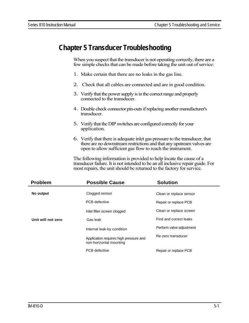
Problem Possible Cause Solution
No output Clogged sensor
PCB defective
Inlet filter screen clogged
Unit will not zero Gas leak
Internal leak-by condition
Application requires high pressure and
non-horizontal mounting
PCB defective
Clean or replace sensor
Repair or replace PCB
Clean or replace screen
Find and correct leaks
Perform valve adjustment
Re-zero transducer
Repair or replace PCB
IM-810-D 5-1

Chapter 5 Troubleshooting and Service Series 810 Instruction Manual
Controller does not Low or no gas pressure
respond to set point
Faulty cable or connector
Set point is below 2% of full scale
DIP switches improperly set
Flow does not match set
point
Reads full scale with no
flow or with valve shut
No gas pressure (or low pressure)
Inlet filter screen clogged
Out of adjustment
Gas Leak
Defective Sensor
Out of calibration Dirty or clogged sensor
Change in composition of gas
Gas leak
PCB defective
LFE dirty
Inlet filter screen clogged
Reference conditions incorrect
Set correct gas pressure
Correct or replace
Increase set point or disable auto
shut off circuit
Re-configure DIP switches
Set correct gas pressure
Clean or replace
Consult factory
Find and correct leaks
Return to factory for replacement
Clean or replace sensor
See K-factor tables
Find and correct leaks
Repair or replace PCB
Consult factory
Clean or replace screen
Check reference conditions on data
label and correct as required.
5-2 IM-81 -D
Series 810 Instruction Manual Chapter 5 Troubleshooting and Service
Returning Equipment to the Factory
Before returning any transducer to the factory, you must request and
complete a Sierra Calibration/Repair Data Sheet. To obtain the data
sheet contact Customer Service at:
USA Headquarters
Sierra Instruments
Service Department
5 Harris Court, Building W
Monterey, CA 93940
Ph. (800) 866-0200 or (831) 373-0200
Fx. (831) 373-2414
European Headquarters
Sierra Instruments b.v.
Service Department
Bijlmansweid 2
1934RE Egmond a/d Hoef
The Netherlands
Ph. +31 72 5071400
Fx. +31 72 5071401
When returning a component, make sure to include the completed
Calibration/Repair Data Sheet and send the item to the appropriate address
above. If an instrument used with any toxic or corrosive gas is returned to
the factory, a Material Safety Data Sheet must accompany the instrument.
IM-810-D 5-3
Series 810 Instruction Manual Appendix A
Appendix A Conversion Formulas and Gas Tables
Calculations For Use with a Pure Gas
The following tables provide K-factors and thermodynamic properties of
gases commonly used with mass flow meters and controllers. The purpose
of these tables is two-fold:
1. Calibrating an “actual” gas with a reference gas. This is particularly
useful if the actual gas is not a common gas or if it is toxic, flammable,
corrosive, etc.
2. Interpreting the reading of a flow meter or flow controller that has been
calibrated with a gas other than the actual gas.
In applying the tables, the following fundamental relationship is used:
Q1/Q2 = K1/K2 (1)
Where:
Q = The volumetric flow rate of the gas referenced to standard
conditions of 0°C and 760 mm Hg (sccm or slm),
K = The K-factor defined in equation (6),
( ) 1 = Refers to the “actual” gas, and
( ) 2 = Refers to the “reference” gas.
The K-factor is derived from the first law of thermodynamics applied to the
sensor tube, as described in Chapter 1:
H = m N OT ( 2 )
Where:
H = The constant amount of heat applied to the sensor tube,
m = The mass flow rate of the gas (gm/min)
Cñ = The coefficient of specific heat of the gas (Cal/gm); Cñ is given in the Table (at 0°C),
∆T = The temperature difference between the downstream and
upstream coils, and
N = A correction factor for the molecular structure of the gas
given by the following table:
IM-81-D A-1
Appendix A Series 810 Instruction Manual
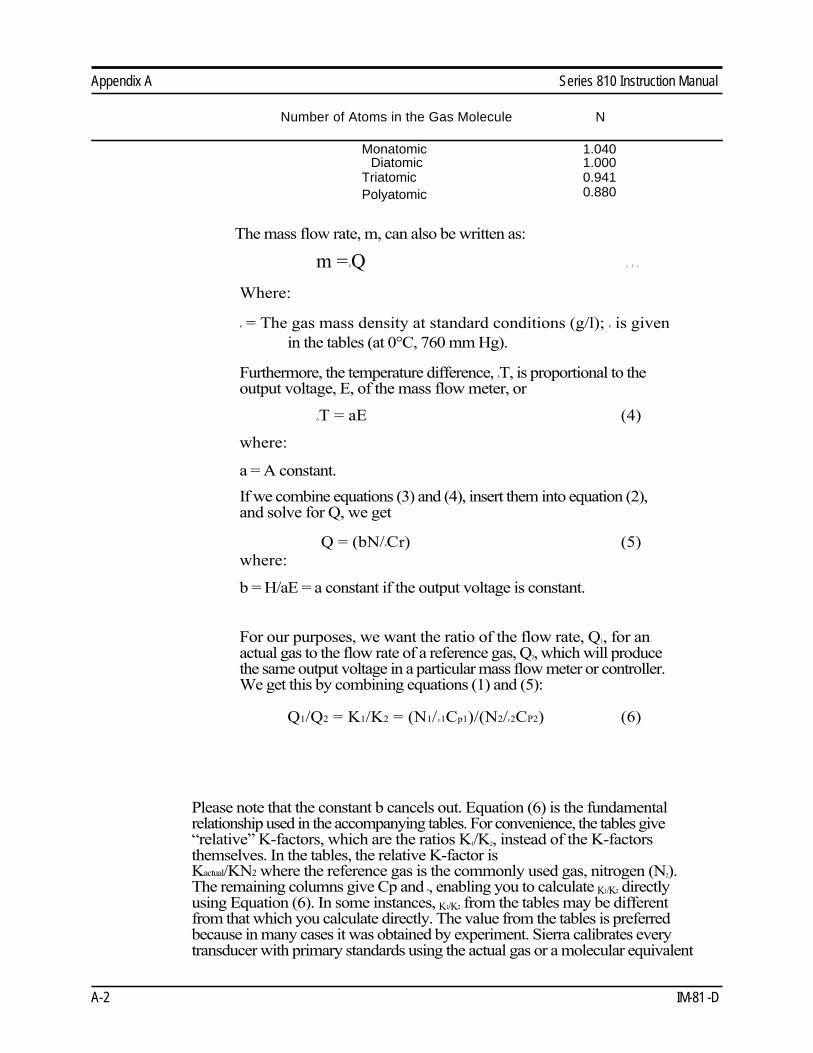
Number of Atoms in the Gas Molecule N
Monatomic 1.040
Diatomic 1.000
Triatomic 0.941
Polyatomic 0.880
The mass flow rate, m, can also be written as:
m = PQ ( 3 )
Where:
P = The gas mass density at standard conditions (g/l); P is given
in the tables (at 0°C, 760 mm Hg).
Furthermore, the temperature difference, AT, is proportional to the
output voltage, E, of the mass flow meter, or
AT = aE (4)
where:
a = A constant.
If we combine equations (3) and (4), insert them into equation (2),
and solve for Q, we get
Q = (bN/PCr) (5)
where:
b = H/aE = a constant if the output voltage is constant.
For our purposes, we want the ratio of the flow rate, Q1, for an
actual gas to the flow rate of a reference gas, Q2, which will produce
the same output voltage in a particular mass flow meter or controller.
We get this by combining equations (1) and (5):
Q1/Q2 = K1/K2 = (N1/ P1Cp1)/(N2/P2CP2) (6)
Please note that the constant b cancels out. Equation (6) is the fundamental
relationship used in the accompanying tables. For convenience, the tables give
“relative” K-factors, which are the ratios K1/K2, instead of the K-factors
themselves. In the tables, the relative K-factor is
Kactual/KN2 where the reference gas is the commonly used gas, nitrogen (N2).
The remaining columns give Cp and P, enabling you to calculate K1/K2 directly
using Equation (6). In some instances, K1/K2 from the tables may be different
from that which you calculate directly. The value from the tables is preferred
because in many cases it was obtained by experiment. Sierra calibrates every
transducer with primary standards using the actual gas or a molecular equivalent
A-2 IM-81 -D
Series 810 Instruction Manual Appendix A
reference gas. The calibration certificate accompanying the transducer cites the
reference gas used.
Example 1:
A transducer is calibrated for nitrogen (N2), and the flow rate is 1000 sccm
for a 5.000 VDC output signal. The flow rate for carbon dioxide at a 5.000
VDC output is:
QCO2/QN2 = KCO2/K N2, or
QCO2 = (0.74/1.000)1000 = 740 sccm
Example 2:
A transducer is calibrated for hydrogen (H2), and the flow rate is 100 sccm
for a 5.000 VDC output signal. The flow rate for nitrous oxide (N2O) is
found as follows:
QN2O/QH2 = K N2O/K H2, or
Q N2O = (0.71/1.01) 100 = 70.3 sccm
Note that the K -factors relative to nitrogen must be used in each case.
Calculating Dual Gas Mixtures
Equation (6) is used for gas mixtures, but we must calculate N/ñCp for the
mixture. The equivalent values of ñ, Cp, and N for a dual
gas mixture are given as follows:
The equivalent gas density is:
ρ = ( m 1 m / T P 1 ) 4 l T P 2 / )
Where: • • mT = m 1+ 1112 = Total mass flow rate (gm/min),
( )1 = Refers to gas #1, and
( )2 = Refers to gas #2
The equivalent specific heat is:
Cp = F1Cp1 + F2Cp2
Where:
F1 = (1111 P1 )/(l"T P) and
F2= (m2 )/ (" 'T ρ)
The equivalent value of N is: L
Ν = j 1 m ~ 1 ) Ν m 2 + T 4 2 / ) Ν
IM-81-D A-3
Appendix A Series 810 Instruction Manual
The equivalency relationships for p, Cp, and N for mixtures of
more than two gases have a form similar to the dual-gas
relationship given above.
IMPORTANT NOTE ABOUT K-FACTORS:
Please note that if you have a transducer calibrated for a gas such as
methane and wish to use the K-factors to measure a gas such as air,
the inaccuracy of the measurement can range from ±5 to 10%. The
use of K-factors is, at best, only a rough approximation and should
not be used in applications that require a better than ±5 to 10%
accuracy.
It should also be noted that certain gases, in similar “families,”
would work exceptionally well with K-factors; however, those
instances are only true when similar thermal properties of the gas are
present.
A-4 IM-81 -D

Series 810 Instruction Manual Appendix A
Gas Tables and K-factors
Actual Gas
Chemical
Symbol
K-factor
Relative
N2
Cp
(Cal/g)
Density
(g/l) @
0°C
Elastomer* O-ring Valve
Seat
Nylon
Compatible
Acetylene
C2H2 .58 .4036 1.162 Air 1.00 .240 1.293
Allene (Propadiene) C3H4 .43 .352 1.787 KR
Ammonia NH3 .73 .492 .760 NEO NEOArgon Ar 1.45 .1244 1.782
Arsine AsH3 .67 .1167 3.478 KR
Boron Trichloride BCL3 .41 .1279 5.227 KR KR
Boron Trifluoride BF3 .51 .1778 3.025 KR
Boron Tribromide Br3 .38 .0647 11.18 KR
Bromine Br2 .81 .0539 7.130 NO
Bromine Pentafluoride BrF5 .26 .1369 7.803 KR NO
Bromine Trifluoride BrF3 .38 .1161 6.108 KR NO
Bromotrifloromethane CBrF3 .37 .1113 6.644
(Freon-13 B1)
1,3-Butadiene C4H6 .32 .3514 2.413
Butane C4H10 .26 .4007 2.593 NEO KR
1-Butane C4H8 .30 .3648 2.503 NEO KR
2-Butane C4H8 CIS .324 .336 2.503 NEO KR
2-Butane C4H8 TRANS .291 .374 2.503
Carbon Dioxide CO2 .74 .2016 1.964
Carbon Disulfide CS2 .60 .1428 3.397
Carbon Monoxide CO 1.00 .2488 1.250Carbon Tetrachloride CCL4 .31 .1655 6.860 KR NO
Carbon Tetrafluoride CF4 .42 .1654 3.926 KR
(Freon-14)
Carbonyl Fluoride COF2 .54 .1710 2.945
Carbonyl Sulfide COS .66 .1651 2.680
Chlorine CL2 .86 .1144 3.163 KR NO
Chlorine Trifluoride CLF3 .40 .1650 4.125 KR
Chlorodifluoromethane CHCLF2 .46 .1544 3.858 KR
(Freon-22)
Chloroform CHCL3 .39 .1309 5.326 KR
Ch loropentafl uoroethane C2CLF5 .24 .164 6.892 KR
(Freon-115)
Chlorotrifluromethane CCLF3 .38 .153 4.660 KR
(Freon-13)
Cyanogen C2N2 .61 .2613 2.322 KR
Cyanogen Chloride CLCN .61 .1739 2.742
Cychlopropane C3H5 .46 .3177 1.877 KR
Deuterium D2 1.00 .1722 1.799
Diborane B2H6 .44 .508 1.235 KR
Dibromodifluoromethane CBr2F2 .19 .15 9.362 KR
Dibromethane .47 .075 7.76 KR
Dichlorodifluoromethane CCL2F2 .35 .1432 5.395 KR
(Freon-12)
Dichlorofluoromethane CHCL2F .42 .140 4.592 KR
(Freon-21) * If no O-ring material is specified then O-ring to be used is Viton. Nylon Flow Body instruments are only
available with Viton elastomers. Valve Seat applies only to controllers.
IM-81-D A-5

Appendix A Series 810 Instruction Manual
Dichloromethylsilane
Dichlorosilane
Actual Gas
DimethylamineDimethyl Ether 2,2-Dimethylpropane
Ethane
E tha nol EthylAcetylene
Ethyl Chloride
Ethylene
Ethylene Oxide
F luorine
Fluoroform (Freon-23)
Freon-11
Freon-12
Freon-13
Freon-13 B1 F reon-14
Freon-21
Freon-22
Freon-113
Freon-114
Freon-115
Freon-C318
Germane
Germanium Tetrachloride
Helium
Hexane
Hydrogen
Hydrogen Bromide
Hydrogen Chloride
Hydrogen Cyanide
Hydrogen Fluoride
Hydrogen Iodide
Isobutane
Isobutylene
K pton
Methane
Methanol
Methyl Acetylene
Methyl BromideMethyl ChlorideMethyl Fluoride
(Freon-114)
1,1-Di uoroethylene
(Freon-1132A)
(Freon-116)
Hydrogen Selenide
e
e
ry
e
Chemical Symbol
K-factor
Relative
N2
Cp
(Cal/g)
Density
(g/l) @
0°C
Elastomer* O-ring Valve
Seat
Nylon
Compatible
(CH3) 2SiCL2 .25 .1882 5.758 KR SiH 2CL 2 .40 .150 4.506 KR
C2CL2F4 .22 .1604 7.626 KR C2H2F2 .43 .224 2.857 KR
(CH 3) 2NH .37 .366 2.011 KR (CH 3) 2O .39 .3414 2.055 KR
C 3H12 .22 .3914 3.219 KR
C2H6 .50 .4097 1.342 NO
C2H6O .39 .3395 2.055 KR
C 4H6 .32 .3513 2.413 KR
C 2H5CL .39 .244 2.879 KR
C2H4 .60 ~.358 1.251
C 2H4O .52 .268 1.965 KR
F2 .980 .1873 1.695 KR
CHF 3 .50 .176 3.127 KR NO
CCL 3F .33 .1357 6.129 KR NO
CCL 2F2 .35 .1432 5.395 KR NO
CCLF 3 .38 .153 4.660 KR NO
CFrF 3 .37 .1113 6.644 KR NO
C F4 .42 .1654 3.926 N O
CHCL 2F .42 .140 4.952 KR NO
CHCLF 2 .46 .1544 3.858 KR NO
CCI2FCCLF2 .20 .161 8.360 KR NO
C 2CL 2F4 .22 .160 7.626 KR NO
C 2CLF 5 .24 .164 6.892 KR NO
C 4F6 .17 .185 8.397 KR NO
GeH4 .57 .1404 3.418
GeCL 4 .27 .1071 9.565 KR
He 1.454 1.241 .1786
C2F6 .24 .1834 6.157 KR NO
C6H14 .18 .3968 3.845 KR H2 1.01 3.419 .0899
HBr 1.000 .0861 3.610 KR
HCL 1.000 .1912 1.627 K KR
HCN .76 .3171 1.206 KR
HF 1.000 .3479 .893 KR KR
HI 1.000 .0545 5.707 KR
H 2Se .79 .1025 3.613 KR
H 2S .80 .2397 1.520 KR KR
IF 5 .25 .1108 9.90 KR
CH(CH 3)3 .27 .3872 2.593 KR
C 4H6 .29 .3701 2.503 KR
Kr 1.453 .059 3 3.739
C H4 .72 .5328 .715
CH 3OH .58 .3274 1.429
C 3H4 .43 .3547 1.787 KR
CH 3Br .58 .1106 4.236
CH 3CL .63 .1926 2.253 KR
CH 3F .68 .3221 1.518 KR * If no O-ring material is specified then O-ring to be used is Viton. . Nylon Flow Body instruments are only
available with Viton elastomers.
A-6 IM-81 -D

Series 810 Instruction Manual Appendix A
Actual Gas
Chemical Symbol
K-factor
Relative
N2
Cp
(Cal/g)
Density
(g/l) @
0°C
Elastomer* O-ring Valve
Seat
Nylon
Compatible
Methyl Mercaptan
CH3SH .52 .2459 2.146 KR Methyl Trichlorosilane (CH 3) SiCl 3 .25 .164 6.669 KR
Molybdenum Hexafluoride MoF6 .21 .1373 9.366 KR
Monoethylamine C2H5NH2 .35 .387 2.011 KR
Monomethylamine CH3NH2 .51 .4343 1.386 KR
Neon NE 1.46 .245 .900
Nitric Oxide NO .990 .2328 1.339 NO
Nitrogen N2 1.000 .2485 1.25
Nitrogen Dioxide NO2 .74 .1933 2.052 KR KR NO
Nitrogen Trifluoride NF3 .48 .1797 3.168 KR
Nitrosyl Chloride NOCl .61 .1632 2.920 KR
Nitrous Oxide N2O .71 .2088 1.964
Octafluorocyclobutane C4F6 .17 .185 8.397 KR
(Freon-C318)
Oxygen O2 1.000 .2193 1.427
Oxygen Difluoride OF2 .63 .1917 2.406
Ozone O3 .446 .3 2.144 NO
Pentaborane B5H9 .26 .38 2.816 KR
Pentane C5HL2 .21 .398 3.219 KR
Perchloryl Fluoride CLO 3F .39 .1514 4.571 KR
Perfluoropropane C3F8 .174 .197 8.388 KR
Phosgene COCL 2 .44 .1394 4.418 KR
Phosphine Ph 3 .76 .2374 1.517 KR
Phosphorous Oxychloride POCL 3 .36 .1324 6.843 KR
Phosphorous Ph 5 .30 .1610 5.620 KR
Pentafluoride
Phosphorous Trichloride PCL 5 .30 .1250 6.127 KR
Propane C3H8 .36 .3885 1.967
Propylene C3H6 .41 .3541 1.877
Silane SiH 4 .60 .3189 1.433 KR
Silicon Tetrachloride SiCL 4 .28 .1270 7.580 KR
Silicon Tetrafluoride SiF 4 .35 .1691 4.643 KR
Sulfur Dioxide So2 .69 .1488 2.858 KR
Sulfur Hexafluoride SF 6 .26 .1592 6.516 KR
Sulfuryl Fluoride SO 2F2 .39 .1543 4.562 KR
Teos .090 KR KR
Tetrafluorahydrazine N2F4 .32 .182 4.64 KR
Trichlorofluormethane CCL 3F .33 .1357 6.129 KR
(Freon-11)
Trichlorisilane SiHCL 3 .33 .1380 6.043 KR
1,1,2-Trichloro-1,2,2 CCL2FCCLF2 .20 .161 8.360 KR
Trifluorethane (Freon-113)
Trisobutyl Aluminum (C4H9)AL .061 .508 8.848 KR
Titanium Tetrachloride TiCL 4 .27 .120 8.465 KR
Trichloro Ethylene C2HCL 3 .32 .163 5.95 KR
Trimethylamine (CH 3)3N .28 .3710 2.639 KR
Tungsten Hexasfuoride WF6 .25 .0810 13.28 KR Teflon
Uranium Hexafluoride UF6 .20 .0888 15.70 KR
Vinyl Bromide CH2CHBr .46 .1241 4.772 KR
Vinyl Chloride CH2CHCL .48 .2054 2.788 KR
Xenon Xe 1.44 .0378 5.858
* If no O-ring material is specified then O-ring to be used is Viton. Nylon Flow Body instruments are only
available with Viton elastomers.
IM-81-D A-7
Series 810 Instruction Manual Appendix B Specifications & Mounting Instructions
Appendix B Product Specifications
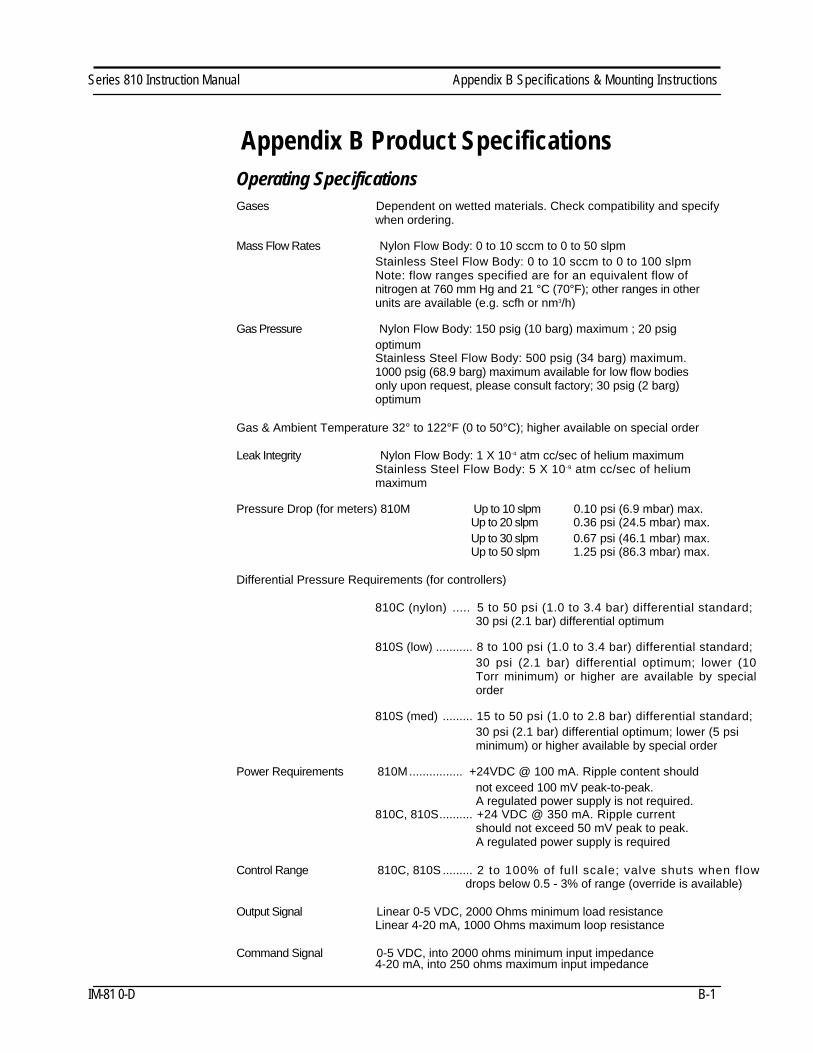
Operating Specifications
Gases Dependent on wetted materials. Check compatibility and specifywhen ordering.
Mass Flow Rates Nylon Flow Body: 0 to 10 sccm to 0 to 50 slpm Stainless Steel Flow Body: 0 to 10 sccm to 0 to 100 slpm Note: flow ranges specified are for an equivalent flow of nitrogen at 760 mm Hg and 21 °C (70°F); other ranges in other units are available (e.g. scfh or nm3/h)
Gas Pressure Nylon Flow Body: 150 psig (10 barg) maximum ; 20 psig optimum Stainless Steel Flow Body: 500 psig (34 barg) maximum. 1000 psig (68.9 barg) maximum available for low flow bodies only upon request, please consult factory; 30 psig (2 barg) optimum
Gas & Ambient Temperature 32° to 122°F (0 to 50°C); higher available on special order
Leak Integrity Nylon Flow Body: 1 X 10⁻⁴ atm cc/sec of helium maximum Stainless Steel Flow Body: 5 X 10⁻⁹ atm cc/sec of helium maximum
Pressure Drop (for meters) 810M Up to 10 slpm 0.10 psi (6.9 mbar) max. Up to 20 slpm 0.36 psi (24.5 mbar) max. Up to 30 slpm 0.67 psi (46.1 mbar) max. Up to 50 slpm 1.25 psi (86.3 mbar) max.
Differential Pressure Requirements (for controllers)
810C (nylon) ..... 5 to 50 psi (1.0 to 3.4 bar) differential standard; 30 psi (2.1 bar) differential optimum
810S (low) ........... 8 to 100 psi (1.0 to 3.4 bar) differential standard; 30 psi (2.1 bar) differential optimum; lower (10 Torr minimum) or higher are available by special order
810S (med) ......... 15 to 50 psi (1.0 to 2.8 bar) differential standard; 30 psi (2.1 bar) differential optimum; lower (5 psi minimum) or higher available by special order
Power Requirements 810M ................ +24VDC @ 100 mA. Ripple content should not exceed 100 mV peak-to-peak. A regulated power supply is not required.
810C, 810S .......... +24 VDC @ 350 mA. Ripple current should not exceed 50 mV peak to peak. A regulated power supply is required
Control Range 810C, 810S ......... 2 to 100% of full scale; valve shuts when flowdrops below 0.5 - 3% of range (override is available)
Output Signal Linear 0-5 VDC, 2000 Ohms minimum load resistance Linear 4-20 mA, 1000 Ohms maximum loop resistance
Command Signal 0-5 VDC, into 2000 ohms minimum input impedance 4-20 mA, into 250 ohms maximum input impedance
IM-81 0-D B-1
Appendix B Specifications & Mounting Instructions Series 810 Instruction Manual
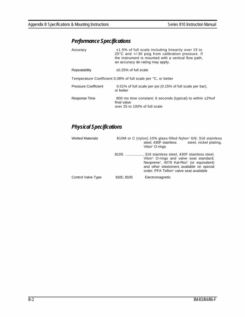
Performance Specifications
Accuracy ±1.5% of full scale including linearity over 15 to
25°C and +/-30 psig from calibration pressure. If
the instrument is mounted with a vertical flow path,
an accuracy de-rating may apply.
Repeatability ±0.25% of full scale
Temperature Coefficient 0.08% of full scale per °C, or better
Pressure Coefficient 0.01% of full scale per psi (0.15% of full scale per bar),
or better
Response Time 800 ms time constant; 6 seconds (typical) to within ±2%of
final value
over 25 to 100% of full scale
Physical Specifications
Wetted Materials 810M or C (nylon) 10% glass-filled Nylon® 6/6; 316 stainless
steel, 430F stainless steel, nickel plating,Viton® O-rings
810S ................... 316 stainless steel, 430F stainless steel,
Viton® O-rings and valve seat standard;
Neoprene®, 4079 Kal-Rez® (or equivalent)
and other elastomers available on special
order; PFA Teflon® valve seat available
Control Valve Type 810C, 810S Electromagnetic
B-2 IM-83/84/86-F
Series 810 Instruction Manual Appendix B Specifications & Mounting Instructions
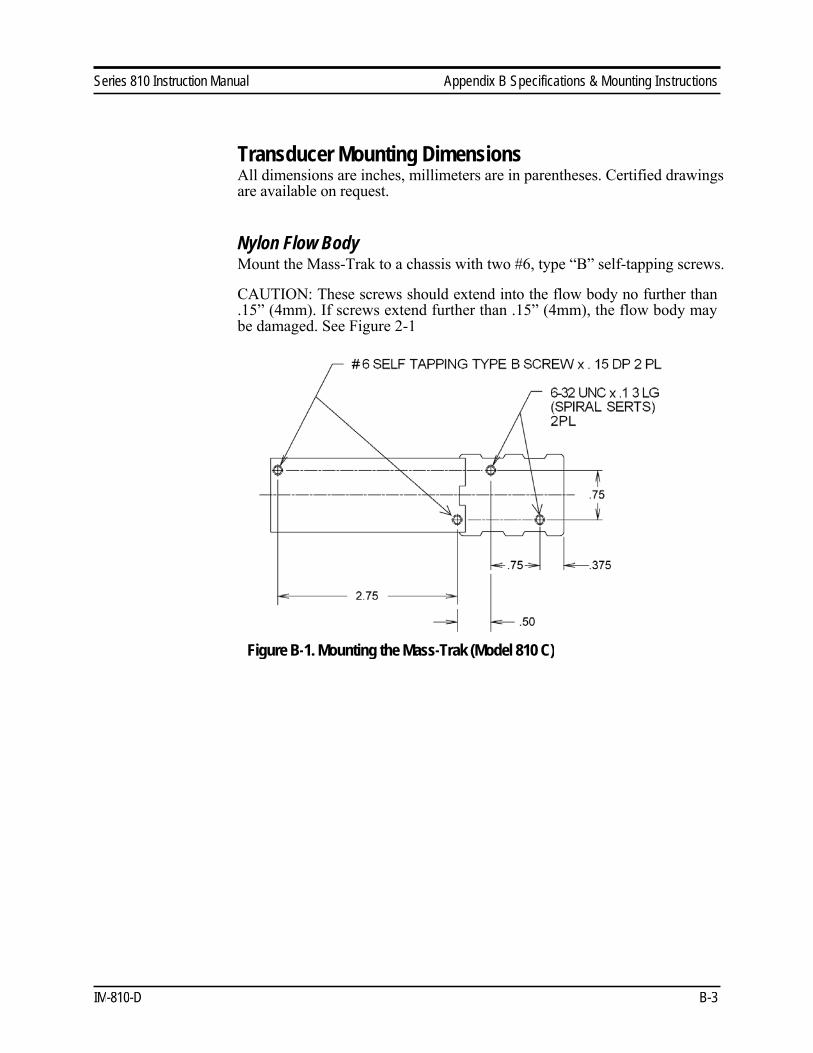
Transducer Mounting Dimensions
All dimensions are inches, millimeters are in parentheses. Certified drawings
are available on request.
Nylon Flow Body
Mount the Mass-Trak to a chassis with two #6, type “B” self-tapping screws.
CAUTION: These screws should extend into the flow body no further than
.15” (4mm). If screws extend further than .15” (4mm), the flow body may
be damaged. See Figure 2-1
Figure B-1. Mounting the Mass-Trak (Model 810 C)
IM-810-D B-3
Appendix B Specifications & Mounting Instructions Series 810 Instruction Manual
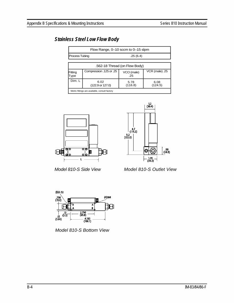
Stainless Steel Low Flow Body
Flow Range, 0–10 sccm to 0–15 slpm
Process Tubing .25 (6.4)
.562-18 Thread (on Flow Body)
Fitting
Type
Compression .125 or .25 VCO (male)
.25
VCR (male) .25
Dim. L 6.02
(122.9 or 127.0)
5.78
(116.8)
6.08
(124.5)
Metric fittings are available, consult factory
Model 810-S Side View Model 810-S Outlet View
Model 810-S Bottom View
B-4 IM-83/84/86-F

Series 810 Instruction Manual Appendix B Specifications & Mounting Instructions
Stainless Steel Medium Flow Body
Flow Range, 0–10 sccm to 0–15 slpm
Process Tubing .25 (6.4)
.562-18 Thread (on Flow Body)
Fitting
Type
Compression .125 or .25 VCO (male)
.25
VCR (male) .25
Dim. L 7.17
(122.9 or 127.0)
6.67
(116.8)
6.97
(124.5)
Metric fittings are available, consult factory
Model 810-S Side View Model 810-S Outlet View
Model 810-S Bottom View
IM-810-D B-5

Series 810 Appendix C Pin Connection
Appendix C Pin Connections
IM-81-D C-1
Series 810 Appendix D Purge and Valve Off Connections
Appendix D Purge and Valve Off Connections
IM-81-D D-1