Embed Size (px)
Citation preview
X-ray Physics
Ho Kyung [email protected]
Pusan National University
Lectures on Digital Radiography
Ch. 1 HMI
References
J. M. Boone, "X-ray Production, Interaction, and Detection in Diagnostic Imaging," in Handbook of Medical Imaging Perception and Techniques, J. Beutel, H. L. Kundel, and R. L. Van Metter, Eds., Bellingham, WA, USA: SPIE, 2000, ch. 1, pp. 1-77.
2
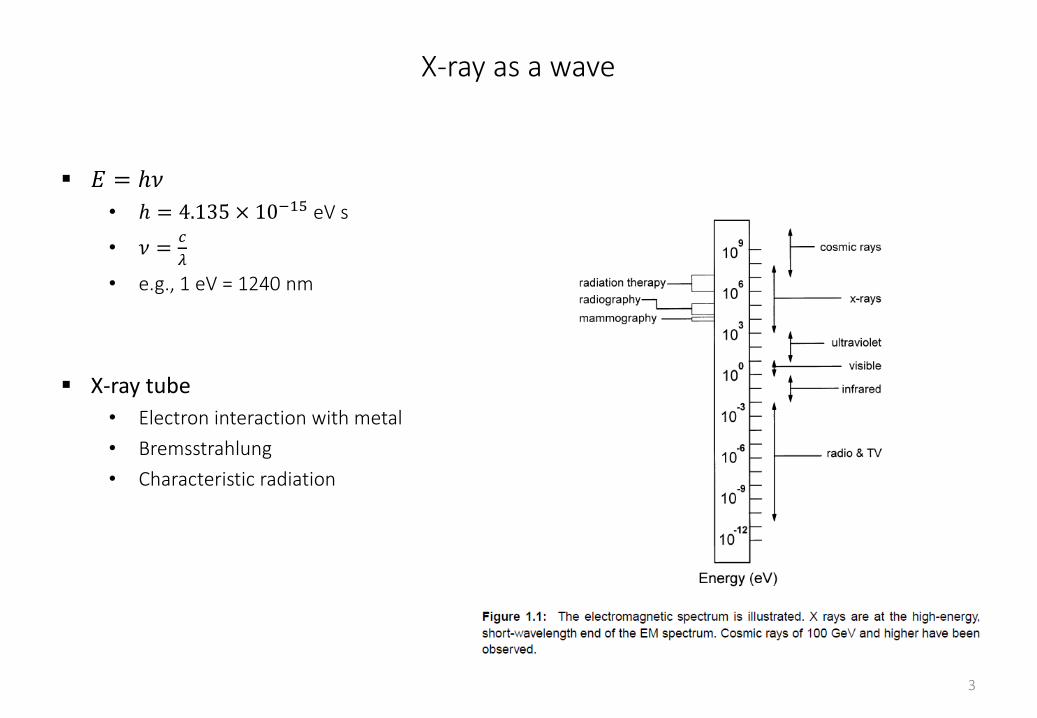
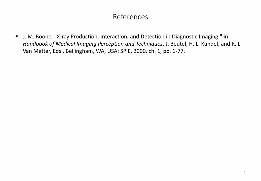
X-ray as a wave
𝐸 = ℎ𝜈
• ℎ = 4.135 × 10⁻¹⁵ eV s
• 𝜈 =𝑐
𝜆
• e.g., 1 eV = 1240 nm
X-ray tube
• Electron interaction with metal
• Bremsstrahlung
• Characteristic radiation
3
Bremsstrahlung
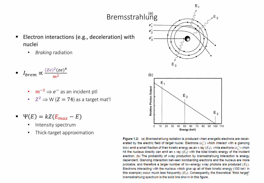
Electron interactions (e.g., deceleration) with nuclei
• Braking radiation
𝐼𝑏𝑟𝑒𝑚 ∝(𝑍𝑒)2(𝑧𝑒)4
𝑚2
• 𝑚−2 𝑒− as an incident ptl
• 𝑍2 W (𝑍 = 74) as a target mat'l
Ψ 𝐸 = 𝑘𝑍(𝐸𝑚𝑎𝑥 − 𝐸)
• Intensity spectrum
• Thick-target approximation
4
Characteristic x-ray
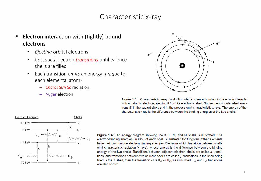
Electron interaction with (tightly) bound electrons
• Ejecting orbital electrons
• Cascaded electron transitions until valence shells are filled
• Each transition emits an energy (unique to each elemental atom)
– Characteristic radiation
– Auger electron
5
6
X-ray tube
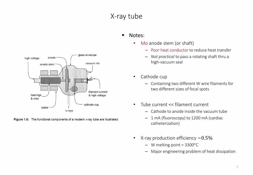
Notes:
• Mo anode stem (or shaft)
– Poor heat conductor to reduce heat transfer
– Not practical to pass a rotating shaft thru a high-vacuum seal
• Cathode cup
– Containing two different W wire filaments for two different sizes of focal spots
• Tube current << filament current
– Cathode to anode inside the vacuum tube
– 1 mA (fluoroscopy) to 1200 mA (cardiac catheterization)
• X-ray production efficiency ~0.5%
– W melting point = 3300C
– Major engineering problem of heat dissipation
7
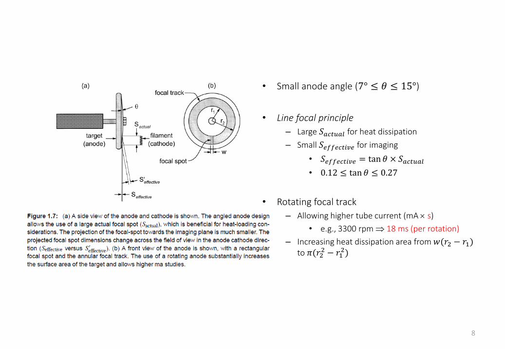
• Small anode angle (7° ≤ 𝜃 ≤ 15°)
• Line focal principle
– Large 𝑆𝑎𝑐𝑡𝑢𝑎𝑙 for heat dissipation
– Small 𝑆𝑒𝑓𝑓𝑒𝑐𝑡𝑖𝑣𝑒 for imaging
• 𝑆𝑒𝑓𝑓𝑒𝑐𝑡𝑖𝑣𝑒 = tan 𝜃 × 𝑆𝑎𝑐𝑡𝑢𝑎𝑙
• 0.12 ≤ tan 𝜃 ≤ 0.27
• Rotating focal track
– Allowing higher tube current (mA s)
• e.g., 3300 rpm 18 ms (per rotation)
– Increasing heat dissipation area from 𝑤(𝑟2 − 𝑟1)to 𝜋(𝑟2
2 − 𝑟12)
8
9
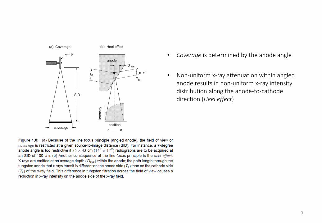
• Coverage is determined by the anode angle
• Non-uniform x-ray attenuation within angled anode results in non-uniform x-ray intensity distribution along the anode-to-cathode direction (Heel effect)
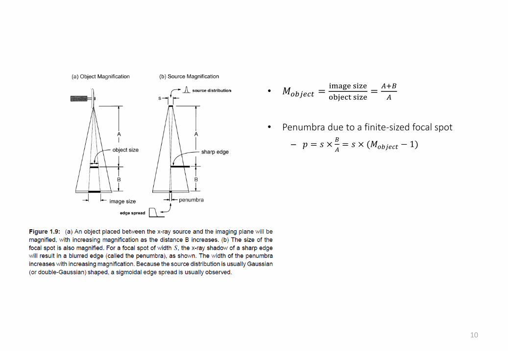
• 𝑀𝑜𝑏𝑗𝑒𝑐𝑡 =image size
object size=
𝐴+𝐵
𝐴
• Penumbra due to a finite-sized focal spot
– 𝑝 = 𝑠 ×𝐵
𝐴= 𝑠 × (𝑀𝑜𝑏𝑗𝑒𝑐𝑡 − 1)
10
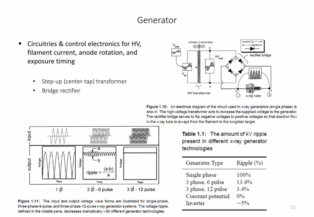
Generator
Circuitries & control electronics for HV, filament current, anode rotation, and exposure timing
• Step-up (center-tap) transformer
• Bridge rectifier
11
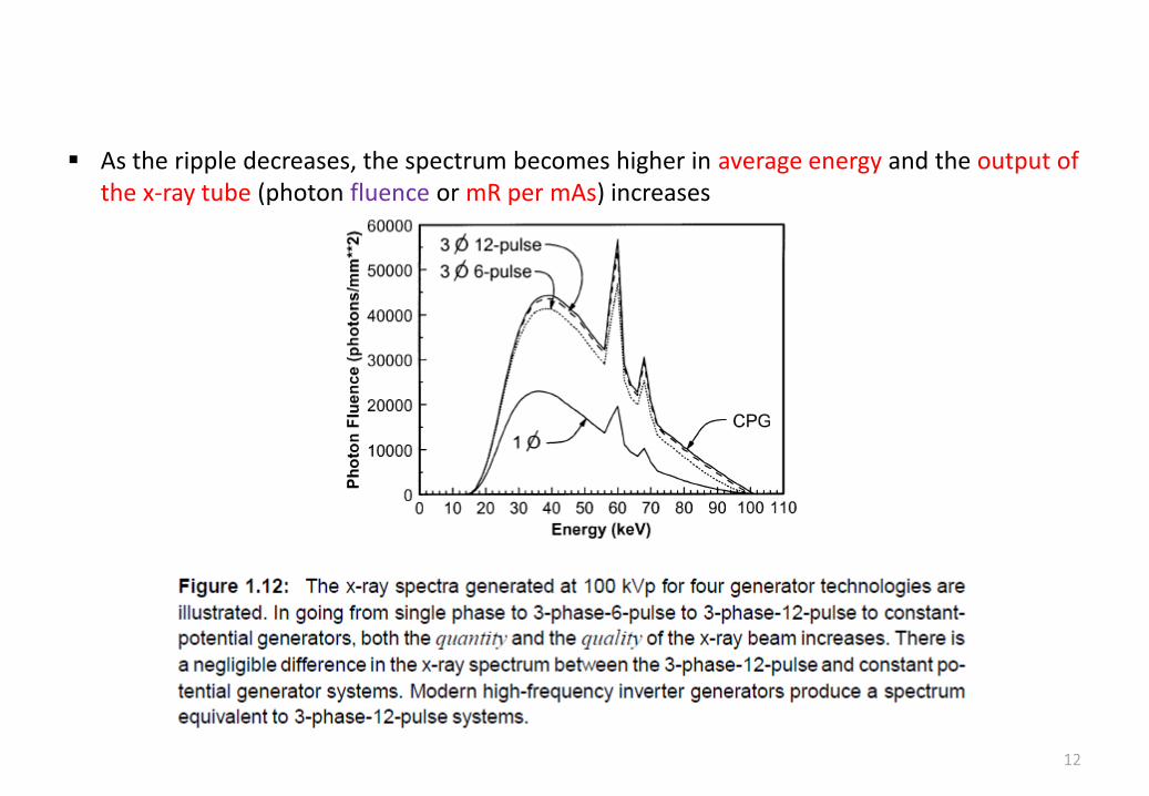
As the ripple decreases, the spectrum becomes higher in average energy and the output of the x-ray tube (photon fluence or mR per mAs) increases
12
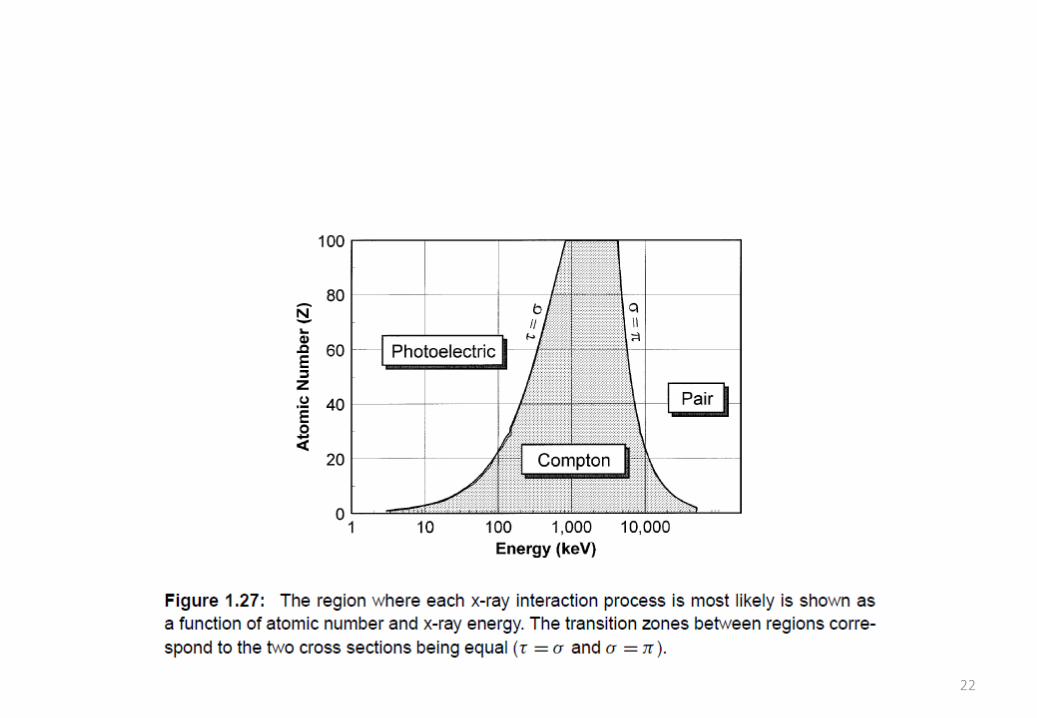
X-ray interactions
Photoelectric effect
Rayleigh scattering
Compton scattering
Pair production
Triplet production
13
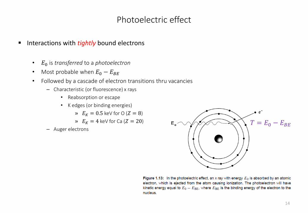
Photoelectric effect
Interactions with tightly bound electrons
• 𝐸0 is transferred to a photoelectron
• Most probable when 𝐸0 − 𝐸𝐵𝐸• Followed by a cascade of electron transitions thru vacancies
– Characteristic (or fluorescence) x rays
• Reabsorption or escape
• K edges (or binding energies)
» 𝐸𝐾 = 0.5 keV for O (𝑍 = 8)
» 𝐸𝐾 = 4 keV for Ca (𝑍 = 20)
– Auger electrons
14
𝑇 = 𝐸0 − 𝐸𝐵𝐸
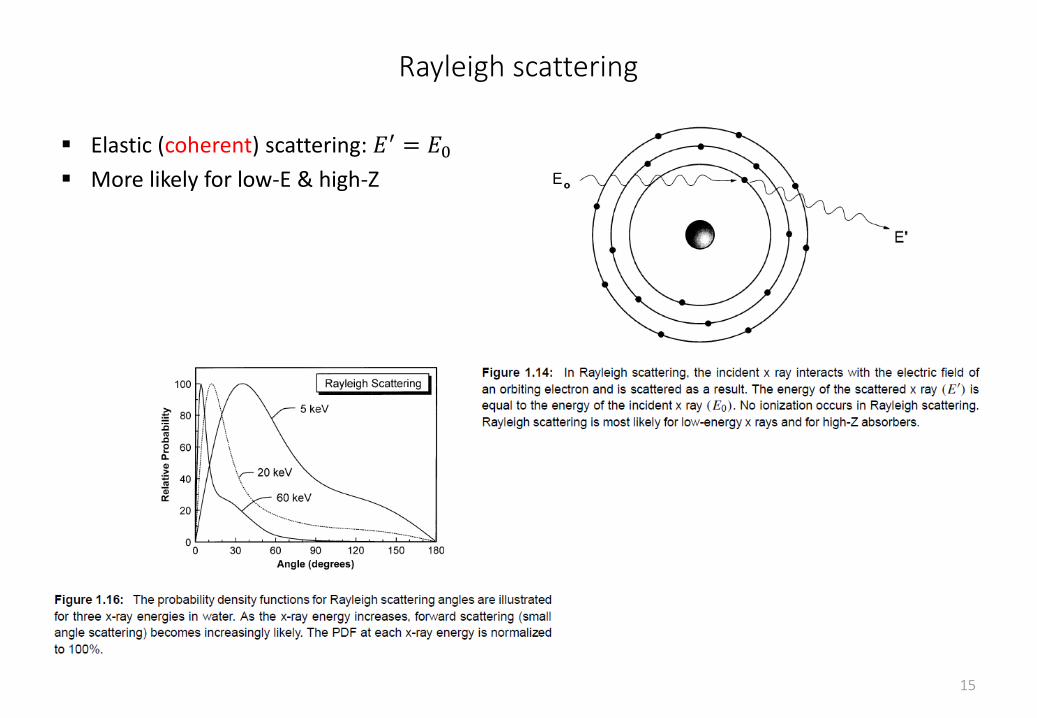
Rayleigh scattering
Elastic (coherent) scattering: 𝐸′ = 𝐸0 More likely for low-E & high-Z
15
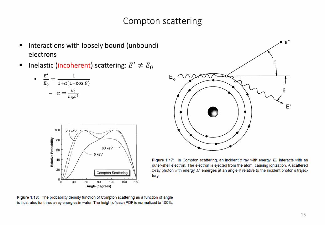
Compton scattering
Interactions with loosely bound (unbound) electrons
Inelastic (incoherent) scattering: 𝐸′ ≠ 𝐸0
•𝐸′
𝐸0=
1
1+𝛼(1−cos 𝜃)
– 𝛼 =𝐸0
𝑚0𝑐2
16
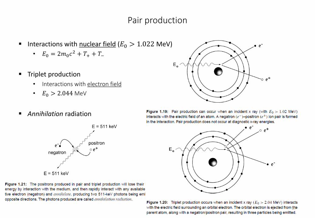
Pair production
Interactions with nuclear field (𝐸0 > 1.022 MeV)
• 𝐸0 = 2𝑚0𝑐2 + 𝑇+ + 𝑇−
Triplet production
• Interactions with electron field
• 𝐸0 > 2.044 MeV
Annihilation radiation
17
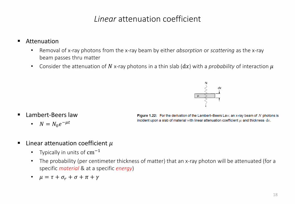
Linear attenuation coefficient
Attenuation
• Removal of x-ray photons from the x-ray beam by either absorption or scattering as the x-ray beam passes thru matter
• Consider the attenuation of 𝑁 x-ray photons in a thin slab (d𝑥) with a probability of interaction 𝜇
Lambert-Beers law
• 𝑁 = 𝑁0𝑒−𝜇𝑡
Linear attenuation coefficient 𝜇
• Typically in units of cm−1
• The probability (per centimeter thickness of matter) that an x-ray photon will be attenuated (for a specific material & at a specific energy)
• 𝜇 = 𝜏 + 𝜎𝑟 + 𝜎 + 𝜋 + 𝛾
18
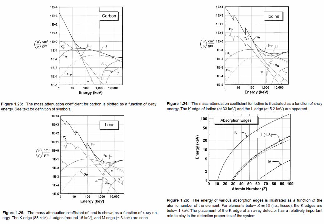
Mass attenuation coefficient
𝜇 depends linearly on the 𝜌 of material (e.g., water: vapor, liquid, ice)
Mass attenuation coefficient 𝜇
𝜌
• To compensate the 𝜌-dependency
• In units of cm2 g−1
• 𝑁 = 𝑁0𝑒−
𝜇
𝜌𝜌𝑡
– 𝜌𝑡 = mass thickness in units of g cm−2
•𝜇
𝜌=
𝜏
𝜌+
𝜎𝑟
𝜌+
𝜎
𝜌+
𝜋
𝜌+
𝛾
𝜌
19
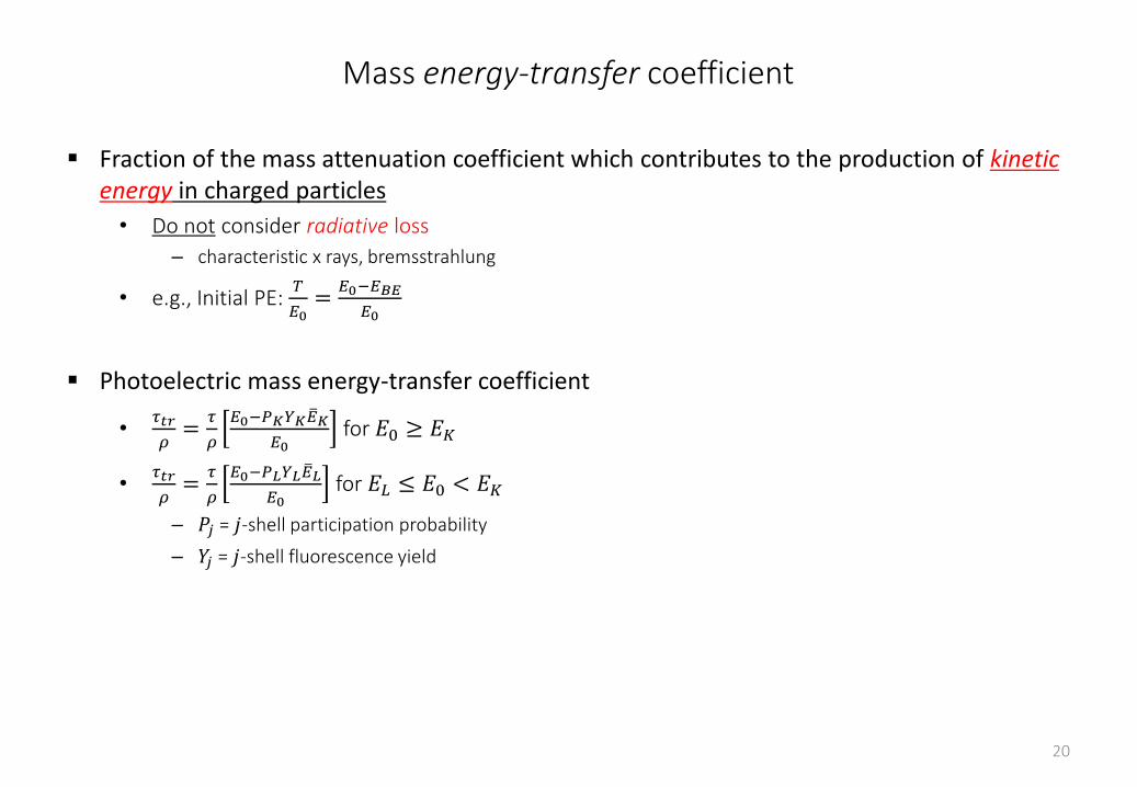
Mass energy-transfer coefficient
Fraction of the mass attenuation coefficient which contributes to the production of kinetic energy in charged particles
• Do not consider radiative loss
– characteristic x rays, bremsstrahlung
• e.g., Initial PE: 𝑇
𝐸0=
𝐸0−𝐸𝐵𝐸
𝐸0
Photoelectric mass energy-transfer coefficient
•𝜏𝑡𝑟
𝜌=
𝜏
𝜌
𝐸0−𝑃𝐾𝑌𝐾 𝐸𝐾
𝐸0for 𝐸0 ≥ 𝐸𝐾
•𝜏𝑡𝑟
𝜌=
𝜏
𝜌
𝐸0−𝑃𝐿𝑌𝐿 𝐸𝐿
𝐸0for 𝐸𝐿 ≤ 𝐸0 < 𝐸𝐾
– 𝑃𝑗 = 𝑗-shell participation probability
– 𝑌𝑗 = 𝑗-shell fluorescence yield
20
21
22
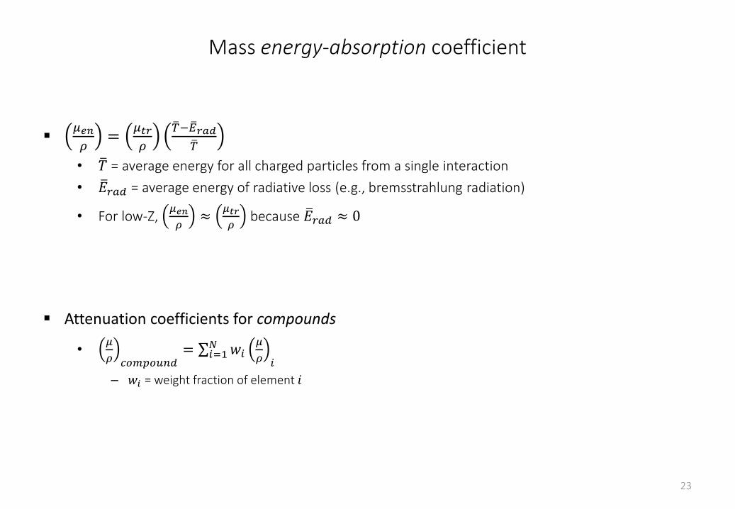
Mass energy-absorption coefficient
𝜇𝑒𝑛
𝜌=
𝜇𝑡𝑟
𝜌
𝑇− 𝐸𝑟𝑎𝑑 𝑇
• 𝑇 = average energy for all charged particles from a single interaction
• 𝐸𝑟𝑎𝑑 = average energy of radiative loss (e.g., bremsstrahlung radiation)
• For low-Z, 𝜇𝑒𝑛
𝜌≈
𝜇𝑡𝑟
𝜌because 𝐸𝑟𝑎𝑑 ≈ 0
Attenuation coefficients for compounds
•𝜇
𝜌 𝑐𝑜𝑚𝑝𝑜𝑢𝑛𝑑= 𝑖=1
𝑁 𝑤𝑖𝜇
𝜌 𝑖
– 𝑤𝑖 = weight fraction of element 𝑖
23
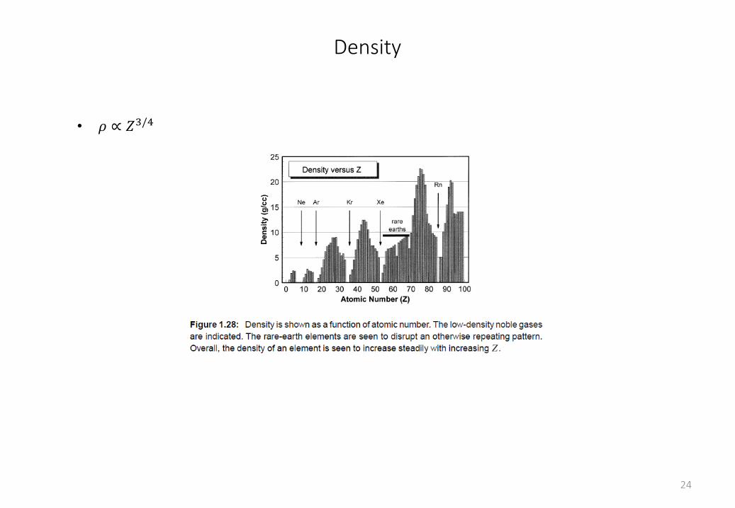
Density
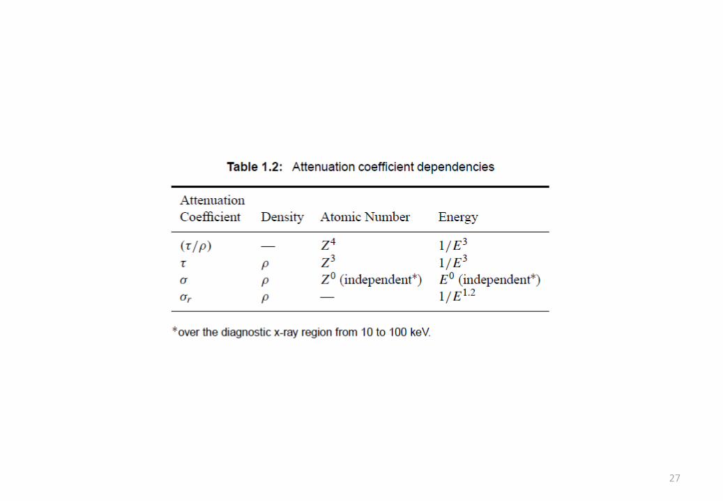
• 𝜌 ∝ 𝑍3/4
24
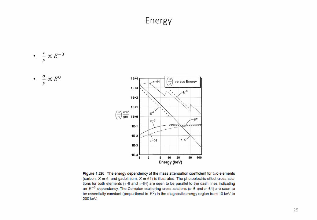
Energy
•𝜏
𝜌∝ 𝐸−3
•𝜎
𝜌∝ 𝐸0
25
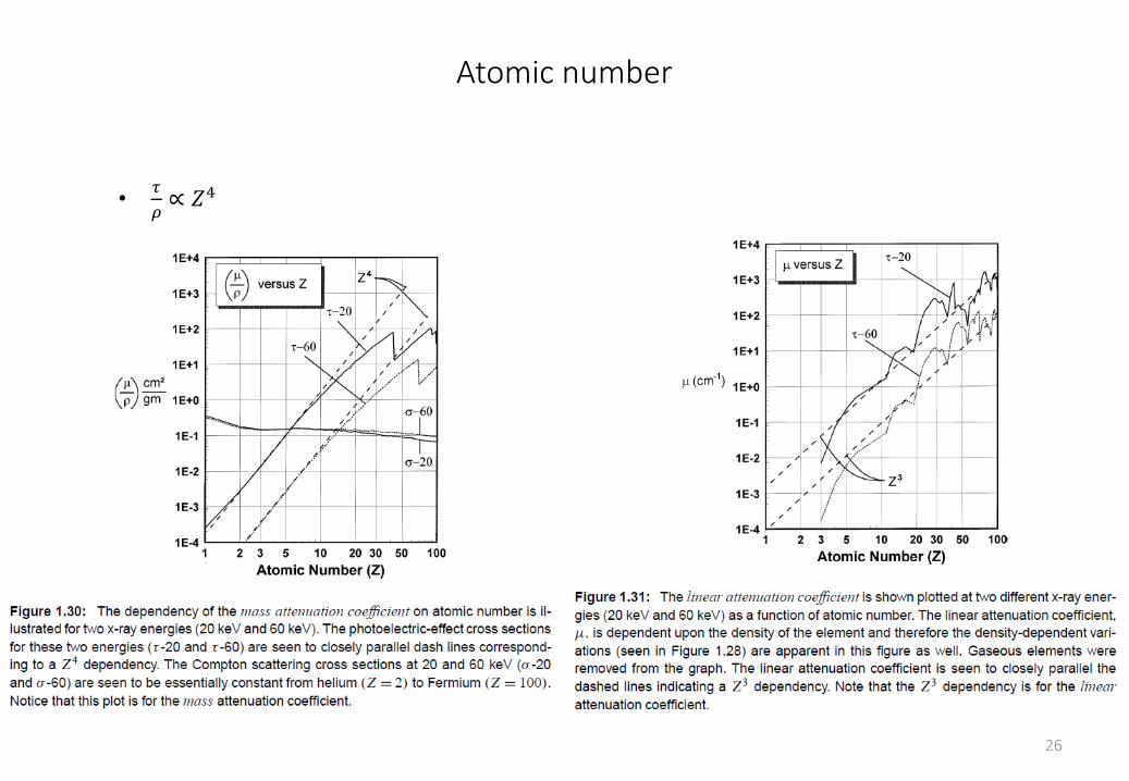
Atomic number
•𝜏
𝜌∝ 𝑍4
•𝜎
𝜌∝ 𝑍0
26
27
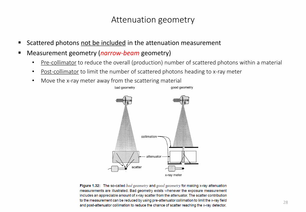
Attenuation geometry
Scattered photons not be included in the attenuation measurement
Measurement geometry (narrow-beam geometry)
• Pre-collimator to reduce the overall (production) number of scattered photons within a material
• Post-collimator to limit the number of scattered photons heading to x-ray meter
• Move the x-ray meter away from the scattering material
28
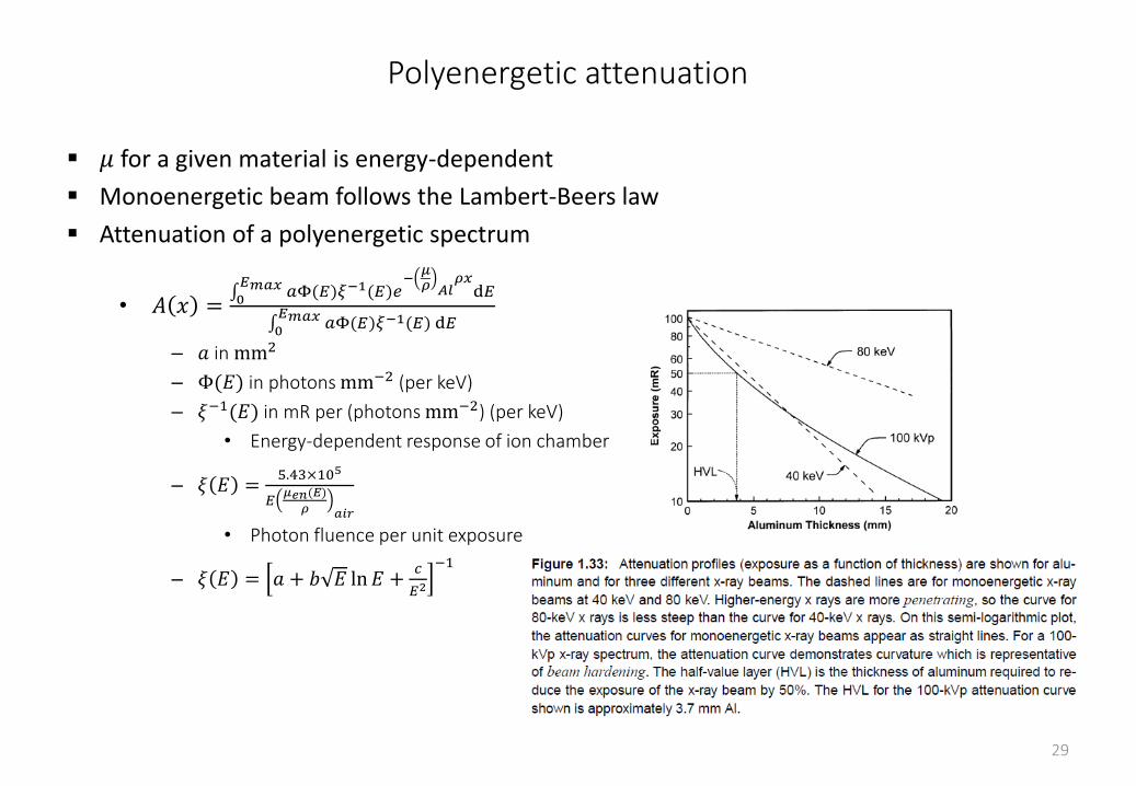
Polyenergetic attenuation
𝜇 for a given material is energy-dependent
Monoenergetic beam follows the Lambert-Beers law
Attenuation of a polyenergetic spectrum
• 𝐴 𝑥 = 0𝐸𝑚𝑎𝑥 𝑎Φ(𝐸)𝜉−1(𝐸)𝑒
−𝜇𝜌 𝐴𝑙
𝜌𝑥d𝐸
0𝐸𝑚𝑎𝑥 𝑎Φ(𝐸)𝜉−1(𝐸) d𝐸
– 𝑎 in mm2
– Φ(𝐸) in photons mm−2 (per keV)
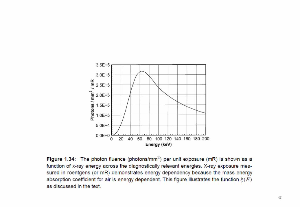
– 𝜉−1(𝐸) in mR per (photons mm−2) (per keV)
• Energy-dependent response of ion chamber
– 𝜉 𝐸 =5.43×10⁵
𝐸𝜇𝑒𝑛(𝐸)
𝜌 𝑎𝑖𝑟
• Photon fluence per unit exposure
– 𝜉 𝐸 = 𝑎 + 𝑏 𝐸 ln𝐸 +𝑐
𝐸2
−1
29
30
Half-value layer
A well-know parameter used to characterize beam quality (i.e., spectral distribution) in field measurements of attenuation
• Al thickness required to reduce the exposure of the x-ray beam by a factor of 2
• HVL =ln 2
𝜇
• HVL increases with increasing kVp
31
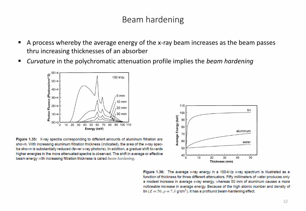
Beam hardening
A process whereby the average energy of the x-ray beam increases as the beam passes thru increasing thicknesses of an absorber
Curvature in the polychromatic attenuation profile implies the beam hardening
32
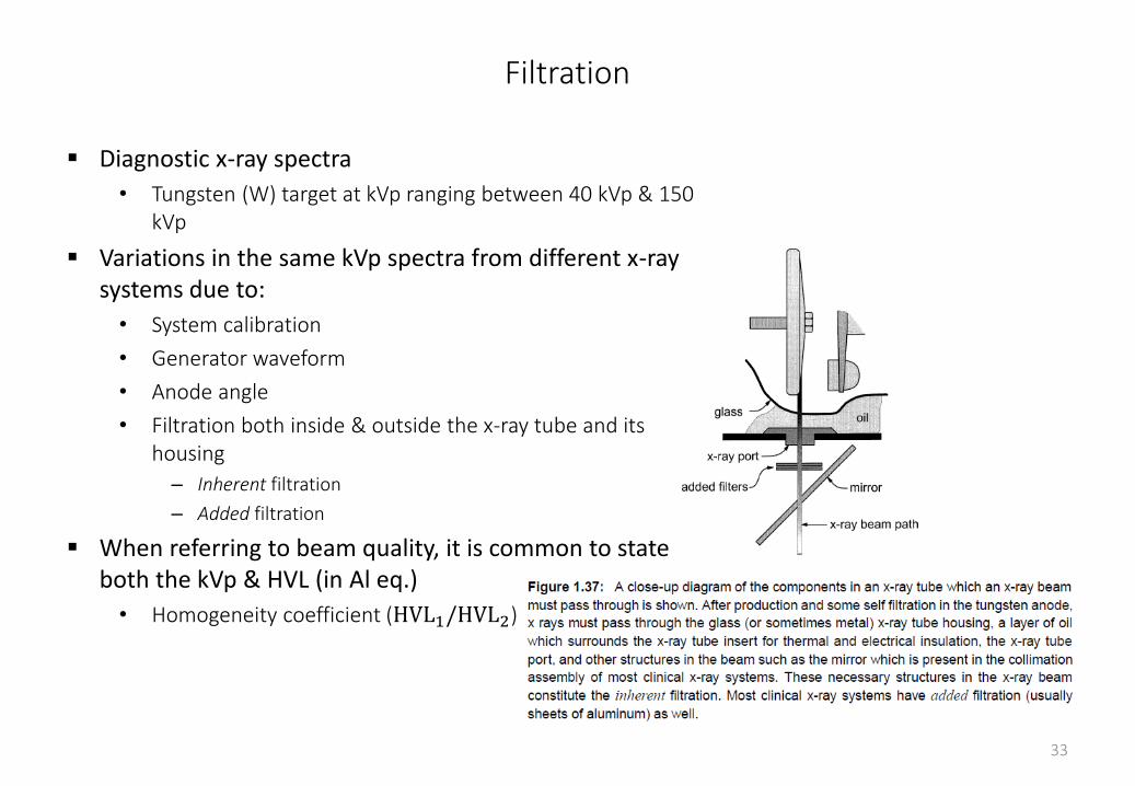
Filtration
Diagnostic x-ray spectra
• Tungsten (W) target at kVp ranging between 40 kVp & 150 kVp
Variations in the same kVp spectra from different x-ray systems due to:
• System calibration
• Generator waveform
• Anode angle
• Filtration both inside & outside the x-ray tube and its housing
– Inherent filtration
– Added filtration
When referring to beam quality, it is common to state both the kVp & HVL (in Al eq.)
• Homogeneity coefficient (HVL1/HVL2)
33
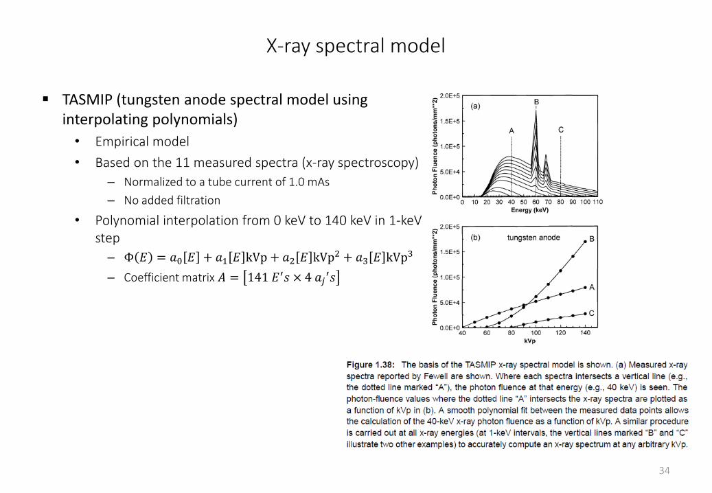
X-ray spectral model
TASMIP (tungsten anode spectral model using interpolating polynomials)
• Empirical model
• Based on the 11 measured spectra (x-ray spectroscopy)
– Normalized to a tube current of 1.0 mAs
– No added filtration
• Polynomial interpolation from 0 keV to 140 keV in 1-keV step
– Φ 𝐸 = 𝑎0 𝐸 + 𝑎1 𝐸 kVp + 𝑎2 𝐸 kVp2 + 𝑎3 𝐸 kVp3
– Coefficient matrix 𝐴 = 141 𝐸′𝑠 × 4 𝑎𝑗′𝑠
34
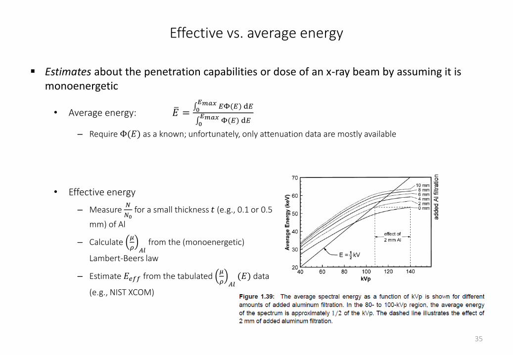
Effective vs. average energy
Estimates about the penetration capabilities or dose of an x-ray beam by assuming it is monoenergetic
• Average energy: 𝐸 = 0𝐸𝑚𝑎𝑥 𝐸Φ(𝐸) d𝐸
0𝐸𝑚𝑎𝑥 Φ(𝐸) d𝐸
– Require Φ(𝐸) as a known; unfortunately, only attenuation data are mostly available
35
• Effective energy
– Measure 𝑁
𝑁0for a small thickness 𝑡 (e.g., 0.1 or 0.5
mm) of Al
– Calculate 𝜇
𝜌 𝐴𝑙from the (monoenergetic)
Lambert-Beers law
– Estimate 𝐸𝑒𝑓𝑓 from the tabulated 𝜇
𝜌 𝐴𝑙(𝐸) data
(e.g., NIST XCOM)
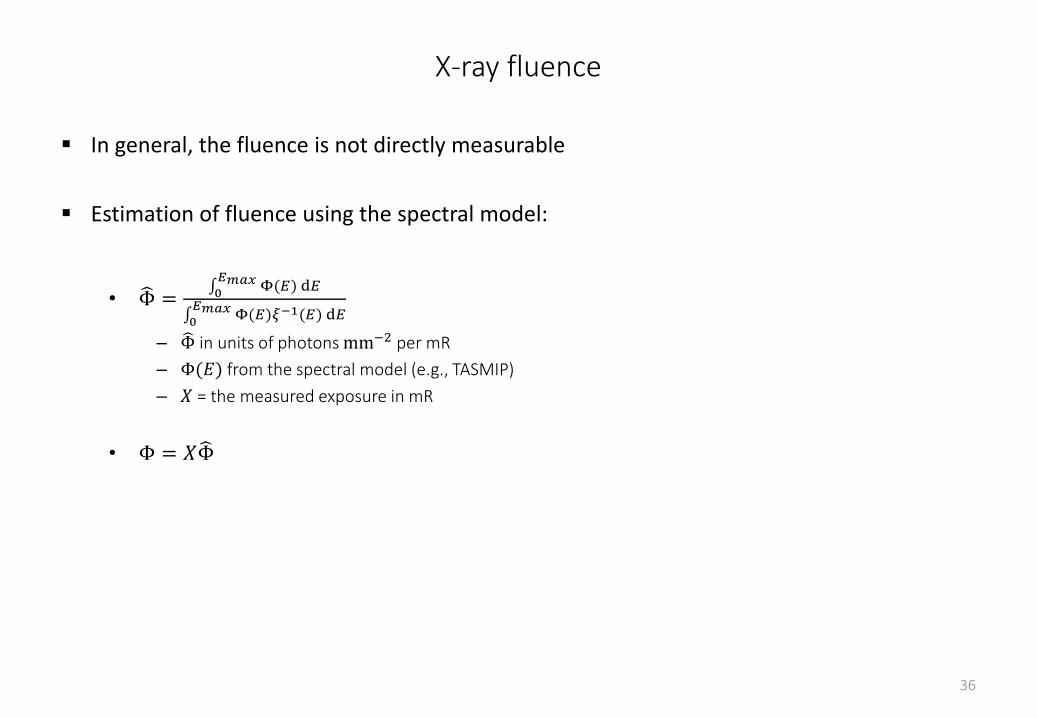
X-ray fluence
In general, the fluence is not directly measurable
Estimation of fluence using the spectral model:
• Φ = 0𝐸𝑚𝑎𝑥 Φ(𝐸) d𝐸
0𝐸𝑚𝑎𝑥 Φ(𝐸)𝜉−1(𝐸) d𝐸
– Φ in units of photons mm−2 per mR
– Φ(𝐸) from the spectral model (e.g., TASMIP)
– 𝑋 = the measured exposure in mR
• Φ = 𝑋 Φ
36
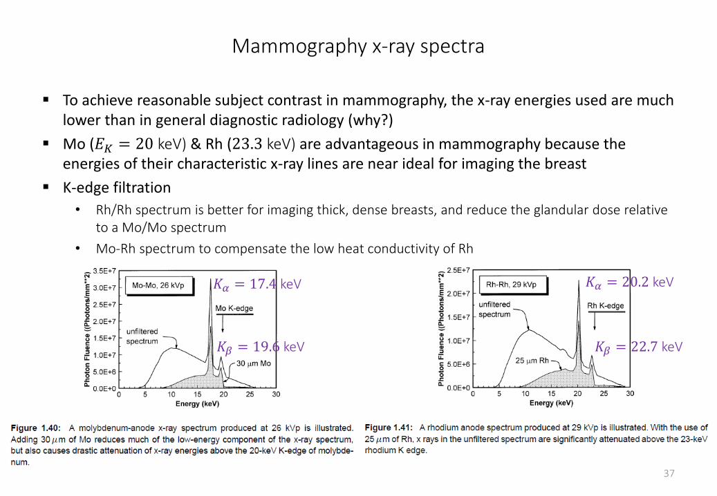
Mammography x-ray spectra
To achieve reasonable subject contrast in mammography, the x-ray energies used are much lower than in general diagnostic radiology (why?)
Mo (𝐸𝐾 = 20 keV) & Rh (23.3 keV) are advantageous in mammography because the energies of their characteristic x-ray lines are near ideal for imaging the breast
K-edge filtration
• Rh/Rh spectrum is better for imaging thick, dense breasts, and reduce the glandular dose relative to a Mo/Mo spectrum
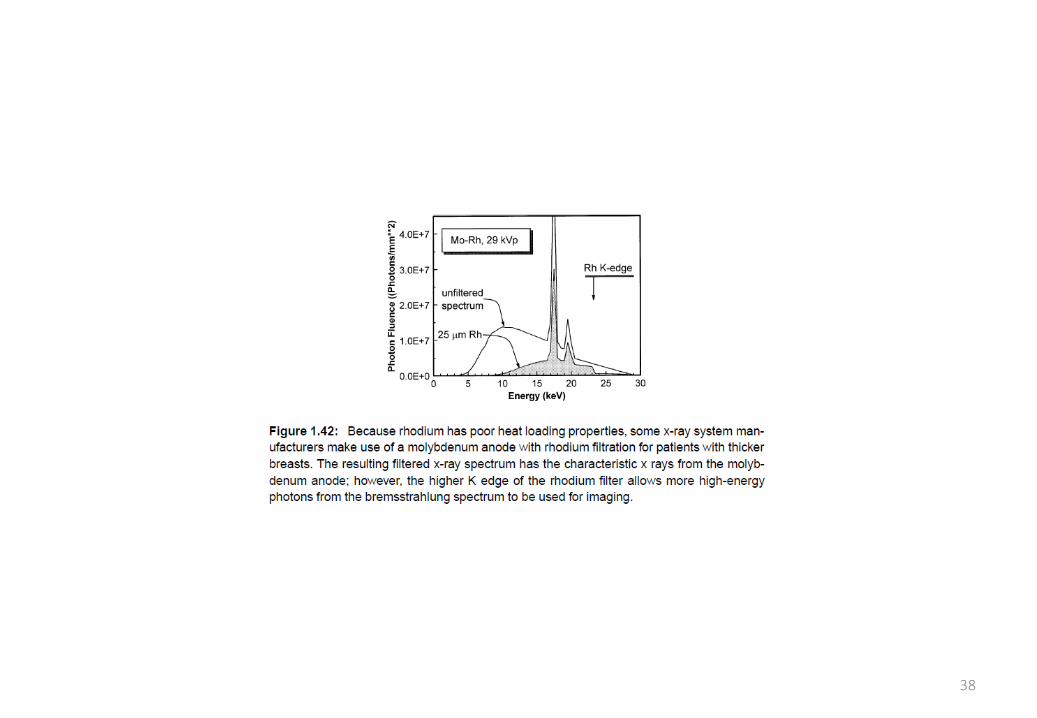
• Mo-Rh spectrum to compensate the low heat conductivity of Rh
37
𝐾𝛼 = 17.4 keV
𝐾𝛽 = 19.6 keV
𝐾𝛼 = 20.2 keV
𝐾𝛽 = 22.7 keV
38
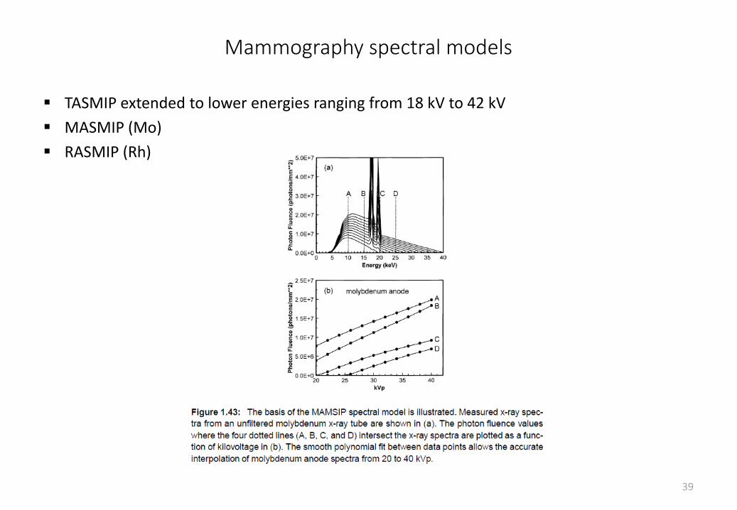
Mammography spectral models
TASMIP extended to lower energies ranging from 18 kV to 42 kV
MASMIP (Mo)
RASMIP (Rh)
39
Dosimetry
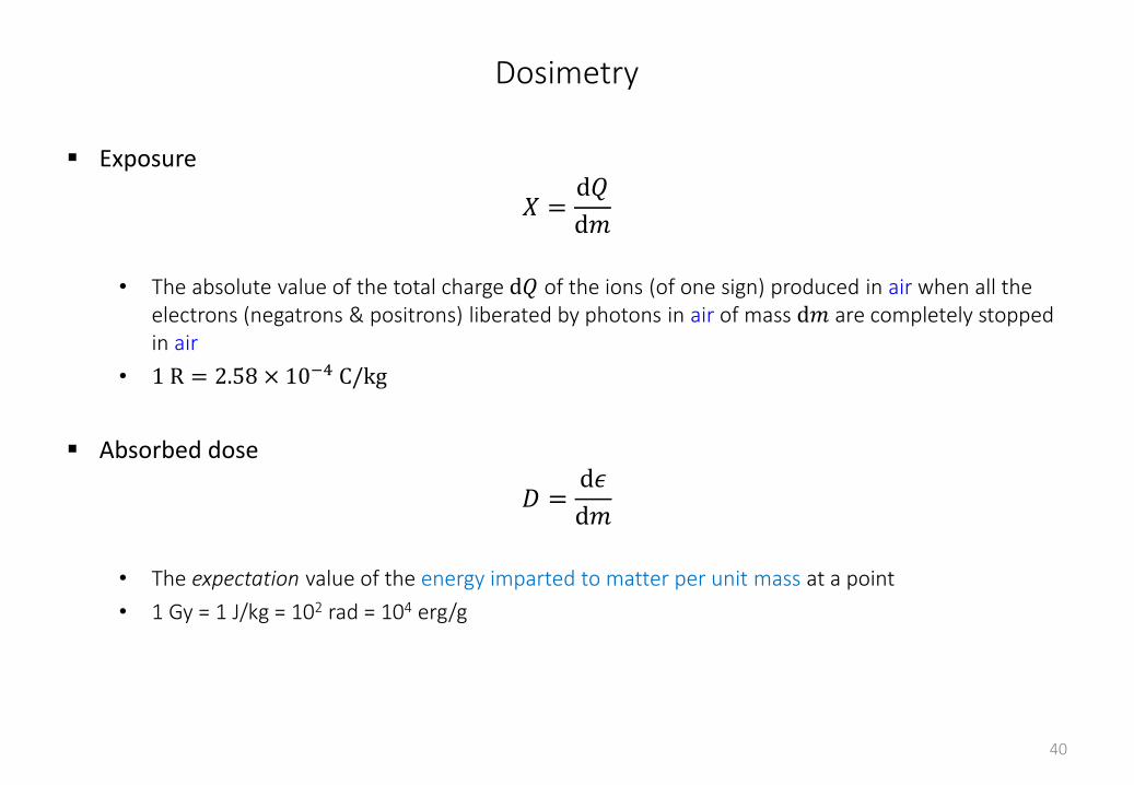
Exposure
𝑋 =d𝑄
d𝑚
• The absolute value of the total charge d𝑄 of the ions (of one sign) produced in air when all the electrons (negatrons & positrons) liberated by photons in air of mass d𝑚 are completely stopped in air
• 1 R = 2.58 × 10⁻⁴ C/kg
Absorbed dose
𝐷 =d𝜖
d𝑚
• The expectation value of the energy imparted to matter per unit mass at a point
• 1 Gy = 1 J/kg = 102 rad = 104 erg/g
40
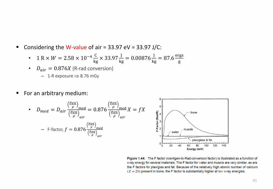
Considering the W-value of air = 33.97 eV = 33.97 J/C:
• 1 R ×𝑊 = 2.58 × 10⁻⁴C
kg× 33.97
J
kg= 0.00876
J
kg= 87.6
ergs
g
• 𝐷𝑎𝑖𝑟 = 0.876𝑋 (R-rad conversion)
– 1-R exposure 8.76 mGy
For an arbitrary medium:
• 𝐷𝑚𝑒𝑑 = 𝐷𝑎𝑖𝑟
𝜇𝑒𝑛𝜌 𝑚𝑒𝑑𝜇𝑒𝑛𝜌 𝑎𝑖𝑟
= 0.876
𝜇𝑒𝑛𝜌 𝑚𝑒𝑑𝜇𝑒𝑛𝜌 𝑎𝑖𝑟
𝑋 = 𝑓𝑋
– F-factor, 𝑓 = 0.876
𝜇𝑒𝑛𝜌 𝑚𝑒𝑑𝜇𝑒𝑛𝜌 𝑎𝑖𝑟
41
Kerma
Kinetic energy released in media
𝐾 ≡d𝜖𝑡𝑟d𝑚
• The expectation value of the energy transferred to charged particles per unit mass at a point of interest, including radiative-loss energy but excluding energy passed from one charged particle to another
• 𝐾 = 𝑘 0𝐸𝑚𝑎𝑥Φ 𝐸
𝜇𝑡𝑟(𝐸)
𝜌 𝑚𝑒𝑑𝐸 d𝐸
• For air, 𝐾𝑎𝑖𝑟 = 𝐷𝑎𝑖𝑟 because 𝜇𝑡𝑟
𝜌≈
𝜇
𝜌(negligible fluorescence)
42
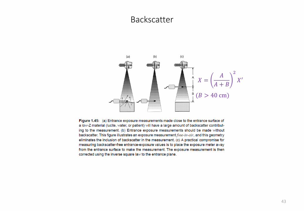
Backscatter
43
𝑋 =𝐴
𝐴 + 𝐵
2
𝑋′
(𝐵 > 40 cm)
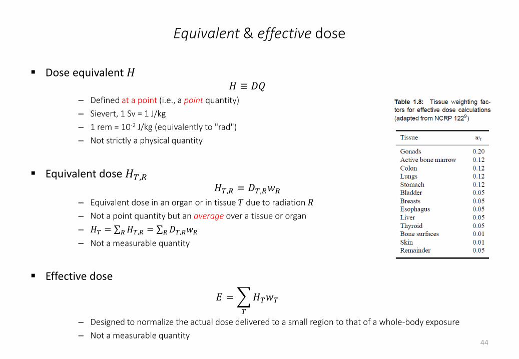
Equivalent & effective dose
Dose equivalent 𝐻𝐻 ≡ 𝐷𝑄
– Defined at a point (i.e., a point quantity)
– Sievert, 1 Sv = 1 J/kg
– 1 rem = 10-2 J/kg (equivalently to "rad")
– Not strictly a physical quantity
Equivalent dose 𝐻𝑇,𝑅
𝐻𝑇,𝑅 = 𝐷𝑇,𝑅𝑤𝑅
– Equivalent dose in an organ or in tissue 𝑇 due to radiation 𝑅
– Not a point quantity but an average over a tissue or organ
– 𝐻𝑇 = 𝑅𝐻𝑇,𝑅 = 𝑅𝐷𝑇,𝑅𝑤𝑅
– Not a measurable quantity
Effective dose
𝐸 =
𝑇
𝐻𝑇𝑤𝑇
– Designed to normalize the actual dose delivered to a small region to that of a whole-body exposure
– Not a measurable quantity44
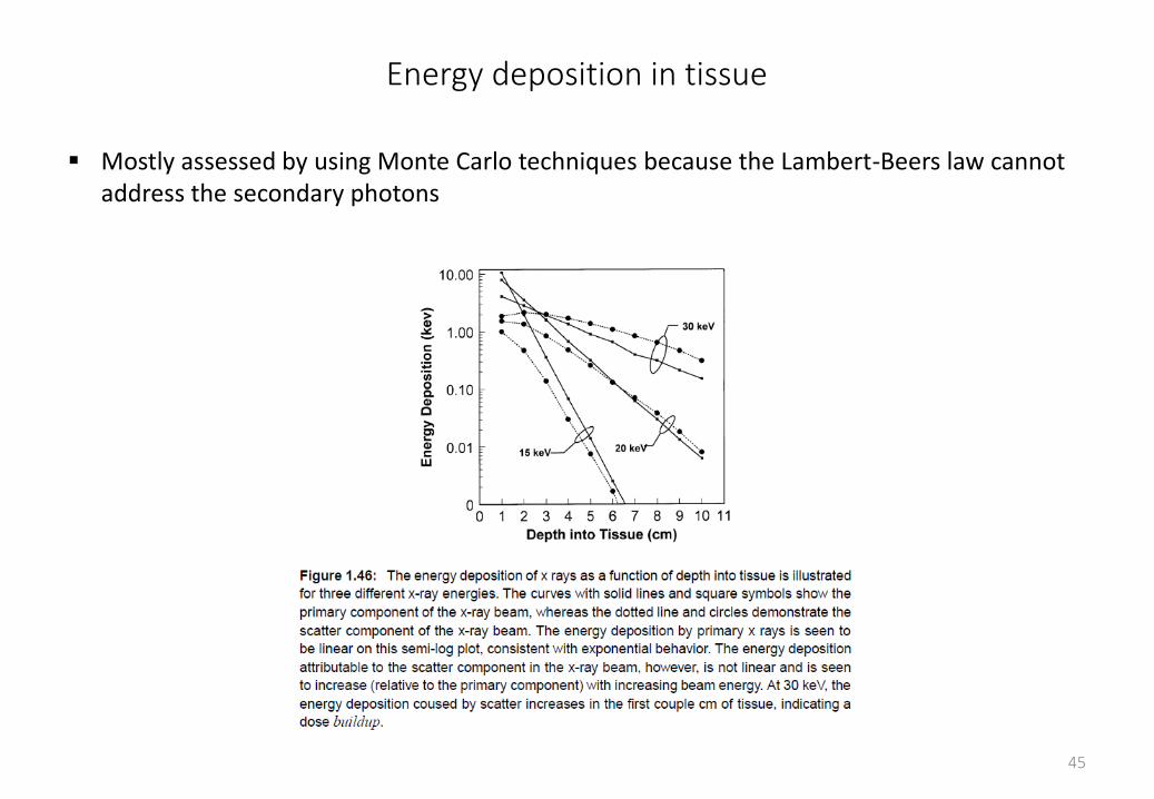
Energy deposition in tissue
Mostly assessed by using Monte Carlo techniques because the Lambert-Beers law cannot address the secondary photons
45
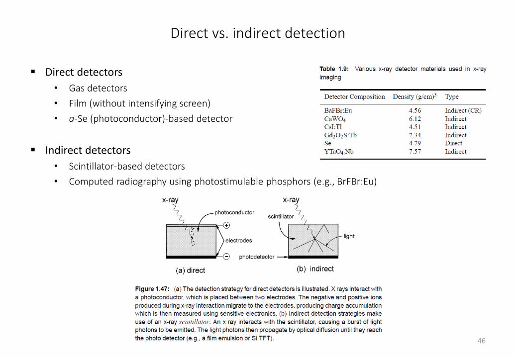
Direct vs. indirect detection
Direct detectors
• Gas detectors
• Film (without intensifying screen)
• a-Se (photoconductor)-based detector
Indirect detectors
• Scintillator-based detectors
• Computed radiography using photostimulable phosphors (e.g., BrFBr:Eu)
46
Activators
Host-luminescent phosphors do not require activators (e.g., CdWO4)
Activators determines:
• Color of the luminescent emission
– Gd2O2S:Tb peak at 545 nm
– Gd2O2S:Eu peak at 626 nm
– Gd2O2S:Pr peak at 506 nm
• Scintillation efficiency (# light photons per absorbed energy)
• Decay time
• Note that the activators has negligible impact on the absorption efficiency of phosphors
47
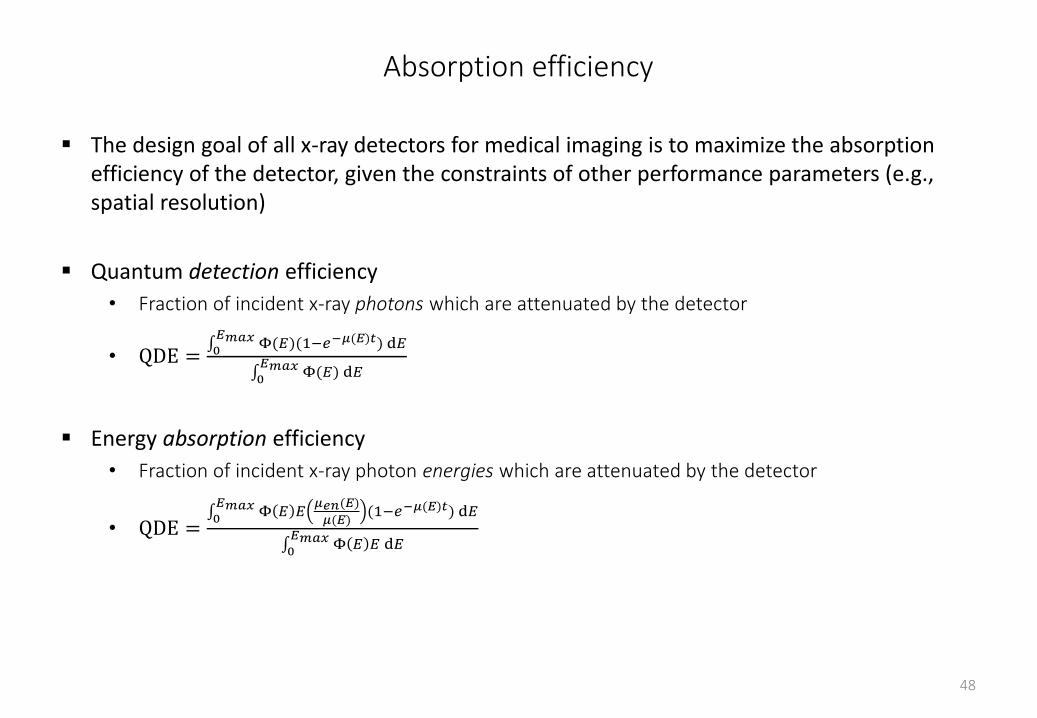
Absorption efficiency
The design goal of all x-ray detectors for medical imaging is to maximize the absorption efficiency of the detector, given the constraints of other performance parameters (e.g., spatial resolution)
Quantum detection efficiency
• Fraction of incident x-ray photons which are attenuated by the detector
• QDE = 0𝐸𝑚𝑎𝑥 Φ(𝐸)(1−𝑒−𝜇(𝐸)𝑡) d𝐸
0𝐸𝑚𝑎𝑥 Φ(𝐸) d𝐸
Energy absorption efficiency
• Fraction of incident x-ray photon energies which are attenuated by the detector
• QDE = 0𝐸𝑚𝑎𝑥 Φ 𝐸 𝐸
𝜇𝑒𝑛(𝐸)
𝜇(𝐸)(1−𝑒−𝜇(𝐸)𝑡) d𝐸
0𝐸𝑚𝑎𝑥 Φ 𝐸 𝐸 d𝐸
48
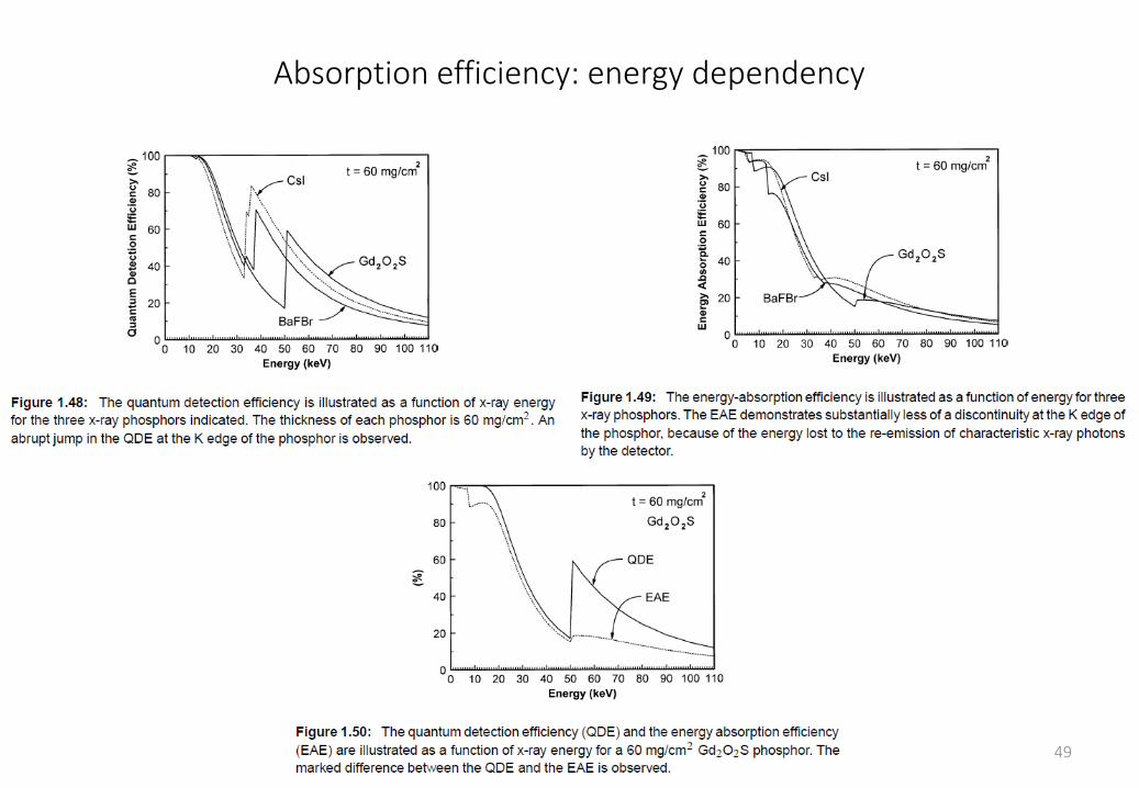
Absorption efficiency: energy dependency
49
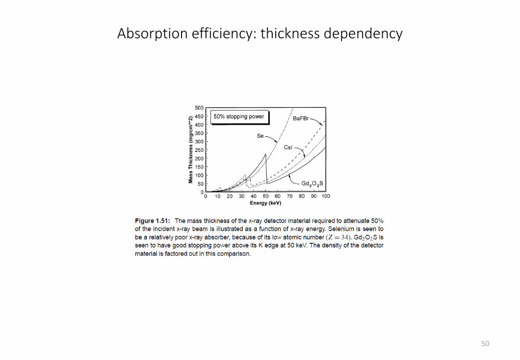
Absorption efficiency: thickness dependency
50
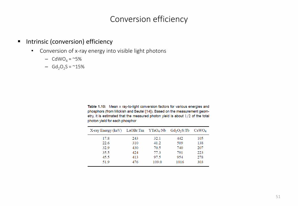
Conversion efficiency
Intrinsic (conversion) efficiency
• Conversion of x-ray energy into visible light photons
– CdWO4 = ~5%
– Gd2O2S = ~15%
51
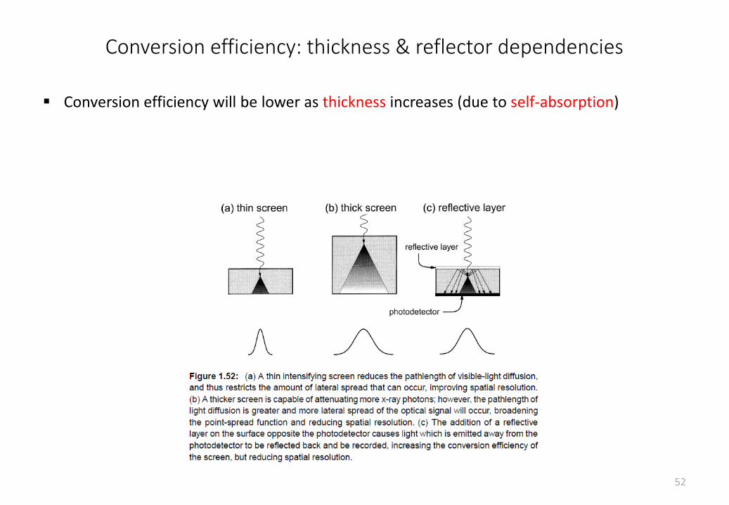
Conversion efficiency: thickness & reflector dependencies
Conversion efficiency will be lower as thickness increases (due to self-absorption)
52
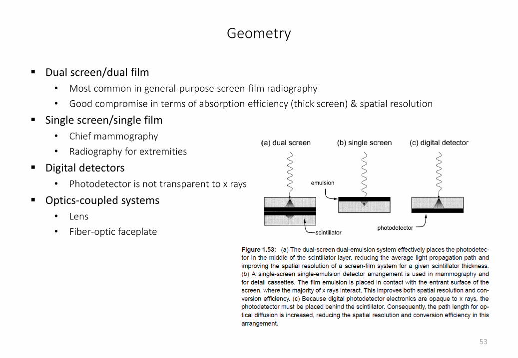
Geometry
Dual screen/dual film
• Most common in general-purpose screen-film radiography
• Good compromise in terms of absorption efficiency (thick screen) & spatial resolution
Single screen/single film
• Chief mammography
• Radiography for extremities
Digital detectors
• Photodetector is not transparent to x rays
Optics-coupled systems
• Lens
• Fiber-optic faceplate
53
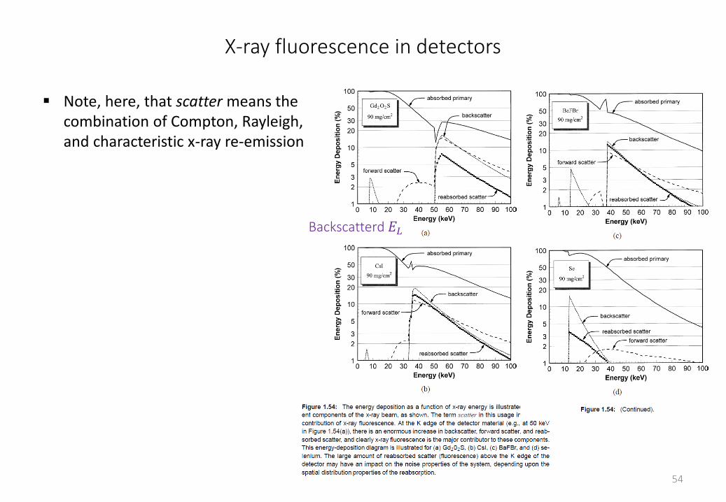
X-ray fluorescence in detectors
54
Backscatterd 𝐸𝐿
Note, here, that scatter means the combination of Compton, Rayleigh, and characteristic x-ray re-emission